WO2024023942A1 - 車両冷却系構造 - Google Patents
車両冷却系構造 Download PDFInfo
- Publication number
- WO2024023942A1 WO2024023942A1 PCT/JP2022/028829 JP2022028829W WO2024023942A1 WO 2024023942 A1 WO2024023942 A1 WO 2024023942A1 JP 2022028829 W JP2022028829 W JP 2022028829W WO 2024023942 A1 WO2024023942 A1 WO 2024023942A1
- Authority
- WO
- WIPO (PCT)
- Prior art keywords
- radiator
- cooling system
- vehicle
- refrigerant
- refrigerant pipe
- Prior art date
- Legal status (The legal status is an assumption and is not a legal conclusion. Google has not performed a legal analysis and makes no representation as to the accuracy of the status listed.)
- Ceased
Links
Images

Classifications
-
- B—PERFORMING OPERATIONS; TRANSPORTING
- B60—VEHICLES IN GENERAL
- B60K—ARRANGEMENT OR MOUNTING OF PROPULSION UNITS OR OF TRANSMISSIONS IN VEHICLES; ARRANGEMENT OR MOUNTING OF PLURAL DIVERSE PRIME-MOVERS IN VEHICLES; AUXILIARY DRIVES FOR VEHICLES; INSTRUMENTATION OR DASHBOARDS FOR VEHICLES; ARRANGEMENTS IN CONNECTION WITH COOLING, AIR INTAKE, GAS EXHAUST OR FUEL SUPPLY OF PROPULSION UNITS IN VEHICLES
- B60K11/00—Arrangement in connection with cooling of propulsion units
- B60K11/02—Arrangement in connection with cooling of propulsion units with liquid cooling
- B60K11/04—Arrangement or mounting of radiators, radiator shutters, or radiator blinds
Definitions
- the present invention relates to a vehicle cooling system structure in an electric vehicle that includes a drive device including an electric motor as a traveling drive source, a battery, and a cooling system that cools these.
- JP2021-000860A discloses a vehicle cooling system structure for an electric vehicle that is equipped with electric equipment including a battery under the cabin and a drive motor on the rear axle, and a cooling system that cools these.
- a battery cooling radiator and a high-power cooling radiator are arranged at the front of the vehicle, and the cooling water pipes led from the left and right sides of these radiators are placed close together in the area under the front hood, and then placed in the center of the vehicle. Connect to the battery and drive motor via the vicinity.
- Some electric vehicles have a layout in which an internal combustion engine for power generation is mounted in the space below the front hood (inside the engine room). If the vehicle cooling system structure of JP2021-000860A is applied to such an electric vehicle, the cooling water pipe will be placed close to the high-temperature internal combustion engine. Therefore, the amount of heat transferred from the internal combustion engine to the cooling water pipe increases. In particular, the cooling water flowing through the cooling water piping connected to the battery is required to be maintained at a lower temperature than the cooling water used for cooling electrical equipment (powerful electrical equipment) including a drive motor. Therefore, if the amount of heat transferred from the internal combustion engine to the cooling water pipe connected to the battery increases, there is a possibility that the desired cooling function will not be achieved.
- an object of the present invention is to provide a vehicle cooling system structure that can suppress heat transfer from an internal combustion engine to a cooling water pipe connected to a battery.
- an internal combustion engine a drive device including an electric motor as a traveling drive source, a battery that charges electric power generated by driving the internal combustion engine, and a first refrigerant connected to the drive device.
- a vehicle cooling system structure for an electric vehicle which includes a pipe, a second refrigerant pipe connected to a battery, and a radiator disposed in front of the vehicle and radiating heat to the refrigerant flowing through the first refrigerant pipe and the second refrigerant pipe. be done.
- the internal combustion engine and the drive device are arranged in parallel in one side area and the other side area, respectively, which are separated in the vehicle width direction of the electric vehicle.
- the second refrigerant pipe extends from the radiator through the region outside the drive device in the other region and is connected to the battery.
- the drive device outer region is a region located outside the drive device in the vehicle width direction and on the opposite side to the internal combustion engine.
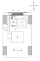
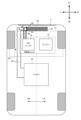
- FIG. 1 is a plan view of main parts of a vehicle cooling system structure according to a first embodiment.
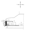
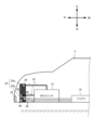
- FIG. 2 is a side view of main parts of the vehicle cooling system structure according to the first embodiment.
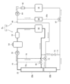
- FIG. 3 is a block diagram illustrating the configuration of a cooling system installed in an electric vehicle.
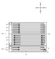
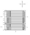
- FIG. 4 is a diagram showing the structure of the radiator according to the first embodiment.
- FIG. 5 is a plan view of the main parts of the vehicle cooling system structure according to the second embodiment.
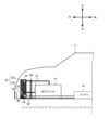
- FIG. 6 is a side view of the main parts of the vehicle cooling system structure according to the second embodiment.
- FIG. 7 is a diagram showing the structure of a radiator according to the second embodiment.
- FIG. 8 is a side view of a main part of a vehicle cooling system structure according to a first modification.
- FIG. 9 is a side view of a main part of a vehicle cooling system structure according to a second modification.
- FIG. 1 is a plan view of main parts of a vehicle cooling system structure of an electric vehicle V according to this embodiment.
- FIG. 2 is a side view of a main part of the vehicle cooling system structure.
- the front in the longitudinal direction of the electric vehicle V is designated by the symbol “F r ", the rear by the symbol “R r “, the left in the vehicle width direction by the symbol “L”, and the right by the symbol “F r “.
- the symbol “R”, the upper part in the vertical direction of the vehicle are represented by the character “U”, and the lower part is represented by the character "D”.
- FIGS. 1 and 2 only each radiator and each refrigerant pipe are shown as cooling system elements in the vehicle cooling system structure, and other elements included in each cooling system (such as pumps and valves) are shown. ) are omitted.
- the vehicle cooling system structure of this embodiment is applied to an electric vehicle V.
- the electric vehicle V is a so-called hybrid vehicle, in particular, a vehicle is driven by an electric motor (travel motor) as a traveling drive source, and a power generation motor (generator) is regenerated by the driving force of an internal combustion engine (engine) for power generation.
- a series hybrid vehicle that charges the battery 16 with the generated power is assumed.
- the vehicle cooling system structure includes an engine 12 that is an internal combustion engine, an HEV unit 14 as a drive device including a travel motor, and a battery that charges the electric power generated by driving the engine 12. 16, a first refrigerant pipe 18 connected to the HEV unit 14, a second refrigerant pipe 20 connected to the battery 16, and a refrigerant ( and a radiator 22 that radiates heat to the cooling water).
- the engine 12 and the HEV unit 14 are housed in a housing (not shown) and are arranged in a motor room mr at the front of the electric vehicle V as an integrated electric motor unit.
- a predetermined region on the relatively right side in the vehicle width direction (in FIG. 1, the region on the right with respect to the center in the vehicle width direction indicated by a dashed line) is defined as one side region RA.
- a predetermined area on the left side in the vehicle width direction (the area on the left side with respect to the center in the vehicle width direction) is defined as the other side area LA.
- the electric motor unit is arranged in the motor room mr such that the engine 12 is located in one side area RA and the HEV unit 14 is located in the other side area LA. That is, the engine 12 and the HEV unit 14 are arranged in parallel with each other in the vehicle width direction within the motor room mr.
- the HEV unit 14 is configured as a unit that includes a driving motor, a power generation motor, an inverter, and the like.
- the battery 16 is configured as an on-vehicle power storage device such as a lithium ion battery, for example.
- the battery 16 is arranged in a space behind the electric motor unit and below the vehicle interior (not shown). Note that the battery 16 is electrically connected to the HEV unit 14 via power supply wiring (not shown).
- the first refrigerant pipe 18 connects the radiator 22 and the HEV unit 14 and functions as a refrigerant supply path for flowing cooling water between them. That is, the first refrigerant pipe 18 functions as a refrigerant supply path in the heavy-duty cooling system C1 that cools the heavy-duty electrical equipment 50 including the HEV unit 14, which will be described later.
- the second refrigerant pipe 20 connects the radiator 22 and the battery 16 and functions as a refrigerant supply path for flowing cooling water between them. That is, the second refrigerant pipe 20 functions as a refrigerant supply path in a battery cooling system C2 that cools the battery 16, which will be described later.
- the second refrigerant pipe 20 extends from the radiator 22 through the HEV outer area SA in the other side area LA and is connected to the battery 16.
- the HEV outer area SA is an area located outside the HEV unit 14 in the vehicle width direction and on the opposite side to the engine 12. That is, the second refrigerant pipe 20 is located in an area LA on the other side of the electric vehicle V that is different from the area RA on one side where the engine 12 which is a heat source is arranged, and is connected from the engine 12 via the HEV unit 14. It will be arranged in the HEV outer area SA which is spaced apart from the HEV. Thereby, the second refrigerant pipe 20 can be sufficiently separated from the engine 12, and heat transfer from the engine 12 to the cooling water flowing through the second refrigerant pipe 20 can be suppressed.
- the first refrigerant pipe 18 extends from the radiator 22 via the other side area LA and connects to the HEV unit 14. That is, the first refrigerant pipe 18 is also arranged inside the electric vehicle V at a position spaced apart by a certain amount from the one side region RA where the engine 12 is arranged. Thereby, heat transfer from the engine 12 to the cooling water flowing through the first refrigerant pipe 18 can also be suppressed.
- the radiator 22 radiates the heat held in the cooling water in the first refrigerant pipe 18 and the second refrigerant pipe 20 by exchanging heat with the outside air.
- the radiator 22 is provided at a position in front of the electric vehicle V, more specifically, at a position in front of the electric motor unit and at a position behind the front grill 32.
- the radiator 22 of this embodiment includes a first radiator 22a and a second radiator 22b that are separate from each other.
- the first radiator 22a mainly radiates heat to the cooling water flowing through the first refrigerant pipe 18 (that is, the cooling water of the heavy-duty cooling system C1). More specifically, the first radiator 22a has an inlet (hereinafter referred to as “first cooling water inlet 24") through which cooling water from the first refrigerant pipe 18 flows in, and an inlet where the cooling water flows out into the first refrigerant pipe 18. It has an outflow port (hereinafter referred to as "first cooling water outlet 26").
- the first radiator 22a of this embodiment is configured by a U-flow radiator in which the first cooling water inlet 24 and the first cooling water outlet 26 are both arranged in the other side area LA.
- the second radiator 22b mainly radiates heat to the cooling water flowing through the second refrigerant pipe 20 (that is, the cooling water of the battery cooling system C2). More specifically, the second radiator 22b has an inlet (hereinafter referred to as “second cooling water inlet 28") through which cooling water flows from the first refrigerant pipe 18 and an inlet that flows out the cooling water into the first refrigerant pipe 18. It has an outflow port (hereinafter referred to as "second cooling water outlet 30").
- the second cooling water inlet 28 is arranged in the other side area LA
- the second cooling water outlet 30 is arranged in the one side area RA.
- the second radiator 22b is arranged below the first radiator 22a.
- the second refrigerant pipe 20 is arranged below the first refrigerant pipe 18 in the vehicle vertical direction depending on the mutual positional relationship of the first radiator 22a and the second radiator 22b.
- the second radiator 22b (particularly the entire area of the second radiator 22b in the vertical direction) is arranged to face the front grill 32 formed on the front bumper of the electric vehicle V in the vehicle longitudinal direction. Become. That is, since the second radiator 22b is located facing the front grille 32 that introduces outside air, the heat radiation effect of the cooling water by the second radiator 22b can be further enhanced.
- FIG. 3 is a block diagram illustrating the cooling system S c mounted on the electric vehicle V.
- the cooling system S c is mainly composed of a heavy-duty cooling system C1 and a battery cooling system C2.
- the heavy-duty cooling system C1 includes a first radiator 22a, a heavy-duty electric device 50, an intercooler 52, a tank 54, a first pump 55, and a first three-way valve 56 arranged in the first refrigerant pipe 18, which is a refrigerant passage. configured.
- the heavy-duty electrical equipment 50 includes a reduction gear (gearbox) interposed between the travel motor and the drive shaft, a charger for charging the battery 16 from a power source external to the vehicle, and the battery 16. It includes a power conversion device (such as a DC/DC converter) that adjusts the voltage between the power supply and various auxiliary equipment, and a junction box that collects and accommodates various high voltage wirings.
- a reduction gear such as a DC/DC converter
- the intercooler 52 is arranged between the supercharger (not shown) and the engine 12.
- the intercooler 52 performs heat exchange (cooling) between the intake air taken in by the supercharger and the cooling water of the strong electric cooling system C1.
- the tank 54 stores cooling water that circulates through the high-power cooling system C1.
- the first pump 55 pumps cooling water and circulates it within the high-power cooling system C1.
- the first refrigerant pipe 18 of this embodiment has a branch pipe 18a at a position between the first pump 55 and the first radiator 22a.
- the inflow of cooling water into this branch pipe 18a is adjusted by operating the opening degree of the first three-way valve 56.
- the first three-way valve 56 is normally operated by a control device (not shown) to block the flow of cooling water into the first refrigerant pipe 18.
- the first three-way valve 56 is configured to allow cooling water to flow from the first radiator 22a to the first refrigerant pipe 18 (inflow of cooling water to the heavy-duty electrical equipment 50 is reduced) when there is a possibility that the refrigerant freezes. or to stop).
- intercooler 52, tank 54, first pump 55, and first three-way valve 56 which are elements of the strong electric cooling system C1, are all arranged in the other side area LA to prevent heat transfer from the engine 12 to these elements. It is preferable to reduce the
- the battery cooling system C2 includes a second radiator 22b, a battery 16, a heater 62, a second pump 64, a chiller 66, and a second three-way valve 67 arranged in the second refrigerant pipe 20, which is a refrigerant passage. configured.
- the heater 62 heats the cooling water in the second refrigerant pipe 20.
- the output of the heater 62 is controlled by a control device (not shown).
- the control device For example, when the temperature of the battery 16 becomes lower than the lower limit of the operating temperature, the heater 62 is operated by the control device to heat the cooling water.
- the second pump 64 pumps cooling water and circulates it within the battery cooling system C2.
- the chiller 66 is a device that performs heat exchange between a liquid refrigerant supplied to an air conditioner heat exchange circuit (including an air conditioning condenser, etc.) (not shown) and cooling water of the battery cooling system C2.
- the chiller 66 is disposed in the branch pipe 20a that bypasses the battery 16 via the second three-way valve 67 with respect to the second radiator 22b.
- the amount of cooling water flowing into the branch pipe 20a (the amount of cooling water supplied to the chiller 66) is adjusted by controlling the opening degree of the second three-way valve 67.
- the second three-way valve 67 is operated by a control device (not shown) to an opening degree that corresponds to the respective cooling requests in the battery 16 and the air conditioner heat exchange circuit.
- the heater 62, second pump 64, chiller 66, and second three-way valve 67 which are elements of the battery cooling system C2, are all arranged in the other side area LA (particularly the HEV outside area SA) and It is preferable to reduce heat transfer from to these elements.
- the cooling system S c of this embodiment includes bypass pipes 70 and 71 that connect the first refrigerant pipe 18 and the second refrigerant pipe 20, and a third three-way valve 72 and a It has a valve 73.
- the bypass pipes 70 and 71 function as refrigerant passages that allow cooling water to flow from the first refrigerant pipe 18 to the second refrigerant pipe 20 or from the second refrigerant pipe 20 to the first refrigerant pipe 18.
- the third three-way valve 72 and the valve 73 function as a bypass opening/closing valve that switches between a state in which cooling water is allowed to flow into the bypass pipes 70 and 71 and a state in which it is blocked.
- one end of the bypass pipe 70 is connected to the second refrigerant pipe 20 via the third three-way valve 72.
- the third three-way valve 72 is arranged, for example, at a position downstream of the branch pipe 20a in the second refrigerant pipe 20 and upstream of the second radiator 22b.
- the other end of the bypass pipe 70 is connected to the first refrigerant pipe 18 at a position downstream of the first pump 55 and upstream of the first radiator 22a.
- bypass pipe 71 is connected to the second refrigerant pipe 20 at a position downstream of the second radiator 22b and upstream of the second three-way valve 67. Further, the other end of the bypass pipe 71 is connected to the first refrigerant pipe 18 at a position downstream of the first radiator 22 a and upstream of the heavy-duty electrical equipment 50 .
- the bypass pipe 71 is provided with a valve 73 that switches between circulating and blocking the cooling water in the bypass pipe 71 .
- the control device (not shown) operates the third three-way valve 72 and/or the valve 73 in response to respective cooling requests in the heavy-duty cooling system C1 and the battery cooling system C2, thereby controlling the first refrigerant pipe 18 and the third three-way valve 73. It is possible to switch between a state in which the flow of cooling water between the two refrigerant pipes 20 is allowed and a state in which it is blocked.
- the third three-way valve 72 and the valve 73 are appropriately operated, and the second refrigerant pipe 20 is By circulating cooling water from the to the first refrigerant pipe 18, one cooling system is formed by integrating the battery cooling system C2 with the heavy-duty cooling system C1 (the heat dissipation functions of the first radiator 22a and the second radiator 22b are combined). cooling system), and the heavy-duty electrical equipment 50 can be cooled by the integrated cooling system. That is, in a scene where there is a high demand for cooling the heavy-duty electrical equipment 50, a higher cooling function for the heavy-duty electrical equipment 50 can be ensured by substantially using the heavy-duty cooling system C1 and the battery cooling system C2 together.
- bypass pipes 70 and 71, the third three-way valve 72, and the valve 73 described above are all arranged in the other side area LA (especially the HEV outside area SA) to prevent heat transfer from the engine 12 to these elements. It is preferable to reduce it.
- FIG. 4 is a diagram showing the structure of the radiator 22 (first radiator 22a and second radiator 22b). Note that the first radiator 22a and the second radiator 22b have similar structures, although their areas (particularly the size of the heat exchange area) are different from each other.
- the first radiator 22a is constituted by a U-flow radiator in which the first cooling water inlet 24 and the first cooling water outlet 26 are concentrated in the other side area LA. That is, the first cooling water inlet 24, the first cooling water introduction tank 80, the first cooling water discharge tank 81, and the first cooling water outlet 26 can be concentrated on one side (edge) of the first radiator 22a. .
- the heat exchange area of the first radiator 22a is partitioned into a first heat exchange area 82 communicating with the first cooling water inlet 24 and a second heat exchange area 83 communicating with the first cooling water outlet 26.
- the first heat exchange area 82 and the second heat exchange area 83 are communicated with each other by a first cooling water communication tank 84.
- a first cooling water introduction tank 80 is arranged between the first cooling water inlet 24 and the first heat exchange area 82.
- the first cooling water introduction tank 80 temporarily stores the cooling water introduced from the first cooling water inlet 24 and supplies it to the first heat exchange area 82 so that the cooling water is distributed throughout the first heat exchange area 82. It is.
- the first cooling water communication tank 84 supplies the cooling water supplied from the first heat exchange area 82 to the second heat exchange area 83 so that the cooling water is distributed throughout the second heat exchange area 83.
- a first cooling water discharge tank 81 is arranged between the first cooling water outlet 26 and the second heat exchange area 83.
- the first cooling water discharge tank 81 temporarily stores the cooling water supplied from the second heat exchange area 83 and discharges it to the first cooling water outlet 26 .
- the second radiator 22b has the second cooling water inlet 28 arranged in the other side area LA, and the second cooling water outlet 30 arranged in the one side area RA.
- the second radiator 22b has a heat exchange region 85 that communicates with the second cooling water inlet 28 and the second cooling water outlet 30.
- a second cooling water introduction tank 86 is arranged between the second cooling water inlet 28 and the heat exchange area 85. The second cooling water introduction tank 86 temporarily stores the cooling water introduced from the second cooling water inlet 28 and supplies it to the heat exchange area 85 so that the cooling water is distributed throughout the heat exchange area 85.
- a second refrigerant discharge tank 87 is arranged between the second cooling water outlet 30 and the heat exchange area 85.
- the second refrigerant discharge tank 87 temporarily stores the cooling water supplied from the heat exchange area 85 and discharges it to the second cooling water outlet 30.
- the second radiator 22b is set to have a smaller heat exchange area than the first radiator 22a.
- the reason for this is as follows. First, the amount of heat removed from the battery 16 is set lower than the amount of heat removed from the heavy-duty electrical equipment 50 and the intercooler 52. Therefore, the heavy-duty electrical equipment 50 is required to have a higher cooling function than the battery 16. Therefore, by making the heat exchange area of the second radiator 22b smaller than that of the second radiator 22b, individual cooling water can be adjusted to an appropriate balance depending on the degree of cooling requirements of the heavy-duty electrical equipment 50 and the battery 16. It is possible to realize a heat dissipation function for. In particular, by adjusting the size ratio of the heat exchange areas of the first radiator 22a and the second radiator 22b without changing the overall size or structure of the radiator 22, it is possible to A desired balance can be set for the heat dissipation function obtained for the cooling water.
- the flow resistance of the cooling water in the first radiator 22a is set to be approximately the same as the flow resistance of the cooling water in the first refrigerant pipe 18. Thereby, the flow resistance of the refrigerant in the entire strong electric cooling system C1 can be reduced, the power consumption of the first pump 55 can be reduced accordingly, and the first pump 55 can be made smaller.
- the flow resistance of the cooling water in the second radiator 22b is set to be approximately the same as the flow resistance of the cooling water in the first refrigerant pipe 18. Thereby, the flow resistance of the cooling water of the entire battery cooling system C2 can be reduced, and the power consumption of the second pump 64 can be reduced accordingly, and the second pump 64 can be configured to be compact.
- the drive device includes an internal combustion engine (engine 12), an electric motor (travel motor) as a travel drive source, and a battery that charges the electric power generated by driving the engine 12. 16, a first refrigerant pipe 18 connected to the HEV unit 14, a second refrigerant pipe 20 connected to the battery 16, and a refrigerant (A vehicle cooling system structure for an electric vehicle V is provided, which includes a radiator 22 that radiates heat to (cooling water).
- the engine 12 and the HEV unit 14 are arranged in parallel in one side area RA and the other side area LA, respectively, which are divided in the vehicle width direction (LR direction) of the electric vehicle V. be done.
- the second refrigerant pipe 20 extends from the radiator 22 via the drive device outer area (HEV outer area SA) in the other side area LA and is connected to the battery 16.
- the HEV outer area SA is an area located outside the HEV unit 14 in the vehicle width direction and on the opposite side to the engine 12.
- the first refrigerant pipe 18 extends from the radiator 22 via the other side area LA and connects to the HEV unit 14.
- each refrigerant pipe 18 and the second refrigerant pipe 20 are arranged collectively between the radiator 22 and the HEV unit 14 in the other side area LA, each refrigerant pipe is arranged in one side area RA and the other side area RA. Compared to the case where the devices are distributed in the side area LA, it is possible to effectively secure the space inside the vehicle and increase the degree of freedom in the layout of each device.
- the radiator 22 includes a first radiator 22a and a second radiator 22b that are formed separately from each other.
- the first radiator 22a is connected to the first refrigerant pipe 18, and the second radiator 22b is connected to the second refrigerant pipe 20.
- the radiator 22 is configured as a first radiator 22a and a second radiator 22b that are separately prepared for the two cooling systems C1 and C2 having different cooling water temperatures.
- This increases the degree of freedom in adjusting the relative positions of the radiators 22a and 22b.
- each element of the strong electric cooling system C1 first refrigerant pipe 18, various valves, first pump 55, etc.
- each element of the battery cooling system C2 is relatively low temperature (second refrigerant pipe 20, etc.).
- various valves, the second pump 64, etc. it is possible to easily adopt a layout that can suppress heat transfer from the high-power cooling system C1 to the battery cooling system C2.
- the second radiator 22b is arranged below the first radiator 22a in the vehicle vertical direction.
- the second refrigerant pipe 20 is arranged below the first refrigerant pipe 18 in the vehicle vertical direction (UD direction).
- the atmospheric temperature below is lower than that above. Therefore, by arranging the second radiator 22b below the first radiator 22a and arranging the second refrigerant pipe 20 below the first refrigerant pipe 18, the first refrigerant pipe 18 and the second refrigerant pipe 20 are The balance of the amount of heat transferred from the engine 12 can be adjusted more appropriately. More specifically, the first radiator 22a and the first refrigerant pipe 18 through which relatively high-temperature cooling water flows are arranged in an upper position where the ambient temperature is high, while the second radiator 22b through which relatively low-temperature cooling water flows.
- the second refrigerant pipe 20 by arranging the second refrigerant pipe 20 at a lower position where the ambient temperature is low, the amount of heat transferred from the engine 12 to the second refrigerant pipe 20 is reduced (the amount of heat transferred to the first refrigerant pipe 18 is increased). Balance can be adjusted. That is, an appropriate arrangement mode is realized in accordance with the difference in tolerance of heat transfer (heat transfer) from the engine 12 in the first refrigerant pipe 18 and the second refrigerant pipe 20, respectively.
- the refrigerant inlet (second cooling water inlet 28) of the second radiator 22b is arranged in the other side area LA, and the refrigerant outlet (second cooling water outlet 30) is arranged in the one side area LA.
- the second refrigerant pipe 20 extends from the second cooling water outlet 30 to the HEV outer area SA via an area in front of the second radiator 22b.
- a bypass pipe connects the first refrigerant pipe 18 and the second refrigerant pipe 20 and allows cooling water to flow between the first refrigerant pipe 18 and the second refrigerant pipe 20.
- 70, 71, and bypass on-off valves that switch between circulating and blocking the cooling water in the bypass pipes 70, 71.
- the bypass pipes 70 and 71, the third three-way valve 72, and the valve 73 are arranged in the other side area LA.
- the heavy electric cooling system C1 mainly used for cooling the heavy electric equipment 50 and the battery cooling system C2 used for cooling the battery 16 are controlled.
- the integrated cooling system can be used to cool a specific device to be cooled in the heavy-duty cooling system C1 or the battery cooling system C2.
- an integrated cooling system is constructed that cools the heavy electrical equipment 50 (HEV unit 14) while making the first radiator 22a and the second radiator 22b into a substantially integrated radiator 22.
- bypass pipes 70 and 71 are cooling circuit elements for switching between using the high-power cooling system C1 and the battery cooling system C2 as normal individual cooling systems and using them as the integrated cooling system
- the third three-way valve 72 and the valve 73 are also arranged in the other side area LA in the same way as the second refrigerant pipe 20, so that each refrigerant pipe is concentrated in the other side area LA, so the overall pipe length is relatively short. can do. Therefore, since the effective heat transfer area from the engine 12 to each refrigerant pipe can be made smaller, the amount of heat transferred to each refrigerant pipe can be further reduced.
- FIG. 5 is a plan view of the main parts of the vehicle cooling system structure according to this embodiment. Further, FIG. 6 is a side view of the main parts of the vehicle cooling system structure.
- the second cooling water inlet 28 and the second cooling water inlet in the second radiator 22b are provided in addition to the first cooling water inlet 24 and the first cooling water outlet 26 in the first radiator 22a.
- the cooling water outlet 30 is also arranged in the other side area LA.
- FIG. 7 is a diagram showing the structure of the radiator 22 (first radiator 22a and second radiator 22b) of this embodiment. As illustrated, in this embodiment, both the first radiator 22a and the second radiator 22b are U-flow radiators.
- the first cooling water inlet 24 and the first cooling water outlet 26 of the first radiator 22a are both arranged in the other side area LA, and the second radiator 22b
- the second cooling water inlet 28 and the second cooling water outlet 30 are both arranged in the other side area LA.
- the first radiator 22a and the second radiator 22b have their respective cooling water inlets 24, 28 and respective cooling water outlets 26, 30 concentrated on one side (the other side area LA) in the vehicle width direction. It consists of U flow radiators arranged in
- FIG. 8 is a side view of the main parts of the vehicle cooling system structure according to the first modification.
- the vehicle cooling system structure according to the present modification is based on the vehicle cooling system structure described in the first embodiment, and includes an air conditioning condenser 90 behind the radiator 22 and in front of the HEV unit 14. It is arranged.
- the battery cooling system C2 is provided with a chiller 66 that exchanges heat between the liquid refrigerant in the air conditioner heat exchange circuit including the air conditioning condenser 90 and the cooling water of the battery cooling system C2. .
- FIG. 9 is a side view of the main parts of the vehicle cooling system structure according to the second modification.
- the radiator 22 is constituted by a U-flow radiator having one cooling water inlet 92 and one cooling water outlet 94.
- a structure is adopted in which the cooling water flowing in and out of the radiator 22 is branched into the first refrigerant pipe 18 (high-power cooling system C1) and the second refrigerant pipe 20 (battery cooling system C2) via the switching valves 96 and 98. Note that it is preferable to adopt a configuration in which the switching valves 96 and 98 are arranged in the other side area LA in order to suppress the amount of heat transfer from the engine 12.
- the functions of the battery cooling system C2 and the heavy-duty cooling system C1 can be ensured while the engine A structure that can reduce heat transfer from the coolant pipe 12 to the cooling water flowing through the first refrigerant pipe 18 and/or the second refrigerant pipe 20 can be realized.
Landscapes
- Engineering & Computer Science (AREA)
- Chemical & Material Sciences (AREA)
- Combustion & Propulsion (AREA)
- Transportation (AREA)
- Mechanical Engineering (AREA)
- Cooling, Air Intake And Gas Exhaust, And Fuel Tank Arrangements In Propulsion Units (AREA)
Priority Applications (2)
| Application Number | Priority Date | Filing Date | Title |
|---|---|---|---|
| PCT/JP2022/028829 WO2024023942A1 (ja) | 2022-07-26 | 2022-07-26 | 車両冷却系構造 |
| JP2024536608A JP7838654B2 (ja) | 2022-07-26 | 2022-07-26 | 車両冷却系構造 |
Applications Claiming Priority (1)
| Application Number | Priority Date | Filing Date | Title |
|---|---|---|---|
| PCT/JP2022/028829 WO2024023942A1 (ja) | 2022-07-26 | 2022-07-26 | 車両冷却系構造 |
Publications (1)
| Publication Number | Publication Date |
|---|---|
| WO2024023942A1 true WO2024023942A1 (ja) | 2024-02-01 |
Family
ID=89705829
Family Applications (1)
| Application Number | Title | Priority Date | Filing Date |
|---|---|---|---|
| PCT/JP2022/028829 Ceased WO2024023942A1 (ja) | 2022-07-26 | 2022-07-26 | 車両冷却系構造 |
Country Status (2)
| Country | Link |
|---|---|
| JP (1) | JP7838654B2 (cg-RX-API-DMAC7.html) |
| WO (1) | WO2024023942A1 (cg-RX-API-DMAC7.html) |
Citations (6)
| Publication number | Priority date | Publication date | Assignee | Title |
|---|---|---|---|---|
| WO2009110352A1 (ja) * | 2008-03-05 | 2009-09-11 | カルソニックカンセイ株式会社 | 車両用バッテリ冷却装置 |
| JP2014133550A (ja) * | 2012-12-11 | 2014-07-24 | Denso Corp | 車両用熱交換装置 |
| JP2016030923A (ja) * | 2014-07-28 | 2016-03-07 | 日立建機株式会社 | ハイブリッド式作業機 |
| JP2016531035A (ja) * | 2013-12-31 | 2016-10-06 | ハンオン システムズ | クーリングモジュール及び車両用冷房システム |
| JP2020082863A (ja) * | 2018-11-19 | 2020-06-04 | トヨタ自動車株式会社 | ハイブリッド車両の前部空間のレイアウト構造 |
| JP2020200781A (ja) * | 2019-06-07 | 2020-12-17 | 株式会社デンソー | 流体循環システム |
Family Cites Families (1)
| Publication number | Priority date | Publication date | Assignee | Title |
|---|---|---|---|---|
| US8336319B2 (en) * | 2010-06-04 | 2012-12-25 | Tesla Motors, Inc. | Thermal management system with dual mode coolant loops |
-
2022
- 2022-07-26 WO PCT/JP2022/028829 patent/WO2024023942A1/ja not_active Ceased
- 2022-07-26 JP JP2024536608A patent/JP7838654B2/ja active Active
Patent Citations (6)
| Publication number | Priority date | Publication date | Assignee | Title |
|---|---|---|---|---|
| WO2009110352A1 (ja) * | 2008-03-05 | 2009-09-11 | カルソニックカンセイ株式会社 | 車両用バッテリ冷却装置 |
| JP2014133550A (ja) * | 2012-12-11 | 2014-07-24 | Denso Corp | 車両用熱交換装置 |
| JP2016531035A (ja) * | 2013-12-31 | 2016-10-06 | ハンオン システムズ | クーリングモジュール及び車両用冷房システム |
| JP2016030923A (ja) * | 2014-07-28 | 2016-03-07 | 日立建機株式会社 | ハイブリッド式作業機 |
| JP2020082863A (ja) * | 2018-11-19 | 2020-06-04 | トヨタ自動車株式会社 | ハイブリッド車両の前部空間のレイアウト構造 |
| JP2020200781A (ja) * | 2019-06-07 | 2020-12-17 | 株式会社デンソー | 流体循環システム |
Also Published As
| Publication number | Publication date |
|---|---|
| JPWO2024023942A1 (cg-RX-API-DMAC7.html) | 2024-02-01 |
| JP7838654B2 (ja) | 2026-04-01 |
Similar Documents
| Publication | Publication Date | Title |
|---|---|---|
| KR102962199B1 (ko) | 전기자동차의 열관리 시스템 | |
| US11247528B2 (en) | Six-way valve and vehicle thermal management system having the same | |
| CN213920594U (zh) | 车辆热管理系统及电动汽车 | |
| KR100459081B1 (ko) | 차량용 냉각제 순환장치 | |
| CN213920592U (zh) | 车辆热管理系统及电动汽车 | |
| US20120168125A1 (en) | Multi-Function Automotive Radiator and Condenser Airflow System | |
| CN115056630B (zh) | 用于电动卡车的热管理系统总成以及电动卡车 | |
| CN116252617A (zh) | 由轮内马达驱动的车辆的冷却系统 | |
| CN113195290B (zh) | 温度调整回路 | |
| JP2024001400A (ja) | 車両用熱マネジメントシステム | |
| KR102882158B1 (ko) | 구동모터 과냉각 시스템 및 이의 제어방법 | |
| JP2013079614A (ja) | ハイブリッド過給車用冷却装置 | |
| KR20220138988A (ko) | 차량의 공조장치 제어 시스템 | |
| CN115702605A (zh) | 用于电动车辆的冷却系统 | |
| JP2024173560A (ja) | インホイールモーター車両の冷却システム | |
| JP2024079081A (ja) | 冷却システム | |
| KR102923203B1 (ko) | 전기자동차의 열관리 시스템 | |
| KR20230052397A (ko) | 차량의 열관리 시스템 | |
| CN113942366A (zh) | 一种前后双电机电动汽车的冷热循环系统及控制方法 | |
| CN218777408U (zh) | 一种混动散热系统及混动车辆 | |
| JP7838654B2 (ja) | 車両冷却系構造 | |
| WO2024225210A1 (ja) | 車両駆動装置 | |
| KR20180126115A (ko) | 차량용 열관리 장치 | |
| CN116373544A (zh) | 汽车集成热管理系统与车辆 | |
| KR102962211B1 (ko) | 전기자동차의 열관리 시스템 |
Legal Events
| Date | Code | Title | Description |
|---|---|---|---|
| 121 | Ep: the epo has been informed by wipo that ep was designated in this application |
Ref document number: 22952151 Country of ref document: EP Kind code of ref document: A1 |
|
| WWE | Wipo information: entry into national phase |
Ref document number: 2024536608 Country of ref document: JP |
|
| NENP | Non-entry into the national phase |
Ref country code: DE |
|
| 122 | Ep: pct application non-entry in european phase |
Ref document number: 22952151 Country of ref document: EP Kind code of ref document: A1 |