WO2024018731A1 - 合剤シートの成形装置および成形方法 - Google Patents
合剤シートの成形装置および成形方法 Download PDFInfo
- Publication number
- WO2024018731A1 WO2024018731A1 PCT/JP2023/017780 JP2023017780W WO2024018731A1 WO 2024018731 A1 WO2024018731 A1 WO 2024018731A1 JP 2023017780 W JP2023017780 W JP 2023017780W WO 2024018731 A1 WO2024018731 A1 WO 2024018731A1
- Authority
- WO
- WIPO (PCT)
- Prior art keywords
- mixture sheet
- mixture
- roll
- removal pad
- sheet
- Prior art date
Links
- 239000000203 mixture Substances 0.000 title claims abstract description 124
- 238000000465 moulding Methods 0.000 title claims abstract description 22
- 238000000034 method Methods 0.000 title claims description 10
- 238000005520 cutting process Methods 0.000 claims abstract description 88
- 230000002093 peripheral effect Effects 0.000 claims description 17
- 230000003746 surface roughness Effects 0.000 claims description 6
- 238000003825 pressing Methods 0.000 claims description 3
- 238000003860 storage Methods 0.000 description 14
- 230000006835 compression Effects 0.000 description 5
- 238000007906 compression Methods 0.000 description 5
- 238000013461 design Methods 0.000 description 4
- 239000000463 material Substances 0.000 description 4
- OKTJSMMVPCPJKN-UHFFFAOYSA-N Carbon Chemical compound [C] OKTJSMMVPCPJKN-UHFFFAOYSA-N 0.000 description 3
- 239000011248 coating agent Substances 0.000 description 3
- 238000000576 coating method Methods 0.000 description 3
- HBBGRARXTFLTSG-UHFFFAOYSA-N Lithium ion Chemical compound [Li+] HBBGRARXTFLTSG-UHFFFAOYSA-N 0.000 description 2
- 239000002033 PVDF binder Substances 0.000 description 2
- 239000011230 binding agent Substances 0.000 description 2
- 239000003990 capacitor Substances 0.000 description 2
- 239000006258 conductive agent Substances 0.000 description 2
- 238000010586 diagram Methods 0.000 description 2
- 238000007599 discharging Methods 0.000 description 2
- 238000001035 drying Methods 0.000 description 2
- 230000000694 effects Effects 0.000 description 2
- 239000007772 electrode material Substances 0.000 description 2
- 230000014509 gene expression Effects 0.000 description 2
- 229910002804 graphite Inorganic materials 0.000 description 2
- 239000010439 graphite Substances 0.000 description 2
- 229910001416 lithium ion Inorganic materials 0.000 description 2
- NJPPVKZQTLUDBO-UHFFFAOYSA-N novaluron Chemical compound C1=C(Cl)C(OC(F)(F)C(OC(F)(F)F)F)=CC=C1NC(=O)NC(=O)C1=C(F)C=CC=C1F NJPPVKZQTLUDBO-UHFFFAOYSA-N 0.000 description 2
- 229920001343 polytetrafluoroethylene Polymers 0.000 description 2
- 239000004810 polytetrafluoroethylene Substances 0.000 description 2
- 229920002981 polyvinylidene fluoride Polymers 0.000 description 2
- 230000008569 process Effects 0.000 description 2
- 239000002904 solvent Substances 0.000 description 2
- RYGMFSIKBFXOCR-UHFFFAOYSA-N Copper Chemical compound [Cu] RYGMFSIKBFXOCR-UHFFFAOYSA-N 0.000 description 1
- 239000006230 acetylene black Substances 0.000 description 1
- 238000007792 addition Methods 0.000 description 1
- XAGFODPZIPBFFR-UHFFFAOYSA-N aluminium Chemical compound [Al] XAGFODPZIPBFFR-UHFFFAOYSA-N 0.000 description 1
- 229910052782 aluminium Inorganic materials 0.000 description 1
- 238000013459 approach Methods 0.000 description 1
- 230000008859 change Effects 0.000 description 1
- 239000000470 constituent Substances 0.000 description 1
- 239000011889 copper foil Substances 0.000 description 1
- 238000012217 deletion Methods 0.000 description 1
- 230000037430 deletion Effects 0.000 description 1
- 238000005516 engineering process Methods 0.000 description 1
- 239000011888 foil Substances 0.000 description 1
- 239000008187 granular material Substances 0.000 description 1
- 230000012447 hatching Effects 0.000 description 1
- 230000006872 improvement Effects 0.000 description 1
- 238000010030 laminating Methods 0.000 description 1
- 229910000625 lithium cobalt oxide Inorganic materials 0.000 description 1
- GELKBWJHTRAYNV-UHFFFAOYSA-K lithium iron phosphate Chemical compound [Li+].[Fe+2].[O-]P([O-])([O-])=O GELKBWJHTRAYNV-UHFFFAOYSA-K 0.000 description 1
- BFZPBUKRYWOWDV-UHFFFAOYSA-N lithium;oxido(oxo)cobalt Chemical compound [Li+].[O-][Co]=O BFZPBUKRYWOWDV-UHFFFAOYSA-N 0.000 description 1
- 238000012423 maintenance Methods 0.000 description 1
- 230000007246 mechanism Effects 0.000 description 1
- 238000012986 modification Methods 0.000 description 1
- 230000004048 modification Effects 0.000 description 1
- 239000003973 paint Substances 0.000 description 1
- -1 polytetrafluoroethylene Polymers 0.000 description 1
- 239000000843 powder Substances 0.000 description 1
- 230000001681 protective effect Effects 0.000 description 1
- 238000004080 punching Methods 0.000 description 1
- 239000002994 raw material Substances 0.000 description 1
- 230000000630 rising effect Effects 0.000 description 1
- 238000007788 roughening Methods 0.000 description 1
- 238000007665 sagging Methods 0.000 description 1
- 238000005488 sandblasting Methods 0.000 description 1
- 238000003466 welding Methods 0.000 description 1
Images


Classifications
-
- B—PERFORMING OPERATIONS; TRANSPORTING
- B26—HAND CUTTING TOOLS; CUTTING; SEVERING
- B26D—CUTTING; DETAILS COMMON TO MACHINES FOR PERFORATING, PUNCHING, CUTTING-OUT, STAMPING-OUT OR SEVERING
- B26D7/00—Details of apparatus for cutting, cutting-out, stamping-out, punching, perforating, or severing by means other than cutting
- B26D7/18—Means for removing cut-out material or waste
-
- B—PERFORMING OPERATIONS; TRANSPORTING
- B26—HAND CUTTING TOOLS; CUTTING; SEVERING
- B26F—PERFORATING; PUNCHING; CUTTING-OUT; STAMPING-OUT; SEVERING BY MEANS OTHER THAN CUTTING
- B26F1/00—Perforating; Punching; Cutting-out; Stamping-out; Apparatus therefor
- B26F1/38—Cutting-out; Stamping-out
-
- B—PERFORMING OPERATIONS; TRANSPORTING
- B26—HAND CUTTING TOOLS; CUTTING; SEVERING
- B26F—PERFORATING; PUNCHING; CUTTING-OUT; STAMPING-OUT; SEVERING BY MEANS OTHER THAN CUTTING
- B26F1/00—Perforating; Punching; Cutting-out; Stamping-out; Apparatus therefor
- B26F1/38—Cutting-out; Stamping-out
- B26F1/44—Cutters therefor; Dies therefor
-
- H—ELECTRICITY
- H01—ELECTRIC ELEMENTS
- H01G—CAPACITORS; CAPACITORS, RECTIFIERS, DETECTORS, SWITCHING DEVICES OR LIGHT-SENSITIVE DEVICES, OF THE ELECTROLYTIC TYPE
- H01G11/00—Hybrid capacitors, i.e. capacitors having different positive and negative electrodes; Electric double-layer [EDL] capacitors; Processes for the manufacture thereof or of parts thereof
- H01G11/84—Processes for the manufacture of hybrid or EDL capacitors, or components thereof
- H01G11/86—Processes for the manufacture of hybrid or EDL capacitors, or components thereof specially adapted for electrodes
-
- H—ELECTRICITY
- H01—ELECTRIC ELEMENTS
- H01G—CAPACITORS; CAPACITORS, RECTIFIERS, DETECTORS, SWITCHING DEVICES OR LIGHT-SENSITIVE DEVICES, OF THE ELECTROLYTIC TYPE
- H01G13/00—Apparatus specially adapted for manufacturing capacitors; Processes specially adapted for manufacturing capacitors not provided for in groups H01G4/00 - H01G11/00
-
- H—ELECTRICITY
- H01—ELECTRIC ELEMENTS
- H01M—PROCESSES OR MEANS, e.g. BATTERIES, FOR THE DIRECT CONVERSION OF CHEMICAL ENERGY INTO ELECTRICAL ENERGY
- H01M4/00—Electrodes
- H01M4/02—Electrodes composed of, or comprising, active material
- H01M4/04—Processes of manufacture in general
-
- H—ELECTRICITY
- H01—ELECTRIC ELEMENTS
- H01M—PROCESSES OR MEANS, e.g. BATTERIES, FOR THE DIRECT CONVERSION OF CHEMICAL ENERGY INTO ELECTRICAL ENERGY
- H01M4/00—Electrodes
- H01M4/02—Electrodes composed of, or comprising, active material
- H01M4/13—Electrodes for accumulators with non-aqueous electrolyte, e.g. for lithium-accumulators; Processes of manufacture thereof
- H01M4/139—Processes of manufacture
-
- Y—GENERAL TAGGING OF NEW TECHNOLOGICAL DEVELOPMENTS; GENERAL TAGGING OF CROSS-SECTIONAL TECHNOLOGIES SPANNING OVER SEVERAL SECTIONS OF THE IPC; TECHNICAL SUBJECTS COVERED BY FORMER USPC CROSS-REFERENCE ART COLLECTIONS [XRACs] AND DIGESTS
- Y02—TECHNOLOGIES OR APPLICATIONS FOR MITIGATION OR ADAPTATION AGAINST CLIMATE CHANGE
- Y02E—REDUCTION OF GREENHOUSE GAS [GHG] EMISSIONS, RELATED TO ENERGY GENERATION, TRANSMISSION OR DISTRIBUTION
- Y02E60/00—Enabling technologies; Technologies with a potential or indirect contribution to GHG emissions mitigation
- Y02E60/10—Energy storage using batteries
Definitions
- the present disclosure relates to a molding device and a molding method for a mixture sheet.
- Patent Document 1 describes an apparatus that supplies granules to a gap between a pair of compression rolls, compresses them into a sheet to form a coating film, and laminates this coating film on a base material.
- This device is equipped with a stepped roll having blades on its circumferential surface, and a portion of the coating film is removed by the stepped roll.
- Patent Document 1 describes that this apparatus manufactures a functional sheet used for power storage devices such as secondary batteries and capacitors.
- a current collector plate is exemplified as a base material
- an electrode mixture is exemplified as a paint.
- an exposed portion of the current collector plate can be formed by removing a portion of the electrode mixture sheet. This exposed portion can be used as a connection portion of a current collection lead, etc.
- the present disclosure has been made in view of these circumstances, and its purpose is to provide a technology for increasing the capacity of a power storage device.
- An embodiment of the present disclosure is a mixture sheet forming apparatus.
- This device has a support roll that supports a mixture sheet made of a dry electrode mixture on its circumferential surface, a frame-shaped cutting jig, and a removal pad placed within the frame of the cutting jig on its circumferential surface. and a forming roll whose circumferential surface faces the circumferential surface of the support roll at a predetermined interval and rotates together with the support roll.
- the forming roll presses a cutting jig against the mixture sheet to partially cut the mixture sheet, attaches the cut portion to the surface of the removal pad, and separates it from the mixture sheet.
- Another aspect of the present disclosure is a method for forming a mixture sheet.
- a mixture sheet made of a dry electrode mixture is supported on the circumferential surface of a support roll, and a frame-shaped cutting jig and a removal pad placed within the frame of the cutting jig are provided on the circumferential surface.
- a forming roll whose circumferential surface faces the circumferential surface of the support roll at a predetermined distance is rotated together with the support roll, and a cutting jig is pressed against the mixture sheet to partially cut the mixture sheet, This involves attaching the cut portion to the surface of the removal pad and pulling it away from the mixture sheet.
- FIG. 1 is a schematic diagram of a mixture sheet forming apparatus according to an embodiment.
- FIG. 3 is an exploded perspective view of the molding unit. It is a sectional view of a molding unit.
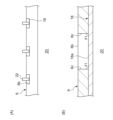
- FIG. 4(A) is a plan view of the electrode sheet.
- FIG. 4(B) is a cross-sectional view taken along line AA in FIG. 4(A).
- FIG. 5(A) is a plan view of an electrode sheet to which current collection leads are joined.
- FIG. 5(B) is an enlarged sectional view of the window portion.
- FIG. 1 is a schematic diagram of a forming apparatus 1 for a mixture sheet 6 according to an embodiment.
- the forming apparatus 1 for forming the mixture sheet 6 includes a support roll 2 and a forming roll 4.
- the support roll 2 supports the mixture sheet 6 on its peripheral surface 2a.
- the mixture sheet 6, as an example, has a long strip shape in the transport direction, and is laminated on a current collector plate and then separated into a plurality of electrode plates for use in power storage devices such as secondary batteries and capacitors.
- the mixture sheet 6 is formed, for example, as follows. That is, powder of the dry electrode mixture, which is a raw material for the mixture sheet 6, is supplied from a known storage part such as a hopper to the gap between the pair of compression rolls. The pair of compression rolls rotate in opposite directions and compress the dry electrode mixture supplied into the gap into a sheet. As a result, the mixture sheet 6 is formed.
- the mixture sheet 6 is continuously fed out from the gap between the pair of compression rolls.
- the support roll 2 is located on the downstream side of the pair of compression rolls, and conveys the mixture sheet 6 downstream by its own rotation while supporting the mixture sheet 6 on its peripheral surface 2a. Note that the mixture sheet 6 may be stretched during the conveyance process until it reaches a target thickness.
- the dry electrode mixture contains an electrode active material and, if necessary, a conductive agent and a binding material (binder).
- the electrode active material is lithium cobalt oxide, lithium iron phosphate, etc. for the positive electrode, and graphite, etc. for the negative electrode.
- the conductive agent is graphite, carbon black, acetylene black, or the like.
- the binder is polytetrafluoroethylene (PTFE), polyvinylidene fluoride (PVdF), or the like.
- the dry electrode mixture has a solvent content of 5% by mass or less, or 3% by mass or less, or even 0% by mass based on the total mass of the dry electrode mixture. Therefore, the drying oven for the mixture sheet 6 can be omitted. Note that the dry electrode mixture may contain a very small amount of solvent to the extent that a drying oven can be omitted.
- the posture of the forming roll 4 is determined so that the axis of rotation is parallel to the axis of rotation of the support roll 2.
- the circumferential surface 4a faces the circumferential surface 2a of the support roll 2 with a predetermined distance therebetween. Further, the forming roll 4 rotates together with the support roll 2.
- the support roll 2 and the forming roll 4 rotate in opposite directions. As an example, the support roll 2 and the forming roll 4 rotate at the same rotational speed.
- the forming roll 4 has a forming unit 7 composed of a cutting jig 8, a removal pad 10, and an elastic body 12 on its peripheral surface 4a.
- the forming roll 4 rotates together with the support roll 2 and presses the cutting jig 8 against the mixture sheet 6 supported by the support roll 2. As a result, the mixture sheet 6 is partially cut. Then, the forming roll 4 attaches the cut portion 6a of the mixture sheet 6 to the surface of the removal pad 10 and separates it from the mixture sheet 6. By removing the cut portion 6a, a through hole that penetrates the mixture sheet 6 in the thickness direction is formed in the mixture sheet 6. This through hole constitutes the window portion 6b.
- FIG. 2 is an exploded perspective view of the molding unit 7.
- FIG. 3 is a sectional view of the molding unit 7. Note that in FIG. 3, illustration of the mixture sheet 6 is omitted.
- the cutting jig 8 has a frame shape.
- the cutting jig 8 of this embodiment has a rectangular frame shape and includes a first cutting blade 14a to a fourth cutting blade 14d combined in a rectangular shape.
- the first cutting blade 14a and the second cutting blade 14b are arranged at a predetermined interval in the circumferential direction of the forming roll 4 and extend in the axial direction of the forming roll 4. In the rotation direction A of the forming roll 4, the first cutting blade 14a is located on the leading end side, and the second cutting blade 14b is located on the rear end side.
- the third cutting blade 14c and the fourth cutting blade 14d are lined up at a predetermined interval in the axial direction of the forming roll 4, and extend in the circumferential direction of the forming roll 4.
- the cutting edges of the first cutting blade 14a and the second cutting blade 14b extend linearly.
- the cutting edges of the third cutting blade 14c and the fourth cutting blade 14d extend in a curved shape parallel to the circumferential surface 4a.
- Each blade faces radially outward of the forming roll 4.
- the cutting jig 8 may have a frame shape such as a rectangle with rounded corners, a perfect circle, or an ellipse.
- the removal pad 10 is placed within the frame of the cutting jig 8. Therefore, when viewed from the radial direction of the forming roll 4, the removal pad 10 is surrounded by the first cutting blade 14a to the fourth cutting blade 14d.
- the surface 10a of the removal pad 10 facing the support roll 2 has a larger surface roughness than the peripheral surface 2a of the support roll 2.
- the arithmetic mean roughness Ra of the surface 10a is larger than the arithmetic mean roughness Ra of the peripheral surface 2a.
- the surface roughness of the surface 10a can be increased by known roughening treatment such as sandblasting.
- the elastic body 12 supports the removal pad 10.
- the elastic body 12 can be composed of a known spring, sponge, or the like.
- the elastic body 12 of this embodiment is formed of a coil spring, for example, and is arranged between the cutting jig 8 and the removal pad 10.
- the cutting jig 8 has a pedestal 16 within the frame. The end of the elastic body 12 on the cutting jig 8 side is fixed to the pedestal 16. The end of the elastic body 12 on the removal pad 10 side is fixed to the back surface of the removal pad 10.
- the elastic body 12 urges the removal pad 10 toward the cutting portion 6a by its own elastic force in a state where the removal pad 10 faces the support roll 2.
- the removal pad 10 when the removal pad 10 is separated from the support roll 2 due to the rotation of the support roll 2 and the forming roll 4, the removal pad 10 is drawn toward the forming roll 4 by its own elastic force.
- the elastic body 12 functions similarly to the popping member of a punching die.
- the removal pad 10 itself may have elasticity. In this case, the removal pad 10 also serves as the elastic body 12.
- the tip of the cutting jig 8 in the rotation direction A of the forming roll 4 protrudes from the tip of the removal pad 10 toward the support roll 2 side.
- the rear end portion of the cutting jig 8 in the rotation direction A protrudes from the rear end portion of the removal pad 10 toward the support roll 2 side. That is, the cutting edges of the first cutting blade 14a and the second cutting blade 14b each protrude toward the support roll 2 side from the surface 10a of the removal pad 10.
- the intermediate portion of the removal pad 10 in the rotation direction A protrudes from the intermediate portion of the cutting jig 8 toward the support roll 2 side.
- the surface 10a of the removal pad 10 protrudes more toward the support roll 2 than the third cutting blade 14c and the fourth cutting blade 14d.
- the surface 10a of the removal pad 10 has a curved shape with a larger curvature than the peripheral surface 4a of the forming roll 4.
- the forming unit 7 approaches the peripheral surface 2a of the support roll 2 as the forming roll 4 rotates.
- the first cutting blade 14a is pressed against the mixture sheet 6. Since the cutting jig 8 protrudes beyond the removal pad 10 at the tip in the rotation direction A, the first cutting blade 14a can be more reliably applied to the mixture sheet 6.
- the first cutting blade 14a cuts the mixture sheet 6, a starting point of the cutting portion 6a is formed.
- the surface 10a of the removal pad 10 comes into contact with the mixture sheet 6, and the surface 10a is pressed against the mixture sheet 6 by the urging force of the elastic body 12. Further, the removal pad 10 sinks into the frame of the cutting jig 8 due to the reaction force of the mixture sheet 6. Thereby, the third cutting blade 14c and the fourth cutting blade 14d are pressed against the mixture sheet 6. When the third cutting blade 14c and the fourth cutting blade 14d cut the mixture sheet 6, the cutting portion 6a extends rearward in the rotation direction A.
- the cut portion 6a is transferred onto the surface 10a of the removal pad 10 from the tip side in the rotation direction A.
- the cut portion 6a can be easily transferred to the removal pad 10. Further, by pressing the surface 10a against the cut portion 6a with the elastic body 12, the cut portion 6a can be easily transferred to the removal pad 10.
- the second cutting blade 14b is pressed against the mixture sheet 6. Since the cutting jig 8 protrudes beyond the removal pad 10 at the rear end in the rotational direction A, the second cutting blade 14b can be more reliably applied to the mixture sheet 6.
- the second cutting blade 14b cuts the mixture sheet 6, the end point of the cut portion 6a is formed. Thereby, the cut portion 6a becomes rectangular.
- the removal pad 10 separates from the peripheral surface 2a of the support roll 2.
- the cut portion 6a transferred to the removal pad 10 is separated from the mixture sheet 6.
- the removal pad 10 is pulled toward the support roll 2 via the cut portion 6a.
- the removal pad 10 is pulled toward the forming roll 4 by a force stronger than the force pulled toward the support roll 2 by the elastic body 12 . Thereby, the cut portion 6a can be separated from the mixture sheet 6 more reliably.
- the cutting jig 8 is fixed to the forming roll 4. Therefore, compared to a structure in which the cutting jig 8 is displaced in the radial direction of the forming roll 4, the structure of the forming unit 7 can be simplified. Furthermore, maintenance of the forming roll 4 becomes easier. Furthermore, in this embodiment, the window portion 6b is formed before the mixture sheet 6 is laminated on the current collector plate. This makes it possible to prevent the current collector plate from being cut out by the cutting jig 8. Therefore, it is possible to improve the quality of the power storage device.
- the cut portion 6a separated from the mixture sheet 6 is peeled off and removed from the removal pad 10 by a peeling mechanism (not shown) at a predetermined position.
- the molding unit 7 from which the cutting portion 6a has been removed advances to a position facing the support roll 2 again by the rotation of the molding roll 4, and is subjected to the cutting process of the mixture sheet 6.
- a plurality of windows 6b are formed in the mixture sheet 6 at predetermined intervals in the transport direction.
- each window portion 6b is arranged at the center of the mixture sheet 6 in the width direction (direction perpendicular to the conveyance direction).
- the forming roll 4 shown in FIG. 1 has only one forming unit 7, the number of forming units 7 is not limited to one.
- the forming roll 4 may have a plurality of forming units 7 depending on the interval between the windows 6b formed in the mixture sheet 6. Furthermore, the interval between the window portions 6b may be adjusted by the interval between the plurality of forming units 7, or by the radius of the forming roll 4.
- FIG. 4(A) is a plan view of the electrode sheet 20.
- FIG. 4(B) is a cross-sectional view taken along line AA in FIG. 4(A).
- the mixture sheet 6 having the window portion 6b is conveyed downstream by the support roll 2.
- the mixture sheet 6 is then laminated on the surface of the current collector plate 18 to obtain the electrode sheet 20.
- the electrode sheet 20 is a continuous body of a plurality of dry electrode plates.
- mixture sheets 6 are laminated on both sides of current collector plate 18 .
- the current collector plate 18 is made of aluminum foil or the like if it is a positive electrode, and is made of copper foil or the like if it is a negative electrode.
- the current collector plate 18 is exposed at the window portion 6b.
- each window portion 6b is surrounded by a dry electrode mixture. Therefore, the current collector plate 18 is exposed in spots.
- the exposed portion of the current collector plate 18, that is, the portion to which the electrode mixture is not applied extends across the entire width of the electrode sheet.
- the exposed portion of the current collector plate 18 extends only in a part of the electrode sheet 20 in the width direction. Therefore, the amount of dry electrode mixture on each electrode plate can be increased. Therefore, it is possible to increase the capacity of the power storage device. Furthermore, since the exposed portion of the current collector plate 18 can be made smaller, the safety of the power storage device can also be improved.
- FIG. 5(A) is a plan view of the electrode sheet 20 to which the current collection leads 22 are bonded.
- FIG. 5(B) is an enlarged sectional view of the window portion 6b. Note that the cross section shown in FIG. 5(B) is a cross section of the electrode sheet 20 perpendicular to the extending direction of the current collector plate 18 and the mixture sheet 6, in other words, the normal line of the current collector plate 18 and the mixture sheet 6. It is a cross section parallel to . Further, in FIG. 5(B), illustration of one of the mixture sheets 6 is omitted.
- the electrode sheet 20 is cut at the center in the width direction and divided into two, as shown in FIG. 5(A). As a result, each window portion 6b is also divided into two. As a result, each rectangular window portion 6b is surrounded on three sides by the dry electrode mixture. Then, a current collecting lead 22 (current collecting tab) is joined by welding or the like to a portion of the current collecting plate 18 exposed from each divided window portion 6b. The exposed portion of the current collector plate 18 to which the current collector leads 22 are bonded is covered with an insulating protective tape (not shown). Thereafter, the electrode sheet 20 is cut between adjacent current collecting leads 22 to separate into a plurality of dry electrode plates.
- the side wall 6c (the side surface connecting the two main surfaces) of the mixture sheet 6 at the window portion 6b.
- the angle ⁇ 1 formed with the surface 18a of the current collector plate 18 is 75° or more and 105° or less.
- the angle ⁇ 1 is 75° to 105° around the entire circumference of the window portion 6b.
- the angle ⁇ 1 is 85° or more and 95° or less.
- the angle ⁇ 1 between the side wall 6c and the surface 18a of the current collecting plate 18 is approximately a right angle of 75° or more and 105° or less.
- poor bonding between the current collecting plate 18 and the current collecting lead 22 due to interference of the dry electrode mixture can be prevented. It can be easily suppressed. Further, contact between the current collection lead 22 and the dry electrode mixture can be easily suppressed. With these, it is possible to improve the quality of the power storage device. In particular, if the unapplied portions of the dry electrode mixture become spots, it becomes difficult to join the current collecting leads 22. Therefore, the effect of improving the quality of the power storage device by making the angle ⁇ 1 substantially right angle is more likely to be exhibited.
- the boundary between the uncoated area and the coated area of the wet electrode mixture may be distorted due to sagging of the wet electrode mixture.
- the edges of the applied area may become jagged.
- the separator may be damaged when the electrode plate repeatedly expands and contracts due to charging and discharging of the power storage device. Damage to the separator can cause an internal short circuit.
- the window portion 6b is formed by cutting the mixture sheet 6 made of the dry electrode mixture with the cutting jig 8. Therefore, the boundary between the uncoated part and the coated part of the dry electrode mixture is not easily distorted, and the above-mentioned angle ⁇ 1 can be maintained at a substantially right angle. Moreover, the edge of the application part is linear in accordance with the shape of the cutting blade. Therefore, damage to the separator can also be suppressed. Furthermore, since the window portion 6b is formed by cutting with the cutting jig 8, it is possible to suppress the edges of the application portion from rising in the thickness direction of the mixture sheet 6. This also suppresses damage to the separator when the electrode plate repeatedly expands and contracts due to charging and discharging of the power storage device.
- Embodiments may be specified by the items described below.
- a support roll (2) that supports a mixture sheet (6) made of a dry electrode mixture on a peripheral surface (2a); It has a frame-shaped cutting jig (8) and a removal pad (10) disposed within the frame of the cutting jig (8) on its circumferential surface (4a), and the circumferential surface (4a) is attached to the supporting roll (2).
- a forming roll (4) that faces the circumferential surface (2a) of the mold at a predetermined distance and rotates with the rotation of the support roll (2);
- the forming roll (4) partially cuts the mixture sheet (6) by pressing the cutting jig (8) against the mixture sheet (6), and removes the cut portion (6a) from the surface of the removal pad (10). (10a) and separate it from the mixture sheet (6).
- the surface (10a) of the removal pad (10) has a larger surface roughness than the peripheral surface (2a) of the support roll (2). Molding device (1) according to the first item.
- the forming roll (4) has an elastic body (12) that supports the removal pad (10).
- the molding device (1) according to the first item or the second item. [4th item]
- the tip of the cutting jig (8) in the rotation direction (A) of the forming roll (4) protrudes from the tip of the removal pad (10) toward the support roll (2)
- the rear end of the cutting jig (8) in the rotation direction (A) protrudes from the rear end of the removal pad (10) toward the support roll (2)
- the middle part of the removal pad (10) in the rotation direction (A) protrudes toward the support roll (2) from the middle part of the cutting jig (8).
- the molding device (1) according to any one of the first to third items.
- a mixture sheet (6) composed of a dry electrode mixture is supported on the peripheral surface (2a) of the support roll (2), It has a frame-shaped cutting jig (8) and a removal pad (10) disposed within the frame of the cutting jig (8) on its circumferential surface (4a), and the circumferential surface (4a) is attached to the supporting roll (2). ) is rotated together with the support roll (2), and the forming roll (4) facing the peripheral surface (2a) of the The cutting jig (8) is pressed against the mixture sheet (6) to partially cut the mixture sheet (6), and the cut portion (6a) is attached to the surface (10a) of the removal pad (10). including separating it from the mixture sheet (6); Method for forming mixture sheet (6).
- An electrode sheet (20) comprising a current collector plate (18) and a mixture sheet (6) composed of a dry electrode mixture and laminated on the surface of the current collector plate (18),
- the mixture sheet (6) has a window (6b) surrounded by the dry electrode mixture all around, and the current collector plate (18) is exposed in the window (6b).
- the side wall (6c) of the mixture sheet (6) in the window portion (6b) and the surface of the current collector plate (18) The angle ( ⁇ 1) formed with (18a) is 75° or more and 105° or less, Electrode sheet (20).
- the present disclosure can be used in a molding device and a molding method for a mixture sheet.
- Forming device 2. Support roll, 4. Forming roll, 6. Mixture sheet, 6a. Cutting section, 6b. Window section, 6c. Side wall, 8. Cutting jig, 10. Removal pad, 12. Elastic body, 18. Current collector plate. 20 Electrode sheet.
Abstract
合剤シート6の成形装置1は、乾式電極合剤で構成される合剤シート6を周面2aで支持する支持ロール2と、枠状の切断治具8、および切断治具8の枠内に配置される除去パッド10を周面4aに有し、当該周面4aが支持ロール2の周面2aと所定の間隔をあけて対向し、支持ロール2とともに回転する成形ロール4とを備える。成形ロール4は、切断治具8を合剤シート6に押し当てて合剤シート6を部分的に切断し、切断部6aを除去パッド10の表面に付着させて合剤シート6から引き離す。
Description
本開示は、合剤シートの成形装置および成形方法に関する。
特許文献1には、一対の圧縮ロールの隙間に粒体を供給し、シート状に圧縮して塗膜を形成し、この塗膜を基材に積層する装置が記載されている。この装置は、周面に刃が設けられた段付きロールを備え、塗膜の一部を段付きロールで除去している。また、特許文献1には、二次電池やキャパシタ等の蓄電装置に用いられる機能性シートをこの装置で製造することが記載されている。また、基材として集電板が例示され、塗料として電極合剤が例示されている。
上述した装置で電極合剤シートを集電板に積層して電極シートを製造する場合、電極合剤シートの一部を除去することで、集電板の露出部を形成することができる。この露出部は、集電リードの接続部等に利用することができる。
蓄電装置を高容量化したいという要求は常に存在する。本発明者らは鋭意検討の結果、従来の装置には蓄電装置の高容量化を図る上で改善の余地があることを認識するに至った。
本開示はこうした状況に鑑みてなされたものであり、その目的は、蓄電装置の高容量化を図るための技術を提供することにある。
本開示のある態様は、合剤シートの成形装置である。この装置は、乾式電極合剤で構成される合剤シートを周面で支持する支持ロールと、枠状の切断治具、および切断治具の枠内に配置される除去パッドを周面に有し、当該周面が支持ロールの周面と所定の間隔をあけて対向し、支持ロールとともに回転する成形ロールと、を備える。成形ロールは、切断治具を合剤シートに押し当てて合剤シートを部分的に切断し、切断部を除去パッドの表面に付着させて合剤シートから引き離す。
本開示の他の態様は、合剤シートの成形方法である。この方法は、乾式電極合剤で構成される合剤シートを支持ロールの周面で支持し、枠状の切断治具、および切断治具の枠内に配置される除去パッドを周面に有し、当該周面が支持ロールの周面と所定の間隔をあけて対向する成形ロールを支持ロールとともに回転させ、切断治具を合剤シートに押し当てて合剤シートを部分的に切断し、切断部を除去パッドの表面に付着させて合剤シートから引き離すことを含む。
以上の構成要素の任意の組合せ、本開示の表現を方法、装置、システムなどの間で変換したものもまた、本開示の態様として有効である。
本開示によれば、蓄電装置の高容量化を図ることができる。
以下、本開示を好適な実施の形態をもとに図面を参照しながら説明する。実施の形態は、本開示を限定するものではなく例示であって、実施の形態に記述されるすべての特徴やその組み合わせは、必ずしも本開示の本質的なものであるとは限らない。各図面に示される同一または同等の構成要素、部材、処理には、同一の符号を付するものとし、適宜重複した説明は省略する。また、各図に示す各部の縮尺や形状は、説明を容易にするために便宜的に設定されており、特に言及がない限り限定的に解釈されるものではない。また、本明細書または請求項中に「第1」、「第2」等の用語が用いられる場合には、特に言及がない限りこの用語はいかなる順序や重要度を表すものでもなく、ある構成と他の構成とを区別するためのものである。また、各図面において実施の形態を説明する上で重要ではない部材の一部は省略して表示する。
図1は、実施の形態に係る合剤シート6の成形装置1の模式図である。合剤シート6の成形装置1は、支持ロール2と、成形ロール4とを備える。支持ロール2は、合剤シート6を周面2aで支持する。一例としての合剤シート6は、搬送方向に長い帯状であり、集電板に積層された後に複数の電極板に個片化されて二次電池やキャパシタ等の蓄電装置に用いられる。合剤シート6は、例えば以下の様にして形成される。すなわち、ホッパー等の公知の貯留部から、合剤シート6の原材料となる乾式電極合剤の粉体が一対の圧縮ロールの隙間に供給される。一対の圧縮ロールは、互いに逆方向に回転し、隙間に供給された乾式電極合剤をシート状に圧縮する。これにより、合剤シート6が成形される。
合剤シート6は、一対の圧縮ロールの隙間から連続的に送り出される。支持ロール2は、一対の圧縮ロールの下流側に位置し、合剤シート6を周面2aで支持しながら自身の回転によって合剤シート6を下流側に搬送する。なお、合剤シート6は、搬送の過程で目標厚みとなるまで延伸されてもよい。
乾式電極合剤は、電極活物質と、必要に応じて導電剤および結着材(バインダ)とを含む。一般的なリチウムイオン二次電池の場合、電極活物質は、正極であればコバルト酸リチウムやリン酸鉄リチウム等であり、負極であれば黒鉛等である。また、導電剤は、黒鉛、カーボンブラック、アセチレンブラック等である。結着材は、ポリテトラフルオロエチレン(PTFE)、ポリフッ化ビニリデン(PVdF)等である。また、乾式電極合剤は、溶媒の含有量が乾式電極合剤の全質量に対して5質量%以下、あるいは3質量%以下、さらには0質量%である。したがって、合剤シート6の乾燥炉を省略することができる。なお、乾式電極合剤は、乾燥炉を省略できる程度に極少量の溶媒を含有してもよい。
成形ロール4は、回転軸が支持ロール2の回転軸と平行になるよう姿勢が定められる。そして、周面4aが支持ロール2の周面2aと所定の間隔をあけて対向する。また、成形ロール4は、支持ロール2とともに回転する。支持ロール2および成形ロール4は、互いに逆方向に回転する。一例として、支持ロール2および成形ロール4は、同じ回転速度で回転する。
成形ロール4は、切断治具8、除去パッド10および弾性体12で構成される成形ユニット7を周面4aに有する。成形ロール4は、支持ロール2とともに回転して、支持ロール2が支持する合剤シート6に切断治具8を押し当てる。これにより、合剤シート6が部分的に切断される。そして、成形ロール4は、合剤シート6の切断部6aを除去パッド10の表面に付着させて合剤シート6から引き離す。切断部6aが除去されることで、合剤シート6には合剤シート6を厚み方向に貫通する貫通孔が形成される。この貫通孔は、窓部6bを構成する。
図2は、成形ユニット7の分解斜視図である。図3は、成形ユニット7の断面図である。なお、図3では合剤シート6の図示を省略している。図2に示すように、切断治具8は、枠状である。本実施の形態の切断治具8は矩形の枠状であり、矩形に組み合わされた第1切断刃14a~第4切断刃14dを有する。第1切断刃14aおよび第2切断刃14bは、成形ロール4の周方向に所定の間隔をあけて並び、成形ロール4の軸方向に延びる。成形ロール4の回転方向Aにおいて、第1切断刃14aは先端側に位置し、第2切断刃14bは後端側に位置する。第3切断刃14cおよび第4切断刃14dは、成形ロール4の軸方向に所定の間隔をあけて並び、成形ロール4の周方向に延びる。第1切断刃14aおよび第2切断刃14bの刃先は、直線状に延びる。第3切断刃14cおよび第4切断刃14dの刃先は、周面4aと平行に曲線状に延びる。各刃は成形ロール4の半径方向外側を向く。なお、切断治具8は、角の丸い矩形、真円、楕円等の枠状であってもよい。
除去パッド10は、切断治具8の枠内に配置される。したがって、成形ロール4の半径方向から見て、除去パッド10は、第1切断刃14a~第4切断刃14dで囲まれている。除去パッド10の支持ロール2と対向する表面10aは、支持ロール2の周面2aよりも表面粗さが大きい。例えば、表面10aの算術平均粗さRaは、周面2aの算術平均粗さRaよりも大きい。表面10aの表面粗さは、サンドブラスト処理等の公知の粗化処理によって大きくすることができる。
弾性体12は、除去パッド10を支持する。弾性体12は、公知のスプリングやスポンジ等で構成することができる。本実施の形態の弾性体12は、一例としてコイルスプリングで構成され、切断治具8と除去パッド10との間に配置される。切断治具8は、枠内に台座16を有する。弾性体12の切断治具8側の端部は、台座16に固定される。弾性体12の除去パッド10側の端部は、除去パッド10の裏面に固定される。弾性体12は、除去パッド10が支持ロール2と対向する状態で、自身の弾性力によって除去パッド10を切断部6a側に付勢する。また、支持ロール2および成形ロール4の回転により除去パッド10が支持ロール2から離間する際に、自身の弾性力によって除去パッド10を成形ロール4側に引き寄せる。弾性体12は、抜き型の跳ね出し部材と同様の働きをする。なお、除去パッド10自体が弾性を有してもよい。この場合は、除去パッド10が弾性体12を兼ねる。
図3に示すように、成形ロール4の回転方向Aにおける切断治具8の先端部は、除去パッド10の先端部より支持ロール2側に突出している。また、回転方向Aにおける切断治具8の後端部は、除去パッド10の後端部より支持ロール2側に突出している。つまり、第1切断刃14aおよび第2切断刃14bの刃先はそれぞれ、除去パッド10の表面10aよりも支持ロール2側に突出している。一方、回転方向Aにおける除去パッド10の中間部は、切断治具8の中間部より支持ロール2側に突出している。つまり、回転方向Aにおける除去パッド10の中間点を含む少なくとも一部の領域において、除去パッド10の表面10aは、第3切断刃14cおよび第4切断刃14dより支持ロール2側に突出している。一例として、除去パッド10の表面10aは、成形ロール4の周面4aより曲率の大きい曲面形状を有する。
成形ユニット7は、成形ロール4の回転にともなって支持ロール2の周面2aに接近していく。そして、始めに第1切断刃14aが合剤シート6に押し当てられる。切断治具8は、回転方向Aの先端部において除去パッド10よりも突出しているため、第1切断刃14aをより確実に合剤シート6に当てることができる。第1切断刃14aが合剤シート6を切断することで、切断部6aの始点が形成される。
成形ロール4がさらに回転すると、除去パッド10の表面10aが合剤シート6に当接し、弾性体12の付勢力によって表面10aが合剤シート6に押し付けられる。また、除去パッド10は、合剤シート6の反力を受けて切断治具8の枠内に沈み込む。これにより、第3切断刃14cおよび第4切断刃14dが合剤シート6に押し当てられる。第3切断刃14cおよび第4切断刃14dが合剤シート6を切断することで、切断部6aが回転方向Aの後方に延びていく。
切断部6aは、回転方向Aの先端側から除去パッド10の表面10aに転写されていく。除去パッド10の表面10aの表面粗さを支持ロール2の周面2aの表面粗さより大きくすることで、切断部6aを除去パッド10に転写させやすくすることができる。また、弾性体12によって表面10aを切断部6aに押し付けることでも、切断部6aを除去パッド10に転写させやすくすることができる。
そして、成形ロール4がさらに回転すると、第2切断刃14bが合剤シート6に押し当てられる。切断治具8は、回転方向Aの後端部において除去パッド10よりも突出しているため、第2切断刃14bをより確実に合剤シート6に当てることができる。第2切断刃14bが合剤シート6を切断することで、切断部6aの終点が形成される。これにより、切断部6aが矩形状となる。
成形ロール4がさらに回転すると、除去パッド10が支持ロール2の周面2aから離間していく。これにより、除去パッド10に転写された切断部6aは、合剤シート6から引き離される。除去パッド10が周面2aから離間していく際、除去パッド10は切断部6aを介して支持ロール2側に引っ張られる。しかしながら、除去パッド10は、弾性体12によって支持ロール2側に引っ張られる力よりも強い力で成形ロール4側に引き寄せられる。これにより、切断部6aをより確実に合剤シート6から引き離すことができる。
切断治具8は、成形ロール4に固定されている。したがって、切断治具8を成形ロール4の半径方向に変位させる構造に比べて、成形ユニット7の構造を簡素化できる。また、成形ロール4のメンテナンスが容易になる。また、本実施の形態では、合剤シート6が集電板に積層される前に窓部6bが形成される。これにより、切断治具8によって集電板が切り欠かれることを回避することができる。よって、蓄電装置の品質向上を図ることができる。
合剤シート6から切り離された切断部6aは、所定の位置において図示しない剥離機構により除去パッド10から剥離されて除去される。切断部6aが除去された成形ユニット7は、成形ロール4の回転により再び支持ロール2と対向する位置まで進み、合剤シート6の切断処理に供される。これにより、合剤シート6には、搬送方向に所定の間隔で並ぶ複数の窓部6bが形成される。一例として各窓部6bは、合剤シート6の幅方向(搬送方向に直交する方向)の中央に配置される。
図1に示す成形ロール4は、成形ユニット7を1つだけ有するが、成形ユニット7の数は1つに限定されない。成形ロール4は、合剤シート6に形成する窓部6bの間隔に応じて複数の成形ユニット7を有してもよい。また、窓部6bの間隔は、複数の成形ユニット7の間隔によって調整されてもよいし、成形ロール4の半径によって調整されてもよい。
図4(A)は、電極シート20の平面図である。図4(B)は、図4(A)のA-A線に沿った断面図である。窓部6bを有する合剤シート6は、支持ロール2によって下流側に搬送される。そして、合剤シート6が集電板18の表面に積層されて、電極シート20が得られる。電極シート20は、複数の乾式電極板の連続体である。一例として、集電板18の両面に合剤シート6が積層される。一般的なリチウムイオン二次電池の場合、集電板18は、正極であればアルミニウム箔等で構成され、負極であれば銅箔等で構成される。集電板18は、窓部6bにおいて露出する。
各窓部6bは、全周が乾式電極合剤で囲まれている。したがって、集電板18は、スポット状に露出する。従来の電極シートでは、集電板18の露出部、つまり電極合剤の未塗布部が電極シートの幅方向の全体に延在していた。これに対し、本実施の形態の電極シート20では、集電板18の露出部が電極シート20の幅方向の一部のみに延在する。これにより、各電極板における乾式電極合剤の量を増やすことができる。よって、蓄電装置の高容量化を図ることができる。また、集電板18の露出部を小さくできるため、蓄電装置の安全性も高めることができる。
図5(A)は、集電リード22が接合された電極シート20の平面図である。図5(B)は、窓部6bの拡大断面図である。なお、図5(B)に示す断面は、電極シート20における、集電板18および合剤シート6の延在方向と直交する断面、換言すれば集電板18および合剤シート6の法線に平行な断面である。また、図5(B)では、一方の合剤シート6の図示を省略している。
一例として電極シート20は、図5(A)に示すように、幅方向の中央で切断されて2つに分割される。これにより、各窓部6bも2つに分割される。この結果、矩形状の各窓部6bは、三方が乾式電極合剤で囲まれた状態となる。そして、集電板18における、分割された各窓部6bから露出する部分に、集電リード22(集電タブ)が溶接等により接合される。集電リード22が接合された集電板18の露出部は、絶縁性の保護テープ(図示せず)で覆われる。その後、電極シート20は、隣り合う集電リード22の間で切断されて、複数の乾式電極板に個片化される。
図5(B)に示すように、集電板18および合剤シート6の延在方向と直交する断面において、窓部6bにおける合剤シート6の側壁6c(2つの主表面をつなぐ側面)と、集電板18の表面18aとのなす角度θ1は、75°以上105°以下である。好ましくは、窓部6bの全周において、角度θ1は75°~105°である。また好ましくは、角度θ1は85°以上95°以下である。側壁6cと集電板18の表面18aとのなす角度θ1を75°以上105°以下のおおよそ直角とすることで、乾式電極合剤の干渉による集電板18および集電リード22の接合不良を抑制しやすくすることができる。また、集電リード22と乾式電極合剤との接触を抑制しやすくすることができる。これらにより、蓄電装置の品質向上を図ることができる。特に、乾式電極合剤の未塗布部がスポット状になると、集電リード22の接合作業が困難になる。よって、角度θ1をほぼ直角にすることによる蓄電装置の品質向上効果がより発揮されやすい。
また、湿式電極合剤で合剤シートが構成される場合は、湿式電極合剤のダレによって、湿式電極合剤の未塗布部と塗布部との境界が歪み得る。また、湿式電極合剤を間欠塗工して未塗布部を形成する場合、塗布部の縁がギザギザ状になり得る。この場合、蓄電装置の充放電により電極板が膨張収縮を繰り返した際にセパレータが損傷し得る。セパレータの損傷は、内部短絡を引き起こし得る。
これに対し、本実施の形態では、乾式電極合剤で構成される合剤シート6を切断治具8で切断して窓部6bを形成している。このため、乾式電極合剤の未塗布部と塗布部との境界が歪み難く、上述した角度θ1をほぼ直角に維持することができる。また、塗布部の縁は、切断刃の形状に合わせて直線状となる。このため、セパレータの損傷も抑制することができる。また、切断治具8での切断により窓部6bを形成するため、合剤シート6の厚み方向に塗布部の縁が盛り上がることを抑制できる。これによっても、蓄電装置の充放電により電極板が膨張収縮を繰り返した際にセパレータが損傷することを抑制できる。
以上、本開示の実施の形態について詳細に説明した。前述した実施の形態は、本開示を実施するにあたっての具体例を示したものにすぎない。実施の形態の内容は、本開示の技術的範囲を限定するものではなく、請求の範囲に規定された本開示の思想を逸脱しない範囲において、構成要素の変更、追加、削除等の多くの設計変更が可能である。設計変更が加えられた新たな実施の形態は、組み合わされる実施の形態および変形それぞれの効果をあわせもつ。前述の実施の形態では、このような設計変更が可能な内容に関して、「本実施の形態の」、「本実施の形態では」等の表記を付して強調しているが、そのような表記のない内容でも設計変更が許容される。各実施の形態に含まれる構成要素の任意の組み合わせも、本開示の態様として有効である。図面の断面に付したハッチングは、ハッチングを付した対象の材質を限定するものではない。
実施の形態は、以下に記載する項目によって特定されてもよい。
[第1項目]
乾式電極合剤で構成される合剤シート(6)を周面(2a)で支持する支持ロール(2)と、
枠状の切断治具(8)、および切断治具(8)の枠内に配置される除去パッド(10)を周面(4a)に有し、当該周面(4a)が支持ロール(2)の周面(2a)と所定の間隔をあけて対向し、支持ロール(2)の回転とともに回転する成形ロール(4)と、を備え、
成形ロール(4)は、切断治具(8)を合剤シート(6)に押し当てて合剤シート(6)を部分的に切断し、切断部(6a)を除去パッド(10)の表面(10a)に付着させて合剤シート(6)から引き離す、
合剤シート(6)の成形装置(1)。
[第2項目]
除去パッド(10)の表面(10a)は、支持ロール(2)の周面(2a)よりも表面粗さが大きい、
第1項目に記載の成形装置(1)。
[第3項目]
成形ロール(4)は、除去パッド(10)を支持する弾性体(12)を有する、
第1項目または第2項目に記載の成形装置(1)。
[第4項目]
成形ロール(4)の回転方向(A)における切断治具(8)の先端部は、除去パッド(10)の先端部より支持ロール(2)側に突出し、
回転方向(A)における切断治具(8)の後端部は、除去パッド(10)の後端部より支持ロール(2)側に突出し、
回転方向(A)における除去パッド(10)の中間部は、切断治具(8)の中間部より支持ロール(2)側に突出する、
第1項目乃至第3項目のいずれかに記載の成形装置(1)。
[第5項目]
乾式電極合剤で構成される合剤シート(6)を支持ロール(2)の周面(2a)で支持し、
枠状の切断治具(8)、および切断治具(8)の枠内に配置される除去パッド(10)を周面(4a)に有し、当該周面(4a)が支持ロール(2)の周面(2a)と所定の間隔をあけて対向する成形ロール(4)を支持ロール(2)とともに回転させ、
切断治具(8)を合剤シート(6)に押し当てて合剤シート(6)を部分的に切断し、切断部(6a)を除去パッド(10)の表面(10a)に付着させて合剤シート(6)から引き離すことを含む、
合剤シート(6)の成形方法。
[第6項目]
集電板(18)と、乾式電極合剤で構成されて集電板(18)の表面に積層された合剤シート(6)と、を備える電極シート(20)であって、
合剤シート(6)は、全周が乾式電極合剤で囲まれた窓部(6b)を有し、窓部(6b)において集電板(18)が露出し、
集電板(18)および合剤シート(6)の延在方向と直交する断面において、窓部(6b)における合剤シート(6)の側壁(6c)と、集電板(18)の表面(18a)とのなす角度(θ1)が75°以上105°以下である、
電極シート(20)。
本開示は、合剤シートの成形装置および成形方法に利用することができる。
1 成形装置、 2 支持ロール、 4 成形ロール、 6 合剤シート、 6a 切断部、 6b 窓部、 6c 側壁、 8 切断治具、 10 除去パッド、 12 弾性体、 18 集電板、 20 電極シート。
Claims (5)
- 乾式電極合剤で構成される合剤シートを周面で支持する支持ロールと、
枠状の切断治具、および前記切断治具の枠内に配置される除去パッドを周面に有し、当該周面が前記支持ロールの周面と所定の間隔をあけて対向し、前記支持ロールとともに回転する成形ロールと、を備え、
前記成形ロールは、前記切断治具を前記合剤シートに押し当てて前記合剤シートを部分的に切断し、切断部を前記除去パッドの表面に付着させて前記合剤シートから引き離す、
合剤シートの成形装置。 - 前記除去パッドの表面は、前記支持ロールの周面よりも表面粗さが大きい、
請求項1に記載の成形装置。 - 前記成形ロールは、前記除去パッドを支持する弾性体を有する、
請求項1または2に記載の成形装置。 - 前記成形ロールの回転方向における前記切断治具の先端部は、前記除去パッドの前記先端部より前記支持ロール側に突出し、
前記回転方向における前記切断治具の後端部は、前記除去パッドの前記後端部より前記支持ロール側に突出し、
前記回転方向における前記除去パッドの中間部は、前記切断治具の前記中間部より前記支持ロール側に突出する、
請求項1または2に記載の成形装置。 - 乾式電極合剤で構成される合剤シートを支持ロールの周面で支持し、
枠状の切断治具、および前記切断治具の枠内に配置される除去パッドを周面に有し、当該周面が前記支持ロールの周面と所定の間隔をあけて対向する成形ロールを前記支持ロールとともに回転させ、
前記切断治具を前記合剤シートに押し当てて前記合剤シートを部分的に切断し、切断部を前記除去パッドの表面に付着させて前記合剤シートから引き離すことを含む、
合剤シートの成形方法。
Applications Claiming Priority (2)
| Application Number | Priority Date | Filing Date | Title |
|---|---|---|---|
| JP2022114706 | 2022-07-19 | ||
| JP2022-114706 | 2022-07-19 |
Publications (1)
| Publication Number | Publication Date |
|---|---|
| WO2024018731A1 true WO2024018731A1 (ja) | 2024-01-25 |
Family
ID=89617412
Family Applications (1)
| Application Number | Title | Priority Date | Filing Date |
|---|---|---|---|
| PCT/JP2023/017780 WO2024018731A1 (ja) | 2022-07-19 | 2023-05-11 | 合剤シートの成形装置および成形方法 |
Country Status (1)
| Country | Link |
|---|---|
| WO (1) | WO2024018731A1 (ja) |
Citations (4)
| Publication number | Priority date | Publication date | Assignee | Title |
|---|---|---|---|---|
| JPH0473499U (ja) * | 1990-11-05 | 1992-06-26 | ||
| JPH09201798A (ja) * | 1996-01-30 | 1997-08-05 | Nippon Daisuchiile Kk | 紙器打抜装置のクッション材 |
| JPH10100098A (ja) * | 1996-09-30 | 1998-04-21 | Daisou Kk | 打抜装置 |
| JP2005001012A (ja) * | 2003-06-09 | 2005-01-06 | Nippon Tungsten Co Ltd | ロータリーカッター |
-
2023
- 2023-05-11 WO PCT/JP2023/017780 patent/WO2024018731A1/ja unknown
Patent Citations (4)
| Publication number | Priority date | Publication date | Assignee | Title |
|---|---|---|---|---|
| JPH0473499U (ja) * | 1990-11-05 | 1992-06-26 | ||
| JPH09201798A (ja) * | 1996-01-30 | 1997-08-05 | Nippon Daisuchiile Kk | 紙器打抜装置のクッション材 |
| JPH10100098A (ja) * | 1996-09-30 | 1998-04-21 | Daisou Kk | 打抜装置 |
| JP2005001012A (ja) * | 2003-06-09 | 2005-01-06 | Nippon Tungsten Co Ltd | ロータリーカッター |
Similar Documents
| Publication | Publication Date | Title |
|---|---|---|
| US7307831B2 (en) | Method of manufacturing electrode and electrode | |
| JPH07320770A (ja) | 渦巻電極体を備えた電池 | |
| WO2017014233A1 (ja) | リチウムイオン二次電池の電極組立体及びその製造方法 | |
| JP2017132019A (ja) | 電極製造装置 | |
| JP2005190787A (ja) | 非水電解質二次電池用電極板およびその製造方法 | |
| CN112670435A (zh) | 电池极片制备方法 | |
| WO2024018731A1 (ja) | 合剤シートの成形装置および成形方法 | |
| WO2024018732A1 (ja) | 電極シート | |
| JP5550091B2 (ja) | 非水電解質二次電池用電極の製造方法およびそれを用いた非水電解質二次電池 | |
| JP2023519948A (ja) | 超音波切削機を含む電極組立体製造装置及びこれを用いた電極組立体製造方法 | |
| JP2005183181A (ja) | 非水電解質二次電池用電極板およびその製造方法 | |
| US20190074550A1 (en) | Electrode assembly for secondary battery and method for producing electrode assembly for secondary battery | |
| JP2017196669A (ja) | 電極製造設備 | |
| JP2020196080A (ja) | ロータリーダイカット装置 | |
| JP2018026334A (ja) | 蓄電装置の電極、電極の製造装置及び電極の製造方法 | |
| CN111477836A (zh) | 一种电池极片制备方法及装置 | |
| JP2000012002A (ja) | 帯状電極の製造装置 | |
| CN214505544U (zh) | 一种电池极片制备装置 | |
| JP6736953B2 (ja) | 電極の製造方法及びロータリーダイカッタ | |
| JP3325227B2 (ja) | リチウムイオンポリマー型2次電池の組立製造方法 | |
| JPH11167916A (ja) | 電池用電極板の製造方法 | |
| JP2018073658A (ja) | 電極製造装置 | |
| JPH11354110A (ja) | 密閉型電池の電極板およびその製造方法 | |
| JP2001043848A (ja) | ポリマーバッテリーの製造方法および剥離装置 | |
| JP2012069279A (ja) | 電極切断装置及び電極製造方法 |
Legal Events
| Date | Code | Title | Description |
|---|---|---|---|
| 121 | Ep: the epo has been informed by wipo that ep was designated in this application |
Ref document number: 23842663 Country of ref document: EP Kind code of ref document: A1 |