WO2024014529A1 - 自律移動ロボット及び自律移動ロボットの制御システム - Google Patents
自律移動ロボット及び自律移動ロボットの制御システム Download PDFInfo
- Publication number
- WO2024014529A1 WO2024014529A1 PCT/JP2023/026015 JP2023026015W WO2024014529A1 WO 2024014529 A1 WO2024014529 A1 WO 2024014529A1 JP 2023026015 W JP2023026015 W JP 2023026015W WO 2024014529 A1 WO2024014529 A1 WO 2024014529A1
- Authority
- WO
- WIPO (PCT)
- Prior art keywords
- autonomous mobile
- mobile robot
- mark
- sign
- identification information
- Prior art date
- Legal status (The legal status is an assumption and is not a legal conclusion. Google has not performed a legal analysis and makes no representation as to the accuracy of the status listed.)
- Ceased
Links
Images




Classifications
-
- G—PHYSICS
- G05—CONTROLLING; REGULATING
- G05D—SYSTEMS FOR CONTROLLING OR REGULATING NON-ELECTRIC VARIABLES
- G05D1/00—Control of position, course, altitude or attitude of land, water, air or space vehicles, e.g. using automatic pilots
- G05D1/20—Control system inputs
- G05D1/24—Arrangements for determining position or orientation
- G05D1/244—Arrangements for determining position or orientation using passive navigation aids external to the vehicle, e.g. markers, reflectors or magnetic means
- G05D1/2446—Arrangements for determining position or orientation using passive navigation aids external to the vehicle, e.g. markers, reflectors or magnetic means the passive navigation aids having encoded information, e.g. QR codes or ground control points
-
- G—PHYSICS
- G05—CONTROLLING; REGULATING
- G05D—SYSTEMS FOR CONTROLLING OR REGULATING NON-ELECTRIC VARIABLES
- G05D1/00—Control of position, course, altitude or attitude of land, water, air or space vehicles, e.g. using automatic pilots
- G05D1/20—Control system inputs
- G05D1/24—Arrangements for determining position or orientation
- G05D1/243—Means capturing signals occurring naturally from the environment, e.g. ambient optical, acoustic, gravitational or magnetic signals
-
- G—PHYSICS
- G05—CONTROLLING; REGULATING
- G05D—SYSTEMS FOR CONTROLLING OR REGULATING NON-ELECTRIC VARIABLES
- G05D1/00—Control of position, course, altitude or attitude of land, water, air or space vehicles, e.g. using automatic pilots
- G05D1/20—Control system inputs
- G05D1/24—Arrangements for determining position or orientation
- G05D1/244—Arrangements for determining position or orientation using passive navigation aids external to the vehicle, e.g. markers, reflectors or magnetic means
-
- G—PHYSICS
- G05—CONTROLLING; REGULATING
- G05D—SYSTEMS FOR CONTROLLING OR REGULATING NON-ELECTRIC VARIABLES
- G05D1/00—Control of position, course, altitude or attitude of land, water, air or space vehicles, e.g. using automatic pilots
- G05D1/20—Control system inputs
- G05D1/24—Arrangements for determining position or orientation
- G05D1/247—Arrangements for determining position or orientation using signals provided by artificial sources external to the vehicle, e.g. navigation beacons
-
- G—PHYSICS
- G06—COMPUTING OR CALCULATING; COUNTING
- G06T—IMAGE DATA PROCESSING OR GENERATION, IN GENERAL
- G06T7/00—Image analysis
- G06T7/50—Depth or shape recovery
-
- G—PHYSICS
- G06—COMPUTING OR CALCULATING; COUNTING
- G06V—IMAGE OR VIDEO RECOGNITION OR UNDERSTANDING
- G06V20/00—Scenes; Scene-specific elements
- G06V20/50—Context or environment of the image
- G06V20/56—Context or environment of the image exterior to a vehicle by using sensors mounted on the vehicle
- G06V20/58—Recognition of moving objects or obstacles, e.g. vehicles or pedestrians; Recognition of traffic objects, e.g. traffic signs, traffic lights or roads
- G06V20/582—Recognition of moving objects or obstacles, e.g. vehicles or pedestrians; Recognition of traffic objects, e.g. traffic signs, traffic lights or roads of traffic signs
-
- G—PHYSICS
- G05—CONTROLLING; REGULATING
- G05D—SYSTEMS FOR CONTROLLING OR REGULATING NON-ELECTRIC VARIABLES
- G05D2101/00—Details of software or hardware architectures used for the control of position
- G05D2101/10—Details of software or hardware architectures used for the control of position using artificial intelligence [AI] techniques
-
- G—PHYSICS
- G05—CONTROLLING; REGULATING
- G05D—SYSTEMS FOR CONTROLLING OR REGULATING NON-ELECTRIC VARIABLES
- G05D2101/00—Details of software or hardware architectures used for the control of position
- G05D2101/20—Details of software or hardware architectures used for the control of position using external object recognition
-
- G—PHYSICS
- G05—CONTROLLING; REGULATING
- G05D—SYSTEMS FOR CONTROLLING OR REGULATING NON-ELECTRIC VARIABLES
- G05D2109/00—Types of controlled vehicles
- G05D2109/10—Land vehicles
-
- G—PHYSICS
- G05—CONTROLLING; REGULATING
- G05D—SYSTEMS FOR CONTROLLING OR REGULATING NON-ELECTRIC VARIABLES
- G05D2111/00—Details of signals used for control of position, course, altitude or attitude of land, water, air or space vehicles
- G05D2111/10—Optical signals
-
- G—PHYSICS
- G06—COMPUTING OR CALCULATING; COUNTING
- G06T—IMAGE DATA PROCESSING OR GENERATION, IN GENERAL
- G06T2207/00—Indexing scheme for image analysis or image enhancement
- G06T2207/30—Subject of image; Context of image processing
- G06T2207/30248—Vehicle exterior or interior
- G06T2207/30252—Vehicle exterior; Vicinity of vehicle
Definitions
- the present invention relates to an autonomous mobile robot and a control system for an autonomous mobile robot.
- This application claims priority based on Japanese Patent Application No. 2022-113975 filed in Japan on July 15, 2022, the contents of which are incorporated herein.
- a measuring device (digital camera) described in Patent Document 1 below has been known.
- This measurement device moves an imaging optical system that forms a subject image on a predetermined imaging plane along the optical axis direction, and acquires image data from the subject image formed on the imaging optical system each time it moves.
- an acquisition means a focus evaluation value calculation means for calculating a focus evaluation value based on the image data; an object detection means for detecting an object from the image data; a distance calculating means for calculating a distance to a target object; a distance measuring means for measuring a distance to the target object; a peak value detecting means for detecting a peak value from the calculated focus evaluation value; and a distance calculating means for detecting a peak value from the calculated focus evaluation value.
- Either the distance to the object calculated by the means or the distance to the object measured by the distance measuring means is set as the object distance based on the magnitude of the detected peak value. and object distance determining means.
- the size of the sign is often made larger than normal so that autonomous mobile robots can detect it.
- a normal-sized sign near the autonomous mobile robot and a large-sized sign far from the autonomous mobile robot appear at the same time in the image data captured by the autonomous mobile robot, the sizes of the signs actually differ from each other.
- Two different markers may be displayed with the same size on the image data depending on the distance. As a result, the autonomous mobile robot may mistakenly recognize that the distances from the autonomous mobile robot to the two markers are the same.
- the present invention has been made in view of the above-mentioned problems, and provides an autonomous mobile robot and an autonomous mobile robot control system that can accurately calculate the distance to the sign and control the guidance even if the sign has multiple sizes.
- the purpose is to provide
- a first aspect of the present invention has a plurality of sizes, is arranged along a movement route, and moves while being guided by a plurality of marks including a first mark and a second mark. It is an autonomous mobile robot.
- the autonomous mobile robot includes an imaging unit that captures image data, individual identification information of each of the plurality of marks, and individual actual size of each of the plurality of marks corresponding to the individual identification information.
- a storage unit for storing, detecting the first mark from the image data captured by the imaging unit, acquiring the individual identification information of the first mark, and detecting the size of the first mark on the image data; and a calculation unit that calculates a distance to the first marker based on the individual actual size of the first marker corresponding to the individual identification information of the first marker.
- a second aspect of the present invention is the autonomous mobile robot according to the first aspect, which performs predetermined operations in the order of preset operation numbers based on the individual identification information acquired from the first marker.
- a third aspect of the present invention is that when the first sign approaches a predetermined distance, the second sign switches the guiding target to the second sign having the individual identification information set to the next operation number and moves.
- This is an autonomous mobile robot according to the embodiment.
- a fourth aspect of the present invention is that the first sign is square, and the storage unit stores the size of one side of the sign as the individual actual size of the actual first sign.
- the autonomous mobile robot according to the first aspect or the second aspect.
- a fifth aspect of the present invention is that the shape of the second sign is a square, and the storage unit stores the size of one side of the second sign as the individual actual size of the second sign. This is the autonomous mobile robot according to the third aspect.
- a sixth aspect of the present invention is that the individual identification information of each of the plurality of signs and the information of the individual actual size of each of the plurality of signs corresponding to the individual identification information are transmitted to an external device.
- the autonomous mobile robot according to any one of the first to fifth aspects, further comprising a communication unit that receives data from a communication unit.
- a seventh aspect of the present invention is a control system for an autonomous mobile robot that has a plurality of sizes, is arranged along a movement route, and moves while being guided by a plurality of marks including a first mark and a second mark.
- the autonomous mobile robot control system includes an imaging unit that captures image data, individual identification information of each of the plurality of signs, and individual actual information of each of the plurality of signs corresponding to the individual identification information.
- An autonomous mobile robot comprising: a calculation unit that calculates a distance to the first mark based on the size of the mark and the individual actual size of the first mark corresponding to the individual identification information. It is a control system.
- an autonomous mobile robot and a control system for an autonomous mobile robot that can accurately calculate the distance to the sign and guide and control even if the sign has a plurality of sizes.
- FIG. 1 is a schematic diagram of the movement of an autonomous mobile robot according to an embodiment of the present invention, viewed from above.
- FIG. 1 is a block diagram showing the configuration of an autonomous mobile robot in an embodiment of the present invention.
- FIG. 3 is a front view showing an example of a marker on a sign post read by a sign post detection unit according to an embodiment of the present invention.
- FIG. 3 is a flow diagram showing the operation of an autonomous mobile robot in an embodiment of the present invention.
- FIG. 3 is a diagram showing an operation table of an autonomous mobile robot in an embodiment of the present invention.
- 2 is an image diagram showing image data captured by the autonomous mobile robot shown in FIG. 1.
- FIG. 1 is a schematic diagram of the movement of an autonomous mobile robot according to an embodiment of the present invention, viewed from above.
- FIG. 1 is a block diagram showing the configuration of an autonomous mobile robot in an embodiment of the present invention.
- FIG. 3 is a front view showing an example of a marker on a sign post read by a sign post
- the present invention is applicable to automatic guided vehicles in factories, distribution warehouses, etc., service robots in public facilities such as facilities, halls, and airports, work robots in outdoor environments where GPS (Global Positioning System) is difficult to function, etc. It can be applied to
- FIG. 1 is a schematic diagram of the movement of an autonomous mobile robot 1 according to an embodiment of the present invention, viewed from above.
- the autonomous mobile robot 1 moves while sequentially reading a plurality of sign posts SP arranged along a movement route 10 with an imaging unit 26 mounted on a robot body 20. That is, the autonomous mobile robot 1 moves along the movement path 10 guided by the plurality of sign posts SP.
- the term "sign post” refers to a structure that has a marker (sign) and is placed on the travel route 10 or at a predetermined location near the travel route 10.
- the marker includes identification information (pattern ID) of the structure.
- the marker of this embodiment is formed by a first cell C1 that can reflect light and a second cell C2 that cannot reflect light arranged on a two-dimensional plane. ing.
- FIG. 2 is a block diagram showing the configuration of the autonomous mobile robot 1 in an embodiment of the present invention.
- the autonomous mobile robot 1 includes a sign post detection section 21, a drive section 22, a control section 23, a communication section 24, and a storage section 25.
- the sign post detection unit 21 includes an imaging unit 26 and a calculation unit 27. Further, the drive unit 22 includes a motor control unit 28, two motors 29, and left and right drive wheels 20L and 20R. Note that the configurations of the sign post detection section 21 and the drive section 22 are merely examples, and other configurations may be used.
- the imaging unit 26 is arranged at the front of the autonomous mobile robot 1 in the direction of movement.
- the imaging unit 26 of this embodiment includes a light that emits infrared LED light forward, and a camera that captures an image of the reflected light (infrared LED light) reflected by the sign post SP.
- Infrared LED light is suitable for dark places such as inside factories, places with strong visible light, and the like.
- a camera combined with an infrared filter is suitable for the camera.
- the imaging unit 26 may be configured to emit detection light other than infrared LED light.
- the calculation unit 27 performs a binarization process on the captured image transmitted from the imaging unit 26 to form binary image data consisting of black and white, and uses the binarized image data to create a sign post SP. Then, the distance (distance D1) and direction (angle ⁇ ) in which the sign post SP is located relative to the autonomous mobile robot 1 are calculated.
- the calculation unit 27 determines the size of the sign post SP based on the size of the marker of the sign post SP on the image data captured by the imaging unit 26 and the size of the marker of the actual sign post SP set in advance. Distance D1 and angle ⁇ from SP are calculated. That is, the calculation unit 27 of this embodiment can calculate the distance D1 and the angle ⁇ with respect to the sign post SP using only one camera (imaging unit 26). In this embodiment, the actual size of the marker of the sign post SP is defined by the length of one side of the marker of the square sign post SP, as described later.
- the length of one side of the marker of a normal size sign post SP may be set as a relative value based on the length L, or it may be set in millimeters. It may also be set as an absolute value (numeric value) in metric units.
- the drive wheel 20L is provided on the left side with respect to the direction of movement of the autonomous mobile robot 1.
- the drive wheel 20R is provided on the right side with respect to the direction in which the autonomous mobile robot 1 moves.
- the autonomous mobile robot 1 may have wheels other than the driving wheels 20L and 20R in order to stabilize the posture of the autonomous mobile robot 1.
- the motor 29 rotates the left and right drive wheels 20L and 20R under the control of the motor control unit 28.
- the motor control unit 28 supplies power to the left and right motors 29 based on the angular velocity command value input from the control unit 23.
- the autonomous mobile robot 1 moves forward or backward. Further, by creating a difference between the angular velocities of the left and right motors 29, the direction of movement of the autonomous mobile robot 1 is changed.
- the control unit 23 controls the drive unit 22 based on information acquired from the sign post SP by the sign post detection unit 21.
- the communication unit 24 communicates with a higher-level system (external device) not shown.
- a host system (not shown), for example, based on the current position of the autonomous mobile robot 1 on the movement path 10, identifies individual identification information (pattern ID) of the sign post SP to be detected and the actual sign post corresponding to the identification information.
- the size of the SP marker is provided to the autonomous mobile robot 1.
- the storage unit 25 stores individual identification information of the sign post SP provided from the host system and the size of the marker of the actual sign post SP corresponding to the identification information.
- FIG. 3 is a front view showing an example of a marker on a sign post SP read by the sign post detection unit 21 in an embodiment of the present invention.
- the marker of the sign post SP has a first cell C1 that can reflect infrared LED light and a second cell C2 that cannot reflect infrared LED light, which are arranged on a two-dimensional plane. It is formed.
- the first cell C1 is formed of a material that has a high reflectance for infrared LED light, such as aluminum foil or a thin film of titanium oxide.
- the second cell C2 is formed of a material that has a low reflectance for infrared LED light, such as an infrared cut film, a polarizing film, an infrared absorbing material, and black felt.
- the first cell C1 and the second cell C2 are squares of the same size, and the entire marker formed by the first cell C1 and the second cell C2 is also square.
- the marker has an identification area 30 and a frame area 31 surrounding the identification area 30.
- the identification area 30 of this embodiment consists of a matrix pattern of 4 rows and 4 columns.
- the identification area 30 when expressed as a binary code in which the first cell C1 (white) is "1" and the second cell C2 (black) is "0 (zero)", the identification area 30 contains 16 bits of information. It is.
- the calculation unit 27 can read the identification information (pattern ID) of the sign post SP from the identification area 30.
- the identification area 30 is not limited to a pattern of 4 rows x 4 columns, but may be a pattern of 3 rows x 3 columns or less, or a pattern of 5 rows x 5 columns or more. do not have.
- the frame area 31 is a non-reflective frame area and is formed only by the second cell C2 (black).
- the frame area 31 is formed in the shape of a square frame surrounding the identification area 30 by the second cell C2.
- the calculation unit 27 detects, for example, the four corners 32 of the frame area 31, and calculates the size of the marker from the length (length L) of any one of the four sides located between the corners 32.
- the calculation unit 27 reads the actual size of the marker from the storage unit 25 based on the identification information acquired from the identification area 30, and calculates the size of the marker on the image data captured by the imaging unit 26 and the identification information of the marker.
- the distance D1 between the robot body 20 and the sign post SP is calculated based on the corresponding stored actual marker size.
- calculation unit 27 calculates the center coordinates of the marker within the angle of view from the four corners 32 of the frame area 31.
- the calculation unit 27 calculates the direction (angle ⁇ ) of the sign post SP with respect to the traveling direction of the autonomous mobile robot 1 from the center coordinates.
- the autonomous mobile robot 1 moves the target to the next sign post SP (for example, sign post SP2). Switch to and move.
- sign post SP for example, sign post SP1
- the control unit 23 performs calculations related to travel control of the autonomous mobile robot 1.
- the control system shown in FIG. 2 described above, including the control section 23, storage section 25, calculation section 27, and motor control section 28, is separated by function, but may be the same control device as hardware. That is, the following operations of the autonomous mobile robot 1 may be controlled by the same control device.
- the control device is a computer.
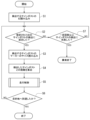
- FIG. 4 is a flow diagram showing the operation of the autonomous mobile robot 1 in one embodiment of the present invention.
- FIG. 5 is a diagram showing an operation table of the autonomous mobile robot 1 in one embodiment of the present invention.
- FIG. 6 is an image diagram showing image data 100 captured by the autonomous mobile robot 1 shown in FIG. First, the operation table of the autonomous mobile robot 1 will be explained. As shown in FIG. 5, the operation table stores STEP input sequences in which the autonomous mobile robot 1 performs predetermined operations in the order of preset operation numbers.
- the user can edit the operation table using the GUI software shown in FIG. 5 (for example, by selecting parameters for each item from the pull-down menu).
- the operation table is stored in each of the autonomous mobile robot 1 and the host system.
- the number string at the left end of the action table shown in FIG. 5 is the action number string. That is, the numbers 0, 1, 2, . . . are operation numbers.
- Each of the items “action”, “parameter”, and “label” is linked to the action number.
- the “Parameter” items include, from the left side, “Sign post size or movement,” “Sign post number or rotation angle,” “Following direction,” “Sign post left/right distance,” and “Sign post longitudinal distance.” is included. The contents of each parameter of the item will be described later together with the operation of the autonomous mobile robot 1.
- the autonomous mobile robot 1 executes operations in the order of the operation numbers in the operation table shown in FIG. 5 (in ascending order of the operation numbers), and reads the identification information of the sign post SP to be detected (step S1).
- the autonomous mobile robot 1 acquires the designated identification information (sign post No. "1" with the operation number "1” shown in FIG. 5) from the image data 100 (see FIG. 6) captured by the imaging unit 26. Detects the sign post SP1 having the following (step S2). Note that detection of the sign post SP is performed for each frame (one piece) of the image data 100 captured by the imaging unit 26.
- step S7 determines whether or not it has failed to detect the sign post SP1 a certain number of times or more. If step S7 is YES, the autonomous mobile robot 1 determines that an abnormality such as a failure of the imaging unit 26 or the disappearance of the sign post SP has occurred, and ends the operation.
- step S2 the autonomous mobile robot 1 determines the size of the marker (first sign) of the actual sign post SP1 (as shown in FIG. 5) from the identification information of the sign post SP1.
- the sign post size "L" of the operation number "1" is read (step S3).
- the autonomous mobile robot 1 signs the sign based on the size of the marker (first sign) of the sign post SP1 on the image data 100 and the read size of the marker (first sign) of the actual sign post SP1.
- a distance D1 to the post SP1 is calculated (step S4).
- the autonomous mobile robot 1 performs travel control of operation number "1" shown in FIG. 5 (step S5).
- the travel control set to the operation number "1” the “following direction” is “right”
- the “sign post left/right distance” is “0.5”
- the “sign post longitudinal distance” is “1”.
- the traveling control set to the operation number “1” is the “following direction” where "right” is selected (set)
- the “sign post left/right direction” where "0.5” is selected (set) This is executed based on the "distance” and the “distance before and after the sign post” for which "1” is selected (set).
- the autonomous mobile robot 1 advances ( follow).
- the autonomous mobile robot 1 approaches the sign post SP1 to a distance of 1 meter, it concludes (determines) that it has reached the destination of the motion number "1", finishes the motion of the motion number "1", and moves on to the next one. Execute the operation with operation number "2". Based on the motion with motion number "2", the guidance target (the target for guiding the autonomous mobile robot 1) is switched to the next sign post SP2.
- the operation of operation number "2" is also similar to the operation of operation number "1" described above.
- the autonomous mobile robot 1 reads the identification information of the sign post SP2 to be detected next (step S1).
- the autonomous mobile robot 1 acquires designated identification information (sign post No. "2" with operation number "2” shown in FIG. 5) from the image data 100 (see FIG. 6) captured by the imaging unit 26.
- a sign post SP2 having a sign post SP2 is detected (step S2).
- step S2 the autonomous mobile robot 1 determines the size of the marker (second sign) of the actual sign post SP2 (as shown in FIG. 5) from the identification information of the sign post SP2.
- the autonomous mobile robot 1 signs the sign based on the size of the marker (second sign) of the sign post SP2 on the image data 100 and the read size of the marker (second sign) of the actual sign post SP2.
- a distance D1 to the post SP2 is calculated (step S4).
- the autonomous mobile robot 1 performs travel control of operation number "2" (step S5).
- the travel control set to operation number "2” the “following direction” is “front”, the “sign post left/right distance” is “0”, and the “sign post longitudinal distance” is “1”.
- the traveling control set to operation number “2” is "Following direction” where “Front” is selected (set) and “Sign post left/right distance” where "0” is selected (set). and “distance before and after sign post” for which "1” is selected (set).
- the autonomous mobile robot 1 advances (follows) toward the "front” of the sign post SP2 with a left-right distance of "0" meters.
- step S6 the autonomous mobile robot 1 performs the action with the action number "2". Then, the next operation with operation number "3" is executed.
- the “action” set to action number "3" is “rotation”.
- the “motion” parameter of this rotation is “clockwise rotation” and the “rotation angle” parameter is "90" degrees. That is, as shown in FIG. 1, the autonomous mobile robot 1 rotates 90 degrees to the right in front of the sign post SP2. In this way, the autonomous mobile robot 1 executes operations in the order of the operation numbers in the operation table shown in FIG. 5, and moves from a predetermined start point to a predetermined goal point.
- the autonomous mobile robot 1 detects the sign post SP placed along the movement route 10 with the mounted imaging unit 26, and moves guided by the sign post SP.
- the movement route 10 of the autonomous mobile robot 1 is specified by setting the relative position to the sign post SP, and by installing a plurality of sign posts SP along the route, a long-distance route can be created. Further, by sequentially switching the sign posts SP detected while the autonomous mobile robot 1 is moving along the route, the autonomous mobile robot 1 can continue traveling.
- the autonomous mobile robot 1 may be changed to a smaller size so that the angle of view of the image data captured by the imaging unit (the angle of view of the camera) even if the sign post SP approaches .
- the size of the marker of the sign post SP on the image data is set for each sign post SP detected by the imaging unit 26, and the size of the marker of the sign post SP is linked with the identification information of the sign post SP when setting a route.
- the actual size of the SP marker can also be registered. Then, when calculating the distance between the autonomous mobile robot 1 and the sign post SP, the actual size of the marker of the sign post SP is used.
- the marker (first sign) of the sign post SP1 of a normal size close to the autonomous mobile robot 1 and the marker (first sign) of the sign post SP1 of the autonomous mobile robot 1 are included.
- the marker (second sign) of a large-sized sign post SP2 far away from the sign post SP2 is reflected at the same time, and the markers of the two sign posts SP (SP1, SP2) are displayed in the same size on the image data 100.
- the autonomous mobile robot 1 can accurately calculate the distance to the two sign posts SP (SP1, SP2) and perform guidance control.
- the sign post SP placed along the movement path 10 is detected by the mounted imaging unit 26, and the autonomous mobile robot 1 that moves while being guided by the sign post SP.
- the marker of the sign post SP has a plurality of sizes
- the storage unit 25 stores individual identification information of the sign post SP and the size of the marker of the actual sign post SP corresponding to the identification information.
- a calculation unit 27 that calculates the distance from the sign post SP based on the size of the marker of the SP. According to this configuration, even if the marker of the sign post SP has a plurality of sizes, the distance to the sign post SP can be accurately calculated and the autonomous mobile robot 1 can be guided and controlled.
- the predetermined actions are performed in the order of preset action numbers based on the identification information acquired from the sign post SP.
- the predetermined operations are performed in the order of the operation numbers, so advanced knowledge and complicated effort are not required for setting the operations.
- the autonomous mobile robot 1 of this embodiment when it approaches the sign to a predetermined distance, it switches the guidance target to the next sign having the identification information set to the next operation number and moves.
- a long-distance route can be created by installing a plurality of sign posts SP along the route.
- the marker of the sign post SP is square, and the storage unit 25 stores the size of one side of the marker of the sign post SP as the actual size of the marker of the sign post SP.
- the storage capacity and the amount of calculation processing can be reduced.
- the autonomous mobile robot 1 of this embodiment includes a communication unit that receives identification information and information on the size of the marker of the actual sign post SP corresponding to the identification information from the host system.
- the settings can be completed by editing the operation table shown in FIG. 5 using input from a PC, etc., so that advanced knowledge and complicated labor are not required to change the settings of the travel route 10.
- autonomous mobile robot 1 and the control system for the autonomous mobile robot 1 described above can also be explained as follows. Similar to the autonomous mobile robot 1 and the control system for the autonomous mobile robot 1 described above, the autonomous mobile robot 1 and the control system for the autonomous mobile robot 1 described below can provide the same operational effects as those described above.
- the autonomous mobile robot is an autonomous mobile robot that has multiple sizes, is placed along a movement route, moves guided by a plurality of marks including a first mark and a second mark, and captures image data.
- a storage unit that stores individual identification information of each of the plurality of signs and an individual actual size of each of the plurality of signs corresponding to the individual identification information;
- the first mark is detected from the captured image data, the individual identification information of the first mark is acquired, and the size of the first mark on the image data and the individual identification information of the first mark are determined.
- a calculation unit that calculates a distance to the first marker based on the individual actual size of the first marker corresponding to the identification information.
- the autonomous mobile robot performs predetermined actions in the order of preset action numbers based on the individual identification information acquired from the first marker.
- the autonomous mobile robot When the autonomous mobile robot approaches the first mark to a predetermined distance, it switches the guidance target to the second mark having the individual identification information set to the next operation number and moves.
- the shape of the first mark is a square
- the storage unit stores the size of one side of the first mark as the individual actual size of the first mark.
- the shape of the second mark is a square
- the storage unit stores the size of one side of the second mark as the individual actual size of the second mark.
- the autonomous mobile robot receives, from an external device, the individual identification information of each of the plurality of signs and the information of the individual actual size of each of the plurality of signs corresponding to the individual identification information. It further includes a communication section.
- a control system for an autonomous mobile robot is a control system for an autonomous mobile robot that has a plurality of sizes, is arranged along a movement route, and moves while being guided by a plurality of marks including a first mark and a second mark.
- an imaging unit that captures image data
- a storage unit that stores individual identification information of each of the plurality of signs and an individual actual size of each of the plurality of signs corresponding to the individual identification information.
- detecting the first mark from the image data captured by the imaging unit acquiring the individual identification information of the first mark, and detecting the size of the first mark on the image data and the first mark.
- a calculation unit that calculates a distance from the first marker based on the individual actual size of the first marker corresponding to the individual identification information of the marker.
- the registered (stored) size of the marker of the sign post SP can be set at a ratio that is larger than the normal individual difference in human faces, based on the marker of the normal sign post SP. That is, the size of the marker of the sign post SP registered (stored) in the storage unit 25 is such that the ratio of the small size to the normal size of the markers of the sign post SP is the (normal size) of the marker of the sign post SP to the normal size of the human face. It may be set to be smaller than the small size ratio (within the range of individual differences).
- the size of the marker of the sign post SP registered (stored) in the storage unit 25 is such that the ratio of the large size to the normal size among the markers of the sign post SP is the (normal size) to the normal size of the human face. It may be set to be larger than the ratio of large sizes (within the range of individual differences). For example, if the size of the marker of a normal sign post SP is "L", the size of the marker of the sign post SP registered in the storage unit 25 is 1/2 (0.5L) or less, or twice the size of the marker of a normal sign post SP. (2L) or more, 1/5 times (0.2L) or less, or 5 times (5L) or more, 1/10 times (0.1L) or less, or 10 times (10L) ) or more can be set.
- the autonomous mobile robot 1 may be a flying object, etc. commonly called a drone.
- a configuration in which a plurality of sign posts SP are arranged along the moving route 10 has been described, but a configuration in which only one sign post SP is arranged may be used.
- an autonomous mobile robot and a control system for an autonomous mobile robot that can accurately calculate the distance to the sign and guide and control even if the sign has a plurality of sizes.
Landscapes
- Engineering & Computer Science (AREA)
- Physics & Mathematics (AREA)
- General Physics & Mathematics (AREA)
- Aviation & Aerospace Engineering (AREA)
- Radar, Positioning & Navigation (AREA)
- Remote Sensing (AREA)
- Automation & Control Theory (AREA)
- Theoretical Computer Science (AREA)
- Multimedia (AREA)
- Computer Vision & Pattern Recognition (AREA)
- Control Of Position, Course, Altitude, Or Attitude Of Moving Bodies (AREA)
- Manipulator (AREA)
Priority Applications (5)
| Application Number | Priority Date | Filing Date | Title |
|---|---|---|---|
| JP2024533761A JPWO2024014529A1 (https=) | 2022-07-15 | 2023-07-14 | |
| DE112023003083.9T DE112023003083T5 (de) | 2022-07-15 | 2023-07-14 | Autonomer mobiler Roboter und System zur Steuerung eines autonomen mobilen Roboters |
| US18/994,309 US20260029792A1 (en) | 2022-07-15 | 2023-07-14 | Autonomous mobile robot and system for controlling autonomous mobile robot |
| KR1020257000286A KR20250037748A (ko) | 2022-07-15 | 2023-07-14 | 자율 이동 로봇 및 자율 이동 로봇의 제어 시스템 |
| CN202380052889.5A CN119452324A (zh) | 2022-07-15 | 2023-07-14 | 自主移动机器人以及自主移动机器人的控制系统 |
Applications Claiming Priority (2)
| Application Number | Priority Date | Filing Date | Title |
|---|---|---|---|
| JP2022113975 | 2022-07-15 | ||
| JP2022-113975 | 2022-07-15 |
Publications (1)
| Publication Number | Publication Date |
|---|---|
| WO2024014529A1 true WO2024014529A1 (ja) | 2024-01-18 |
Family
ID=89536865
Family Applications (1)
| Application Number | Title | Priority Date | Filing Date |
|---|---|---|---|
| PCT/JP2023/026015 Ceased WO2024014529A1 (ja) | 2022-07-15 | 2023-07-14 | 自律移動ロボット及び自律移動ロボットの制御システム |
Country Status (7)
| Country | Link |
|---|---|
| US (1) | US20260029792A1 (https=) |
| JP (1) | JPWO2024014529A1 (https=) |
| KR (1) | KR20250037748A (https=) |
| CN (1) | CN119452324A (https=) |
| DE (1) | DE112023003083T5 (https=) |
| TW (1) | TW202420010A (https=) |
| WO (1) | WO2024014529A1 (https=) |
Cited By (1)
| Publication number | Priority date | Publication date | Assignee | Title |
|---|---|---|---|---|
| RU227202U1 (ru) * | 2024-03-13 | 2024-07-11 | Общество С Ограниченной Ответственностью "Беспилотный Погрузчик" | Устройство для ориентирования автономного мобильного робота по видеопотокам в оптическом диапазоне |
Citations (3)
| Publication number | Priority date | Publication date | Assignee | Title |
|---|---|---|---|---|
| JP2015121928A (ja) * | 2013-12-24 | 2015-07-02 | トヨタ自動車株式会社 | 自律移動ロボットの制御方法 |
| WO2019240208A1 (ja) * | 2018-06-13 | 2019-12-19 | Groove X株式会社 | ロボットおよびその制御方法、ならびにプログラム |
| WO2021261480A1 (ja) * | 2020-06-23 | 2021-12-30 | Thk株式会社 | 自律移動ロボット連係システム及び自律移動ロボット |
Family Cites Families (3)
| Publication number | Priority date | Publication date | Assignee | Title |
|---|---|---|---|---|
| US10217363B2 (en) * | 2015-10-29 | 2019-02-26 | Faraday&Future Inc. | Methods and systems for electronically assisted lane entrance |
| JP7065383B2 (ja) * | 2017-06-30 | 2022-05-12 | パナソニックIpマネジメント株式会社 | 表示システム、情報提示システム、表示システムの制御方法、プログラム、及び移動体 |
| US12594954B2 (en) * | 2021-05-28 | 2026-04-07 | Nvidia Corporation | Perception-based sign detection and interpretation for autonomous machine systems and applications |
-
2023
- 2023-07-14 DE DE112023003083.9T patent/DE112023003083T5/de active Pending
- 2023-07-14 US US18/994,309 patent/US20260029792A1/en active Pending
- 2023-07-14 TW TW112126308A patent/TW202420010A/zh unknown
- 2023-07-14 JP JP2024533761A patent/JPWO2024014529A1/ja active Pending
- 2023-07-14 KR KR1020257000286A patent/KR20250037748A/ko active Pending
- 2023-07-14 CN CN202380052889.5A patent/CN119452324A/zh active Pending
- 2023-07-14 WO PCT/JP2023/026015 patent/WO2024014529A1/ja not_active Ceased
Patent Citations (3)
| Publication number | Priority date | Publication date | Assignee | Title |
|---|---|---|---|---|
| JP2015121928A (ja) * | 2013-12-24 | 2015-07-02 | トヨタ自動車株式会社 | 自律移動ロボットの制御方法 |
| WO2019240208A1 (ja) * | 2018-06-13 | 2019-12-19 | Groove X株式会社 | ロボットおよびその制御方法、ならびにプログラム |
| WO2021261480A1 (ja) * | 2020-06-23 | 2021-12-30 | Thk株式会社 | 自律移動ロボット連係システム及び自律移動ロボット |
Cited By (2)
| Publication number | Priority date | Publication date | Assignee | Title |
|---|---|---|---|---|
| RU227202U1 (ru) * | 2024-03-13 | 2024-07-11 | Общество С Ограниченной Ответственностью "Беспилотный Погрузчик" | Устройство для ориентирования автономного мобильного робота по видеопотокам в оптическом диапазоне |
| RU2825022C1 (ru) * | 2024-04-05 | 2024-08-19 | Общество С Ограниченной Ответственностью "Беспилотный Погрузчик" | Программно-аппаратный комплекс для управления автономным мобильным роботом-погрузчиком |
Also Published As
| Publication number | Publication date |
|---|---|
| DE112023003083T5 (de) | 2025-10-02 |
| KR20250037748A (ko) | 2025-03-18 |
| TW202420010A (zh) | 2024-05-16 |
| US20260029792A1 (en) | 2026-01-29 |
| CN119452324A (zh) | 2025-02-14 |
| JPWO2024014529A1 (https=) | 2024-01-18 |
Similar Documents
| Publication | Publication Date | Title |
|---|---|---|
| KR102502219B1 (ko) | 로봇 운동시 카펫으로 인한 드리프트 제어방법, 칩 및 청소 로봇 | |
| US9244463B2 (en) | Automated guided vehicle and method of operating an automated guided vehicle | |
| JP7627795B2 (ja) | 移動ロボット用制御装置、移動ロボットの制御方法 | |
| EP3674830B1 (en) | Server and method for controlling laser irradiation of movement path of robot, and robot that moves based thereon | |
| TWI806933B (zh) | 移動機器人之控制系統、移動機器人之控制方法 | |
| CN108780317B (zh) | 自动搬运车 | |
| CN109478066B (zh) | 移动机器人以及控制方法 | |
| JP2012084149A (ja) | モバイル機器のナビゲーション | |
| CN111089595B (zh) | 一种机器人的检测数据融合方法和主控芯片及机器人 | |
| US20210150750A1 (en) | Moving body and system | |
| WO2024014529A1 (ja) | 自律移動ロボット及び自律移動ロボットの制御システム | |
| WO2019069921A1 (ja) | 移動体 | |
| EP1209902B1 (en) | Image pick-up method and image pick-up system | |
| Jensfelt et al. | A mobile robot system for automatic floor marking | |
| CA2957380A1 (en) | Vision-based system for navigating a robot through an indoor space | |
| JP7045829B2 (ja) | 移動ロボットの制御システム、移動ロボットの制御方法 | |
| KR100703882B1 (ko) | 단일 카메라 기반 포즈인식이 가능한 이동로봇 및 그 방법 | |
| WO2025192084A1 (ja) | 搬送システム、管理装置、及び搬送システムの管理方法 | |
| JP2026056736A (ja) | センシングユニット及び自律移動ロボット | |
| JP2023074154A (ja) | 自律移動ロボット | |
| WO2024135667A1 (ja) | 自律移動ロボット | |
| Rembold et al. | An integrated sensor system for robots | |
| JP2022147855A (ja) | 自動走行装置 |
Legal Events
| Date | Code | Title | Description |
|---|---|---|---|
| WWE | Wipo information: entry into national phase |
Ref document number: 2024533761 Country of ref document: JP |
|
| WWE | Wipo information: entry into national phase |
Ref document number: 202380052889.5 Country of ref document: CN |
|
| WWE | Wipo information: entry into national phase |
Ref document number: 18994309 Country of ref document: US |
|
| WWP | Wipo information: published in national office |
Ref document number: 202380052889.5 Country of ref document: CN |
|
| WWE | Wipo information: entry into national phase |
Ref document number: 112023003083 Country of ref document: DE |
|
| WWP | Wipo information: published in national office |
Ref document number: 1020257000286 Country of ref document: KR |
|
| 122 | Ep: pct application non-entry in european phase |
Ref document number: 23839698 Country of ref document: EP Kind code of ref document: A1 |
|
| WWP | Wipo information: published in national office |
Ref document number: 112023003083 Country of ref document: DE |
|
| WWP | Wipo information: published in national office |
Ref document number: 18994309 Country of ref document: US |