WO2024014243A1 - 車載装置、プログラム及び情報処理方法 - Google Patents
車載装置、プログラム及び情報処理方法 Download PDFInfo
- Publication number
- WO2024014243A1 WO2024014243A1 PCT/JP2023/022946 JP2023022946W WO2024014243A1 WO 2024014243 A1 WO2024014243 A1 WO 2024014243A1 JP 2023022946 W JP2023022946 W JP 2023022946W WO 2024014243 A1 WO2024014243 A1 WO 2024014243A1
- Authority
- WO
- WIPO (PCT)
- Prior art keywords
- clock signal
- clock
- processing unit
- clock oscillator
- correction
- Prior art date
- Legal status (The legal status is an assumption and is not a legal conclusion. Google has not performed a legal analysis and makes no representation as to the accuracy of the status listed.)
- Ceased
Links
Images




Classifications
-
- B—PERFORMING OPERATIONS; TRANSPORTING
- B60—VEHICLES IN GENERAL
- B60R—VEHICLES, VEHICLE FITTINGS, OR VEHICLE PARTS, NOT OTHERWISE PROVIDED FOR
- B60R16/00—Electric or fluid circuits specially adapted for vehicles and not otherwise provided for; Arrangement of elements of electric or fluid circuits specially adapted for vehicles and not otherwise provided for
- B60R16/02—Electric or fluid circuits specially adapted for vehicles and not otherwise provided for; Arrangement of elements of electric or fluid circuits specially adapted for vehicles and not otherwise provided for electric constitutive elements
-
- G—PHYSICS
- G06—COMPUTING OR CALCULATING; COUNTING
- G06F—ELECTRIC DIGITAL DATA PROCESSING
- G06F1/00—Details not covered by groups G06F3/00 - G06F13/00 and G06F21/00
- G06F1/04—Generating or distributing clock signals or signals derived directly therefrom
Definitions
- the present disclosure relates to an in-vehicle device, a program, and an information processing method.
- This application claims priority based on Japanese Application No. 2022-111266 filed on July 11, 2022, and incorporates all the contents described in the said Japanese application.
- the wiper drive device of Patent Document 1 includes a vehicle-mounted ECU (body ECU) and is driven by a control program applied to the vehicle-mounted ECU.
- An in-vehicle device is an in-vehicle device that is mounted on a vehicle, and includes a first clock oscillator, a second clock oscillator with a lower speed and lower accuracy than the first clock oscillator, and a second clock oscillator with lower speed and accuracy than the first clock oscillator.
- a processing unit incorporating a two-clock oscillator; the processing unit obtains a first clock signal from the first clock oscillator, obtains a second clock signal from the second clock oscillator, and A correction value is derived based on the clock signal and the second clock signal, and processing related to correction of the second clock signal is performed using the derived correction value.
- FIG. 1 is a schematic diagram showing the configuration of an in-vehicle system including an in-vehicle device according to a first embodiment.
- FIG. 2 is a block diagram showing the configuration of an on-vehicle device.
- FIG. 7 is an explanatory diagram showing an example of the operation of a first clock oscillator and a second clock oscillator in correction processing.
- FIG. 3 is an explanatory diagram showing an example of a functional unit related to correction processing.
- FIG. 6 is an explanatory diagram illustrating an example of aggregation processing of differences (errors) performed multiple times.
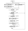
- 3 is a flowchart illustrating processing of a processing unit of an on-vehicle device.
- FIG. 7 is a flowchart illustrating processing of a processing unit of an in-vehicle device according to a second embodiment (wake-up).
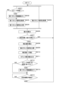
- 12 is a flowchart illustrating processing of a processing unit of an in-vehicle device according to Embodiment 3 (temperature difference).
- 12 is a flowchart illustrating the processing of the processing unit of the in-vehicle device according to the fourth embodiment (temporal change rate).
- An object of the present disclosure is to provide an in-vehicle device and the like that can efficiently improve the accuracy of a clock oscillator.
- An in-vehicle device is an in-vehicle device installed in a vehicle, which includes a first clock oscillator and a second clock oscillator having a lower speed and lower accuracy than the first clock oscillator. , a processing unit incorporating the second clock oscillator, the processing unit acquiring a first clock signal from the first clock oscillator, and acquiring a second clock signal from the second clock oscillator. A correction value is derived based on the first clock signal and the second clock signal, and processing related to correction of the second clock signal is performed using the derived correction value.
- the processing unit included in the on-vehicle device is configured by, for example, a microcomputer.
- the in-vehicle device includes two clock oscillators, a first clock oscillator and a second clock oscillator, and the second clock oscillator is of a type built in a processing unit (microcomputer).
- the first clock oscillator (external clock) is configured to be externally attached to the processing unit (microcomputer), and is faster than the second clock oscillator (internal clock) built into the processing unit (microcomputer). High speed and high precision.
- the first clock oscillator corresponds to a high-speed, high-precision clock
- the second clock oscillator corresponds to a low-speed, low-precision clock.
- the processing unit derives a correction value for the second clock signal based on the first clock signal obtained from the first clock oscillator and the second clock signal obtained from the second clock oscillator, using the first clock signal as a reference. do. Since the processing section performs processing related to correction of the second clock signal using the derived correction value, it is possible to substantially improve the accuracy of the second clock oscillator built in the processing section.
- the second clock oscillator can correct the second clock signal output from the second clock oscillator and use the corrected second clock signal.
- the actual accuracy (practical accuracy) can be improved.
- the process related to correction of the second clock signal may include, for example, a process using a timer counter function or a process using a clock trimming function.
- the timer counter function By using the timer counter function, the value obtained by correcting the second clock signal using the correction value (corrected clock signal) can be reflected in the timer count of the timer unit that performs the timekeeping function.
- the speed of the second clock oscillator may be corrected by using a clock trimming function.
- the processing unit calculates a first measurement time calculated by frequency-dividing the first clock signal and a second measurement time calculated based on the second clock signal.
- the correction value is derived based on the difference between
- the processing unit of the in-vehicle device divides the frequency of the first clock signal output from the first clock oscillator in accordance with the frequency of the second clock signal output from the second clock oscillator.
- the frequencies of the divided first clock signal and the second clock oscillator are thereby matched. For example, if the frequency of the first clock signal is 32 MHz and the frequency of the second clock signal is 32 KHz, the frequency of the first clock signal can be divided by reducing the frequency to 1/1000 and converting it. There may be. Then, based on a predetermined measurement unit time, calculate the difference between the first measurement time calculated using the frequency-divided first clock signal and the second measurement time calculated using the second clock signal, and Based on this, a correction value is derived.
- the difference (difference value) obtained by subtracting the second measurement time by the second clock oscillator from the first measurement time by the first clock oscillator is a positive value
- the clock generation by the second clock oscillator is delayed. It is determined that In this case, the correction value will be a positive value.
- the speed of the second clock oscillator may be increased.
- the difference (difference value) obtained by subtracting the second measurement time by the second clock oscillator from the first measurement time by the first clock oscillator is a negative value
- the clock generation by the second clock oscillator is progressing. It is determined that In this case, the correction value will be a negative value.
- the speed of the second clock oscillator may be reduced. With such a configuration, it is possible to efficiently perform processing related to correction of the second clock signal according to the difference between the first measurement time by the first clock oscillator and the second measurement time by the second clock oscillator. I can do it.
- the processing unit calculates a plurality of differences by acquiring the first clock signal and the second clock signal a plurality of times, and Based on this, the correction value is derived.
- the processing unit of the in-vehicle device repeats the process of acquiring the first clock signal and the second clock signal in parallel multiple times, for example, 30 times, at the same timing (at the time of acquisition). For example, the processing unit of the in-vehicle device acquires the second clock signal of multiple cycles from the high-speed first clock oscillator in accordance with the time of one cycle from the low-speed second clock oscillator, and outputs the second clock signal from the first clock oscillator.
- a difference calculation process is performed to calculate the difference between the first measurement time calculated by dividing the frequency of the clock signal and the second measurement time calculated using the second clock signal.
- the processing unit of the in-vehicle device obtains the first clock signal and the second clock signal multiple times, and stores the difference (difference value) calculated each time in the storage unit, thereby performing the difference calculation process multiple times. conduct.
- the processing unit of the in-vehicle device performs aggregation processing by averaging these plurality of differences (difference values), for example, and derives a correction value using the average value. In this way, by using a plurality of differences calculated by acquiring the first clock signal and the second clock signal multiple times, it is possible to take measures even when there is a shift (jitter) between the clocks. The accuracy of correction to the second clock signal can be improved.
- the processing unit performs processing related to correction of the second clock signal when the vehicle is started.
- the processing unit of the in-vehicle device performs processing related to correction of the second clock signal, for example, when the IG switch is turned on and the vehicle is started. Therefore, when the vehicle is started, the on-vehicle device is also started, and as part of the start-up process of the on-vehicle device, it is possible to deal with initial variations (center shift) in the first clock oscillator and the second clock oscillator. As a result, even if there is initial variation (center shift) between the first clock oscillator and the second clock oscillator when the in-vehicle device starts up, it is possible to take countermeasures against this, and to correct the second clock signal. Accuracy can be improved.
- the processing unit performs processing related to correction of the second clock signal at a predetermined cycle.
- the processing unit of the in-vehicle device performs processing related to correction of the second clock signal at a predetermined period, such as every 10 minutes, while the vehicle is starting up.
- a predetermined period such as every 10 minutes
- periodic correction can be made for temporal fluctuations in the ambient temperature (atmosphere temperature) of the on-vehicle device. , it is possible to improve the accuracy of correction to the second clock signal.
- the second clock oscillator maintains an active state even when the first clock oscillator is inactive, and the processing unit When the oscillator is inactive, the first clock oscillator is transitioned to the active state, and then processing related to correction of the second clock signal is performed.
- the in-vehicle device when the in-vehicle device receives a sleep signal, it transitions to an inactive state (sleep state) by leaving only some functions such as the communication system and stopping other functions, and consumes Power saving control is performed to reduce power (dark current).
- the power supply to the first clock oscillator is also stopped and the first clock oscillator is turned off, thereby transitioning to the inactive state.
- the second clock oscillator is configured to maintain an active state (on) even when the vehicle-mounted device is in an inactive state (off).
- the second clock oscillator may be maintained in an active state (on) by being constantly supplied with power, for example, from a power supply device mounted on the vehicle.
- the second clock oscillator is configured such that while the vehicle is activated (IG on), power is continued to be supplied from the power supply device mounted on the vehicle even if the on-vehicle device receives a sleep signal. It may be something that In this way, the second clock oscillator always remains active (on) regardless of whether it receives a sleep signal or the like, so it will remain active (on) regardless of whether it receives a sleep signal or the like. It can be used as a measuring means for measuring time.
- the period in which the first clock oscillator is on and the period in which the second clock oscillator is on are different, that is, the integration of the first clock oscillator
- the on period is shorter than the cumulative on period of the second clock oscillator.
- the processing unit of the in-vehicle device transitions the first clock oscillator to an active state (on), and then performs processing related to correction of the second clock signal. Therefore, processing related to correction of the second clock signal can be performed regardless of the state of the first clock oscillator.
- the processing unit acquires temperature data that affects the operation of the second clock oscillator, and according to a change state of the acquired temperature data, the processing unit 2. Performs processing related to correction of the clock signal.
- the processing unit of the in-vehicle device periodically acquires temperature data from a temperature sensor connected to or built into the in-vehicle device (processing unit), and stores it in the storage unit.
- the temperature sensed by the temperature sensor is the ambient temperature (ambient temperature) or internal temperature of the processing section, and corresponds to the temperature that affects the operation of the second clock oscillator.
- the oscillation characteristics (oscillator characteristics) of the second clock oscillator include temperature characteristics that are affected by the surrounding temperature or atmospheric temperature of the second clock oscillator, and the oscillation period (operation characteristic) changes depending on the increase or decrease in temperature (time fluctuation of temperature). There is a concern that this may affect the accuracy of the second clock signal output from the second clock oscillator.
- the processing unit of the in-vehicle device performs processing related to correction of the second clock signal in response to cases such as when the state of change in temperature data that affects the operation of the second clock oscillator exceeds a predetermined threshold. .
- the processing unit of the in-vehicle device performs processing related to correction of the second clock signal in response to cases such as when the state of change in temperature data that affects the operation of the second clock oscillator exceeds a predetermined threshold.
- the state of change of the temperature data includes temperature data at the time of processing regarding the correction of the second clock signal performed immediately before, and temperature data at the time of acquisition after the time of processing. including a state due to a temperature difference between the temperature data, and when the absolute value of the temperature difference between the two temperature data is equal to or greater than a predetermined temperature difference threshold, the processing unit performs processing related to correction of the second clock signal. conduct.
- the processing unit of the in-vehicle device acquires temperature data regularly or periodically output from the temperature sensor, and stores the temperature data in the storage unit as temperature change history data associated with the acquisition time. ing.
- the processing unit of the in-vehicle device generates temperature data corresponding to the processing time point related to the correction of the second clock signal performed immediately before (temperature data at the acquisition time point closest to the processing time point: T1) and the acquisition time point after the processing time point.
- the difference (temperature difference) between the two temperature data (T2) is calculated.
- Ts predetermined temperature difference threshold
- the processing unit performs processing related to correction of the second clock signal.
- processing related to correction of the second clock signal can be appropriately performed in response to temperature conversion that affects the operation of the second clock oscillator.
- the change state of the temperature data includes a state according to a time change rate of two temperature data at different acquisition times, and the processing unit If the time rate of change is equal to or greater than a predetermined rate of change threshold, a process related to correction of the second clock signal is performed.
- the processing unit of the in-vehicle device acquires temperature data regularly or periodically output from the temperature sensor, and stores the temperature data in the storage unit as temperature change history data associated with the acquisition time. ing.
- the processing unit of the in-vehicle device calculates the time rate of change (
- the processing unit of the in-vehicle device performs processing related to correction of the second clock signal. Thereby, processing related to correction of the second clock signal can be appropriately performed in response to temperature conversion that affects the operation of the second clock oscillator.
- the processing unit outputs the second clock signal corrected by the correction value to a time measurement unit that measures the elapsed time from the start of the vehicle. do.
- the processing unit of the in-vehicle device generates a second clock signal (corrected clock signal) that has been processed using the correction value, that is, a corrected clock that conforms to the accuracy of the first clock oscillator that functions as a high-speed, high-precision clock.
- the signal is output to a timer such as a global timer that measures the time elapsed since the vehicle was started.
- the timekeeping unit global timer
- An information processing method includes a computer that includes a second clock oscillator that is communicably connected to a first clock oscillator and has a lower speed and lower accuracy than the first clock oscillator.
- a first clock signal is obtained from a first clock oscillator
- a second clock signal is obtained from the second clock oscillator
- a correction value is derived based on the obtained first clock signal and second clock signal.
- a process for correcting the second clock signal is executed using the corrected correction value.
- a program is configured to cause a computer to include a second clock oscillator that is communicably connected to a first clock oscillator and has a lower speed and lower accuracy than the first clock oscillator.
- a first clock signal is obtained from the clock oscillator
- a second clock signal is obtained from the second clock oscillator
- a correction value is derived based on the obtained first clock signal and the second clock signal
- the derived correction value is A process for correcting the second clock signal is executed using the correction value.
- FIG. 1 is a schematic diagram showing the configuration of an in-vehicle system including an in-vehicle device 1 according to a first embodiment.
- FIG. 2 is a block diagram showing the configuration of the in-vehicle device 1.
- the in-vehicle system is configured with an in-vehicle device 1 as a main device, and includes an in-vehicle network 3 configured with, for example, a CAN (Control Area Network) bus or an Ethernet (registered trademark) cable.
- CAN Control Area Network
- Ethernet registered trademark
- a plurality of in-vehicle ECUs 2 are connected to the in-vehicle network 3, and the in-vehicle device 1 is communicably connected to these in-vehicle ECUs 2.
- the in-vehicle device 1 is further connected via a power line to a power supply device 4 configured with a secondary battery such as a lead battery, an alternator, or a lithium ion battery, and is supplied with power from the power supply device 4 .
- the in-vehicle device 1 includes a processing section 10 configured by, for example, a microcomputer, and a first clock oscillator 15 externally attached to the processing section 10.
- the in-vehicle device 1 may be an integrated ECU configured with a central control device such as a vehicle computer.
- the in-vehicle device 1 may be an individual ECU connected under an integrated ECU and connected to a plurality of actuators, sensors, or the like.
- the in-vehicle device 1 may be a body ECU that controls body actuators such as wipers or door mirrors.
- the processing unit 10 is composed of a microcomputer or the like, and includes a control unit 11, a storage unit 12, a communication unit 13, an input/output I/F 14, a second clock oscillator 16, and a timer 17.
- the control unit 11 is composed of a CPU (Central Processing Unit), an MPU (Micro Processing Unit), etc., and reads out and executes a program P (program product) and data stored in advance in the storage unit 12 to perform various operations. The control processing and arithmetic processing are performed.
- the storage unit 12 is a volatile memory element such as RAM (Random Access Memory), a non-volatile memory element such as ROM (Read Only Memory), EEPROM (Electrically Erasable Programmable ROM), or flash memory, or these storage devices.
- a program P (program product) and data to be referred to during processing are stored in advance.
- the program P (program product) stored in the storage unit 12 may be a program P (program product) read from a recording medium M readable by the in-vehicle device 1.
- the program P (program product) may be downloaded from an external computer (not shown) connected to a communication network (not shown) and stored in the storage unit 12.
- the communication unit 13 is a communication interface using, for example, a CAN (Control Area Network) or Ethernet (registered trademark) communication protocol, and the control unit 11 is connected to the in-vehicle network 3 via the communication unit 13. Communicate with other in-vehicle ECUs 2.
- a message indicating the on or off state is transmitted from the in-vehicle ECU 2, and the control unit 11 obtains the message via the communication unit 13. You can.
- the input/output I/F 14 is, for example, a communication interface for serial communication.
- a temperature sensor 141 composed of, for example, a thermistor is connected to the input/output I/F 14 .
- the temperature sensor 141 connected in this manner is built into the processing unit 10 and outputs sensored temperature data to the control unit 11 periodically or regularly.
- the temperature data output by the temperature sensor 141 is, for example, the ambient temperature (ambient temperature) or internal temperature of the processing unit 10, and corresponds to the temperature that affects the operation of the second clock oscillator 16.
- the second clock oscillator 16 is a low-speed, low-precision (for example, 32 KHz: error ⁇ 10%) clock oscillator that is configured with, for example, a CR oscillation circuit.
- the second clock oscillator 16 is a built-in clock oscillator built into the microcomputer that constitutes the processing section 10 .
- the second clock oscillator 16 is configured to be always on (active state) regardless of whether the vehicle-mounted device 1 is in a sleep state (inactive state) or not.
- the timer unit 17 is, for example, a timer (global timer) that measures the elapsed time since the vehicle C was started or the elapsed time since the power supply device 4 (battery, etc.) was connected. Although details will be described later, by using the second clock signal from the second clock oscillator 16 that has been corrected according to the oscillation accuracy of the first clock oscillator 15, the timer 17 can achieve the measurement accuracy required by the product specifications. can be guaranteed.
- a timer global timer
- the first clock oscillator 15 is a high-speed, high-precision (for example, 32 MHz: error: 100 ppm) clock oscillator that is configured with a crystal oscillator, for example.
- the first clock oscillator 15 is an external clock oscillator that is externally attached to the microcomputer that constitutes the processing section 10 .
- the first clock oscillator 15 is configured to turn off (inactive) when the vehicle-mounted device 1 enters a sleep state (inactive).
- FIG. 3 is an explanatory diagram showing an example of the operation of the first clock oscillator 15 and the second clock oscillator 16 in the correction process. The operations of the first clock oscillator 15 and the second clock oscillator 16 over time will be described with reference to the illustrations of this embodiment, starting from the time when the in-vehicle device 1 is activated.
- the processing unit 10 of the in-vehicle device 1 starts the startup process when the IG switch is turned on and the vehicle C is started.
- the processing unit 10 of the in-vehicle device 1 executes a correction process for the second clock oscillator 16 as part of the startup process of the in-vehicle device 1.
- the correction process performed as part of the startup process of the in-vehicle device 1 corresponds to the initial correction process.
- the processing unit 10 of the in-vehicle device 1 executes the correction process for the second clock oscillator 16 again after a predetermined period (periodic correction period) stored in advance in the storage unit 12 has elapsed. do. In performing these correction processes, the processing unit 10 of the in-vehicle device 1 acquires the first clock signal output from the first clock oscillator 15 and the second clock signal output from the second lock oscillator.
- the processing unit 10 of the in-vehicle device 1 divides the frequency of the plurality of first clock signals acquired from the first clock oscillator 15 to match the frequency of the second clock signal output from the second lock oscillator. Good too.
- time difference first measurement time - second measurement time
- 2 measurement time 2 measurement time
- the processing unit 10 derives the correction value by executing the process of calculating the difference (difference calculation process) multiple times and using the average difference value obtained by aggregating and averaging the multiple differences. There may be.
- the difference (time difference) corresponds to the error of the second clock oscillator 16 (low speed, low precision clock) with respect to the first clock oscillator 15 (high speed, high precision clock).
- the difference (time difference) corresponding to the error of the second clock oscillator 16 is calculated by subtracting the second measurement time from the first measurement time, the difference (time difference) becomes a positive value. In this case, it means that the second clock oscillator 16 (low-speed, low-precision clock) is delayed. Further, when the difference (time difference) is a negative value, it means that the second clock oscillator 16 (low-speed, low-precision clock) is leading.
- the processing unit 10 of the vehicle-mounted device 1 performs correction processing on the second clock oscillator 16 depending on whether the speed (oscillation cycle) of the second clock oscillator 16 is advanced or delayed.
- the processing unit 10 of the in-vehicle device 1 corrects the second clock signal from the second clock oscillator 16 using the derived correction value, and outputs the corrected second clock signal (corrected clock signal) to the timer unit 17. .
- the processing unit 10 of the in-vehicle device 1 generates a count correction value by applying a correction value to the count value generated using the second clock signal by utilizing the timer count function.
- the count correction value may be reflected in the clock section 17.
- the processing unit 10 of the in-vehicle device 1 may correct the speed (oscillation cycle) of the second clock oscillator 16 by utilizing a clock trimming function.
- the processing unit 10 calculates the speed (oscillation period) of the second clock oscillator 16 if the difference (time difference) is a positive value. ) is made faster, and if the difference (time difference) becomes a negative value, the speed (oscillation cycle) of the second clock oscillator 16 is made slower.
- the periodic correction period is set to about 10 minutes, for example, and is stored in a storage area that is accessible by the processing unit 10, such as the storage unit 12 of the in-vehicle device 1.
- the processing unit 10 of the in-vehicle device 1 can obtain the regular correction period by referring to the storage unit 12.
- the frequency (period) of periodic correction increases or decreases depending on the value of the periodic correction period.
- the frequency (period) of the periodic correction is a trade-off between the correction accuracy and the dark current generated by the in-vehicle device 1, especially the first clock oscillator 15. In other words, as the frequency of periodic correction increases, the power consumption due to the dark current increases. will also increase.
- the periodic correction period is determined from the viewpoint of ensuring the clock accuracy of the second clock oscillator 16 within the required accuracy based on the assumed maximum value of the temperature change in the atmosphere of the in-vehicle device 1 in a unit time such as one hour, for example. It may also be something that does.
- the processing unit 10 of the vehicle-mounted device 1 executes the current correction process when a regular correction period has elapsed since the last correction process. Thereby, the processing unit 10 of the in-vehicle device 1 repeats and executes the periodic correction process at a predetermined period determined by the periodic correction period.
- the clock section 17 executes counting processing using the second clock signal output from the second clock oscillator 16, but by periodically inserting correction processing for the second clock oscillator 16, Accuracy can be achieved.
- the in-vehicle device 1 is configured to reduce power consumption by transitioning to a sleep state (inactive state) when receiving a sleep signal from another in-vehicle ECU 2 such as an integrated ECU via the in-vehicle network 3. has been done.
- a sleep state inactive state
- the first clock oscillator 15 enters an off state (inactive state) by, for example, stopping power supply. That is, the first clock oscillator 15 is turned on (activated state) when the vehicle-mounted device 1 is in a normal startup state (run state) or in a woken-up state.
- the second clock oscillator 16 continues to be supplied with power even when the in-vehicle device 1 is in the sleep state (inactive state), and maintains the on state (active state). .
- the second clock oscillator 16 is configured to always maintain an on state (activated state) regardless of whether or not the vehicle-mounted device 1 is in a sleep state (inactive state).
- the processing unit 10 of the in-vehicle device 1 performs periodic correction when the periodic correction period has elapsed since the last correction process. Execute processing. At this time, the processing unit 10 of the in-vehicle device 1 wakes up the in-vehicle device 1 (self-device) as a pre-processing for the periodic correction process, and changes it from the sleep state (inactive state) to the wake-up state (activated state). It may also be possible to perform periodic wake-up processing that causes the transition to occur.
- the dark current increases by turning off the first clock oscillator 15, which is a high-speed, high-precision clock and therefore consumes a relatively large amount of power, depending on the sleep state of the in-vehicle device 1. It is possible to execute periodic correction processing for the second clock oscillator 16 while suppressing the occurrence of errors.
- the second clock signal subjected to the periodic correction processing to the timekeeping section 17, the accuracy of time measurement by the timekeeping section 17 can be improved and the product accuracy required for the in-vehicle device 1 can be ensured. can.
- FIG. 4 is an explanatory diagram showing an example of a functional unit related to correction processing.
- the control unit 11 included in the processing unit 10 of the in-vehicle device 1 executes the program stored in the storage unit 12 to control the first frequency division unit 111, the correction value derivation unit 112, the second frequency division unit 113, It also functions as a correction clock generation section 114. Processing by these functional units will be explained using illustrations in this embodiment.
- the first frequency divider 111 divides the frequency of the first clock signal obtained from the first clock oscillator 15 (high-speed, high-precision clock).
- the first clock signal from the first clock oscillator 15 is regularly used in various control processing or communication processing by the processing unit 10 of the on-vehicle device 1, and is also regularly input to the first frequency dividing unit 111. be done.
- the first frequency divider 111 may divide the first clock signal in accordance with the frequency of the second clock signal output from the second clock oscillator 16 (low-speed, low-precision clock). For example, if the frequency of the first clock signal oscillated by the first clock oscillator 15 is 32 MHz, and the frequency of the second clock signal oscillated by the second clock oscillator 16 is 32 kHz, the frequency of the first clock signal oscillated by the first clock oscillator 15 is 32 MHz. The frequency may be divided by converting the frequency by reducing it to 1/1000.
- the time measured by one oscillation of the second clock signal from the second clock oscillator 16 (second measurement time) is The measurement times (first measurement times) obtained by oscillating the first clock signal 1000 times can be matched (matched).
- the correction value deriving unit 112 derives a correction value based on the frequency-divided first clock signal and the second clock signal.
- the correction value deriving unit 112 obtains the frequency-divided first clock signal and also obtains the second clock signal. That is, the correction value deriving unit 112 acquires the frequency-divided first clock signal and the second clock signal at substantially the same timing (at the time of acquisition).
- the first measurement time calculated by frequency-dividing the first clock signal from the first clock oscillator 15 and the second measurement time calculated using the second clock signal are essentially the same values. Become. However, since the accuracy of the second clock oscillator 16 is lower than that of the first clock oscillator 15, a difference (time difference) occurs between the first measurement time and the second measurement time.
- time difference first measurement time - second measurement time
- the correction value deriving unit 112 is not limited to deriving a correction value based on one difference (time difference), but may derive a correction value based on a plurality of differences (time differences). Good too.
- FIG. 5 is an explanatory diagram illustrating an example of aggregation processing of differences (errors) performed multiple times.
- a timing chart of oscillation (output) of the first clock signal and the second clock signal is shown according to the oscillation cycles of the first clock oscillator 15 and the second clock oscillator 16.
- the first measurement time calculated by frequency-dividing the first clock signal oscillated (output) 1000 times corresponds to the second measurement time when the second clock signal is oscillated (output) once. If there is no error, these measurement times essentially match. As described above, the difference (time difference) between the first measurement time and the second measurement time corresponds to the error caused by the accuracy of the second clock oscillator 16.
- the correction value deriving unit 112 continuously executes the process of calculating the difference (time difference) (difference calculation process) multiple times.
- the correction value deriving unit 112 obtains the second clock signal from the second clock oscillator 16 a predetermined number of times, such as 30 times in succession, for example.
- the numerical value defining the plurality of times may be stored in the storage unit 12.
- the correction value deriving unit 112 calculates the division ratio (for example, 1000) from the first clock oscillator 15 at substantially the same timing (at the time of acquisition). The same number (1000) of first clock signals are acquired.
- the correction value deriving unit 112 performs the process of acquiring a plurality of first clock signals according to the frequency division ratio a predetermined number of times, for example, 30 times, each time one second clock signal is acquired. Continuously.
- the correction value deriving unit 112 performs the difference calculation process multiple times in order to derive the correction value, and because it is an average difference value due to multiple differences (time differences), deviations (jitter) between clocks, etc. may occur. Even in such a case, countermeasures can be taken, and the accuracy of correction to the second clock signal can be improved.
- the second frequency dividing section 113 divides the frequency of the second clock signal obtained from the second clock oscillator 16 according to the measurement unit time (measurement period) of the timer section 17.
- the second frequency divider 113 outputs the frequency-divided second clock signal to the correction clock generator 114.
- the correction clock generation section 114 acquires the frequency-divided second clock signal and the correction value, generates a count correction value based on these, and outputs it to the timer section 17. Thereby, by applying the count correction value to the timekeeping section 17, the measurement precision of the timekeeping section 17 can be improved, and the accuracy required in terms of product specifications (required accuracy) can be ensured.
- the corrected clock generation unit 114 may generate a corrected clock signal by correcting the frequency-divided second clock signal using a correction value, and output the corrected clock signal to the timer 17.
- the timekeeping section 17 performs measurement processing in accordance with the input corrected clock signal, improving the measurement accuracy of the timekeeping section 17 and ensuring the accuracy required according to the product specifications (required accuracy).
- the correction clock generation unit 114 increases or decreases the speed (oscillation period) of the second clock oscillator 16 based on the acquired correction value, thereby substantially reducing the second clock signal output from the second clock oscillator 16. It may also be something that makes corrections. In this way, the corrected clock generation unit 114 performs feedback control on the second clock oscillator 16 using the obtained correction value, thereby increasing the accuracy of the second clock signal from the first clock oscillator 15, which is a high-speed, high-precision clock.
- the timekeeping section 17 performs measurement processing in accordance with the second clock signal from the second clock oscillator 16 whose speed (oscillation cycle) has been corrected, improving the measurement accuracy of the timekeeping section 17 and improving the product specifications. Moreover, the required accuracy (required accuracy) can be guaranteed.
- the frequency division processing and the like are performed by a software function unit realized by the processing unit 10 (control unit 11) performing software processing, but the present invention is not limited to this.
- the processing unit 10 may include a clock correction circuit including a frequency dividing circuit, a comparison circuit, a synchronization circuit, a counter circuit, etc., and may perform processing related to correction of the second clock signal using the clock correction circuit. .
- FIG. 6 is a flowchart showing the processing of the processing unit 10 of the in-vehicle device 1.
- the processing unit 10 of the in-vehicle device 1 regularly performs the following processing, for example, when the vehicle C is in a starting state (IG switch is on) or in a stopped state (IG switch is off). Note that each process in the flowchart below may be performed by the control unit 11 included in the processing unit 10 (microcomputer) executing a program stored in the storage unit 12.
- the processing unit 10 of the in-vehicle device 1 acquires the first clock signal from the first clock oscillator 15 (S101). For example, the processing unit 10 periodically or constantly receives a first clock signal from a first clock oscillator 15 (high-speed high-precision clock) externally attached to the processing unit 10 (microcomputer) via the input/output I/F 14. to obtain the target.
- the processing unit 10 may acquire a number of first clock signals from the first clock oscillator 15 according to a frequency division ratio for the second clock oscillator 16.
- the processing unit 10 of the in-vehicle device 1 divides the frequency of the acquired first clock signal (S102).
- the processing unit 10 divides the frequency of a plurality of first clock signals, the number of which corresponds to the frequency division ratio for the second clock oscillator 16. Thereby, the first measurement time using a plurality of frequency-divided first clock signals can be made to correspond to the second measurement time using a single second clock signal.
- the processing unit 10 may store the first measurement time in the storage unit 12.
- the processing unit 10 of the in-vehicle device 1 acquires the second clock signal from the second clock oscillator 16 (S103).
- the processing unit 10 acquires, for example, one (single) second clock signal from the second clock oscillator 16 built in itself (processing unit 10) via an internal bus or the like.
- the processing unit 10 may store the second measurement time measured using one second clock signal in the storage unit 12.
- the processing unit 10 performs the process of acquiring and frequency dividing the first clock signal from the first clock oscillator 15 and the process of acquiring the second clock signal at substantially the same timing (same acquisition time or acquisition period). For example, parallel processing using a plurality of subprocesses may be used.
- the processing unit 10 of the in-vehicle device 1 calculates the difference between the frequency-divided first clock signal and the second clock signal (S104).
- time difference first measurement time - second measurement time.
- difference calculation process Each time the processing unit 10 executes the difference calculation process, the processing unit 10 associates the calculated difference (time difference) with a timestamp (time information) indicated at the time of calculation or the time of acquisition of the second clock signal, and stores it in the storage unit 12. It may be something to remember.
- the processing unit 10 of the in-vehicle device 1 determines whether the difference has been calculated a predetermined number of times (S105).
- the processing unit 10 obtains a predetermined number of times by referring to the storage unit 12, for example, and determines whether or not the difference calculation process has been executed a predetermined number of times. Note that in performing the determination processing, the processing unit 10 may perform a number-of-time determination by incrementing the number of times flag value (+1 addition processing) each time the difference calculation process is performed. If the difference has not been calculated a predetermined number of times (S105: NO), the processing unit 10 of the in-vehicle device 1 performs a loop process to execute the processes from S101 and S103 again.
- the processing unit 10 of the in-vehicle device 1 derives a correction value using the plurality of calculated differences (S106).
- the processing unit 10 calculates the difference a predetermined number of times, such as 30 times (executes the difference calculation process a predetermined number of times)
- the processing unit 10 performs correction using an average difference value obtained by aggregating and averaging a plurality of calculated differences (errors). Derive the value.
- the processing unit 10 of the in-vehicle device 1 divides the frequency of the newly acquired second clock signal (S107). After performing the above-described difference calculation process, the processing unit 10 divides the frequency of the newly acquired second clock signal according to the measurement unit time (measurement period) of the timer 17.
- the processing unit 10 of the in-vehicle device 1 corrects the frequency-divided second clock signal using a correction value (S108).
- the processing unit 10 generates a count correction value by correcting the correction value for the second clock signal whose frequency is divided according to the measurement unit time (measurement period) of the timer 17.
- the processing unit 10 may generate a corrected clock signal by correcting the frequency-divided second clock signal using a correction value.
- the processing unit 10 of the in-vehicle device 1 outputs a count correction value based on the corrected second clock signal (S109). As described above, the processing unit 10 outputs the count correction value based on the second clock signal corrected by the correction value to the timer unit 17.
- the processing unit 10 By applying the count correction value corrected according to the accuracy of the first clock oscillator 15 to the timekeeping unit 17, the measurement accuracy by the timekeeping unit 17 is improved and the accuracy required according to the product specifications is ensured. be able to.
- a low-speed, low-precision second clock oscillator 16 built into the processing unit 10 microcomputer, etc.
- a low-speed, high-precision clock oscillator is not required, reducing product cost, product weight, and power consumption. can be achieved.
- the processing unit 10 associates the processing time point of the correction process performed by outputting the count correction value to the timer unit 17 (correction processing time point) and the count correction value, and stores it in the storage unit 12 .
- the processing unit 10 of the in-vehicle device 1 determines whether a predetermined period (regular correction period) has elapsed (S110).
- a regular correction period is stored in the storage unit 12 of the in-vehicle device 1, and the processing unit 10 executes the process (correction process) regarding the correction of the previous (recent) second clock signal (correction process time). From this, it is determined whether the regular correction period has elapsed.
- the processing unit 10 of the in-vehicle device 1 performs loop processing to execute S110 again. As a result, the processing unit 10 of the in-vehicle device 1 performs a standby process until a predetermined period (regular correction period) has elapsed since the previous (immediate) correction process.
- the processing unit 10 of the in-vehicle device 1 performs loop processing to execute the processing from S101 and S103 again. Needless to say, when performing the loop processing, the number of times flag used to determine the number of times in the process of S105 is initialized (set to 0), etc. By performing loop processing, the periodic correction process can be periodically repeated and executed each time the periodic correction period (predetermined period) elapses.
- the second The second clock signal from the clock oscillator 16 can be appropriately corrected, and the accuracy of the corrected second clock signal can be improved and guaranteed.
- the correction process corresponds to the initial correction process performed when the in-vehicle device 1 is started.
- the correction process that is executed each time after a predetermined period (periodic correction period) described later has elapsed after the initial correction process is performed corresponds to the periodic correction process.
- the predetermined number of times in the initial correction process and the periodic correction process that is, the number of calculated differences, is the same, but the number is not limited to this.
- the number of differences used in the initial correction process that is, the number of times the first clock signal and the second clock signal are measured, may be smaller than the number of differences used in the periodic correction process, for example, 1.
- the correction process may be performed based on two differences. By reducing the number of differences used in the initial correction process in this way, it is possible to correct the second clock signal relatively early while eliminating the center shift between the first clock oscillator 15 and the second clock oscillator 16. However, the count correction value resulting from the correction can be applied to the timer 17 at an early stage.
- FIG. 7 is a flowchart showing the processing of the processing unit 10 of the in-vehicle device 1 according to the second embodiment (wake-up).
- the processing unit 10 of the vehicle-mounted device 1 regularly performs the following processing when the vehicle C is in a starting state (IG switch is on) or in a stopped state (IG switch is off), for example.
- the processing unit 10 of the vehicle-mounted device 1 determines whether the vehicle-mounted device 1 (its own device) is in a sleep state (S201).
- the in-vehicle device 1 is configured to transition to a sleep state (inactive state) when receiving a sleep signal from another in-vehicle ECU 2 via the in-vehicle network 3, for example.
- the in-vehicle device 1 in the sleep state wakes up (activated state: normal activation state) from the sleep state (inactive state) in response to a predetermined processing event or scheduling task, such as periodic correction processing, for example. /run state).
- the status flag indicating the status of the in-vehicle device 1 in this manner may be stored in the storage unit 12.
- the processing unit 10 of the in-vehicle device 1 may determine whether or not its own device (in-vehicle device 1) is in a sleep state, for example, by referring to a status flag stored in the storage unit 12. good.
- the processing unit 10 of the in-vehicle device 1 turns on (activates) the first clock oscillator 15 by putting the in-vehicle device 1 (own device) into a wake-up state ( S202). By turning on (activating) the first clock oscillator 15, the processing unit 10 can acquire the first clock signal from the first clock oscillator 15.
- the processing unit 10 of the in-vehicle device 1 executes the process of S203, similar to the process of S101 of the first embodiment. Thereafter, the processing unit 10 of the in-vehicle device 1 performs the processes S205 and S204 to S211 in the same manner as the processes S103 and S102 to S109 of the first embodiment.
- the processing unit 10 of the on-vehicle device 1 determines whether the process was performed while the on-vehicle device 1 was in a sleep state (S212). As described above, in the process of S201, the processing unit 10 of the vehicle-mounted device 1 determines whether or not its own device (vehicle-mounted device 1) is in the sleep state, and based on the status flag referred to when making the determination, It is determined whether the own device (vehicle device 1) is in a sleep state.
- the processing unit 10 of the in-vehicle device 1 turns off the first clock oscillator 15 by putting the in-vehicle device 1 (own device) into the sleep state. (inactive state) (S213).
- the in-vehicle device 1 is normally in a sleep state, but it is temporarily transitioned to a wake-up state (active state) in order to perform periodic correction processing. Therefore, when the periodic correction processing is completed, the processing unit 10 puts the in-vehicle device 1 (self-device) into a sleep state and turns off (inactive state) the first clock oscillator 15, thereby reducing power consumption due to dark current. It is possible to suppress the increase.
- the processing unit 10 of the in-vehicle device 1 executes the process in S214 in the same way as the process in S110 in the first embodiment. conduct.
- FIG. 8 is a flowchart showing the processing of the processing unit 10 of the in-vehicle device 1 according to the third embodiment (temperature difference).
- the processing unit 10 of the vehicle-mounted device 1 regularly performs the following processing when the vehicle C is in a starting state (IG switch is on) or in a stopped state (IG switch is off), for example.
- the processing unit 10 of the in-vehicle device 1 performs the processes from S301 to S309 similarly to the processes from S101 to S109 of the first embodiment. Similarly to the second embodiment, the processing unit 10 of the vehicle-mounted device 1 may also perform a process of transitioning from a sleep state to a wake-up state when performing periodic correction processing.
- the processing unit 10 of the in-vehicle device 1 acquires temperature data that affects the operation of the second clock oscillator 16 (S310).
- the processing unit 10 periodically or regularly acquires temperature data from a temperature sensor 141 connected to the input/output I/F 14, for example.
- the temperature sensor 141 is built into the processing unit 10, for example, and measures the temperature of the air surrounding the second clock oscillator 16 and outputs the temperature.
- the temperature sensor 141 may be thermally connected, such as in close contact with the second clock oscillator 16, and output the temperature of the second clock oscillator 16. That is, the temperature from the temperature sensor 141 corresponds to temperature data that affects the operation of the second clock oscillator 16. Further, the temperature data (T1) acquired in this process corresponds to temperature data at the time of processing regarding correction of the second clock signal.
- the processing unit 10 may store the acquired temperature data in the storage unit 12 in association with the time of acquisition.
- the processing unit 10 of the in-vehicle device 1 determines whether a predetermined period (regular correction period) has elapsed (S311).
- the processing unit 10 of the in-vehicle device 1 performs the process of S311 similarly to the process of S110 of the first embodiment.
- the processing unit 10 of the in-vehicle device 1 again acquires temperature data that affects the operation of the second clock oscillator 16 (S312).
- the temperature data (T2) acquired in this process corresponds to the temperature data at the present time.
- the processing unit 10 may store the temperature data acquired again in the storage unit 12 in association with the time of acquisition. In this way, each time the processing unit 10 acquires temperature data from the temperature sensor 141, the processing unit 10 associates the temperature data with the acquisition time and stores it in the storage unit 12, thereby storing temporal changes in the temperature data as history information. It may be something.
- the processing unit 10 of the in-vehicle device 1 determines whether the absolute value of the temperature difference between the two acquired temperature data is greater than or equal to a predetermined temperature difference threshold (S313).
- the temperature difference threshold ( ⁇ Ts) is stored in advance in the storage unit 12 of the in-vehicle device 1, and the processing unit 10 refers to the temperature difference threshold stored in the storage unit 12 to determine the temperature difference between the two acquired temperatures. It is determined whether the absolute value of the temperature difference between the data (T1, T2) is greater than or equal to a predetermined temperature difference threshold (
- the processing unit 10 of the in-vehicle device 1 executes S311 again. Perform loop processing.
- the processing unit of the in-vehicle device 1 10 performs loop processing to execute the processing from S301 and S303 again.
- the second clock oscillator 16 oscillates. It is assumed that the characteristics will fluctuate. On the other hand, even if the periodic correction period has not elapsed, if these temperature differences exceed the temperature difference threshold, correction processing is performed. In this way, by appropriately performing processing related to correction of the second clock signal in response to temperature conversion that affects the operation of the second clock oscillator 16, the measurement accuracy of the timer 17 can be ensured.
- a process related to correction of the second clock signal is further performed in accordance with the state of change in temperature data using a temperature difference threshold.
- the processing unit 10 of the in-vehicle device 1 performs processing related to correction of the second clock signal according to a change state of temperature data using a temperature difference threshold without performing periodic correction processing according to the passage of a predetermined period. It may be.
- FIG. 9 is a flowchart showing the processing of the processing unit 10 of the in-vehicle device 1 according to the fourth embodiment (temporal rate of change).
- the processing unit 10 of the vehicle-mounted device 1 regularly performs the following processing when the vehicle C is in a starting state (IG switch is on) or in a stopped state (IG switch is off), for example.
- the processing unit 10 of the in-vehicle device 1 performs the processes from S401 to S412, similar to the processes from S301 to S312 of the third embodiment.
- the processing unit 10 of the in-vehicle device 1 determines whether the temporal change rate of the two acquired temperature data is greater than or equal to a predetermined change rate threshold (S413).
- the rate of change threshold ( ⁇ Th) is stored in advance in the storage unit 12 of the in-vehicle device 1, and the processing unit 10 refers to the rate of change threshold stored in the storage unit 12 to calculate the two acquired temperatures. It is determined whether the time change rate (
- the processing unit 10 calculates the time change rate (
- the processing unit 10 of the in-vehicle device 1 executes S411 again. Perform loop processing. Due to the determination process in S411, a loop process is performed in which S412 and S413 are repeatedly executed until a predetermined period of time has elapsed. In this case, the processing unit 10 uses the temperature data (T[n]) obtained this time and the temperature data (T[n-1]) obtained immediately before to calculate the time rate of change (
- the processing unit of the in-vehicle device 1 10 performs loop processing to execute the processing from S401 and S403 again.
- the time rate of change of two temperature data (T[n-1], T[n]) acquired continuously with the comparison unit time (S) as the acquisition period is equal to or higher than a predetermined rate of change threshold.
- a predetermined rate of change threshold it is assumed that the oscillation characteristics of the second clock oscillator 16 vary.
- the correction process is performed. In this way, by appropriately performing processing related to correction of the second clock signal in response to temperature conversion that affects the operation of the second clock oscillator 16, the measurement accuracy of the timer 17 can be ensured.
- a claim may include multiple dependent claims that are dependent on multiple claims. Multiple dependent claims may be written that are dependent on multiple dependent claims. Even if a multiple dependent claim that is dependent on a multiple dependent claim is not written, this does not limit the writing of the multiple dependent claim that is dependent on the multiple dependent claim.
- In-vehicle device 10 Processing unit (microcomputer) 11 Control section 111 First frequency division section 112 Correction value derivation section 113 Second frequency division section 114 Correction clock generation section 12 Storage section M Recording medium P Program (program product) 13 Communication department 14 Input/output I/F 141 Temperature sensor 15 First clock oscillator (high-speed high-precision clock) 16 Second clock oscillator (low speed low precision clock) 17 Timing section (global timer) 2 In-vehicle ECU 3 In-vehicle network 4 Power supply device
Landscapes
- Engineering & Computer Science (AREA)
- Theoretical Computer Science (AREA)
- Mechanical Engineering (AREA)
- Physics & Mathematics (AREA)
- General Engineering & Computer Science (AREA)
- General Physics & Mathematics (AREA)
- Microcomputers (AREA)
- Electric Clocks (AREA)
Abstract
車載装置は、車両に搭載される車載装置であって、第1クロック発振器と、前記第1クロック発振器よりも、低速度かつ低精度の第2クロック発振器と、前記第2クロック発振器を内蔵する処理部とを備え、前記処理部は、前記第1クロック発振器から第1クロック信号を取得し、前記第2クロック発振器から第2クロック信号を取得し、取得した前記第1クロック信号及び前記第2クロック信号に基づき、補正値を導出し、導出した前記補正値を用いて、前記第2クロック信号の補正に関する処理を行う。
Description
本開示は、車載装置、プログラム及び情報処理方法に関する。
本出願は、2022年7月11日出願の日本出願第2022-111266号に基づく優先権を主張し、前記日本出願に記載された全ての記載内容を援用するものである。
本出願は、2022年7月11日出願の日本出願第2022-111266号に基づく優先権を主張し、前記日本出願に記載された全ての記載内容を援用するものである。
車両には、例えば、ワイパー駆動装置、車両の内外の灯火装置、ドアロック装置、パワーウインドウ等のボディ系の装置の制御を統括して行う車載ECUであるボディECUが搭載されている(例えば特許文献1)。特許文献1のワイパー駆動装置は、車載ECU(ボデーECU)を含み、車載ECUに適用されている制御プログラムにより駆動される。
本開示の一態様に係る車載装置は、車両に搭載される車載装置であって、第1クロック発振器と、前記第1クロック発振器よりも、低速度かつ低精度の第2クロック発振器と、前記第2クロック発振器を内蔵する処理部とを備え、前記処理部は、前記第1クロック発振器から第1クロック信号を取得し、前記第2クロック発振器から第2クロック信号を取得し、取得した前記第1クロック信号及び前記第2クロック信号に基づき、補正値を導出し、導出した前記補正値を用いて、前記第2クロック信号の補正に関する処理を行う。
[本開示が解決しようとする課題]
このような車載ECUが各種制御処理を行うにあたり、当該車載ECUに実装されるクロック発振器を用いて計時機能等を発揮するものとなるが、特許文献1の車載ECUにおいては、当該クロック発振器の精度を効率的に向上させる点について、考慮されていない。
このような車載ECUが各種制御処理を行うにあたり、当該車載ECUに実装されるクロック発振器を用いて計時機能等を発揮するものとなるが、特許文献1の車載ECUにおいては、当該クロック発振器の精度を効率的に向上させる点について、考慮されていない。
本開示は、クロック発振器の精度を効率的に向上させることができる車載装置等を提供することを目的とする。
[本開示の効果]
本開示の一態様によれば、クロック発振器の精度を効率的に向上させる車載装置等を提供することができる。
本開示の一態様によれば、クロック発振器の精度を効率的に向上させる車載装置等を提供することができる。
[本開示の実施形態の説明]
最初に本開示の実施態様を列挙して説明する。また、以下に記載する実施形態の少なくとも一部を任意に組み合わせてもよい。
最初に本開示の実施態様を列挙して説明する。また、以下に記載する実施形態の少なくとも一部を任意に組み合わせてもよい。
(1)本開示の一態様に係る車載装置は、車両に搭載される車載装置であって、第1クロック発振器と、前記第1クロック発振器よりも、低速度かつ低精度の第2クロック発振器と、前記第2クロック発振器を内蔵する処理部とを備え、前記処理部は、前記第1クロック発振器から第1クロック信号を取得し、前記第2クロック発振器から第2クロック信号を取得し、取得した前記第1クロック信号及び前記第2クロック信号に基づき、補正値を導出し、導出した前記補正値を用いて、前記第2クロック信号の補正に関する処理を行う。
本態様にあたっては、車載装置に備えられる処理部は、例えば、マイコン等にて構成される。車載装置は、第1クロック発振器、及び第2クロック発振器の2つのクロック発振器を備え、第2クロック発振器は、処理部(マイコン)に内蔵されるタイプのものである。これに対し、第1クロック発振器(外付クロック)は、処理部(マイコン)に外付けされる構成となっており、処理部(マイコン)に内蔵される第2クロック発振器(内蔵クロック)よりも高速度かつ高精度である。すなわち、第1クロック発振器(外付クロック)は高速度高精度クロックに相当し、第2クロック発振器(内蔵クロック)は低速度低精度クロックに相当する。処理部は、第1クロック発振器から取得した第1クロック信号と、第2クロック発振器から取得した第2クロック信号とに基づき、当該第1クロック信号を基準として、第2クロック信号に対する補正値を導出する。処理部は、導出した補正値を用いて、第2クロック信号の補正に関する処理を行うため、自部(処理部)に内蔵される第2クロック発振器の精度を実質的に向上させることができる。すなわち、第2クロック発振器自体の精度が低いものであっても、第2クロック発振器から出力される第2クロック信号を補正し、当該補正された第2クロック信号を用いることにより、第2クロック発振器の実質的な精度(実用上の精度)を向上させることができる。当該第2クロック信号の補正に関する処理は、例えば、タイマカウンタ機能を用いた処理、又はクロックトリミング機能を用いた処理を含むものであってもよい。タイマカウンタ機能を用いることにより、補正値を用いて第2クロック信号を補正した値(補正クロック信号)によって、計時機能を発揮する計時部のタイマカウントに反映させることができる。又、クロックトリミング機能を用いることにより、第2クロック発振器の速度を補正するものであってよい。このような構成とすることにより、低速度及び高精度なクロック発振器(低速度高精度クロック)を車載装置に実装することを不要とし、車載装置の製品コスト、部品点数及び製品重量を低減させることができる。
(2)本開示の一態様に係る車載装置は、前記処理部は、前記第1クロック信号を分周することにより算出した第1計測時間と、前記第2クロック信号により算出した第2計測時間との差分に基づき、前記補正値を導出する。
本態様にあたっては、車載装置の処理部は、第1クロック発振器から出力される第1クロック信号の周波数を、第2クロック発振器から出力される第2クロック信号の周波数に対応させて分周することにより、分周された第1クロック信号と、第2クロック発振器との周波数を合わせる。例えば、第1クロック信号の周波数が32MHzであり、第2クロック信号の周波数が32KHzである場合、第1クロック信号の周波数を、1/1000に低減させて変換することにより、分周するものであってもよい。その上で、所定の計測単位時間を基準として、分周された第1クロック信号により算出した第1計測時間と、第2クロック信号により算出した第2計測時間との差分を算出し、当該差分に基づき、補正値を導出する。例えば、第1クロック発振器による第1計測時間から、第2クロック発振器による第2計測時間を減算した差分(差分値)が、正の値である場合、第2クロック発振器のクロック発信は遅れていると判定される。この場合、補正値は、正の値となる。又は、第2クロック発振器の速度を増加させるものであってもよい。又、第1クロック発振器による第1計測時間から、第2クロック発振器による第2計測時間を減算した差分(差分値)が、負の値である場合、第2クロック発振器のクロック発信は進んでいると判定される。この場合、補正値は、負の値となる。又は、第2クロック発振器の速度を減少させるものであってもよい。このような構成とすることにより、第1クロック発振器による第1計測時間と、第2クロック発振器による第2計測時間との差分に応じて、第2クロック信号の補正に関する処理を効率的に行うことができる。
(3)本開示の一態様に係る車載装置は、前記処理部は、前記第1クロック信号及び前記第2クロック信号を複数回取得することにより、複数の差分を算出し、前記複数の差分に基づき、前記補正値を導出する。
本態様にあたっては、車載装置の処理部は、同じタイミング(取得時点)にて、第1クロック信号及び第2クロック信号を並行して取得する処理を、例えば30回等、複数回繰り返す。車載装置の処理部は、例えば、低速である第2クロック発振器からの1周期の時間に合わせて、高速である第1クロック発振器からの複数周期の第2クロック信号を取得し、第1クロック信号を分周することにより算出した第1計測時間と、第2クロック信号により算出した第2計測時間との差分を算出する差分算出処理を行う。車載装置の処理部は、これら第1クロック信号及び第2クロック信号の取得を複数回行い、取得した都度算出した差分(差分値)を記憶部に記憶することにより、複数回の差分算出処理を行う。車載装置の処理部は、これら複数の差分(差分値)を、例えば平均化することにより集計処理を行い、当該平均値を用いて補正値を導出する。このように、第1クロック信号及び第2クロック信号を複数回取得して算出した複数の差分を用いることにより、クロック間のずれ(ジッタ)が発生している場合であっても対策可能となり、第2クロック信号に対する補正の精度を向上させることができる。
(4)本開示の一態様に係る車載装置は、前記処理部は、前記車両が起動した際、前記第2クロック信号の補正に関する処理を行う。
本態様にあたっては、車載装置の処理部は、例えば、IGスイッチがオンにされ、車両が起動した際、第2クロック信号の補正に関する処理を行う。従って、車両の起動により、車載装置も起動され、当該車載装置の起動処理の一環として、第1クロック発振器及び第2クロック発振器における初期ばらつき(センターずれ)の対応を行うことができる。これにより、車載装置が起動した際、第1クロック発振器と第2クロック発振器との間に初期ばらつき(センターずれ)が発生している場合であっても対策可能となり、第2クロック信号に対する補正の精度を向上させることができる。
(5)本開示の一態様に係る車載装置は、前記処理部は、所定の周期にて、前記第2クロック信号の補正に関する処理を行う。
本態様にあたっては、車載装置の処理部は、車両が起動中において、例えば10分等、所定の周期にて、第2クロック信号の補正に関する処理を行う。このように、所定の周期にて、定期的又は定常的に第2クロック信号の補正に関する処理を行うことにより、車載装置の周辺温度(雰囲気温度)の時間変動に対し、定期補正することができ、第2クロック信号に対する補正の精度を向上させることができる。
(6)本開示の一態様に係る車載装置は、前記第2クロック発振器は、前記第1クロック発振器が非活性状態であっても、活性状態を維持し、前記処理部は、前記第1クロック発振器が非活性状態の場合、前記第1クロック発振器を活性状態に遷移させた後、前記第2クロック信号の補正に関する処理を行う。
本態様にあたっては、車載装置は、例えばスリープ信号を受信した場合、通信系等の一部の機能のみを残し、他の機能を停止することにより、非活性状態(スリープ状態)に遷移し、消費電力(暗電流)を低減する省電力制御を行っている。この場合、第1クロック発振器についても、給電が停止され、オフとなることにより非活性状態に遷移する。これに対し、第2クロック発振器は、車載装置が非活性状態(オフ)であっても、活性状態(オン)を維持するように構成されている。第2クロック発振器は、例えば、車両に搭載される電源装置から常時、給電されることにより、活性状態(オン)を維持するものであってもよい。又は、第2クロック発振器は、車両が起動中(IGオン)においては、車載装置がスリープ信号を受信した場合であっても、車両に搭載される電源装置から給電が継続されるように構成されるものであってもよい。このように第2クロック発振器は、スリープ信号等の受信にかかわらず、常時、活性状態(オン)を維持するため、バッテリ等の電源装置が接続(起動)、又は車両が起動してからの経過時間を計測するための計測手段として用いることができる。第1クロック発振器及び第2クロック発振器に対する給電制御の差異により、第1クロック発振器がオンとなる期間と、第2クロック発振器がオンとなる期間とが異なるものなり、すなわち、第1クロック発振器の積算オン期間は、第2クロック発振器の積算オン期間より短いものとなる。これに対し、車載装置の処理部は、第1クロック発振器が非活性状態(オフ)の場合、第1クロック発振器を活性状態(オン)に遷移させた後、第2クロック信号の補正に関する処理を行うため、第1クロック発振器の状態にかかわらず、第2クロック信号の補正に関する処理を行うことができる。
(7)本開示の一態様に係る車載装置は、前記処理部は、前記第2クロック発振器の動作に影響を与える温度データを取得し、取得した前記温度データの変化状態に応じて、前記第2クロック信号の補正に関する処理を行う。
本態様にあたっては、車載装置の処理部は、例えば、自部(処理部)に接続又は内蔵されている温度センサから、定期的に温度データを取得し、記憶部に記憶する。温度センサがセンサニングする温度は、処理部の周辺温度(雰囲気温度)又は内部温度であり、第2クロック発振器の動作に影響を与える温度に相当する。第2クロック発振器における発信特性(発振器特性)は、当該第2クロック発振器の周辺温度又は雰囲気温度の影響をうける温度特性を含むものであり、温度の増減(温度の時間変動)により発信周期(作動速度)が変動し、これにより第2クロック発振器から出力される第2クロック信号の精度への影響が懸念される。これに対し、車載装置の処理部は、第2クロック発振器の動作に影響を与える温度データの変化状態が、所定の閾値を超えた場合等に応じて、第2クロック信号の補正に関する処理を行う。これにより、温度の増減(温度の時間変動)により発信周期(作動速度)が変動した場合であっても、第2クロック信号の補正に関する処理を適格に行うことができる。
(8)本開示の一態様に係る車載装置は、前記温度データの変化状態は、直前に行った前記第2クロック信号の補正に関する処理時点の温度データと、処理時点以降の取得時点における2つの温度データの温度差による状態を含み、前記処理部は、前記2つの温度データの温度差の絶対値が、予め定められた温度差閾値以上である場合、前記第2クロック信号の補正に関する処理を行う。
本態様にあたっては、車載装置の処理部は、温度センサから定期的又は周期的に出力される温度データを取得し、当該温度データを取得時点と関連付けた温度変化履歴データとして、記憶部に記憶している。車載装置の処理部は、直前に行った第2クロック信号の補正に関する処理時点に対応する温度データ(当該処理時点に最も近接する取得時点の温度データ:T1)と、当該処理時点以降の取得時点における温度データ(T2)とによる2つの温度データの差異(温度差)を算出する。処理部は、当該温度差の絶対値が、予め定められた温度差閾値(ΔTs)以上である場合(|T2-T1|≧ΔTs)、第2クロック信号の補正に関する処理を行う。これにより、第2クロック発振器の動作に影響を与える温度変換に対応して、第2クロック信号の補正に関する処理を適切に行うことができる。
(9)本開示の一態様に係る車載装置は、前記温度データの変化状態は、異なる取得時点における2つの温度データの時間変化率による状態を含み、前記処理部は、前記2つの温度データの時間変化率が、予め定められた変化率閾値以上である場合、前記第2クロック信号の補正に関する処理を行う。
本態様にあたっては、車載装置の処理部は、温度センサから定期的又は周期的に出力される温度データを取得し、当該温度データを取得時点と関連付けた温度変化履歴データとして、記憶部に記憶している。車載装置の処理部は、例えば1分等、予め定められた比較単位時間(S)を基準に、取得時点が異なる2つの温度データ(T1、T2)の時間変化率(|T2-T1|/S)を算出する。車載装置の処理部は、時間変化率が、予め定められた変化率閾値(ΔTh)以上である場合(|T2-T1|/S≧ΔTh)、第2クロック信号の補正に関する処理を行う。これにより、第2クロック発振器の動作に影響を与える温度変換に対応して、第2クロック信号の補正に関する処理を適切に行うことができる。
(10)本開示の一態様に係る車載装置は、前記処理部は、前記補正値による補正が行われた第2クロック信号を、前記車両の起動時からの経過時間を計測する計時部に出力する。
本態様にあたっては、車載装置の処理部は、補正値による処理が行われた第2クロック信号(補正クロック信号)、すなわち、高速高精度クロックとして機能する第1クロック発振器の精度に準じた補正クロック信号を、車両の起動時からの経過時間を計測するグローバルタイマ等の計時部に出力する。計時部(グローバルタイマ)は、補正値による処理が行われた第2クロック信号(補正クロック信号)を用いて、タイマカウント、タイプスタンプの設定、及び経過時間計測等を行うことができ、計時部による計測精度を担保することができる。
(11)本開示の一態様に係る情報処理方法は、第1クロック発振器と通信可能に接続され、前記第1クロック発振器よりも低速度かつ低精度の第2クロック発振器を内蔵するコンピュータに、前記第1クロック発振器から第1クロック信号を取得し、前記第2クロック発振器から第2クロック信号を取得し、取得した前記第1クロック信号及び前記第2クロック信号に基づき、補正値を導出し、導出した前記補正値を用いて、前記第2クロック信号の補正する処理を実行させる。
本態様にあたっては、コンピュータを、クロック発振器の精度を効率的に向上させる車載装置として機能させる情報処理方法を提供することができる。
(12)本開示の一態様に係るプログラムは、第1クロック発振器と通信可能に接続され、前記第1クロック発振器よりも低速度かつ低精度の第2クロック発振器を内蔵するコンピュータに、前記第1クロック発振器から第1クロック信号を取得し、前記第2クロック発振器から第2クロック信号を取得し、取得した前記第1クロック信号及び前記第2クロック信号に基づき、補正値を導出し、導出した前記補正値を用いて、前記第2クロック信号の補正する処理を実行させる。
本態様にあたっては、コンピュータを、クロック発振器の精度を効率的に向上させる車載装置として機能させるプログラムを提供することができる。
[本開示の実施形態の詳細]
本開示の実施形態に係る車載装置1を、以下に図面を参照しつつ説明する。なお、本開示はこれらの例示に限定されるものではなく、請求の範囲によって示され、請求の範囲と均等の意味及び範囲内での全ての変更が含まれることが意図される。
本開示の実施形態に係る車載装置1を、以下に図面を参照しつつ説明する。なお、本開示はこれらの例示に限定されるものではなく、請求の範囲によって示され、請求の範囲と均等の意味及び範囲内での全ての変更が含まれることが意図される。
(実施形態1)
以下、実施の形態について図面に基づいて説明する。図1は、実施形態1に係る車載装置1を含む車載システムの構成を示す模式図である。図2は、車載装置1の構成を示すブロック図である。車載システムは、車載装置1を主たる装置として構成され、例えば、CAN(Control Area Network)バス又はイーサネット(Ethernet/登録商標)ケーブル等にて構成される車載ネットワーク3を含む。当該車載ネットワーク3には、複数の車載ECU2が接続され、車載装置1は、これら車載ECU2と通信可能に接続される。車載装置1は、更に電源線を介して、鉛バッテリ、オルタネータ、又はリチウムイオンバッテリ等の二次電池にて構成される電源装置4と接続され、当該電源装置4から電力が供給される。
以下、実施の形態について図面に基づいて説明する。図1は、実施形態1に係る車載装置1を含む車載システムの構成を示す模式図である。図2は、車載装置1の構成を示すブロック図である。車載システムは、車載装置1を主たる装置として構成され、例えば、CAN(Control Area Network)バス又はイーサネット(Ethernet/登録商標)ケーブル等にて構成される車載ネットワーク3を含む。当該車載ネットワーク3には、複数の車載ECU2が接続され、車載装置1は、これら車載ECU2と通信可能に接続される。車載装置1は、更に電源線を介して、鉛バッテリ、オルタネータ、又はリチウムイオンバッテリ等の二次電池にて構成される電源装置4と接続され、当該電源装置4から電力が供給される。
車載装置1は、例えばマイコン等により構成される処理部10、及び当該処理部10に外付けされる第1クロック発振器15を含む。車載装置1は、例えばヴィークルコンピュータ等の中央制御装置にて構成される統合ECUであってもよい。又は、車載装置1は、統合ECUの配下に接続され、複数のアクチュエータ又はセンサ等に接続される個別ECUであってもよい。又は、車載装置1は、ワイパー又はドアミラー等のボディ系アクチュエータの制御を行うボディECUであってもよい。
処理部10は、マイコン等により構成され、制御部11、記憶部12、通信部13、入出力I/F14、第2クロック発振器16、及び計時部17を含む。制御部11は、CPU(Central Processing Unit)又はMPU(Micro Processing Unit)等により構成してあり、記憶部12に予め記憶されたプログラムP(プログラム製品)及びデータを読み出して実行することにより、種々の制御処理及び演算処理等を行うようにしてある。
記憶部12は、RAM(Random Access Memory)等の揮発性のメモリ素子又は、ROM(Read Only Memory)、EEPROM(Electrically Erasable Programmable ROM)若しくはフラッシュメモリ等の不揮発性のメモリ素子、又は、これら記憶デバイスの組み合わせにより構成してあり、プログラムP(プログラム製品)及び処理時に参照するデータが予め記憶してある。記憶部12に記憶されたプログラムP(プログラム製品)は、車載装置1が読み取り可能な記録媒体Mから読み出されたプログラムP(プログラム製品)を記憶したものであってもよい。また、図示しない通信網に接続されている図示しない外部コンピュータからプログラムP(プログラム製品)をダウンロードし、記憶部12に記憶させたものであってもよい。
通信部13は、例えばCAN(Control Area Network)又はイーサネット(Ethernet/登録商標)の通信プロトコルを用いた通信インターフェイスであり、制御部11は、通信部13を介して車載ネットワーク3に接続されている他の車載ECU2と通信する。車両Cを起動するIGスイッチがオン又はオフされた場合、当該オン又はオフを示すメッセージが、車載ECU2から送信され、制御部11は、通信部13を介して、当該メッセージを取得するものであってもよい。
入出力I/F14は、例えばシリアル通信するための通信インターフェイスである。入出力I/F14には、例えば、サーミスタ等にて構成される温度センサ141が、接続される。このように接続される温度センサ141は、処理部10に内蔵され、センサニングした温度データを周期的又は定常的に制御部11に出力する。温度センサ141が出力する温度データは、例えば、処理部10の周辺温度(雰囲気温度)又は内部温度であり、第2クロック発振器16の動作に影響を与える温度に相当する。
第2クロック発振器16は、例えば、CR発振回路等により構成され、低速低精度(例えば、32KHz:誤差±10%)のクロック発振器である。第2クロック発振器16は、処理部10を構成するマイコンに内蔵される内蔵クロック発振器である。第2クロック発振器16は、車載装置1の状態がスリープ状態(非活性状態)であるか否かにかかわらず、常時オン(活性状態)となるように構成されている。
計時部17は、例えば、車両Cの起動時からの経過時間、又は電源装置4(バッテリー等)が接続された時点からの経過時間を測定するタイマ(グローバルタイマ)である。詳細は後述するが、計時部17は、第1クロック発振器15の発振精度に準じて補正された第2クロック発振器16からの第2クロック信号を用いることにより、製品仕様上、要求される計測精度を担保することができる。
第1クロック発振器15は、例えば、水晶発振器により構成され、高速高精度(例えば、32MHz:誤差100ppm)のクロック発振器である。第1クロック発振器15は、処理部10を構成するマイコンに外付けされる外付クロック発振器である。第1クロック発振器15は、車載装置1の状態がスリープ状態(非活性状態)となった場合、これに併せてオフ(非活性状態)となるように構成されている。
図3は、補正処理における第1クロック発振器15及び第2クロック発振器16の動作の一例を示す説明図である。本実施形態における図示にて、車載装置1が起動した時点を起算点とし、時間経過に応じた第1クロック発振器15及び第2クロック発振器16の動作について、説明する。
車載装置1の処理部10は、IGスイッチがオンにされ、車両Cが起動した際、起動処理を開始する。車載装置1の処理部10は、自装置の起動処理の一環として、第2クロック発振器16に対する補正処理を実行する。車載装置1の起動処理の一環として行われる補正処理は、初期補正処理に相当する。
車載装置1の処理部10は、当該初期補正処理を実行した後、予め記憶部12に記憶されている所定期間(定期補正期間)が経過後、再度、第2クロック発振器16に対する補正処理を実行する。これら補正処理を行うにあたり、車載装置1の処理部10は、第1クロック発振器15から出力される第1クロック信号、及び第2ロック発振器から出力される第2クロック信号を取得する。
車載装置1の処理部10は、第1クロック発振器15から取得した複数の第1クロック信号を分周することにより、第2ロック発振器から出力される第2クロック信号の周波数に合わせるものであってもよい。車載装置1の処理部10は、第1クロック信号を分周することにより算出した第1計測時間と、第2クロック信号により算出した第2計測時間との差分(時間差=第1計測時間-第2計測時間)に基づき、補正値を導出する。詳細は後述するが、処理部10は、差分を算出する処理(差分算出処理)を複数回実行し、複数の差分を集計及び平均化した平均差分値を用いて、補正値を導出するものであってもよい。
当該差分(時間差)は、第1クロック発振器15(高速高精度クロック)に対する、第2クロック発振器16(低速低精度クロック)の誤差に相当する。上述のように、第2クロック発振器16の誤差に相当する差分(時間差)を、第1計測時間から、第2計測時間を減算することにより算出した際、差分(時間差)が正の値となる場合、第2クロック発振器16(低速低精度クロック)が遅れていることを意味する。又、差分(時間差)が負の値となる場合、第2クロック発振器16(低速低精度クロック)が進んでいることを意味する。従って、差分(時間差)が正の値となる場合、第2クロック発振器16は遅れており、第2クロック信号により算出した第2計測時間を増加させる補正値が、設定される。差分(時間差)が負の値となる場合、第2クロック発振器16は進んでおり、第2クロック信号により算出した第2計測時間を減少させる補正値が、設定される。このように第2クロック発振器16の速度(発信周期)の進み又は遅れに応じて、車載装置1の処理部10は、第2クロック発振器16に対する補正処理を行う。
車載装置1の処理部10は、導出した補正値を用いて、第2クロック発振器16からの第2クロック信号を補正し、補正した第2クロック信号(補正クロック信号)を計時部17に出力する。又は、車載装置1の処理部10は、タイマカウント機能を活用することにより、第2クロック信号を用いて生成したカウント値に対し、補正値を適用することにより、カウント補正値を生成し、当該カウント補正値を計時部17に反映するものであってもよい。又は、車載装置1の処理部10は、クロックトリミング機能を活用することにより、第2クロック発振器16の速度(発信周期)を補正するものであってもよい。上述のように差分(時間差=第1計測時間-第2計測時間)を算出する際、処理部10は、差分(時間差)が正の値となる場合、第2クロック発振器16の速度(発信周期)を速くし、差分(時間差)が負の値となる場合、第2クロック発振器16の速度(発信周期)を遅くする。
定期補正期間は、例えば、10分程度と設定されており、車載装置1の記憶部12等、処理部10がアクセス可能な記憶領域に記憶されている。車載装置1の処理部10は、記憶部12を参照することにより、定期補正期間を取得することができる。当該定期補正期間の値に応じて、定期補正の頻度(周期)は、増減するものとなる。当該定期補正の頻度(周期)は、補正精度と、車載装置1、特に第1クロック発振器15による暗電流とのトレードオフの関係なり、すなわち、定期補正の頻度が増加すると暗電流による電力消費量も増加する。これに対し、例えば1時間等の単位時間における車載装置1の雰囲気の温度変化の想定最大値に基づき、第2クロック発振器16によるクロック精度を要求精度以内に担保させる観点から、定期補正期間を決定するものとであってもよい。
車載装置1の処理部10は、計時部17にて計測される時間に基づき、前回実行した補正処理の処理時点から、定期補正期間が経過した際、今回の補正処理を実行する。これにより、車載装置1の処理部10は、定期補正期間にて定まる所定の周期にて、定期補正処理を繰り返し、実行するものとなる。計時部17は、第2クロック発振器16から出力される第2クロック信号を用いてカウント処理を実行するものとなるが、第2クロック発振器16に対する補正処理が定期的に挿入されることにより、要求精度を達成(具備)することができる。
車載装置1は、車載ネットワーク3を介して、統合ECU等、他の車載ECU2からスリープ信号を受信した場合、スリープ状態(非活性化状態)に遷移することで、消費電力を低減するように構成されている。車載装置1がスリープ状態(非活性化状態)となった場合、第1クロック発振器15は、例えば給電が停止されることにより、オフの状態(非活性化状態)となる。すなわち、第1クロック発振器15は、車載装置1が通常の起動状態(ラン状態)又は、ウェイクアップされた状態において、オンの状態(活性化状態)となる。
これに対し、第2クロック発振器16は、車載装置1がスリープ状態(非活性化状態)となった場合であっても、給電は継続されており、オンの状態(活性化状態)を維持する。このように第2クロック発振器16は、車載装置1がスリープ状態(非活性化状態)であるか否かにかかわらず、常時オンの状態(活性化状態)を維持するように構成されている。
車載装置1の処理部10は、車載装置1(自装置)がスリープ状態(非活性化状態)であっても、前回実行した補正処理の処理時点から、定期補正期間が経過した際、定期補正処理を実行する。この際、車載装置1の処理部10は、当該定期補正処理の前処理として、車載装置1(自装置)をウェイクアップし、スリープ状態(非活性化状態)からウェイクアップ状態(活性化状態)に遷移させる定期ウェイクアップ処理を行うものであってもよい。
このような処理を行うことにより、高速高精度クロックであるが故に比較的に消費電力が多い第1クロック発振器15に対し、車載装置1のスリープ状態に応じてオフにすることで暗電流が増加することを抑制しつつ、第2クロック発振器16に対する定期補正処理を実行することができる。当該定期補正処理が施された第2クロック信号を、計時部17に適用することにより、計時部17による時間計測の精度を向上させ、車載装置1に対し要求される製品精度を担保することができる。
図4は、補正処理に関する機能部の一例を示す説明図である。車載装置1の処理部10に含まれる制御部11は、記憶部12に記憶されているプログラムを実行することにより、第1分周部111、補正値導出部112、第2分周部113、及び補正クロック生成部114として機能する。本実施形態における図示にて、これら機能部による処理について説明する。
第1分周部111は、第1クロック発振器15(高速高精度クロック)から取得した第1クロック信号を分周する。第1クロック発振器15からの第1クロック信号は、車載装置1の処理部10による各種制御処理又は通信処理等にて、定常的に用いられると共に、第1分周部111に対し定常的に入力される。
第1分周部111は、第2クロック発振器16(低速低精度クロック)から出力される第2クロック信号の周波数に合わせて、第1クロック信号を分周するものであってもよい。例えば、第1クロック発振器15にて発振される第1クロック信号の周波数が32MHzであり、第2クロック発振器16にて発振される第2クロック信号の周波数が32KHzである場合、第1クロック信号の周波数を、1/1000に低減させて変換することにより、分周するものであってもよい。このように第1クロック信号の周波数を分周することにより、第2クロック発振器16からの第2クロック信号の1回の発振による計測時間(第2計測時間)に対し、第1クロック発振器15からの第1クロック信号の1000回の発振による計測時間(第1計測時間)を対応させる(合わせる)ことができる。
補正値導出部112は、分周された第1クロック信号と、第2クロック信号とに基づき、補正値を導出する。補正値導出部112は、分周された第1クロック信号を取得すると共に、第2クロック信号を取得する。すなわち、補正値導出部112は、実質的に同じタイミング(取得時点)にて、分周された第1クロック信号と、第2クロック信号とを取得する。上述のとおり、第1クロック発振器15からの第1クロック信号を分周して算出した第1計測時間と、第2クロック信号により算出した第2計測時間とは、本来的には一致する値となる。しかしながら、第2クロック発振器16の精度は、第1クロック発振器15よりも低いため、第1計測時間と第2計測時間との間には差分(時間差)が発生し、当該差分は、第2クロック発振器16の誤差に相当する。補正値導出部112は、例えば、第1計測時間から、第2計測時間を減算することにより差分(時間差=第1計測時間-第2計測時間)を算出し、当該差分(時間差)に基づき、補正値を導出する。補正値導出部112は、補正値を導出するにあたり、1つの差分(時間差)に基づき補正値を導出する場合に限定されず、複数の差分(時間差)に基づき補正値を導出するものであってもよい。
図5は、複数回による差分(誤差)の集計処理の一例を示す説明図である。本実施形態における図示にて、第1クロック発振器15及び第2クロック発振器16の発信周期に応じて、第1クロック信号及び第2クロック信号の発振(出力)におけるタイミングチャートを示す。
第1クロック発振器15(高速高精度クロック)の発信周波数を例えば32MHzと、第2クロック発振器16(低速低精度クロック)の発信周波数を例えば32KHzとした場合、第2クロック発振器16に対する第1クロック発振器15の分周比は1000(分周=1/1000)となる。この場合、第2クロック発振器16から第2クロック信号が1回発振(出力)される期間において、第1クロック発振器15から第1クロック信号は1000回発振(出力)される。
1000回発振(出力)された第1クロック信号が分周されることによる算出される第1計測時間が、第2クロック信号が1回発振(出力)される際の第2計測時間に相応するものであり、仮に誤差が無いとすれば、これら計測時間は本来的に一致する。上述のとおり、第1計測時間と第2計測時間との差分(時間差)が、第2クロック発振器16の精度に起因する誤差に相当する。
補正値導出部112は、当該差分(時間差)を算出する処理(差分算出処理)を、連続的に複数回、実行する。補正値導出部112は、例えば、第2クロック発振器16からの第2クロック信号を、連続して30回等、予め定められた複数回数、取得する。当該複数回数を定義する数値は、記憶部12に記憶されているものであってもよい。
補正値導出部112は、第2クロック発振器16から1つの第2クロック信号を取得する都度、実質的に同じタイミング(取得時点)にて、第1クロック発振器15から分周比(例えば1000)と同数(1000個)の第1クロック信号を取得する。補正値導出部112は、このように1つの第2クロック信号を取得する都度、分周比に応じた複数の第1クロック信号を取得する処理を、例えば30回等、予め定められた複数回数にて連続して行う。
補正値導出部112は、1つの第2クロック信号、及び分周比に応じた複数の第1クロック信号を取得する都度、差分(時間差=第1計測時間-第2計測時間)を算出することにより、定められた複数回数分(30個)の差分を算出する。このように補正値導出部112は、複数回、差分算出処理を行い、これら複数の差分(時間差)を集計又は平均化処理することにより、平均差分値を算出する。補正値導出部112は、このように複数個の差分(時間差)による平均差分値を用いて、補正値を導出するものであってもよい。補正値導出部112は、補正値を導出する処理を行いにあたり、複数回の差分算出処理を行い、複数の差分(時間差)による平均差分値ため、クロック間のずれ(ジッタ)等が発生している場合であっても対策可能となり、第2クロック信号に対する補正の精度を向上させることができる。
第2分周部113は、第2クロック発振器16から取得した第2クロック信号を、計時部17の計測単位時間(計測周期)に合わせて分周する。第2分周部113は、分周した第2クロック信号を補正クロック生成部114に出力する。
補正クロック生成部114は、分周した第2クロック信号及び補正値を取得し、これらに基づきカウント補正値を生成し、計時部17に出力する。これにより、計時部17に対し、カウント補正値が適用されることにより、計時部17の計測制度を向上させ、製品仕様上、要求される精度(要求精度)を担保することができる。又は、補正クロック生成部114は、分周した第2クロック信号に対し補正値を用いて補正した補正クロック信号を生成し、当該補正クロック信号を計時部17に出力するものであってもよい。この場合、計時部17は、入力された補正クロック信号に応じて計測処理を行うものとなり、計時部17の計測制度を向上させ、製品仕様上、要求される精度(要求精度)を担保することができる。又は、補正クロック生成部114は、取得した補正値に基づき、第2クロック発振器16の速度(発信周期)を増加又は減少させることにより、第2クロック発振器16から出力される第2クロック信号を実質的に補正するものであってもよい。このように補正クロック生成部114は、取得した補正値を用いて、第2クロック発振器16に対するフィードバック制御を行うことにより、第2クロック信号の精度を、高速高精度クロックである第1クロック発振器15の精度に合わせ込むものであってもよい。これにより、計時部17は、速度(発信周期)が補正された第2クロック発振器16からの第2クロック信号に応じて計測処理を行うものとなり、計時部17の計測制度を向上させ、製品仕様上、要求される精度(要求精度)を担保することができる。
本実施形態において、分周処理等は、処理部10(制御部11)がソフトウェア処理を行うことによる実現されるソフトウェア機能部によるものであるとしたが、これに限定されない。処理部10は、分周回路、比較回路、同期回路、カウンタ回路等を含むクロック補正回路を備え、当該クロック補正回路を用いて、第2クロック信号の補正に関する処理を行うものであってもよい。
図6は、車載装置1の処理部10の処理を示すフローチャートである。車載装置1の処理部10は、例えば、車両Cが起動状態(IGスイッチがオン)又は停止状態(IGスイッチがオフ)において、定常的に以下の処理を行う。なお、以下フローチャートにおける各処理は、処理部10(マイコン)に含まれる制御部11が、記憶部12に記憶されているプログラムを実行することにより、行われるものであってもよい。
車載装置1の処理部10は、第1クロック発振器15からの第1クロック信号を取得する(S101)。処理部10は、例えば、入出力I/F14を介して、処理部10(マイコン)に外付けされる第1クロック発振器15(高速高精度クロック)から、第1クロック信号を、定期的又は定常的に取得する。処理部10は、第2クロック発振器16に対する分周比に応じた個数の第1クロック信号を、第1クロック発振器15から取得するものであってもよい。
車載装置1の処理部10は、取得した第1クロック信号を分周する(S102)。処理部10は、第2クロック発振器16に対する分周比に応じた個数から成る、複数の第1クロック信号を分周する。これにより、分周された複数の第1クロック信号による第1計測時間を、1つの第2クロック信号による第2計測時間に対応させることができる。処理部10は、当該第1計測時間を、記憶部12に記憶するものであってもよい。
車載装置1の処理部10は、第2クロック発振器16からの第2クロック信号を取得する(S103)。処理部10は、自部(処理部10)に内蔵されている第2クロック発振器16から、内部バス等を介して、例えば1つ(単一)の第2クロック信号を取得する。処理部10は、1つの第2クロック信号にて計測される第2計測時間を、記憶部12に記憶するものであってもよい。処理部10は、第1クロック発振器15からの第1クロック信号の取得及び分周する処理と、第2クロック信号の取得する処理とを、実質的に同じタイミング(同じ取得時点又は取得期間)で行うように、例えば複数のサブプロセスを用いた並列処理にて行うものであってもよい。
車載装置1の処理部10は、分周した第1クロック信号と、第2クロック信号との差分を算出する(S104)。処理部10は、第1クロック信号を分周することにより算出した第1計測時間と、第2クロック信号により算出した第2計測時間との差分(時間差=第1計測時間-第2計測時間)を算出する処理(差分算出処理)を行う。処理部10は、差分算出処理を実行する都度、算出した差分(時間差)を、算出時点又は第2クロック信号の取得時点等にて示されるタイムスタンプ(時点情報)と関連付けて、記憶部12に記憶するものであってもよい。
車載装置1の処理部10は、所定回数、差分を算出したか否かを判定する(S105)。処理部10は、例えば記憶部12を参照することにより、所定回数を取得し、差分算出処理を所定回数、実行したか否かを判定する。なお、当該判定処理を行うにあたり、処理部10は、差分算出処理を行う都度、回数フラグ値をインクリメント処理(+1加算処理)等し、回数判定を行うものであってもよい。所定回数、差分を算出していない場合(S105:NO)、車載装置1の処理部10は、再度S101及びS103からの処理を実行すべく、ループ処理を行う。
所定回数、差分を算出した場合(S105:YES)、車載装置1の処理部10は、算出した複数の差分を用いて、補正値を導出する(S106)。処理部10は、例えば30回等、所定回数、差分を算出(差分算出処理を所定回数実行)した場合、算出した複数の差分(誤差)を集計及び平均化した平均差分値を用いて、補正値を導出する。
車載装置1の処理部10は、新たに取得した第2クロック信号を分周する(S107)。処理部10は、上述の差分算出処理を行った以降、新たに取得した第2クロック信号を、計時部17の計測単位時間(計測周期)に合わせて分周する。
車載装置1の処理部10は、分周した第2クロック信号を、補正値にて補正する(S108)。処理部10は、計時部17の計測単位時間(計測周期)に合わせて分周した第2クロック信号に対し、補正値を補正することにより、カウント補正値を生成する。又は、処理部10は、分周した第2クロック信号を、補正値にて補正した補正クロック信号を生成するものであってもよい。
車載装置1の処理部10は、補正された第2クロック信号によるカウント補正値を出力する(S109)。処理部10は、上述のように、補正値にて補正された第2クロック信号によるカウント補正値を、計時部17に出力する。計時部17に対し、第1クロック発振器15の精度に応じて補正されたカウント補正値が適用されることにより、計時部17による計測精度を向上させ、製品仕様上、要求される精度を担保することができる。その上で、処理部10(マイコン等)に内蔵される低速低精度の第2クロック発振器16を用いることにより、低速高精度のクロック発振器を不要とし、製品コスト、製品重量、及び消費電力の低減を図ることができる。処理部10は、例えば、カウント補正値を計時部17に出力することにより行った補正処理の処理時点(補正処理時点)と、当該カウント補正値とを関連付けて、記憶部12に記憶する。
車載装置1の処理部10は、所定期間(定期補正期間)が経過したか否かを判定する(S110)。車載装置1の記憶部12には、定期補正期間が記憶されており、処理部10は、前回(直近)の第2クロック信号の補正に関する処理(補正処理)を実行した時点(補正処理時点)から、定期補正期間が経過したか否かを判定する。
所定期間(定期補正期間)が経過していない場合(S110:NO)、車載装置1の処理部10は、再度、S110を実行すべくループ処理を行う。これにより、車載装置1の処理部10は、前回(直前)の補正処理から、所定期間(定期補正期間)が経過するまで待機処理を行うものとなる。
所定期間(定期補正期間)が経過した場合(S110:YES)、車載装置1の処理部10は、再度、S101及びS103からの処理を実行すべくループ処理を行う。当該ループ処理を行うにあたり、S105の処理にて回数判定に用いられた回数フラグが初期化(0に設定)等されることは言うまでもない。ループ処理を行うことにより定期補正期間(所定期間)が経過する都度、定期補正処理を周期的に繰り返して実行することができる。このように定期補正処理を周期的に実行することにより、車載装置1の周辺空気の温度変化、又は第2クロック発振器16等の経年劣化等による発振特性が変動した場合であっても、第2クロック発振器16からの第2クロック信号を適切に補正し、補正された第2クロック信号に対する精度を向上及び担保することができる。
車両Cの起動に併せて、車載装置1が上記の補正処理を実行した場合、当該補正処理は、車載装置1の起動時に行われる初期補正処理に相当する。初期補正処理の実行後、後述する所定期間(定期補正期間)が経過後、都度実行される補正処理は、定期補正処理に相当する。本実施形態において、初期補正処理と、定期補正処理とにおける所定回数、すなわち算出した差分の個数は、同数としているが、これに限定されない。初期補正処理にて用いられる差分の個数、すなわち第1クロック信号及び第2クロック信号の測定回数は、定期補正処理にて用いられる差分の個数よりも、少ないものであってもよく、例えば、1つの差分にて、補正処理を行うものであってもよい。このように初期補正処理にて用いられる差分の個数を少なくすることにより、第1クロック発振器15と第2クロック発振器16とのセンターずれを解消しつつ、比較的に早期に第2クロック信号を補正し、当該補正によるカウント補正値を早期に計時部17に適用することができる。
(実施形態2)
図7は、実施形態2(ウェイクアップ)に係る車載装置1の処理部10の処理を示すフローチャートである。車載装置1の処理部10は、実施形態1と同様に例えば、車両Cが起動状態(IGスイッチがオン)又は停止状態(IGスイッチがオフ)において、定常的に以下の処理を行う。
図7は、実施形態2(ウェイクアップ)に係る車載装置1の処理部10の処理を示すフローチャートである。車載装置1の処理部10は、実施形態1と同様に例えば、車両Cが起動状態(IGスイッチがオン)又は停止状態(IGスイッチがオフ)において、定常的に以下の処理を行う。
車載装置1の処理部10は、車載装置1(自装置)がスリープ状態であるか否かを判定する(S201)。車載装置1は、例えば、車載ネットワーク3を介して、他の車載ECU2からスリープ信号を受信した場合、スリープ状態(非活性化状態)に遷移するように構成されている。又、スリープ状態にある車載装置1は、例えば定期補正処理等、予め定められた処理イベント又はスケジューリングタスク等に応じて、スリープ状態(非活性化状態)からウェイクアップ(活性化状態:通常起動状態/ラン状態)に遷移するように構成されている。このように車載装置1の状態を示す状態フラグが、記憶部12に記憶されているものであってもよい。車載装置1の処理部10は、例えば、記憶部12に記憶されている状態フラグを参照することにより、自装置(車載装置1)がスリープ状態であるか否かを判定するものであってもよい。
スリープ状態である場合(S201:YES)、車載装置1の処理部10は、車載装置1(自装置)をウェイクアップ状態にすることにより、第1クロック発振器15をオン(活性状態)にする(S202)。第1クロック発振器15をオン(活性状態)にすることにより、処理部10は、第1クロック発振器15からの第1クロック信号を取得することができる。
S202の実行後、又はスリープ状態でない場合(S201:NO)、車載装置1の処理部10は、実施形態1の処理S101と同様にS203の処理を実行する。以降、車載装置1の処理部10は、実施形態1の処理S103、及びS102からS109と同様に、S205、及びS204からS211までの処理を行う。
車載装置1の処理部10は、今回の補正処理を行うにあたり、車載装置1がスリープ状態での処理であったか否かを判定する(S212)。上述のとおり、S201の処理において、車載装置1の処理部10は、自装置(車載装置1)がスリープ状態であったか否かを判定しており、当該判定を行うにあたり参照した状態フラグに基づき、自装置(車載装置1)がスリープ状態であったか否かを判定する。
車載装置1がスリープ状態での処理であった場合(S212:YES)、車載装置1の処理部10は、車載装置1(自装置)をスリープ状態にすることにより、第1クロック発振器15をオフ(非活性状態)にする(S213)。車載装置1は、本来ならスリープ状態であるところ、定期補正処理を行うために一時的にウェイクアップ状態(活性状態)に遷移しているものである。そこで、処理部10は、定期補正処理が終了した際、車載装置1(自装置)をスリープ状態にし、第1クロック発振器15をオフ(非活性状態)にすることにより、暗電流による消費電力が増加することを抑制することができる。
車載装置1の処理部10は、車載装置1がスリープ状態での処理でなかった場合(S212:NO)、又はS213の処理の実行後、実施形態1の処理S110と同様に、S214の処理を行う。
(実施形態3)
図8は、実施形態3(温度差)に係る車載装置1の処理部10の処理を示すフローチャートである。車載装置1の処理部10は、実施形態1と同様に例えば、車両Cが起動状態(IGスイッチがオン)又は停止状態(IGスイッチがオフ)において、定常的に以下の処理を行う。
図8は、実施形態3(温度差)に係る車載装置1の処理部10の処理を示すフローチャートである。車載装置1の処理部10は、実施形態1と同様に例えば、車両Cが起動状態(IGスイッチがオン)又は停止状態(IGスイッチがオフ)において、定常的に以下の処理を行う。
車載装置1の処理部10は、実施形態1の処理S101からS109と同様に、S301からS309までの処理を行う。車載装置1の処理部10は、更に、実施形態2と同様に、定期補正処理を行うにあたりスリープ状態からウェイクアップ状態に遷移する処理を行うものであってもよい。
車載装置1の処理部10は、第2クロック発振器16の動作に影響を与える温度データを取得する(S310)。処理部10は、例えば、入出力I/F14に接続されている温度センサ141から、温度データを周期的又は定常的に取得する。温度センサ141は、例えば、処理部10に内蔵されており、第2クロック発振器16の周辺空気等の温度を計測し、出力する。又は、温度センサ141は、第2クロック発振器16に密着する等、熱的に接続されており、当該第2クロック発振器16の温度を出力するものであってもよい。すなわち、温度センサ141からの温度は、第2クロック発振器16の動作に影響を与える温度データに相当する。又、本処理にて取得した温度データ(T1)は、第2クロック信号の補正に関する処理時点の温度データに相当する。処理部10は、取得した温度データと、取得時点とを関連付けて、記憶部12に記憶するものであってもよい。
車載装置1の処理部10は、所定期間(定期補正期間)が経過したか否かを判定する(S311)。車載装置1の処理部10は、実施形態1の処理S110と同様に、S311の処理を行う。
所定期間(定期補正期間)が経過していない場合(S311:NO)、車載装置1の処理部10は、再度、第2クロック発振器16の動作に影響を与える温度データを取得する(S312)。本処理にて取得した温度データ(T2)は、現時点における温度データに相当する。処理部10は、再度取得した温度データと、取得時点とを関連付けて、記憶部12に記憶するものであってもよい。このように処理部10は、温度センサ141から温度データを取得都度、当該温度データと、取得時点とを関連付けて、記憶部12に記憶することにより、温度データの時間変化を履歴情報として記憶するものであってもよい。
車載装置1の処理部10は、取得した2つの温度データの温度差の絶対値が、予め定められた温度差閾値以上であるか否かを判定する(S313)。当該温度差閾値(ΔTs)は、車載装置1の記憶部12に予め記憶されており、処理部10は、記憶部12に記憶されている温度差閾値を参照することにより、取得した2つの温度データ(T1、T2)の温度差の絶対値が、予め定められた温度差閾値以上(|T2-T1|≧ΔTs)であるか否かを判定する。取得した2つの温度データの温度差の絶対値が温度差閾値以上でない場合(S313:NO)、すなわち温度差閾値未満である場合、車載装置1の処理部10は、再度S311を実行すべく、ループ処理を行う。
取得した2つの温度データの温度差の絶対値が温度差閾値以上である場合(S313:YES)、又は所定期間(定期補正期間)が経過した場合(S311:YES)、車載装置1の処理部10は、再度S301及びS303からの処理を実行すべく、ループ処理を行う。
前回の補正処理を行った補正処理時点における温度(T1)に対し、現時点における温度(T2)との絶対値差異が、予め定められた温度差閾値以上となる場合、第2クロック発振器16の発信特性が変動することが想定される。これに対し、定期補正期間が経過していない時点であっても、これら温度差異が温度差閾値以上となった場合は、補正処理を行う。このように、第2クロック発振器16の動作に影響を与える温度変換に対応して、第2クロック信号の補正に関する処理を適切に行うことにより、計時部17の計測精度を担保することができる。
本実施形態において、所定期間の経過都度、実行する定期補正処理を行う上で、更に、温度差閾値を用いた温度データの変化状態に応じて、第2クロック信号の補正に関する処理を行うとしたが、これに限定されない。車載装置1の処理部10は、所定期間の経過に応じた定期補正処理を行うことなく、温度差閾値を用いた温度データの変化状態に応じて、第2クロック信号の補正に関する処理を行うものであってもよい。
(実施形態4)
図9は、実施形態4(時間変化率)に係る車載装置1の処理部10の処理を示すフローチャートである。車載装置1の処理部10は、実施形態1と同様に例えば、車両Cが起動状態(IGスイッチがオン)又は停止状態(IGスイッチがオフ)において、定常的に以下の処理を行う。
図9は、実施形態4(時間変化率)に係る車載装置1の処理部10の処理を示すフローチャートである。車載装置1の処理部10は、実施形態1と同様に例えば、車両Cが起動状態(IGスイッチがオン)又は停止状態(IGスイッチがオフ)において、定常的に以下の処理を行う。
車載装置1の処理部10は、実施形態3の処理S301からS312と同様に、S401からS412までの処理を行う。
車載装置1の処理部10は、取得した2つの温度データの時間変化率が、予め定められた変化率閾値以上であるか否かを判定する(S413)。当該変化率閾値(ΔTh)は、車載装置1の記憶部12に予め記憶されており、処理部10は、記憶部12に記憶されている変化率閾値を参照することにより、取得した2つの温度データ(T1、T2)の時間変化率(|T2-T1|/S)が、予め定められた変化率閾値以上(|T2-T1|/S≧ΔTh)であるか否かを判定する。処理部10は、例えば1分等、予め定められた比較単位時間(S)を基準に、取得時点が異なる2つの温度データ(T1、T2)の時間変化率(|T2-T1|/S)を算出するものであってもよい。
取得した2つの温度データの温度差の絶対値が変化率閾値以上でない場合(S413:NO)、すなわち変化率閾値未満である場合、車載装置1の処理部10は、再度S411を実行すべく、ループ処理を行う。S411での判定処理により、所定期間が経過するまでは、S412及びS413を繰り返し実行するループ処理が行われる。この場合、処理部10は、今回取得した温度データ(T[n])と、直前に取得した温度データ(T[n-1])とを用いて、時間変化率を算出(|T[n]-T[n-1]|/S)するものであってもよい。この際、温度データの取得周期は、比較単位時間(S)にて設定されるものであってもよい。
取得した2つの温度データの温度差の絶対値が変化率閾値以上である場合(S413:YES)、又は所定期間(定期補正期間)が経過した場合(S411:YES)、車載装置1の処理部10は、再度S401及びS403からの処理を実行すべく、ループ処理を行う。
例えば、比較単位時間(S)を取得周期として連続して取得した2つの温度データ(T[n-1]、T[n])による時間変化率が、予め定められた変化率閾値以上となる場合、第2クロック発振器16の発信特性が変動することが想定される。これに対し、定期補正期間が経過していない時点であっても、当該時間変化率が温変化率閾値以上となった場合は、補正処理を行う。このように、第2クロック発振器16の動作に影響を与える温度変換に対応して、第2クロック信号の補正に関する処理を適切に行うことにより、計時部17の計測精度を担保することができる。
今回開示された実施形態は全ての点で例示であって、制限的なものではないと考えられるべきである。本発明の範囲は、上記した意味ではなく、請求の範囲によって示され、請求の範囲と均等の意味及び範囲内での全ての変更が含まれることが意図される。
請求の範囲に記載されている複数の請求項に関して、引用形式に関わらず、相互に組み合わせることが可能である。請求の範囲では、複数の請求項に従属する多項従属請求項を記載してもよい。多項従属請求項に従属する多項従属請求項を記載してもよい。多項従属請求項に従属する多項従属請求項が記載されていない場合であっても、これは、多項従属請求項に従属する多項従属請求項の記載を制限するものではない。
C 車両
1 車載装置
10 処理部(マイコン)
11 制御部
111 第1分周部
112 補正値導出部
113 第2分周部
114 補正クロック生成部
12 記憶部
M 記録媒体
P プログラム(プログラム製品)
13 通信部
14 入出力I/F
141 温度センサ
15 第1クロック発振器(高速高精度クロック)
16 第2クロック発振器(低速低精度クロック)
17 計時部(グローバルタイマ)
2 車載ECU
3 車載ネットワーク
4 電源装置
1 車載装置
10 処理部(マイコン)
11 制御部
111 第1分周部
112 補正値導出部
113 第2分周部
114 補正クロック生成部
12 記憶部
M 記録媒体
P プログラム(プログラム製品)
13 通信部
14 入出力I/F
141 温度センサ
15 第1クロック発振器(高速高精度クロック)
16 第2クロック発振器(低速低精度クロック)
17 計時部(グローバルタイマ)
2 車載ECU
3 車載ネットワーク
4 電源装置
Claims (12)
- 車両に搭載される車載装置であって、
第1クロック発振器と、
前記第1クロック発振器よりも、低速度かつ低精度の第2クロック発振器と、
前記第2クロック発振器を内蔵する処理部とを備え、
前記処理部は、
前記第1クロック発振器から第1クロック信号を取得し、
前記第2クロック発振器から第2クロック信号を取得し、
取得した前記第1クロック信号及び前記第2クロック信号に基づき、補正値を導出し、
導出した前記補正値を用いて、前記第2クロック信号の補正に関する処理を行う
車載装置。 - 前記処理部は、前記第1クロック信号を分周することにより算出した第1計測時間と、前記第2クロック信号により算出した第2計測時間との差分に基づき、前記補正値を導出する
請求項1に記載の車載装置。 - 前記処理部は、
前記第1クロック信号及び前記第2クロック信号を複数回取得することにより、複数の差分を算出し、
前記複数の差分に基づき、前記補正値を導出する
請求項2に記載の車載装置。 - 前記処理部は、前記車両が起動した際、前記第2クロック信号の補正に関する処理を行う
請求項1に記載の車載装置。 - 前記処理部は、所定の周期にて、前記第2クロック信号の補正に関する処理を行う
請求項1に記載の車載装置。 - 前記第2クロック発振器は、前記第1クロック発振器が非活性状態であっても、活性状態を維持し、
前記処理部は、前記第1クロック発振器が非活性状態の場合、前記第1クロック発振器を活性状態に遷移させた後、前記第2クロック信号の補正に関する処理を行う
請求項1に記載の車載装置。 - 前記処理部は、
前記第2クロック発振器の動作に影響を与える温度データを取得し、
取得した前記温度データの変化状態に応じて、前記第2クロック信号の補正に関する処理を行う
請求項1に記載の車載装置。 - 前記温度データの変化状態は、直前に行った前記第2クロック信号の補正に関する処理時点の温度データと、処理時点以降の取得時点における2つの温度データの温度差による状態を含み、
前記処理部は、
前記2つの温度データの温度差の絶対値が、予め定められた温度差閾値以上である場合、前記第2クロック信号の補正に関する処理を行う
請求項7に記載の車載装置。 - 前記温度データの変化状態は、異なる取得時点における2つの温度データの時間変化率による状態を含み、
前記処理部は、前記2つの温度データの時間変化率が、予め定められた変化率閾値以上である場合、前記第2クロック信号の補正に関する処理を行う
請求項7に記載の車載装置。 - 前記処理部は、前記補正値による補正が行われた第2クロック信号を、前記車両の起動時からの経過時間を計測する計時部に出力する
請求項1から請求項9のいずれか1項に記載の車載装置。 - 第1クロック発振器と通信可能に接続され、前記第1クロック発振器よりも低速度かつ低精度の第2クロック発振器を内蔵するコンピュータに、
前記第1クロック発振器から第1クロック信号を取得し、
前記第2クロック発振器から第2クロック信号を取得し、
取得した前記第1クロック信号及び前記第2クロック信号に基づき、補正値を導出し、
導出した前記補正値を用いて、前記第2クロック信号の補正する
処理を実行させるプログラム。 - 第1クロック発振器と通信可能に接続され、前記第1クロック発振器よりも低速度かつ低精度の第2クロック発振器を内蔵するコンピュータに、
前記第1クロック発振器から第1クロック信号を取得し、
前記第2クロック発振器から第2クロック信号を取得し、
取得した前記第1クロック信号及び前記第2クロック信号に基づき、補正値を導出し、
導出した前記補正値を用いて、前記第2クロック信号の補正する
処理を実行させる情報処理方法。
Applications Claiming Priority (2)
| Application Number | Priority Date | Filing Date | Title |
|---|---|---|---|
| JP2022111266A JP2024009609A (ja) | 2022-07-11 | 2022-07-11 | 車載装置、プログラム及び情報処理方法 |
| JP2022-111266 | 2022-07-11 |
Publications (1)
| Publication Number | Publication Date |
|---|---|
| WO2024014243A1 true WO2024014243A1 (ja) | 2024-01-18 |
Family
ID=89536434
Family Applications (1)
| Application Number | Title | Priority Date | Filing Date |
|---|---|---|---|
| PCT/JP2023/022946 Ceased WO2024014243A1 (ja) | 2022-07-11 | 2023-06-21 | 車載装置、プログラム及び情報処理方法 |
Country Status (2)
| Country | Link |
|---|---|
| JP (1) | JP2024009609A (ja) |
| WO (1) | WO2024014243A1 (ja) |
Citations (4)
| Publication number | Priority date | Publication date | Assignee | Title |
|---|---|---|---|---|
| JP2011199481A (ja) * | 2010-03-18 | 2011-10-06 | Renesas Electronics Corp | クロックシステム |
| JP2011197910A (ja) * | 2010-03-18 | 2011-10-06 | Denso Corp | クロック制御回路およびマイクロコンピュータ |
| JP2013167597A (ja) * | 2012-02-17 | 2013-08-29 | Toshiba Corp | リアルタイムクロック |
| JP2014191428A (ja) * | 2013-03-26 | 2014-10-06 | Seiko Epson Corp | クロック生成装置、電子機器、移動体及びクロック生成方法 |
-
2022
- 2022-07-11 JP JP2022111266A patent/JP2024009609A/ja active Pending
-
2023
- 2023-06-21 WO PCT/JP2023/022946 patent/WO2024014243A1/ja not_active Ceased
Patent Citations (4)
| Publication number | Priority date | Publication date | Assignee | Title |
|---|---|---|---|---|
| JP2011199481A (ja) * | 2010-03-18 | 2011-10-06 | Renesas Electronics Corp | クロックシステム |
| JP2011197910A (ja) * | 2010-03-18 | 2011-10-06 | Denso Corp | クロック制御回路およびマイクロコンピュータ |
| JP2013167597A (ja) * | 2012-02-17 | 2013-08-29 | Toshiba Corp | リアルタイムクロック |
| JP2014191428A (ja) * | 2013-03-26 | 2014-10-06 | Seiko Epson Corp | クロック生成装置、電子機器、移動体及びクロック生成方法 |
Also Published As
| Publication number | Publication date |
|---|---|
| JP2024009609A (ja) | 2024-01-23 |
Similar Documents
| Publication | Publication Date | Title |
|---|---|---|
| JP4266358B2 (ja) | 車載電子制御装置 | |
| EP2369438B1 (en) | Calibration method of a real time clock signal | |
| US10153773B2 (en) | Low-power oscillator | |
| CN113346881B (zh) | 数字时钟校准方法、无线遥控器及存储介质 | |
| JP2011230685A (ja) | 車両用電子制御装置 | |
| CN105829989B (zh) | 微型计算机及其时钟的修正方法 | |
| JP4266357B2 (ja) | 車載電子制御装置 | |
| CN102981551A (zh) | 一种实时时钟温度补偿系统及方法 | |
| WO2024014243A1 (ja) | 車載装置、プログラム及び情報処理方法 | |
| JP2002305443A (ja) | タイマー回路 | |
| CN107748831B (zh) | 仪表计时误差补偿方法及其系统 | |
| JP2011197910A (ja) | クロック制御回路およびマイクロコンピュータ | |
| JP2017020852A (ja) | 組込装置 | |
| EP2333954B1 (en) | Clock recovery in a battery powered device | |
| JP2010067030A (ja) | 航海機器 | |
| JP4036114B2 (ja) | クロック発生回路 | |
| JP6060887B2 (ja) | 物理量センサ | |
| JP2003270371A (ja) | コンピュータシステムの時計装置 | |
| JP5238144B2 (ja) | 時計の誤差補正方法 | |
| JPH0784666A (ja) | Cpuの間欠動作制御装置 | |
| JP5220164B2 (ja) | 充電率検知装置 | |
| JP2001311786A (ja) | Rtc装置 | |
| JPH05134779A (ja) | カレンダiC補正方法 | |
| JP2024014081A (ja) | 判定装置、判定方法及び判定プログラム | |
| JP2009075762A (ja) | センサモジュール、およびセンサモジュールの間欠動作周期の調整方法 |
Legal Events
| Date | Code | Title | Description |
|---|---|---|---|
| 121 | Ep: the epo has been informed by wipo that ep was designated in this application |
Ref document number: 23839418 Country of ref document: EP Kind code of ref document: A1 |
|
| NENP | Non-entry into the national phase |
Ref country code: DE |
|
| 122 | Ep: pct application non-entry in european phase |
Ref document number: 23839418 Country of ref document: EP Kind code of ref document: A1 |