WO2024014159A1 - 車載装置、路側機、車外装置、セキュリティ管理方法、およびコンピュータプログラム - Google Patents
車載装置、路側機、車外装置、セキュリティ管理方法、およびコンピュータプログラム Download PDFInfo
- Publication number
- WO2024014159A1 WO2024014159A1 PCT/JP2023/020443 JP2023020443W WO2024014159A1 WO 2024014159 A1 WO2024014159 A1 WO 2024014159A1 JP 2023020443 W JP2023020443 W JP 2023020443W WO 2024014159 A1 WO2024014159 A1 WO 2024014159A1
- Authority
- WO
- WIPO (PCT)
- Prior art keywords
- vehicle
- relay station
- communication
- unit
- route
- Prior art date
- Legal status (The legal status is an assumption and is not a legal conclusion. Google has not performed a legal analysis and makes no representation as to the accuracy of the status listed.)
- Ceased
Links
Images












Classifications
-
- H—ELECTRICITY
- H04—ELECTRIC COMMUNICATION TECHNIQUE
- H04W—WIRELESS COMMUNICATION NETWORKS
- H04W12/00—Security arrangements; Authentication; Protecting privacy or anonymity
- H04W12/12—Detection or prevention of fraud
- H04W12/121—Wireless intrusion detection systems [WIDS]; Wireless intrusion prevention systems [WIPS]
- H04W12/122—Counter-measures against attacks; Protection against rogue devices
-
- G—PHYSICS
- G08—SIGNALLING
- G08G—TRAFFIC CONTROL SYSTEMS
- G08G1/00—Traffic control systems for road vehicles
- G08G1/09—Arrangements for giving variable traffic instructions
-
- H—ELECTRICITY
- H04—ELECTRIC COMMUNICATION TECHNIQUE
- H04B—TRANSMISSION
- H04B7/00—Radio transmission systems, i.e. using radiation field
- H04B7/14—Relay systems
- H04B7/15—Active relay systems
- H04B7/155—Ground-based stations
-
- H—ELECTRICITY
- H04—ELECTRIC COMMUNICATION TECHNIQUE
- H04W—WIRELESS COMMUNICATION NETWORKS
- H04W36/00—Hand-off or reselection arrangements
- H04W36/08—Reselecting an access point
-
- H—ELECTRICITY
- H04—ELECTRIC COMMUNICATION TECHNIQUE
- H04W—WIRELESS COMMUNICATION NETWORKS
- H04W36/00—Hand-off or reselection arrangements
- H04W36/24—Reselection being triggered by specific parameters
- H04W36/30—Reselection being triggered by specific parameters by measured or perceived connection quality data
-
- H—ELECTRICITY
- H04—ELECTRIC COMMUNICATION TECHNIQUE
- H04W—WIRELESS COMMUNICATION NETWORKS
- H04W4/00—Services specially adapted for wireless communication networks; Facilities therefor
- H04W4/30—Services specially adapted for particular environments, situations or purposes
- H04W4/40—Services specially adapted for particular environments, situations or purposes for vehicles, e.g. vehicle-to-pedestrians [V2P]
-
- H—ELECTRICITY
- H04—ELECTRIC COMMUNICATION TECHNIQUE
- H04W—WIRELESS COMMUNICATION NETWORKS
- H04W4/00—Services specially adapted for wireless communication networks; Facilities therefor
- H04W4/30—Services specially adapted for particular environments, situations or purposes
- H04W4/40—Services specially adapted for particular environments, situations or purposes for vehicles, e.g. vehicle-to-pedestrians [V2P]
- H04W4/44—Services specially adapted for particular environments, situations or purposes for vehicles, e.g. vehicle-to-pedestrians [V2P] for communication between vehicles and infrastructures, e.g. vehicle-to-cloud [V2C] or vehicle-to-home [V2H]
-
- H—ELECTRICITY
- H04—ELECTRIC COMMUNICATION TECHNIQUE
- H04W—WIRELESS COMMUNICATION NETWORKS
- H04W48/00—Access restriction; Network selection; Access point selection
- H04W48/16—Discovering, processing access restriction or access information
-
- H—ELECTRICITY
- H04—ELECTRIC COMMUNICATION TECHNIQUE
- H04W—WIRELESS COMMUNICATION NETWORKS
- H04W76/00—Connection management
- H04W76/50—Connection management for emergency connections
Definitions
- the present disclosure relates to an in-vehicle device, a roadside device, an external device, a security management method, and a computer program.
- the present disclosure claims priority based on Japanese Application No. 2022-113634 filed on July 15, 2022, and incorporates all the contents described in the Japanese application.
- An automatic emergency call system (e.g., eCall service) is also known that utilizes the communication function of an in-vehicle device to automatically notify the nearest emergency call center when a vehicle accident occurs.
- an automatic emergency notification system when an in-vehicle device detects a vehicle accident in its own vehicle, the in-vehicle device automatically reports accident information to an emergency call center.
- the emergency call center receives the report and requests the emergency center and police to respond depending on the accident situation. This shortens the time it takes for rescuers to arrive, and improves the survival rate through automatic reporting even when the occupants of the accident vehicle are unable to report.
- the automatic emergency notification system plays an important role as a life-saving system, which is related to human life. Therefore, communication for automatic notification can be said to be communication with relatively high priority.
- vehicles may become targets of cyber-attacks due to their communication capabilities. If an in-vehicle device detects a cyberattack on a vehicle, one possible measure would be to cut off communication with the outside of the vehicle. However, in that case, there is a problem in that high-priority communications such as automatic notifications are also blocked.
- Patent Document 1 listed below discloses that a first server that provides a first service and a second server that provides a second service that has a higher priority than the first service are connected via a base station device.
- a communication system that provides services to terminal devices.
- Patent Document 1 is based on the premise that one base station device provides a plurality of services with different priorities to a terminal device.
- the communication system detects an abnormality in the first server, it changes the communication path between the first server and the base station device in order to maintain provision of the second service, which has a higher priority. Cut off.
- handover control such as handing over the terminal device to a base station device in an adjacent cell and control to change the coverage of the cell of the base station device are also performed.
- An in-vehicle device is an in-vehicle device installed in a vehicle.
- This in-vehicle device includes an attack detection unit that detects cyber attacks on the vehicle, a wireless interface management unit that manages multiple wireless interfaces that perform wireless communication with the outside of the vehicle, and a relay station that communicates via any of the wireless interfaces. It includes a relay station management section that manages the relay station, and a relay station selection section that selects a relay station that can be connected to the in-vehicle device of the host vehicle from among the relay stations managed by the relay station management section.
- the wireless interface management unit configures the communication route to a route that passes through the relay station selected by the relay station selection unit and is different from the communication route at the time of detection of the cyber attack. It includes a route switching unit that switches the route.
- the present disclosure can be realized not only as an in-vehicle device, a roadside device, an external device, a security management method, and a computer program that include such a characteristic configuration, but also as an in-vehicle device, a roadside device, or an external device executed by the in-vehicle device, the roadside device, or the external device. It can also be realized as a recording medium recording a program for causing a computer to execute characteristic steps. Furthermore, it can also be realized as other systems or devices including an on-vehicle device, a roadside device, or an external device.
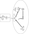
- FIG. 1 is a diagram for explaining the operation of a vehicle equipped with an in-vehicle device according to a first embodiment during communication with the outside of the vehicle.
- FIG. 2 is a diagram for explaining the operation of the vehicle shown in FIG. 1 during communication with the outside of the vehicle.
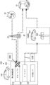
- FIG. 3 is a diagram for explaining the vehicle shown in FIG. 1.
- FIG. 4 is a block diagram showing an example of the functional configuration of the in-vehicle device according to the first embodiment.
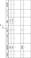
- FIG. 5 is a diagram showing an example of a relay station table.
- FIG. 6 is a block diagram showing an example of the hardware configuration of the in-vehicle device (GW device) according to the first embodiment.
- FIG. 7 is a block diagram illustrating an example of the hardware configuration of a server device that communicates with an in-vehicle device.
- FIG. 8 is a flowchart showing an example of a control structure of a program executed in the in-vehicle device shown in FIG.
- FIG. 9 is a detailed flowchart of step S1040 in FIG.
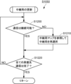
- FIG. 10 is a detailed flowchart of step S1050 in FIG. 8.
- FIG. 11 is a diagram for explaining the operation of the in-vehicle device according to the first embodiment.
- FIG. 12 is a block diagram showing an example of the functional configuration of the in-vehicle device according to the first modification.
- FIG. 13 is a block diagram illustrating an example of a functional configuration of an in-vehicle device according to a second modification.
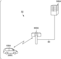
- FIG. 14 is a diagram showing the overall configuration of a security management system according to the second embodiment.
- FIG. 15 is a block diagram showing an example of the functional configuration of the in-vehicle device shown in FIG. 14.
- FIG. 16 is a block diagram showing an example of the functional configuration of the roadside machine shown in FIG. 14.
- FIG. 17 is a block diagram showing an example of the hardware configuration of the roadside machine shown in FIG. 14.
- FIG. 18 is a flowchart showing an example of a control structure of a program executed in the in-vehicle device shown in FIG. 14.
- FIG. 14 is a diagram showing the overall configuration of a security management system according to the second embodiment.
- FIG. 15 is a block diagram showing an example of the functional configuration of the in-vehicle device shown in FIG. 14.
- FIG. 16 is a block diagram showing an example of the functional configuration
- FIG. 19 is a flowchart showing an example of a control structure of a program executed in the roadside machine shown in FIG.
- FIG. 20 is a diagram showing the overall configuration of a security management system according to the third embodiment.
- FIG. 21 is a block diagram showing an example of the functional configuration of the server device shown in FIG. 20.
- FIG. 22 is a flowchart showing an example of a control structure of a program executed in the roadside machine shown in FIG. 20.
- FIG. 23 is a flowchart showing an example of a control structure of a program executed in the server device shown in FIG.
- FIG. 24 is a diagram showing the overall configuration of a security management system according to the fourth embodiment.
- FIG. 25 is a diagram showing the overall configuration of a security management system according to the fourth embodiment.
- FIG. 21 is a block diagram showing an example of the functional configuration of the server device shown in FIG. 20.
- FIG. 22 is a flowchart showing an example of a control structure of a program executed in the road
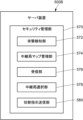
- FIG. 26 is a block diagram showing an example of the functional configuration of the server device shown in FIGS. 24 and 25.
- FIG. 27 is a flowchart showing an example of a control structure of a program executed in the server device shown in FIGS. 24 and 25.
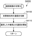
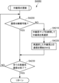
- FIG. 28 is a detailed flowchart of step S4050 in FIG. 27.
- FIG. 29 is a detailed flowchart of step S4060 in FIG. 27.
- the communication system described in Patent Document 1 relates to measures taken when an abnormality occurs in a server that provides a service.
- the measure as described above, is to cut off the communication path between the server where the abnormality has occurred and the base station device. In other words, communication with the outside is cut off for equipment in which an abnormality has occurred. Therefore, if the measure disclosed in Patent Document 1 is used as a measure when the in-vehicle device detects a cyber attack on the vehicle, communication between the in-vehicle device and the outside of the vehicle will be cut off. In this case, the necessary communications are not maintained. Therefore, the above-mentioned problem cannot be solved by the technique described in Patent Document 1.
- the present disclosure has been made to solve the above-mentioned problems, and one purpose of the present disclosure is to provide an in-vehicle device, a roadside device, an external device, and a roadside device that can maintain necessary communication even when dealing with a cyber attack.
- An object of the present invention is to provide a security management method and a computer program.
- the in-vehicle device is an in-vehicle device that is installed in a vehicle, and includes an attack detection unit that detects a cyber attack on the vehicle, and a plurality of wireless interfaces that perform wireless communication with the outside of the vehicle.
- a wireless interface management unit that manages relay stations that communicate via either wireless interface, and a relay station management unit that manages relay stations that communicate via one of the wireless interfaces.Connection to the in-vehicle device of the own vehicle is possible from among the relay stations managed by the relay station management unit.
- a relay station selection unit that selects a relay station that is suitable for cyber attacks; It includes a route switching unit that switches the communication route to a different route from the communication route when an attack is detected.
- the attack detection unit When the attack detection unit detects a cyber attack on the vehicle, it switches the communication route to a route that goes through a relay station. By switching to a communication route different from the communication route used when a cyber attack is detected, the attack route of the cyber attack is blocked. This allows you to deal with cyber-attacks. Furthermore, communication with the outside is maintained through a route that passes through the relay station, so necessary communication can be maintained.
- the plurality of wireless interfaces managed by the wireless interface management unit include a first wireless interface that communicates with the base station and a second wireless interface that communicates with the relay station, and the route switching unit
- This configuration switches the wireless interface for wireless communication with the outside of the vehicle from the first wireless interface to the second wireless interface when the attack detection unit detects a cyber attack during communication with the base station using the first wireless interface. It may be. This makes it possible to more effectively block the attack vectors of cyber attacks.
- the relay station selection unit calculates the communication requirements necessary for communication with a predetermined communication destination set in advance, and selects a relay station that can be connected to the in-vehicle device of the host vehicle.
- the configuration may also be such that a relay station that satisfies the calculated communication requirements is selected from among the relay stations managed by the relay station management unit. Thereby, for example, a relay station that satisfies the requirements for high-priority communication can be selected, making it easier to maintain necessary communication such as high-priority communication.
- the relay station management unit further manages the security strength of the relay station, and the relay station selection unit further selects the relay station based on the security strength. It may be. As a result, a relay station with high security strength can be selected, and a more secure communication route can be set as the switching destination route.
- the relay station management unit further manages a predetermined index regarding the security threat of the relay station
- the relay station selection unit further manages the predetermined index regarding the security threat.
- a configuration may also be adopted in which a relay station is selected based on the information. This also allows a more secure communication route to be set as the switching destination route.
- the relay station managed by the relay station management unit may include a mobile station and a fixed station. This makes it possible to increase the number of selectable relay stations, thereby effectively maintaining necessary communications.
- the relay station selection unit includes a relay station update unit that updates relay stations connectable to the in-vehicle device of the host vehicle, and the relay station update unit
- the vehicle may be configured to determine whether or not it is possible to continue communication with the connected relay station in the planned travel area, and select a new relay station based on the determination result. This can prevent necessary communications from being interrupted.
- the relay station management unit manages the relay stations using a relay station table that is a table of information for each relay station in the area where the vehicle is scheduled to travel, and
- the station selection unit may be configured to refer to a relay station table and select a relay station connectable to the in-vehicle device of the own vehicle in the planned travel area. This makes it easy to select a relay station that can be connected to the in-vehicle device.
- the method further includes an acquisition unit that acquires a relay station map in which relay stations that meet predetermined requirements are mapped in an area including the vehicle's scheduled travel area from an information processing device outside the vehicle,
- the station management unit may be configured to extract information about an area corresponding to the planned travel area and including a relay station table from the relay station map acquired by the acquisition unit.
- the relay station selection unit can effectively select a relay station connectable to the in-vehicle device using the extracted relay station table.
- the acquisition unit further includes an acquisition unit that acquires a relay station map that includes a relay station table and maps relay stations that meet predetermined requirements to the vehicle's scheduled travel area from an information processing device outside the vehicle.
- the configuration may include. This also makes it possible to effectively select a relay station that can be connected to the in-vehicle device.
- An in-vehicle device is an in-vehicle device installed in a vehicle, which includes an attack detection unit that detects a cyber attack on the vehicle, and a plurality of wireless interfaces that perform wireless communication with the outside of the vehicle.
- an attack detection unit detects a cyber attack on the vehicle
- a plurality of wireless interfaces perform wireless communication with the outside of the vehicle.
- the wireless interface management unit includes a route switching unit that switches the communication route to a route that passes through the designated relay station in response to an instruction from the roadside device that has received the vehicle information.
- the in-vehicle device communicates with the roadside device when a cyber attack is detected, and switches the communication route based on instructions sent from the roadside device. Cyber attacks can be dealt with by switching the communication route and cutting off the attack path of the cyber attack. Furthermore, communication with the outside is maintained through a route that passes through the relay station, so necessary communication can be maintained.
- the roadside device is a roadside device that communicates with an in-vehicle device installed in a vehicle, and when the in-vehicle device detects a cyber attack on the vehicle, the in-vehicle device detects a cyber attack.
- the roadside device transmits to the outside vehicle information that includes at least information about the communication route at the time of the vehicle and information about the wireless interface that performs wireless communication with the outside of the vehicle.
- a receiving unit that receives vehicle information, and a relay station that can be connected to an on-vehicle device in a vehicle from among the relay stations managed by a relay station management unit based on the received vehicle information, when a cyber attack is detected.
- a relay station selection unit that selects a relay station that is a different communication route from the communication route; and an instruction transmission unit that transmits an instruction to the in-vehicle device to switch the communication route to a route that passes through the relay station selected by the relay station selection unit.
- the roadside device sends an instruction to the vehicle that has detected the cyber attack to switch the communication route to a route that goes through the relay station. That is, the roadside device switches the communication path between the vehicle and the outside by remote control. This makes it possible for the vehicle to block the attack path of cyber attacks, and maintain communication with the outside via a route that goes through the relay station.
- the external device is an external device that communicates with an in-vehicle device installed in a vehicle, and includes an attack detection unit that detects a cyber attack on the vehicle, and a plurality of attack detection units installed in the vehicle.
- a relay station management unit that manages relay stations that communicate via any of the wireless interfaces of
- a relay station selection unit that selects a relay station that can be connected to the relay station, and an instruction to switch the communication route to a route that passes through the relay station selected by the relay station selection unit and that is different from the communication route at the time of detection of a cyber attack.
- an instruction transmission unit that transmits the information to the in-vehicle device.
- a device outside the vehicle remotely monitors the vehicle, and when the vehicle receives a cyber attack, the attack detection unit detects the cyber attack.
- the off-vehicle device detects a cyber attack on the vehicle, it selects a relay station that can be connected to the on-vehicle device of the vehicle that has suffered the cyber attack from among the relay stations managed by the relay station management section.
- the external device further transmits an instruction to the in-vehicle device to switch the communication path to a path that passes through the selected relay station and is different from the communication path at the time of detection of the cyber attack. This makes it possible for the vehicle to block the attack path of cyber attacks, and maintain communication with the outside via a route that goes through the relay station.
- a security management method is a security management method for an in-vehicle device installed in a vehicle, in which the in-vehicle device detects a cyber attack on the vehicle; , when a cyber attack is detected, the in-vehicle device can be connected to the in-vehicle device from a relay station that communicates via any one of a plurality of wireless interfaces that perform wireless communication with the outside of the vehicle.
- the method includes a step of selecting a relay station, and a step of the in-vehicle device switching the communication route to a route that passes through the relay station selected in the selecting step and that is different from the communication route at the time of detecting the cyber attack. . This allows you to deal with cyber-attacks. Furthermore, communication with the outside is maintained through a route that passes through the relay station, so necessary communication can be maintained.
- a computer program includes a computer installed in a vehicle, an attack detection unit that detects a cyber attack on the vehicle, and a wireless interface that manages a plurality of wireless interfaces that perform wireless communication with the outside of the vehicle.
- An interface management unit a relay station management unit that manages relay stations communicating via one of the wireless interfaces, and a relay station that can be communicatively connected to the computer from among the relay stations managed by the relay station management unit.
- the wireless interface management unit functions as a relay station selection unit, and when the attack detection unit detects a cyber attack, the wireless interface management unit provides a route that passes through the relay station selected by the relay station selection unit, and the communication at the time of detection of a cyber attack. It includes a route switching unit that switches the communication route to a different route. This allows you to deal with cyber-attacks. Furthermore, communication with the outside is maintained through a route that passes through the relay station, so necessary communication can be maintained.
- the vehicle 100 reports the occurrence of the vehicle accident to an emergency call center 10.
- Automatically notify Specifically, when the vehicle 100 causes a collision, the vehicle 100 transmits data such as identification information, status, and location information of the vehicle 100 to an emergency call center via wireless communication, using the activation of an airbag due to the collision as a trigger. automatically sent to 10.
- the identification information includes information such as the vehicle type and the color of the vehicle body.
- the status includes, for example, whether a seatbelt is worn or not, and the degree of the collision (collision sensor information indicating the severity of the collision).
- the position information includes GPS (Global Positioning System) coordinate information.
- cellular communication which is a wide area communication, is usually used for communication between the vehicle 100 and the emergency call center 10.
- the vehicle 100 communicates with a base station 20 (cellular base station), and communicates with the emergency call center 10 via the base station 20.
- wide area communications such as cellular communications allow cyber attacks to be carried out from a wide range.
- the vehicle 100 which is always connected to the emergency call center 10 through cellular communication, may be subject to a cyberattack from the attacker 30.
- one possible measure in the event of a cyberattack is to cut off all communication with the outside of the vehicle. However, in that case, communication with the emergency call center 10 is also cut off.
- vehicle 100 that has been attacked by a cyber attack switches its communication route with emergency call center 10 from a route via base station 20 to a route via relay station 40. .
- the relay station 40 includes a mobile station 40A such as a vehicle and a fixed station 40B such as an infrastructure device (roadside device).
- communication for maintaining the connection is not limited to communication with the emergency call center 10. If the communication has a relatively high priority, the connection for such communication may be maintained. Communications that require a connection to be maintained have a higher priority than communications that can be temporarily interrupted; therefore, such communications may be referred to as "high-priority communications" below. .
- Another example of high priority communication is communication with an external device for remotely controlling the vehicle 100 during automatic driving.
- the above processing in the vehicle 100 is executed by an on-vehicle device mounted on the vehicle 100.
- in-vehicle device 200 is mounted on vehicle 100 and executes various processes including the above-described processes.
- the vehicle 100 is equipped with various sensors such as a millimeter wave radar 110, an on-vehicle camera 112, and a LiDAR (Laser Imaging Detection and Ranging) 114.
- the in-vehicle device 200 collects sensor data from these sensors and wirelessly transmits it to the server device 500 as an information processing device installed outside the vehicle, or receives various information from the server device 500.
- the in-vehicle device 200 supports safe driving of the driver, for example, based on collected sensor data or information received from the server device 500.
- in-vehicle device 200 includes an in-vehicle GW (Gateway) device (hereinafter simply referred to as "GW device”) 210 and an external wireless device 300.
- GW device Gateway device
- the vehicle 100 is equipped with an in-vehicle network 400, which is a communication network including various sensors, various ECUs (Electronic Control Units), and the like.
- a vehicle is equipped with multiple in-vehicle networks.
- an in-vehicle network 400 is shown as a representative of a plurality of in-vehicle networks, and other in-vehicle networks are omitted.
- the GW device 210 interconnects a plurality of in-vehicle networks including the in-vehicle network 400 and organizes data exchange between the in-vehicle networks.
- In-vehicle network 400 includes a sensor group 410 including various sensors, and an ECU group 420 including various ECUs.
- ECU group 420 includes automatic driving ECUs.
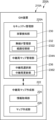
- the GW device 210 further includes a security management section 220 as a functional section.
- Security management section 220 performs security management in vehicle 100. Specifically, the security management unit 220 detects, for example, a cyber attack on the vehicle 100 and executes a process of switching the communication route with the outside of the vehicle.
- the security management unit 220 includes an attack detection unit 230, a wireless interface (hereinafter referred to as “IF”) management unit 232, a relay station map management unit 234, and a relay station selection unit 236. .
- IF wireless interface
- the attack detection unit 230 performs processing to detect a cyber attack on electronic equipment mounted on the vehicle 100.
- the method for detecting cyber attacks is arbitrary.
- a cyber attack can be detected using existing detection techniques such as IDS (Intrusion Detection System) or IPS (Intrusion Prevention System).
- IDS Intrusion Detection System
- IPS Intrusion Prevention System
- the content of communication data or the communication state is monitored, and a cyber attack is detected based on whether or not these match conditions for unauthorized access.
- the detection method by the attack detection unit 230 may be other than the above.
- the wireless IF management unit 232 manages the wireless IF included in the external wireless device 300 and controls the wireless IF according to the selection result of the relay station selection unit 236.
- the wireless IF management unit 232 includes a route switching unit 2322 that switches communication routes.
- the route switching unit 2322 switches the communication route by controlling the wireless IF according to the selection result of the relay station selection unit 236.
- the relay station map management unit 234 manages the relay stations that communicate via the wireless IF included in the external wireless device 300 using a relay station map.
- the relay station map is a map of the location information of the relay stations on map data, and includes a relay station table that manages various information about the relay stations.
- the relay station table manages vehicles or infrastructure devices (roadside devices) that meet a certain level of security strength, processing performance, and communication requirements by assigning IDs to them as relay stations.
- the relay station table includes various information about relay stations in the area where vehicle 100 is scheduled to travel.
- the relay station map is created by server device 500 (see FIG. 3) and provided to vehicle-mounted device 200 on a regular or irregular basis.
- Relay station map management section 234 includes an acquisition section 2342 that acquires the relay station map provided from server device 500.
- the relay station map management unit 234 also has a function of managing the relay station map acquired by the acquisition unit 2342.
- relay station map 240 includes relay station table 242.
- the relay station table 242 includes, for example, columns of "relay station ID”, “relay station type”, “security strength”, “belonging area”, “wireless IF”, “throughput”, and “delay time”.
- the “relay station type” column stores the type of vehicle (mobile station) or roadside device (fixed station).
- the “security strength” column stores information regarding security strength. Information regarding security strength includes, for example, firmware version, encryption method, length of encryption key, and the like.
- the "security strength” column may be configured to store ranks when security strength is ranked based on this information.
- the "belonging area” column stores the area number of the area to which each relay station belongs when the relay station map is divided into a plurality of areas.
- the “wireless IF” column stores the name of the wireless IF that the relay station has.
- the “throughput” and “delay time” columns each store the communication requirements of the corresponding wireless IF.
- the wireless IFs are stored in units of records. Therefore, communication requirements that can be provided for each wireless IF are managed.
- Server device 500 updates relay station table 242 (relay station map 240) upon receiving notification from the vehicle (mobile station).
- the roadside machine as a fixed station may be configured to transmit items necessary for the relay station table 242, such as the area to which it belongs, to the server device 500.
- the transmission frequency of the mobile station and the transmission frequency of the fixed station may be the same or different.
- the mobile station (vehicle) is configured to transmit the data more frequently than the fixed station (roadside device).
- Server device 500 also updates relay station table 242 (relay station map 240) when receiving a notification from a roadside device (fixed station). After updating the relay station map, server device 500 transmits the updated relay station map to vehicle 100.
- relay station selection section 236 selects a relay station connectable to in-vehicle device 200 from among the relay stations managed by relay station map management section 234. Specifically, when the attack detection unit 230 detects a cyber attack on the vehicle 100, the relay station selection unit 236 calculates communication requirements (for example, throughput or delay time) necessary for high priority communication, and creates a relay station map ( (relay station table) to select a relay station that is connectable to the in-vehicle device 200 and that satisfies the calculated communication requirements. If there are multiple selectable relay stations, a more secure relay station may be selected based on security strength, or a relay station may be selected based on preset priority.
- communication requirements for example, throughput or delay time
- Relay station selection section 236 includes a relay station update section 2362. If communication with a relay station cannot be continued in the area where the own vehicle is scheduled to travel, the relay station update unit 2362 refers to the relay station map and reselects a relay station with which communication is possible.
- the external wireless device 300 includes a plurality of wireless IFs (communication IFs) that perform wireless communication with the outside of the vehicle.
- the multiple wireless IFs include, for example, a wireless IF 310 for performing cellular communication with an external device (device outside the vehicle) using 5G (5th generation mobile communication system) or LTE (Long Term Evolution), and a wireless IF 310 for performing cellular communication with an external device using C-V2X. It includes a wireless IF 320 for communication and another wireless IF 330.
- Other wireless IFs 330 include, for example, local 5G. Note that the wireless IF included in the external wireless device 300 is not limited to these, and may be other than these. Further, the number of wireless IFs included in the external wireless device 300 is not limited to this.
- cellular communication 4G (LTE)/5G) and LPWA (Low Power Wide Area) are known for wide area communication
- DSRC Dedicated Short Range Communications
- C-V2X Short Area Communications
- local 5G differs from cellular 5G in that it is independently operated by companies or local governments other than carriers.
- the external wireless device 300 is monitored by the security management unit 220 of the GW device 210, and the wireless IFs 310 to 330 are controlled.
- GW device 210 includes a computer 212.
- the computer 212 communicates with a control unit 250 that controls the entire GW device 210, a storage device 260 that stores various data, an in-vehicle network communication unit 270 that communicates with the in-vehicle network, and an external wireless device 300. and a communication section 280.
- the control section 250, the storage device 260, the in-vehicle network communication section 270, and the communication section 280 are all connected to a communication bus 290, and data exchange between them is performed via the communication bus 290.
- the control unit 250 includes a calculation unit 252, a ROM (Read-Only Memory) 254 that stores a boot-up program for the computer 212, and a RAM (Random Access Memory) 256 that can be written to and read from at any time.
- the arithmetic unit 252 includes, for example, a CPU (Central Processing Unit) or an MPU (Micro Processing Unit) as an arithmetic element (processor).
- Storage device 260 includes, for example, nonvolatile memory such as flash memory.
- the ROM 254 or the storage device 260 stores software (computer programs) executed by the calculation unit 252 and various information (data).
- the above-described relay station map (relay station table) is stored in the storage device 260.
- a computer program for causing the GW device 210 to function as each functional unit of the GW device 210 according to the present disclosure is stored and distributed in a predetermined storage medium such as a DVD (Digital Versatile Disc) or a USB (Universal Serial Bus) memory. , and further transferred to the storage device 260.
- the computer program may be transmitted from an external device to the computer 212 and stored in the storage device 260 through wireless communication with the outside of the vehicle.
- the in-vehicle network communication unit 270 provides an IF for communicating with the in-vehicle network.
- the in-vehicle network communication unit 270 communicates with the in-vehicle network according to a communication protocol such as CAN (Controller Area Network).
- a plurality of in-vehicle network communication units 270 are provided corresponding to a plurality of in-vehicle networks.
- the GW device 210 (computer 212) transmits data (messages) received by one in-vehicle network communication unit from another in-vehicle network communication unit under the control of the control unit 250, thereby transmitting data between in-vehicle networks. will be relayed.
- the communication unit 280 provides an IF for communicating with the external wireless device 300.
- server device 500 includes a computer 510.
- Computer 510 includes a control unit 520, a storage device 530, and a network IF 540.
- the control unit 520 includes a CPU 522, a GPU (Graphics Processing Unit) 524, a ROM 526, and a RAM 528.
- the control unit 520, the storage device 530, and the network IF 540 are all connected to a bus 550, and data exchange between them is performed via the bus 550.
- the storage device 530 includes a nonvolatile storage device such as a flash memory or a hard disk drive.
- the storage device 530 stores computer programs to be executed by the CPU 522 and various information.
- Network IF 540 provides a connection to network 502 that allows communication with other terminals.
- the server device 500 receives information necessary for creating a relay station map (relay station table) from vehicles that can serve as relay stations and roadside machines via the network 502, and creates a relay station map or Update the station map. Server device 500 distributes the created or updated relay station map to each vehicle by, for example, broadcasting.
- a relay station map relay station table
- this program determines whether or not a cyber attack on vehicle 100 (own vehicle) is detected, and waits until the cyber attack is detected in step S1000, and in step S1000, the cyber attack is detected.
- Step S1010 is executed when it is determined that the high-priority communication has been carried out, and the high-priority communication is maintained, and unnecessary application software that does not have a high priority is turned off, or the communication function of the unnecessary application software is turned off;
- a step S1020 is executed after S1010 and calculates communication requirements necessary for high-priority communication, and a step S1020 is executed after step S1020 and refers to a relay station map (relay station table) to enable connection with the in-vehicle device 200, and
- the process includes step S1030 of selecting a relay station that satisfies the calculated communication requirements, and step S1040, which is executed after step S1030 and executes communication path switching processing.
- FIG. 9 is a detailed flow of step S1040 in FIG. 8. Referring to FIG. 9, this routine is executed after step S1100 of cutting off communication with the base station or communication partner with which the cyber attack was detected, and after step S1100, and stopping communication with the selected relay station. and step S1110 of starting and ending this routine.
- this program is executed after step S1040 and executes a relay station update process at step S1050. and terminating step S1060.
- FIG. 10 is a detailed flow of step S1050 in FIG. 8.
- this routine includes step S1200 in which it is determined whether or not communication with the currently connected relay station can be continued in the planned travel area, and the flow of control is branched depending on the determination result. This is executed when it is determined that continuation is not possible in step S1200, and the relay station map (relay station table) is referred to find a relay station that can be connected to the in-vehicle device 200 and that satisfies the calculated communication requirements.
- the relay station map relay station table
- Step S1220 includes branching the control flow depending on the determination result.
- step S1220 if it is no longer necessary to maintain the high-priority communication due to, for example, the vehicle 100 stopping, that is, if there is no problem even if the communication is disconnected, it is determined that the high-priority communication has been completed. .
- the high priority communication is completed when the vehicle 100 causes an accident and the automatic notification to the emergency notification center 10 is completed. If it is determined in step S1220 that all high priority communications have not been completed, control returns to step S1200. If it is determined in step S1220 that all high priority communications have been completed, this routine ends.
- the in-vehicle device 200 operates as follows. In the following, a case will be described in which communication with the emergency call center is set as high priority communication that requires communication to be maintained.
- vehicle 100 is communicating with base station 20 via wireless IF 310 that performs cellular communication, and is connected to emergency call center 10 via base station 20. It is assumed that the vehicle 100 is in a state of communicating with the outside of the vehicle through wide area communication, and at this time, an attacker 30 launches a cyber attack.
- step S1010 when attack detection unit 230 detects a cyber attack on vehicle 100 (YES in step S1000 of FIG. 8), security management unit 220 turns off unnecessary application software or The communication function is turned off (step S1010).
- the relay station selection unit 236 calculates communication requirements necessary for communication (high priority communication) with the emergency call center 10, which is a preset communication destination (step S1020), and refers to the relay station map (relay station table). Then, a relay station that is connectable to the in-vehicle device 200 and that satisfies the calculated communication requirements is selected from among the relay stations managed by the relay station map management unit 234 (step S1030).
- the wireless IF management unit 232 (route switching unit 2322) controls the external wireless device 300 to disconnect communication when an attack is detected and start communication with the relay station selected by the relay station selection unit 236 (see FIG. 9). Step S1100 and Step S1110).
- in-vehicle device 200 cuts off communication when an attack is detected, and switches the communication route to a route via relay station 40. Switching of the communication path is performed by switching the wireless IF. That is, the external wireless device 300 cuts off cellular communication by the wireless IF 310 and switches the wireless IF for communicating with the outside of the vehicle to the wireless IF 320 (C-V2X) that is capable of vehicle-to-vehicle communication and road-to-vehicle communication.
- the wireless IF 320 starts communication with the relay station 40 (mobile station 40A or fixed station 40B) selected by the relay station selection unit 236 (see FIG. 4), and is connected to the emergency call center 10 via the relay station 40. maintain the condition.
- the in-vehicle device 200 (GW device 210) detects a cyber attack and before cutting off cellular communication by the wireless IF 310, the in-vehicle device 200 (GW device 210) sends the relay station map to the server device 500 (see FIG. 3).
- the latest relay station map (relay station list) may be acquired from server device 500 by transmitting a transmission request.
- the in-vehicle device 200 continues communicating with the emergency call center 10 via the relay station 40 until all high-priority communications are completed, that is, until it is no longer necessary to maintain the connection with the emergency call center 10. If it is necessary to update the relay station (NO in step S1200 in FIG. 10), the vehicle-mounted device 200 refers to the relay station map and reselects an updateable relay station (step S1210). That is, the vehicle-mounted device 200 hands over the relay station depending on the communication status with the relay station.
- the in-vehicle device 200 has the relay station with which it is currently communicating transfer the latest relay station map provided by the server device 500 (see FIG. 3).
- the in-vehicle device 200 refers to the transferred relay station map (relay station table), determines the next relay station connectable to the in-vehicle device 200 in the area where the own vehicle is scheduled to travel, and hands over the relay station.
- the in-vehicle device 200 no longer needs to maintain the connection with the emergency call center 10 (YES in step S1220 in FIG. 10), it disconnects communication with the relay station (step S1060 in FIG. 8).
- the in-vehicle device 200 operates in the same manner as described above. Furthermore, if there are multiple high-priority communications, communication via the relay station is maintained until all high-priority communications are completed.
- the in-vehicle device 200 (GW device 210) according to the present embodiment has the following effects.
- the attack detection unit 230 When the attack detection unit 230 detects a cyber attack on the vehicle 100, it switches the communication route to a route via the relay station 40. By switching to a communication route different from the communication route used when a cyber attack is detected, the attack route of the cyber attack is blocked. This allows you to deal with cyber-attacks. Furthermore, since communication with the outside is maintained through the route passing through the relay station 40, necessary communication can be maintained.
- the plurality of wireless IFs managed by the wireless IF management unit 232 include a wireless IF 310 that communicates with the base station 20 and a wireless IF 320 that communicates with the relay station 40.
- the route switching unit 2322 of the wireless IF management unit 232 switches the wireless IF for wireless communication with the outside of the vehicle to a cellular
- the wireless IF 310 that performs communication is switched to the wireless IF 320 that performs vehicle-to-vehicle communication or road-to-vehicle communication. This makes it possible to more effectively block the attack vectors of cyber attacks.
- the relay station selection unit 236 is a relay station that calculates communication requirements necessary for communication with a predetermined communication destination (for example, the emergency call center 10) and is connectable to the in-vehicle device 200, and A relay station that satisfies the calculated communication requirements is selected from among the relay stations managed by the relay station map management unit 234. Thereby, for example, a relay station that satisfies the requirements for high-priority communication can be selected, making it easier to maintain necessary communication such as high-priority communication.
- the relay station map management unit 234 further manages the security strength of each relay station, and the relay station selection unit 236 further selects a relay station based on the security strength. As a result, a relay station with high security strength can be selected, and a more secure communication route can be set as the switching destination route.
- the relay stations managed by the relay station map management unit 234 include a mobile station 40A and a fixed station 40B. This makes it possible to increase the number of selectable relay stations, thereby effectively maintaining necessary communications.
- the relay station selection unit 236 includes a relay station update unit 2362 that updates relay stations that can be connected to the in-vehicle device 200, and the relay station update unit 2362 updates the relay stations that are connected to the relay station in the area where the vehicle 100 is scheduled to travel. A new relay station is selected based on the determination result. This can prevent necessary communications from being interrupted.
- the relay station map management unit 234 manages the relay stations using a relay station table (relay station map) that is a table of information for each relay station in the area where the vehicle 100 is scheduled to travel, and the relay station selection unit 236 manages the relay stations.
- a relay station table that is a table of information for each relay station in the area where the vehicle 100 is scheduled to travel
- the relay station selection unit 236 manages the relay stations. Referring to the table, a relay station that can be connected to the in-vehicle device 200 in the planned travel area is selected. This makes it easy to select a relay station that can be connected to the in-vehicle device 200. Furthermore, by using a relay station map (relay station table), seamless switching of communication paths is facilitated when a cyber attack is detected.
- the in-vehicle device 200 transmits a relay station map in which relay stations that meet predetermined requirements (for example, security strength above a certain level, processing performance, and communication requirements) are mapped to the planned driving area of the vehicle 100 from a server device 500 outside the vehicle. get.
- the acquired relay station map includes a relay station table. Thereby, a relay station connectable to the in-vehicle device 200 can be effectively selected based on the relay station map (relay station table).
- an in-vehicle device 200A includes a GW device 210A instead of the GW device 210 (see FIG. 4).
- the GW device 210A includes a security management section 220A and a relay station map creation section 222 as functional sections.
- the security management unit 220A differs from the first embodiment in that it includes a relay station map management unit 234A instead of the relay station map management unit 234 (see FIG. 4). Other configurations are similar to those of the first embodiment.
- the relay station map management unit 234A manages the relay station map created by the relay station map creation unit 222.
- the relay station map management unit 234A further manages relay stations that communicate via the wireless IF of the external wireless device using a relay station map.
- the relay station map creation section 222 includes an information acquisition section 224 and a map creation section 226.
- the information acquisition unit 224 acquires (receives) information necessary for creating a relay station map (relay station table) from a vehicle that can serve as a relay station, a roadside machine, or the like.
- the map creation unit 226 creates a relay station map based on the acquired information, or updates the created relay station map.
- the relay station map management unit 234A may be configured to further acquire a relay station map from the server device, as in the first embodiment. In this case, if the in-vehicle device 200A can acquire the relay station map from the server device, it can select the relay station using the relay station map acquired from the server device.
- the security management section 220A may include a relay station map creation section 222.
- the in-vehicle device extracts the map information necessary for the own vehicle from the relay station map information acquired from the server device, and uses the extracted map information as the relay station map. It is different from.
- an in-vehicle device 200B includes a GW device 210B instead of the GW device 210 (see FIG. 4).
- the GW device 210B includes a security management section 220B as a functional section instead of the security management section 220 (see FIG. 4).
- the security management section 220B includes a relay station map management section 234B instead of the relay station map management section 234 (see FIG. 4).
- the relay station map management unit 234B uses an acquisition unit 2342 that acquires relay station map information from a server device and filters the relay station map information acquired by the acquisition unit 2342 to obtain information necessary for the own vehicle as a relay station map. and a filtering section 2344 for extraction.
- the server device creates and distributes, for example, a wide range of relay station map information.
- the in-vehicle device 200B extracts, for example, information about the area in which the host vehicle is scheduled to travel from the extensive relay station map information distributed by the server device. Thereby, the vehicle-mounted device 200B can effectively select a relay station connectable to the vehicle-mounted device 200B using the relay station table included in the extracted relay station map.
- the in-vehicle device differs from the above-described embodiment in that the relay station is selected further based on a predetermined index regarding the security threat of the relay station.
- the relay station map management unit of the in-vehicle device further manages predetermined indicators regarding security threats to the relay station.
- the predetermined index can be, for example, an "index for evaluating the severity of vulnerability” shown in the Common Vulnerability Scoring System (CVSS).
- CVSSv3 the attack vector (AV), attack complexity (AC), required privilege level (PR), and user involvement level (UI) are used as indicators regarding the difficulty of attacks. :User interaction) are shown. Attackability is calculated using these indicators.
- the in-vehicle device selects a relay station by further considering the calculated ease of attack.
- the relay station selection unit of the in-vehicle device calculates the communication requirements necessary for communication with a predetermined communication destination (for example, an emergency call center), and selects a relay station that can be connected to the in-vehicle device of the own vehicle.
- a relay station is selected by selecting a combination of a relay station and a wireless IF that minimizes attackability from a set of relay stations that are relay stations and satisfy the calculated communication requirements.
- the relay station selection unit may select a relay station by selecting a combination of a relay station and a wireless IF whose ease of attack is below a certain value and which optimizes the calculated communication requirements.
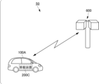
- security management system 50 includes an on-vehicle device 200C mounted on vehicle 100A, and a roadside device 600 that wirelessly communicates with vehicle 100A.
- This embodiment differs from the first embodiment in that the roadside machine 600 performs at least some of the functions of the security management unit shown in the first embodiment. Note that although one roadside machine 600 is shown in FIG. 14, there may be a plurality of roadside machines 600.
- the vehicle 100A that has detected the cyber attack transmits vehicle information to the roadside device 600 and waits for instructions from the roadside device 600.
- Management of relay stations and selection of relay stations are performed by roadside machine 600 on the infrastructure side, and roadside machine 600 selects a relay station based on vehicle information from vehicle 100A.
- Roadside device 600 transmits the selected relay station to vehicle 100A along with a communication route switching instruction.
- Vehicle 100A switches the communication route based on a switching instruction transmitted from roadside device 600.
- an on-vehicle device 200C mounted on a vehicle 100A includes a GW device 210C.
- the GW device 210C includes a security management section 220C.
- the security management section 220C includes an attack detection section 230, a wireless IF management section 232A, and a transmission section 238.
- Attack detection unit 230 detects a cyber attack on electronic equipment mounted on vehicle 100A, as in the first embodiment.
- the wireless IF management unit 232A manages the wireless IF included in the external wireless device, and also controls the wireless IF in order to perform wireless communication with the outside of the vehicle.
- the wireless IF management unit 232A includes a route switching unit 2324 that switches communication routes.
- the route switching unit 2324 switches the communication route by controlling the wireless IF in response to a switching instruction from the roadside device 600.
- the transmitting unit 238 transmits vehicle information to the roadside device 600 (see FIG. 14) in response to the attack detecting unit 230 detecting a cyber attack.
- the vehicle information transmitted by the transmitting unit 238 includes information regarding a communication route when a cyber attack is detected, and information regarding a wireless IF that performs wireless communication with the outside of the vehicle.
- the information regarding the wireless IF includes information regarding the wireless IF managed by the wireless IF management unit 232A (for example, the type of wireless IF, communication requirements for the wireless IF, etc.).
- the vehicle information may further include location information indicating the current location of the vehicle 100A, and other information such as communication requirements necessary for high priority communication.
- roadside machine 600 includes a relay station map management section 610, a reception section 620, a relay station selection section 630, and a switching instruction transmission section 640 as functional sections.
- Relay station map management section 610 manages relay stations using a relay station map.
- Relay station map management section 610 includes an acquisition section 612 that acquires a relay station map provided from, for example, a server device.
- the receiving unit 620 receives vehicle information transmitted from the in-vehicle device 200C (see FIG. 15).
- the relay station selection unit 630 selects a relay station from among the relay stations managed by the relay station map management unit 610 that can be connected to the in-vehicle device 200C in the vehicle 100A, and detects a cyber attack. Select a relay station that provides a different communication route from the current communication route.
- Switching instruction transmitting section 640 transmits an instruction to switch the communication route to a route passing through the relay station selected by relay station selecting section 630 to in-vehicle device 200C (GW device 210C).
- roadside machine 600 is substantially a processor including computer 650.
- the computer 650 includes a microprocessor 652, a ROM 654, a RAM 656, a nonvolatile storage device 658 such as a flash memory, a wireless communication unit 660 that provides communication with the outside via wireless communication, and an input/output IF 662.
- the microprocessor 652, ROM 654, RAM 656, storage device 658, wireless communication unit 660, and input/output IF 662 are all connected to a bus 664, and data exchange between them is performed via the bus 664.
- Roadside machine 600 further includes various sensors 670 connected to input/output IF 662.
- the various sensors 670 are, for example, cameras, millimeter wave sensors, or LiDAR.
- the ROM 654 or storage device 658 stores software (computer programs) executed by the microprocessor 652 and various information (data) such as relay station maps. Each functional unit in the roadside device 600 is realized by software processing executed by the microprocessor 652 using hardware.
- the roadside machine 600 acquires the relay station map from the server device by communicating with the server device via the wireless communication unit 660.
- the roadside device 600 receives information necessary for creating a relay station map (relay station table) from a vehicle that can serve as a relay station and the roadside device via the wireless communication unit 660, and creates or creates a relay station map.
- the relay station map may be updated.
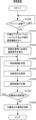
- the program shown in FIG. 18 is executed instead of the program shown in FIG. 8.
- the program of FIG. 18 includes steps S1300 to S1330 instead of steps S1030 to S1050 in the program of FIG.
- the processing in steps S1000 to S1020 and step S1060 in FIG. 18 is the same as the processing in each step shown in FIG. The different parts will be explained below.
- step S1020 This program is executed after step S1020, and collects vehicle information including information on the communication route when a cyber attack is detected, information on the wireless IF that performs wireless communication with the outside of the vehicle, and information on communication requirements necessary for high priority communication.
- step S1300 for transmitting to the roadside device 600 step S1310 executed after step S1300 and receiving the switching instruction transmitted from the roadside device 600, and step S1310 executed after step S1310 for changing the communication path based on the received switching instruction.
- step S1330 which is executed after step S1320, determines whether updating of the relay station is necessary, and branches the flow of control according to the determination result. If it is determined in step S1330 that updating of the relay station is necessary, control returns to step S1300. If it is determined in step S1330 that updating of the relay station is unnecessary, control proceeds to step S1060.
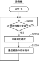
- step S2000 This program is executed in step S2000 of determining whether vehicle information has been received and waiting until the vehicle information is received, and is executed when it is determined that vehicle information has been received in step S2000, and is executed based on the received vehicle information.
- Step S2010 of selecting a relay station that is connectable to the vehicle 100A (vehicle-mounted device 200C) that transmitted the vehicle information and that satisfies the communication requirements necessary for high-priority communication based on the relay station map being managed.
- step S2020 which is executed after step S2010 and transmits a switching instruction to vehicle 100A to switch the communication route to a route via the selected relay station, and returns control to step S2000.
- the security management system 50 operates as follows.
- vehicle 100A in-vehicle device 200C
- vehicle 100A that has detected a cyber attack on its own vehicle turns off unnecessary application software or turns off the communication function of unnecessary application software (step S1010 in FIG. 18).
- the communication requirements necessary for high-priority communication are calculated (step S1020).
- the in-vehicle device 200C transmits vehicle information to the roadside device 600 (step S1300).
- the roadside device 600 When the roadside device 600 receives the vehicle information transmitted from the vehicle 100A (vehicle-mounted device 200C) (YES in step S2000 in FIG. 19), the roadside device 600 is able to connect to the vehicle 100A and performs high-priority communication based on the received vehicle information. A relay station that satisfies the necessary communication requirements is selected with reference to the relay station map (step S2010). The roadside device 600 transmits a switching instruction to the vehicle 100A (vehicle device 200C) to switch the communication route to a route via the selected relay station (step S2020).
- the vehicle-mounted device 200C switches the communication path based on the switching instruction (step S1320). Specifically, communication is cut off when an attack is detected, and communication with the relay station specified by the switching instruction is started. If it is necessary to update the relay station (YES in step S1330), the vehicle information is transmitted to other roadside devices 600 via road-to-vehicle communication. The other roadside device 600 that has received the vehicle information selects a relay station and transmits a communication path switching instruction to the vehicle 100A (steps S2010 and S2020 in FIG. 19).
- vehicle 100A vehicle-mounted device 200C
- vehicle 100A vehicle-mounted device 200C
- the in-vehicle device 200C since communication is disconnected when an attack is detected, the in-vehicle device 200C only executes the update process for the relay station.
- the in-vehicle device 200C disconnects communication with the relay station (step S1060).
- roadside machine 600 transmits an instruction to vehicle 100A that has detected a cyber attack to switch the communication route to a route via a relay station. That is, roadside device 600 switches the communication path with the outside in vehicle 100A by remote control. As a result, in the vehicle 100A, it is possible to block the attack route of a cyber attack, and to maintain communication with the outside through a route via the relay station.
- the configuration shown in the second embodiment may be combined with the in-vehicle device according to the first embodiment and its modifications. That is, in the in-vehicle device according to the first embodiment and its modification, the communication path may be switched according to a switching instruction from the roadside device 600, as necessary.
- a security management system 52 includes an on-vehicle device 200C mounted on a vehicle 100A, a roadside device 600A that wirelessly communicates with the vehicle 100A, and a vehicle 100A via the roadside device 600A. and a server device 500A to communicate with.
- This embodiment differs from the first and second embodiments in that the server device 500A performs at least some of the functions of the security management unit shown in the first embodiment.
- one roadside machine 600A is shown in FIG. 20, there may be a plurality of roadside machines 600A as in the second embodiment.
- the roadside machine 600A communicates with the server device 500A by wire or wirelessly.
- roadside machine 600A is wired to server device 500A via communication line 60.
- the vehicle 100A that has detected the cyber attack transmits vehicle information to the roadside device 600A.
- the roadside device 600A transmits the received vehicle information to the server device 500A.
- Management of relay stations and selection of relay stations are performed by server device 500A, which is an infrastructure-side device outside the vehicle, and server device 500A selects a relay station based on vehicle information from vehicle 100A.
- the server device 500A transmits the selected relay station along with a communication path switching instruction to the vehicle 100A via the roadside device 600A.
- Vehicle 100A switches communication paths based on a switching instruction transmitted from server device 500A.
- An on-vehicle device 200C mounted on the vehicle 100A has a configuration similar to that of the second embodiment.
- the roadside device 600A has a function as a relay station that relays communication between the in-vehicle device 200C and the server device 500A.
- the function as a security management unit is provided by the server device 500A instead of the roadside device 600A.
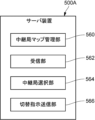
- server device 500A includes a relay station map management section 560, a reception section 562, a relay station selection section 564, and a switching instruction transmission section 566 as functional sections.
- Relay station map management section 560 creates a relay station map and manages the relay stations using the created relay station map.
- the receiving unit 562 receives vehicle information transmitted from the in-vehicle device 200C (see FIG. 15) via the roadside device 600A. Based on the received vehicle information, the relay station selection unit 564 selects a relay station from among the relay stations managed by the relay station map management unit 560 that can be connected to the in-vehicle device 200C in the vehicle 100A, and detects a cyber attack.
- the switching instruction transmitting unit 566 transmits an instruction to switch the communication route to a route passing through the relay station selected by the relay station selecting unit 564 to the in-vehicle device 200C (GW device 210C) via the roadside device 600A.
- the hardware configuration of the server device 500A is similar to the hardware configuration of the server device 500 shown in FIG.
- this program determines whether vehicle information from vehicle 100A (see FIG. 20) has been received, and branches the flow of control according to the determination result; , step S2110 is executed when it is determined that vehicle information has not been received, determines whether a switching instruction has been received from the server device 500A, and branches the flow of control according to the determination result. . If it is determined in step S2110 that a switching instruction has not been received, control returns to step S2100.
- step S2100 This program is further executed when it is determined in step S2100 that vehicle information has been received, and in step S2120, the received vehicle information is transmitted to the server device 500A, and in step S2110, it is determined that a switching instruction has been received.
- Step S2130 is executed when the switching instruction is received and transmits the received switching instruction to the vehicle 100A.
- This program is started, for example, in response to an operation by an administrator.
- This program determines whether vehicle information has been received from the roadside device 600A (see FIG. 20), and waits until vehicle information is received in step S3000, and in step S3000, it is determined that vehicle information has been received.
- a relay that manages a relay station that is connectable to the vehicle 100A (vehicle-mounted device 200C) that transmitted the vehicle information and that satisfies the communication requirements necessary for high-priority communication, based on the received vehicle information.
- the security management system 52 operates as follows.
- the vehicle 100A in-vehicle device 200C
- the vehicle 100A that has detected a cyber attack on its own vehicle turns off unnecessary application software or turns off the communication function of unnecessary application software necessary for high-priority communication. Calculate communication requirements.
- the in-vehicle device 200C transmits vehicle information to the roadside device 600A.
- the roadside device 600A When the roadside device 600A receives the vehicle information (YES in step S2100 of FIG. 22), the roadside device 600A transmits the received vehicle information to the server device 500A (step S2120).
- the server device 500A receives the vehicle information transmitted from the vehicle 100A (vehicle device 200C) via the roadside device 600A (YES in step S3000 of FIG. 23), the server device 500A can connect to the vehicle 100A based on the received vehicle information. , and a relay station that satisfies the communication requirements necessary for high-priority communication is selected with reference to the relay station map (step S3010).
- the server device 500A transmits a switching instruction to switch the communication route to a route via the selected relay station to the roadside device 600A (step S3020).
- the roadside device 600A When the roadside device 600A receives the switching instruction from the server device 500A (YES in step S2110 of FIG. 22), the roadside device 600A transmits the received switching instruction to the vehicle 100A (vehicle device 200C) (step S2130).
- the vehicle-mounted device 200C switches the communication path based on the switching instruction. Specifically, communication is cut off when an attack is detected, and communication with the relay station specified by the switching instruction is started. When it is necessary to update the relay station, vehicle information is transmitted to another roadside device 600A through road-to-vehicle communication.
- the other roadside device 600A that has received the vehicle information transmits the vehicle information to the server device 500A, receives the switching instruction from the server device 500A, and transmits it to the vehicle 100A.
- vehicle 100A vehicle-mounted device 200C
- vehicle 100A vehicle-mounted device 200C
- the in-vehicle device 200C disconnects communication with the relay station.
- server device 500A transmits an instruction to switch the communication route to a route via a relay station to vehicle 100A that has detected a cyber attack. That is, the server device 500A switches the communication path with the outside in the vehicle 100A by remote control. As a result, in the vehicle 100A, it is possible to block the attack route of a cyber attack, and to maintain communication with the outside through a route via the relay station.
- the relay station that relays communication between the in-vehicle device and the server device may be a vehicle (mobile station) in addition to the roadside device (fixed station). That is, the security management system 52 according to the present embodiment may include a vehicle (mobile station) instead of the roadside machine (fixed station). Alternatively, the configuration may include both a roadside device (fixed station) and a vehicle (mobile station).
- the server device 500A having the function of the security management section may be a server device of an emergency call center, or may be a server device different from the server device of the emergency call center.
- the security management system differs from the first embodiment in that the server device performs vehicle security management, and the vehicle security management system uses an in-vehicle device to perform vehicle security management.
- the security management system includes a server device that remotely manages vehicle security.
- the server device which is an external device, not only remotely monitors the vehicle by communicating with the on-vehicle device installed in the vehicle, but also remotely controls the vehicle and changes the communication path in the vehicle when the vehicle is subjected to a cyber attack. Switch.
- security management system 54 includes a server device 500B.
- Server device 500B communicates with vehicle 100B (vehicle device 200D). Communication between server device 500B and vehicle 100B may be wide area communication such as cellular communication, or communication via a relay station. Vehicle 100B transmits communication data, observation results such as communication status, or information for detecting cyber attacks such as communication logs to server device 500B at regular intervals or at arbitrary timing.
- the server device 500B remotely monitors the vehicle 100B and has a function of detecting that the monitored vehicle 100B has been subjected to a cyber attack based on this information. Communication between server device 500B and vehicle 100B after detecting a cyber attack can be communication via a relay station.
- server device 500B when server device 500B detects that vehicle 100B has been subjected to a cyber attack, server device 500B uses remote control to change the communication path between vehicle 100B and emergency call center 10 via base station 20.
- the route is switched from the route that passes through the relay station 40 to the route that passes through the relay station 40. Thereby, the connection with the emergency call center 10 is maintained while blocking the attack route of the cyber attack.
- server device 500B includes a security management section 570 as a functional section.
- Security management unit 570 remotely executes security management of vehicle 100B. Specifically, security management unit 570 detects, for example, a cyber attack on vehicle 100B, and executes a process of switching the communication route between vehicle 100B and the outside of the vehicle.
- Security management unit 570 includes an attack detection unit 572, a relay station map management unit 574, a reception unit 576, a relay station selection unit 578, and a switching instruction transmission unit 580 as functional units.
- the attack detection unit 572 remotely monitors the communication state, communication log, etc. in the vehicle 100B to detect when the vehicle 100B is subjected to a cyber attack.
- the relay station map management unit 574 creates a relay station map and manages the relay stations using the created relay station map.
- Receiving unit 576 receives vehicle information transmitted from in-vehicle device 200D (see FIGS. 24 and 25) mounted on vehicle 100B. Based on the received vehicle information, the relay station selection unit 578 selects a relay station from among the relay stations managed by the relay station map management unit 574 that can be connected to the in-vehicle device 200D in the vehicle 100B, and detects a cyber attack. Select a relay station that provides a different communication route from the current communication route.
- Switching instruction transmitting section 580 remotely switches the communication route in vehicle 100B by transmitting an instruction to switch the communication route to the route via the relay station selected by relay station selection section 578 to in-vehicle device 200D.
- the hardware configuration of the server device 500B is also similar to the hardware configuration of the server device 500 shown in FIG.
- this program remotely transmits data to vehicle 100B based on information (information for detecting cyber attacks such as communication logs) transmitted from in-vehicle device 200D (see FIGS. 24 and 25).
- Step S4000 which is executed after step S4000
- step S4010 which is executed after step S4000, determines whether or not the vehicle 100B to be monitored has been subjected to a cyber attack. If it is determined in step S4010 that the vehicle 100B to be monitored has not been attacked by a cyber attack, control returns to step S4000, and the processes of step S4000 and step S4010 are repeated until it is determined that the vehicle 100B to be monitored has been attacked by a cyber attack.
- step S4010 This program is further executed in step S4010 when it is determined that the vehicle 100B to be monitored has been subjected to a cyber attack, and high-priority communication in the vehicle 100B is performed by remote control of the vehicle 100B (see FIGS. 24 and 25).
- a step S4020 that maintains communication and turns off unnecessary application software that does not have a high priority or turns off the communication function of unnecessary application software, and a communication requirement that is executed after step S4020 and is necessary for high priority communication.
- step S4030 which is executed after step S4030, and which refers to a relay station map (relay station table) and selects a relay station that is connectable to the in-vehicle device 200D and that satisfies the calculated communication requirements.
- step S4050 which is executed after step S4040 and executes communication path switching processing in vehicle 100B by remote control of vehicle 100B.
- FIG. 28 is a detailed flow of step S4050 in FIG. 27.
- this routine includes step S4100 of remotely controlling vehicle 100B (see FIGS. 24 and 25) to disconnect communication with the base station or communication partner with which the cyber attack was detected;
- the routine includes step S4110, which is executed after step S4100 and starts communication with the selected relay station by remote control of vehicle 100B, and ends this routine.
- this program includes step S4060, which is executed after step S4050 and executes a relay station update process in vehicle 100B by remote control of vehicle 100B; step S4070 of disconnecting communication with the relay station in vehicle 100B and terminating this program by remote control of vehicle 100B.
- FIG. 29 is a detailed flow of step S4060 in FIG. 27.
- this routine includes step S4200 in which it is determined whether communication with the currently connected relay station can be continued in the planned travel area, and the control flow is branched depending on the determination result. This is executed when it is determined in step S4200 that it is not possible to continue, and the relay station map (relay station table) is referred to to determine whether the in-vehicle device 200D (see FIGS. 24 and 25) is connectable and calculated.
- step S4200 in which it is determined whether communication with the currently connected relay station can be continued in the planned travel area, and the control flow is branched depending on the determination result. This is executed when it is determined in step S4200 that it is not possible to continue, and the relay station map (relay station table) is referred to to determine whether the in-vehicle device 200D (see FIGS. 24 and 25) is connectable and calculated.
- the relay station map relay station table
- step S4210 of reselecting a relay station that satisfies the selected communication requirements; and step S4210, which is executed after step S4210, starts communication with the reselected relay station by remote control of vehicle 100B (see FIGS. 24 and 25). If it is determined in step S4220 and step S4200 that communication with the relay station can be continued, or after step S4220, it is determined whether all high-priority communications have been completed, and the determination result is Step S4230 of branching the flow of control depending on the flow of control.
- Server device 500B remotely monitors vehicle 100B, and when vehicle 100B receives a cyber attack, attack detection unit 572 detects the cyber attack.
- the server device 500B detects a cyber attack on the vehicle 100B, it selects a relay station connectable to the on-vehicle device 200D of the vehicle that has suffered the cyber attack from among the relay stations managed by the relay station map management unit 574.
- the server device 500B further transmits an instruction to the in-vehicle device 200D of the vehicle 100B to switch the communication route to a route that passes through the selected relay station and is different from the communication route at the time of detection of the cyber attack.
- it is possible to block the attack route of a cyber attack, and to maintain communication with the outside through a route via the relay station.
- server device 500B having the function of the security management section may be a server device of an emergency call center, or may be a server device different from the server device of the emergency call center.
- the GW device has the function of a security management unit, but the present disclosure is not limited to such an embodiment.
- the external wireless device may have the function of a security management section.
- the GW device since the wireless device outside the vehicle is easily exposed to security threats, it is desirable to provide the GW device with the function of a security management section to monitor and control the wireless device outside the vehicle, as described above.
- a redundant configuration may be adopted in which both the GW device and the external wireless device are provided with the function of a security management section so that they are mutually monitored and controlled. This allows security measures to be further strengthened.
- the in-vehicle device includes a GW device and an external wireless device, but the present disclosure is not limited to such an embodiment.
- the in-vehicle device may be, for example, an ECU other than the GW device and the external wireless device. That is, the ECU may have the function of a security management section. Further, a dedicated ECU having the function of a security management section may be installed in the vehicle as an on-vehicle device. Furthermore, a plurality of in-vehicle devices may be equipped with security management units and may be configured to mutually monitor each other as described above.
- the communication cutoff when an attack is detected may be either a cutoff of communication with a base station or a cutoff of communication with a communication partner.
- the wireless IF (communication path) used at the time of attack detection may not be used for communication with the switching destination. However, if the only wireless IF that satisfies the communication requirements is the wireless IF used at the time of attack detection, this wireless IF may be used for communication with the switching destination.
- the communication requirements necessary for high-priority communication are calculated when switching the communication path, and a relay station that satisfies the communication requirements is selected.
- calculation of communication requirements necessary for high priority communication may be omitted by selecting a relay station that satisfies certain communication requirements.
- the CVSS index is used as a predetermined index regarding security threats, but the present disclosure is not limited to such an embodiment.
- the index regarding the security threat may be an index other than CVSS.
- each process (each function) of the above-described embodiment may be realized by a processing circuit including one or more processors.
- the processing circuit may include an integrated circuit or the like in which one or more memories, various analog circuits, and various digital circuits are combined.
- the one or more memories store programs (instructions) that cause the one or more processors to execute each of the above processes.
- the one or more processors may execute each of the above processes according to the program read from the one or more memories, or may execute each of the above processes according to a logic circuit designed in advance to execute each of the above processes. May be executed.
- the above processor includes a CPU, GPU, DSP (Digital Signal Processor), FPGA (Field Programmable Gate Array), and ASIC (Application Specific Integration).
- Various processors suitable for computer control may be used.
- the plurality of physically separated processors may cooperate with each other to execute each of the above processes.
- the processors installed in each of a plurality of physically separated computers cooperate with each other via a network such as a LAN (Local Area Network), WAN (Wide Area Network), or the Internet to execute the above processes. You can.
Landscapes
- Engineering & Computer Science (AREA)
- Computer Networks & Wireless Communication (AREA)
- Signal Processing (AREA)
- Computer Security & Cryptography (AREA)
- Physics & Mathematics (AREA)
- General Physics & Mathematics (AREA)
- Mobile Radio Communication Systems (AREA)
Abstract
Description
特許文献1に記載の通信システムは、サービスを提供するサーバに異常が生じた場合の措置に関する。その措置は、上記のように、異常が生じたサーバと基地局装置との間の通信経路を遮断するものである。すなわち、異常が生じた機器については外部との通信を遮断するものである。そのため、車両に対するサイバー攻撃を車載装置が検知した場合の措置として、特許文献1の措置を用いた場合、車載装置における車外との通信が遮断されることになる。この場合、必要な通信は維持されない。したがって、特許文献1に記載の技術によっては上記した問題は解決できない。
本開示によれば、サイバー攻撃に対処する場合でも必要な通信を維持できる車載装置、路側機、車外装置、セキュリティ管理方法、およびコンピュータプログラムを提供できる。
本開示の好適な実施形態を列記して説明する。以下に記載する実施形態の少なくとも一部を任意に組合せてもよい。
本開示の実施形態に係る車載装置、路側機、車外装置、セキュリティ管理方法、およびコンピュータプログラムの具体例を、以下に図面を参照しつつ説明する。なお、以下の実施の形態では、同一の部品には同一の参照番号を付してある。それらの機能および名称も同一である。したがって、それらについての詳細な説明は繰返さない。
[全体構成]
図1を参照して、eCallサービスを提供する自動緊急通報システムでは、車外との通信機能を持つ車両100が衝突事故を起こした際に、当該車両100が車両事故の発生を緊急通報センター10に自動通報する。具体的には、車両100が衝突事故を起こすと、衝突によるエアバックの作動等をトリガーとして、車両100が、当該車両100の識別情報、状態、位置情報等のデータを無線通信により緊急通報センター10に自動的に送信する。識別情報は、車種、車体の色等の情報を含む。状態は、例えばシートベルト装着の有無、および、衝突の程度(衝突の激しさを示す衝突センサ情報)等である。位置情報は、GPS(Global Positioning System)座標情報を含む。
図3を参照して、本実施の形態に係る車載装置200は車両100に搭載され、上記処理を含む種々の処理を実行する。車両100には、車載装置200に加えて、ミリ波レーダ110、車載カメラ112、LiDAR(Laser Imaging Detection and Ranging)114等の各種のセンサが搭載される。車載装置200は、例えば、これらセンサからセンサデータを収集して、車外に設置される情報処理装置としてのサーバ装置500に無線送信したり、サーバ装置500から種々の情報を受信したりする。車載装置200は、収集したセンサデータ、またはサーバ装置500から受信した情報に基づいて、例えば運転者の安全運転を支援する。
図6を参照して、GW装置210はコンピュータ212を含む。コンピュータ212は、GW装置210全体を制御する制御部250と、種々のデータを記憶する記憶装置260と、車内ネットワークとの通信を行う車内ネットワーク通信部270と、車外無線装置300との通信を行う通信部280とを含む。制御部250、記憶装置260、車内ネットワーク通信部270、および通信部280はいずれも通信バス290に接続されており、相互間のデータ交換は通信バス290を介して行われる。
図7を参照して、サーバ装置500は、コンピュータ510を含む。コンピュータ510は、制御部520と、記憶装置530と、ネットワークIF540とを含む。制御部520は、CPU522、GPU(Graphics Processing Unit)524、ROM526、およびRAM528を含む。制御部520、記憶装置530、およびネットワークIF540はいずれもバス550に接続されており、相互間のデータ交換はバス550を介して行われる。
図8から図10を参照して、サイバー攻撃を受けた場合でも必要な通信を維持するために、車載装置200(GW装置210)において実行されるコンピュータプログラムの制御構造について説明する。このプログラムは、例えば車外との無線通信の開始に伴い開始する。以下において、車載装置200は最新の中継局マップをサーバ装置500から取得しているものとする。
本実施の形態に係る車載装置200は以下のように動作する。以下では、緊急通報センターとの通信を、通信を維持する必要がある高優先通信とした場合について説明する。
以上の説明から明らかなように、本実施の形態に係る車載装置200(GW装置210)は以下に述べる効果を奏する。
上記実施の形態では、サーバ装置が中継局マップを管理し、車両に対して配信する例について示した。しかし、本開示はそのような実施の形態には限定されない。例えば、車載装置が中継局マップを構築して管理するように構成されてもよい。第1の変形例では、このような機能を持つ車載装置について説明する。
第2の変形例に係る車載装置は、サーバ装置から取得した中継局マップ情報から自車両に必要なマップ情報を抽出し、抽出したマップ情報を中継局マップとして用いる点において、上記した実施の形態とは異なる。
第3の変形例に係る車載装置は、中継局のセキュリティ脅威に関する所定の指標にさらに基づいて中継局を選択する点において、上記した実施の形態とは異なる。
図14を参照して、本実施の形態に係るセキュリティ管理システム50は、車両100Aに搭載される車載装置200Cと、車両100Aと無線通信する路側機600とを含む。本実施の形態では、第1の実施の形態において示したセキュリティ管理部の少なくとも一部の機能を路側機600が実施する点において、第1の実施の形態とは異なる。なお、図14には、1つの路側機600が示されているが、路側機600は複数であってもよい。
図17を参照して、路側機600は実質的にコンピュータ650を含むプロセッサである。コンピュータ650は、マイクロプロセッサ652、ROM654、RAM656、フラッシュメモリ等の不揮発性の記憶装置658、無線通信により外部との通信を提供する無線通信部660、および入出力IF662を含む。マイクロプロセッサ652、ROM654、RAM656、記憶装置658、無線通信部660、および入出力IF662はいずれもバス664に接続されており、相互間のデータ交換はバス664を介して行われる。路側機600はさらに、入出力IF662に接続された各種センサ670を含む。各種センサ670は、例えば、カメラ、ミリ波センサ、またはLiDARである。
本実施の形態に係る車載装置200Cでは、図8に示されるプログラムに代えて、図18に示されるプログラムが実行される。図18のプログラムは、図8のプログラムにおいて、ステップS1030からステップS1050に代えて、ステップS1300からステップS1330を含む。図18のステップS1000からステップS1020、およびステップS1060における処理は、図8に示される各ステップにおける処理と同じである。以下、異なる部分について説明する。
本実施の形態に係るセキュリティ管理システム50は以下のように動作する。
本実施の形態では、路側機600が、サイバー攻撃を検知した車両100Aに対して、中継局を経由する経路に通信経路を切替える指示を送信する。すなわち、路側機600は、遠隔制御により車両100Aにおける外部との通信経路を切替える。これにより、車両100Aにおいて、サイバー攻撃の攻撃経路を遮断できるとともに、中継局を経由する経路により外部との通信と維持できる。
図20を参照して、本実施の形態に係るセキュリティ管理システム52は、車両100Aに搭載される車載装置200Cと、車両100Aと無線通信する路側機600Aと、路側機600Aを介して車両100Aと通信するサーバ装置500Aとを含む。本実施の形態では、第1の実施の形態において示したセキュリティ管理部の少なくとも一部の機能をサーバ装置500Aが実施する点において、第1および第2の実施の形態とは異なる。図20は、路側機600Aが1つ示されているが、第2の実施の形態と同様、路側機600Aは複数であってもよい。
本実施の形態に係る路側機600Aでは、図19に示されるプログラムに代えて、図22に示されるプログラムが実行される。
本実施の形態に係るセキュリティ管理システム52は以下のように動作する。
本実施の形態では、サーバ装置500Aが、サイバー攻撃を検知した車両100Aに対して、中継局を経由する経路に通信経路を切替える指示を送信する。すなわち、サーバ装置500Aは、遠隔制御により車両100Aにおける外部との通信経路を切替える。これにより、車両100Aにおいて、サイバー攻撃の攻撃経路を遮断できるとともに、中継局を経由する経路により外部との通信と維持できる。
本実施の形態に係るセキュリティ管理システムは、サーバ装置において車両のセキュリティ管理を行う点において、車載装置において車両のセキュリティ管理を行う第1の実施の形態とは異なる。具体的には、セキュリティ管理システムは、遠隔にて車両のセキュリティ管理を行うサーバ装置を含む。車外装置であるサーバ装置は、車両に搭載される車載装置と通信して当該車両を遠隔監視するととものに、車両がサイバー攻撃を受けた際に当該車両を遠隔制御して車両における通信経路を切替える。
図27から図29を参照して、遠隔にて車両100B(図24および図25参照)のセキュリティ管理を行うために、サーバ装置500Bにおいて実行されるコンピュータプログラムの制御構造について説明する。このプログラムは、例えば管理者の操作に応じて開始する。
サーバ装置500Bは遠隔にて車両100Bを監視しており、車両100Bがサイバー攻撃を受けると、攻撃検知部572が当該サイバー攻撃を検知する。サーバ装置500Bは、車両100Bに対するサイバー攻撃を検知すると、中継局マップ管理部574が管理する中継局のなかから、サイバー攻撃を受けた車両の車載装置200Dと接続可能な中継局を選択する。サーバ装置500Bはさらに、選択した中継局を経由する経路であって、サイバー攻撃の検知時の通信経路とは異なる経路に通信経路を切替える指示を車両100Bの車載装置200Dに送信する。これにより、車両100Bにおいて、サイバー攻撃の攻撃経路を遮断できるとともに、中継局を経由する経路により外部との通信と維持できる。
上記実施の形態では、GW装置にセキュリティ管理部の機能を持たせた例について示したが、本開示はそのような実施の形態には限定されない。例えば、車外無線装置にセキュリティ管理部の機能を持たせてもよい。ただし、車外無線装置はセキュリティ脅威に晒され易いため、上記のように、GW装置にセキュリティ管理部の機能を持たせて、車外無線装置を監視し制御する構成とするのが望ましい。さらに、GW装置および車外無線装置の両方にセキュリティ管理部の機能を持たせて互いに監視の対象および制御の対象とする冗長化構成としてもよい。これにより、セキュリティ対策をより強化できる。
20 基地局
30 攻撃者
40 中継局
40A 移動局
40B 固定局
50、52、54 セキュリティ管理システム
60 通信線
100、100A、100B 車両
110 ミリ波レーダ
112 車載カメラ
114 LiDAR
200、200A、200B、200C、200D 車載装置
210、210A、210B、210C GW装置
212、510、650 コンピュータ
220、220A、220B、220C、570 セキュリティ管理部
222 中継局マップ作成部
224 情報取得部
226 マップ作成部
230、572 攻撃検知部
232、232A 無線IF管理部
234、234A、234B、560、574、610 中継局マップ管理部
236、564、578、630 中継局選択部
238 送信部
240 中継局マップ
242 中継局テーブル
250、520 制御部
252 演算部
254、526、654 ROM
256、528、656 RAM
260、530、658 記憶装置
270 車内ネットワーク通信部
280 通信部
290 通信バス
300 車外無線装置
310、320、330 無線IF
400 車内ネットワーク
410 センサ群
420 ECU群
500、500A、500B サーバ装置
502 ネットワーク
522 CPU
524 GPU
540 ネットワークIF
550、664 バス
600、600A 路側機
612、2342 取得部
562、576、620 受信部
566、580、640 切替指示送信部
652 マイクロプロセッサ
660 無線通信部
662 入出力IF
670 各種センサ
2322、2324 経路切替部
2344 フィルタリング部
2362 中継局更新部
Claims (15)
- 車両に搭載される車載装置であって、
前記車両に対するサイバー攻撃を検知する攻撃検知部と、
車外との無線通信を行う複数の無線インターフェイスを管理する無線インターフェイス管理部と、
いずれかの前記無線インターフェイスを介して通信する中継局を管理する中継局管理部と、
前記中継局管理部が管理する中継局のなかから前記車載装置と接続可能な中継局を選択する中継局選択部とを含み、
前記無線インターフェイス管理部は、前記攻撃検知部が前記サイバー攻撃を検知した場合に、前記中継局選択部が選択した中継局を経由する経路であって、前記サイバー攻撃の検知時の通信経路とは異なる経路に通信経路を切替える経路切替部を含む、車載装置。 - 前記無線インターフェイス管理部が管理する複数の前記無線インターフェイスは、基地局と通信する第1の無線インターフェイス、および中継局と通信する第2の無線インターフェイスを含み、
前記経路切替部は、前記第1の無線インターフェイスによる基地局との通信時に前記攻撃検知部が前記サイバー攻撃を検知した場合に、車外との無線通信を行う前記無線インターフェイスを前記第1の無線インターフェイスから前記第2の無線インターフェイスに切替える、請求項1に記載の車載装置。 - 前記中継局選択部は、予め設定された所定の通信先との通信に必要な通信要件を算出し、前記車載装置と接続可能な中継局であって、かつ、算出した前記通信要件を満たす中継局を、前記中継局管理部が管理する中継局のなかから選択する、請求項1または請求項2に記載の車載装置。
- 前記中継局管理部は、中継局のセキュリティ強度についてさらに管理し、
前記中継局選択部はさらに、前記セキュリティ強度に基づいて中継局を選択する、請求項1から請求項3のいずれか1項に記載の車載装置。 - 前記中継局管理部は、中継局のセキュリティ脅威に関する所定の指標についてさらに管理し、
前記中継局選択部はさらに、セキュリティ脅威に関する前記所定の指標に基づいて中継局を選択する、請求項1から請求項4のいずれか1項に記載の車載装置。 - 前記中継局管理部が管理する中継局は、移動局および固定局を含む、請求項1から請求項5のいずれか1項に記載の車載装置。
- 前記中継局選択部は、前記車載装置と接続可能な中継局を更新する中継局更新部を含み、
前記中継局更新部は、前記車両の走行予定エリアにおいて、接続中の中継局との通信が継続可能か否かを判定し、判定結果に応じて、新たな中継局を選択する、請求項1から請求項6のいずれか1項に記載の車載装置。 - 前記中継局管理部は、前記車両の走行予定エリアにおける中継局ごとの情報をテーブル化した中継局テーブルを用いて中継局を管理し、
前記中継局選択部は、前記中継局テーブルを参照して、前記走行予定エリアにおいて前記車載装置と接続可能な中継局を選択する、請求項1から請求項7のいずれか1項に記載の車載装置。 - 所定の要件を満たす中継局を前記車両の走行予定エリアを含むエリアにマップ化した中継局マップを車外の情報処理装置から通信により取得する取得部をさらに含み、
前記中継局管理部は、前記取得部が取得した中継局マップから前記走行予定エリアに対応するエリアの情報であって、前記中継局テーブルを含む情報を抽出する、請求項8に記載の車載装置。 - 前記中継局テーブルを含み、所定の要件を満たす中継局を前記車両の走行予定エリアにマップ化した中継局マップを車外の情報処理装置から通信により取得する取得部をさらに含む、請求項8に記載の車載装置。
- 車両に搭載される車載装置であって、
前記車両に対するサイバー攻撃を検知する攻撃検知部と、
車外との無線通信を行う複数の無線インターフェイスを管理する無線インターフェイス管理部と、
前記攻撃検知部が前記サイバー攻撃を検知した場合に、前記サイバー攻撃の検知時の通信経路に関する情報、および前記無線インターフェイス管理部が管理する無線インターフェイスに関する情報を含む車両情報を車外の路側機に送信する送信部とを含み、
前記無線インターフェイス管理部は、前記車両情報を受信した路側機からの指示に応じて、指示された中継局を経由する経路に通信経路を切替える経路切替部を含む、車載装置。 - 車両に搭載された車載装置と通信する路側機であって、
前記車載装置は、前記車両に対するサイバー攻撃を検知した場合に、前記サイバー攻撃の検知時の通信経路に関する情報、および車外との無線通信を行う無線インターフェイスに関する情報を少なくとも含む車両情報を外部に送信し、
前記路側機は、
中継局を管理する中継局管理部と、
前記車載装置から送信される前記車両情報を受信する受信部と、
受信した前記車両情報に基づいて、前記中継局管理部が管理する中継局のなかから、車両における前記車載装置と接続可能な中継局であって、前記サイバー攻撃の検知時の通信経路とは異なる経路となる中継局を選択する中継局選択部と、
前記中継局選択部が選択した中継局を経由する経路に通信経路を切替える指示を前記車載装置に対して送信する指示送信部とを含む、路側機。 - 車両に搭載された車載装置と通信する車外装置であって、
前記車両に対するサイバー攻撃を検知する攻撃検知部と、
前記車両に搭載される複数の無線インターフェイスのいずれかを介して通信する中継局を管理する中継局管理部と、
前記攻撃検知部が前記車両に対するサイバー攻撃を検知した場合に、前記中継局管理部が管理する中継局のなかから前記車載装置と接続可能な中継局を選択する中継局選択部と、
前記中継局選択部が選択した中継局を経由する経路であって、前記サイバー攻撃の検知時の通信経路とは異なる経路に通信経路を切替える指示を前記車載装置に送信する指示送信部とを含む、車外装置。 - 車両に搭載される車載装置におけるセキュリティ管理方法であって、
車載装置が、前記車両に対するサイバー攻撃を検知するステップと、
前記検知するステップにおいて、前記サイバー攻撃が検知された場合に、車載装置が、車外との無線通信を行う複数の無線インターフェイスのうちのいずれかの無線インターフェイスを介して通信する中継局のなかから前記車載装置と接続可能な中継局を選択するステップと、
車載装置が、前記選択するステップにおいて選択された中継局を経由する経路であって、前記サイバー攻撃の検知時の通信経路とは異なる経路に通信経路を切替えるステップとを含む、セキュリティ管理方法。 - 車両に搭載されるコンピュータを、
前記車両に対するサイバー攻撃を検知する攻撃検知部、
車外との無線通信を行う複数の無線インターフェイスを管理する無線インターフェイス管理部、
いずれかの前記無線インターフェイスを介して通信する中継局を管理する中継局管理部、および、
前記中継局管理部が管理する中継局のなかから前記コンピュータと通信接続可能な中継局を選択する中継局選択部として機能させ、
前記無線インターフェイス管理部は、前記攻撃検知部が前記サイバー攻撃を検知した場合に、前記中継局選択部が選択した中継局を経由する経路であって、前記サイバー攻撃の検知時の通信経路とは異なる経路に通信経路を切替える経路切替部を含む、コンピュータプログラム。
Priority Applications (3)
| Application Number | Priority Date | Filing Date | Title |
|---|---|---|---|
| CN202380052416.5A CN119422394A (zh) | 2022-07-15 | 2023-06-01 | 车载装置、路侧设备、车外装置、安全管理方法及计算机程序 |
| JP2024533555A JP7827150B2 (ja) | 2022-07-15 | 2023-06-01 | 車載装置、セキュリティ管理方法、およびコンピュータプログラム |
| US18/993,743 US20260012793A1 (en) | 2022-07-15 | 2023-06-01 | In-vehicle device, roadside device, vehicle-external device, security management method, and computer program |
Applications Claiming Priority (2)
| Application Number | Priority Date | Filing Date | Title |
|---|---|---|---|
| JP2022-113634 | 2022-07-15 | ||
| JP2022113634 | 2022-07-15 |
Publications (1)
| Publication Number | Publication Date |
|---|---|
| WO2024014159A1 true WO2024014159A1 (ja) | 2024-01-18 |
Family
ID=89536608
Family Applications (1)
| Application Number | Title | Priority Date | Filing Date |
|---|---|---|---|
| PCT/JP2023/020443 Ceased WO2024014159A1 (ja) | 2022-07-15 | 2023-06-01 | 車載装置、路側機、車外装置、セキュリティ管理方法、およびコンピュータプログラム |
Country Status (4)
| Country | Link |
|---|---|
| US (1) | US20260012793A1 (ja) |
| JP (1) | JP7827150B2 (ja) |
| CN (1) | CN119422394A (ja) |
| WO (1) | WO2024014159A1 (ja) |
Citations (5)
| Publication number | Priority date | Publication date | Assignee | Title |
|---|---|---|---|---|
| JP2004193903A (ja) * | 2002-12-10 | 2004-07-08 | Sumitomo Electric Ind Ltd | 車載通信システム及び中継装置 |
| JP2017108351A (ja) * | 2015-12-11 | 2017-06-15 | 株式会社オートネットワーク技術研究所 | 車載通信装置、異常通知システム及び異常通知方法 |
| JP2019003487A (ja) * | 2017-06-16 | 2019-01-10 | 株式会社オートネットワーク技術研究所 | 車載通信装置、車両異常検出システム、車両異常通知方法及びコンピュータプログラム |
| JP2019021095A (ja) * | 2017-07-19 | 2019-02-07 | トヨタ自動車株式会社 | 攻撃監視システムおよび攻撃監視方法 |
| JP2019175017A (ja) * | 2018-03-27 | 2019-10-10 | パナソニックIpマネジメント株式会社 | 通信装置及び通信方法 |
-
2023
- 2023-06-01 WO PCT/JP2023/020443 patent/WO2024014159A1/ja not_active Ceased
- 2023-06-01 US US18/993,743 patent/US20260012793A1/en active Pending
- 2023-06-01 CN CN202380052416.5A patent/CN119422394A/zh active Pending
- 2023-06-01 JP JP2024533555A patent/JP7827150B2/ja active Active
Patent Citations (5)
| Publication number | Priority date | Publication date | Assignee | Title |
|---|---|---|---|---|
| JP2004193903A (ja) * | 2002-12-10 | 2004-07-08 | Sumitomo Electric Ind Ltd | 車載通信システム及び中継装置 |
| JP2017108351A (ja) * | 2015-12-11 | 2017-06-15 | 株式会社オートネットワーク技術研究所 | 車載通信装置、異常通知システム及び異常通知方法 |
| JP2019003487A (ja) * | 2017-06-16 | 2019-01-10 | 株式会社オートネットワーク技術研究所 | 車載通信装置、車両異常検出システム、車両異常通知方法及びコンピュータプログラム |
| JP2019021095A (ja) * | 2017-07-19 | 2019-02-07 | トヨタ自動車株式会社 | 攻撃監視システムおよび攻撃監視方法 |
| JP2019175017A (ja) * | 2018-03-27 | 2019-10-10 | パナソニックIpマネジメント株式会社 | 通信装置及び通信方法 |
Also Published As
| Publication number | Publication date |
|---|---|
| CN119422394A (zh) | 2025-02-11 |
| JP7827150B2 (ja) | 2026-03-10 |
| JPWO2024014159A1 (ja) | 2024-01-18 |
| US20260012793A1 (en) | 2026-01-08 |
Similar Documents
| Publication | Publication Date | Title |
|---|---|---|
| JP6679091B2 (ja) | ナビゲーションシステムにおいて路側ナビゲーションユニットを切り替えるための方法、およびデバイス | |
| US11332163B2 (en) | In-vehicle device and incident monitoring method | |
| US20190090305A1 (en) | SYSTEM AND METHOD FOR PROVIDING SECURE AND REDUNDANT COMMUNICATIONS AND PROCESSING FOR A COLLECTION OF MULTI-STATE INTERNET OF THINGS (IoT) DEVICES | |
| EP3761715B1 (en) | Information processing method, related device, and computer storage medium | |
| JP6003824B2 (ja) | 信号機制御システム | |
| CN110268681A (zh) | 车载网关装置和通信切断方法 | |
| EP2084691A2 (en) | Method and system for preventing accidents | |
| CN110881166B (zh) | 协同呼救方法、装置、可穿戴设备和存储介质 | |
| JP7148564B2 (ja) | 交通管制システム、移動体、電子制御装置、交通を管制する方法及びプログラム | |
| JP2019507430A (ja) | 車車間インタフェースを介して危険状況に関する情報を提供するための方法、装置およびコンピュータプログラム | |
| JP6269649B2 (ja) | 通信システム、サービスプラットフォーム、通信方法及びプログラム | |
| CN105513382A (zh) | 一种车辆预警处理方法、服务器及系统 | |
| CN111279403A (zh) | 终端装置、路侧装置、通信系统以及通信方法 | |
| CN106331007A (zh) | 车联网中告警信息的处理方法及装置 | |
| JP6292222B2 (ja) | 通信システム及び配信情報決定装置 | |
| JP7827150B2 (ja) | 車載装置、セキュリティ管理方法、およびコンピュータプログラム | |
| KR102903747B1 (ko) | 사이드링크 인터페이스 베어러 구성 변경 방법 및 단말 | |
| KR20170091288A (ko) | 사고차량과 주변차량 간의 긴급 통신 연결 시스템 및 방법 | |
| JP6444179B2 (ja) | 通信装置 | |
| CN107730884A (zh) | 交通应用实例处理方法及交通控制单元 | |
| KR102282906B1 (ko) | 대중교통 운행정보 제공 시스템 | |
| JP7211224B2 (ja) | 管理装置、通信システム、車両通信管理方法および車両通信管理プログラム | |
| CN114763147B (zh) | 用于车辆中的驾驶辅助系统的数据利用方法 | |
| JP2021103378A (ja) | 通信制御装置 | |
| KR101591707B1 (ko) | 차량 통신을 이용한 가상 공간 서비스 제공 방법 및 장치 |
Legal Events
| Date | Code | Title | Description |
|---|---|---|---|
| 121 | Ep: the epo has been informed by wipo that ep was designated in this application |
Ref document number: 23839336 Country of ref document: EP Kind code of ref document: A1 |
|
| ENP | Entry into the national phase |
Ref document number: 2024533555 Country of ref document: JP Kind code of ref document: A |
|
| WWE | Wipo information: entry into national phase |
Ref document number: 202380052416.5 Country of ref document: CN |
|
| WWE | Wipo information: entry into national phase |
Ref document number: 18993743 Country of ref document: US |
|
| WWP | Wipo information: published in national office |
Ref document number: 202380052416.5 Country of ref document: CN |
|
| NENP | Non-entry into the national phase |
Ref country code: DE |
|
| 122 | Ep: pct application non-entry in european phase |
Ref document number: 23839336 Country of ref document: EP Kind code of ref document: A1 |
|
| WWP | Wipo information: published in national office |
Ref document number: 18993743 Country of ref document: US |