WO2024013532A1 - 二次電池 - Google Patents
二次電池 Download PDFInfo
- Publication number
- WO2024013532A1 WO2024013532A1 PCT/IB2022/000405 IB2022000405W WO2024013532A1 WO 2024013532 A1 WO2024013532 A1 WO 2024013532A1 IB 2022000405 W IB2022000405 W IB 2022000405W WO 2024013532 A1 WO2024013532 A1 WO 2024013532A1
- Authority
- WO
- WIPO (PCT)
- Prior art keywords
- region
- secondary battery
- porous body
- negative electrode
- electrolyte
- Prior art date
Links
- 239000003792 electrolyte Substances 0.000 claims abstract description 52
- 239000007784 solid electrolyte Substances 0.000 claims abstract description 38
- 238000004891 communication Methods 0.000 claims abstract description 12
- 239000000463 material Substances 0.000 claims description 46
- 239000004745 nonwoven fabric Substances 0.000 claims description 7
- 230000002093 peripheral effect Effects 0.000 abstract description 3
- 239000011888 foil Substances 0.000 description 50
- 229910052744 lithium Inorganic materials 0.000 description 35
- WHXSMMKQMYFTQS-UHFFFAOYSA-N Lithium Chemical compound [Li] WHXSMMKQMYFTQS-UHFFFAOYSA-N 0.000 description 29
- 210000001787 dendrite Anatomy 0.000 description 19
- 239000010410 layer Substances 0.000 description 19
- HBBGRARXTFLTSG-UHFFFAOYSA-N Lithium ion Chemical compound [Li+] HBBGRARXTFLTSG-UHFFFAOYSA-N 0.000 description 18
- 229910001416 lithium ion Inorganic materials 0.000 description 18
- OKTJSMMVPCPJKN-UHFFFAOYSA-N Carbon Chemical compound [C] OKTJSMMVPCPJKN-UHFFFAOYSA-N 0.000 description 13
- 239000011230 binding agent Substances 0.000 description 13
- 210000004027 cell Anatomy 0.000 description 13
- 239000002002 slurry Substances 0.000 description 10
- 238000000034 method Methods 0.000 description 8
- 229910052751 metal Inorganic materials 0.000 description 6
- 239000002184 metal Substances 0.000 description 6
- 229910052782 aluminium Inorganic materials 0.000 description 5
- 150000001875 compounds Chemical class 0.000 description 5
- 238000007599 discharging Methods 0.000 description 5
- 238000004519 manufacturing process Methods 0.000 description 5
- -1 polyethylene Polymers 0.000 description 5
- 238000002360 preparation method Methods 0.000 description 5
- 239000011347 resin Substances 0.000 description 5
- 229920005989 resin Polymers 0.000 description 5
- 229910052710 silicon Inorganic materials 0.000 description 5
- 239000002203 sulfidic glass Substances 0.000 description 5
- 229910052718 tin Inorganic materials 0.000 description 5
- XAGFODPZIPBFFR-UHFFFAOYSA-N aluminium Chemical compound [Al] XAGFODPZIPBFFR-UHFFFAOYSA-N 0.000 description 4
- 239000006229 carbon black Substances 0.000 description 4
- 238000009831 deintercalation Methods 0.000 description 4
- 238000009830 intercalation Methods 0.000 description 4
- 150000002739 metals Chemical class 0.000 description 4
- 239000007773 negative electrode material Substances 0.000 description 4
- 239000011148 porous material Substances 0.000 description 4
- 239000011241 protective layer Substances 0.000 description 4
- 239000010409 thin film Substances 0.000 description 4
- 239000003575 carbonaceous material Substances 0.000 description 3
- 239000010408 film Substances 0.000 description 3
- 229910052738 indium Inorganic materials 0.000 description 3
- 239000007774 positive electrode material Substances 0.000 description 3
- 229910052709 silver Inorganic materials 0.000 description 3
- RYGMFSIKBFXOCR-UHFFFAOYSA-N Copper Chemical compound [Cu] RYGMFSIKBFXOCR-UHFFFAOYSA-N 0.000 description 2
- SECXISVLQFMRJM-UHFFFAOYSA-N N-Methylpyrrolidone Chemical compound CN1CCCC1=O SECXISVLQFMRJM-UHFFFAOYSA-N 0.000 description 2
- CTQNGGLPUBDAKN-UHFFFAOYSA-N O-Xylene Chemical compound CC1=CC=CC=C1C CTQNGGLPUBDAKN-UHFFFAOYSA-N 0.000 description 2
- 239000002033 PVDF binder Substances 0.000 description 2
- XUIMIQQOPSSXEZ-UHFFFAOYSA-N Silicon Chemical compound [Si] XUIMIQQOPSSXEZ-UHFFFAOYSA-N 0.000 description 2
- ATJFFYVFTNAWJD-UHFFFAOYSA-N Tin Chemical compound [Sn] ATJFFYVFTNAWJD-UHFFFAOYSA-N 0.000 description 2
- 239000006230 acetylene black Substances 0.000 description 2
- 229910045601 alloy Inorganic materials 0.000 description 2
- 239000000956 alloy Substances 0.000 description 2
- 238000005275 alloying Methods 0.000 description 2
- 238000013459 approach Methods 0.000 description 2
- 239000002041 carbon nanotube Substances 0.000 description 2
- 229910021393 carbon nanotube Inorganic materials 0.000 description 2
- 239000006231 channel black Substances 0.000 description 2
- 229910052802 copper Inorganic materials 0.000 description 2
- 239000010949 copper Substances 0.000 description 2
- 238000010586 diagram Methods 0.000 description 2
- 239000006232 furnace black Substances 0.000 description 2
- 229910002804 graphite Inorganic materials 0.000 description 2
- 239000010439 graphite Substances 0.000 description 2
- 239000003273 ketjen black Substances 0.000 description 2
- 239000006233 lamp black Substances 0.000 description 2
- 238000001459 lithography Methods 0.000 description 2
- 239000012528 membrane Substances 0.000 description 2
- 239000002905 metal composite material Substances 0.000 description 2
- 239000002105 nanoparticle Substances 0.000 description 2
- 229920001343 polytetrafluoroethylene Polymers 0.000 description 2
- 239000004810 polytetrafluoroethylene Substances 0.000 description 2
- 229920002981 polyvinylidene fluoride Polymers 0.000 description 2
- 238000010248 power generation Methods 0.000 description 2
- 238000012545 processing Methods 0.000 description 2
- 239000010703 silicon Substances 0.000 description 2
- 239000008096 xylene Substances 0.000 description 2
- 229920002134 Carboxymethyl cellulose Polymers 0.000 description 1
- 229920003043 Cellulose fiber Polymers 0.000 description 1
- 229910012851 LiCoO 2 Inorganic materials 0.000 description 1
- 229910010707 LiFePO 4 Inorganic materials 0.000 description 1
- 229910015643 LiMn 2 O 4 Inorganic materials 0.000 description 1
- 229910014689 LiMnO Inorganic materials 0.000 description 1
- 229910013716 LiNi Inorganic materials 0.000 description 1
- 229910013290 LiNiO 2 Inorganic materials 0.000 description 1
- 229910018539 Ni—Mn—Co Inorganic materials 0.000 description 1
- 239000004698 Polyethylene Substances 0.000 description 1
- FAPWRFPIFSIZLT-UHFFFAOYSA-M Sodium chloride Chemical class [Na+].[Cl-] FAPWRFPIFSIZLT-UHFFFAOYSA-M 0.000 description 1
- 239000000853 adhesive Substances 0.000 description 1
- 230000001070 adhesive effect Effects 0.000 description 1
- 229910052799 carbon Inorganic materials 0.000 description 1
- 239000001768 carboxy methyl cellulose Substances 0.000 description 1
- 235000010948 carboxy methyl cellulose Nutrition 0.000 description 1
- 239000008112 carboxymethyl-cellulose Substances 0.000 description 1
- 239000011248 coating agent Substances 0.000 description 1
- 239000002131 composite material Substances 0.000 description 1
- 238000013329 compounding Methods 0.000 description 1
- 230000000694 effects Effects 0.000 description 1
- 238000011049 filling Methods 0.000 description 1
- 230000004927 fusion Effects 0.000 description 1
- 229910052736 halogen Inorganic materials 0.000 description 1
- 150000002367 halogens Chemical class 0.000 description 1
- 229910021385 hard carbon Inorganic materials 0.000 description 1
- 238000010438 heat treatment Methods 0.000 description 1
- 125000004435 hydrogen atom Chemical group [H]* 0.000 description 1
- 239000010954 inorganic particle Substances 0.000 description 1
- 239000005001 laminate film Substances 0.000 description 1
- 238000010030 laminating Methods 0.000 description 1
- 239000000155 melt Substances 0.000 description 1
- 238000002844 melting Methods 0.000 description 1
- 230000008018 melting Effects 0.000 description 1
- 238000012986 modification Methods 0.000 description 1
- 230000004048 modification Effects 0.000 description 1
- 150000004767 nitrides Chemical class 0.000 description 1
- 229920000728 polyester Polymers 0.000 description 1
- 229920000573 polyethylene Polymers 0.000 description 1
- 229920001721 polyimide Polymers 0.000 description 1
- 239000002861 polymer material Substances 0.000 description 1
- 238000001556 precipitation Methods 0.000 description 1
- 238000003825 pressing Methods 0.000 description 1
- 239000002210 silicon-based material Substances 0.000 description 1
- 239000007787 solid Substances 0.000 description 1
- 239000010935 stainless steel Substances 0.000 description 1
- 229910001220 stainless steel Inorganic materials 0.000 description 1
- 229920003048 styrene butadiene rubber Polymers 0.000 description 1
- 239000003115 supporting electrolyte Substances 0.000 description 1
- 229910052725 zinc Inorganic materials 0.000 description 1
Images


Classifications
-
- H—ELECTRICITY
- H01—ELECTRIC ELEMENTS
- H01M—PROCESSES OR MEANS, e.g. BATTERIES, FOR THE DIRECT CONVERSION OF CHEMICAL ENERGY INTO ELECTRICAL ENERGY
- H01M10/00—Secondary cells; Manufacture thereof
- H01M10/05—Accumulators with non-aqueous electrolyte
- H01M10/056—Accumulators with non-aqueous electrolyte characterised by the materials used as electrolytes, e.g. mixed inorganic/organic electrolytes
- H01M10/0561—Accumulators with non-aqueous electrolyte characterised by the materials used as electrolytes, e.g. mixed inorganic/organic electrolytes the electrolyte being constituted of inorganic materials only
- H01M10/0562—Solid materials
-
- H—ELECTRICITY
- H01—ELECTRIC ELEMENTS
- H01M—PROCESSES OR MEANS, e.g. BATTERIES, FOR THE DIRECT CONVERSION OF CHEMICAL ENERGY INTO ELECTRICAL ENERGY
- H01M10/00—Secondary cells; Manufacture thereof
- H01M10/05—Accumulators with non-aqueous electrolyte
- H01M10/058—Construction or manufacture
- H01M10/0585—Construction or manufacture of accumulators having only flat construction elements, i.e. flat positive electrodes, flat negative electrodes and flat separators
-
- H—ELECTRICITY
- H01—ELECTRIC ELEMENTS
- H01M—PROCESSES OR MEANS, e.g. BATTERIES, FOR THE DIRECT CONVERSION OF CHEMICAL ENERGY INTO ELECTRICAL ENERGY
- H01M10/00—Secondary cells; Manufacture thereof
- H01M10/05—Accumulators with non-aqueous electrolyte
- H01M10/052—Li-accumulators
-
- Y—GENERAL TAGGING OF NEW TECHNOLOGICAL DEVELOPMENTS; GENERAL TAGGING OF CROSS-SECTIONAL TECHNOLOGIES SPANNING OVER SEVERAL SECTIONS OF THE IPC; TECHNICAL SUBJECTS COVERED BY FORMER USPC CROSS-REFERENCE ART COLLECTIONS [XRACs] AND DIGESTS
- Y02—TECHNOLOGIES OR APPLICATIONS FOR MITIGATION OR ADAPTATION AGAINST CLIMATE CHANGE
- Y02E—REDUCTION OF GREENHOUSE GAS [GHG] EMISSIONS, RELATED TO ENERGY GENERATION, TRANSMISSION OR DISTRIBUTION
- Y02E60/00—Enabling technologies; Technologies with a potential or indirect contribution to GHG emissions mitigation
- Y02E60/10—Energy storage using batteries
Definitions
- the present invention relates to a secondary battery.
- a secondary battery in which a positive electrode and a negative electrode are provided with an electrolyte layer sandwiched therebetween, and charging and discharging are performed by moving lithium ions between the positive electrode and the negative electrode.
- a secondary battery one having a structure in which a solid electrolyte is supported on a sheet-like porous body is known. By supporting a solid electrolyte on a porous body, a self-supporting electrolyte layer can be obtained even if it is thin.
- Patent Document 1 JP2021-533542A.
- Patent Document 1 discloses that a laminated structure is prepared by sequentially laminating a first protective layer, a first solid electrolyte material in the form of a film, a porous base material, a second solid electrolyte material in the form of a film, and a second protective layer.
- a method for producing a solid electrolyte membrane for an all-solid-state battery includes the steps of removing a protective layer and a second protective layer, and in which pressurization is performed by a roll press method.
- This solid electrolyte membrane is a composite of a porous polymer material such as non-woven fabric and a solid electrolyte material, so it has excellent strength and can be manufactured in a thin film type of 70 ⁇ m or less, which allows the battery to use energy. This is advantageous for improving density.
- lithium dendrites may grow from the negative electrode during charging. If the lithium dendrites grow around the edges of the electrolyte layer, the positive and negative electrodes will be short-circuited. This problem may also occur in a secondary battery having a structure in which a solid electrolyte is supported on a porous body.
- an object of the present invention is to provide a technique that can prevent short circuits caused by lithium dendrites in a secondary battery having a structure in which a solid electrolyte is supported on a porous body.
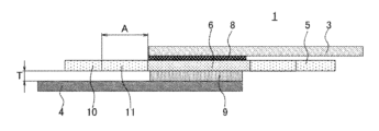
- FIG. 1 is a cross-sectional view schematically showing a secondary battery according to a first embodiment.
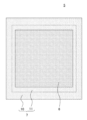
- FIG. 2 is a plan view showing the porous body.
- FIG. 3 is a schematic cross-sectional view showing a secondary battery according to the second embodiment.
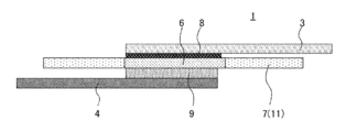
- FIG. 4 is a schematic cross-sectional view showing a secondary battery according to the third embodiment.
- FIG. 5 is a schematic cross-sectional view showing a secondary battery according to the fourth embodiment.
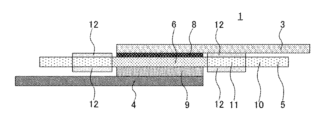
- FIG. 6 is a schematic cross-sectional view showing a secondary battery according to the fifth embodiment.
- FIG. 7 is a schematic cross-sectional view showing a secondary battery according to the sixth embodiment.
- FIG. 8 is a schematic cross-sectional view showing an example of a secondary battery according to the seventh embodiment.
- FIG. 9 is a schematic diagram showing another example of the secondary battery according to the seventh embodiment.
- a secondary battery 1 according to this embodiment is a secondary battery that is charged and discharged by the movement of lithium ions.
- This secondary battery 1 is a so-called all-solid-state battery.
- FIG. 1 is a cross-sectional view schematically showing a secondary battery 1 according to this embodiment.
- the secondary battery 1 has a structure in which a plurality of battery cells 2 are stacked.
- the secondary battery 1 is provided with a plurality of positive electrode current collector foils 4 and a plurality of negative electrode current collector foils 3.
- the plurality of positive electrode current collector foils 4 and the plurality of negative electrode current collector foils 3 are arranged alternately in the stacking direction.
- Each battery cell 2 is provided between adjacent positive electrode current collector foil 4 and negative electrode current collector foil 3.
- Each battery cell 2 is formed by a positive electrode 9, a negative electrode 8, and an electrolyte region 6.
- the electrolyte region 6 is a region provided in the sheet-like porous body 5, and is a region in which a solid electrolyte is supported. Electrolyte region 6 is sandwiched between positive electrode 9 and negative electrode 8. In other words, the positive electrode 9 and the negative electrode 8 are arranged above and below the porous body 5 so as to sandwich the electrolyte region 6 therebetween.
- the positive electrode 9 is provided between the electrolyte region 6 and the positive current collector foil 4, and the negative electrode 8 is provided between the electrolyte region 6 and the negative current collector foil 3.
- the external shapes of the positive electrode 9, negative electrode 8, and electrolyte region 6 when viewed along the stacking direction are generally the same. However, these do not need to match completely, and may be slightly different.
- the above-described secondary battery 1 generates power in a region where the positive electrode 9, the negative electrode 8, and the electrolyte region 6 overlap (hereinafter sometimes referred to as a power generation region). Specifically, during charging, lithium ions are conducted from the positive electrode 9 side to the negative electrode 8 side via the electrolyte region 6, and lithium ions are occluded on the negative electrode 8 side. Alternatively, lithium is deposited on the negative electrode 8 side. On the other hand, during discharging, lithium ions move from the negative electrode 8 side to the positive electrode 9 side, and lithium is inserted into the positive electrode 9.
- lithium dendrites may grow from the end of the negative electrode 8, as described above. If the lithium dendrite grows around the end of the electrolyte region 6, the positive electrode 9 and the negative electrode 8 will be short-circuited. Therefore, in this embodiment, the structure of the porous body 5 is devised.
- FIG. 2 is a plan view showing the porous body 5. As shown in FIGS. 1 and 2, each porous body 5 is provided with a non-supporting region 7 in addition to an electrolyte region 6.
- the electrolyte region 6 is a region in which a solid electrolyte is supported, and is provided at the center of each porous body 5.
- communication holes are provided in each porous body 5 so that lithium ions can conduct therethrough.
- the communication hole is a hole that penetrates each porous body 5.
- the solid electrolyte is supported in this communication hole.
- the non-supported region 7 is a region in which no solid electrolyte is supported.
- the non-supporting region 7 is provided on the outer periphery of each porous body 5 and surrounds the electrolyte region 6.
- the non-carrying area 7 is provided with a communicating area 10 and a non-communicating area 11.
- the communication region 10 is a region where both sides of the porous body 5 communicate in the stacking direction. Specifically, both sides of the porous body 5 communicate with each other via communicating holes.
- the non-communicating region 11 is a region where both sides of the porous body 5 are not connected in the stacking direction.
- the non-communicating region 11 is provided at a position surrounding the electrolyte region 6 and is continuous with the outer periphery of the electrolyte region 6.
- the non-communicating region 11 may be, for example, a region in which no communicating holes are present in the porous body 5 itself.
- the non-communicating region 11 may be a region in which the porous body 5 itself has communicating holes, but the communicating holes are closed.
- the non-communicating region 11 since the non-communicating region 11 is provided, it is possible to prevent lithium dendrite from growing around the end of the electrolyte region 6. If the non-communicating region 11 is not provided, that is, if the upper and lower parts of the porous body 5 are connected in the region outside the electrolyte region 6, the lithium dendrites will grow to penetrate the porous body 5. It's easy to do. Therefore, a short circuit between the negative electrode 8 and the positive electrode 9 due to the lithium dendrite may become a problem. However, in this embodiment, since the non-communicating region 11 is provided outside the electrolyte region 6, growth of lithium dendrites that would short-circuit the positive electrode 9 and the negative electrode 8 can be prevented.
- porous body 5 The material of the porous body 5 is not particularly limited as long as it can support the solid electrolyte.
- the porous body 5 can be manufactured using materials and methods as described below.
- a porous sheet having communicating holes is prepared.
- a porous sheet having communicating holes for example, a nonwoven fabric, a porous separator, a sheet in which communicating holes are formed by lithography processing, etc. can be used.
- the nonwoven fabric for example, polyester nonwoven fabric, polyethylene nonwoven fabric, cellulose fiber nonwoven fabric, etc. can be used.
- the communicating holes are closed around the electrolyte region 6 to form a non-communicating region 11.
- the communication holes can be closed by partially heating and melting the porous sheet.
- the communicating holes can be closed by filling the porous sheet with a resin material or the like so that the communicating holes are filled.
- the communicating holes can be closed by placing a covering material on the top or bottom surface of the porous sheet.
- the above is an example of a method for producing the porous body 5 using a porous sheet having communicating holes.
- the porous body 5 can also be produced using a porous sheet that originally does not have communicating pores (for example, a porous sheet that has closed pores).
- communicating holes are formed only in some regions (areas scheduled to become the electrolyte region 6 and the communication region 10) by lithography processing or the like.
- a slurry containing a solid electrolyte is applied to the area intended to become the electrolyte area 6 and dried. Thereby, electrolyte region 6 is formed. Even by using such a method, it is possible to obtain a porous body 5 having an electrolyte region 6, a communicating region 10, and a non-communicating region 11.
- the thickness of the porous body 5 is not particularly limited.
- the thickness of the porous body 5 in the electrolyte region 6 is 5 to 100 ⁇ m, preferably 20 to 60 ⁇ m.
- the solid electrolyte supported on the porous body 5 may be any solid electrolyte as long as it is solid and functions as an electrolyte.
- a sulfide solid electrolyte, an oxide solid electrolyte, etc. can be used as the solid electrolyte.
- the solid electrolyte is a sulfide solid electrolyte.
- the sulfide solid electrolyte include LPS-based (eg, argyrodite (Li 6 PS 5 Cl)) and LGPS-based (eg, Li 10 GeP 2 S 12 ) materials.
- the positive electrode 9 may be formed of a material that can release lithium ions during charging and occlude lithium ions during discharging.
- the positive electrode 9 is formed of, for example, a material containing a resin binder and a positive electrode active material dispersed in the resin binder.
- As the positive electrode active material for example, lithium metal composite oxide or the like can be used.
- lithium metal composite oxides include layered rock salt type compounds such as LiCoO 2 , LiMnO 2 , LiNiO 2 , LiVO 2 , and Li(Ni-Mn-Co)O 2 , LiMn 2 O 4 , and LiNi 0.5
- lithium metal composite oxides include layered rock salt type compounds such as LiCoO 2 , LiMnO 2 , LiNiO 2 , LiVO 2 , and Li(Ni-Mn-Co)O 2 , LiMn 2 O 4 , and LiNi 0.5
- spinel-type compounds such as Mn 1.5 O 4
- olivine-type compounds such as LiFePO 4 and LiMnPO 4
- Si-containing compounds such as Li 2 FeSiO 4 and Li 2 MnSiO 4 .
- Li 4 Ti 5 O 12 or the like can also be used.
- the thickness of the positive electrode 9 is not particularly limited, but is, for example, 10 to 500 ⁇ m, preferably 50 to 200 ⁇ m.
- the negative electrode 8 may be configured to occlude lithium (or deposit lithium) during charging and release lithium ions during discharging.
- the negative electrode 8 can be formed from a material containing a resin binder and a negative electrode active material dispersed in the resin binder.
- the negative electrode active material for example, lithium metal, silicon material (silicon), tin material, compounds containing silicon or tin (oxides, nitrides, alloys with other metals), and carbon materials (graphite, etc.) are used. be able to.
- the secondary battery 1 according to the present embodiment may be a so-called "all precipitation type" secondary battery.
- a fully-deposited secondary battery means that in a fully discharged state, the negative electrode side does not contain lithium as a negative electrode active material, and during charging, lithium ions move from the positive electrode side to the negative electrode side, and lithium metal is deposited on the negative electrode current collector foil 3.
- This is a battery configured to deposit.
- at least the lithium metal deposited on the negative electrode side during charging functions as the negative electrode 8, and therefore is included in the secondary battery 1 of the present invention.
- a negative electrode intermediate layer may be disposed between the solid electrolyte layer and the negative electrode current collector foil.
- the negative electrode intermediate layer is a layer interposed between the deposited lithium metal and the solid electrolyte layer.
- the negative electrode intermediate layer contains a lithium-reactive material. Examples of lithium-reactive materials include materials that can absorb and release lithium ions during charging, and metals that can be alloyed with lithium during charging.
- the material capable of intercalating and deintercalating lithium ions is not particularly limited, but carbon materials are preferred.
- carbon materials include carbon black (specifically, acetylene black, Ketjen black (registered trademark), furnace black, channel black, thermal lamp black, etc.), carbon nanotubes (CNT), graphite, hard carbon, etc. can be mentioned.
- carbon black is preferred, and at least one selected from the group consisting of acetylene black, Ketjen black (registered trademark), furnace black, channel black, and thermal lamp black is more preferred.
- metals that can be alloyed with lithium include In, Al, Si, Sn, Mg, Au, Ag, and Zn. Among them, In, Si, Sn, and Ag are preferred, and Ag is more preferred.
- the lithium-reactive materials may be used alone or in combination of two or more.
- a material capable of intercalating and deintercalating lithium ions and a metal capable of alloying with lithium thereby, sufficient strength and lithium ion conductivity of the negative electrode intermediate layer can be ensured.
- nanoparticles made of In, Si, Sn, and Ag together with carbon black More specifically, it is preferable to use nanoparticles made of In, Si, Sn, and Ag together with carbon black, and it is more preferable to use nanoparticles made of Ag and carbon black together.
- the compounding ratio (mass ratio) of these is not particularly limited, but the material capable of intercalating and deintercalating lithium ions: lithium and alloy
- the ratio of metals that can be converted is preferably 10:1 to 1:1, more preferably 5:1 to 2:1.
- the content of the lithium-reactive material in the negative electrode intermediate layer (if two or more materials are used together, it refers to the total content, hereinafter the same) is not particularly limited, but within the range of 50 to 100% by mass. It is preferably within the range of 70 to 100% by mass, even more preferably within the range of 85 to 99% by mass, and particularly preferably within the range of 90 to 100% by mass.
- the negative electrode intermediate layer may be made of only a lithium-reactive material, as long as a self-supporting film can be produced using only the lithium-reactive material, but it may also contain a binder if necessary.
- the type of binder is not particularly limited, and any binder known in the technical field can be used as appropriate. Examples include polyvinylidene fluoride (PVDF) (including compounds in which hydrogen atoms are replaced with other halogen elements), polytetrafluoroethylene (PTFE), styrene-butadiene rubber (SBR), and carboxymethyl cellulose.
- the content of the binder in the negative electrode intermediate layer is not particularly limited, but is preferably in the range of 1 to 15% by mass, more preferably in the range of 5 to 10% by mass. If the binder content is 1% by mass or more, a negative electrode intermediate layer having sufficient strength can be formed. When the content of the binder is 15% by mass or less, a negative electrode intermediate layer having sufficient lithium ion conductivity can be formed.
- the thickness of the negative electrode intermediate layer is not particularly limited, but is preferably 1 to 50 ⁇ m, more preferably 5 to 40 ⁇ m, and even more preferably 10 to 30 ⁇ m. When the thickness of the negative electrode intermediate layer is 1 ⁇ m or more, the functions of the negative electrode intermediate layer can be fully exhibited. When the thickness of the negative electrode intermediate layer is 50 ⁇ m or less, a decrease in energy density can be suppressed.
- the positive electrode current collector foil 4 and the negative electrode current collector foil 3 are provided to electrically connect the secondary battery 1 to an external device. As shown in FIG. 1, the positive electrode current collector foil 4 and the negative electrode current collector foil 3 each extend so as to protrude laterally from the power generation area.
- the positive electrode current collector foil 4 and the negative electrode current collector foil 3 are each formed of a conductive thin film.
- the positive electrode current collector foil 4 for example, aluminum foil can be used.
- the method for manufacturing the secondary battery 1 according to this embodiment is not particularly limited. Below, a specific method for manufacturing the secondary battery 1 according to the present embodiment will be described by giving an example.
- Predetermined amounts of a positive electrode active material, a sulfide solid electrolyte, a conductive aid, a binder, and xylene are weighed and mixed to prepare a slurry.
- the prepared slurry is applied to a carbon-coated aluminum foil (positive electrode current collector foil 4).
- the slurry is applied to both sides in a predetermined area. After application, dry.
- a positive electrode current collector foil 4 having a positive electrode 9 formed thereon with a thickness of 200 ⁇ m (100 ⁇ m on one side) is obtained.
- Predetermined amounts of the sulfide solid electrolyte, binder, and xylene are weighed and mixed to prepare a slurry.
- the prepared slurry is directly applied to a 40 ⁇ m porous sheet (having communicating pores) and dried. This causes the porous sheet to support the solid electrolyte, forming the electrolyte region 6.
- a covering material is placed in a predetermined area to form a non-communicating area 11. As a result, a porous body 5 is obtained.
- Predetermined amounts of a negative electrode active material, a binder, and NMP (N-methylpyrrolidone) are weighed and mixed to prepare a slurry.
- the prepared slurry is applied to SUS foil (negative electrode current collector foil 3).
- the slurry is applied to both sides in a predetermined area. After application, dry.
- a negative electrode current collector foil 3 on which a negative electrode 8 having a thickness of 100 ⁇ m (50 ⁇ m on one side) is formed is obtained.
- the secondary battery 1 has a plurality of battery cells 2 was explained.
- the secondary battery 1 does not necessarily need to have a plurality of battery cells 2, and the secondary battery 1 may be configured by a single battery cell 2.
- the first embodiment has been described above.
- the configuration and effects of the secondary battery 1 according to this embodiment are summarized as follows.
- the secondary battery 1 includes a porous body 5 having an electrolyte region 6 supporting a solid electrolyte and a non-supporting region 7 not supporting a solid electrolyte; A positive electrode 9 and a negative electrode 8 are arranged above and below 5.
- the non-supporting region 7 has a non-communicating region 11 in which both sides of the porous body 5 in the stacking direction are not communicating with each other.
- the non-communicating region 11 is continuous with the outer periphery of the electrolyte region 6 and is provided at a position surrounding the electrolyte region 6.
- FIG. 3 is a schematic cross-sectional view showing the main parts of the secondary battery 1 according to the second embodiment.
- the width of the non-communicating region 11 (A in FIG. 3) is greater than or equal to the thickness of the positive electrode 9 (T in FIG. 3).
- Vibrations and the like may be applied to the secondary battery 1.
- the negative electrode current collector foil 3 and the porous body 5 may bend toward the positive electrode 9 side, and the negative electrode current collector foil 3 may approach the positive electrode 9.
- the negative electrode current collector foil 3 approaches the positive electrode 9 short circuits due to lithium dendrites are likely to occur.
- the width of the non-communicating region 11 is greater than or equal to the thickness of the positive electrode 9, even if the negative electrode current collector foil 3 and the porous body 5 are bent, the positive electrode 9 and the negative electrode current collector foil 3 are , still separated by a non-communicating region 11. Therefore, even if the negative electrode current collector foil 3 and the porous body 5 are bent, short circuits due to lithium dendrites are unlikely to occur.
- FIG. 4 is a schematic cross-sectional view showing a secondary battery 1 according to the third embodiment. As shown in FIG. 4, in this embodiment, the entire non-supporting region 7 of the porous body 5 is a non-communicating region 11. That is, the communication area 10 does not exist in the non-carrying area 7.
- the entire non-supporting region 7 is the non-communicating region 11
- growth of lithium dendrites that wrap around the electrolyte region 6 is more reliably prevented.
- FIG. 5 is a schematic cross-sectional view showing a secondary battery 1 according to the fourth embodiment.
- the thickness of the porous body 5 is designed. Specifically, the thickness of the porous body 5 in the non-supporting region 7 (T2 in the figure) is greater than the thickness of the porous body 5 in the electrolyte region 6 (T1 in the figure).
- the thickness of the structure (that is, the porous body 5) separating the positive electrode side and the negative electrode side is increased in the area around the electrolyte region 6. Therefore, the growth of lithium dendrites is likely to be hindered. Therefore, short circuits can be prevented more reliably.
- FIG. 6 is a schematic cross-sectional view showing a secondary battery 1 according to the fifth embodiment.
- a covering material 12 is provided on the upper and lower surfaces of the porous body 5 in the non-communicating region 11. That is, in the non-communicating region 11, the communicating holes of the porous body 5 are closed by the covering material 12.
- the covering material 12 is not particularly limited, but for example, a tape material (such as a polyimide film), a coating agent, an inorganic particle material, etc. can be used.
- the thickness of the porous body 5 is substantially increased due to the covering material 12. Therefore, similarly to the fourth embodiment, the growth of lithium dendrites is likely to be hindered. Therefore, short circuits can be prevented more reliably.
- the covering material 12 is provided on both the upper and lower surfaces of the porous body 5.
- the covering material 12 may be provided only on one side of the porous body 5. In this case, since lithium dendrites grow from the negative electrode 8 side, it is preferable that the covering material 12 is provided on the surface of the porous body 5 on the negative electrode 8 side.
- FIG. 7 is a schematic cross-sectional view showing a secondary battery 1 according to the sixth embodiment. As shown in FIG. 7, in this embodiment, the covering material 12 is arranged to cover the boundary between the electrolyte region 6 and the non-supporting region 7.
- the binding force of the solid electrolyte in the porous body 5 is often weak.
- the solid electrolyte may fall off from the porous body 5, and a space may be formed that penetrates the porous body 5 from above and below.
- lithium dendrites grow vertically through the porous body 5, and there is a possibility that the positive electrode 9 and the negative electrode 8 will be short-circuited.
- the boundary between the electrolyte region 6 and the non-supporting region 7 is protected by the covering material 12. Therefore, the solid electrolyte can be prevented from falling off, and short circuits can be more reliably prevented.
- FIG. 8 is a schematic cross-sectional view showing an example of the secondary battery 1 according to the present embodiment.
- one porous body 5 is commonly used between two adjacent battery cells 2. Specifically, each porous body 5 is bent so as to wrap around the positive electrode current collector foil 4 and the positive electrode 9 (see folded portion 14 in the figure). The lower part of each porous body 5 is sandwiched between the positive electrode 9 and the negative electrode 8 in the lower battery cell 2, and the upper part is sandwiched between the positive electrode 9 and the negative electrode 8 in the upper battery cell 2. I'm caught in the middle. Further, in each porous body 5, the outer circumferential portion of the upper portion overlaps the outer circumferential portion of the lower portion.
- each porous body 5 is adhered to the positive electrode current collector foil 4 .
- the side surfaces of the positive electrode 9 are entirely covered with each porous body 5.
- the negative electrode current collector foil 3 and the positive electrode current collector foil 4 are separated by the porous body 5. Therefore, even if the negative current collector foil 3 or the positive current collector foil 4 is bent, they do not come into contact with each other. Therefore, short circuit due to contact between the negative electrode current collector foil 3 and the positive electrode current collector foil 4 can be prevented. Furthermore, it is also possible to prevent lithium dendrites from growing around the edges of the porous body 5.
- the porous body 5 is configured to cover the side surface of the positive electrode 9, but the porous body 5 is bent so as to cover the side surface of the negative electrode 8 instead of the positive electrode 9. Good too.
- FIG. 9 is a schematic diagram showing another example of the secondary battery 1 according to the present embodiment.
- the porous bodies 5 in adjacent battery cells 2 are bonded to each other by thermal bonding at the outer peripheral portions (see thermal bonding portion 15 in FIG. 9).
- the outer peripheries of the porous bodies 5 of the upper and lower battery cells 2 are joined by heat fusion at portions other than the portions where the negative electrode current collector foil 3 and the positive electrode current collector foil 4 are provided.
Abstract
二次電池は.多孔体と、正極及び負極とを有ずる。多孔体は、固体電解質が担持された電解質領域と、固体電解質が担持されていない非担持領域とを有する。非担持領域は、積層方向における多孔体の両側が連通していない非連通領域を有する。非連通領域は、電解質領域の外周部に連続しており、電解質領域を取り囲む位置に設けられている。
Description
本発明は、二次電池に関する。
電解質層を挟むように正極及び負極が設けられ、正極と負極との間でリチウムイオンが移動することにより充放電が行われる二次電池が知られている。そのような二次電池として、固体電解質がシート状の多孔体に担持された構成を有するものが知られている。多孔体に固体電解質を担持させることにより、薄くても自立した電解質層を得ることができる。
上記に関連する技術が、例えば特許文献1(JP2021−533542A)に開示されている。特許文献1には、第1保護層、フィルム状の第1固体電解質材料、多孔性基材、フィルム状の第2固体電解質材料、第2保護層を順次に積層して積層構造体を用意する段階と、この積層構造体を加圧して第1固体電解質材料及び第2固体電解質材料を多孔性基材の内部に押し込み、多孔性基材の気孔を固体電解質材料で充填させる段階と、第1保護層及び第2保護層を除去する段階と、を含み、加圧はロールプレス方法で行われる、全固体電池用固体電解質膜の製造方法が開示されている。この固体電解質膜は、不織布などの多孔質の高分子材料と固体電解質材料とが複合化しているため、優れた強度を有しながらも70μm以下の薄膜型で製造することができ、電池のエネルギー密度の向上に有利である。
ところで、リチウムイオンが充放電に使用される二次電池においては、充電時に、負極からリチウムデンドライトが成長する場合がある。リチウムデンドライトが電解質層の端部を回りこむように成長すると、正極と負極とが短絡してしまう。この問題は、固体電解質が多孔体に担持された構成を有する二次電池においても生じ得る。
そこで、本発明の目的は、固体電解質が多孔体に担持された構成を有する二次電池において、リチウムデンドライトによる短絡を防止することのできる技術を提供することにある。
以下に、図面を参照しつつ、本発明の実施形態について説明する。
第1の実施形態
本実施形態に係る二次電池1は、リチウムイオンの移動によって充放電が行われる二次電池である。この二次電池1は、いわゆる全固体電池である。
本実施形態に係る二次電池1は、リチウムイオンの移動によって充放電が行われる二次電池である。この二次電池1は、いわゆる全固体電池である。
(概略)
図1は、本実施形態に係る二次電池1を概略的に示す断面図である。図1に示されるように、二次電池1は、複数の電池セル2が積層された構成を有している。具体的には、二次電池1には、複数の正極集電箔4と、複数の負極集電箔3とが設けられている。複数の正極集電箔4と、複数の負極集電箔3とは、積層方向において交互になるように配置されている。
図1は、本実施形態に係る二次電池1を概略的に示す断面図である。図1に示されるように、二次電池1は、複数の電池セル2が積層された構成を有している。具体的には、二次電池1には、複数の正極集電箔4と、複数の負極集電箔3とが設けられている。複数の正極集電箔4と、複数の負極集電箔3とは、積層方向において交互になるように配置されている。
各電池セル2は、隣り合う正極集電箔4と負極集電箔3との間に設けられている。各電池セル2は、正極9と、負極8と、電解質領域6とによって形成されている。電解質領域6は、シート状の多孔体5に設けられた領域であり、固体電解質が担持された領域である。電解質領域6は、正極9と負極8とによって挟まれている。言い換えれば、正極9及び負極8は、電解質領域6を挟むように、多孔体5の上下に配置されている。正極9は、電解質領域6と正極集電箔4との間に設けられており、負極8は、電解質領域6と負極集電箔3との間に設けられている。
積層方向に沿って見た場合における正極9、負極8、及び電解質領域6の外形は、概ね一致している。ただし、これらは完全に一致している必要はなく、多少であれば、ずれていてもよい。
上述の二次電池1は、正極9と、負極8と、電解質領域6とが重なった領域(以下、発電領域という場合がある)において発電する。具体的には、充電時には、正極9側から電解質領域6を介して負極8側にリチウムイオンが伝導し、負極8側においてリチウムイオンが吸蔵される。あるいは、負極8側にリチウムが析出する。一方、放電時には、負極8側からリチウムイオンが正極9側に移動し、正極9にリチウムが吸蔵される。
このような二次電池1においては、既述のように、負極8の端部からリチウムデンドライトが成長する可能性がある。リチウムデンドライトが電解質領域6の端部を回りこむように成長すると、正極9と負極8とが短絡してしまう。そこで、本実施形態においては、多孔体5の構成が工夫されている。
図2は、多孔体5を示す平面図である。図1及び図2に示されるように、各多孔体5には、電解質領域6に加えて、非担持領域7が設けられている。
電解質領域6は、既述の通り、固体電解質が担持された領域であり、各多孔体5における中央部に設けられている。電解質領域6においては、リチウムイオンが伝導可能となるように、各多孔体5に、連通孔が設けられている。連通孔は、各多孔体5を貫通するような孔である。固体電解質は、この連通孔に担持されている。
一方、非担持領域7は、固体電解質が担持されていない領域である。非担持領域7は、各多孔体5の外周部に設けられており、電解質領域6を取り囲んでいる。
非担持領域7には、連通領域10と非連通領域11とが設けられている。
連通領域10は、積層方向において多孔体5の両側が連通している領域である。具体的には、多孔体5の両側は、連通孔を介して連通している。
一方、非連通領域11は、積層方向において多孔体5の両側が連通していない領域である。非連通領域11は、電解質領域6を取り囲む位置に設けられており、電解質領域6の外周部に連続している。非連通領域11は、例えば、多孔体5自体に連通孔が存在しない領域であり得る。あるいは、非連通領域11は、多孔体5自体には連通孔が存在するものの、その連通孔が塞がれた領域であってもよい。
上述のような構成によれば、非連通領域11が設けられているため、電解質領域6の端部を回りこむようなリチウムデンドライトの成長を防止することができる。仮に、非連通領域11が設けられていなかった場合、すなわち、電解質領域6の外側の領域において多孔体5の上下が連通している場合には、リチウムデンドライトが多孔体5を貫通するように成長しやすい。そのため、リチウムデンドライトによる負極8と正極9との短絡が問題となり得る。しかしながら、本実施形態においては、電解質領域6の外側には、非連通領域11が設けられているから、正極9と負極8とを短絡させるようなリチウムデンドライトの成長を防ぐことができる。
続いて、本実施形態に係る二次電池1における各部の詳細について説明する。
(多孔体)
多孔体5の材質は、固体電解質を担持することができるようなものであればよく、特に限定されない。例えば、多孔体5は、以下に説明するような材料及び方法により、作製することができる。
多孔体5の材質は、固体電解質を担持することができるようなものであればよく、特に限定されない。例えば、多孔体5は、以下に説明するような材料及び方法により、作製することができる。
まず、連通孔を有する多孔質シートを準備する。連通孔を有する多孔質シートとしては、例えば、不織布、多孔質セパレータ、及びリソグラフィ加工により連通孔を形成したシート等を用いることができる。不織布としては、例えば、ポリエステル不織布、ポリエチレン不織布、およびセルロース繊維製の不織布等を用いることができる。
続いて、電解質領域6を形成する予定の領域に、固体電解質を有するスラリーを塗布し、乾燥させる。これにより、電解質領域6を形成する。
加えて、電解質領域6の周囲において連通孔を塞ぎ、非連通領域11を形成する。例えば、多孔質シートとして熱により溶融するような材料を使用した場合には、多孔質シートを部分的に加熱して溶融させることにより、連通孔を塞ぐことができる。あるいは、連通孔が埋まるように樹脂材料等を多孔質シートに充填することにより、連通孔を塞ぐこともできる。あるいは、後述する実施形態においても説明するように、多孔質シートの上面又は下面に被覆材を配置することによって、連通孔を塞ぐこともできる。
以上が、連通孔を有する多孔質シートを利用した場合の多孔体5の作製方法の一例である。
一方で、もともと連通孔を有さない多孔質シート(例えば、クローズドポアを有する多孔質シート)を用いて、多孔体5を作製することもできる。この場合には、まず、リソグラフィ加工等によって、一部の領域(電解質領域6及び連通領域10となる予定の領域)にのみ、連通孔を形成する。次いで、電解質領域6となる予定の領域に、固体電解質を含むスラリーを塗布し、乾燥させる。これにより、電解質領域6を形成する。このような方法を用いても、電解質領域6、連通領域10、及び非連通領域11を有する多孔体5を得ることもできる。
なお、多孔体5の厚みは特に限定されるものではない。例えば、多孔体5の厚みは、電解質領域6において、5~100μm、好ましくは20~60μmである。
多孔体5に担持される固体電解質は、固体であり電解質として機能するものであればよい。例えば、固体電解質として、硫化物固体電解質及び酸化物固体電解質などを用いることができる。好ましくは、固体電解質は、硫化物固体電解質である。硫化物固体電解質としては、例えばLPS系(例えばアルジロダイト(Li6PS5Cl))、およびLGPS系(例えばLi10GeP2S12)の材料が挙げられる。
(正極)
正極9は、充電時にリチウムイオンを放出し、放電時にリチウムイオンを吸蔵することができる材料により形成されていればよい。正極9は、例えば、樹脂バインダーと、樹脂バインダー中に分散した正極活物質とを含む材料により形成される。正極活物質としては、例えば、リチウム金属複合酸化物などを用いることができる。リチウム金属複合酸化物としては、例えば、LiCoO2、LiMnO2、LiNiO2、LiVO2、及びLi(Ni−Mn−Co)O2等の層状岩塩型化合物、LiMn2O4、及びLiNi0.5Mn1.5O4等のスピネル型化合物、LiFePO4、及びLiMnPO4等のオリビン型化合物、あるいは、Li2FeSiO4、及びLi2MnSiO4等のSi含有化合物等が挙げられる。また、Li4Ti5O12なども用いることができる。
正極9は、充電時にリチウムイオンを放出し、放電時にリチウムイオンを吸蔵することができる材料により形成されていればよい。正極9は、例えば、樹脂バインダーと、樹脂バインダー中に分散した正極活物質とを含む材料により形成される。正極活物質としては、例えば、リチウム金属複合酸化物などを用いることができる。リチウム金属複合酸化物としては、例えば、LiCoO2、LiMnO2、LiNiO2、LiVO2、及びLi(Ni−Mn−Co)O2等の層状岩塩型化合物、LiMn2O4、及びLiNi0.5Mn1.5O4等のスピネル型化合物、LiFePO4、及びLiMnPO4等のオリビン型化合物、あるいは、Li2FeSiO4、及びLi2MnSiO4等のSi含有化合物等が挙げられる。また、Li4Ti5O12なども用いることができる。
正極9の厚みは、特に限定されるものではないが、例えば10~500μm、好ましくは50~200μmである。
(負極)
負極8は、充電時にリチウムを吸蔵し(あるいはリチウムを析出させ)、放電時にリチウムイオンを放出することができるように構成されていればよい。例えば、負極8は、樹脂バインダーと、樹脂バインダーに分散させた負極活物質とを含む材料により、形成することができる。負極活物質としては、例えば、リチウム金属、ケイ素材料(シリコン)、スズ材料、ケイ素やスズを含む化合物(酸化物、窒化物、他の金属との合金)、および炭素材料(グラファイト等)を用いることができる。
負極8は、充電時にリチウムを吸蔵し(あるいはリチウムを析出させ)、放電時にリチウムイオンを放出することができるように構成されていればよい。例えば、負極8は、樹脂バインダーと、樹脂バインダーに分散させた負極活物質とを含む材料により、形成することができる。負極活物質としては、例えば、リチウム金属、ケイ素材料(シリコン)、スズ材料、ケイ素やスズを含む化合物(酸化物、窒化物、他の金属との合金)、および炭素材料(グラファイト等)を用いることができる。
なお、本実施形態に係る二次電池1は、いわゆる「全析出型」の二次電池であってもよい。全析出型の二次電池とは、完全放電状態では負極側に負極活物質としてのリチウムが含まれず、充電時に正極側から負極側にリチウムイオンが移動し、負極集電箔3上にリチウム金属が析出するように構成された電池である。このような電池においては、少なくとも、充電時に負極側に析出するリチウム金属が、負極8として機能するから、本発明の二次電池1に包含される。
また、全析出型の二次電池1においては、固体電解質層と負極集電箔の間に負極中間層が配置されてもよい。負極中間層は、析出するリチウム金属と固体電解質層との間に介在する層である。負極中間層は、リチウム反応性材料を含有する。リチウム反応性材料としては、充電時にリチウムイオンを吸蔵放出可能な材料や、充電時にリチウムと合金化可能な金属が挙げられる。
リチウムイオンを吸蔵放出可能な材料としては、特に制限されないが、炭素材料が好ましい。炭素材料の具体例としては、カーボンブラック(具体的には、アセチレンブラック、ケッチェンブラック(登録商標)、ファーネスブラック、チャンネルブラック、サーマルランプブラック等)、カーボンナノチューブ(CNT)、グラファイト、ハードカーボン等が挙げられる。中でも、カーボンブラックが好ましく、アセチレンブラック、ケッチェンブラック(登録商標)、ファーネスブラック、チャンネルブラックおよびサーマルランプブラックからなる群から選択させる少なくとも1種であることがより好ましい。
リチウムと合金化可能な金属としては、例えば、In、Al、Si、Sn、Mg、Au、Ag、Znなどが挙げられる。中でも、In、Si、Sn、Agが好ましく、Agがより好ましい。
リチウム反応性材料は、1種を単独で使用しても、2種以上を併用しても構わない。2種以上を併用する形態として、リチウムイオンを吸蔵放出可能な材料と、リチウムと合金化可能な金属とを併用することも好ましい。これにより、負極中間層の充分な強度やリチウムイオン伝導性を確保することができる。より詳細には、In、Si、Sn、Agからなるナノ粒子と、カーボンブラックとを併用することが好ましく、Agからなるナノ粒子と、カーボンブラックとを併用することがより好ましい。リチウムイオンを吸蔵放出可能な材料と、リチウムと合金化可能な金属とを併用する場合のこれらの配合比(質量比)は、特に制限されないが、リチウムイオンを吸蔵放出可能な材料:リチウムと合金化可能な金属が好ましくは10:1~1:1であり、より好ましくは5:1~2:1である。
負極中間層におけるリチウム反応性材料の含有量(2種以上の材料を併用する場合はそれらの含有量の合計を指す、以下同様)は、特に制限されないが、50~100質量%の範囲内であることが好ましく、70~100質量%の範囲内であることがより好ましく、85~99質量%の範囲内であることがさらに好ましく、90~100質量%の範囲内であることが特に好ましい。
負極中間層は、リチウム反応性材料のみで自立膜を作製可能であれば、リチウム反応性材料のみからなるものであってもよいが、必要に応じてバインダを含んでもよい。バインダの種類は、特に制限されず、本技術分野で公知のものを適宜採用することができる。一例としては、ポリフッ化ビニリデン(PVDF)(水素原子が他のハロゲン元素にて置換された化合物を含む)、ポリテトラフルオロエチレン(PTFE)、スチレン・ブタジエンゴム(SBR)、カルボキシメチルセルロースが挙げられる。
負極中間層におけるバインダの含有量は、特に制限されないが、1~15質量%の範囲内であることが好ましく、5~10質量%の範囲内であることがより好ましい。バインダの含有量が1質量%以上であれば充分な強度を有する負極中間層を形成できる。バインダの含有量が15質量%以下であれば、充分なリチウムイオン伝導性を有する負極中間層を形成できる。
負極中間層の厚さは、特に制限されないが、1~50μmであることが好ましく、5~40μmであることがより好ましく、10~30μmであることがさらに好ましい。負極中間層の厚さが1μm以上であると、負極中間層が有する機能を充分に発揮できる。負極中間層の厚さが50μm以下であると、エネルギー密度の低下を抑制できる。
(正極集電箔及び負極集電箔)
正極集電箔4及び負極集電箔3は、二次電池1を外部の装置の電気的に接続するために設けられている。図1に示されるように、正極集電箔4及び負極集電箔3は、それぞれ、発電領域から側方に向かって突き出るように延びている。正極集電箔4及び負極集電箔3は、それぞれ、導電性の薄膜により形成される。正極集電箔4としては、例えばアルミニウム箔などを用いることができる。負極集電箔3としては、例えば、ステンレス薄膜、及び銅薄膜などを用いることができる。
正極集電箔4及び負極集電箔3は、二次電池1を外部の装置の電気的に接続するために設けられている。図1に示されるように、正極集電箔4及び負極集電箔3は、それぞれ、発電領域から側方に向かって突き出るように延びている。正極集電箔4及び負極集電箔3は、それぞれ、導電性の薄膜により形成される。正極集電箔4としては、例えばアルミニウム箔などを用いることができる。負極集電箔3としては、例えば、ステンレス薄膜、及び銅薄膜などを用いることができる。
(製造例)
本実施形態に係る二次電池1の製造方法は、特に限定されない。以下に、本実施形態に係る二次電池1の具体的な製造方法について、一例を挙げて説明する。
本実施形態に係る二次電池1の製造方法は、特に限定されない。以下に、本実施形態に係る二次電池1の具体的な製造方法について、一例を挙げて説明する。
[正極の作製]
正極活物質、硫化物固体電解質、導電助剤、バインダー、及びキシレンを所定量秤量して混合し、スラリーを調製する。調製したスラリーを、カーボンコートされたアルミニウム箔(正極集電箔4)に塗布する。スラリーは、所定領域における両面に塗布される。塗布後、乾燥を行う。これにより、厚み200μm(片面100μm)の正極9が形成された正極集電箔4を得る。
正極活物質、硫化物固体電解質、導電助剤、バインダー、及びキシレンを所定量秤量して混合し、スラリーを調製する。調製したスラリーを、カーボンコートされたアルミニウム箔(正極集電箔4)に塗布する。スラリーは、所定領域における両面に塗布される。塗布後、乾燥を行う。これにより、厚み200μm(片面100μm)の正極9が形成された正極集電箔4を得る。
[固体電解質が担持された多孔体の作製]
硫化物固体電解質、バインダー、及びキシレンを所定量秤量して混合し、スラリーを調製する。調製したスラリーを、40μmの多孔質シート(連通孔を有するもの)に直接に塗工し、乾燥させる。これにより、多孔質シートに固体電解質を担持させ、電解質領域6を形成する。更に、所定の領域に被覆材を配置し、非連通領域11を形成する。これにより、多孔体5を得る。
硫化物固体電解質、バインダー、及びキシレンを所定量秤量して混合し、スラリーを調製する。調製したスラリーを、40μmの多孔質シート(連通孔を有するもの)に直接に塗工し、乾燥させる。これにより、多孔質シートに固体電解質を担持させ、電解質領域6を形成する。更に、所定の領域に被覆材を配置し、非連通領域11を形成する。これにより、多孔体5を得る。
[負極の作製]
負極活物質、バインダー、NMP(N−メチルピロリドン)を所定量秤量して混合し、スラリーを調製する。調製したスラリーを、SUS箔(負極集電箔3)に塗布する。スラリーは、所定領域における両面に塗布される。塗布後、乾燥を行う。これにより、厚み100μm(片面50μm)の負極8が形成された負極集電箔3を得る。
負極活物質、バインダー、NMP(N−メチルピロリドン)を所定量秤量して混合し、スラリーを調製する。調製したスラリーを、SUS箔(負極集電箔3)に塗布する。スラリーは、所定領域における両面に塗布される。塗布後、乾燥を行う。これにより、厚み100μm(片面50μm)の負極8が形成された負極集電箔3を得る。
[正極/固体電解質/負極積層体の作製]
上述の手順により作成した正極9が形成された正極集電箔4の上下に、多孔体5、及び負極8が形成された負極集電箔3を配置する。そして、ロールプレスを行うことにより、これらが積層された積層体を得る。
上述の手順により作成した正極9が形成された正極集電箔4の上下に、多孔体5、及び負極8が形成された負極集電箔3を配置する。そして、ロールプレスを行うことにより、これらが積層された積層体を得る。
[セルの積層体の作製]
更に、得られた積層体を複数枚積層する。その後、正極集電箔4にアルミニウムタブを、負極集電箔3にNiめっき銅タブを、それぞれ超音波溶接機により接合する。最後に、積層体を、アルミラミネートフィルムに入れて真空封止する。これにより、複数の電池セル2が積層された構成を有する二次電池1が得られる。
更に、得られた積層体を複数枚積層する。その後、正極集電箔4にアルミニウムタブを、負極集電箔3にNiめっき銅タブを、それぞれ超音波溶接機により接合する。最後に、積層体を、アルミラミネートフィルムに入れて真空封止する。これにより、複数の電池セル2が積層された構成を有する二次電池1が得られる。
なお、上述の例では、二次電池1が複数の電池セル2を有している場合について説明した。ただし、二次電池1は、必ずしも複数の電池セル2を有している必要はなく、単一の電池セル2により二次電池1が構成されていてもよい。
以上、第1の実施形態について説明した。本実施形態に係る二次電池1の構成と作用効果を要約すると、以下のとおりである。
本実施形態に係る二次電池1は、固体電解質が担持された電解質領域6と、固体電解質が担持されていない非担持領域7とを有する多孔体5と、電解質領域6を挟むように多孔体5の上下に配置された、正極9及び負極8とを備える。非担持領域7は、積層方向における多孔体5の両側が連通していない非連通領域11を有している。非連通領域11は、電解質領域6の外周部に連続しており、電解質領域6を取り囲む位置に設けられている。このような構成によれば、電解質領域6を取り囲む領域が非連通領域11となっているため、電解質領域6の端部を回りこむようなリチウムデンドライトの成長が抑制される。よって、正極9と負極8との短絡を防止することができる。
第2の実施形態
続いて、第2の実施形態について説明する。なお、第1の実施形態と同様の構成を採用することができる点については、説明を省略する。
続いて、第2の実施形態について説明する。なお、第1の実施形態と同様の構成を採用することができる点については、説明を省略する。
図3は、第2の実施形態に係る二次電池1の主要部を示す概略断面図である。本実施形態においては、非連通領域11の幅(図3中、A)が、正極9の厚み(図3中、T)以上になっている。
二次電池1には、振動などが加わる場合がある。その結果、負極集電箔3及び多孔体5が正極9側に折れ曲がり、負極集電箔3が正極9に近づく場合がある。負極集電箔3が正極9に近づくと、リチウムデンドライトによる短絡が生じやすくなる。
しかしながら、本実施形態においては、非連通領域11の幅が、正極9の厚み以上であるから、負極集電箔3及び多孔体5が折れ曲がったとしても、正極9と負極集電箔3とは、依然として非連通領域11により隔てられる。従って、負極集電箔3及び多孔体5が折れ曲がったとしても、リチウムデンドライトによる短絡は生じ難い。
第3の実施形態
続いて、第3の実施形態について説明する。第1の実施形態と同様の構成を採用することができる点については、説明を省略する。
続いて、第3の実施形態について説明する。第1の実施形態と同様の構成を採用することができる点については、説明を省略する。
図4は、第3の実施形態に係る二次電池1を示す概略断面図である。図4に示されるように、本実施形態においては、多孔体5において、非担持領域7の全域が、非連通領域11となっている。すなわち、非担持領域7に連通領域10は存在しない。
本実施形態によれば、非担持領域7の全域が非連通領域11であるため、電解質領域6を回り込むようなリチウムデンドライトの成長が、より確実に防止される。
第4の実施形態
続いて、第4の実施形態について説明する。既述の実施形態と同様の構成を採用することができる点については、説明を省略する。
続いて、第4の実施形態について説明する。既述の実施形態と同様の構成を採用することができる点については、説明を省略する。
図5は、第4の実施形態に係る二次電池1を示す概略断面図である。図5に示されるように、本実施形態においては、多孔体5の厚みが工夫されている。具体的には、電解質領域6における多孔体5の厚み(図中、T1)よりも、非担持領域7における多孔体5の厚み(図中、T2)の方が大きい。
本実施形態によれば、電解質領域6の周囲の領域において、正極側と負極側とを隔てる構造(すなわち多孔体5)の厚みが大きくなっている。そのため、リチウムデンドライトの成長が妨げられやすい。従って、より確実に短絡を防止できる。
第5の実施形態
続いて、第5の実施形態について説明する。なお、既述の実施形態と同様の構成を採用することができる点については、説明を省略する。
続いて、第5の実施形態について説明する。なお、既述の実施形態と同様の構成を採用することができる点については、説明を省略する。
図6は、第5の実施形態に係る二次電池1を示す概略断面図である。図6に示されるように、非連通領域11における多孔体5の上面上及び下面上に、被覆材12が設けられている。すなわち、非連通領域11においては、被覆材12によって、多孔体5の連通孔が塞がれている。被覆材12としては、特に限定されるものではないが、例えばテープ材料(ポリイミドフィルムなど)、コーティング剤、及び無機粒子材などを用いることができる。
本実施形態によれば、電解質領域6の外側の領域においては、被覆材12により、多孔体5の厚みが実質的に厚くなっている。従って、第4の実施形態と同様に、リチウムデンドライトの成長が妨げられやすい。そのため、より確実に短絡を防止できる。
なお、図6に示した例では、多孔体5の上面及び下面の双方に被覆材12が設けられている。ただし、被覆材12は、多孔体5の片面側にのみ設けられていてもよい。この場合、リチウムデンドライトは負極8側から成長するため、多孔体5における負極8側の面に被覆材12が設けられていることが好ましい。
第6の実施形態
続いて、第6の実施形態について説明する。本実施形態は、第5の実施形態の変形例である。第5の実施形態と同様の構成を採用することができる点については、説明を省略する。
続いて、第6の実施形態について説明する。本実施形態は、第5の実施形態の変形例である。第5の実施形態と同様の構成を採用することができる点については、説明を省略する。
図7は、第6の実施形態に係る二次電池1を示す概略断面図である。図7に示されるように、本実施形態においては、被覆材12が、電解質領域6と非担持領域7との境界を覆うように配置されている。
電解質領域6の端部では、多孔体5における固体電解質の結着力が弱くなることが多い。その結果、多孔体5から固体電解質が脱落し、多孔体5に上下を貫通するような空間が形成されてしまう場合がある。これにより、リチウムデンドライトが多孔体5を上下に貫通するように成長し、正極9と負極8とが短絡してしまう可能性がある。
しかしながら、本実施形態によれば、電解質領域6と非担持領域7との境界が被覆材12により保護されている。従って、固体電解質の脱落を防止でき、短絡をより確実に防ぐことができる。
第7の実施形態
続いて、第7の実施形態について説明する。なお、既述の実施形態と同様の構成を採用することができる点については、説明を省略する。本実施形態においては、正極9及び負極8の少なくとも一方の側面が、少なくとも一部で、多孔体5によって覆われている。
続いて、第7の実施形態について説明する。なお、既述の実施形態と同様の構成を採用することができる点については、説明を省略する。本実施形態においては、正極9及び負極8の少なくとも一方の側面が、少なくとも一部で、多孔体5によって覆われている。
図8は、本実施形態に係る二次電池1の一例を示す概略断面図である。この例では、1枚の多孔体5が、隣接する2つの電池セル2の間で共通に使用される。具体的には、各多孔体5は、正極集電箔4及び正極9を巻くように、折り曲げられている(図中、折り返し部14参照)。各多孔体5の下側部分は、下側の電池セル2において正極9と負極8との間に挟まれており、上側部分は、上側の電池セル2において正極9と負極8との間に挟まれている。また、各多孔体5において、上側部分の外周部は、下側部分の外周部と重なっている。そして、重なった外周部同士は、接着剤13(例えばテープ材)により、閉じられている。正極集電箔4が存在する部分については、各多孔体5の外周部が、正極集電箔4に接着している。このような構成により、正極9の側面は、全体的に各多孔体5によって覆われている。
上述のような構成によれば、負極集電箔3と正極集電箔4とが、多孔体5によって隔てられる。従って、負極集電箔3あるいは正極集電箔4が折れ曲がったとしても、両者は接触しない。よって、負極集電箔3と正極集電箔4との接触による短絡を防止することができる。また、リチウムデンドライトが多孔体5の端部を回りこむように成長することも防止できる。
なお、図8に示した例では、多孔体5が、正極9の側面を覆うように構成されているが、多孔体5は、正極9ではなく負極8の側面を覆うように折り曲げられていてもよい。
続いて、本実施形態に係る二次電池の他の一例について説明する。図9は、本実施形態に係る二次電池1の他の一例を示す概略図である。図9に示される例においては、隣接する電池セル2における多孔体5同士が、外周部において、熱融着により接着している(図9中、熱融着部15参照)。具体的には、上下の電池セル2の多孔体5の外周部同士が、負極集電箔3及び正極集電箔4が設けられた部分を除く部分で、熱融着により接合されている。
図9に示した構成によっても、図8に示した構成と同様に、正極9及び負極8の少なくとも一方の側面が、少なくとも一部で、多孔体5により覆われる。これにより、負極集電箔3と正極集電箔4との接触による短絡を防止することができる。また、リチウムデンドライトによる短絡をより確実に防ぐことができる。
Claims (8)
- 固体電解質が担持された電解質領域と、前記固体電解質が担持されていない非担持領域とを有する多孔体と、
前記電解質領域を挟むように前記多孔体の上下に配置された、正極及び負極と、
を備え、
前記非担持領域は、積層方向における前記多孔体の両側が連通していない非連通領域を有し、
前記非連通領域は、前記電解質領域の外周部に連続しており、前記電解質領域を取り囲む位置に設けられている
二次電池。 - 請求項1に記載の二次電池であって、
前記非連通領域の幅が、前記正極の厚み以上である、
二次電池。 - 請求項1又は2に記載の二次電池であって、
前記非担持領域の全域が、前記非連通領域である、
二次電池。 - 請求項1又は2に記載の二次電池であって、
前記電解質領域における前記多孔体の厚みよりも、前記非担持領域における前記多孔体の厚みの方が大きい、
二次電池。 - 請求項1又は2に記載の二次電池であって、
更に、
前記非連通領域における前記多孔体の上面上又は下面上に配置された被覆材、を有する、
二次電池。 - 請求項5に記載の二次電池であって、
前記被覆材は、前記電解質領域と前記非担持領域との境界を覆うように配置されている、
二次電池。 - 請求項1又は2に記載の二次電池であって、
前記正極及び前記負極の少なくとも一方の側面が、少なくとも一部で前記多孔体により覆われている、
二次電池。 - 請求項1又は2に記載の二次電池であって、
前記多孔体が、不織布である、
二次電池。
Priority Applications (1)
| Application Number | Priority Date | Filing Date | Title |
|---|---|---|---|
| PCT/IB2022/000405 WO2024013532A1 (ja) | 2022-07-14 | 2022-07-14 | 二次電池 |
Applications Claiming Priority (1)
| Application Number | Priority Date | Filing Date | Title |
|---|---|---|---|
| PCT/IB2022/000405 WO2024013532A1 (ja) | 2022-07-14 | 2022-07-14 | 二次電池 |
Publications (1)
| Publication Number | Publication Date |
|---|---|
| WO2024013532A1 true WO2024013532A1 (ja) | 2024-01-18 |
Family
ID=89536067
Family Applications (1)
| Application Number | Title | Priority Date | Filing Date |
|---|---|---|---|
| PCT/IB2022/000405 WO2024013532A1 (ja) | 2022-07-14 | 2022-07-14 | 二次電池 |
Country Status (1)
| Country | Link |
|---|---|
| WO (1) | WO2024013532A1 (ja) |
Citations (3)
| Publication number | Priority date | Publication date | Assignee | Title |
|---|---|---|---|---|
| JP2019192564A (ja) * | 2018-04-27 | 2019-10-31 | トヨタ自動車株式会社 | 全固体電池 |
| JP2020135974A (ja) * | 2019-02-14 | 2020-08-31 | 日産自動車株式会社 | 全固体電池 |
| JP2020173953A (ja) * | 2019-04-10 | 2020-10-22 | 本田技研工業株式会社 | 固体電解質シート、全固体電池、セパレータ及びリチウムイオン電池 |
-
2022
- 2022-07-14 WO PCT/IB2022/000405 patent/WO2024013532A1/ja unknown
Patent Citations (3)
| Publication number | Priority date | Publication date | Assignee | Title |
|---|---|---|---|---|
| JP2019192564A (ja) * | 2018-04-27 | 2019-10-31 | トヨタ自動車株式会社 | 全固体電池 |
| JP2020135974A (ja) * | 2019-02-14 | 2020-08-31 | 日産自動車株式会社 | 全固体電池 |
| JP2020173953A (ja) * | 2019-04-10 | 2020-10-22 | 本田技研工業株式会社 | 固体電解質シート、全固体電池、セパレータ及びリチウムイオン電池 |
Similar Documents
| Publication | Publication Date | Title |
|---|---|---|
| JP6319335B2 (ja) | 全固体電池の製造方法 | |
| JP5910164B2 (ja) | 非水電解質二次電池 | |
| US9634358B2 (en) | Method for producing all-solid-state battery, and all-solid-state battery | |
| JP4193141B2 (ja) | リチウム二次電池用負極およびリチウム二次電池、並びにそれらの製造方法 | |
| JP5810479B2 (ja) | リチウムイオン二次電池用の電極構造、リチウムイオン二次電池およびリチウムイオン二次電池用の電極の製造方法 | |
| CN109792035B (zh) | 电极及利用其的二次电池和电极的制备方法 | |
| US9312527B2 (en) | Separator having heat resistant insulation layers | |
| WO2014010043A1 (ja) | 全固体電池及びその製造方法 | |
| JP5850154B2 (ja) | 全固体電池の製造方法 | |
| JP2004311141A (ja) | 電極およびそれを用いた電池 | |
| JP2020119633A (ja) | 全固体電池 | |
| JPWO2013042421A1 (ja) | 二次電池 | |
| JP2020107414A (ja) | 積層体 | |
| CN113966559A (zh) | 叠层型电池和叠层型电池的输送方法 | |
| US11005104B2 (en) | Battery | |
| WO2024013532A1 (ja) | 二次電池 | |
| EP3595075B1 (en) | Secondary battery | |
| JP2011119156A (ja) | リチウム二次電池電極、リチウム二次電池、および電池システム | |
| JP7398231B2 (ja) | 全固体電池システム | |
| JP2024025573A (ja) | 全固体電池 | |
| WO2024013560A1 (ja) | 全固体電池 | |
| WO2024057052A1 (ja) | 全固体電池 | |
| WO2021229680A1 (ja) | 電池及びその製造方法 | |
| JP2024025571A (ja) | 全固体電池及び全固体電池の加圧方法 | |
| CN219350328U (zh) | 圆筒形电池、包括该圆筒形电池的电池组及汽车 |
Legal Events
| Date | Code | Title | Description |
|---|---|---|---|
| 121 | Ep: the epo has been informed by wipo that ep was designated in this application |
Ref document number: 22950465 Country of ref document: EP Kind code of ref document: A1 |