WO2024009971A1 - コネクタ及び電子機器 - Google Patents
コネクタ及び電子機器 Download PDFInfo
- Publication number
- WO2024009971A1 WO2024009971A1 PCT/JP2023/024691 JP2023024691W WO2024009971A1 WO 2024009971 A1 WO2024009971 A1 WO 2024009971A1 JP 2023024691 W JP2023024691 W JP 2023024691W WO 2024009971 A1 WO2024009971 A1 WO 2024009971A1
- Authority
- WO
- WIPO (PCT)
- Prior art keywords
- insulator
- pair
- contact
- connector
- contacts
- Prior art date
- Legal status (The legal status is an assumption and is not a legal conclusion. Google has not performed a legal analysis and makes no representation as to the accuracy of the status listed.)
- Ceased
Links
Images







Classifications
-
- H—ELECTRICITY
- H01—ELECTRIC ELEMENTS
- H01R—ELECTRICALLY-CONDUCTIVE CONNECTIONS; STRUCTURAL ASSOCIATIONS OF A PLURALITY OF MUTUALLY-INSULATED ELECTRICAL CONNECTING ELEMENTS; COUPLING DEVICES; CURRENT COLLECTORS
- H01R12/00—Structural associations of a plurality of mutually-insulated electrical connecting elements, specially adapted for printed circuits, e.g. printed circuit boards [PCB], flat or ribbon cables, or like generally planar structures, e.g. terminal strips, terminal blocks; Coupling devices specially adapted for printed circuits, flat or ribbon cables, or like generally planar structures; Terminals specially adapted for contact with, or insertion into, printed circuits, flat or ribbon cables, or like generally planar structures
- H01R12/70—Coupling devices
- H01R12/91—Coupling devices allowing relative movement between coupling parts, e.g. floating or self aligning
-
- H—ELECTRICITY
- H01—ELECTRIC ELEMENTS
- H01R—ELECTRICALLY-CONDUCTIVE CONNECTIONS; STRUCTURAL ASSOCIATIONS OF A PLURALITY OF MUTUALLY-INSULATED ELECTRICAL CONNECTING ELEMENTS; COUPLING DEVICES; CURRENT COLLECTORS
- H01R12/00—Structural associations of a plurality of mutually-insulated electrical connecting elements, specially adapted for printed circuits, e.g. printed circuit boards [PCB], flat or ribbon cables, or like generally planar structures, e.g. terminal strips, terminal blocks; Coupling devices specially adapted for printed circuits, flat or ribbon cables, or like generally planar structures; Terminals specially adapted for contact with, or insertion into, printed circuits, flat or ribbon cables, or like generally planar structures
- H01R12/70—Coupling devices
- H01R12/71—Coupling devices for rigid printing circuits or like structures
- H01R12/712—Coupling devices for rigid printing circuits or like structures co-operating with the surface of the printed circuit or with a coupling device exclusively provided on the surface of the printed circuit
- H01R12/714—Coupling devices for rigid printing circuits or like structures co-operating with the surface of the printed circuit or with a coupling device exclusively provided on the surface of the printed circuit with contacts abutting directly the printed circuit; Button contacts therefore provided on the printed circuit
-
- H—ELECTRICITY
- H01—ELECTRIC ELEMENTS
- H01R—ELECTRICALLY-CONDUCTIVE CONNECTIONS; STRUCTURAL ASSOCIATIONS OF A PLURALITY OF MUTUALLY-INSULATED ELECTRICAL CONNECTING ELEMENTS; COUPLING DEVICES; CURRENT COLLECTORS
- H01R12/00—Structural associations of a plurality of mutually-insulated electrical connecting elements, specially adapted for printed circuits, e.g. printed circuit boards [PCB], flat or ribbon cables, or like generally planar structures, e.g. terminal strips, terminal blocks; Coupling devices specially adapted for printed circuits, flat or ribbon cables, or like generally planar structures; Terminals specially adapted for contact with, or insertion into, printed circuits, flat or ribbon cables, or like generally planar structures
- H01R12/70—Coupling devices
- H01R12/71—Coupling devices for rigid printing circuits or like structures
- H01R12/72—Coupling devices for rigid printing circuits or like structures coupling with the edge of the rigid printed circuits or like structures
- H01R12/73—Coupling devices for rigid printing circuits or like structures coupling with the edge of the rigid printed circuits or like structures connecting to other rigid printed circuits or like structures
-
- H—ELECTRICITY
- H01—ELECTRIC ELEMENTS
- H01R—ELECTRICALLY-CONDUCTIVE CONNECTIONS; STRUCTURAL ASSOCIATIONS OF A PLURALITY OF MUTUALLY-INSULATED ELECTRICAL CONNECTING ELEMENTS; COUPLING DEVICES; CURRENT COLLECTORS
- H01R13/00—Details of coupling devices of the kinds covered by groups H01R12/70 or H01R24/00 - H01R33/00
- H01R13/02—Contact members
- H01R13/22—Contacts for co-operating by abutting
- H01R13/24—Contacts for co-operating by abutting resilient; resiliently-mounted
- H01R13/2407—Contacts for co-operating by abutting resilient; resiliently-mounted characterized by the resilient means
-
- H—ELECTRICITY
- H01—ELECTRIC ELEMENTS
- H01R—ELECTRICALLY-CONDUCTIVE CONNECTIONS; STRUCTURAL ASSOCIATIONS OF A PLURALITY OF MUTUALLY-INSULATED ELECTRICAL CONNECTING ELEMENTS; COUPLING DEVICES; CURRENT COLLECTORS
- H01R13/00—Details of coupling devices of the kinds covered by groups H01R12/70 or H01R24/00 - H01R33/00
- H01R13/40—Securing contact members in or to a base or case; Insulating of contact members
- H01R13/42—Securing in a demountable manner
- H01R13/424—Securing in base or case composed of a plurality of insulating parts having at least one resilient insulating part
-
- H—ELECTRICITY
- H01—ELECTRIC ELEMENTS
- H01R—ELECTRICALLY-CONDUCTIVE CONNECTIONS; STRUCTURAL ASSOCIATIONS OF A PLURALITY OF MUTUALLY-INSULATED ELECTRICAL CONNECTING ELEMENTS; COUPLING DEVICES; CURRENT COLLECTORS
- H01R13/00—Details of coupling devices of the kinds covered by groups H01R12/70 or H01R24/00 - H01R33/00
- H01R13/46—Bases; Cases
- H01R13/502—Bases; Cases composed of different pieces
- H01R13/504—Bases; Cases composed of different pieces different pieces being moulded, cemented, welded, e.g. ultrasonic welding, or swaged together
-
- H—ELECTRICITY
- H01—ELECTRIC ELEMENTS
- H01R—ELECTRICALLY-CONDUCTIVE CONNECTIONS; STRUCTURAL ASSOCIATIONS OF A PLURALITY OF MUTUALLY-INSULATED ELECTRICAL CONNECTING ELEMENTS; COUPLING DEVICES; CURRENT COLLECTORS
- H01R13/00—Details of coupling devices of the kinds covered by groups H01R12/70 or H01R24/00 - H01R33/00
- H01R13/646—Details of coupling devices of the kinds covered by groups H01R12/70 or H01R24/00 - H01R33/00 specially adapted for high-frequency, e.g. structures providing an impedance match or phase match
- H01R13/6473—Impedance matching
-
- H—ELECTRICITY
- H01—ELECTRIC ELEMENTS
- H01R—ELECTRICALLY-CONDUCTIVE CONNECTIONS; STRUCTURAL ASSOCIATIONS OF A PLURALITY OF MUTUALLY-INSULATED ELECTRICAL CONNECTING ELEMENTS; COUPLING DEVICES; CURRENT COLLECTORS
- H01R13/00—Details of coupling devices of the kinds covered by groups H01R12/70 or H01R24/00 - H01R33/00
- H01R13/648—Protective earth or shield arrangements on coupling devices, e.g. anti-static shielding
- H01R13/658—High frequency shielding arrangements, e.g. against EMI [Electro-Magnetic Interference] or EMP [Electro-Magnetic Pulse]
- H01R13/6581—Shield structure
- H01R13/659—Shield structure with plural ports for distinct connectors
-
- H—ELECTRICITY
- H01—ELECTRIC ELEMENTS
- H01R—ELECTRICALLY-CONDUCTIVE CONNECTIONS; STRUCTURAL ASSOCIATIONS OF A PLURALITY OF MUTUALLY-INSULATED ELECTRICAL CONNECTING ELEMENTS; COUPLING DEVICES; CURRENT COLLECTORS
- H01R12/00—Structural associations of a plurality of mutually-insulated electrical connecting elements, specially adapted for printed circuits, e.g. printed circuit boards [PCB], flat or ribbon cables, or like generally planar structures, e.g. terminal strips, terminal blocks; Coupling devices specially adapted for printed circuits, flat or ribbon cables, or like generally planar structures; Terminals specially adapted for contact with, or insertion into, printed circuits, flat or ribbon cables, or like generally planar structures
- H01R12/50—Fixed connections
- H01R12/51—Fixed connections for rigid printed circuits or like structures
- H01R12/55—Fixed connections for rigid printed circuits or like structures characterised by the terminals
- H01R12/57—Fixed connections for rigid printed circuits or like structures characterised by the terminals surface mounting terminals
-
- H—ELECTRICITY
- H01—ELECTRIC ELEMENTS
- H01R—ELECTRICALLY-CONDUCTIVE CONNECTIONS; STRUCTURAL ASSOCIATIONS OF A PLURALITY OF MUTUALLY-INSULATED ELECTRICAL CONNECTING ELEMENTS; COUPLING DEVICES; CURRENT COLLECTORS
- H01R12/00—Structural associations of a plurality of mutually-insulated electrical connecting elements, specially adapted for printed circuits, e.g. printed circuit boards [PCB], flat or ribbon cables, or like generally planar structures, e.g. terminal strips, terminal blocks; Coupling devices specially adapted for printed circuits, flat or ribbon cables, or like generally planar structures; Terminals specially adapted for contact with, or insertion into, printed circuits, flat or ribbon cables, or like generally planar structures
- H01R12/70—Coupling devices
- H01R12/71—Coupling devices for rigid printing circuits or like structures
- H01R12/712—Coupling devices for rigid printing circuits or like structures co-operating with the surface of the printed circuit or with a coupling device exclusively provided on the surface of the printed circuit
- H01R12/716—Coupling device provided on the PCB
-
- H—ELECTRICITY
- H01—ELECTRIC ELEMENTS
- H01R—ELECTRICALLY-CONDUCTIVE CONNECTIONS; STRUCTURAL ASSOCIATIONS OF A PLURALITY OF MUTUALLY-INSULATED ELECTRICAL CONNECTING ELEMENTS; COUPLING DEVICES; CURRENT COLLECTORS
- H01R13/00—Details of coupling devices of the kinds covered by groups H01R12/70 or H01R24/00 - H01R33/00
- H01R13/648—Protective earth or shield arrangements on coupling devices, e.g. anti-static shielding
- H01R13/658—High frequency shielding arrangements, e.g. against EMI [Electro-Magnetic Interference] or EMP [Electro-Magnetic Pulse]
- H01R13/6581—Shield structure
- H01R13/6585—Shielding material individually surrounding or interposed between mutually spaced contacts
-
- H—ELECTRICITY
- H01—ELECTRIC ELEMENTS
- H01R—ELECTRICALLY-CONDUCTIVE CONNECTIONS; STRUCTURAL ASSOCIATIONS OF A PLURALITY OF MUTUALLY-INSULATED ELECTRICAL CONNECTING ELEMENTS; COUPLING DEVICES; CURRENT COLLECTORS
- H01R13/00—Details of coupling devices of the kinds covered by groups H01R12/70 or H01R24/00 - H01R33/00
- H01R13/648—Protective earth or shield arrangements on coupling devices, e.g. anti-static shielding
- H01R13/658—High frequency shielding arrangements, e.g. against EMI [Electro-Magnetic Interference] or EMP [Electro-Magnetic Pulse]
- H01R13/6591—Specific features or arrangements of connection of shield to conductive members
- H01R13/6594—Specific features or arrangements of connection of shield to conductive members the shield being mounted on a PCB and connected to conductive members
Definitions
- the present disclosure relates to connectors and electronic devices.
- a connector with a floating structure has been known as a technique for improving connection reliability with a connection target.
- a movable insulator that is a part of the connector moves during and after fitting to absorb positional deviation between the connector and the object to be connected.
- Patent Document 1 discloses a connector that can ensure smooth movement of such a movable insulator.
- a connector includes: a first insulator having a frame shape; a second insulator disposed with respect to the first insulator, movable relative to the first insulator, and fitting with a connection target; a plurality of pairs of contacts attached to the first insulator and the second insulator; Equipped with Each of the pair of contacts is a first base disposed along the first insulator; a second base disposed along the second insulator; a first bent part bent from the first base; a second bent portion bent from the second base; an elastic part that is disposed between the first bent part and the second bent part and is elastically deformable; has.
- a first surface perpendicular to the thickness direction of the contact faces the first surface of the elastic portion of the other contact
- At least one of the first bending part and the second bending part extends from the corresponding base to the arrangement so that the elastic part approaches the elastic part of the other contact along the arrangement direction of the plurality of pairs of the contacts. It has a first portion extending toward the other contact side along the direction.
- An electronic device includes: Equipped with the above connector.
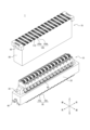
- FIG. 2 is an external perspective view showing a connector according to an embodiment in a state in which a connection target is connected as viewed from above.
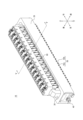
- FIG. 2 is an external perspective view of a connector according to an embodiment in a state where it is separated from an object to be connected, as viewed from above.
- FIG. 2 is an external perspective view of the connector shown in FIG. 1 when viewed from above.
- FIG. 4 is an exploded perspective view of the connector of FIG. 3 when viewed from above. 4 is a sectional view taken along the VV arrow line in FIG. 3.
- FIG. FIG. 5 is an external perspective view showing the pair of contacts in FIG. 4 when viewed from above.
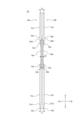
- FIG. 7 is a front view of the pair of contacts in FIG. 6; FIG.
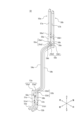
- FIG. 7 is a side view of the pair of contacts in FIG. 6;
- FIG. 7 is an external perspective view showing a pair of contacts according to another example as viewed from above.
- 10 is a front view of the pair of contacts in FIG. 9.
- FIG. 9 is a side view of the pair of contacts in FIG. 9;
- FIG. 5 is an external perspective view showing the pair of contacts and shielding member set of FIG. 4 when viewed from above.
- FIG. 12 is an external perspective view showing four pairs of contacts and shielding members of FIG. 12 as viewed from above.
- 14 is a front view of the pair of contacts and shielding member of FIG. 13.
- FIG. 4 is an external perspective view showing a connection object connected to the connector of FIG. 3 when viewed from above.
- FIG. 16 is an exploded perspective
- the characteristic impedance is adjusted by adjusting the width of the contacts in the arrangement direction of the plurality of contacts.
- the increase in the width of the contacts in the arrangement direction tends to lead to an increase in the size of the connector.
- An increase in plate thickness tends to lead to a decrease in the mobility of the movable insulator.
- the degree of freedom in designing the connector is reduced, and it is difficult to achieve both the adjustment of characteristic impedance required for high-speed transmission and the mobility of the movable insulator.
- the connector and electronic device it is possible to obtain good transmission characteristics in signal transmission while maintaining the mobility of the movable insulator.
- FIG. 1 is an external perspective view of a connector 10 according to an embodiment in a state where a connection target 70 is connected, as viewed from above.
- FIG. 2 is an external perspective view of the connector 10 according to an embodiment in a state where it is separated from the connection target 70 when viewed from above.
- the connector module 1 includes a connector 10 and a connection object 70.
- the connector 10 includes a first insulator 20 as a fixed insulator, a second insulator 30 as a movable insulator, a metal fitting 40, a first contact 50a and a second contact 50b, and a shielding member 60.
- the connection target 70 includes an insulator 80, a metal fitting 90, a first contact 100a and a second contact 100b, and a shielding member 110.
- contact 100 when the first contact 100a and the second contact 100b are not distinguished from each other, they will simply be referred to as "contact 100.”
- the connector 10 is a plug connector.
- the connection target 70 is a receptacle connector.
- the connector 10 in which the portion of the contact 50 that contacts the contact 100 is not elastically deformed in a fitted state in which the second insulator 30 of the connector 10 and the connection target 70 are fitted to each other will be described as a plug connector.
- the connection object 70 in which the portion of the contact 100 that contacts the contact 50 is elastically deformed in the fitted state will be described as a receptacle connector.
- the types of connector 10 and connection target object 70 are not limited to these.
- the connector 10 may serve as a receptacle connector
- the connection object 70 may serve as a plug connector.
- the connector 10 and the connection object 70 are mounted on the circuit boards CB1 and CB2, respectively.
- the connector 10 electrically connects the circuit board CB2 on which the connection object 70 is mounted and the circuit board CB1 via the connection object 70 fitted with the second insulator 30 of the connector 10.
- the circuit boards CB1 and CB2 may be rigid boards, or may be any other circuit boards.
- at least one of the circuit boards CB1 and CB2 may be a flexible printed circuit board (FPC).
- the connector 10 and the connection target 70 are connected to each other in a direction perpendicular to the circuit boards CB1 and CB2.
- the connector 10 and the connection target 70 are connected to each other along the vertical direction, for example.
- the fitting direction when the second insulator 30 and the connection target 70 are fitted to each other is orthogonal to the circuit board CB1.
- connection method is not limited to this.
- the connector 10 and the connection target 70 may be connected to each other in a direction parallel to the circuit boards CB1 and CB2.
- the connector 10 and the connection target 70 are connected to each other such that one side is perpendicular to the circuit board on which it is mounted, and the other is parallel to the circuit board on which it is mounted. Good too.
- the “fitting direction” used in the following description means, for example, the vertical direction.
- the lateral direction of the connector 10 means, for example, the front-back direction.
- the “longitudinal direction of the connector 10” means, for example, the left-right direction.
- the arrangement direction of the plurality of pairs of contacts 50 has the same meaning as the arrangement direction of the plurality of contacts 50, and means the left-right direction as an example.
- the "fitting side” means, for example, the lower side.
- the “extraction side” means, for example, the upper side.
- the “fitted state” refers to a state in which the second insulator 30 of the connector 10 and the connection target 70 are fitted to each other, and the contact 100 is elastically deformed by contact with the contact 50. .
- the “unfitted state” means a state in which the second insulator 30 of the connector 10 and the connection target 70 are not fitted to each other, and the contact 100 is not elastically deformed by external force.
- “Along” means in a plane parallel to the target component or direction. Without being limited thereto, “along” may mean a curved surface, an oblique direction, etc. with respect to a target component or direction.
- the first shielding part 61a when it is written that "the first shielding part 61a is arranged so as to overlap the contact 50 "along the first direction", the first shielding part 61a is arranged in a plane parallel to the first direction.” It may be arranged so as to overlap the contact 50 in a shape, it may be arranged so as to overlap the contact 50 in a curved shape with respect to the first direction, or it may be arranged so as to overlap the contact 50 in a curved shape with respect to the first direction. They may be arranged so as to overlap.
- the connector 10 has a floating structure.
- the connector 10 allows the connected object 70 to move relative to the circuit board CB1 along six directions: up, down, front, back, left and right. Even when connected to the connector 10, the connection target 70 can move within a predetermined range in six directions, including up, down, front, back, left and right directions, with respect to the circuit board CB1.
- the connection target 70 may be able to move within a predetermined range in addition to the six directions of up, down, front, back, left, and right, as well as in diagonal directions between the six directions.
- FIG. 3 is an external perspective view of the connector 10 shown in FIG. 1 when viewed from above.
- FIG. 4 is an exploded perspective view of the connector 10 of FIG. 3 when viewed from above.
- FIG. 5 is a cross-sectional view taken along the VV arrow line in FIG. 3.
- FIG. 6 is an external perspective view showing the pair of contacts 50 in FIG. 4 when viewed from above.
- FIG. 7 is a front view of the pair of contacts 50 in FIG. 6.
- FIG. 8 is a side view of the pair of contacts 50 in FIG. 6.
- the connector 10 is assembled by the following method, for example.
- the metal fitting 40 is press-fitted into the first insulator 20 from below.
- the second insulator 30 is placed from above with respect to the first insulator 20.
- the contact 50 is press-fitted into the first insulator 20 and the second insulator 30 from below.
- the shielding member 60 is press-fitted into the first insulator 20 and the second insulator 30 from below.
- the first insulator 20 is a member extending in the left-right direction and made by injection molding of an insulating and heat-resistant synthetic resin material.
- the first insulator 20 has a frame shape.
- the first insulator 20 has openings 21a and 21b on the upper and lower surfaces, respectively.
- the first insulator 20 is composed of four side surfaces and has an outer peripheral wall 22 surrounding an internal space. More specifically, the outer peripheral wall 22 has a pair of short walls 22a on both left and right sides and a pair of long walls 22b on both front and rear sides.
- the pair of short walls 22a and the pair of long walls 22b are orthogonal to each other and constitute the outer peripheral wall 22.
- the first insulator 20 has a first regulating portion 23a formed by the inner surface of the short side wall 22a.
- the first insulator 20 has a second restriction portion 23b formed by the inner surface of the longitudinal wall 22b.
- the first insulator 20 has a metal fitting groove 24 recessed almost entirely inside the short side wall 22a. A metal fitting 40 is attached to the metal fitting groove 24.
- the first insulator 20 has a plurality of contact mounting grooves 25 extending vertically on the inner surface of the longitudinal wall 22b.
- the contact mounting groove 25 has a first contact mounting groove 25a and a second contact mounting groove 25b.
- a plurality of contacts 50 are respectively attached to the plurality of contact attachment grooves 25 . More specifically, a plurality of first contacts 50a are respectively attached to the plurality of first contact attaching grooves 25a.
- a plurality of second contacts 50b are respectively attached to the plurality of second contact attachment grooves 25b.
- the plurality of pairs of contact mounting grooves 25 are arranged side by side and spaced apart from each other at a predetermined interval along the left-right direction.
- the first insulator 20 has a plurality of mounting grooves 26 extending vertically on the inner surface of the longitudinal wall 22b.
- the mounting grooves 26 are arranged symmetrically on both sides of the contact mounting groove 25 so as to sandwich the contact mounting groove 25 from both sides in the left-right direction.
- a plurality of shielding members 60 are respectively attached to the plurality of attachment grooves 26 .
- the plurality of attachment grooves 26 are recessed and lined up in a state spaced apart from each other at a predetermined interval along the left-right direction.
- the first insulator 20 has a pair of contact mounting grooves 25 and a pair of mounting grooves 26, which are arranged to face each other on the longitudinal walls 22b on both the front and rear sides, as one set, and one set and another set. It has a partition portion 27 that partitions the area in the left-right direction. The partition portion 27 is disposed inside the outer circumferential wall 22 over substantially the entire vertical direction, and extends so as to connect one longitudinal wall 22b and the other longitudinal wall 22b along the front-rear direction.
- the configuration of the second insulator 30 will be explained with reference mainly to FIG. 4.
- the second insulator 30 is disposed through the opening 21a in an internal space surrounded by the outer peripheral wall 22 of the first insulator 20, and is movable relative to the first insulator 20.
- the second insulator 30 fits into the connection target 70.
- the second insulator 30 is a member extending in the left-right direction and made by injection molding of an insulating and heat-resistant synthetic resin material.
- the second insulator 30 has a base portion 31 extending in the left-right direction at an upper portion.
- the second insulator 30 has a fitting convex portion 32 that protrudes upward at the central portion of the base portion 31 in the front-rear direction and that fits into the connection target 70 .
- the second insulator 30 has a plurality of fitting recesses 33 formed in the base 31 along the left-right direction on both sides of the fitting convex portion 32 in the front-rear direction.
- the second insulator 30 has a plurality of contact mounting grooves 34 that are recessed in the outer surface of the fitting protrusion 32 in the front-rear direction and extend over substantially the entire vertical direction of the fitting protrusion 32 .
- the contact mounting groove 34 has a first contact mounting groove 34a and a second contact mounting groove 34b.
- a plurality of contacts 50 are respectively attached to the plurality of contact attachment grooves 34. More specifically, a plurality of first contacts 50a are respectively attached to the plurality of first contact attaching grooves 34a.
- a plurality of second contacts 50b are respectively attached to the plurality of second contact attachment grooves 34b.
- the plurality of pairs of contact mounting grooves 34 are arranged side by side and spaced apart from each other at a predetermined interval along the left-right direction.
- the second insulator 30 has a plurality of mounting grooves 35 that are arranged along both inner surfaces of the fitting recess 33 in the left-right direction and extending into the fitting protrusion 32 .
- the mounting groove 35 is arranged symmetrically with respect to the contact mounting groove 34 so as to surround the contact mounting groove 34 from both sides in the left-right direction and from the center side of the second insulator 30 in the front-back direction.
- a plurality of shielding members 60 are attached to the plurality of attachment grooves 35, respectively.
- the plurality of attachment grooves 35 are recessed and lined up in a state spaced apart from each other at a predetermined interval along the left-right direction.
- the second insulator 30 has regulated portions 36 that protrude one step outward in the left-right direction on both left and right sides of the lower end portion of the base portion 31 and extend downward.
- the second insulator 30 has a first regulated portion 36a formed by the outer surface of the regulated portion 36 in the left-right direction.
- the second insulator 30 has a second regulated portion 36b formed by the outer surface of the regulated portion 36 in the front-rear direction.
- the configuration of the metal fitting 40 will be described with reference mainly to FIG. 4.
- the metal fitting 40 is formed by molding a thin plate of any metal material into the shape shown in FIG. 4 using a progressive die (stamping).
- the method for processing the metal fitting 40 includes a step of bending the metal fitting 40 in the thickness direction after punching the metal fitting 40.
- the metal fitting 40 has an H-shape when viewed from the left and right sides.
- the metal fitting 40 has mounting portions 41 extending outward in a U-shape at its lower end portions on both its front and rear sides.
- the metal fitting 40 has a locking part 42 extending upward from the upper end of the mounting part 41.
- the metal fitting 40 has a base portion 43 extending in the front-back direction so as to connect the locking portions 42 on both the front and rear sides.
- the configuration of the contact 50 will be described with reference mainly to FIGS. 4 to 8.
- the contact 50 is formed by stamping a thin plate of a spring-elastic copper alloy containing phosphor bronze, beryllium copper, or titanium copper, or a Corson copper alloy into the shape shown in FIGS. 4 to 8 using a progressive die (stamping). It is molded.
- the contact 50 is manufactured by punching and then bending it in the thickness direction.
- the contact 50 includes, for example, a metal material with a small elastic modulus so that the shape change due to elastic deformation is large.
- the surface of the contact 50 is plated with gold, tin, or the like after forming a base with nickel plating.
- a plurality of pairs of contacts 50 are arranged along the longitudinal direction of the connector 10.
- a plurality of contacts 50 are arranged along the longitudinal direction of the connector 10.
- the contact 50 is attached to the first insulator 20 and the second insulator 30.
- a pair of contacts 50 arranged at the same left and right positions are arranged symmetrically with respect to each other along the front-rear direction.
- the pair of contacts 50 are arranged so as to be symmetrical to each other with respect to the vertical axis passing through the center between them.
- the pairs of contacts 50 arranged at the same front and back positions are arranged symmetrically with respect to each other along the arrangement direction of the plurality of pairs of contacts 50.
- the pair of contacts 50 are arranged so as to be symmetrical to each other with respect to the vertical axis passing through the center between them.
- the first contact 50a of the pair of contacts 50 has a first base portion 51a that extends along the vertical direction and is supported by the first insulator 20.
- the first base portion 51a has a first held portion 51a1 located below the first base portion 51a.
- the first contact 50a has a mounting portion 52a extending outward in an L-shape from the lower end of the first held portion 51a1.
- the first base portion 51a extends along the first insulator 20 from the mounting portion 52a and is arranged along the first insulator 20.
- the first contact 50a has a first connecting portion 53a that is bent in an L-shape at an angle of approximately 90° from the upper end of the first base portion 51a toward the second insulator 30, that is, inward in the front-rear direction.
- the first connecting portion 53a corresponds to a first bent portion described in the claims.
- the first contact 50a has an elastic part 54a that is connected to the first connecting part 53a and can be elastically deformed.
- the first contact 50a has a second connecting portion 55a bent outward in the left-right direction at an angle of approximately 90° in an L-shape from the end of the elastic portion 54a.
- the second connecting portion 55a corresponds to a second bent portion described in the claims.
- the first contact 50a has a second base portion 56a that extends along the vertical direction and is supported by the second insulator 30.
- the second base portion 56a has a second held portion 56a1 on the second insulator 30 side, which corresponds to the first held portion 51a1.
- the second held portion 56a1 is wide in the left-right direction in the second base portion 56a.
- the second base portion 56a extends along the second insulator 30 from the second connection portion 55a, and is arranged along the second insulator 30.
- the first contact 50a has a contact portion 57a disposed on the outer surface of the second base portion 56a in the front-rear direction.
- the first contact 50a has a first notch portion 58a arranged along the vertical direction between a wide portion in the left-right direction in the first base portion 51a and the first connecting portion 53a.
- a portion of the first base portion 51a that is wide in the left-right direction and a portion of the first connecting portion 53a face each other in the vertical direction via the first notch portion 58a.
- the first contact 50a has a second notch 59a disposed along the vertical direction between a portion of the second base portion 56a that is wide in the left-right direction and the second connecting portion 55a.
- a portion of the second base portion 56a that is wide in the left-right direction and a portion of the second connecting portion 55a face each other in the vertical direction via the second notch portion 59a.
- the first connecting portion 53a connects one end of the elastic portion 54a and the first base portion 51a.
- the second connecting portion 55a connects the other end of the elastic portion 54a and the second base portion 56a.
- the elastic part 54a that can be elastically deformed is arranged between the first base part 51a and the second base part 56a. More specifically, the elastic part 54a is arranged between the first connecting part 53a and the second connecting part 55a.
- the elastic portion 54a has a first extending portion 54a1 that extends linearly from the first connecting portion 53a toward the second insulator 30 side.
- the elastic portion 54a has a first bent portion 54a2 that extends obliquely downward once from the first extended portion 54a1 and is bent into a C-shape as a whole.
- the first bent portion 54a2 is bent in a gentle R shape from the first extending portion 54a1, and has an arcuate end portion facing the first insulator 20 side.
- the first bent portion 54a2 has a fan-shaped arc shape having a central angle of 180° or more.
- the elastic portion 54a has a second extending portion 54a3 that is further bent in an L-shape from the first bent portion 54a2 and linearly extends upward.
- the elastic portion 54a has a second bent portion 54a4 that extends diagonally upward once from the second extended portion 54a3 and is bent in an inverted C-shape as a whole.
- the second bent portion 54a4 is bent in a gentle R shape from the second extension portion 54a3, and has an arcuate end portion facing the second insulator 30 side.
- the second bent portion 54a4 has a fan-shaped arc shape having a central angle of 180° or more.
- the elastic portion 54a has a third extending portion 54a5 that linearly extends from the second bent portion 54a4 toward the second insulator 30 side.
- the second contact 50b has a first base portion 51b that extends along the vertical direction and is supported by the first insulator 20.
- the first base portion 51b has a first held portion 51b1 located below the first base portion 51b.
- the second contact 50b has a mounting portion 52b extending outward in an L-shape from the lower end of the first held portion 51b1.
- the first base portion 51b extends along the first insulator 20 from the mounting portion 52b and is arranged along the first insulator 20.
- the second contact 50b has a first connecting portion 53b bent in an L-shape at an angle of approximately 90° from the upper end of the first base portion 51b toward the second insulator 30, that is, inward in the front-rear direction.
- the first connecting portion 53b corresponds to a first bent portion described in the claims.
- the second contact 50b has an elastic part 54b that is connected to the first connecting part 53b and can be elastically deformed.
- the second contact 50b has a second connecting portion 55b bent outward in the left-right direction at an angle of approximately 90° in an L-shape from the end of the elastic portion 54b.
- the second connecting portion 55b corresponds to a second bent portion described in the claims.
- the second contact 50b has a second base portion 56b that extends along the vertical direction and is supported by the second insulator 30.
- the second base portion 56b has a second held portion 56b1 on the second insulator 30 side, which corresponds to the first held portion 51b1.
- the second held portion 56b1 is wide in the left-right direction at the second base portion 56b.
- the second base portion 56b extends along the second insulator 30 from the second connection portion 55b and is arranged along the second insulator 30.
- the second contact 50b has a contact portion 57b disposed on the outer surface of the second base portion 56b in the front-rear direction.
- the second contact 50b has a first notch 58b that is arranged along the vertical direction between a portion that is wide in the left-right direction in the first base 51b and the first connecting portion 53b.
- a portion of the first base portion 51b that is wide in the left-right direction and a portion of the first connecting portion 53b face each other in the vertical direction via the first notch portion 58b.
- the second contact 50b has a second notch portion 59b arranged along the vertical direction between a wide portion in the left-right direction in the second base portion 56b and the second connecting portion 55b.
- a portion of the second base portion 56b that is wide in the left-right direction and a portion of the second connecting portion 55b face each other in the vertical direction via the second notch portion 59b.
- the first connecting portion 53b connects one end of the elastic portion 54b and the first base portion 51b.
- the second connecting portion 55b connects the other end of the elastic portion 54b and the second base portion 56b.
- the elastic portion 54b that can be elastically deformed is arranged between the first base portion 51b and the second base portion 56b. More specifically, the elastic part 54b is arranged between the first connecting part 53b and the second connecting part 55b.
- the elastic portion 54b has a first extending portion 54b1 that linearly extends from the first connecting portion 53b toward the second insulator 30 side.
- the elastic portion 54b has a first bent portion 54b2 that extends once diagonally downward from the first extended portion 54b1 and is bent into a C-shape as a whole.
- the first bent portion 54b2 is bent in a gentle R shape from the first extending portion 54b1, and has an arcuate end portion facing the first insulator 20 side.
- the first bent portion 54b2 has a fan-shaped arc shape having a central angle of 180° or more.
- the elastic portion 54b has a second extending portion 54b3 that is further bent in an L-shape from the first bent portion 54b2 and extends linearly upward.
- the elastic portion 54b has a second bent portion 54b4 that extends obliquely upward once from the second extended portion 54b3 and is bent in an inverted C-shape as a whole.
- the second bent portion 54b4 is bent in a gentle R shape from the second extending portion 54b3, and has an arcuate end portion facing the second insulator 30 side.
- the second bent portion 54b4 has a fan-shaped arc shape having a central angle of 180° or more.
- the elastic portion 54b has a third extending portion 54b5 that linearly extends from the second bent portion 54b4 toward the second insulator 30 side.
- FIG. 9 is a top perspective view of a pair of contacts 50 according to another example.
- FIG. 10 is a front view of the pair of contacts 50 in FIG.
- FIG. 11 is a side view of the pair of contacts 50 in FIG.
- the shape of the contact 50 is not limited to those shown in FIGS. 4 to 8.
- the contact 50 may have the same components as those shown in FIGS. 4 to 8, but may have a different shape. More specifically, in the first contact 50a and the second contact 50b, the first base portion 51a and the first base portion 51b may be shorter in the vertical direction, respectively.
- the shapes of the elastic portions 54a and 54b of the first contacts 50a and the second contacts 50b may be greatly different from each other. As shown in FIGS. 9 to 11, each of the elastic portions 54a and 54b may have a crank shape when viewed from the left and right side.
- elastic part 54a and the elastic part 54b are not distinguished from each other, they will simply be referred to as “elastic part 54."
- elastic part 54 when other components between the first contact 50a and the second contact 50b are not distinguished from each other, "a" and “b” are omitted and only the corresponding numbers are used.
- the first surface perpendicular to the plate thickness direction of the contact 50 is the elastic portion 54b of the second contact 50b. Facing the first side of.
- the first surface of the entire elastic portion 54b perpendicular to the plate thickness direction of the contact 50 faces the first surface of the elastic portion 54a of the first contact 50a.
- the "first surface” is, for example, a rolled surface.
- the first surface of the elastic portion 54 is, for example, a surface facing in the left-right direction.
- the first surfaces of the entire pair of elastic parts 54 face each other in the arrangement direction of the plurality of pairs of contacts 50.
- the pair of first bases 51 face each other in the arrangement direction of the plurality of pairs of contacts 50, with second surfaces parallel to the plate thickness direction of the contacts 50.
- the pair of second base portions 56 face each other in the arrangement direction of the plurality of pairs of contacts 50, with second surfaces parallel to the plate thickness direction of the contacts 50.
- the "second surface” is, for example, a fractured surface.
- the second surface of the first base 51 and the second surface of the second base 56 are, for example, surfaces facing in the left-right direction.
- the rolled surfaces of the first base portion 51 and the second base portion 56 are surfaces facing in the front-rear direction, while the rolled surfaces of the elastic portion 54 are surfaces facing in the left-right direction.
- the fractured surfaces of the first base 51 and the second base 56 face in the left-right direction, while the fractured surfaces of the elastic part 54 face in various directions perpendicular to the left-right direction.
- the first connecting portion 53a and the second connecting portion 55a have a first portion 53a1 and a first portion 55a1, respectively.
- the first portion 53a1 moves the second contact from the corresponding first base 51a along the arrangement direction of the plurality of pairs of contacts 50 so that the elastic part 54a approaches the elastic part 54b of the second contact 50b along the arrangement direction of the plurality of pairs of contacts 50. Extends to the 50b side.
- the first portion 53a1 extends from the corresponding first base 51a to the second contact along the arrangement direction so that the distance between the pair of elastic parts 54 is narrower than the arrangement distance between the pair of contacts 50 along the arrangement direction. Extends to the 50b side.
- the first portion 55a1 moves the second contact from the corresponding second base 56a along the arrangement direction of the plurality of pairs of contacts 50 so that the elastic part 54a approaches the elastic part 54b of the second contact 50b along the arrangement direction of the plurality of pairs of contacts 50. Extends to the 50b side.
- the first portion 55a1 connects the second contacts along the arrangement direction from the corresponding second base 56a so that the distance between the pair of elastic parts 54 is narrower than the arrangement distance between the pair of contacts 50 along the arrangement direction. Extends to the 50b side.
- the first connecting portion 53b and the second connecting portion 55b have a first portion 53b1 and a first portion 55b1, respectively.
- the first portion 53b1 moves the first contact from the corresponding first base 51b along the arrangement direction of the plurality of pairs of contacts 50 so that the elastic part 54b approaches the elastic part 54a of the first contact 50a along the arrangement direction of the plurality of pairs of contacts 50. Extends to the 50a side.
- the first portion 53b1 connects the first contacts along the arrangement direction from the corresponding first base portion 51b such that the distance between the pair of elastic parts 54 is narrower than the arrangement distance between the pair of contacts 50 along the arrangement direction. Extends to the 50a side.
- the first portion 55b1 connects the first contact from the corresponding second base portion 56b along the arrangement direction of the plurality of pairs of contacts 50 so that the elastic part 54b approaches the elastic part 54a of the first contact 50a along the arrangement direction of the plurality of pairs of contacts 50. Extends to the 50a side.
- the first portion 55b1 connects the first contacts along the arrangement direction from the corresponding second base portion 56b such that the distance between the pair of elastic parts 54 is narrower than the arrangement distance between the pair of contacts 50 along the arrangement direction. Extends to the 50a side.
- the first connecting portion 53 connects the first base portion 51 and the elastic portion 54 such that the pair of elastic portions 54 are located further inside the pair of first base portions 51 along the arrangement direction. More specifically, the first connecting portion 53 is connected to the first base portion 51 so that the outer edge portions of the pair of elastic portions 54 are located inside the outer edge portions of the pair of first base portions 51 in the arrangement direction. 54. The first connecting portion 53 connects the first base portion 51 and the elastic portion 54 such that the center line of the elastic portion 54 is located inside the center line of the first base portion 51 in the arrangement direction.
- the second connecting portion 55 connects the second base portion 56 and the elastic portion 54 such that the pair of elastic portions 54 are located further inside the pair of second base portions 56 along the arrangement direction. More specifically, the second connecting portion 55 is connected to the second base portion 56 so that the outer edge portions of the pair of elastic portions 54 are located inside the outer edge portions of the pair of second base portions 56 in the arrangement direction. 54. The second connecting portion 55 connects the second base portion 56 and the elastic portion 54 such that the center line of the elastic portion 54 is located inside the center line of the second base portion 56 in the arrangement direction.
- the distance L0 between the pair of center lines of the pair of elastic parts 54 is the distance L1 between the pair of center lines of the pair of first base parts 51. and shorter than the distance L2 between the pair of center lines of the pair of second bases 56.
- the first connecting portion 53a and the second connecting portion 55a have a second portion 53a2 and a second portion 55a2, respectively.
- the second portion 53a2 is bent from the first portion 53a1 toward the other insulator, that is, the second insulator 30 side.
- the second portion 55a2 is bent from the first portion 55a1 toward the other insulator, that is, the first insulator 20 side.
- the first connecting portion 53b and the second connecting portion 55b have a second portion 53b2 and a second portion 55b2, respectively.
- the second portion 53b2 is bent from the first portion 53b1 toward the other insulator, that is, the second insulator 30 side.
- the second portion 55b2 is bent from the first portion 55b1 toward the other insulator, that is, the first insulator 20 side.
- the pair of first notches 58 that each of the pair of contacts 50 has is located on the inner side of the pair of contacts 50 in the left-right direction.
- the pair of first notches 58 face each other inside the pair of contacts 50 in the left-right direction.
- the pair of second notches 59 that each of the pair of contacts 50 has is located on the inner side of the pair of contacts 50 in the left-right direction.
- the pair of second notches 59 face each other inside the pair of contacts 50 in the left-right direction.
- the width at which the pair of elastic portions 54 overlap each other in the direction orthogonal to the extending direction of the contacts 50 is The width is larger than the width at which the first base portion 51 overlaps with each other and the width at which the pair of second base portions 56 overlap with each other.
- the direction orthogonal to the extending direction of the contact 50 is, for example, in the crank-shaped elastic portion 54 as shown in FIG. It is.
- the direction perpendicular to the extending direction of the contact 50 is, for example, the radial direction of the radius of curvature of the elastic portion 54 having each gently curved bent portion as shown in FIG. 8 .
- FIG. 12 is an external perspective view of the set of the pair of contacts 50 and shielding member 60 shown in FIG. 4 when viewed from above.
- FIG. 13 is an external perspective view showing four pairs of contacts 50 and shielding member 60 of FIG. 12 as viewed from above.
- FIG. 14 is a front view of the pair of contacts 50 and shielding member 60 of FIG. 13.
- the configuration of the shielding member 60 will be described with reference mainly to FIGS. 4 and 12 to 14.
- the shielding member 60 is formed by molding a thin plate of any metal material into the shape shown in FIGS. 4 and 12 to 14 using a progressive die (stamping).
- the method for processing the shielding member 60 includes a step of punching and then bending the shielding member in the thickness direction.
- the shielding member 60 has a shape along three consecutive sides of a rectangle when viewed from above.
- a plurality of shielding members 60 are arranged along the longitudinal direction of the connector 10.
- the shielding member 60 is attached to the first insulator 20 and the second insulator 30. More specifically, the shielding member 60 includes a first shielding member 60a attached to the second insulator 30 and a second shielding member 60b attached to the first insulator 20.
- the pair of shielding members 60 arranged at the same left and right positions are arranged symmetrically with respect to each other along the front-rear direction.
- the pair of shielding members 60 are arranged in point symmetry with respect to a center point located between them when viewed from above.
- the pair of shielding members 60 arranged at the same front and rear positions have the same shape and arrangement along the arrangement direction of the plurality of pairs of contacts 50.
- the first shielding member 60a has a pair of first shielding parts 61a that extend in a plane along the front-rear direction.
- the first shielding member 60a has a second shielding part 62a that extends in a planar shape along the left-right direction and connects a pair of first shielding parts 61a spaced apart in the front-back direction along the left-right direction.
- the first shielding member 60a has a first held portion 63a that linearly extends upward from the center of the upper edge of the second shielding portion 62a.
- the second shielding member 60b has a pair of third shielding parts 61b that extend planarly along the front-rear direction.
- the second shielding member 60b has a fourth shielding part 62b that extends in a plane along the left-right direction and connects a pair of third shielding parts 61b spaced apart in the front-back direction along the left-right direction.
- the second shielding member 60b has a second held portion 63b that linearly extends upward from the upper end at the front-rear end of the third shielding portion 61b.
- the second shielding member 60b has a mounting portion 64b extending linearly outward in the front-rear direction from the lower end at the end in the front-rear direction of the third shield portion 61b.
- the second shielding member 60b has a first spring piece 65b that is elastically deformable at the center in the front-rear direction at the lower part of the third shielding part 61b.
- the second shielding member 60b has a second spring piece 66b that is elastically deformable on the inside in the front-rear direction at the lower part of the other third shielding part 61b.
- the shielding member 60 has an elastically deformable connecting part 67 that connects the lower edge of the second shielding part 62a of the first shielding member 60a and the upper edge of the fourth shielding part 62b of the second shielding member 60b.
- the connecting portion 67 extends in a J-shape from the lower edge of the second shielding portion 62a, is further bent in an inverted U-shape, and is connected to the upper edge of the fourth shielding portion 62b.
- the shielding member 60 is disposed between one pair of contacts 50 and the other pair.
- the first shielding member 60a is arranged between the plurality of contacts 50.
- the second shielding member 60b is arranged between the plurality of contacts 50.
- the first shielding part 61a of the first shielding member 60a is arranged so as to overlap the contact 50 along a first direction that intersects with the fitting direction when the connection target 70 and the second insulator 30 are fitted to each other. ing.
- the "first direction” means, as an example, the front-back direction.
- the first shielding part 61a is arranged in a plane along the first direction and overlaps with the contact 50.
- the second shielding part 62a of the first shielding member 60a overlaps with the contact 50 along the fitting direction when the connection target 70 and the second insulator 30 are fitted to each other and the second direction intersecting the first direction. It is arranged like this.
- the "second direction" means, for example, the left-right direction.
- the second shielding part 62a is arranged in a plane along the second direction and overlaps with the contact 50.
- the third shielding part 61b of the second shielding member 60b is arranged so as to overlap the contact 50 along the first direction intersecting the fitting direction when the connection target 70 and the second insulator 30 are fitted to each other. ing.
- the third shielding part 61b is arranged in a plane along the first direction and overlaps with the contact 50.
- the fourth shielding part 62b of the second shielding member 60b overlaps with the contact 50 along the fitting direction when the connection target 70 and the second insulator 30 are fitted to each other and the second direction intersecting the first direction. It is arranged like this.
- the fourth shielding part 62b is arranged in a plane along the second direction and overlaps with the contact 50.
- the first shielding member 60a surrounds the portion of the contact 50 located above the center of the elastic portion 54 from both sides in the left-right direction and from the inside in the front-rear direction.
- the second shielding member 60b surrounds a portion of the contact 50 located below the center of the elastic portion 54 from both sides in the left-right direction and from the inside in the front-back direction.
- the first shielding member 60a and the second shielding member 60b are arranged so as to partially overlap each other along the fitting direction.
- the first shielding member 60a and the second shielding member 60b are connected to each other at a connecting portion 67.
- a plurality of second shielding members 60b are arranged in the first direction and the second direction.
- a pair of second shielding members 60b adjacent in the first direction are in contact with each other through surface contact by a pair of fourth shielding parts 62b.
- the first spring piece 65b of one second shielding member 60b is close to the third shielding part 61b of the other second shielding member 60b.
- the second spring piece 66b of the other second shielding member 60b is arranged close to the third shielding portion 61b of one second shielding member 60b.
- a plurality of first shielding members 60a are arranged in the first direction and the second direction.
- a pair of first shielding members 60a adjacent in the first direction are spaced apart from each other with a pair of connecting portions 67 in between.
- a pair of first shielding members 60a adjacent in the second direction are spaced apart from each other.
- the distance between the first base 51 of the contact 50 and the second shielding member 60b remains constant even when the second insulator 30 moves relative to the first insulator 20. More specifically, the distance in the left-right direction between the first base portion 51 and the third shielding portion 61b located outside the first base portion 51 in the left-right direction is constant.
- the distance between the second base portion 56 of the contact 50 and the first shielding member 60a remains constant even when the second insulator 30 moves relative to the first insulator 20. More specifically, the distance in the left-right direction between the second base portion 56 and the first shielding portion 61a located outside the second base portion 56 in the left-right direction is constant.
- the distance between the elastic portion 54 of the contact 50 and the first shielding member 60a is larger than the distance between the second base 56 and the first shielding member 60a. More specifically, the distance in the left-right direction between the elastic portion 54 and the first shielding portion 61a located on the outside in the left-right direction is equal to the distance between the second base portion 56 and the first shielding portion 61a located on the outside in the left-right direction. is larger than the horizontal distance of .
- the distance between the elastic portion 54 of the contact 50 and the second shielding member 60b is larger than the distance between the first base 51 and the second shielding member 60b. More specifically, the distance in the left-right direction between the elastic part 54 and the third shielding part 61b located outside in the left-right direction is equal to the distance between the first base 51 and the third shielding part 61b located outside in the left-right direction. is larger than the horizontal distance of .
- the first base portion 51 of the contact 50 is engaged with the contact mounting groove 25 arranged in the longitudinal wall 22b of the first insulator 20.
- the first base 51 is attached to the first insulator 20. More specifically, the first base portion 51a of the first contact 50a is engaged with the first contact mounting groove 25a.
- the first base portion 51b of the second contact 50b is engaged with the second contact mounting groove 25b.
- the second base portion 56 of the contact 50 is engaged with the contact mounting groove 34 arranged in the fitting convex portion 32 of the second insulator 30.
- the second base 56 is attached to the second insulator 30. More specifically, the second base portion 56a of the first contact 50a is locked in the first contact mounting groove 34a.
- the second base portion 56b of the second contact 50b is engaged with the second contact mounting groove 34b.
- each contact 50 when the plurality of contacts 50 are attached to the first insulator 20 and the second insulator 30, the contact portion 57 of each contact 50 is located inside the fitting recess 33 of the second insulator 30.
- the contact portion 57 of each contact 50 is arranged along the inner surface of the fitting recess 33 in the front-rear direction so as to face inside the fitting recess 33 .
- Each contact 50 is connected to the second insulator 30 in an internal space surrounded by the outer peripheral wall 22 of the first insulator 20 and directly above the outer peripheral wall 22, with the second insulator 30 spaced apart from the first insulator 20 and in a floating state. is supported.
- the second insulator 30 When the second insulator 30 is held with respect to the first insulator 20 by the contact 50, the second insulator 30 is connected to the first insulator 20 in the inner space surrounded by the outer peripheral wall 22 of the first insulator 20 and directly above the outer peripheral wall 22. It is arranged apart from 20. More specifically, the base 31 of the second insulator 30 is located directly above the outer peripheral wall 22.
- the regulated portion 36 of the second insulator 30 is arranged in an internal space of the first insulator 20 surrounded by a pair of longitudinal walls 22b and a pair of short walls 22a. The regulated portion 36 of the second insulator 30 is surrounded by the outer peripheral wall 22 of the first insulator 20 .
- the base 31 of the second insulator 30 protrudes upward from the opening 21a of the first insulator 20 and is located outside the internal space of the first insulator 20.
- the base portion 31 of the second insulator 30 is disposed above the outer peripheral wall 22 of the first insulator 20 so as to be able to fit with the connection target 70 .
- the second regulated portion 36b of the second insulator 30 is located inside the second regulating portion 23b disposed on the longitudinal wall 22b of the first insulator 20 in the front-rear direction. To position. The first regulated portion 36a of the second insulator 30 faces the first regulating portion 23a disposed on the short side wall 22a of the first insulator 20 from the inside in the left-right direction.
- the first held portion 63a of the first shielding member 60a is locked in the mounting groove 35 disposed in the fitting convex portion 32 of the second insulator 30.
- the first held portion 63a is attached to the second insulator 30.
- the second held portion 63b of the second shielding member 60b is engaged with the attachment groove 26 arranged in the longitudinal wall 22b of the first insulator 20.
- the second held portion 63b is attached to the first insulator 20.
- the locking portion 42 of the metal fitting 40 locks into the metal fitting mounting groove 24 of the first insulator 20.
- the metal fittings 40 are press-fitted into the metal fitting grooves 24 of the first insulator 20 and are disposed at both left and right ends of the first insulator 20.
- the connector 10 having the above structure is mounted, for example, on a circuit forming surface disposed on the mounting surface of the circuit board CB1. More specifically, the mounting portion 41 of the metal fitting 40 is placed on solder paste applied to a pattern on the circuit board CB1. The mounting portion 52a of the first contact 50a is placed on the solder paste applied to the pattern on the circuit board CB1. The mounting portion 52b of the second contact 50b is placed on the solder paste applied to the pattern on the circuit board CB1. The mounting portion 64b of the second shielding member 60b is placed on the solder paste applied to the pattern on the circuit board CB1.
- the mounting portion 41, the mounting portion 52a, the mounting portion 52b, and the mounting portion 64b are soldered in the above pattern.
- the mounting of the connector 10 onto the circuit board CB1 is completed.
- connection object 70 The structure of the connection object 70 will be explained mainly with reference to FIGS. 15 and 16.
- FIG. 15 is an external perspective view showing a connection target 70 connected to the connector 10 of FIG. 3 when viewed from above.
- FIG. 16 is an exploded perspective view of the connection target 70 of FIG. 15 when viewed from above.
- connection target 70 is assembled by press-fitting the metal fitting 90 into the insulator 80 from above, and press-fitting the contacts 100 and shielding member 110 from below.
- the insulator 80 is a square prism-shaped member made by injection molding of an insulating and heat-resistant synthetic resin material.
- the insulator 80 has a fitting recess 81 disposed on the upper surface.
- the insulator 80 has a plurality of fitting protrusions 82 arranged inside the fitting recess 81 .
- the insulator 80 has metal fitting grooves 83 arranged along the vertical direction at both left and right ends of the lower end. A metal fitting 90 is attached to the metal fitting groove 83.
- the insulator 80 has a plurality of contact mounting grooves 84 that are recessed in a straight line almost entirely in the vertical direction inside the insulator 80 .
- the contact mounting groove 84 has a first contact mounting groove 84a and a second contact mounting groove 84b.
- a plurality of contacts 100 are respectively attached to the plurality of contact attachment grooves 84 . More specifically, a plurality of first contacts 100a are respectively attached to the plurality of first contact attachment grooves 84a.
- a plurality of second contacts 100b are respectively attached to the plurality of second contact attachment grooves 84b.
- the plurality of pairs of contact mounting grooves 84 are arranged side by side and spaced apart from each other at a predetermined interval along the left-right direction.
- the insulator 80 has a plurality of mounting grooves 85 recessed in a straight line almost entirely in the vertical direction inside the insulator 80 .
- the mounting groove 85 is arranged in a part of the periphery of the contact mounting groove 84 so as to surround the contact mounting groove 84 from both sides in the left-right direction and from inside in the front-back direction.
- a plurality of shielding members 110 are respectively attached to the plurality of attachment grooves 85 .
- the plurality of attachment grooves 85 are recessed and lined up in a state spaced apart from each other at a predetermined interval along the left-right direction.
- the metal fitting 90 is formed by molding a thin plate of any metal material into the shape shown in FIG. 16 using a progressive die (stamping).
- the metal fittings 90 are arranged at both left and right ends of the insulator 80, respectively.
- the metal fitting 90 has an L-shaped mounting portion 91 extending outward in the left-right direction at its lower end.
- the metal fitting 90 has a mounting portion 91 .
- the metal fitting 90 has a locking portion 92 that locks onto the insulator 80.
- the locking portion 92 is connected to the mounting portion 91 at its lower edge.
- the contact 100 is formed by molding a thin plate of a spring-elastic copper alloy containing phosphor bronze, beryllium copper, or titanium copper, or a Corson copper alloy into the shape shown in FIG. 16 using a progressive die (stamping). It is something.
- the contact 100 is manufactured by punching and then bending it in the thickness direction.
- the surface of the contact 100 is plated with gold, tin, or the like after forming a base with nickel plating.
- a plurality of pairs of contacts 100 are arranged along the left-right direction.
- a pair of contacts 100 have the same shape.
- the first contact 100a and the second contact 100b have the same shape.
- the contact 100 has a mounting portion 101 that linearly extends outward in the front-rear direction.
- the contact 100 has a connecting portion 102 provided so as to be continuous with the mounting portion 101 .
- the connecting portion 102 has a shape like two inverted L shapes connected to each other. More specifically, the connecting portion 102 extends upward from the mounting portion 101 in a straight line, is bent approximately 90 degrees, and extends in the front-rear direction. The connecting portion 102 is further bent at approximately 90 degrees and extends upward in a straight line, and is bent at approximately 90 degrees and extends in the front-rear direction.
- the contact 100 has a locking part 103 that linearly extends upward from the end of the connecting part 102.
- the contact 100 has an elastic contact piece 104 that can be elastically deformed and extends upward from the locking part 103 while being bent.
- the contact 100 has a contact portion 105 located inside the elastic contact piece 104 in the front-rear direction.
- the shielding member 110 is formed by molding a thin plate of any metal material into the shape shown in FIG. 16 using a progressive die (stamping).
- the method for processing the shielding member 110 includes a step of punching and then bending the shielding member in the thickness direction.
- the shielding member 110 has a shape along three consecutive sides of a rectangle when viewed from above.
- a plurality of shielding members 110 are arranged along the left-right direction.
- Shielding member 110 is attached to insulator 80.
- a pair of shielding members 110 arranged at the same left and right positions are arranged symmetrically with respect to each other along the front-rear direction.
- the pair of shielding members 110 are arranged so as to be symmetrical to each other with respect to the vertical axis passing through the center between them.
- a pair of shielding members 60 arranged at the same front-back position have the same shape and arrangement along the left-right direction.
- the shielding member 110 has a pair of first shielding parts 111 that extend in a plane along the front-rear direction.
- the shielding member 110 has a second shielding part 112 that extends in a planar shape along the left-right direction and connects a pair of first shielding parts 111 spaced apart in the front-back direction along the left-right direction.
- the shielding member 110 has an elastic contact piece 113 that can be elastically deformed and extends upward from the upper end at the end of the first shielding part 111 in the front-rear direction.
- the shielding member 110 has a mounting portion 114 that linearly extends outward in the front-rear direction from the lower end at the end of the first shield portion 111 in the front-rear direction.
- the shielding member 110 is arranged between one pair of contacts 100 and the other pair.
- the shielding member 110 is arranged between the plurality of contacts 100.
- the shielding member 110 surrounds the pair of contacts 100 from both sides in the left-right direction and from inside in the front-back direction.
- the metal fitting 90 is attached to the metal fitting mounting groove 83 of the insulator 80.
- the locking portion 92 of the metal fitting 90 locks into the metal fitting mounting groove 83 of the insulator 80.
- the metal fittings 90 are arranged at both left and right ends of the insulator 80, respectively.
- the plurality of contacts 100 are respectively attached to the plurality of contact mounting grooves 84 of the insulator 80. More specifically, the plurality of first contacts 100a are respectively attached to the plurality of first contact mounting grooves 84a of the insulator 80. The plurality of second contacts 100b are respectively attached to the plurality of second contact mounting grooves 84b of the insulator 80.
- the locking portion 103 of the contact 100 locks in the contact mounting groove 84 of the insulator 80.
- the elastic contact piece 104 of the contact 100 is arranged so as to be elastically deformable along the front-rear direction inside the contact mounting groove 84.
- the contact portion 105 of the elastic contact piece 104 is exposed from the contact mounting groove 84 and located inside the fitting recess 81 .
- connection object 70 having the structure described above is mounted, for example, on a circuit forming surface disposed on the mounting surface of the circuit board CB2. More specifically, the mounting portion 91 of the metal fitting 90 is placed on solder paste applied to a pattern on the circuit board CB2. The mounting portion 101 of the contact 100 is placed on solder paste applied to a pattern on the circuit board CB2. The mounting portion 114 of the shielding member 110 is placed on the solder paste applied to the pattern on the circuit board CB2.
- connection object 70 on the circuit board CB2 is completed.
- electronic components other than the connection target object 70 including, for example, a camera module and a sensor, are mounted.
- FIG. 17 is a cross-sectional view taken along the XVII-XVII arrow line in FIG. 1. The operation of the connector 10 having a floating structure will be mainly described with reference to FIG. 17.
- the first insulator 20 is fixed to the circuit board CB1 by soldering the mounting portion 52 of the contact 50 to the circuit board CB1.
- the second shielding member 60b attached to the first insulator 20 is also fixed to the circuit board CB1.
- the second insulator 30 becomes movable relative to the first insulator 20 fixed to the circuit board CB1 by elastically deforming the contact 50.
- the first shielding member 60a attached to the second insulator 30 is also movable relative to the first insulator 20 as the second insulator 30 moves.
- the first shielding part 61a is movable relative to the first insulator 20 as the second insulator 30 moves.
- the connecting portion 67 connecting the first shielding member 60a and the second shielding member 60b in the shielding member 60 is elastically deformed.
- the second restricting portion 23b of the first insulator 20 restricts excessive movement of the second insulator 30 in the front-rear direction relative to the first insulator 20.
- the second regulated portion 36b of the second insulator 30 comes into contact with the second regulating portion 23b. Thereby, the second insulator 30 does not move further outward in the front-rear direction.
- the first restricting portion 23a of the first insulator 20 restricts excessive movement of the second insulator 30 in the left-right direction with respect to the first insulator 20. For example, when the second insulator 30 moves in the left-right direction by a large amount beyond the design value due to the elastic deformation of the contact 50, the first regulated portion 36a of the second insulator 30 comes into contact with the first regulating portion 23a. As a result, the second insulator 30 does not move further outward in the left-right direction.
- connection object 70 With the vertical direction of the connection object 70 reversed with respect to the connector 10 having the above-described floating structure, the connector 10 and the connection object 70 are connected to each other while making their longitudinal and lateral positions substantially coincident. Make them face each other vertically. After that, the connection target 70 is moved downward. At this time, even if the mutual positions are slightly shifted, for example, in the front, rear, left and right directions, the second insulator 30 moves relative to the first insulator 20 due to the floating structure of the connector 10.
- the fitting protrusion 32 of the second insulator 30 is guided into the fitting recess 81 of the insulator 80.
- the connection target 70 is further moved downward, the fitting protrusion 32 of the second insulator 30 and the fitting recess 81 of the insulator 80 fit into each other.
- the fitting recess 33 of the second insulator 30 and the fitting protrusion 82 of the insulator 80 fit into each other.
- the contacts 50 of the connector 10 and the contacts 100 of the connection object 70 are in contact with each other. . More specifically, the contact portion 57 of the contact 50 and the contact portion 105 of the contact 100 are in contact with each other. The contact portion 57a of the first contact 50a and the contact portion 105 of the first contact 100a are in contact with each other. The contact portion 57b of the second contact 50b and the contact portion 105 of the second contact 100b are in contact with each other.
- the elastic contact piece 104 of the contact 100 is slightly elastically deformed along the front-back direction, and is elastically displaced along the front-back direction inside the contact mounting groove 84.
- the connector 10 and the connection target 70 are completely connected.
- the circuit board CB1 and the circuit board CB2 are electrically connected via the contacts 50 and 100.
- the first shielding member 60a and the shielding member 110 are in contact with each other in the fitted state in which the connector 10 and the connection target 70 are fitted to each other. More specifically, the elastic contact piece 113 of the shielding member 110 contacts the inner surface in the left-right direction of the first shielding portion 61a of the first shielding member 60a.
- the characteristic impedance can be easily adjusted while maintaining the mobility of the movable insulator.
- the connector 10 can obtain good transmission characteristics in signal transmission while maintaining the mobility of the movable insulator.
- the first surface of at least a portion of the elastic portion 54 faces the first surface of the elastic portion 54 of the other contact 50 .
- the pair of contacts 50 face each other with first surfaces having a larger area orthogonal to the thickness direction of the contacts 50. Thereby, an effect similar to that of a capacitor can be obtained between the pair of contacts 50.
- the capacitance is C
- the characteristic impedance Z at this time depends on the capacitance C.
- the characteristic impedance Z is inversely proportional to the square root of the capacitance C, or is inversely proportional to the capacitance C.
- the connector 10 makes it possible to adjust the characteristic impedance while maintaining a design-appropriate spacing between the pair of contacts 50 in the arrangement direction. .
- This makes it possible to adjust the characteristic impedance while maintaining the thickness of the elastic portion 54 of the contact 50 and the width of the first surface in the direction orthogonal to its extending direction. Since the connector 10 can maintain the plate thickness of the elastic portion 54 of the contact 50 and the width of the first surface in the direction orthogonal to the extending direction thereof, the decrease in the mobility of the second insulator 30 can be reduced, and the connector 10 can also be reduced in size.
- the characteristic impedance can be easily adjusted by freely changing the width of the first surface of the elastic portion 54 of the contact 50 in the direction orthogonal to the extending direction. Therefore, in the connector 10, the degree of freedom in design can be improved compared to the case where the pair of elastic parts 54 face each other on the second surface.
- the connector 10 facilitates matching the characteristic impedance value to the ideal value based on the configuration of the capacitor in the elastic portion 54 of the contact 50.
- the connector 10 can improve transmission characteristics in signal transmission while maintaining the mobility of the second insulator 30.
- the connector 10 can realize both the adjustment of characteristic impedance necessary for high-speed transmission and the mobility of the movable insulator, while improving the degree of freedom in its design.
- At least one of the first connecting portion 53 and the second connecting portion 55 has a first portion. This makes it possible to bring the elastic part 54 of one contact 50 closer to the elastic part 54 of another contact 50 along the arrangement direction of the plurality of pairs of contacts 50. Therefore, the capacitance C of the capacitor due to the pair of elastic parts 54 becomes even larger. The characteristic impedance is further reduced. As a result, the above-mentioned effect that it is possible to achieve both adjustment of the characteristic impedance and mobility of the movable insulator while improving the degree of freedom in designing the contact 50 becomes more remarkable.
- At least a portion of the pair of elastic portions 54 face each other in the arrangement direction of the plurality of pairs of contacts 50 on their first surfaces.
- the connector 10 makes it difficult for the effects of stress caused when the elastic portion 54 is elastically deformed to be exerted on the components located from the corresponding base to the end of the contact 50.
- the connector 10 can reduce stress generated in the mounting section 52 when the elastic section 54 is elastically deformed. Therefore, the connector 10 can reduce damage to the mounting portion 52 such as solder cracks, and can improve reliability as a product.
- a pair of first base portions 51 face each other on their second surfaces in the direction in which the plurality of pairs of contacts 50 are arranged.
- the connector 10 can be designed to provide the first held part included in the first base 51 between the elastic part 54 and the mounting part 52, so that when the elastic part 54 is elastically deformed, the mounting part It is possible to further reduce the stress generated at 52. Therefore, the connector 10 can further reduce damage to the mounting portion 52 such as solder cracks, and can further improve reliability as a product.
- the connector 10 can reduce the number of stubs in the locking portion, it is possible to reduce the occurrence of branching of transmission signals at the stubs. Therefore, the connector 10 can improve transmission characteristics in signal transmission.
- a pair of second base portions 56 face each other on their second surfaces in the direction in which the plurality of pairs of contacts 50 are arranged.
- the connector 10 can be designed to provide a second held part included in the second base part 56 between the elastic part 54 and the contact part 57, so that when the elastic part 54 is elastically deformed, the contact part It is possible to further reduce the stress generated at 57. Therefore, the connector 10 can improve the reliability of the contact between the connection target 70 and the contact 100 at the contact portion 57, and further improve the reliability as a product.
- the connector 10 can reduce the number of stubs in the locking portion, it is possible to reduce the occurrence of branching of transmission signals at the stubs. Therefore, the connector 10 can improve transmission characteristics in signal transmission.
- the characteristic impedance of the elastic part 54 since the distance L0 between the pair of elastic parts 54 is shorter than at least one of the distance L1 and the distance L2, the characteristic impedance of the elastic part 54, where the characteristic impedance tends to increase, can be easily lowered.
- the connector 10 more significantly exhibits the above-mentioned effect of being able to realize both the adjustment of characteristic impedance necessary for high-speed transmission and the mobility of the movable insulator while improving the degree of freedom in its design.
- the width at which the pair of elastic parts 54 overlap with each other is equal to the width at which the pair of first base parts 51 overlap with each other and the width at which the pair of second base parts 56 overlap with each other. At least one is bigger than the other.
- the connector 10 improves the symmetry between the pair of contacts 50 by arranging the pairs of contacts 50 in line symmetry with each other along the arrangement direction of the plurality of pairs of contacts 50, thereby improving differential transmission characteristics. It is possible to improve In a conventional pair of contacts having the same shape, the interval between the elastic parts was determined by the pitch interval between the pair of contacts, that is, the interval in the arrangement direction of the pair of mounting parts. Unlike such conventional contacts, in the connector 10, the pair of contacts 50 have different shapes from each other, so that the left-right direction between the pair of first surfaces facing each other in the pair of elastic parts 54 is maintained without changing the pitch interval. You can change the spacing.
- the pair of first notches 58 are arranged in the pair of contacts 50, so that the contacts 50 can be easily bent.
- the pair of second notches 59 are respectively arranged in the pair of contacts 50, so that the contacts 50 can be easily bent.
- the connector 10 can improve the noise shielding effect by having the shielding member 60 disposed between one pair of the contacts 50 and the other pair. For example, the inflow of electromagnetic wave noise from the outside into the plurality of pairs of contacts 50 and the outflow of electromagnetic wave noise from the plurality of pairs of contacts 50 to the outside are effectively reduced. For example, crosstalk between the plurality of contacts 50 is effectively reduced. As a result, the connector 10 can obtain good transmission characteristics for high-frequency signals even in high-speed transmission.
- the above effects are obtained when the shielding member 60 shields one contact 50 from another contact 50, and when the shielding member 60 shields one set and another set of three or more contacts 50. The same applies to the later-described modified example of the case where
- the connector 10 According to the connector 10 according to the embodiment as described above, it is possible to obtain good transmission characteristics in signal transmission even when a floating structure is used.
- the first shielding member 60a since the first shielding member 60a has the first shielding portion 61a, the above-mentioned noise shielding effect is improved in the longitudinal direction of the connector 10.
- the first shielding portion 61a is movable relative to the first insulator 20 as the second insulator 30 moves, so that the first shielding portion 61a is a portion of the contact 50 disposed on the second insulator 30 side. It is possible to move with Therefore, even during the floating operation, contact between the first shielding portion 61a and the contact 50 is reduced.
- the first shielding member 60a has the second shielding part 62a, the above-described noise shielding effect is improved in the lateral direction of the connector 10.
- the connector 10 By including the second shielding member 60b in addition to the first shielding member 60a, the connector 10 exhibits the above-mentioned effect of improving the noise shielding effect more significantly.
- the second shielding member 60b has the third shielding part 61b, the above-mentioned noise shielding effect is more significantly improved in the longitudinal direction of the connector 10.
- the second shielding member 60b has the fourth shielding part 62b, the above-mentioned noise shielding effect is more significantly improved in the lateral direction of the connector 10.
- the first shielding member 60a and the second shielding member 60b are connected to each other, so that the first shielding member 60a and the second shielding member 60b can be configured as one shielding member 60. , it is possible to further improve the above noise shielding effect.
- the connector 10 by arranging a plurality of first shielding members 60a in at least one of the first direction and the second direction, it is possible to further improve the above-mentioned noise shielding effect as a whole.
- the connector 10 by arranging a plurality of second shielding members 60b in at least one of the first direction and the second direction, it is possible to further improve the above-mentioned noise shielding effect as a whole.
- the distance between the second base 56 and the first shielding member 60a is constant even when the second insulator 30 moves, so that disturbances in the characteristic impedance at the second base 56 of the contact 50 can be reduced. . Therefore, even when the connector 10 uses a floating structure, it is possible to obtain good transmission characteristics in signal transmission.
- the distance between the elastic portion 54 of the contact 50 and the first shielding member 60a is larger than the distance between the second base portion 56 and the first shielding member 60a. Therefore, the connector 10 can reduce changes in characteristic impedance even when the distance between the elastic part 54 and the first shielding member 60a changes due to elastic deformation of the elastic part 54.
- the distance between the elastic portion 54 of the contact 50 and the second shielding member 60b is larger than the distance between the first base 51 and the second shielding member 60b. Therefore, the connector 10 can reduce changes in characteristic impedance even when the distance between the elastic part 54 and the second shielding member 60b changes due to elastic deformation of the elastic part 54.
- the distance between the first base portion 51 and the second shielding member 60b is constant even when the second insulator 30 moves, so that disturbances in the characteristic impedance at the first base portion 51 of the contact 50 can be reduced. . Therefore, even when the connector 10 uses a floating structure, it is possible to obtain good transmission characteristics in signal transmission.
- the first shielding member 60a and the shielding member 110 are in contact with each other in the fitted state, so that the first shielding member 60a and the shielding member 110 can be regarded as one shielding member, and the above-mentioned It is possible to further improve the noise shielding effect.
- the connector 10 can ensure the required amount of movement of the second insulator 30 even when the force applied to the second insulator 30 is small.
- the second insulator 30 can move smoothly relative to the first insulator 20. Thereby, the connector 10 can easily absorb positional deviation when fitting with the connection target 70.
- the connector 10 absorbs vibrations generated by some external factor by elastic deformation of the contacts 50. This reduces the possibility that a large force will be applied to the mounting portion 52 of the contact 50. Therefore, damage to the connection portion with the circuit board CB1 is reduced. It is possible to reduce the occurrence of cracks in the solder at the connection portion between the circuit board CB1 and the mounting portion 52. Therefore, even when the connector 10 and the connection target 70 are connected, connection reliability is improved.
- the metal fitting 40 By press-fitting the metal fitting 40 into the first insulator 20 and soldering the mounting portion 41 to the circuit board CB1, the metal fitting 40 can stably fix the first insulator 20 to the circuit board CB1.
- the metal fittings 40 improve the mounting strength of the first insulator 20 on the circuit board CB1.
- the shape, size, arrangement, orientation, and number of each component described above are not limited to what is illustrated in the above description and drawings.
- the shape, size, arrangement, orientation, and number of each component may be arbitrarily configured as long as the function can be realized.
- the method of assembling the connector 10 and connection object 70 described above is not limited to the content of the above description.
- the connector 10 and the connection object 70 may be assembled by any method as long as they can be assembled so that their respective functions are exhibited.
- At least one of the metal fitting 40, the contact 50, and the shielding member 60 may be integrally molded with the first insulator 20 by insert molding instead of press fitting.
- at least one of the contact 50 and the shielding member 60 may be integrally molded with the second insulator 30 by insert molding instead of press fitting.
- at least one of the metal fitting 90, the contact 100, and the shielding member 110 may be integrally molded with the insulator 80 by insert molding instead of press fitting.
- first surfaces of the entire pair of elastic portions 54 face each other, but the present invention is not limited thereto.
- Parts of the pair of elastic parts 54 may face each other on their first surfaces.
- the remaining portions of the pair of elastic parts 54 may have their second surfaces facing each other, or may face each other so that one side is the first surface and the other side is the second surface.
- first connecting portion 53a and the second connecting portion 55a are described as having the first portion 53a1 and the first portion 55a1, respectively, but the present invention is not limited to this. Only one of the first connecting portion 53a and the second connecting portion 55a may have the first portion, or neither of them may have the first portion.
- first connecting portion 53b and the second connecting portion 55b have the first portion 53b1 and the first portion 55b1, respectively, but the present invention is not limited to this. Only one of the first connecting portion 53b and the second connecting portion 55b may have the first portion, or neither of them may have the first portion.
- the direction of the rolling surface of the contact 50 is different for each component, but the contact 50 is not limited to this.
- the contact 50 may have the same rolled surface facing in a predetermined direction, for example, the front-back direction, in each component.
- the pair of elastic parts 54 face each other in the arrangement direction of the plurality of pairs of contacts 50 on their first surfaces, but the present invention is not limited thereto.
- the pair of elastic parts 54 may face each other in any direction on their first surfaces.
- the pair of elastic parts 54 have first surfaces facing each other in the front-rear direction. Good too.
- the distance in the front-rear direction between the pair of first surfaces facing each other in the pair of elastic parts 54 is the same as the distance in the front-rear direction between the pair of first bases 51 and the distance between the pair of second bases 56.
- the distance may be larger than at least one of the distances in the front-rear direction.
- the interval between the elastic parts was determined by the pitch interval between the pair of contacts, that is, the interval in the arrangement direction of the pair of mounting parts.
- the pair of contacts 50 have different shapes, so that the front and rear direction of the pair of first surfaces facing each other in the pair of elastic parts 54 can be adjusted without changing the pitch interval. You can change the spacing.
- the elastic portions 54 are cut out on the outside in the left-right direction so that the elastic portions 54 are easily elastically deformed in the contact 50, so that the pair of elastic portions 54 face each other in the front-back direction, and
- the width of the elastic portion 54 may be small.
- the first plane of the first connecting part 53 that connects the first base 51 and the elastic part 54 may be located in the same plane as the first plane of the elastic part 54.
- the first connecting portion 53 is a portion extending toward the other contacts 50 along the arrangement direction of the plurality of pairs of contacts 50 so as to bring the elastic portion 54 closer to the elastic portion 54 of the other contact 50 along the arrangement direction of the plurality of pairs of contacts 50. It may have.
- the first connecting portion 53 may further include a portion bent from the portion toward the elastic portion 54 side in the fitting direction. More specifically, the first connecting portion 53 may further include a portion bent toward the elastic portion 54 in the fitting direction at an angle of approximately 90° from the portion.
- the first plane of the second connecting part 55 that connects the second base part 56 and the elastic part 54 may be located in the same plane as the first plane of the elastic part 54.
- the second connecting portion 55 is a portion extending toward the other contacts 50 along the arrangement direction of the plurality of pairs of contacts 50 so as to bring the elastic portion 54 closer to the elastic portion 54 of the other contact 50 along the arrangement direction of the plurality of pairs of contacts 50. It may have.
- the second connecting portion 55 may further include a portion bent toward the elastic portion 54 side in the fitting direction from this portion. More specifically, the second connecting portion 55 may further include a portion bent toward the elastic portion 54 side in the fitting direction at an angle of approximately 90° from the portion.
- first connecting portion 53a and the second connecting portion 55a are described as having the second portion 53a2 and the second portion 55a2, respectively, but the present invention is not limited thereto. Only one of the first connecting portion 53a and the second connecting portion 55a may have the second portion, or neither of them may have the second portion.
- first connecting portion 53b and the second connecting portion 55b have the second portion 53b2 and the second portion 55b2, respectively, but the present invention is not limited thereto. Only one of the first connecting portion 53b and the second connecting portion 55b may have the second portion, or neither of them may have the second portion.
- the pair of first bases 51 face each other in the arrangement direction of the plurality of pairs of contacts 50 with their second surfaces parallel to the plate thickness direction of the contacts 50, but the present invention is not limited thereto.
- the pair of first bases 51 may face each other with their first faces, or may face each other so that one face is the first face and the other face is the second face.
- the pair of first bases 51 may face each other in any direction.
- the pair of second base portions 56 face each other in the arrangement direction of the plurality of pairs of contacts 50 with their second surfaces parallel to the plate thickness direction of the contacts 50, but the present invention is not limited thereto.
- the pair of second bases 56 may have their first surfaces facing each other, or may face each other so that one side is the first surface and the other side is the second surface.
- the pair of second bases 56 may face each other in any direction.
- the distance L0 between the pair of center lines of the pair of elastic parts 54 is equal to the distance L1 between the pair of center lines of the pair of first base parts 51 and the distance L0 between the pair of center lines of the pair of first base parts 51, although it has been described that the distance is shorter than the distance L2 between the pair of center lines of the two bases 56, the distance is not limited thereto.
- the distance L0 may be shorter than either the distance L1 or the distance L2.
- the width at which the pair of elastic parts 54 overlap each other in the direction orthogonal to the extending direction of the contacts 50 is the width at which the pair of first base parts 51 overlap each other.
- the overlapping width and the pair of second base portions 56 are larger than the mutually overlapping width, the present invention is not limited thereto.
- the width at which the pair of elastic parts 54 overlap with each other may be larger than either the width at which the pair of first base parts 51 overlap with each other or the width at which the pair of second base parts 56 overlap with each other.
- the pair of contacts 50 are arranged so as to be line symmetrical to each other along the arrangement direction of the plurality of pairs of contacts 50, but the present invention is not limited thereto.
- the pair of contacts 50 may be arranged asymmetrically along the arrangement direction of the plurality of pairs of contacts 50.
- neither the first insulator 20 nor the second insulator 30 is interposed between the pair of contacts 50 in the first connection portion 53 and the second connection portion 55, but the present invention is not limited thereto.
- An insulator may be interposed between the pair of contacts 50 in at least one of the first connection part 53 and the second connection part 55.
- the first insulator 20 may be interposed between the pair of contacts 50 in the first connection portion 53 .
- the second insulator 30 may be interposed between the pair of contacts 50.
- the present invention is not limited to the above configuration in which an insulator is interposed, and other insulators such as an insulating film may be interposed between the pair of contacts 50 in at least one of the first connection part 53 and the second connection part 55. good.
- an insulator such as resin may be attached to the surface of at least one of the pair of contacts 50.
- the connector 10 may additionally include a shielding member. The shielding member covers all the fitting recesses 33 disposed in the second insulator 30 from above so as to hide the pair of elastic parts 54, or covers the gap portion on the outside in the front-rear direction in the first shielding member 60a. from the outside in the front and back direction.
- the connector 10 prevents a pair of elastic parts 54 that are narrowly spaced in the arrangement direction of the plurality of pairs of contacts 50 from coming into contact with each other, or a short circuit due to foreign matter getting mixed in between a pair of elastic parts 54. It is possible to reduce it.
- the connector 10 was described as further having the shielding member 60 disposed between one pair of contacts 50 and the other pair, but the present invention is not limited thereto.
- the connector 10 may not include such a shielding member 60.
- the shielding member 60 is described as having a shape along three consecutive sides of a rectangle when viewed from above, but the shape is not limited to this.
- the shielding member 60 may have a complete rectangular shape when viewed from above, or may have any other shape such as a circular shape, a semicircular shape, a U-shape, and a C-shape.
- each surface of the shielding member 60 is described as being flat, but the present invention is not limited to this.
- Each surface of the shielding member 60 may be a curved surface.
- Each surface of the shielding member 60 may have a structure such as a notch or a hole in part, as long as the above-mentioned effect regarding shielding of the shielding member 60 can be maintained.
- the shielding member 60 was described as shielding one pair and the other pair of the contacts 50, but the present invention is not limited thereto.
- the shielding member 60 may shield one contact 50 from another contact 50, or may shield one set and another set of three or more contacts 50.
- the shielding member 60 is attached to both the first insulator 20 and the second insulator 30, but the present invention is not limited to this.
- the shielding member 60 may be attached to only one of the first insulator 20 and the second insulator 30, or may be attached only to the circuit board CB1 without being attached to either.
- the first shielding parts 61a are arranged as a pair in the left-right direction in the first shielding member 60a, but the present invention is not limited thereto.
- the first shielding part 61a may be arranged only on one side in the left-right direction in the first shielding member 60a.
- the first shielding part 61a is movable relative to the first insulator 20 as the second insulator 30 moves, but the present invention is not limited to this.
- the first shielding member 60a including the first shielding part 61a may be fixed.
- the first shielding member 60a has been described as having the second shielding part 62a, but the present invention is not limited to this.
- the first shielding member 60a does not need to have the second shielding part 62a.
- the connector 10 is described as having the second shielding member 60b, but the present invention is not limited to this.
- the connector 10 may have only the first shielding member 60a without the second shielding member 60b.
- the second shielding member 60b has the third shielding part 61b, but the present invention is not limited to this.
- the second shielding member 60b does not need to have the third shielding part 61b.
- the third shielding portions 61b are arranged as a pair in the left-right direction in the second shielding member 60b, but the third shielding portions 61b are not limited thereto.
- the third shielding portion 61b may be arranged only on one side in the left-right direction in the second shielding member 60b.
- the second shielding member 60b has been described as having the fourth shielding part 62b, but the present invention is not limited to this.
- the second shielding member 60b may not include the fourth shielding portion 62b.
- first shielding member 60a and the second shielding member 60b are connected to each other, but the present invention is not limited to this.
- the first shielding member 60a and the second shielding member 60b may not be connected to each other.
- a plurality of second shielding members 60b are arranged in the first direction and the second direction, but the present invention is not limited to this.
- a plurality of second shielding members 60b may be arranged in only one of the first direction and the second direction, or a plurality of second shielding members 60b may not be arranged in either direction.
- the pair of adjacent second shielding members 60b are not connected to each other, but the invention is not limited thereto.
- a pair of adjacent second shielding members 60b may be connected to each other.
- a pair of adjacent second shielding members 60b may be connected to each other based on a component similar to the connecting portion 67 that connects the first shielding member 60a and the second shielding member 60b.
- the pair of adjacent second shielding members 60b are connected to each other, so that the pair of adjacent second shielding members 60b can be configured as one shielding member 60, and the noise shielding described above can be achieved. It is possible to further improve the effect.
- a pair of adjacent second shielding members 60b may have a contact structure in which the first spring pieces 65b or the second spring pieces 66b slide against each other.
- the distance between the first base 51 and the second shielding member 60b is constant even when the second insulator 30 moves relative to the first insulator 20, but it is not limited to this. .
- the distance between the first base 51 and the second shielding member 60b may change when the second insulator 30 moves relative to the first insulator 20.
- the connector 10 does not need to have the second shielding member 60b from the viewpoint of adjusting the characteristic impedance.
- first shielding members 60a are arranged in the first direction and the second direction, but the present invention is not limited to this.
- a plurality of the first shielding members 60a may be arranged in only one of the first direction and the second direction, or a plurality of the first shielding members 60a may not be arranged in either direction.
- the pair of adjacent first shielding members 60a are not connected to each other, but the invention is not limited thereto.
- a pair of adjacent first shielding members 60a may be connected to each other.
- a pair of adjacent first shielding members 60a may be connected to each other based on a component similar to the connecting portion 67 that connects the first shielding member 60a and the second shielding member 60b.
- a pair of adjacent first shielding members 60a may have a contact structure in which they slide against each other based on the same component as the first spring piece 65b or the second spring piece 66b.
- the pair of adjacent first shielding members 60a are connected to each other, so that the pair of adjacent first shielding members 60a can be configured as one shielding member 60, and the above-described noise shielding can be achieved. It is possible to further improve the effect.
- the distance between the second base 56 and the first shielding member 60a is constant even when the second insulator 30 moves relative to the first insulator 20, but it is not limited to this. .
- the distance between the second base 56 and the first shielding member 60a may change when the second insulator 30 moves relative to the first insulator 20.
- the characteristic impedance can be adjusted between the pair of contacts 50 without depending on the first shielding member 60a. It is possible. Therefore, unlike the case where a pair of contacts 50 are separated from each other by a large distance along the arrangement direction, it is necessary to keep the distance between the contacts 50 and the first shielding member 60a constant so that the characteristic impedance is not disturbed.
- a complicated movable structure of the first shielding member 60a is not essential. In the embodiment described above, the connector 10 does not need to include the first shielding member 60a from the viewpoint of adjusting the characteristic impedance.
- the distance between the elastic part 54 of the contact 50 and the first shielding member 60a is larger than the distance between the second base 56 and the first shielding member 60a, but the present invention is not limited to this.
- the distance between the elastic portion 54 of the contact 50 and the first shielding member 60a may be equal to or less than the distance between the second base 56 and the first shielding member 60a.
- the distance between the elastic part 54 of the contact 50 and the second shielding member 60b is larger than the distance between the first base 51 and the second shielding member 60b, but the present invention is not limited to this.
- the distance between the elastic portion 54 of the contact 50 and the second shielding member 60b may be equal to or less than the distance between the first base 51 and the second shielding member 60b.
- the first shielding member 60a has been described as having the first held part 63a extending linearly upward from the center of the upper edge of the second shielding part 62a.
- the first held portion 63a may have any shape and any arrangement in the first shielding member 60a.
- the second shielding member 60b has the second held part 63b that extends linearly upward from the upper end at the end in the front-rear direction of the third shielding part 61b. It is not limited to this.
- the second held portion 63b may have any shape and any arrangement in the second shielding member 60b.
- the present invention is not limited to this. In the fitted state, the first shielding member 60a and the shielding member 110 do not need to be in contact with each other.
- first direction means the front-back direction as an example, but it is not limited to this.
- the first direction may be any direction that intersects the fitting direction when the connection target 70 and the second insulator 30 are fitted to each other.
- the "second direction” means the left-right direction as an example, but it is not limited thereto.
- the second direction may be any direction intersecting the first direction and the fitting direction when the connection target 70 and the second insulator 30 are fitted to each other.
- the contact 50 includes a metal material with a small elastic modulus
- the present invention is not limited to this.
- the contact 50 may include a metal material having any elastic modulus as long as the required amount of elastic deformation can be ensured.
- connection object 70 is a receptacle connector connected to the circuit board CB2, it is not limited to this.
- the connection object 70 may be any object other than a connector.
- the connection target 70 may be an FPC, a flexible flat cable, a rigid board, or a card edge of any circuit board.
- the connector 10 and connector module 1 as described above are installed in an electronic device.
- the electronic equipment includes, for example, any in-vehicle equipment such as a camera, radar, drive recorder, and engine control unit.
- Electronic equipment includes, for example, any in-vehicle equipment used in in-vehicle systems such as car navigation systems, advanced driving assistance systems, and security systems.
- Electronic devices include, for example, any information devices such as personal computers, smartphones, copy machines, printers, facsimile machines, and multifunction peripherals.
- electronic equipment includes any industrial equipment.
- Such electronic equipment can obtain good transmission characteristics in signal transmission while maintaining the mobility of the movable insulator.
- the good floating structure of the connector 10 absorbs misalignment between circuit boards, improving work efficiency when assembling electronic equipment. Manufacturing electronic devices becomes easier.
- the connector 10 reduces damage to the connection portion with the circuit board CB1. For example, damage such as solder cracks in the mounting portion 52 of the contact 50 is reduced. Therefore, problems such as deformation and breakage of the contacts 50 are reduced. As a result, the reliability of the electronic device having the connector 10 as a product is improved.
- a first insulator having a frame shape; a second insulator disposed with respect to the first insulator, movable relative to the first insulator, and fitting with a connection target; a plurality of pairs of contacts attached to the first insulator and the second insulator; Equipped with Each of the pair of contacts is a first base disposed along the first insulator; a second base disposed along the second insulator; a first bent part bent from the first base; a second bent portion bent from the second base; an elastic part that is disposed between the first bent part and the second bent part and is elastically deformable; has In one of the pair of contacts, In at least a portion of the elastic portion, a first surface perpendicular to the thickness direction of the contact faces the first surface of the elastic portion of the other contact, At least one of the first bending part and the second bending part extends from the corresponding base to the arrangement so that the elastic part approaches the elastic part of the other contact along the arrangement direction of
- first portion extending to the side of the other contact along the direction; connector.
- the connector described in (1) above At least a portion of the pair of elastic portions face each other in the arrangement direction on the first surfaces; connector.
- the connector described in (1) or (2) above, The first portion is arranged such that the first portion extends from the corresponding base to the other contacts along the arrangement direction so that the spacing between the pair of elastic parts is narrower than the arrangement spacing between the pair of contacts. extending to the side, connector.
- the width at which the pair of elastic parts overlap with each other in the direction perpendicular to the extending direction of the contacts is equal to the width at which the pair of first base parts overlap with each other, and the width at which the pair of second base parts overlap with each other. greater than at least one of the mutually overlapping widths; connector.
- the connector according to any one of (1) to (8) above, The pair of contacts are arranged symmetrically to each other along the arrangement direction, connector.
- Connector module 10 Connector 20 First insulator 21a Opening 21b Opening 22 Outer peripheral wall 22a Short wall 22b Longitudinal wall 23a First regulating section 23b Second regulating section 24 Fitting mounting groove 25 Contact mounting groove 25a First contact mounting groove 25b Second Contact mounting groove 26 Mounting groove 27 Partition part 30 Second insulator 31 Base 32 Fitting convex part 33 Fitting recess 34 Contact mounting groove 34a First contact mounting groove 34b Second contact mounting groove 35 Mounting groove 36 Regulated part 36a First Regulated part 36b Second regulated part 40 Metal fitting 41 Mounting part 42 Locking part 43 Base 50 Contact 51 First base 52 Mounting part 53 First connection part (first bent part) 54 Elastic part 55 Second connection part (second bending part) 56 Second base portion 57 Contact portion 58 First notch portion 59 Second notch portion 50a First contact 51a First base portion 51a1 First held portion 52a Mounting portion 53a First connection portion (first bent portion) 53a1 First portion 53a2 Second portion 54a Elastic portion 54a1 First extending portion 54a2 First
Landscapes
- Coupling Device And Connection With Printed Circuit (AREA)
- Details Of Connecting Devices For Male And Female Coupling (AREA)
Priority Applications (4)
| Application Number | Priority Date | Filing Date | Title |
|---|---|---|---|
| CN202380052049.9A CN119605040A (zh) | 2022-07-08 | 2023-07-03 | 连接器以及电子设备 |
| US18/881,250 US20260005457A1 (en) | 2022-07-08 | 2023-07-03 | Connector and electronic device |
| JP2024532134A JPWO2024009971A1 (https=) | 2022-07-08 | 2023-07-03 | |
| EP23835503.6A EP4554015A4 (en) | 2022-07-08 | 2023-07-03 | CONNECTOR AND ELECTRONIC DEVICE |
Applications Claiming Priority (2)
| Application Number | Priority Date | Filing Date | Title |
|---|---|---|---|
| JP2022110843 | 2022-07-08 | ||
| JP2022-110843 | 2022-07-08 |
Publications (1)
| Publication Number | Publication Date |
|---|---|
| WO2024009971A1 true WO2024009971A1 (ja) | 2024-01-11 |
Family
ID=89453391
Family Applications (1)
| Application Number | Title | Priority Date | Filing Date |
|---|---|---|---|
| PCT/JP2023/024691 Ceased WO2024009971A1 (ja) | 2022-07-08 | 2023-07-03 | コネクタ及び電子機器 |
Country Status (5)
| Country | Link |
|---|---|
| US (1) | US20260005457A1 (https=) |
| EP (1) | EP4554015A4 (https=) |
| JP (1) | JPWO2024009971A1 (https=) |
| CN (1) | CN119605040A (https=) |
| WO (1) | WO2024009971A1 (https=) |
Citations (8)
| Publication number | Priority date | Publication date | Assignee | Title |
|---|---|---|---|---|
| JP2008262780A (ja) * | 2007-04-11 | 2008-10-30 | Omron Corp | コンタクトおよびコネクタ |
| JP2012129109A (ja) * | 2010-12-16 | 2012-07-05 | Japan Aviation Electronics Industry Ltd | コネクタ及びそれに用いるコンタクト |
| JP2014165084A (ja) * | 2013-02-27 | 2014-09-08 | D D K Ltd | レセプタクルコネクタ |
| JP5946804B2 (ja) | 2013-08-09 | 2016-07-06 | ヒロセ電機株式会社 | コネクタ |
| JP2021026874A (ja) * | 2019-08-02 | 2021-02-22 | イリソ電子工業株式会社 | 可動コネクタ、及び可動コネクタの製造方法 |
| JP2021093244A (ja) * | 2019-12-06 | 2021-06-17 | イリソ電子工業株式会社 | 可動コネクタ、及びシールドの製造方法 |
| JP2021099900A (ja) * | 2019-12-19 | 2021-07-01 | イリソ電子工業株式会社 | 可動コネクタ及び可動コネクタ用の端子の製造方法 |
| US20210234290A1 (en) * | 2020-01-27 | 2021-07-29 | Amphenol Corporation | Electrical connector with high speed mounting interface |
Family Cites Families (7)
| Publication number | Priority date | Publication date | Assignee | Title |
|---|---|---|---|---|
| JPH0722865Y2 (ja) * | 1989-11-06 | 1995-05-24 | 京セラエルコ株式会社 | 多極コネクタ |
| JP4795444B2 (ja) * | 2009-02-09 | 2011-10-19 | ホシデン株式会社 | コネクタ |
| JP7312554B2 (ja) * | 2019-01-18 | 2023-07-21 | イリソ電子工業株式会社 | 可動コネクタ |
| JP7206170B2 (ja) * | 2019-09-02 | 2023-01-17 | 京セラ株式会社 | ソケット及び電子機器 |
| CN110970747B (zh) * | 2019-12-21 | 2025-08-29 | 格棱电子科技(赣州)有限公司 | 一种插接导电端子及插接浮动式连接器 |
| JP7557983B2 (ja) * | 2020-07-15 | 2024-09-30 | 日本航空電子工業株式会社 | フローティングコネクタ |
| CN113594777B (zh) * | 2021-06-30 | 2022-09-06 | 上海航天科工电器研究院有限公司 | 浮动连接导体、浮动电连接器及车载电子装置 |
-
2023
- 2023-07-03 US US18/881,250 patent/US20260005457A1/en active Pending
- 2023-07-03 WO PCT/JP2023/024691 patent/WO2024009971A1/ja not_active Ceased
- 2023-07-03 CN CN202380052049.9A patent/CN119605040A/zh active Pending
- 2023-07-03 JP JP2024532134A patent/JPWO2024009971A1/ja active Pending
- 2023-07-03 EP EP23835503.6A patent/EP4554015A4/en active Pending
Patent Citations (8)
| Publication number | Priority date | Publication date | Assignee | Title |
|---|---|---|---|---|
| JP2008262780A (ja) * | 2007-04-11 | 2008-10-30 | Omron Corp | コンタクトおよびコネクタ |
| JP2012129109A (ja) * | 2010-12-16 | 2012-07-05 | Japan Aviation Electronics Industry Ltd | コネクタ及びそれに用いるコンタクト |
| JP2014165084A (ja) * | 2013-02-27 | 2014-09-08 | D D K Ltd | レセプタクルコネクタ |
| JP5946804B2 (ja) | 2013-08-09 | 2016-07-06 | ヒロセ電機株式会社 | コネクタ |
| JP2021026874A (ja) * | 2019-08-02 | 2021-02-22 | イリソ電子工業株式会社 | 可動コネクタ、及び可動コネクタの製造方法 |
| JP2021093244A (ja) * | 2019-12-06 | 2021-06-17 | イリソ電子工業株式会社 | 可動コネクタ、及びシールドの製造方法 |
| JP2021099900A (ja) * | 2019-12-19 | 2021-07-01 | イリソ電子工業株式会社 | 可動コネクタ及び可動コネクタ用の端子の製造方法 |
| US20210234290A1 (en) * | 2020-01-27 | 2021-07-29 | Amphenol Corporation | Electrical connector with high speed mounting interface |
Non-Patent Citations (1)
| Title |
|---|
| See also references of EP4554015A4 |
Also Published As
| Publication number | Publication date |
|---|---|
| JPWO2024009971A1 (https=) | 2024-01-11 |
| CN119605040A (zh) | 2025-03-11 |
| EP4554015A4 (en) | 2025-10-29 |
| US20260005457A1 (en) | 2026-01-01 |
| EP4554015A1 (en) | 2025-05-14 |
Similar Documents
| Publication | Publication Date | Title |
|---|---|---|
| US11381019B2 (en) | Connector and electronic device | |
| US11349240B2 (en) | Floating connector and electronic device | |
| JP6582083B2 (ja) | コネクタ及び電子機器 | |
| WO2019082607A1 (ja) | コネクタ及び電子機器 | |
| TW202139533A (zh) | 連接器、連接器模組及電子機器 | |
| JP7379408B2 (ja) | コネクタ及び電子機器 | |
| JP6941131B2 (ja) | コネクタ及び電子機器 | |
| JP2019160489A (ja) | コネクタ及び電子機器 | |
| JP2025074374A (ja) | コネクタ及び電子機器 | |
| WO2024009971A1 (ja) | コネクタ及び電子機器 | |
| JP6535830B1 (ja) | コネクタ及び電子機器 | |
| WO2024009972A1 (ja) | コネクタ、コネクタモジュール、及び電子機器 | |
| WO2023223874A1 (ja) | コネクタ及び電子機器 | |
| JP2019079787A (ja) | コネクタ及び電子機器 | |
| JP6629417B2 (ja) | コネクタ及び電子機器 | |
| JP7820514B2 (ja) | コネクタ及び電子機器 | |
| WO2025216153A1 (ja) | コネクタ及び電子機器 | |
| JP6535831B2 (ja) | コネクタ及び電子機器 |
Legal Events
| Date | Code | Title | Description |
|---|---|---|---|
| 121 | Ep: the epo has been informed by wipo that ep was designated in this application |
Ref document number: 23835503 Country of ref document: EP Kind code of ref document: A1 |
|
| WWE | Wipo information: entry into national phase |
Ref document number: 18881250 Country of ref document: US |
|
| WWE | Wipo information: entry into national phase |
Ref document number: 2024532134 Country of ref document: JP Ref document number: 202380052049.9 Country of ref document: CN |
|
| WWE | Wipo information: entry into national phase |
Ref document number: 2023835503 Country of ref document: EP |
|
| NENP | Non-entry into the national phase |
Ref country code: DE |
|
| ENP | Entry into the national phase |
Ref document number: 2023835503 Country of ref document: EP Effective date: 20250210 |
|
| WWP | Wipo information: published in national office |
Ref document number: 202380052049.9 Country of ref document: CN |
|
| WWP | Wipo information: published in national office |
Ref document number: 2023835503 Country of ref document: EP |
|
| WWP | Wipo information: published in national office |
Ref document number: 18881250 Country of ref document: US |