WO2024009868A1 - 外観検査システム、外観検査方法、学習装置および推論装置 - Google Patents
外観検査システム、外観検査方法、学習装置および推論装置 Download PDFInfo
- Publication number
- WO2024009868A1 WO2024009868A1 PCT/JP2023/023952 JP2023023952W WO2024009868A1 WO 2024009868 A1 WO2024009868 A1 WO 2024009868A1 JP 2023023952 W JP2023023952 W JP 2023023952W WO 2024009868 A1 WO2024009868 A1 WO 2024009868A1
- Authority
- WO
- WIPO (PCT)
- Prior art keywords
- image
- unit
- irradiation light
- filter
- camera
- Prior art date
- Legal status (The legal status is an assumption and is not a legal conclusion. Google has not performed a legal analysis and makes no representation as to the accuracy of the status listed.)
- Ceased
Links
Images







Classifications
-
- G—PHYSICS
- G01—MEASURING; TESTING
- G01N—INVESTIGATING OR ANALYSING MATERIALS BY DETERMINING THEIR CHEMICAL OR PHYSICAL PROPERTIES
- G01N21/00—Investigating or analysing materials by the use of optical means, i.e. using sub-millimetre waves, infrared, visible or ultraviolet light
- G01N21/84—Systems specially adapted for particular applications
- G01N21/88—Investigating the presence of flaws or contamination
- G01N21/89—Investigating the presence of flaws or contamination in moving material, e.g. running paper or textiles
-
- G—PHYSICS
- G01—MEASURING; TESTING
- G01N—INVESTIGATING OR ANALYSING MATERIALS BY DETERMINING THEIR CHEMICAL OR PHYSICAL PROPERTIES
- G01N21/00—Investigating or analysing materials by the use of optical means, i.e. using sub-millimetre waves, infrared, visible or ultraviolet light
- G01N21/84—Systems specially adapted for particular applications
- G01N21/88—Investigating the presence of flaws or contamination
- G01N21/95—Investigating the presence of flaws or contamination characterised by the material or shape of the object to be examined
- G01N21/952—Inspecting the exterior surface of cylindrical bodies or wires
Definitions
- This disclosure relates to a visual inspection system, a visual inspection method, a learning device, and an inference device.
- the inspection device of Patent Document 1 irradiates the surface of the workpiece W with A-color irradiation light L1, LA1, B-color irradiation light LB1, and C-color irradiation light LC1.
- the light is split into spectroscopy to simultaneously generate an A color image, a B color image, and a C color image.
- the A-color image has a smaller difference in brightness between the portion of the workpiece W corresponding to the defect and its surroundings than the B-color image (or C-color image).
- the inspection device disclosed in Patent Document 1 extracts only defects in the workpiece W as differences between the two images by comparing the two images.
- Patent Document 1 detects a concave depression defect using the difference in brightness of images. On the other hand, at production sites, there is a need to automatically detect not only sunken defects but also foreign matter adhering to the surface of an object to be inspected as a defect.
- the purpose of this disclosure is to provide an appearance inspection system and an appearance inspection method that can detect not only depressions on the surface of an object but also foreign substances attached to the surface as defects.
- the visual inspection system includes a first irradiation light beam that irradiates the surface of an object with a first irradiation light beam having a first wavelength and a second irradiation light beam having a second wavelength from horizontally different directions. It has a lighting unit.
- the image generated by capturing the surface of the object irradiated with the first irradiation light and the second irradiation light is compared with the pattern image, and based on the comparison result, a depression or attached foreign matter is detected on the surface of the object. Inspect for the presence of.
- the inspection method irradiates the illumination unit with a first irradiation light having a first wavelength and a second irradiation light having a second wavelength on the surface of an object from horizontally different directions. a step of causing the imaging unit to image the surface of the object irradiated with the first irradiation light and the second irradiation light; and comparing the image captured and generated by the imaging unit with the pattern image. and inspecting the surface of the object for the presence or absence of depressions or attached foreign matter based on the comparison results.
- the learning device considers an object with no defects on its surface to be a good item, and includes a data acquisition unit that acquires learning data including an image of the good item obtained by imaging the surface of the good item, and a data acquisition unit that uses the learning data. , a model generation unit that generates a trained model for reconstructing an image of a non-defective product from an image of the non-defective product, and the image of the non-defective product is an ND filter image of the non-defective product obtained by imaging the surface of the non-defective product or a surface of the non-defective product. Contains any PL filter image of a good product obtained by imaging.
- the inference device includes a data acquisition unit that acquires an image of the object obtained by imaging the surface of the object, and an object that has no defects on the surface as a non-defective product, and a non-defective product obtained by imaging the surface of the non-defective product.
- an inference unit that reconstructs an image of the object from the image of the object obtained by the data acquisition unit using a trained model that reconstructs an image of a good product generated from training data including the image,
- the image of the object acquired by the data acquisition unit includes either an ND filter image of the object obtained by imaging the surface of the object or a PL filter image of the object obtained by imaging the surface of the object, and represents the surface of a non-defective item.
- the image of the non-defective product obtained by imaging includes either an ND filter image of the non-defective product obtained by imaging the surface of the non-defective product or a PL filter image of the non-defective product obtained by imaging the surface of the non-defective product.
- the inference device includes a data acquisition unit that acquires an image of the object obtained by imaging the surface of the object, and a data acquisition unit that determines whether a defect exists on the surface of the object from the image of the object obtained by imaging the surface of the object. and an inference section that infers whether or not there is a defect on the surface of the object from the image of the object acquired by the data acquisition section using a trained model for inferring whether or not there is a defect.
- the surface of an object is irradiated with first irradiation light having a first wavelength and second irradiation light having a second wavelength from horizontally different directions.
- the image generated by capturing the surface of the object irradiated with such irradiation light is compared with the pattern image, and based on the comparison result, the presence or absence of depressions or attached foreign matter on the surface of the object is inspected. Thereby, it is possible to inspect not only the depression of the surface of the object but also the presence or absence of attached foreign matter.
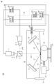
- FIG. 1 is a diagram showing an example of a configuration of a visual inspection system according to a first embodiment
- FIG. FIG. 3 is a diagram showing an example of a timing chart of control according to the first embodiment.
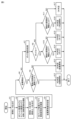
- 7 is a flowchart showing the procedure of inspection processing according to the first embodiment.
- 7 is a flowchart of metal foreign object identification processing according to Embodiment 1.
- FIG. 3 is a diagram illustrating difference processing between an ND filter image and a PL filter image according to the first embodiment.
- 7 is a flowchart of void identification processing according to the first embodiment.
- FIG. 3 is a diagram illustrating reflection of irradiation light from floating foreign objects according to Embodiment 1.
- FIG. 3 is a diagram illustrating reflection of irradiation light from a void according to the first embodiment.
- FIG. 3 is a diagram showing feature amounts used in the inspection according to the first embodiment.
- FIG. 3 is a diagram showing an example of outputting test results according to the first embodiment.
- 3 is a diagram illustrating an example of the configuration of a visual inspection system according to a second embodiment.
- FIG. 7 is a flowchart of a process for identifying metal foreign objects according to the first embodiment. 7 is a flowchart of a process for identifying voids according to the first embodiment. It is a figure which shows an example of the image of a defect and a blob. It is a figure which shows an example of the image of a blob.
- FIG. 7 is a diagram illustrating an example of the configuration of a visual inspection system according to a third embodiment.
- 3 is a diagram showing the configuration of a learning device 190 according to Embodiment 3.
- FIG. 2 is a diagram illustrating unsupervised learning using an autoencoder.
- 12 is a flowchart showing learning processing in Embodiment 3.
- 3 is a diagram showing the configuration of an inference device 221 according to Embodiment 3.
- FIG. 12 is a flowchart showing inference processing in Embodiment 3.
- FIG. 2 is a diagram showing an example of the configuration of a neural network.
- FIG. 1 is a diagram showing the configuration of a visual inspection system according to the first embodiment.
- Visual inspection system 100 inspects defects on the surface of object 20 to be inspected.
- the object 20 is not particularly limited as long as it is an object that specularly reflects light on its surface. In specular reflection, the incident angle and reflection angle of the emitted light are equal. Diffuse light is light that is scattered and reflected in all directions.
- the object 20 is, for example, a plastic molded product whose surface is coated with epoxy resin.
- the surface of the object 20 (surface to be inspected) may be a flat surface or a curved surface.
- the types of defects that can be detected by the visual inspection system 100 include metal foreign objects, floating foreign objects, and voids.
- the metal foreign object is an object that is embedded in the surface of the object 20 and has a flat shape.
- the metal foreign matter includes, for example, copper, aluminum, and the like.
- the floating foreign matter is an object that is attached to the surface of the object 20 and has an uneven shape.
- Floating foreign matter includes, for example, dust, fiber foreign matter, and the like.
- Voids include, for example, depressions (chips) that occur on the surface due to poor molding.
- the visual inspection system 100 in FIG. 1 includes a camera unit that photographs the surface of an object 20 and generates an image, an illumination unit that irradiates the surface of the object 20 with light, and an image that is generated by photographing the surface of the object 20.
- a processing unit that inspects the presence or absence of defects on the surface of the object 20 based on the captured image; a beam splitter 7; a drive shaft 22; a motor 21 to which the drive shaft 22 is connected; a jig 23; It includes a power supply device 24, polarizing plates 9 and 11, and a computer 30 having a control section 35 and an inspection processing section 32.
- the inspection processing section 32 constitutes a processing unit that inspects the presence or absence of defects on the surface of the object 20 based on an image generated by capturing the surface of the object 20.
- the processing unit constituted by the inspection processing section 32 includes a first processing unit that provides image processing for inspecting the presence of voids or floating foreign matter on the surface, and a first processing unit that provides image processing for inspecting the presence of metallic foreign matter on the surface. and a second processing unit for providing.
- the motor 21 is a power device that converts electrical energy into mechanical energy, and in this embodiment, a DC pulse voltage is applied via a driver to output rotational motion.
- the drive shaft 22 is a rotation shaft that transmits the rotational driving force of the motor 21 to the object 20.
- the jig 23 supports the object 20 set on the jig 23 so that the outer peripheral surface, which will be described later, is placed within the imaging field of the camera unit.
- the power supply device 24 supplies power to the lighting unit.
- the object 20 has a cylindrical shape, and a defect inspection is performed on the outer peripheral surface (surface) exposed to the outside of the object 20.
- the object 20 has an axis passing through the center of a circle whose circumference is the circumference of the outer peripheral surface and extending in the longitudinal direction of the cylinder. By connecting this shaft to the drive shaft 22, the shaft rotates in conjunction with the rotation of the motor 21. As the axis rotates, the object 20 rotates concentrically with respect to the center of the circle.
- the cylindrical shape indicating the shape of the object 20 to be inspected is a concept that includes a substantially cylindrical shape, and the cylindrical shape also includes a hollow cylindrical shape.
- the shape of the object 20 is not limited to a cylindrical shape, and the surface of the object 20 to be inspected may be stationary without rotating during the visual inspection.
- the control unit 35 includes a camera control unit 31 that controls the camera unit, an illumination control unit 33 that controls the illumination unit to irradiate the illumination light onto at least the imaging field of the camera unit on the surface of the object 20, and a motor control unit.
- the inspection processing unit 32 performs inspection processing based on images captured and generated by the camera unit.
- the image generated and output from the camera unit constitutes, for example, image data in units of frames.
- the inspection processing performed by the inspection processing section 32 includes image processing on images from the camera unit.
- the motor control unit 34 outputs a number of pulse signals according to the step angle corresponding to the rotation amount (rotation angle and rotation speed) of the motor 21.
- the motor 21 is composed of a general stepping motor or a servo motor.
- the motor 21 has an ON/OFF cycle of a pulse signal as one pulse, and when one pulse signal is output, it rotates by one step angle, and the drive shaft 22 rotates in conjunction with the rotation.
- the motor control unit 34 outputs pulse signals for the number of pulses corresponding to the amount of rotation, it outputs a positioning completion signal. In this embodiment, when one pulse signal is output, a positioning completion signal is output.
- the lighting control section 33 is connected to the lighting unit and the power supply device 24, and controls turning on and off of the lighting unit, as well as controlling the intensity of the emitted light.
- the control unit 35 synchronizes the trigger signal output from the camera control unit 31, the lighting and extinguishing control signal output from the illumination control unit 33, and the pulse signal output from the motor control unit 34.
- a trigger signal is output for each step angle, and an image captured by the camera unit is generated.
- a trigger signal instructing the camera unit to take an image is output for each step angle, but the output interval of the trigger signal is not limited to each step.
- the camera unit includes a first camera 1 and a second camera 4.
- the first camera 1 and the second camera 4 each include a line sensor so as to be able to image a line-shaped inspection area 61, which will be described later.
- a line sensor is configured by arranging solid-state image sensors such as CCDs (Charge Coupled Devices) and photodiodes.
- the line sensor is not limited to one for monochrome imaging, but may be one for color imaging.
- the first camera 1 and the second camera 4 each receive light incident on the image sensor and output an electrical signal according to the amount of light received. An image is generated based on electrical signals output from the image sensor.
- the illumination unit includes a first illumination unit and a second illumination unit that constitute a light source for illuminating the surface of the object 20 to be imaged by the camera unit by irradiating the surface with illumination light.
- the first lighting unit includes a lighting device 12 and a lighting device 13
- the second lighting unit includes a lighting device 8 and a lighting device 10.
- Each lighting device includes a long line-shaped LED (Light Emitting Diode) so as to be able to irradiate an inspection area on a surface extending in a longitudinal direction parallel to the axis of the object 20 with diffused light. Including equipment.
- the computer 30 can be configured to include a processor circuit (processing circuit) having an arithmetic circuit, such as a personal computer, a microcomputer board, an ASIC (Application Specific Integrated Circuit), or an FPGA (Field Programmable Gate Array).
- the computer 30 may implement each part described above as a module provided by such a processor circuit executing a program, or a part or all of the functions provided by these modules may be implemented as a dedicated module. It may be implemented using other hardware circuits (eg, ASIC or FPGA).
- the illumination devices 8 and 10 adjust the brightness when imaging the surface of the object 20.
- the illumination devices 8 and 10 respectively irradiate the surface of the object 20 with irradiation lights L1 and L2 having only predetermined polarization angle components.
- Illumination devices 8 and 10 include polarizing plates 9 and 11, respectively. Polarizing plates 9 and 11 emit only light having only a predetermined polarization angle component among the light components irradiated from illumination devices 8 and 10, respectively.
- Irradiation lights L1 and L2 having only predetermined polarization angle components are irradiated onto the surface of the object 20.
- specularly reflected light LA1 is generated and enters the beam splitter 7.
- the beam splitter 7 is a cube-shaped beam splitter composed of two right-angled prisms.
- the beam splitter 7 is arranged in a direction in which the irradiated lights L1 and L2 are specularly reflected.
- the beam splitter 7 splits the incident light into two lights at a predetermined splitting ratio.
- the reflected light LA1 incident on the beam splitter 7 is split into reflected light LA2 and reflected light LA3.
- the reflected light LA2 is incident on the first camera 1.
- the reflected light LA3 is incident on the second camera 4.
- the first camera 1 and the second camera 4 simultaneously image the surface of the object 20.
- the first camera 1 images the surface of the object 20 from the direction of specular reflection of the irradiation light L1.
- the first camera 1 receives the reflected light LA2, captures an image of the surface of the object 20, and generates an image of the surface of the object 20.
- the first camera 1 includes a lens 2 and an ND (Neutral Density) filter 3 to which the lens 2 is attached.
- the ND filter 3 is also called a "neutral density filter" and reduces the amount of light by a certain amount over the entire predetermined wavelength band.
- the image generated by the light that has passed through the ND filter 3 will be referred to as an ND filter image.
- the light passing through the ND filter 3 includes light reflected from a flat metal foreign object embedded in the surface of the object 20 and light reflected from a floating foreign object.
- the lens 2 condenses the light that has passed through the ND filter 3 and forms an image at one point.
- the first camera 1 having the ND filter 3 images the surface of the object 20 and generates an ND filter image.
- the ND filter image is generated by light reflected from an embedded flat metal foreign object on the surface of the object 20 and light reflected from a floating foreign object.
- the second camera 4 images the surface of the object 20 from a direction perpendicular to the specular reflection direction of the irradiation light L1.
- the second camera 4 receives the reflected light LA3, captures an image of the surface of the object 20, and generates an image of the object 20.
- the second camera 4 includes a lens 5 and a PL (Polarized Light) filter 6 to which the lens 5 is attached.
- the PL filter 6 is also called a "polarizing filter” and is a lens filter that uses a polarizing film.
- a polarizing filter has a structure in which a polarizing film is sandwiched between two pieces of glass, and includes a rotating frame structure for rotating the direction of the polarizing film.
- the polarizing film of the PL filter 6 is mounted so that the direction of the polarizing film is perpendicular to the direction of polarization of light reflected from a foreign metal object embedded in the surface of the object 20.
- the lens 5 condenses the light that has passed through the PL filter 6 and forms an image at one point.
- the image generated by the light that has passed through the PL filter 6 will be referred to as a PL filter image.
- the polarization characteristics of incident light and reflected light are preserved as they are. It is known that reflected light from dust and fiber foreign matter having minute scattering particles becomes unpolarized light. Since the polarization direction of the light condensed by the lens 5 is perpendicular to the light reflected from the metal foreign object, if there is a flat metal foreign object embedded in the surface of the object 20, that part will appear dark. On the other hand, if there is a floating foreign substance having irregularities on the surface of the object 20, that part will appear bright.
- the light passing through the ND filter 3 includes light reflected from buried flat metal foreign matter, floating foreign matter, and voids present on the surface of the object 20.
- the light transmitted through the PL filter 6 does not include the light reflected from the metallic foreign matter blocked by the PL filter 6, but includes only the light reflected from the floating foreign matter or voids.
- the metallic foreign matter, floating foreign matter, and voids are brightly emphasized in the ND filter image, and in the PL filter image, Only floating foreign objects and voids are highlighted brightly. Therefore, the presence or absence of a metal foreign object can be identified based on a difference image showing the difference between the ND filter image and the PL filter image, which is obtained by comparing the two images. In this embodiment, since the ND filter image and the PL filter image can be generated simultaneously, the time required for the visual inspection can be reduced compared to the case where the images are generated separately.
- the illumination devices 12 and 13 irradiate the surface of the object 20 with imaging light for identifying whether a defect is a void.
- the illumination devices 12 and 13 emit light having different wavelengths for void identification processing to be described later.
- the illumination devices 12 and 13 irradiate the surface of the object 20 with irradiation lights L3 and L4.
- irradiation lights L3 and L4 When the irradiation lights L3 and L4 are incident on the surface of the object 20, a specular reflected light LA1 is generated from the surface, and the reflected light LA1 is incident on the beam splitter 7.
- the reflected light LA1 incident on the beam splitter 7 is split into reflected light LA2 and reflected light LA3, which are focused on the lenses 2 and 5, respectively.
- the reflected light LA2 is incident on the first camera 1 via the lens 2, and the first camera 1 generates an image based on the reflected light LA2.
- the reflected light LA3 is incident on the second camera 4 via the lens 5, and the second camera generates an image based on the reflected light LA2.
- the illumination devices 12 and 13 respectively irradiate the surface of the object 20 with irradiation lights L3 and L4 from horizontal and different directions.
- This horizontal also includes the concept of approximately horizontal.
- the irradiation lights L3 and L4 that are irradiated horizontally to the surface in this way are applied to the portion of the surface of the object 20 where the void is formed. It is not reflected in other parts where voids are not formed. Therefore, in the state where the irradiation lights L3 and L4 are irradiated, the reflected light LA1 includes the reflected light in the portion where the void is formed, and the reflected light in other portions is attenuated.
- the images generated by the first camera 1 and the second camera 4 have excellent contrast between the portion of the surface of the object 20 where the void is formed and the other portions. Even if the images captured and generated by the first camera 1 and the second camera 4 in a state where the illumination lights are irradiated from the illumination devices 12 and 13 are an ND filter image and a PL image, these images also have The excellent contrast described above can be obtained. Note that the ND filter 3 attenuates bands other than the wavelengths of the irradiated lights L3 and L4.
- the surface in the configuration for detecting metal foreign objects, is imaged with the illumination light from the illumination device 8 equipped with the polarizing plate 9 and the illumination device 10 equipped with the polarizing plate 11, whereas voids are detected.
- the surface is imaged with the illumination light from the illumination devices 12 and 13 to which no polarizing plate is attached. In this way, identification of the presence or absence of metallic foreign objects and identification of the presence or absence of voids are performed based on images generated by imaging under illumination conditions (irradiation angle and polarization) adapted to each.
- the illumination devices 8 and 10 equipped with the polarizing plates 9 and 11 emit a first irradiation light having a first wavelength and a second irradiation light having a second wavelength with respect to the surface of the object 20 horizontally from different directions. It is also possible to irradiate the irradiation light of step 2 and identify metal foreign objects and voids using the captured image.
- FIG. 2 is a diagram showing an example of a timing chart of control according to the first embodiment.
- the horizontal axis shows the passage of time and also shows the control cycle CY.
- a control signal for controlling lighting (ON) and extinguishing (OFF) of the lighting devices 8, 10, 12, and 13 and a control signal for controlling the lighting devices 8, 10, 12, and 13, A trigger signal that instructs imaging, a motor pulse signal that rotates the motor 21 by one step angle, and a positioning completion signal are shown.
- the object 20 is set on the jig 23 in advance, and the lighting devices 8, 10, 12, and 13 are in the off state as an initial state.
- the first control cycle CY is started at time T0.
- no motor pulse signal is output, and a lighting control signal is output to the lighting devices 8 and 10 at timing (a).
- a trigger signal is then output to the first camera 1 and the second camera 4.
- the first camera 1 and the second camera 4 take an image of the surface in response to the trigger signal and output the image. .
- a control signal for turning on is output to the lighting devices 12 and 13, and a control signal for turning off the light is output to the lighting devices 8 and 10.
- the lighting devices 8 and 10 are turned off and the lighting devices 12 and 13 are turned on
- a trigger signal is output to the first camera 1 and the second camera 4.
- the first camera 1 and the second camera 4 take an image of the surface in response to the trigger signal and output the image. do.
- a control signal to turn off the lights is output to the lighting devices 12 and 13, and the lighting devices 12 and 13 turn off in response to the control signal.
- a pulse signal is output at timing (e) at the start of the control cycle, and the motor 21 rotates in response to the pulse signal and is linked to the rotation.
- the inspection area located in the imaging field of view on the surface of the object 20 is then switched.
- a positioning completion signal is output at timing (e) when the rotation of the motor 21 ends.
- a lighting control signal is output to the lighting devices 8 and 10 at a subsequent timing (f).
- the illumination devices 8 and 10 turn on in response to the control signal and emit light, and then a trigger signal is output to the first camera 1 and the second camera 4 at timing (g).
- the first camera 1 and the second camera 4 capture an image of the surface in response to the trigger signal and output an image.
- a control signal for turning on is output to the lighting devices 12 and 13, and a control signal for turning off the light is output to the lighting devices 8 and 10.
- the lighting devices 8 and 10 are turned off and the lighting devices 12 and 13 are turned on, and at subsequent timing (i), a trigger signal is output to the first camera 1 and the second camera 4. .
- the first camera 1 and the second camera 4 take an image of the surface in response to the trigger signal and output the image. do.
- a control signal to turn off the lights is output to the lighting devices 12 and 13, and the lighting devices 12 and 13 turn off in response to the control signals.
- the trigger signal from the camera control section 31, the control signal for turning on and off from the lighting control section 33, and the pulse signal from the motor control section 34 are output in synchronization with each other.
- the inspection area is imaged at every step angle and an image is output.
- FIG. 3 is a flowchart showing the procedure of inspection processing according to the first embodiment.
- the flowchart of FIG. 3 shows, for example, processing for images for each step angle acquired in each control period CY of FIG. 2.
- FIG. 4 is a flowchart of metal foreign object identification processing according to the first embodiment.
- FIG. 5 is a diagram illustrating the difference processing between the ND filter image and the PL filter image according to the first embodiment.
- FIG. 6 is a flowchart of void identification processing according to the first embodiment.
- FIG. 7 is a diagram illustrating reflection of irradiation light from floating foreign objects according to the first embodiment.
- FIG. 8 is a diagram illustrating reflection of irradiation light from a void according to the first embodiment.
- step A1 of FIG. 3 the lighting control unit 33 turns on the lighting devices 8 and 10.
- step A2 the camera control section 31 outputs a trigger signal to the first camera 1 and the second camera 4.
- the surface of the object 20 is simultaneously captured by the first camera 1 and the second camera 4, and an ND filter image and a PL filter image are output.
- step A3 the lighting control unit 33 turns off the lighting devices 8 and 10, and turns on the lighting devices 12 and 13.
- step A4 the camera control unit 31 outputs a trigger signal to the first camera 1. Thereby, the surface of the object 20 is imaged by the first camera 1, and an ND filter image is output.
- a trigger signal is output to at least the first camera 1 or the second camera 4, and the surface of the object irradiated with the irradiation light from the first illumination unit is imaged.
- images that can be used for void identification processing are not limited to ND filter images, but may also be PL filter images that are captured and generated by the second camera 4, and may also include ND filter images and PL filter images. Both may be used as images for void identification processing.
- the ND filter image Since the PL filter image according to this embodiment has a characteristic that the brightness of the entire image is lower than that of the ND filter image, the ND filter image is acquired in step A4. Even if the ND filter image includes a partial image of the metal foreign object, the position information indicating the position of the partial image of the metal foreign object in the ND filter image should be obtained from the difference image indicating the difference between the ND filter image and the PL filter image. Can be done. Therefore, the partial image of the metal foreign object can be detected and excluded from the ND filter image using the position information.
- step A5 the second processing unit of the inspection processing section 32 performs the foreign metal identification process shown in FIG. 3.
- step A5-1 of FIG. 3 the inspection processing unit 32 performs differential processing using the ND filter image output from the first camera 1 and the PL filter image output from the second camera 4 in step A2. Execute and generate a difference image.
- ND filter image 300 includes partial images of metal foreign matter W1 and floating foreign matter W2, and PL filter image 301 includes a partial image of floating foreign matter W2.
- the pixel values of the PL filter image are subtracted from the pixel values of the ND filter image, and the result indicates the pixel value of the difference image 302.
- the difference image 302 of FIG. 5 only a partial image of the metal foreign object W1 remains.
- step A5-2 the inspection processing unit 32 generates a binarized image by binarizing the pixel values of the difference image using a predetermined binarization threshold.
- the inspection processing unit 32 sets the pixel value to "1" when the value of the pixel of the difference image is equal to or higher than the binarization threshold, and sets the value of the pixel to "1" when the value of the pixel of the difference image is less than the binarization threshold. sets the value of that pixel to "0".
- step A5-3 the inspection processing unit 32 performs labeling processing on the binarized image.
- labeling processing is a process of classifying multiple regions in a binarized image as a group by adding the same label "1" to connected pixels in the binarized image, and is a process known in the field of image processing. technology, so detailed explanation will not be repeated.
- step A6 the second processing unit of the inspection processing section 32 determines whether the surface of the object 20 contains a metal foreign substance based on the partial image of the metal foreign substance included in the difference image described above. Determine whether More specifically, the inspection processing unit 32 determines, for each region, one or more regions formed by a plurality of pixels labeled with “1” in the partial image of the metal foreign object in the difference image. Measure the area of .
- the inspection processing unit 32 determines that there is a region whose area is equal to or greater than the threshold value (YES at step A6), the inspection processing unit 32 moves to the processing from step A9 onwards for evaluating metal foreign objects, and determines that there is no region whose area is equal to or greater than the threshold value. If it is determined that this is the case (NO in step A6), the process proceeds to step A7, which identifies voids.
- step A7 the first processing unit of the inspection processing section 32 performs a process of identifying voids using the ND filter image acquired in step A4.
- the inspection processing unit 32 extracts color information specific to voids or floating foreign objects from the ND filter image.
- the color of an image indicates the gradation value of each pixel that makes up the image.
- the illumination devices 12 and 13 each emit light of different wavelengths (different colors), so depending on the relationship between the color of the ND filter image and the direction in which the light is irradiated, foreign matter may be void or floating. Foreign objects are identified. An identification method based on such a relationship will be explained with reference to FIGS. 7 and 8. 7 and 8, the first camera 1 and illumination devices 12 and 13 of the visual inspection system 100 of FIG. 1 are shown, and other components are omitted for simplicity of explanation. ing.
- FIG. 7 shows a case where the floating foreign matter P6 on the surface of the object 20 is irradiated with irradiation lights of different wavelengths from different directions horizontally to the surface.
- FIG. 8 shows a case in which a void P7 formed on the surface of the object 20 is irradiated with irradiation lights of different wavelengths from different directions parallel to the surface.
- irradiation lights L3 and L4 having different wavelengths are irradiated from the left and right sides of the first camera 1, respectively.
- the irradiation light L3 is reflected on the left surface of the floating foreign object P6, the reflected light LA(3) on the left surface is incident on the first camera 1, and the irradiation light L4 is reflected on the right surface of the floating foreign object P6, The reflected light LA(4) on the right surface enters the first camera 1.
- the irradiated light L3 is reflected at the right surface of the void P7, and its reflected light LA(3) is incident on the camera 1
- the irradiated light L4 is reflected at the left surface of the void P7, and its reflected light LA(3) (4) is incident on camera 1.
- the irradiation lights LA(3) and LA(4) are directed to the left and right sides of the array surface of the image sensor of the first camera 1, respectively. enter the position.
- the irradiation lights LA(3) and LA(4) are incident on the right and left positions on the array surface of the image sensor, respectively. In this way, the positions at which the reflected light is incident on the array surface of the image sensor are switched between the left and right sides.
- the wavelength (color) of the reflected light LA(3) there is a difference in the wavelength (color) of the reflected light LA(3) between the ND filter image generated by capturing the floating foreign object P6 in FIG. 7 and the ND filter image generated by capturing the void P7 in FIG.
- the arrangement of the partial image and the wavelength (color) of the reflected light LA(4) are different.
- the model image showing the color arrangement pattern of the floating foreign matter P6 is called a pattern C1
- the model image showing the color arrangement pattern of the void P7 is called a pattern C2.
- step A7-1 the inspection processing unit 32 compares the ND filter image with the pattern C2, and determines whether the partial image of the void P7 is included in the ND filter image based on the comparison result. More specifically, the inspection processing unit 32 scans the ND filter image with the pattern C2, and identifies whether or not a partial image indicating the color arrangement of the void P7 is included based on the scan result. The inspection processing unit 32 also compares the ND filter image with the pattern C1, and determines whether the ND filter image includes a partial image of the floating foreign object P6 based on the comparison result. More specifically, the inspection processing unit 32 scans the ND filter image with the pattern C1, and identifies whether or not a partial image indicating the color arrangement of the floating foreign matter P6 is included based on the scan result. These identification results are output as color information.
- step A7-2 the inspection processing unit 32 converts the ND filter image into a grayscale image, and generates a binarized image from the grayscale image using a predetermined binarization threshold.
- step A7-3 the inspection processing unit 32 performs labeling processing on the binarized image.
- labeling processing classifies a plurality of regions as a group by adding the same label "1" to connected pixels in a binarized image, similar to the method described above.
- step A7-4 the inspection processing unit 32 compares the labeling processing information obtained from the ND filter image in steps A7-2 and A7-3 with a predetermined pattern C3 indicating the shape characteristics of the void. , Based on the matching results, it is determined whether the ND filter image includes a partial image representing a shape characteristic of the void.
- Pattern C3 includes a model image showing the characteristics of the shape of such a void.
- step A7 it is determined from the color information and shape characteristics whether or not the ND filter image includes a void partial image.
- void identification uses the logical sum of the judgment result based on color information and the judgment result based on shape characteristics, but is not limited to the logical sum, and other judgment conditions such as logical product may also be used. good.
- step A8 the inspection processing unit 32 determines whether the ND filter image includes a void partial image based on the processing result of step A7. If it is determined that a partial image of a void is included (YES in step A8), the inspection processing unit 32 performs the void determination process from step A10 onwards, and determines that a partial image of a void is not included. If so (NO in step A8), the inspection processing unit 32 executes the floating foreign object determination process from step A11 onwards.
- the inspection processing unit 32 determines whether the area of the foreign object is greater than or equal to a predetermined threshold value. More specifically, the inspection processing unit 32 measures the area of each region formed by a plurality of pixels to which the same label is added in the ND filter image. Then, it is determined whether the measurement result is greater than or equal to a predetermined threshold value.
- area is used as a feature quantity for determination, but depending on the inspection standard, different feature quantities such as main axis length, minor axis length, circumference length, etc. may be used for determination.
- FIG. 9 is a diagram showing feature amounts used in the inspection according to the first embodiment. It is assumed that a partial image of an identified defect such as a metal foreign object, a floating foreign object, or a void has the shape of the shaded area in FIG. 9 .
- the inspection processing unit 32 sets a rectangle circumscribing such a partial image. In FIG. 9, a circumscribed rectangle having, for example, 4 ⁇ 4 pixels is set.
- the feature values of a partial image of such a defect include the area S of the partial image based on the size of the circumscribed rectangle, the principal axis length L indicating the longitudinal length of the partial image based on the size of the circumscribed rectangle, and the size of the circumscribed rectangle.
- the sub-axis length W indicates the length of the partial image in the lateral direction based on the size of the circumscribed rectangle
- the peripheral length CL indicates the circumferential length of the partial image based on the size of the circumscribed rectangle.
- step A12 determines in step A9 of FIG. (step A12), and if it is determined that the area value is not equal to or greater than the threshold value (NO in step A9), an OK determination indicating that no metal foreign matter has been detected on the surface of the object 20 is output ( Step A13). Further, when the inspection processing unit 32 determines that the area value of the partial image is equal to or greater than the threshold value in step A10 of FIG. 3 (YES in step A10), this indicates that a void has been detected on the surface of the object 20.
- Step A14 It outputs an NG determination (step A14), and if it determines that the area value is not equal to or greater than the threshold value (NO in step A10), it outputs an OK determination indicating that no voids have been detected on the surface of the object 20 ( Step A15). Further, if the inspection processing unit 32 determines in step A11 of FIG. If it is determined that the area value is not equal to or greater than the threshold value (NO in step A11), no defects (metallic foreign matter, voids, floating foreign matter) are detected on the surface of the object 20. A determination of OK is output indicating that this is the case (step A17).
- defects on the surface of the object 20 are detected due to differences in reflection characteristics of irradiation light based on differences between metals and non-metals, and differences in shapes of floating foreign objects and voids.
- differences in the reflection characteristics of irradiated light it is possible to identify the presence or absence and type of defects without complicating the camera unit.
- the visual inspection system 100 includes both a configuration for identifying the presence or absence of voids or floating foreign objects and a configuration for identifying metal foreign objects, but may include only one of the configurations.
- FIG. 10 is a diagram showing an example of outputting test results according to the first embodiment.
- test results are displayed in windows 70, 71, 72, 73, and 74.
- the window 70 displays an object 60, which is an image schematically showing the outer peripheral surface of the cylindrical object 20, and an object showing a line-shaped inspection area 61 in the object 60.
- the window 72 displays information 57 indicating the feature amount used for identification and its threshold value for each defect to be identified (metal foreign matter, floating foreign matter, void).
- an object 50 indicating the processing result of the visual inspection is displayed.
- the object 50 shows the entire outer peripheral surface of the object 20 by combining a plurality of inspection areas 61. Defects detected during inspection are shown overlaid on object 50 as object 51 .
- the window 74 shows the type of defect and determination value for the object 51 shown in the window 71.
- the defect identifier 56 for each object 51 shown in the window 71, the defect identifier 56, the defect type 55, the defect determination 54, the feature amount 53 of the defect, and the defect position 52 of the object 51 are displayed. shown.
- the determination 54 indicates the determination value in any of steps A12 to A17 in FIG. 3 for the partial image of the defect.
- the position 52 means that the detected position on the surface of the defect is the coordinate position (XY coordinate values).
- the XY coordinate position of the partial image in the image of the inspection area 61 is also detected.
- the X-coordinate position of the inspection area 61 is calculated based on the number of pulse signals output from the start of the visual inspection of the object 20. be done.
- the inspection processing unit 32 determines the coordinate position of the defect object 51 based on a predetermined calculation based on the XY coordinate position of the defect in the inspection area 61 and the X coordinate position on the outer peripheral surface (surface) of the inspection area 61.
- the position 52 is calculated.
- the visual inspection system 100 includes an object window 71 in which an object 51 indicating a detected defect is overlaid on an object 50 indicating the surface of the object 20, so that the user can monitor the inspection results. and an object indicating the type 55 or position 52 of the object are displayed on the display 1003 in association with each other.
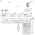
- FIG. 11 is a diagram illustrating an example of the configuration of a visual inspection system according to the second embodiment.
- visual inspection system 1000 includes a computer 30 and a server 40 that communicates with computer 30.
- the computer 30 includes a processor 1001 , a memory 1002 , a display 1003 , a keyboard 1005 , a memory card interface 1004 to which a memory card 1007 is removably attached, and an HDD (Hard Disk Driver) 1006 connected by a bus 1008 .
- HDD Hard Disk Driver
- the processor 1001 implements the visual inspection process shown in FIG. 3 by expanding the program stored in the HDD 1006 into the memory 1002 and executing it.
- the HDD 1006 stores system programs including an OS (Operating System) 120, application programs, and data.
- the data includes test data 124 indicating test results and pattern information 125 having patterns C1, C2, and C3.
- the application program includes a control program 121 that realizes the control unit 35 when executed, an inspection program 122 that realizes the inspection processing unit 32 when executed, and a UI (User Interface) program 123.
- the UI program 123 When executed, the UI program 123 outputs information regarding visual inspection to the user and provides a UI tool that accepts user operations on the computer 30.
- the information in FIG. 10 is displayed on the display 1003 by the UI tool.
- the computer 30 includes both the control unit 35 and the test processing unit 32, but the test processing unit 32 may be implemented in a device external to the computer 30, such as the server 40 in FIG. 11.
- the server 40 includes an on-premises server configured with a general-purpose computer or a server on a cloud.
- the computer 30 transfers the image received from the camera unit to the server 40 via the communication interface 1009 and the network 310.
- the server 40 executes the visual inspection process shown in FIG. 3 on the image received from the computer 30, and transfers the execution result to the computer 30 as, for example, Web page information.
- the web browser of the computer 30 causes the display 1003 to display, for example, the screen shown in FIG. 10 based on the web page transferred from the server 40. Further, the screen shown in FIG. 10 showing the results of the inspection process may be displayed on a display (not shown) included in the server 40.
- FIG. 12 is a flowchart of a process for identifying metal foreign objects according to the first embodiment.
- the inspection processing unit 32 performs the foreign metal identification process shown in the flowchart of FIG.
- the inspection processing section 32 may further include a processing unit that performs identification based on the color components described above.
- this processing unit generates an ND filter image and a PL filter image generated by capturing an image of the surface of the object 20 irradiated with light of a predetermined wavelength from the second illumination unit.
- This predetermined wavelength includes a wavelength of light corresponding to the color component of the surface of the object 20.
- step A12-0 of FIG. 12 the inspection processing unit 32 acquires the ND filter image output from the first camera 1 and the PL filter image output from the second camera 4.
- the inspection processing unit 32 extracts only a predetermined color component of RGB, that is, the red (R) component, from the PL filter image. For example, the inspection processing unit 32 scans the PL filter image using pixel values indicating predetermined color components, and based on the scan results, generates a partial image composed of pixels of the red (R) component from the PL filter image. Extract only.
- a predetermined color component of RGB that is, the red (R) component
- step A12-9 the inspection processing unit 32 performs filter processing on the extracted partial image of the red component in order to emphasize this partial image, and in step A12-10, converts the filtered partial image into a binary image.
- the inspection processing unit 32 scans a partial image using a predetermined pixel value as a threshold, and extracts a portion exceeding the threshold from the binarized partial image.
- This threshold value corresponds to a pixel value for extracting a partial image of a metal foreign object embedded in the surface of the object 20.
- step A12-11 the inspection processing unit 32 performs labeling processing on the binarized partial image.
- step A12-12 the inspection processing unit 32 performs size determination for each of the different regions to which the same label is attached in the partial image through the labeling process. Each region with the same label corresponds to a blob corresponding to a metal. A blob indicates a collection of pixels having the same density (pixel value).
- the inspection processing unit 32 detects the area of each blob and the XY coordinate position of this blob in the partial image.
- step A12-13 the inspection processing unit 32 extracts the XY coordinate positions of one or more blobs whose size has been determined. Each of the extracted XY coordinate positions of one or more blobs indicates a candidate position of the metal foreign object in the partial image.
- the predetermined color component is not limited to red.
- the predetermined color components may be set according to the surface color of the object 20 to be inspected. In the process shown in FIG. 12, the surface of the object 20 is, for example, reddish brown. Therefore, the predetermined color component indicates a red (R) component, which is a color component that is easy to extract.
- the inspection processing unit 32 facilitates binarization by extracting a red component close to the color component of the surface of the object 20. More specifically, since the light reflected from the surface of the metal foreign object is attenuated by passing through the PL filter, the amount of light reflected from the surface is small and becomes dark. Focusing on this point, when the inspection processing unit 32 performs binarization on a partial image corresponding to a red component close to the surface color from the PL filter image, in the partial image after binarization, bright areas start to darken. The region can be easily extracted as a candidate position (XY coordinate position) of the embedded metal foreign object.
- the inspection processing unit 32 performs the above-described filter processing and binary processing on the ND filter image acquired in step A12-1 in step A12-1, step A12-3, step A12-4, and step A12-5. , labeling processing, size determination, and extraction of multiple candidate positions (XY coordinate positions). As a result of such processing, the XY coordinate position of each blob in the ND filter image is extracted for both brightly shining metallic blobs and non-metallic blobs.
- the inspection processing unit 32 detects the matching rate for each of the one or more candidate positions extracted in the PL filter image. More specifically, for each of one or more candidate positions extracted in the PL filter image, the inspection processing unit 32 converts the XY coordinate position of the candidate position into the XY coordinate position of each blob extracted in the ND filter image. Based on the comparison result, the coincidence rate of the XY coordinate values is calculated. For example, for each candidate position, the XY coordinate position of the candidate position is compared with the XY coordinate position of each blob extracted in the ND filter image. The result of the comparison indicates, for example, the XY coordinate position of the blob that is closest to the XY coordinate position of the candidate position.
- the match rate indicates, for example, a value based on the magnitude of the deviation between the XY coordinate position of the candidate position and the XY coordinate position of the blob indicating the closest position.
- the magnitude of the deviation is, for example, the distance between the XY coordinate position of the candidate position and the XY coordinate position of the blob indicating the closest position. The shorter the distance, the higher the matching rate.
- step A12-7 the inspection processing unit 32 compares the matching rate of the candidate position with a threshold value for each of the one or more candidate positions extracted in the PL filter image, and the comparison result is (matching rate>threshold value). , it is determined that the candidate position is a metal foreign object embedded in the surface.
- the inspection processing section 32 outputs the determination result. This output includes displaying the determination result, storing it in a storage medium, transferring it, etc. This determination result may include the determined XY coordinate position of the metal foreign object.
- the inspection processing unit 32 can identify defects on the surface of the object 20 (metallic foreign matter embedded in the surface) based on the color components of the PL filter image, and can identify the XY coordinate position of the metallic foreign matter. can be identified.
- the inspection processing unit 32 may identify whether a defect on the surface of the object 20 is a void based on the characteristics of an image formed by a difference in the wavelength of light irradiated to the defect.
- FIG. 13 is a flowchart of a process for identifying voids according to the first embodiment.
- the inspection processing unit 32 executes the processing shown in the flowchart of FIG. 13.
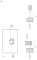
- FIG. 14 is a diagram showing an example of an image of defects and blobs.
- FIGS. 15, 16, and 17 are diagrams each showing an example of a blob image. For purposes of explanation, the images in FIGS. 15A, 16A, and 17A have in common the images in FIG. 14A.
- the irradiation light L3 is reflected on the right side of the depression, which is a defect, and the reflected light LA(3) is incident on the camera 1, and the irradiation light L4 is reflected on the left side of the void P7, and the reflected light LA(3) is reflected on the left side of the void P7.
- (4) is incident on camera 1. Since the irradiation light L3 and the irradiation light L4 have different wavelengths, the reflected light LA(3) and the reflected light LA(4) incident on the camera 1 also have different wavelengths. Therefore, in the configuration of FIG. 8, when the depression shown in (A) of FIG. 14 is imaged by the camera 1, in the captured image, the 2 Two images are detected.
- the inspection processing unit 32 Based on the positional relationship between the images of the “L3 blob” and “L4 blob” in the captured image, the inspection processing unit 32 detects the “L3 blob” and “L4 blob” when the positional relationship satisfies a predetermined condition. Identify (detect) voids consisting of "blobs".
- the inspection processing unit 32 acquires an image captured by the camera 1.
- the acquired image is a PL filter image or an ND filter image.
- the inspection processing unit 32 acquires the XY coordinate positions of the "L3 blob" image and "L4 blob” image in FIG. 14(B) in the image by scanning the image, and uses the acquired XY coordinates. Compare positions.
- the inspection processing unit 32 compares the Y coordinates of the two blobs in (A) of FIG. Specifically, the Y coordinate value of the center position of the "L4 blob" is compared with the upper and lower limits of the Y coordinate of the "L3 blob". Based on the comparison results, the inspection processing unit 32 determines that the condition that the Y coordinate value of the center position is between the upper and lower limits as shown in FIG. If the depression in (A) is determined to be a void candidate, and it is determined that the condition that the Y coordinate value of the center position is between the upper and lower limit values is not satisfied as shown in (C) in FIG. It is determined that the depression in (A) is not a void.
- step A13-2 regarding the two blobs in (A) of FIG. Search (scan) the image in the direction of the blob. More specifically, the inspection processing unit 32 searches in the X direction from the right end of the "L4 blob" to a distance corresponding to the principal axis length of the blob, and determines whether the condition for finding the "L3 blob" is met. judge whether As a result of the search, if the “L3 blob” is detected as shown in FIG. 16 (B) and it is determined that the conditions are satisfied, the inspection processing unit 32 determines that the depression shown in FIG. 14 (A) is a void candidate. However, when it is determined that the "L3 blob" cannot be detected and the conditions are not satisfied as shown in FIG. 16(C), it is determined that the depression shown in FIG. 14(A) is not a void.
- step A13-3 when the inspection processing unit 32 determines that the depression is a void candidate, in step A13-3, for the two blobs in (A) of FIG. Compare the X coordinates of Specifically, the left end X coordinate value of "L4 blob" is compared with the left end X coordinate value of "L3 blob", and based on the comparison result, the left end of "L4 blob” is "L3 blob". It is determined whether the condition of being to the left of the left edge of "Blob" is satisfied. When the inspection processing unit 32 determines that the condition that the left end of the "L4 blob" is on the left side of the "L3 blob" is satisfied as shown in FIG.
- the inspection processing unit 32 determines that the depression is a void. However, if it is determined that the left end of the "L4 blob" is not to the left of the left end of the "L3 blob" and the condition is not satisfied, as shown in FIG. 17(C), it is determined that the depression is not a void.
- the inspection processing unit 32 outputs the determination result of step A13-3. This output includes displaying the determination result, storing it in a storage medium, transferring it, and so on.
- FIG. 18 is a diagram illustrating an example of the configuration of a visual inspection system according to Embodiment 3.
- the visual inspection system 1000A of the third embodiment differs from the visual inspection system 1000 of FIG. 11 of the first embodiment in that the visual inspection system 1000A of the third embodiment includes a computer 30A instead of the computer 30. It is.
- the configuration of the visual inspection system 1000A other than the computer 30A is the same as the configuration shown in FIG. 11, so the description will not be repeated.
- the computer 30A is equipped with a device that collects learning data.
- the computer 30A collects learning data, performs learning to generate a learned model, and performs inference and testing using the learned model.
- the computer 30A includes, in the HDD 1006A, a learning program 131, an inference program 132, and an inference-based inspection program 133 in addition to the programs and data stored in the HDD 1006 in FIG.
- the learning program 131 configures the learning device 190 when executed.
- the learning device 190 acquires learning data using the inspection data 124 acquired using the rule base. More specifically, when the inspection process shown in FIG. The inspection result is obtained based on the image, the ND filter image, and the PL filter image and the ND filter image obtained under illumination light from the illumination device 12 and the illumination device 13). The inspection results are classified into one of four types: metal foreign matter, floating matter, void, and OK determination. By performing the inspection process in FIG. 3, inspection results according to the rule base are acquired, and inspection data 124 including the acquired inspection results is stored in the HDD 1006A.
- the inspection data 124 includes the four types of images described above and the inspection results corresponding to each image.
- the inspection result includes at least the defect type 55 (the type is any one of metal foreign matter, floating matter, void, and OK) determined for the corresponding image.
- Type 55 indicates a determination value in any one of steps A12 to A17 in FIG.
- the inspection data 124 includes a set of a PL filter image acquired under illumination light from the illumination device 8 and the illumination device 10 and an inspection result corresponding to the PL filter image, and a set of the inspection result corresponding to the PL filter image, the illumination device 8 and the illumination A set of an ND filter image acquired under illumination light from the device 10 and an inspection result corresponding to the ND filter image, and a PL filter image acquired under illumination light from the illumination device 12 and the illumination device 13. and a set of inspection results corresponding to the PL filter image, and a set of an ND filter image acquired under illumination light from the illumination device 12 and the illumination device 13 and an inspection result corresponding to the ND filter image. Since FIG.
- the determination values in steps A12 to A17 represent rule-based determination values (inspection results).
- the test processing unit 32 or the learning device 190 simultaneously performs an annotation operation in which a label indicating the type of judgment 55 included in the set is added to each set of the test data 124. Implemented.
- FIG. 19 is a diagram showing the configuration of a learning device 190 according to the third embodiment.
- the learning device 190 performs a learning process using learning data to obtain a learned model 134.
- the learning device 190 includes a data acquisition unit 193 that acquires an image 191 representing image data and a label 192 indicating a judgment value “OK” corresponding to this image 191, and a model generation unit 194 that generates a trained model 134. Be prepared.
- the image 191 is composed of four types of images (a PL filter image and an ND filter image obtained under illumination light from illumination device 8 and illumination device 10, and an image obtained under illumination light from illumination device 12 and illumination device 13).
- the data acquisition unit 193 acquires the image 191 by searching the inspection data 124 of the HDD 1006A for a set labeled "OK".
- the data acquisition unit 193 acquires the image data of the image 191 indicating the determination value "OK” as learning data.
- the image 191 indicating the determination value "OK” is not limited to one obtained by searching the inspection data 124 of the HDD 1006A.
- the data acquisition unit 193 uses a PL filter image obtained by imaging the surface of the object 20 (i.e., a non-defective product) free of defects (metallic foreign objects, floating objects, and voids) using a camera.
- an ND filter image may be acquired as the image 191.
- the model generation unit 194 generates a learned model 134 that reconstructs an image of a non-defective item from the image 191 of a non-defective item, which is the learning data acquired by the data acquisition unit 193 (non-defective learning). More specifically, when the learning data image 191 indicates a non-defective ND filter image, the model generation unit 194 generates a learned model 134 that reconstructs a non-defective ND filter image from the non-defective ND filter image. (good product learning), and when the image 191 of the learning data indicates a good product PL filter image, a trained model 134 that reconstructs a good product PL filter image from the good product PL filter image is generated (good product learning).
- a known algorithm such as supervised learning, unsupervised learning, or reinforcement learning can be used.
- supervised learning unsupervised learning
- reinforcement learning can be used.
- Embodiment 3 a case where a neural network learning algorithm is applied will be described as an example.
- the model generation unit 194 performs good quality learning by so-called unsupervised learning, for example, according to a neural network model.
- unsupervised learning only images 191 of non-defective products are given to the learning device 190 without linking data sets of results (labels) to inputs.
- the model generation unit 194 learns the feature amounts of the image 191 of a non-defective product and generates a learned model 134 that reconstructs an image of a non-defective product from the image 191 of a non-defective product.
- supervised learning refers to providing a set of input and result (label) data to the learning device 190, which learns the feature values in those learning data, and then learns the feature values in the training data and selects the features among the input results (labels).
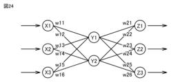
- FIG. 24 is a diagram showing an example of the configuration of a neural network.
- a neural network is composed of an input layer consisting of a plurality of neurons, an intermediate layer (hidden layer) consisting of a plurality of neurons, and an output layer consisting of a plurality of neurons.
- the intermediate layer includes one layer, or two or more layers.
- the input layer (X1 to Each input value after multiplication is accepted in the layer (Y1 to Y2), and each accepted input value (multiplication result) is further multiplied by weight W2 (w21 to w26) and output from the output layer (Z1 to Z3). Ru. This output result changes depending on the values of weights W1 and W2.
- the neural network learns the feature amount of the image 191 of a non-defective product by so-called unsupervised learning according to the image 191 of the non-defective product acquired by the data acquisition unit 193. That is, the neural network inputs the image 191 of a non-defective product into the input layer and sets the weights W1 and W2 so that the reconstructed image data output from the output layer approaches the image 191 of the non-defective product input into the input layer. Implement learning by adjusting.
- the model generation unit 194 generates and outputs the trained model 134 by performing the learning described above.
- the model generation unit 194 stores the learned model 134 in the HDD 1006A.
- the model generation unit 194 may perform learning according to a deep learning algorithm, such as a convolution processing (Convolution Neural Network) algorithm, which learns so as to be able to extract the feature amount itself.
- a convolution processing Convolution Neural Network
- the model generation unit 194 can use an autoencoder (self-encoder) as a learning algorithm.
- FIG. 20 is a diagram illustrating unsupervised learning using an autoencoder.
- the model generation unit 194 provides the autoencoder with only input data (image data of the image 191) that does not include a judgment value (label) as learning data.
- the autoencoder extracts feature quantities from input data, reconstructs (reproduces/builds) and outputs an image having feature quantities close to the extracted feature quantities.
- the autoencoder is an algorithm that reconstructs and outputs an image close to (almost the same as) the input image. Therefore, the reconstructed image is close to that of image 191.
- the autoencoder includes a first layer corresponding to the encoder 234 and a second layer corresponding to the decoder 245, and the encoder 234 and the decoder 245 constitute an integrated neural network.
- the encoder 234 extracts the feature amount from the image 191 of the non-defective product which is input data, and the decoder 245 reconstructs the image of the non-defective product from the feature amount.
- the encoder 234 includes an input layer and an intermediate layer of a neural network
- the decoder 245 includes an intermediate layer and an output layer of a neural network.
- the number of neurons in each layer of the encoder 234 decreases from 256 to 128 to 64 to 32
- the number of neurons in each layer of the decoder 245 increases from 32 to 64 to 128 to 256.
- the input data 212 is processed in the encoder 234 and then processed in the decoder 245 so that the input data 212 including a plurality of images 211 representing image data (corresponding to the image 191 of a good product) becomes the target data.
- the model generation unit 194 adjusts or learns the weights applied to the neural network so that the image data of each image 222 of the output data 223 that is close to each image 211 of the input data 212 is acquired, and An autoencoder, that is, a trained model 134, is generated.
- the data acquisition unit 193 acquires learning data created based on a combination of an image 191 of a non-defective product and an "OK" label 192 (a label of "OK” determined by the rule base), and
- the generation unit 194 performs unsupervised learning using the learning data.
- a neural network capable of outputting an image of a non-defective product that is close to the image 191 of a non-defective product, that is, an image of a non-defective product that can be determined as "OK" is learned.
- the image 191 of the non-defective product includes the four types of images of the non-defective product described above (the PL filter image and the ND filter image obtained under the illumination light from the lighting device 8 and the lighting device 10, and the and a PL filter image and an ND filter image acquired under illumination light from the illumination device 13). Therefore, when a learning algorithm is executed using each of these four types of images (images of non-defective products) as learning data, trained models corresponding to each of the four types of images are generated and stored in the HDD 1006A.
- FIG. 21 is a flowchart showing the learning process of the third embodiment.
- the data acquisition unit 193 acquires learning data. More specifically, the data acquisition unit 193 acquires learning data including a set of an image 191 of a non-defective object 20 and a label 192 with a rule-based determination value "OK".
- the image 191 and the label 192 indicating the determination result "OK" can be obtained in association with each other, for example, both may be obtained at the same time or at different timings.
- step b2 the model generation unit 194 performs so-called unsupervised learning using the learning data acquired by the data acquisition unit 193 to generate a trained model 134 that reconstructs an image of a good product from the image 191. do.
- step b3 the learning device 190 stores the generated learned model 134 in the HDD 1006A.
- the inference program 132 configures the inference device 221 when executed.
- FIG. 22 is a diagram showing the configuration of the inference device 221 according to the third embodiment.
- FIG. 22 shows an inspection unit 224 that performs an inspection based on an image 220 corresponding to the input and output of the inference device 221 and an image 222 representing a reconstructed image.
- the inference-based inspection program 133 configures the inspection unit 224 when executed.
- the HDD 1006A stores trained models corresponding to the above four types of images.
- the inference device 221 in FIG. 22 includes a data acquisition section 225, an inference section 226, and an inspection section 224.
- the data acquisition unit 225 acquires an image 220 obtained by photographing the surface of the object 20.
- the image 220 can be generated by the first camera 1 and the second camera 4 photographing the object 20, as in the first embodiment.
- the image 220 includes the above-mentioned four types of images (a PL filter image and an ND filter image obtained by photographing under the illumination light from the illumination device 8 and the illumination device 10, and the illumination device 12 and the illumination Data of either type of image (PL filter image and ND filter image) obtained by photographing under illumination light from the device 13 is shown.
- the type of image 220 is an ND filter image, but this inference process can be similarly applied even if the image 220 is any other type of image among the above four types of images.
- the inference unit 226 selects a trained model 134 corresponding to the image 220 (ND filter image) from among the four types of trained models 134 stored in the HDD 1006A from the image 220 of the object 20 acquired by the data acquisition unit 225. is used to reconstruct the image 220. That is, by inputting the image 220 (image data) of the object 20 acquired by the data acquisition unit 225 to this trained model 134, image data of a reconstructed image in which the ND filter image of the object 20 is reconstructed is generated. can do.
- the reconstructed image generated by the inference unit 226 is an image close to the ND filter image (good image) of the object 20 acquired by the data acquisition unit 225 and input to the autoencoder, Reconfiguration occurs properly. If the object 20 is not a non-defective item, the reconstructed image generated by the inference unit 226 will not be close to the image 220 (ND filter image) of the object 20 acquired by the data acquisition unit 225, and the reconstruction will fail. Not done properly. This is because the trained model 134 has been trained to reconstruct an image of a non-defective product from an image of a non-defective product.
- the inspection unit 224 shown in FIG. 22 performs a comparison process 227 that compares the image 222 of the reconstructed image of the object 20 output from the inference unit 226 with the image 220 of the object 20 input to the inference device 221 and the image data. Based on the result of the comparison process 227, it is inspected whether a defect exists on the surface of the object 20 corresponding to the image 220, and the inspection result is output to the display 1003 or the like.
- the inspection unit 224 can use a known algorithm such as Zscore or pattern matching for the comparison process 227, for example.
- the inference device 221 uses the model generated by the model generation unit 194 of the visual inspection system 1000 in which the inference device 221 is installed as the learned model 134; however, the learned model 134 is It may also be a trained model generated in another visual inspection system that inspects the object 20.
- FIG. 23 is a flowchart showing inference processing in the third embodiment.
- the inference device 221 executes the inference process shown in FIG. 23.
- the data acquisition unit 225 acquires an image 220 of the object 20.
- step c2 the inference unit 226 inputs the image 220 of the object 20 acquired by the data acquisition unit 225 to the learned model 134 stored in the HDD 1006A, and outputs the image 222 of the reconstructed image as the output of the learned model 134. get.
- step c3 the inference unit 226 outputs the obtained reconstructed image 222 to the inspection unit 224.
- the inspection unit 224 compares the image 220 of the object 20 acquired by the data acquisition unit 225 with the reconstructed image 222, and inspects whether the object 20 is a good product based on the comparison result. . More specifically, when the inspection unit 224 determines that the image 220 and the reconstructed image 222 are similar through pattern matching or the like, the inspection unit 224 determines that the object 20 to be inspected is on the surface. It can be determined that there are no defects (metallic foreign objects embedded in the surface, floating objects, and voids). When the inspection unit 224 determines, by pattern matching or the like, that the two images are not similar, it can determine that a defect exists on the surface of the object 20. The inspection unit 224 outputs the inspection results indicated by the determination to the display 1003 or the like.
- Embodiment 3 a case has been described in which unsupervised learning is applied to the learning algorithm used by the model generation unit 194, but the present invention is not limited to this.
- the learning algorithm in addition to unsupervised learning, reinforcement learning, supervised learning, semi-supervised learning, etc. can also be applied.
- an autoencoder is used as the unsupervised learning algorithm, an algorithm other than the coatencoder may be used.
- the learning device 190 or the inference device 221 is implemented in the computer 30 of the visual inspection system 100, but it may also be implemented in the server 40.
- the model generation unit 194 may perform non-defective learning using images 191 of a plurality of non-defective resin-molded objects 20 having similar shapes as learning data.
- the model generation unit 194 may perform learning while dividing the image 191. More specifically, when the size of the image data of image 191 is large (for example, 5000 pixels x 4000 pixels), the size of the neural network becomes large, so one image is divided into multiple images of a predetermined size. Divide into partial images.
- the model generation unit 194 performs learning by applying one neural network to the plurality of partial images obtained by dividing, or performs learning by applying a different neural network to each of the plurality of partial images. Implement.
- the appearance including the surface of the object 20 may change.
- the plurality of images 191 acquired by the learning device 190 may include images 191 before the product type (model) change and images 191 after the change in the same ratio.
- the learning device 190 may learn the image 191 before change and the image 191 after change using different neural networks. Transfer learning, fine tuning, continuous learning, etc. may be used to reduce the time required for such relearning.
- the inference device 221 by simply inputting the images 220 of the ND filter image and the PL filter image generated by imaging the object 20 to be inspected to the inference device 221, it is possible to determine whether the object 20 is good or not. That is, it is possible to determine (inspect) the presence or absence of defects (metallic foreign objects, floating objects, and voids embedded in the surface) on the surface of the object 20.
- a camera unit that captures an image of the surface of an object and generates an image; an illumination unit that irradiates the surface of the object with irradiation light; a processing unit that inspects the presence or absence of defects on the surface of the object based on an image generated by capturing the surface of the object, The defect includes a depression or an attached foreign substance on the surface of the object,
- the lighting unit includes: a first illumination unit that irradiates the surface of the object with a first irradiation light having a first wavelength and a second irradiation light having a second wavelength from horizontally different directions;
- the processing unit includes: An image generated by capturing the surface of the object irradiated with the first irradiation light and the second irradiation light is compared with a pattern image, and based on the comparison result, the image on the surface of the object is An appearance inspection system that includes a first processing unit that inspects for the presence of
- the lighting unit further includes: comprising a second illumination unit that irradiates the surface of the object with irradiation light having only a predetermined polarization angle component,
- the camera unit is a first camera having an ND filter and capturing an image of the surface of the object to generate an ND filter image; a second camera having a PL filter and capturing an image of the surface of the object to generate a PL filter image;
- the defect includes metal foreign matter embedded in the surface of the object
- the processing unit includes: Embedded in the surface of the object based on a difference image between the ND filter image and the PL filter image generated by imaging the surface of the object irradiated with the irradiation light from the second illumination unit.
- the visual inspection system according to supplementary note 1, comprising a second processing unit that inspects the presence or absence of foreign metal particles.
- Appendix 6 Appearance according to any one of appendices 2 to 5, wherein at least the first camera or the second camera images the surface of the object irradiated with the irradiation light from the first illumination unit. Inspection system.
- the first processing unit is configured to perform processing based on the area size of a region consisting of connected pixels having a value equal to or higher than a first threshold in a binarized image obtained from the captured and generated image.
- the appearance inspection system according to any one of Supplementary Notes 1 to 6, which inspects the presence or absence of the depression or attached foreign matter on the surface of the object.
- the second processing unit detects metal foreign particles embedded in the surface of the object based on the area size of a region consisting of connected pixels having a value equal to or higher than a second threshold in the difference image.
- the appearance inspection system according to any one of Supplementary Notes 2 to 7, which inspects for presence or absence.
- the object has a cylindrical shape, The surface includes an outer peripheral surface of the cylinder,
- the visual inspection system includes: a rotation mechanism that rotates the object around an axis extending in the longitudinal direction of the cylinder;
- the visual inspection system according to any one of Supplementary Notes 1 to 8, wherein the illumination unit is controlled to emit irradiation light and the camera unit is controlled to take an image in synchronization with the rotation.
- a UI unit that displays on a display an object in which an object indicative of the defect detected on the surface is overlaid on an object indicative of the surface, and an object indicative of a position where the defect is detected in the surface in association with each other.
- the visual inspection system according to any one of Supplementary Notes 1 to 9, further comprising: .
- the ND filter image is a state in which the first irradiation light and the second irradiation light are irradiated onto the surface of the object, and the first irradiation light corresponding to the first irradiation light and the second irradiation light, respectively. and a second image
- the processing unit further includes: determining whether a positional relationship between the first image and the second image in the ND filter image satisfies a predetermined condition;
- the appearance inspection system according to any one of Supplementary Notes 1 to 10, which inspects the presence or absence of a depression on the surface of the object based on the result of the determination.
- the second processing unit further includes: Based on a difference image between the ND filter image and the PL filter image generated by capturing an image of the surface of the object irradiated with the irradiation light of a predetermined wavelength from the second illumination unit, Inspecting the presence or absence of metallic foreign matter embedded in the surface of the object, The visual inspection system according to appendix 2, wherein the predetermined wavelength includes a wavelength of light corresponding to a color component of the surface of the object.
- An appearance inspection method comprising: comparing an image captured and generated by the imaging unit with a pattern image, and inspecting the surface of the object for the presence or absence of depressions or attached foreign matter based on the comparison result.
- (Appendix 14) a data acquisition unit that takes an object with no defects on its surface as a good product and acquires learning data including an image of the good product obtained by imaging the surface of the non-defective product; a model generation unit that uses the learning data to generate a trained model for reconstructing the image of the non-defective product from the image of the non-defective product;
- the image of the non-defective product includes either an ND filter image of the non-defective product obtained by imaging the surface of the non-defective product or a PL filter image of the non-defective product obtained by imaging the surface of the non-defective product.
- Appendix 15 The learning device according to appendix 14, wherein the learning data includes an image of the non-defective product and a rule-based determination value for determining that there is no defect on the surface of the object.
- (Appendix 16) a data acquisition unit that acquires an image of the object obtained by imaging the surface of the object; An object with no defects on its surface is defined as a good item, and a trained model for reconstructing an image of the good item, which is generated from learning data including an image of the good item obtained by imaging the surface of the good item, is used.
- an inference unit that reconstructs an image of the object from the image of the object acquired by the data acquisition unit,
- the image of the object acquired by the data acquisition unit is either an ND filter image of the object obtained by imaging the surface of the object or a PL filter image of the object obtained by imaging the surface of the object.
- the image of the non-defective product obtained by imaging the surface of the non-defective product is an ND filter image of the non-defective product obtained by imaging the surface of the non-defective product or a PL filter image of the non-defective product obtained by imaging the surface of the non-defective product.
- An inference device including any of the following.
- Appendix 17 The inference device according to appendix 16, wherein the learning data includes an image of the non-defective product and a rule-based determination value for determining that there is no defect on the surface of the object.
- (Appendix 18) a data acquisition unit that acquires an image of the object obtained by imaging the surface of the object; An image of the object obtained by the data acquisition unit using a trained model for inferring whether or not a defect exists on the surface of the object from an image of the object obtained by imaging the surface of the object. an inference unit that infers whether or not a defect exists on the surface of the object based on the inference.
Landscapes
- Analytical Chemistry (AREA)
- Physics & Mathematics (AREA)
- Health & Medical Sciences (AREA)
- Life Sciences & Earth Sciences (AREA)
- Chemical & Material Sciences (AREA)
- Biochemistry (AREA)
- General Health & Medical Sciences (AREA)
- General Physics & Mathematics (AREA)
- Immunology (AREA)
- Pathology (AREA)
- Textile Engineering (AREA)
- Engineering & Computer Science (AREA)
- Investigating Materials By The Use Of Optical Means Adapted For Particular Applications (AREA)
Priority Applications (1)
| Application Number | Priority Date | Filing Date | Title |
|---|---|---|---|
| JP2024532071A JPWO2024009868A1 (https=) | 2022-07-05 | 2023-06-28 |
Applications Claiming Priority (2)
| Application Number | Priority Date | Filing Date | Title |
|---|---|---|---|
| JP2022-108192 | 2022-07-05 | ||
| JP2022108192 | 2022-07-05 |
Publications (1)
| Publication Number | Publication Date |
|---|---|
| WO2024009868A1 true WO2024009868A1 (ja) | 2024-01-11 |
Family
ID=89453431
Family Applications (1)
| Application Number | Title | Priority Date | Filing Date |
|---|---|---|---|
| PCT/JP2023/023952 Ceased WO2024009868A1 (ja) | 2022-07-05 | 2023-06-28 | 外観検査システム、外観検査方法、学習装置および推論装置 |
Country Status (2)
| Country | Link |
|---|---|
| JP (1) | JPWO2024009868A1 (https=) |
| WO (1) | WO2024009868A1 (https=) |
Citations (9)
| Publication number | Priority date | Publication date | Assignee | Title |
|---|---|---|---|---|
| JPH07174705A (ja) * | 1993-12-21 | 1995-07-14 | Kubota Corp | 円筒形物体表面画像検査装置における照明方法 |
| JPH10132537A (ja) * | 1996-11-05 | 1998-05-22 | Hitachi Metals Ltd | U字溝形状を有する部品表面の検査方法 |
| JP2002267608A (ja) * | 2001-03-13 | 2002-09-18 | Toray Ind Inc | 基板検査装置 |
| JP2008064715A (ja) * | 2006-09-11 | 2008-03-21 | Omron Corp | 欠陥検査装置および欠陥検査方法 |
| WO2016208606A1 (ja) * | 2015-06-25 | 2016-12-29 | Jfeスチール株式会社 | 表面欠陥検出装置、表面欠陥検出方法、及び鋼材の製造方法 |
| WO2019244946A1 (ja) * | 2018-06-22 | 2019-12-26 | コニカミノルタ株式会社 | 欠陥判別方法、欠陥判別装置、欠陥判別プログラム及び記録媒体 |
| JP2020193890A (ja) * | 2019-05-29 | 2020-12-03 | ヴィスコ・テクノロジーズ株式会社 | 外観検査装置 |
| JP2021140739A (ja) * | 2020-02-28 | 2021-09-16 | 株式会社Pros Cons | プログラム、学習済みモデルの生成方法、情報処理方法及び情報処理装置 |
| JP2022003495A (ja) * | 2020-06-23 | 2022-01-11 | オムロン株式会社 | 検査装置、ユニット選択装置、検査方法、及び検査プログラム |
Family Cites Families (8)
| Publication number | Priority date | Publication date | Assignee | Title |
|---|---|---|---|---|
| JPH0737891B2 (ja) * | 1987-04-30 | 1995-04-26 | 株式会社日立製作所 | 凹凸状態検出装置 |
| JP6107537B2 (ja) * | 2013-08-27 | 2017-04-05 | ソニー株式会社 | 撮像システムおよびその画像処理方法、画像処理装置およびその画像処理方法、並びに、プログラム |
| JP6508763B2 (ja) * | 2014-10-17 | 2019-05-08 | セイコーインスツル株式会社 | 表面検査装置 |
| JP2016125859A (ja) * | 2014-12-26 | 2016-07-11 | ダイハツ工業株式会社 | 表面欠陥検査方法 |
| JPWO2017169242A1 (ja) * | 2016-03-28 | 2019-02-14 | セーレン株式会社 | 欠陥検査装置、及び欠陥検査方法 |
| JP6926822B2 (ja) * | 2017-08-25 | 2021-08-25 | Jfeスチール株式会社 | 金属帯表面の検査方法および検査装置 |
| JP7192720B2 (ja) * | 2019-09-04 | 2022-12-20 | 信越化学工業株式会社 | フォトマスクブランクの欠陥分類方法及び欠陥分類システム並びにフォトマスクブランクの選別方法及び製造方法 |
| JP7363638B2 (ja) * | 2020-03-30 | 2023-10-18 | 新東工業株式会社 | 表示制御装置及び制御プログラム |
-
2023
- 2023-06-28 WO PCT/JP2023/023952 patent/WO2024009868A1/ja not_active Ceased
- 2023-06-28 JP JP2024532071A patent/JPWO2024009868A1/ja active Pending
Patent Citations (9)
| Publication number | Priority date | Publication date | Assignee | Title |
|---|---|---|---|---|
| JPH07174705A (ja) * | 1993-12-21 | 1995-07-14 | Kubota Corp | 円筒形物体表面画像検査装置における照明方法 |
| JPH10132537A (ja) * | 1996-11-05 | 1998-05-22 | Hitachi Metals Ltd | U字溝形状を有する部品表面の検査方法 |
| JP2002267608A (ja) * | 2001-03-13 | 2002-09-18 | Toray Ind Inc | 基板検査装置 |
| JP2008064715A (ja) * | 2006-09-11 | 2008-03-21 | Omron Corp | 欠陥検査装置および欠陥検査方法 |
| WO2016208606A1 (ja) * | 2015-06-25 | 2016-12-29 | Jfeスチール株式会社 | 表面欠陥検出装置、表面欠陥検出方法、及び鋼材の製造方法 |
| WO2019244946A1 (ja) * | 2018-06-22 | 2019-12-26 | コニカミノルタ株式会社 | 欠陥判別方法、欠陥判別装置、欠陥判別プログラム及び記録媒体 |
| JP2020193890A (ja) * | 2019-05-29 | 2020-12-03 | ヴィスコ・テクノロジーズ株式会社 | 外観検査装置 |
| JP2021140739A (ja) * | 2020-02-28 | 2021-09-16 | 株式会社Pros Cons | プログラム、学習済みモデルの生成方法、情報処理方法及び情報処理装置 |
| JP2022003495A (ja) * | 2020-06-23 | 2022-01-11 | オムロン株式会社 | 検査装置、ユニット選択装置、検査方法、及び検査プログラム |
Also Published As
| Publication number | Publication date |
|---|---|
| JPWO2024009868A1 (https=) | 2024-01-11 |
Similar Documents
| Publication | Publication Date | Title |
|---|---|---|
| TWI598581B (zh) | 檢查裝置及檢查方法 | |
| TWI580951B (zh) | 檢查裝置及檢查方法 | |
| JP4514007B2 (ja) | 被検体の外観形状検査方法及び装置 | |
| US12276614B2 (en) | System and method for imaging reflecting objects | |
| WO2019151393A1 (ja) | 食品検査システム、食品検査プログラム、食品検査方法および食品生産方法 | |
| JP7514259B2 (ja) | カメラ部品が損傷しているかどうかを判定するためのシステムおよび方法 | |
| IL303112A (en) | Image magnification techniques for automatic visual inspection | |
| WO2017141611A1 (ja) | 欠陥検出装置、欠陥検出方法およびプログラム | |
| CN110231346A (zh) | 图像检查装置、图像检查方法以及图像检查程序 | |
| CN211179500U (zh) | 多光源光学检测系统 | |
| CN110231352B (zh) | 图像检查装置、图像检查方法以及图像检查记录介质 | |
| JP2012083239A (ja) | 塗装表面欠陥検査方法及び塗装表面欠陥検査装置 | |
| WO2011086634A1 (ja) | 液晶パネル検査方法及び装置 | |
| CN119780119A (zh) | 基于多光谱成像的电子元器件外观缺陷检测方法及系统 | |
| JP6812118B2 (ja) | 欠陥検出装置、欠陥検出方法およびプログラム | |
| US20100061620A1 (en) | Probe mark inspection | |
| WO2024009868A1 (ja) | 外観検査システム、外観検査方法、学習装置および推論装置 | |
| JP6811540B2 (ja) | 欠陥検出装置、欠陥検出方法およびプログラム | |
| JP2017146248A (ja) | 欠陥検出装置、欠陥検出方法およびプログラム | |
| JP7483135B2 (ja) | 外観検査装置、および外観検査方法 | |
| KR20220065545A (ko) | 비정형적 외형을 갖는 제품의 불량을 검사하는 장치 | |
| CN111175302A (zh) | 复合检测条件的光学影像自动撷取方法 | |
| JP2025000345A (ja) | 欠陥検査装置、欠陥検査方法、学習装置、推論装置、学習済モデル及び学習済モデル生成方法 | |
| CN109840984B (zh) | 一种硬币表面质量检查系统、方法和装置 | |
| CN121437364A (zh) | 基于工业视觉的五金冲压检测方法及系统 |
Legal Events
| Date | Code | Title | Description |
|---|---|---|---|
| 121 | Ep: the epo has been informed by wipo that ep was designated in this application |
Ref document number: 23835400 Country of ref document: EP Kind code of ref document: A1 |
|
| WWE | Wipo information: entry into national phase |
Ref document number: 2024532071 Country of ref document: JP |
|
| NENP | Non-entry into the national phase |
Ref country code: DE |
|
| 122 | Ep: pct application non-entry in european phase |
Ref document number: 23835400 Country of ref document: EP Kind code of ref document: A1 |