WO2024009868A1 - 外観検査システム、外観検査方法、学習装置および推論装置 - Google Patents
外観検査システム、外観検査方法、学習装置および推論装置 Download PDFInfo
- Publication number
- WO2024009868A1 WO2024009868A1 PCT/JP2023/023952 JP2023023952W WO2024009868A1 WO 2024009868 A1 WO2024009868 A1 WO 2024009868A1 JP 2023023952 W JP2023023952 W JP 2023023952W WO 2024009868 A1 WO2024009868 A1 WO 2024009868A1
- Authority
- WO
- WIPO (PCT)
- Prior art keywords
- image
- unit
- irradiation light
- filter
- camera
- Prior art date
Links
- 238000007689 inspection Methods 0.000 title claims abstract description 157
- 238000000034 method Methods 0.000 title claims description 44
- 238000012549 training Methods 0.000 title description 3
- 238000005286 illumination Methods 0.000 claims abstract description 87
- 230000007547 defect Effects 0.000 claims abstract description 71
- 238000003384 imaging method Methods 0.000 claims abstract description 58
- 239000000126 substance Substances 0.000 claims abstract description 8
- 238000012545 processing Methods 0.000 claims description 145
- 230000002950 deficient Effects 0.000 claims description 78
- 229910052751 metal Inorganic materials 0.000 claims description 49
- 239000002184 metal Substances 0.000 claims description 49
- 238000011179 visual inspection Methods 0.000 claims description 46
- 230000002093 peripheral effect Effects 0.000 claims description 9
- 230000010287 polarization Effects 0.000 claims description 9
- 239000002245 particle Substances 0.000 claims description 3
- 230000007246 mechanism Effects 0.000 claims description 2
- 239000002923 metal particle Substances 0.000 claims description 2
- 239000011800 void material Substances 0.000 description 50
- 238000007667 floating Methods 0.000 description 40
- 230000008569 process Effects 0.000 description 33
- 238000010586 diagram Methods 0.000 description 28
- 238000013528 artificial neural network Methods 0.000 description 18
- 230000004044 response Effects 0.000 description 12
- 238000012360 testing method Methods 0.000 description 11
- 239000000284 extract Substances 0.000 description 8
- 238000002372 labelling Methods 0.000 description 8
- 230000008859 change Effects 0.000 description 5
- 238000004891 communication Methods 0.000 description 5
- 210000002569 neuron Anatomy 0.000 description 5
- 230000002238 attenuated effect Effects 0.000 description 2
- 239000003086 colorant Substances 0.000 description 2
- 239000000428 dust Substances 0.000 description 2
- 239000000835 fiber Substances 0.000 description 2
- 230000006870 function Effects 0.000 description 2
- 230000001678 irradiating effect Effects 0.000 description 2
- 238000004519 manufacturing process Methods 0.000 description 2
- 230000007935 neutral effect Effects 0.000 description 2
- 230000002787 reinforcement Effects 0.000 description 2
- 238000012546 transfer Methods 0.000 description 2
- RYGMFSIKBFXOCR-UHFFFAOYSA-N Copper Chemical compound [Cu] RYGMFSIKBFXOCR-UHFFFAOYSA-N 0.000 description 1
- 229910052782 aluminium Inorganic materials 0.000 description 1
- XAGFODPZIPBFFR-UHFFFAOYSA-N aluminium Chemical compound [Al] XAGFODPZIPBFFR-UHFFFAOYSA-N 0.000 description 1
- 238000013459 approach Methods 0.000 description 1
- 238000004364 calculation method Methods 0.000 description 1
- 229910052802 copper Inorganic materials 0.000 description 1
- 239000010949 copper Substances 0.000 description 1
- 230000007423 decrease Effects 0.000 description 1
- 238000013135 deep learning Methods 0.000 description 1
- 230000006866 deterioration Effects 0.000 description 1
- 238000005516 engineering process Methods 0.000 description 1
- 239000003822 epoxy resin Substances 0.000 description 1
- 238000000605 extraction Methods 0.000 description 1
- 239000011521 glass Substances 0.000 description 1
- 238000005259 measurement Methods 0.000 description 1
- 150000002739 metals Chemical class 0.000 description 1
- 238000000465 moulding Methods 0.000 description 1
- 238000003062 neural network model Methods 0.000 description 1
- 229910052755 nonmetal Inorganic materials 0.000 description 1
- 150000002843 nonmetals Chemical class 0.000 description 1
- 239000004033 plastic Substances 0.000 description 1
- 229920000647 polyepoxide Polymers 0.000 description 1
- 238000004611 spectroscopical analysis Methods 0.000 description 1
- 238000013526 transfer learning Methods 0.000 description 1
Images


Classifications
-
- G—PHYSICS
- G01—MEASURING; TESTING
- G01N—INVESTIGATING OR ANALYSING MATERIALS BY DETERMINING THEIR CHEMICAL OR PHYSICAL PROPERTIES
- G01N21/00—Investigating or analysing materials by the use of optical means, i.e. using sub-millimetre waves, infrared, visible or ultraviolet light
- G01N21/84—Systems specially adapted for particular applications
- G01N21/88—Investigating the presence of flaws or contamination
- G01N21/89—Investigating the presence of flaws or contamination in moving material, e.g. running paper or textiles
-
- G—PHYSICS
- G01—MEASURING; TESTING
- G01N—INVESTIGATING OR ANALYSING MATERIALS BY DETERMINING THEIR CHEMICAL OR PHYSICAL PROPERTIES
- G01N21/00—Investigating or analysing materials by the use of optical means, i.e. using sub-millimetre waves, infrared, visible or ultraviolet light
- G01N21/84—Systems specially adapted for particular applications
- G01N21/88—Investigating the presence of flaws or contamination
- G01N21/95—Investigating the presence of flaws or contamination characterised by the material or shape of the object to be examined
- G01N21/952—Inspecting the exterior surface of cylindrical bodies or wires
Definitions
- This disclosure relates to a visual inspection system, a visual inspection method, a learning device, and an inference device.
- the inspection device of Patent Document 1 irradiates the surface of the workpiece W with A-color irradiation light L1, LA1, B-color irradiation light LB1, and C-color irradiation light LC1.
- the light is split into spectroscopy to simultaneously generate an A color image, a B color image, and a C color image.
- the A-color image has a smaller difference in brightness between the portion of the workpiece W corresponding to the defect and its surroundings than the B-color image (or C-color image).
- the inspection device disclosed in Patent Document 1 extracts only defects in the workpiece W as differences between the two images by comparing the two images.
- Patent Document 1 detects a concave depression defect using the difference in brightness of images. On the other hand, at production sites, there is a need to automatically detect not only sunken defects but also foreign matter adhering to the surface of an object to be inspected as a defect.
- the purpose of this disclosure is to provide an appearance inspection system and an appearance inspection method that can detect not only depressions on the surface of an object but also foreign substances attached to the surface as defects.
- the visual inspection system includes a first irradiation light beam that irradiates the surface of an object with a first irradiation light beam having a first wavelength and a second irradiation light beam having a second wavelength from horizontally different directions. It has a lighting unit.
- the image generated by capturing the surface of the object irradiated with the first irradiation light and the second irradiation light is compared with the pattern image, and based on the comparison result, a depression or attached foreign matter is detected on the surface of the object. Inspect for the presence of.
- the inspection method irradiates the illumination unit with a first irradiation light having a first wavelength and a second irradiation light having a second wavelength on the surface of an object from horizontally different directions. a step of causing the imaging unit to image the surface of the object irradiated with the first irradiation light and the second irradiation light; and comparing the image captured and generated by the imaging unit with the pattern image. and inspecting the surface of the object for the presence or absence of depressions or attached foreign matter based on the comparison results.
- the learning device considers an object with no defects on its surface to be a good item, and includes a data acquisition unit that acquires learning data including an image of the good item obtained by imaging the surface of the good item, and a data acquisition unit that uses the learning data. , a model generation unit that generates a trained model for reconstructing an image of a non-defective product from an image of the non-defective product, and the image of the non-defective product is an ND filter image of the non-defective product obtained by imaging the surface of the non-defective product or a surface of the non-defective product. Contains any PL filter image of a good product obtained by imaging.
- the inference device includes a data acquisition unit that acquires an image of the object obtained by imaging the surface of the object, and an object that has no defects on the surface as a non-defective product, and a non-defective product obtained by imaging the surface of the non-defective product.
- an inference unit that reconstructs an image of the object from the image of the object obtained by the data acquisition unit using a trained model that reconstructs an image of a good product generated from training data including the image,
- the image of the object acquired by the data acquisition unit includes either an ND filter image of the object obtained by imaging the surface of the object or a PL filter image of the object obtained by imaging the surface of the object, and represents the surface of a non-defective item.
- the image of the non-defective product obtained by imaging includes either an ND filter image of the non-defective product obtained by imaging the surface of the non-defective product or a PL filter image of the non-defective product obtained by imaging the surface of the non-defective product.
- the inference device includes a data acquisition unit that acquires an image of the object obtained by imaging the surface of the object, and a data acquisition unit that determines whether a defect exists on the surface of the object from the image of the object obtained by imaging the surface of the object. and an inference section that infers whether or not there is a defect on the surface of the object from the image of the object acquired by the data acquisition section using a trained model for inferring whether or not there is a defect.
- the surface of an object is irradiated with first irradiation light having a first wavelength and second irradiation light having a second wavelength from horizontally different directions.
- the image generated by capturing the surface of the object irradiated with such irradiation light is compared with the pattern image, and based on the comparison result, the presence or absence of depressions or attached foreign matter on the surface of the object is inspected. Thereby, it is possible to inspect not only the depression of the surface of the object but also the presence or absence of attached foreign matter.
- FIG. 1 is a diagram showing an example of a configuration of a visual inspection system according to a first embodiment
- FIG. FIG. 3 is a diagram showing an example of a timing chart of control according to the first embodiment.
- 7 is a flowchart showing the procedure of inspection processing according to the first embodiment.
- 7 is a flowchart of metal foreign object identification processing according to Embodiment 1.
- FIG. 3 is a diagram illustrating difference processing between an ND filter image and a PL filter image according to the first embodiment.
- 7 is a flowchart of void identification processing according to the first embodiment.
- FIG. 3 is a diagram illustrating reflection of irradiation light from floating foreign objects according to Embodiment 1.
- FIG. 3 is a diagram illustrating reflection of irradiation light from a void according to the first embodiment.
- FIG. 3 is a diagram showing feature amounts used in the inspection according to the first embodiment.
- FIG. 3 is a diagram showing an example of outputting test results according to the first embodiment.
- 3 is a diagram illustrating an example of the configuration of a visual inspection system according to a second embodiment.
- FIG. 7 is a flowchart of a process for identifying metal foreign objects according to the first embodiment. 7 is a flowchart of a process for identifying voids according to the first embodiment. It is a figure which shows an example of the image of a defect and a blob. It is a figure which shows an example of the image of a blob.
- FIG. 7 is a diagram illustrating an example of the configuration of a visual inspection system according to a third embodiment.
- 3 is a diagram showing the configuration of a learning device 190 according to Embodiment 3.
- FIG. 2 is a diagram illustrating unsupervised learning using an autoencoder.
- 12 is a flowchart showing learning processing in Embodiment 3.
- 3 is a diagram showing the configuration of an inference device 221 according to Embodiment 3.
- FIG. 12 is a flowchart showing inference processing in Embodiment 3.
- FIG. 2 is a diagram showing an example of the configuration of a neural network.
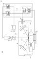
- FIG. 1 is a diagram showing the configuration of a visual inspection system according to the first embodiment.
- Visual inspection system 100 inspects defects on the surface of object 20 to be inspected.
- the object 20 is not particularly limited as long as it is an object that specularly reflects light on its surface. In specular reflection, the incident angle and reflection angle of the emitted light are equal. Diffuse light is light that is scattered and reflected in all directions.
- the object 20 is, for example, a plastic molded product whose surface is coated with epoxy resin.
- the surface of the object 20 (surface to be inspected) may be a flat surface or a curved surface.
- the types of defects that can be detected by the visual inspection system 100 include metal foreign objects, floating foreign objects, and voids.
- the metal foreign object is an object that is embedded in the surface of the object 20 and has a flat shape.
- the metal foreign matter includes, for example, copper, aluminum, and the like.
- the floating foreign matter is an object that is attached to the surface of the object 20 and has an uneven shape.
- Floating foreign matter includes, for example, dust, fiber foreign matter, and the like.
- Voids include, for example, depressions (chips) that occur on the surface due to poor molding.
- the visual inspection system 100 in FIG. 1 includes a camera unit that photographs the surface of an object 20 and generates an image, an illumination unit that irradiates the surface of the object 20 with light, and an image that is generated by photographing the surface of the object 20.
- a processing unit that inspects the presence or absence of defects on the surface of the object 20 based on the captured image; a beam splitter 7; a drive shaft 22; a motor 21 to which the drive shaft 22 is connected; a jig 23; It includes a power supply device 24, polarizing plates 9 and 11, and a computer 30 having a control section 35 and an inspection processing section 32.
- the inspection processing section 32 constitutes a processing unit that inspects the presence or absence of defects on the surface of the object 20 based on an image generated by capturing the surface of the object 20.
- the processing unit constituted by the inspection processing section 32 includes a first processing unit that provides image processing for inspecting the presence of voids or floating foreign matter on the surface, and a first processing unit that provides image processing for inspecting the presence of metallic foreign matter on the surface. and a second processing unit for providing.
- the motor 21 is a power device that converts electrical energy into mechanical energy, and in this embodiment, a DC pulse voltage is applied via a driver to output rotational motion.
- the drive shaft 22 is a rotation shaft that transmits the rotational driving force of the motor 21 to the object 20.
- the jig 23 supports the object 20 set on the jig 23 so that the outer peripheral surface, which will be described later, is placed within the imaging field of the camera unit.
- the power supply device 24 supplies power to the lighting unit.
- the object 20 has a cylindrical shape, and a defect inspection is performed on the outer peripheral surface (surface) exposed to the outside of the object 20.
- the object 20 has an axis passing through the center of a circle whose circumference is the circumference of the outer peripheral surface and extending in the longitudinal direction of the cylinder. By connecting this shaft to the drive shaft 22, the shaft rotates in conjunction with the rotation of the motor 21. As the axis rotates, the object 20 rotates concentrically with respect to the center of the circle.
- the cylindrical shape indicating the shape of the object 20 to be inspected is a concept that includes a substantially cylindrical shape, and the cylindrical shape also includes a hollow cylindrical shape.
- the shape of the object 20 is not limited to a cylindrical shape, and the surface of the object 20 to be inspected may be stationary without rotating during the visual inspection.
- the control unit 35 includes a camera control unit 31 that controls the camera unit, an illumination control unit 33 that controls the illumination unit to irradiate the illumination light onto at least the imaging field of the camera unit on the surface of the object 20, and a motor control unit.
- the inspection processing unit 32 performs inspection processing based on images captured and generated by the camera unit.
- the image generated and output from the camera unit constitutes, for example, image data in units of frames.
- the inspection processing performed by the inspection processing section 32 includes image processing on images from the camera unit.
- the motor control unit 34 outputs a number of pulse signals according to the step angle corresponding to the rotation amount (rotation angle and rotation speed) of the motor 21.
- the motor 21 is composed of a general stepping motor or a servo motor.
- the motor 21 has an ON/OFF cycle of a pulse signal as one pulse, and when one pulse signal is output, it rotates by one step angle, and the drive shaft 22 rotates in conjunction with the rotation.
- the motor control unit 34 outputs pulse signals for the number of pulses corresponding to the amount of rotation, it outputs a positioning completion signal. In this embodiment, when one pulse signal is output, a positioning completion signal is output.
- the lighting control section 33 is connected to the lighting unit and the power supply device 24, and controls turning on and off of the lighting unit, as well as controlling the intensity of the emitted light.
- the control unit 35 synchronizes the trigger signal output from the camera control unit 31, the lighting and extinguishing control signal output from the illumination control unit 33, and the pulse signal output from the motor control unit 34.
- a trigger signal is output for each step angle, and an image captured by the camera unit is generated.
- a trigger signal instructing the camera unit to take an image is output for each step angle, but the output interval of the trigger signal is not limited to each step.
- the camera unit includes a first camera 1 and a second camera 4.
- the first camera 1 and the second camera 4 each include a line sensor so as to be able to image a line-shaped inspection area 61, which will be described later.
- a line sensor is configured by arranging solid-state image sensors such as CCDs (Charge Coupled Devices) and photodiodes.
- the line sensor is not limited to one for monochrome imaging, but may be one for color imaging.
- the first camera 1 and the second camera 4 each receive light incident on the image sensor and output an electrical signal according to the amount of light received. An image is generated based on electrical signals output from the image sensor.
- the illumination unit includes a first illumination unit and a second illumination unit that constitute a light source for illuminating the surface of the object 20 to be imaged by the camera unit by irradiating the surface with illumination light.
- the first lighting unit includes a lighting device 12 and a lighting device 13
- the second lighting unit includes a lighting device 8 and a lighting device 10.
- Each lighting device includes a long line-shaped LED (Light Emitting Diode) so as to be able to irradiate an inspection area on a surface extending in a longitudinal direction parallel to the axis of the object 20 with diffused light. Including equipment.
- the computer 30 can be configured to include a processor circuit (processing circuit) having an arithmetic circuit, such as a personal computer, a microcomputer board, an ASIC (Application Specific Integrated Circuit), or an FPGA (Field Programmable Gate Array).
- the computer 30 may implement each part described above as a module provided by such a processor circuit executing a program, or a part or all of the functions provided by these modules may be implemented as a dedicated module. It may be implemented using other hardware circuits (eg, ASIC or FPGA).
- the illumination devices 8 and 10 adjust the brightness when imaging the surface of the object 20.
- the illumination devices 8 and 10 respectively irradiate the surface of the object 20 with irradiation lights L1 and L2 having only predetermined polarization angle components.
- Illumination devices 8 and 10 include polarizing plates 9 and 11, respectively. Polarizing plates 9 and 11 emit only light having only a predetermined polarization angle component among the light components irradiated from illumination devices 8 and 10, respectively.
- Irradiation lights L1 and L2 having only predetermined polarization angle components are irradiated onto the surface of the object 20.
- specularly reflected light LA1 is generated and enters the beam splitter 7.
- the beam splitter 7 is a cube-shaped beam splitter composed of two right-angled prisms.
- the beam splitter 7 is arranged in a direction in which the irradiated lights L1 and L2 are specularly reflected.
- the beam splitter 7 splits the incident light into two lights at a predetermined splitting ratio.
- the reflected light LA1 incident on the beam splitter 7 is split into reflected light LA2 and reflected light LA3.
- the reflected light LA2 is incident on the first camera 1.
- the reflected light LA3 is incident on the second camera 4.
- the first camera 1 and the second camera 4 simultaneously image the surface of the object 20.
- the first camera 1 images the surface of the object 20 from the direction of specular reflection of the irradiation light L1.
- the first camera 1 receives the reflected light LA2, captures an image of the surface of the object 20, and generates an image of the surface of the object 20.
- the first camera 1 includes a lens 2 and an ND (Neutral Density) filter 3 to which the lens 2 is attached.
- the ND filter 3 is also called a "neutral density filter" and reduces the amount of light by a certain amount over the entire predetermined wavelength band.
- the image generated by the light that has passed through the ND filter 3 will be referred to as an ND filter image.
- the light passing through the ND filter 3 includes light reflected from a flat metal foreign object embedded in the surface of the object 20 and light reflected from a floating foreign object.
- the lens 2 condenses the light that has passed through the ND filter 3 and forms an image at one point.
- the first camera 1 having the ND filter 3 images the surface of the object 20 and generates an ND filter image.
- the ND filter image is generated by light reflected from an embedded flat metal foreign object on the surface of the object 20 and light reflected from a floating foreign object.
- the second camera 4 images the surface of the object 20 from a direction perpendicular to the specular reflection direction of the irradiation light L1.
- the second camera 4 receives the reflected light LA3, captures an image of the surface of the object 20, and generates an image of the object 20.
- the second camera 4 includes a lens 5 and a PL (Polarized Light) filter 6 to which the lens 5 is attached.
- the PL filter 6 is also called a "polarizing filter” and is a lens filter that uses a polarizing film.
- a polarizing filter has a structure in which a polarizing film is sandwiched between two pieces of glass, and includes a rotating frame structure for rotating the direction of the polarizing film.
- the polarizing film of the PL filter 6 is mounted so that the direction of the polarizing film is perpendicular to the direction of polarization of light reflected from a foreign metal object embedded in the surface of the object 20.
- the lens 5 condenses the light that has passed through the PL filter 6 and forms an image at one point.
- the image generated by the light that has passed through the PL filter 6 will be referred to as a PL filter image.
- the polarization characteristics of incident light and reflected light are preserved as they are. It is known that reflected light from dust and fiber foreign matter having minute scattering particles becomes unpolarized light. Since the polarization direction of the light condensed by the lens 5 is perpendicular to the light reflected from the metal foreign object, if there is a flat metal foreign object embedded in the surface of the object 20, that part will appear dark. On the other hand, if there is a floating foreign substance having irregularities on the surface of the object 20, that part will appear bright.
- the light passing through the ND filter 3 includes light reflected from buried flat metal foreign matter, floating foreign matter, and voids present on the surface of the object 20.
- the light transmitted through the PL filter 6 does not include the light reflected from the metallic foreign matter blocked by the PL filter 6, but includes only the light reflected from the floating foreign matter or voids.
- the metallic foreign matter, floating foreign matter, and voids are brightly emphasized in the ND filter image, and in the PL filter image, Only floating foreign objects and voids are highlighted brightly. Therefore, the presence or absence of a metal foreign object can be identified based on a difference image showing the difference between the ND filter image and the PL filter image, which is obtained by comparing the two images. In this embodiment, since the ND filter image and the PL filter image can be generated simultaneously, the time required for the visual inspection can be reduced compared to the case where the images are generated separately.
- the illumination devices 12 and 13 irradiate the surface of the object 20 with imaging light for identifying whether a defect is a void.
- the illumination devices 12 and 13 emit light having different wavelengths for void identification processing to be described later.
- the illumination devices 12 and 13 irradiate the surface of the object 20 with irradiation lights L3 and L4.
- irradiation lights L3 and L4 When the irradiation lights L3 and L4 are incident on the surface of the object 20, a specular reflected light LA1 is generated from the surface, and the reflected light LA1 is incident on the beam splitter 7.
- the reflected light LA1 incident on the beam splitter 7 is split into reflected light LA2 and reflected light LA3, which are focused on the lenses 2 and 5, respectively.
- the reflected light LA2 is incident on the first camera 1 via the lens 2, and the first camera 1 generates an image based on the reflected light LA2.
- the reflected light LA3 is incident on the second camera 4 via the lens 5, and the second camera generates an image based on the reflected light LA2.
- the illumination devices 12 and 13 respectively irradiate the surface of the object 20 with irradiation lights L3 and L4 from horizontal and different directions.
- This horizontal also includes the concept of approximately horizontal.
- the irradiation lights L3 and L4 that are irradiated horizontally to the surface in this way are applied to the portion of the surface of the object 20 where the void is formed. It is not reflected in other parts where voids are not formed. Therefore, in the state where the irradiation lights L3 and L4 are irradiated, the reflected light LA1 includes the reflected light in the portion where the void is formed, and the reflected light in other portions is attenuated.
- the images generated by the first camera 1 and the second camera 4 have excellent contrast between the portion of the surface of the object 20 where the void is formed and the other portions. Even if the images captured and generated by the first camera 1 and the second camera 4 in a state where the illumination lights are irradiated from the illumination devices 12 and 13 are an ND filter image and a PL image, these images also have The excellent contrast described above can be obtained. Note that the ND filter 3 attenuates bands other than the wavelengths of the irradiated lights L3 and L4.
- the surface in the configuration for detecting metal foreign objects, is imaged with the illumination light from the illumination device 8 equipped with the polarizing plate 9 and the illumination device 10 equipped with the polarizing plate 11, whereas voids are detected.
- the surface is imaged with the illumination light from the illumination devices 12 and 13 to which no polarizing plate is attached. In this way, identification of the presence or absence of metallic foreign objects and identification of the presence or absence of voids are performed based on images generated by imaging under illumination conditions (irradiation angle and polarization) adapted to each.
- the illumination devices 8 and 10 equipped with the polarizing plates 9 and 11 emit a first irradiation light having a first wavelength and a second irradiation light having a second wavelength with respect to the surface of the object 20 horizontally from different directions. It is also possible to irradiate the irradiation light of step 2 and identify metal foreign objects and voids using the captured image.
- FIG. 2 is a diagram showing an example of a timing chart of control according to the first embodiment.
- the horizontal axis shows the passage of time and also shows the control cycle CY.
- a control signal for controlling lighting (ON) and extinguishing (OFF) of the lighting devices 8, 10, 12, and 13 and a control signal for controlling the lighting devices 8, 10, 12, and 13, A trigger signal that instructs imaging, a motor pulse signal that rotates the motor 21 by one step angle, and a positioning completion signal are shown.
- the object 20 is set on the jig 23 in advance, and the lighting devices 8, 10, 12, and 13 are in the off state as an initial state.
- the first control cycle CY is started at time T0.
- no motor pulse signal is output, and a lighting control signal is output to the lighting devices 8 and 10 at timing (a).
- a trigger signal is then output to the first camera 1 and the second camera 4.
- the first camera 1 and the second camera 4 take an image of the surface in response to the trigger signal and output the image. .
- a control signal for turning on is output to the lighting devices 12 and 13, and a control signal for turning off the light is output to the lighting devices 8 and 10.
- the lighting devices 8 and 10 are turned off and the lighting devices 12 and 13 are turned on
- a trigger signal is output to the first camera 1 and the second camera 4.
- the first camera 1 and the second camera 4 take an image of the surface in response to the trigger signal and output the image. do.
- a control signal to turn off the lights is output to the lighting devices 12 and 13, and the lighting devices 12 and 13 turn off in response to the control signal.
- a pulse signal is output at timing (e) at the start of the control cycle, and the motor 21 rotates in response to the pulse signal and is linked to the rotation.
- the inspection area located in the imaging field of view on the surface of the object 20 is then switched.
- a positioning completion signal is output at timing (e) when the rotation of the motor 21 ends.
- a lighting control signal is output to the lighting devices 8 and 10 at a subsequent timing (f).
- the illumination devices 8 and 10 turn on in response to the control signal and emit light, and then a trigger signal is output to the first camera 1 and the second camera 4 at timing (g).
- the first camera 1 and the second camera 4 capture an image of the surface in response to the trigger signal and output an image.
- a control signal for turning on is output to the lighting devices 12 and 13, and a control signal for turning off the light is output to the lighting devices 8 and 10.
- the lighting devices 8 and 10 are turned off and the lighting devices 12 and 13 are turned on, and at subsequent timing (i), a trigger signal is output to the first camera 1 and the second camera 4. .
- the first camera 1 and the second camera 4 take an image of the surface in response to the trigger signal and output the image. do.
- a control signal to turn off the lights is output to the lighting devices 12 and 13, and the lighting devices 12 and 13 turn off in response to the control signals.
- the trigger signal from the camera control section 31, the control signal for turning on and off from the lighting control section 33, and the pulse signal from the motor control section 34 are output in synchronization with each other.
- the inspection area is imaged at every step angle and an image is output.
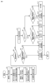
- FIG. 3 is a flowchart showing the procedure of inspection processing according to the first embodiment.
- the flowchart of FIG. 3 shows, for example, processing for images for each step angle acquired in each control period CY of FIG. 2.
- FIG. 4 is a flowchart of metal foreign object identification processing according to the first embodiment.
- FIG. 5 is a diagram illustrating the difference processing between the ND filter image and the PL filter image according to the first embodiment.
- FIG. 6 is a flowchart of void identification processing according to the first embodiment.
- FIG. 7 is a diagram illustrating reflection of irradiation light from floating foreign objects according to the first embodiment.
- FIG. 8 is a diagram illustrating reflection of irradiation light from a void according to the first embodiment.
- step A1 of FIG. 3 the lighting control unit 33 turns on the lighting devices 8 and 10.
- step A2 the camera control section 31 outputs a trigger signal to the first camera 1 and the second camera 4.
- the surface of the object 20 is simultaneously captured by the first camera 1 and the second camera 4, and an ND filter image and a PL filter image are output.
- step A3 the lighting control unit 33 turns off the lighting devices 8 and 10, and turns on the lighting devices 12 and 13.
- step A4 the camera control unit 31 outputs a trigger signal to the first camera 1. Thereby, the surface of the object 20 is imaged by the first camera 1, and an ND filter image is output.
- a trigger signal is output to at least the first camera 1 or the second camera 4, and the surface of the object irradiated with the irradiation light from the first illumination unit is imaged.
- images that can be used for void identification processing are not limited to ND filter images, but may also be PL filter images that are captured and generated by the second camera 4, and may also include ND filter images and PL filter images. Both may be used as images for void identification processing.
- the ND filter image Since the PL filter image according to this embodiment has a characteristic that the brightness of the entire image is lower than that of the ND filter image, the ND filter image is acquired in step A4. Even if the ND filter image includes a partial image of the metal foreign object, the position information indicating the position of the partial image of the metal foreign object in the ND filter image should be obtained from the difference image indicating the difference between the ND filter image and the PL filter image. Can be done. Therefore, the partial image of the metal foreign object can be detected and excluded from the ND filter image using the position information.
- step A5 the second processing unit of the inspection processing section 32 performs the foreign metal identification process shown in FIG. 3.
- step A5-1 of FIG. 3 the inspection processing unit 32 performs differential processing using the ND filter image output from the first camera 1 and the PL filter image output from the second camera 4 in step A2. Execute and generate a difference image.
- ND filter image 300 includes partial images of metal foreign matter W1 and floating foreign matter W2, and PL filter image 301 includes a partial image of floating foreign matter W2.
- the pixel values of the PL filter image are subtracted from the pixel values of the ND filter image, and the result indicates the pixel value of the difference image 302.
- the difference image 302 of FIG. 5 only a partial image of the metal foreign object W1 remains.
- step A5-2 the inspection processing unit 32 generates a binarized image by binarizing the pixel values of the difference image using a predetermined binarization threshold.
- the inspection processing unit 32 sets the pixel value to "1" when the value of the pixel of the difference image is equal to or higher than the binarization threshold, and sets the value of the pixel to "1" when the value of the pixel of the difference image is less than the binarization threshold. sets the value of that pixel to "0".
- step A5-3 the inspection processing unit 32 performs labeling processing on the binarized image.
- labeling processing is a process of classifying multiple regions in a binarized image as a group by adding the same label "1" to connected pixels in the binarized image, and is a process known in the field of image processing. technology, so detailed explanation will not be repeated.
- step A6 the second processing unit of the inspection processing section 32 determines whether the surface of the object 20 contains a metal foreign substance based on the partial image of the metal foreign substance included in the difference image described above. Determine whether More specifically, the inspection processing unit 32 determines, for each region, one or more regions formed by a plurality of pixels labeled with “1” in the partial image of the metal foreign object in the difference image. Measure the area of .
- the inspection processing unit 32 determines that there is a region whose area is equal to or greater than the threshold value (YES at step A6), the inspection processing unit 32 moves to the processing from step A9 onwards for evaluating metal foreign objects, and determines that there is no region whose area is equal to or greater than the threshold value. If it is determined that this is the case (NO in step A6), the process proceeds to step A7, which identifies voids.
- step A7 the first processing unit of the inspection processing section 32 performs a process of identifying voids using the ND filter image acquired in step A4.
- the inspection processing unit 32 extracts color information specific to voids or floating foreign objects from the ND filter image.
- the color of an image indicates the gradation value of each pixel that makes up the image.
- the illumination devices 12 and 13 each emit light of different wavelengths (different colors), so depending on the relationship between the color of the ND filter image and the direction in which the light is irradiated, foreign matter may be void or floating. Foreign objects are identified. An identification method based on such a relationship will be explained with reference to FIGS. 7 and 8. 7 and 8, the first camera 1 and illumination devices 12 and 13 of the visual inspection system 100 of FIG. 1 are shown, and other components are omitted for simplicity of explanation. ing.
- FIG. 7 shows a case where the floating foreign matter P6 on the surface of the object 20 is irradiated with irradiation lights of different wavelengths from different directions horizontally to the surface.
- FIG. 8 shows a case in which a void P7 formed on the surface of the object 20 is irradiated with irradiation lights of different wavelengths from different directions parallel to the surface.
- irradiation lights L3 and L4 having different wavelengths are irradiated from the left and right sides of the first camera 1, respectively.
- the irradiation light L3 is reflected on the left surface of the floating foreign object P6, the reflected light LA(3) on the left surface is incident on the first camera 1, and the irradiation light L4 is reflected on the right surface of the floating foreign object P6, The reflected light LA(4) on the right surface enters the first camera 1.
- the irradiated light L3 is reflected at the right surface of the void P7, and its reflected light LA(3) is incident on the camera 1
- the irradiated light L4 is reflected at the left surface of the void P7, and its reflected light LA(3) (4) is incident on camera 1.
- the irradiation lights LA(3) and LA(4) are directed to the left and right sides of the array surface of the image sensor of the first camera 1, respectively. enter the position.
- the irradiation lights LA(3) and LA(4) are incident on the right and left positions on the array surface of the image sensor, respectively. In this way, the positions at which the reflected light is incident on the array surface of the image sensor are switched between the left and right sides.
- the wavelength (color) of the reflected light LA(3) there is a difference in the wavelength (color) of the reflected light LA(3) between the ND filter image generated by capturing the floating foreign object P6 in FIG. 7 and the ND filter image generated by capturing the void P7 in FIG.
- the arrangement of the partial image and the wavelength (color) of the reflected light LA(4) are different.
- the model image showing the color arrangement pattern of the floating foreign matter P6 is called a pattern C1
- the model image showing the color arrangement pattern of the void P7 is called a pattern C2.
- step A7-1 the inspection processing unit 32 compares the ND filter image with the pattern C2, and determines whether the partial image of the void P7 is included in the ND filter image based on the comparison result. More specifically, the inspection processing unit 32 scans the ND filter image with the pattern C2, and identifies whether or not a partial image indicating the color arrangement of the void P7 is included based on the scan result. The inspection processing unit 32 also compares the ND filter image with the pattern C1, and determines whether the ND filter image includes a partial image of the floating foreign object P6 based on the comparison result. More specifically, the inspection processing unit 32 scans the ND filter image with the pattern C1, and identifies whether or not a partial image indicating the color arrangement of the floating foreign matter P6 is included based on the scan result. These identification results are output as color information.
- step A7-2 the inspection processing unit 32 converts the ND filter image into a grayscale image, and generates a binarized image from the grayscale image using a predetermined binarization threshold.
- step A7-3 the inspection processing unit 32 performs labeling processing on the binarized image.
- labeling processing classifies a plurality of regions as a group by adding the same label "1" to connected pixels in a binarized image, similar to the method described above.
- step A7-4 the inspection processing unit 32 compares the labeling processing information obtained from the ND filter image in steps A7-2 and A7-3 with a predetermined pattern C3 indicating the shape characteristics of the void. , Based on the matching results, it is determined whether the ND filter image includes a partial image representing a shape characteristic of the void.
- Pattern C3 includes a model image showing the characteristics of the shape of such a void.
- step A7 it is determined from the color information and shape characteristics whether or not the ND filter image includes a void partial image.
- void identification uses the logical sum of the judgment result based on color information and the judgment result based on shape characteristics, but is not limited to the logical sum, and other judgment conditions such as logical product may also be used. good.
- step A8 the inspection processing unit 32 determines whether the ND filter image includes a void partial image based on the processing result of step A7. If it is determined that a partial image of a void is included (YES in step A8), the inspection processing unit 32 performs the void determination process from step A10 onwards, and determines that a partial image of a void is not included. If so (NO in step A8), the inspection processing unit 32 executes the floating foreign object determination process from step A11 onwards.
- the inspection processing unit 32 determines whether the area of the foreign object is greater than or equal to a predetermined threshold value. More specifically, the inspection processing unit 32 measures the area of each region formed by a plurality of pixels to which the same label is added in the ND filter image. Then, it is determined whether the measurement result is greater than or equal to a predetermined threshold value.
- area is used as a feature quantity for determination, but depending on the inspection standard, different feature quantities such as main axis length, minor axis length, circumference length, etc. may be used for determination.
- FIG. 9 is a diagram showing feature amounts used in the inspection according to the first embodiment. It is assumed that a partial image of an identified defect such as a metal foreign object, a floating foreign object, or a void has the shape of the shaded area in FIG. 9 .
- the inspection processing unit 32 sets a rectangle circumscribing such a partial image. In FIG. 9, a circumscribed rectangle having, for example, 4 ⁇ 4 pixels is set.
- the feature values of a partial image of such a defect include the area S of the partial image based on the size of the circumscribed rectangle, the principal axis length L indicating the longitudinal length of the partial image based on the size of the circumscribed rectangle, and the size of the circumscribed rectangle.
- the sub-axis length W indicates the length of the partial image in the lateral direction based on the size of the circumscribed rectangle
- the peripheral length CL indicates the circumferential length of the partial image based on the size of the circumscribed rectangle.
- step A12 determines in step A9 of FIG. (step A12), and if it is determined that the area value is not equal to or greater than the threshold value (NO in step A9), an OK determination indicating that no metal foreign matter has been detected on the surface of the object 20 is output ( Step A13). Further, when the inspection processing unit 32 determines that the area value of the partial image is equal to or greater than the threshold value in step A10 of FIG. 3 (YES in step A10), this indicates that a void has been detected on the surface of the object 20.
- Step A14 It outputs an NG determination (step A14), and if it determines that the area value is not equal to or greater than the threshold value (NO in step A10), it outputs an OK determination indicating that no voids have been detected on the surface of the object 20 ( Step A15). Further, if the inspection processing unit 32 determines in step A11 of FIG. If it is determined that the area value is not equal to or greater than the threshold value (NO in step A11), no defects (metallic foreign matter, voids, floating foreign matter) are detected on the surface of the object 20. A determination of OK is output indicating that this is the case (step A17).
- defects on the surface of the object 20 are detected due to differences in reflection characteristics of irradiation light based on differences between metals and non-metals, and differences in shapes of floating foreign objects and voids.
- differences in the reflection characteristics of irradiated light it is possible to identify the presence or absence and type of defects without complicating the camera unit.
- the visual inspection system 100 includes both a configuration for identifying the presence or absence of voids or floating foreign objects and a configuration for identifying metal foreign objects, but may include only one of the configurations.
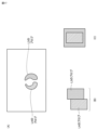
- FIG. 10 is a diagram showing an example of outputting test results according to the first embodiment.
- test results are displayed in windows 70, 71, 72, 73, and 74.
- the window 70 displays an object 60, which is an image schematically showing the outer peripheral surface of the cylindrical object 20, and an object showing a line-shaped inspection area 61 in the object 60.
- the window 72 displays information 57 indicating the feature amount used for identification and its threshold value for each defect to be identified (metal foreign matter, floating foreign matter, void).
- an object 50 indicating the processing result of the visual inspection is displayed.
- the object 50 shows the entire outer peripheral surface of the object 20 by combining a plurality of inspection areas 61. Defects detected during inspection are shown overlaid on object 50 as object 51 .
- the window 74 shows the type of defect and determination value for the object 51 shown in the window 71.
- the defect identifier 56 for each object 51 shown in the window 71, the defect identifier 56, the defect type 55, the defect determination 54, the feature amount 53 of the defect, and the defect position 52 of the object 51 are displayed. shown.
- the determination 54 indicates the determination value in any of steps A12 to A17 in FIG. 3 for the partial image of the defect.
- the position 52 means that the detected position on the surface of the defect is the coordinate position (XY coordinate values).
- the XY coordinate position of the partial image in the image of the inspection area 61 is also detected.
- the X-coordinate position of the inspection area 61 is calculated based on the number of pulse signals output from the start of the visual inspection of the object 20. be done.
- the inspection processing unit 32 determines the coordinate position of the defect object 51 based on a predetermined calculation based on the XY coordinate position of the defect in the inspection area 61 and the X coordinate position on the outer peripheral surface (surface) of the inspection area 61.
- the position 52 is calculated.
- the visual inspection system 100 includes an object window 71 in which an object 51 indicating a detected defect is overlaid on an object 50 indicating the surface of the object 20, so that the user can monitor the inspection results. and an object indicating the type 55 or position 52 of the object are displayed on the display 1003 in association with each other.
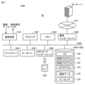
- FIG. 11 is a diagram illustrating an example of the configuration of a visual inspection system according to the second embodiment.
- visual inspection system 1000 includes a computer 30 and a server 40 that communicates with computer 30.
- the computer 30 includes a processor 1001 , a memory 1002 , a display 1003 , a keyboard 1005 , a memory card interface 1004 to which a memory card 1007 is removably attached, and an HDD (Hard Disk Driver) 1006 connected by a bus 1008 .
- HDD Hard Disk Driver
- the processor 1001 implements the visual inspection process shown in FIG. 3 by expanding the program stored in the HDD 1006 into the memory 1002 and executing it.
- the HDD 1006 stores system programs including an OS (Operating System) 120, application programs, and data.
- the data includes test data 124 indicating test results and pattern information 125 having patterns C1, C2, and C3.
- the application program includes a control program 121 that realizes the control unit 35 when executed, an inspection program 122 that realizes the inspection processing unit 32 when executed, and a UI (User Interface) program 123.
- the UI program 123 When executed, the UI program 123 outputs information regarding visual inspection to the user and provides a UI tool that accepts user operations on the computer 30.
- the information in FIG. 10 is displayed on the display 1003 by the UI tool.
- the computer 30 includes both the control unit 35 and the test processing unit 32, but the test processing unit 32 may be implemented in a device external to the computer 30, such as the server 40 in FIG. 11.
- the server 40 includes an on-premises server configured with a general-purpose computer or a server on a cloud.
- the computer 30 transfers the image received from the camera unit to the server 40 via the communication interface 1009 and the network 310.
- the server 40 executes the visual inspection process shown in FIG. 3 on the image received from the computer 30, and transfers the execution result to the computer 30 as, for example, Web page information.
- the web browser of the computer 30 causes the display 1003 to display, for example, the screen shown in FIG. 10 based on the web page transferred from the server 40. Further, the screen shown in FIG. 10 showing the results of the inspection process may be displayed on a display (not shown) included in the server 40.
- FIG. 12 is a flowchart of a process for identifying metal foreign objects according to the first embodiment.
- the inspection processing unit 32 performs the foreign metal identification process shown in the flowchart of FIG.
- the inspection processing section 32 may further include a processing unit that performs identification based on the color components described above.
- this processing unit generates an ND filter image and a PL filter image generated by capturing an image of the surface of the object 20 irradiated with light of a predetermined wavelength from the second illumination unit.
- This predetermined wavelength includes a wavelength of light corresponding to the color component of the surface of the object 20.
- step A12-0 of FIG. 12 the inspection processing unit 32 acquires the ND filter image output from the first camera 1 and the PL filter image output from the second camera 4.
- the inspection processing unit 32 extracts only a predetermined color component of RGB, that is, the red (R) component, from the PL filter image. For example, the inspection processing unit 32 scans the PL filter image using pixel values indicating predetermined color components, and based on the scan results, generates a partial image composed of pixels of the red (R) component from the PL filter image. Extract only.
- a predetermined color component of RGB that is, the red (R) component
- step A12-9 the inspection processing unit 32 performs filter processing on the extracted partial image of the red component in order to emphasize this partial image, and in step A12-10, converts the filtered partial image into a binary image.
- the inspection processing unit 32 scans a partial image using a predetermined pixel value as a threshold, and extracts a portion exceeding the threshold from the binarized partial image.
- This threshold value corresponds to a pixel value for extracting a partial image of a metal foreign object embedded in the surface of the object 20.
- step A12-11 the inspection processing unit 32 performs labeling processing on the binarized partial image.
- step A12-12 the inspection processing unit 32 performs size determination for each of the different regions to which the same label is attached in the partial image through the labeling process. Each region with the same label corresponds to a blob corresponding to a metal. A blob indicates a collection of pixels having the same density (pixel value).
- the inspection processing unit 32 detects the area of each blob and the XY coordinate position of this blob in the partial image.
- step A12-13 the inspection processing unit 32 extracts the XY coordinate positions of one or more blobs whose size has been determined. Each of the extracted XY coordinate positions of one or more blobs indicates a candidate position of the metal foreign object in the partial image.
- the predetermined color component is not limited to red.
- the predetermined color components may be set according to the surface color of the object 20 to be inspected. In the process shown in FIG. 12, the surface of the object 20 is, for example, reddish brown. Therefore, the predetermined color component indicates a red (R) component, which is a color component that is easy to extract.
- the inspection processing unit 32 facilitates binarization by extracting a red component close to the color component of the surface of the object 20. More specifically, since the light reflected from the surface of the metal foreign object is attenuated by passing through the PL filter, the amount of light reflected from the surface is small and becomes dark. Focusing on this point, when the inspection processing unit 32 performs binarization on a partial image corresponding to a red component close to the surface color from the PL filter image, in the partial image after binarization, bright areas start to darken. The region can be easily extracted as a candidate position (XY coordinate position) of the embedded metal foreign object.
- the inspection processing unit 32 performs the above-described filter processing and binary processing on the ND filter image acquired in step A12-1 in step A12-1, step A12-3, step A12-4, and step A12-5. , labeling processing, size determination, and extraction of multiple candidate positions (XY coordinate positions). As a result of such processing, the XY coordinate position of each blob in the ND filter image is extracted for both brightly shining metallic blobs and non-metallic blobs.
- the inspection processing unit 32 detects the matching rate for each of the one or more candidate positions extracted in the PL filter image. More specifically, for each of one or more candidate positions extracted in the PL filter image, the inspection processing unit 32 converts the XY coordinate position of the candidate position into the XY coordinate position of each blob extracted in the ND filter image. Based on the comparison result, the coincidence rate of the XY coordinate values is calculated. For example, for each candidate position, the XY coordinate position of the candidate position is compared with the XY coordinate position of each blob extracted in the ND filter image. The result of the comparison indicates, for example, the XY coordinate position of the blob that is closest to the XY coordinate position of the candidate position.
- the match rate indicates, for example, a value based on the magnitude of the deviation between the XY coordinate position of the candidate position and the XY coordinate position of the blob indicating the closest position.
- the magnitude of the deviation is, for example, the distance between the XY coordinate position of the candidate position and the XY coordinate position of the blob indicating the closest position. The shorter the distance, the higher the matching rate.
- step A12-7 the inspection processing unit 32 compares the matching rate of the candidate position with a threshold value for each of the one or more candidate positions extracted in the PL filter image, and the comparison result is (matching rate>threshold value). , it is determined that the candidate position is a metal foreign object embedded in the surface.
- the inspection processing section 32 outputs the determination result. This output includes displaying the determination result, storing it in a storage medium, transferring it, etc. This determination result may include the determined XY coordinate position of the metal foreign object.
- the inspection processing unit 32 can identify defects on the surface of the object 20 (metallic foreign matter embedded in the surface) based on the color components of the PL filter image, and can identify the XY coordinate position of the metallic foreign matter. can be identified.
- the inspection processing unit 32 may identify whether a defect on the surface of the object 20 is a void based on the characteristics of an image formed by a difference in the wavelength of light irradiated to the defect.
- FIG. 13 is a flowchart of a process for identifying voids according to the first embodiment.
- the inspection processing unit 32 executes the processing shown in the flowchart of FIG. 13.
- FIG. 14 is a diagram showing an example of an image of defects and blobs.
- FIGS. 15, 16, and 17 are diagrams each showing an example of a blob image. For purposes of explanation, the images in FIGS. 15A, 16A, and 17A have in common the images in FIG. 14A.
- the irradiation light L3 is reflected on the right side of the depression, which is a defect, and the reflected light LA(3) is incident on the camera 1, and the irradiation light L4 is reflected on the left side of the void P7, and the reflected light LA(3) is reflected on the left side of the void P7.
- (4) is incident on camera 1. Since the irradiation light L3 and the irradiation light L4 have different wavelengths, the reflected light LA(3) and the reflected light LA(4) incident on the camera 1 also have different wavelengths. Therefore, in the configuration of FIG. 8, when the depression shown in (A) of FIG. 14 is imaged by the camera 1, in the captured image, the 2 Two images are detected.
- the inspection processing unit 32 Based on the positional relationship between the images of the “L3 blob” and “L4 blob” in the captured image, the inspection processing unit 32 detects the “L3 blob” and “L4 blob” when the positional relationship satisfies a predetermined condition. Identify (detect) voids consisting of "blobs".
- the inspection processing unit 32 acquires an image captured by the camera 1.
- the acquired image is a PL filter image or an ND filter image.
- the inspection processing unit 32 acquires the XY coordinate positions of the "L3 blob" image and "L4 blob” image in FIG. 14(B) in the image by scanning the image, and uses the acquired XY coordinates. Compare positions.
- the inspection processing unit 32 compares the Y coordinates of the two blobs in (A) of FIG. Specifically, the Y coordinate value of the center position of the "L4 blob" is compared with the upper and lower limits of the Y coordinate of the "L3 blob". Based on the comparison results, the inspection processing unit 32 determines that the condition that the Y coordinate value of the center position is between the upper and lower limits as shown in FIG. If the depression in (A) is determined to be a void candidate, and it is determined that the condition that the Y coordinate value of the center position is between the upper and lower limit values is not satisfied as shown in (C) in FIG. It is determined that the depression in (A) is not a void.
- step A13-2 regarding the two blobs in (A) of FIG. Search (scan) the image in the direction of the blob. More specifically, the inspection processing unit 32 searches in the X direction from the right end of the "L4 blob" to a distance corresponding to the principal axis length of the blob, and determines whether the condition for finding the "L3 blob" is met. judge whether As a result of the search, if the “L3 blob” is detected as shown in FIG. 16 (B) and it is determined that the conditions are satisfied, the inspection processing unit 32 determines that the depression shown in FIG. 14 (A) is a void candidate. However, when it is determined that the "L3 blob" cannot be detected and the conditions are not satisfied as shown in FIG. 16(C), it is determined that the depression shown in FIG. 14(A) is not a void.
- step A13-3 when the inspection processing unit 32 determines that the depression is a void candidate, in step A13-3, for the two blobs in (A) of FIG. Compare the X coordinates of Specifically, the left end X coordinate value of "L4 blob" is compared with the left end X coordinate value of "L3 blob", and based on the comparison result, the left end of "L4 blob” is "L3 blob". It is determined whether the condition of being to the left of the left edge of "Blob" is satisfied. When the inspection processing unit 32 determines that the condition that the left end of the "L4 blob" is on the left side of the "L3 blob" is satisfied as shown in FIG.
- the inspection processing unit 32 determines that the depression is a void. However, if it is determined that the left end of the "L4 blob" is not to the left of the left end of the "L3 blob" and the condition is not satisfied, as shown in FIG. 17(C), it is determined that the depression is not a void.
- the inspection processing unit 32 outputs the determination result of step A13-3. This output includes displaying the determination result, storing it in a storage medium, transferring it, and so on.
- FIG. 18 is a diagram illustrating an example of the configuration of a visual inspection system according to Embodiment 3.
- the visual inspection system 1000A of the third embodiment differs from the visual inspection system 1000 of FIG. 11 of the first embodiment in that the visual inspection system 1000A of the third embodiment includes a computer 30A instead of the computer 30. It is.
- the configuration of the visual inspection system 1000A other than the computer 30A is the same as the configuration shown in FIG. 11, so the description will not be repeated.
- the computer 30A is equipped with a device that collects learning data.
- the computer 30A collects learning data, performs learning to generate a learned model, and performs inference and testing using the learned model.
- the computer 30A includes, in the HDD 1006A, a learning program 131, an inference program 132, and an inference-based inspection program 133 in addition to the programs and data stored in the HDD 1006 in FIG.
- the learning program 131 configures the learning device 190 when executed.
- the learning device 190 acquires learning data using the inspection data 124 acquired using the rule base. More specifically, when the inspection process shown in FIG. The inspection result is obtained based on the image, the ND filter image, and the PL filter image and the ND filter image obtained under illumination light from the illumination device 12 and the illumination device 13). The inspection results are classified into one of four types: metal foreign matter, floating matter, void, and OK determination. By performing the inspection process in FIG. 3, inspection results according to the rule base are acquired, and inspection data 124 including the acquired inspection results is stored in the HDD 1006A.
- the inspection data 124 includes the four types of images described above and the inspection results corresponding to each image.
- the inspection result includes at least the defect type 55 (the type is any one of metal foreign matter, floating matter, void, and OK) determined for the corresponding image.
- Type 55 indicates a determination value in any one of steps A12 to A17 in FIG.
- the inspection data 124 includes a set of a PL filter image acquired under illumination light from the illumination device 8 and the illumination device 10 and an inspection result corresponding to the PL filter image, and a set of the inspection result corresponding to the PL filter image, the illumination device 8 and the illumination A set of an ND filter image acquired under illumination light from the device 10 and an inspection result corresponding to the ND filter image, and a PL filter image acquired under illumination light from the illumination device 12 and the illumination device 13. and a set of inspection results corresponding to the PL filter image, and a set of an ND filter image acquired under illumination light from the illumination device 12 and the illumination device 13 and an inspection result corresponding to the ND filter image. Since FIG.
- the determination values in steps A12 to A17 represent rule-based determination values (inspection results).
- the test processing unit 32 or the learning device 190 simultaneously performs an annotation operation in which a label indicating the type of judgment 55 included in the set is added to each set of the test data 124. Implemented.
- FIG. 19 is a diagram showing the configuration of a learning device 190 according to the third embodiment.
- the learning device 190 performs a learning process using learning data to obtain a learned model 134.
- the learning device 190 includes a data acquisition unit 193 that acquires an image 191 representing image data and a label 192 indicating a judgment value “OK” corresponding to this image 191, and a model generation unit 194 that generates a trained model 134. Be prepared.
- the image 191 is composed of four types of images (a PL filter image and an ND filter image obtained under illumination light from illumination device 8 and illumination device 10, and an image obtained under illumination light from illumination device 12 and illumination device 13).
- the data acquisition unit 193 acquires the image 191 by searching the inspection data 124 of the HDD 1006A for a set labeled "OK".
- the data acquisition unit 193 acquires the image data of the image 191 indicating the determination value "OK” as learning data.
- the image 191 indicating the determination value "OK” is not limited to one obtained by searching the inspection data 124 of the HDD 1006A.
- the data acquisition unit 193 uses a PL filter image obtained by imaging the surface of the object 20 (i.e., a non-defective product) free of defects (metallic foreign objects, floating objects, and voids) using a camera.
- an ND filter image may be acquired as the image 191.
- the model generation unit 194 generates a learned model 134 that reconstructs an image of a non-defective item from the image 191 of a non-defective item, which is the learning data acquired by the data acquisition unit 193 (non-defective learning). More specifically, when the learning data image 191 indicates a non-defective ND filter image, the model generation unit 194 generates a learned model 134 that reconstructs a non-defective ND filter image from the non-defective ND filter image. (good product learning), and when the image 191 of the learning data indicates a good product PL filter image, a trained model 134 that reconstructs a good product PL filter image from the good product PL filter image is generated (good product learning).
- a known algorithm such as supervised learning, unsupervised learning, or reinforcement learning can be used.
- supervised learning unsupervised learning
- reinforcement learning can be used.
- Embodiment 3 a case where a neural network learning algorithm is applied will be described as an example.
- the model generation unit 194 performs good quality learning by so-called unsupervised learning, for example, according to a neural network model.
- unsupervised learning only images 191 of non-defective products are given to the learning device 190 without linking data sets of results (labels) to inputs.
- the model generation unit 194 learns the feature amounts of the image 191 of a non-defective product and generates a learned model 134 that reconstructs an image of a non-defective product from the image 191 of a non-defective product.
- supervised learning refers to providing a set of input and result (label) data to the learning device 190, which learns the feature values in those learning data, and then learns the feature values in the training data and selects the features among the input results (labels).
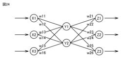
- FIG. 24 is a diagram showing an example of the configuration of a neural network.
- a neural network is composed of an input layer consisting of a plurality of neurons, an intermediate layer (hidden layer) consisting of a plurality of neurons, and an output layer consisting of a plurality of neurons.
- the intermediate layer includes one layer, or two or more layers.
- the input layer (X1 to Each input value after multiplication is accepted in the layer (Y1 to Y2), and each accepted input value (multiplication result) is further multiplied by weight W2 (w21 to w26) and output from the output layer (Z1 to Z3). Ru. This output result changes depending on the values of weights W1 and W2.
- the neural network learns the feature amount of the image 191 of a non-defective product by so-called unsupervised learning according to the image 191 of the non-defective product acquired by the data acquisition unit 193. That is, the neural network inputs the image 191 of a non-defective product into the input layer and sets the weights W1 and W2 so that the reconstructed image data output from the output layer approaches the image 191 of the non-defective product input into the input layer. Implement learning by adjusting.
- the model generation unit 194 generates and outputs the trained model 134 by performing the learning described above.
- the model generation unit 194 stores the learned model 134 in the HDD 1006A.
- the model generation unit 194 may perform learning according to a deep learning algorithm, such as a convolution processing (Convolution Neural Network) algorithm, which learns so as to be able to extract the feature amount itself.
- a convolution processing Convolution Neural Network
- the model generation unit 194 can use an autoencoder (self-encoder) as a learning algorithm.
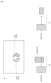
- FIG. 20 is a diagram illustrating unsupervised learning using an autoencoder.
- the model generation unit 194 provides the autoencoder with only input data (image data of the image 191) that does not include a judgment value (label) as learning data.
- the autoencoder extracts feature quantities from input data, reconstructs (reproduces/builds) and outputs an image having feature quantities close to the extracted feature quantities.
- the autoencoder is an algorithm that reconstructs and outputs an image close to (almost the same as) the input image. Therefore, the reconstructed image is close to that of image 191.
- the autoencoder includes a first layer corresponding to the encoder 234 and a second layer corresponding to the decoder 245, and the encoder 234 and the decoder 245 constitute an integrated neural network.
- the encoder 234 extracts the feature amount from the image 191 of the non-defective product which is input data, and the decoder 245 reconstructs the image of the non-defective product from the feature amount.
- the encoder 234 includes an input layer and an intermediate layer of a neural network
- the decoder 245 includes an intermediate layer and an output layer of a neural network.
- the number of neurons in each layer of the encoder 234 decreases from 256 to 128 to 64 to 32
- the number of neurons in each layer of the decoder 245 increases from 32 to 64 to 128 to 256.
- the input data 212 is processed in the encoder 234 and then processed in the decoder 245 so that the input data 212 including a plurality of images 211 representing image data (corresponding to the image 191 of a good product) becomes the target data.
- the model generation unit 194 adjusts or learns the weights applied to the neural network so that the image data of each image 222 of the output data 223 that is close to each image 211 of the input data 212 is acquired, and An autoencoder, that is, a trained model 134, is generated.
- the data acquisition unit 193 acquires learning data created based on a combination of an image 191 of a non-defective product and an "OK" label 192 (a label of "OK” determined by the rule base), and
- the generation unit 194 performs unsupervised learning using the learning data.
- a neural network capable of outputting an image of a non-defective product that is close to the image 191 of a non-defective product, that is, an image of a non-defective product that can be determined as "OK" is learned.
- the image 191 of the non-defective product includes the four types of images of the non-defective product described above (the PL filter image and the ND filter image obtained under the illumination light from the lighting device 8 and the lighting device 10, and the and a PL filter image and an ND filter image acquired under illumination light from the illumination device 13). Therefore, when a learning algorithm is executed using each of these four types of images (images of non-defective products) as learning data, trained models corresponding to each of the four types of images are generated and stored in the HDD 1006A.
- FIG. 21 is a flowchart showing the learning process of the third embodiment.
- the data acquisition unit 193 acquires learning data. More specifically, the data acquisition unit 193 acquires learning data including a set of an image 191 of a non-defective object 20 and a label 192 with a rule-based determination value "OK".
- the image 191 and the label 192 indicating the determination result "OK" can be obtained in association with each other, for example, both may be obtained at the same time or at different timings.
- step b2 the model generation unit 194 performs so-called unsupervised learning using the learning data acquired by the data acquisition unit 193 to generate a trained model 134 that reconstructs an image of a good product from the image 191. do.
- step b3 the learning device 190 stores the generated learned model 134 in the HDD 1006A.
- the inference program 132 configures the inference device 221 when executed.
- FIG. 22 is a diagram showing the configuration of the inference device 221 according to the third embodiment.
- FIG. 22 shows an inspection unit 224 that performs an inspection based on an image 220 corresponding to the input and output of the inference device 221 and an image 222 representing a reconstructed image.
- the inference-based inspection program 133 configures the inspection unit 224 when executed.
- the HDD 1006A stores trained models corresponding to the above four types of images.
- the inference device 221 in FIG. 22 includes a data acquisition section 225, an inference section 226, and an inspection section 224.
- the data acquisition unit 225 acquires an image 220 obtained by photographing the surface of the object 20.
- the image 220 can be generated by the first camera 1 and the second camera 4 photographing the object 20, as in the first embodiment.
- the image 220 includes the above-mentioned four types of images (a PL filter image and an ND filter image obtained by photographing under the illumination light from the illumination device 8 and the illumination device 10, and the illumination device 12 and the illumination Data of either type of image (PL filter image and ND filter image) obtained by photographing under illumination light from the device 13 is shown.
- the type of image 220 is an ND filter image, but this inference process can be similarly applied even if the image 220 is any other type of image among the above four types of images.
- the inference unit 226 selects a trained model 134 corresponding to the image 220 (ND filter image) from among the four types of trained models 134 stored in the HDD 1006A from the image 220 of the object 20 acquired by the data acquisition unit 225. is used to reconstruct the image 220. That is, by inputting the image 220 (image data) of the object 20 acquired by the data acquisition unit 225 to this trained model 134, image data of a reconstructed image in which the ND filter image of the object 20 is reconstructed is generated. can do.
- the reconstructed image generated by the inference unit 226 is an image close to the ND filter image (good image) of the object 20 acquired by the data acquisition unit 225 and input to the autoencoder, Reconfiguration occurs properly. If the object 20 is not a non-defective item, the reconstructed image generated by the inference unit 226 will not be close to the image 220 (ND filter image) of the object 20 acquired by the data acquisition unit 225, and the reconstruction will fail. Not done properly. This is because the trained model 134 has been trained to reconstruct an image of a non-defective product from an image of a non-defective product.
- the inspection unit 224 shown in FIG. 22 performs a comparison process 227 that compares the image 222 of the reconstructed image of the object 20 output from the inference unit 226 with the image 220 of the object 20 input to the inference device 221 and the image data. Based on the result of the comparison process 227, it is inspected whether a defect exists on the surface of the object 20 corresponding to the image 220, and the inspection result is output to the display 1003 or the like.
- the inspection unit 224 can use a known algorithm such as Zscore or pattern matching for the comparison process 227, for example.
- the inference device 221 uses the model generated by the model generation unit 194 of the visual inspection system 1000 in which the inference device 221 is installed as the learned model 134; however, the learned model 134 is It may also be a trained model generated in another visual inspection system that inspects the object 20.
- FIG. 23 is a flowchart showing inference processing in the third embodiment.
- the inference device 221 executes the inference process shown in FIG. 23.
- the data acquisition unit 225 acquires an image 220 of the object 20.
- step c2 the inference unit 226 inputs the image 220 of the object 20 acquired by the data acquisition unit 225 to the learned model 134 stored in the HDD 1006A, and outputs the image 222 of the reconstructed image as the output of the learned model 134. get.
- step c3 the inference unit 226 outputs the obtained reconstructed image 222 to the inspection unit 224.
- the inspection unit 224 compares the image 220 of the object 20 acquired by the data acquisition unit 225 with the reconstructed image 222, and inspects whether the object 20 is a good product based on the comparison result. . More specifically, when the inspection unit 224 determines that the image 220 and the reconstructed image 222 are similar through pattern matching or the like, the inspection unit 224 determines that the object 20 to be inspected is on the surface. It can be determined that there are no defects (metallic foreign objects embedded in the surface, floating objects, and voids). When the inspection unit 224 determines, by pattern matching or the like, that the two images are not similar, it can determine that a defect exists on the surface of the object 20. The inspection unit 224 outputs the inspection results indicated by the determination to the display 1003 or the like.
- Embodiment 3 a case has been described in which unsupervised learning is applied to the learning algorithm used by the model generation unit 194, but the present invention is not limited to this.
- the learning algorithm in addition to unsupervised learning, reinforcement learning, supervised learning, semi-supervised learning, etc. can also be applied.
- an autoencoder is used as the unsupervised learning algorithm, an algorithm other than the coatencoder may be used.
- the learning device 190 or the inference device 221 is implemented in the computer 30 of the visual inspection system 100, but it may also be implemented in the server 40.
- the model generation unit 194 may perform non-defective learning using images 191 of a plurality of non-defective resin-molded objects 20 having similar shapes as learning data.
- the model generation unit 194 may perform learning while dividing the image 191. More specifically, when the size of the image data of image 191 is large (for example, 5000 pixels x 4000 pixels), the size of the neural network becomes large, so one image is divided into multiple images of a predetermined size. Divide into partial images.
- the model generation unit 194 performs learning by applying one neural network to the plurality of partial images obtained by dividing, or performs learning by applying a different neural network to each of the plurality of partial images. Implement.
- the appearance including the surface of the object 20 may change.
- the plurality of images 191 acquired by the learning device 190 may include images 191 before the product type (model) change and images 191 after the change in the same ratio.
- the learning device 190 may learn the image 191 before change and the image 191 after change using different neural networks. Transfer learning, fine tuning, continuous learning, etc. may be used to reduce the time required for such relearning.
- the inference device 221 by simply inputting the images 220 of the ND filter image and the PL filter image generated by imaging the object 20 to be inspected to the inference device 221, it is possible to determine whether the object 20 is good or not. That is, it is possible to determine (inspect) the presence or absence of defects (metallic foreign objects, floating objects, and voids embedded in the surface) on the surface of the object 20.
- a camera unit that captures an image of the surface of an object and generates an image; an illumination unit that irradiates the surface of the object with irradiation light; a processing unit that inspects the presence or absence of defects on the surface of the object based on an image generated by capturing the surface of the object, The defect includes a depression or an attached foreign substance on the surface of the object,
- the lighting unit includes: a first illumination unit that irradiates the surface of the object with a first irradiation light having a first wavelength and a second irradiation light having a second wavelength from horizontally different directions;
- the processing unit includes: An image generated by capturing the surface of the object irradiated with the first irradiation light and the second irradiation light is compared with a pattern image, and based on the comparison result, the image on the surface of the object is An appearance inspection system that includes a first processing unit that inspects for the presence of
- the lighting unit further includes: comprising a second illumination unit that irradiates the surface of the object with irradiation light having only a predetermined polarization angle component,
- the camera unit is a first camera having an ND filter and capturing an image of the surface of the object to generate an ND filter image; a second camera having a PL filter and capturing an image of the surface of the object to generate a PL filter image;
- the defect includes metal foreign matter embedded in the surface of the object
- the processing unit includes: Embedded in the surface of the object based on a difference image between the ND filter image and the PL filter image generated by imaging the surface of the object irradiated with the irradiation light from the second illumination unit.
- the visual inspection system according to supplementary note 1, comprising a second processing unit that inspects the presence or absence of foreign metal particles.
- Appendix 6 Appearance according to any one of appendices 2 to 5, wherein at least the first camera or the second camera images the surface of the object irradiated with the irradiation light from the first illumination unit. Inspection system.
- the first processing unit is configured to perform processing based on the area size of a region consisting of connected pixels having a value equal to or higher than a first threshold in a binarized image obtained from the captured and generated image.
- the appearance inspection system according to any one of Supplementary Notes 1 to 6, which inspects the presence or absence of the depression or attached foreign matter on the surface of the object.
- the second processing unit detects metal foreign particles embedded in the surface of the object based on the area size of a region consisting of connected pixels having a value equal to or higher than a second threshold in the difference image.
- the appearance inspection system according to any one of Supplementary Notes 2 to 7, which inspects for presence or absence.
- the object has a cylindrical shape, The surface includes an outer peripheral surface of the cylinder,
- the visual inspection system includes: a rotation mechanism that rotates the object around an axis extending in the longitudinal direction of the cylinder;
- the visual inspection system according to any one of Supplementary Notes 1 to 8, wherein the illumination unit is controlled to emit irradiation light and the camera unit is controlled to take an image in synchronization with the rotation.
- a UI unit that displays on a display an object in which an object indicative of the defect detected on the surface is overlaid on an object indicative of the surface, and an object indicative of a position where the defect is detected in the surface in association with each other.
- the visual inspection system according to any one of Supplementary Notes 1 to 9, further comprising: .
- the ND filter image is a state in which the first irradiation light and the second irradiation light are irradiated onto the surface of the object, and the first irradiation light corresponding to the first irradiation light and the second irradiation light, respectively. and a second image
- the processing unit further includes: determining whether a positional relationship between the first image and the second image in the ND filter image satisfies a predetermined condition;
- the appearance inspection system according to any one of Supplementary Notes 1 to 10, which inspects the presence or absence of a depression on the surface of the object based on the result of the determination.
- the second processing unit further includes: Based on a difference image between the ND filter image and the PL filter image generated by capturing an image of the surface of the object irradiated with the irradiation light of a predetermined wavelength from the second illumination unit, Inspecting the presence or absence of metallic foreign matter embedded in the surface of the object, The visual inspection system according to appendix 2, wherein the predetermined wavelength includes a wavelength of light corresponding to a color component of the surface of the object.
- An appearance inspection method comprising: comparing an image captured and generated by the imaging unit with a pattern image, and inspecting the surface of the object for the presence or absence of depressions or attached foreign matter based on the comparison result.
- (Appendix 14) a data acquisition unit that takes an object with no defects on its surface as a good product and acquires learning data including an image of the good product obtained by imaging the surface of the non-defective product; a model generation unit that uses the learning data to generate a trained model for reconstructing the image of the non-defective product from the image of the non-defective product;
- the image of the non-defective product includes either an ND filter image of the non-defective product obtained by imaging the surface of the non-defective product or a PL filter image of the non-defective product obtained by imaging the surface of the non-defective product.
- Appendix 15 The learning device according to appendix 14, wherein the learning data includes an image of the non-defective product and a rule-based determination value for determining that there is no defect on the surface of the object.
- (Appendix 16) a data acquisition unit that acquires an image of the object obtained by imaging the surface of the object; An object with no defects on its surface is defined as a good item, and a trained model for reconstructing an image of the good item, which is generated from learning data including an image of the good item obtained by imaging the surface of the good item, is used.
- an inference unit that reconstructs an image of the object from the image of the object acquired by the data acquisition unit,
- the image of the object acquired by the data acquisition unit is either an ND filter image of the object obtained by imaging the surface of the object or a PL filter image of the object obtained by imaging the surface of the object.
- the image of the non-defective product obtained by imaging the surface of the non-defective product is an ND filter image of the non-defective product obtained by imaging the surface of the non-defective product or a PL filter image of the non-defective product obtained by imaging the surface of the non-defective product.
- An inference device including any of the following.
- Appendix 17 The inference device according to appendix 16, wherein the learning data includes an image of the non-defective product and a rule-based determination value for determining that there is no defect on the surface of the object.
- (Appendix 18) a data acquisition unit that acquires an image of the object obtained by imaging the surface of the object; An image of the object obtained by the data acquisition unit using a trained model for inferring whether or not a defect exists on the surface of the object from an image of the object obtained by imaging the surface of the object. an inference unit that infers whether or not a defect exists on the surface of the object based on the inference.
Abstract
物体の表面の陥没のみならず表面に付着する異物も欠陥として検出する。外観検査システム(100)は、物体の表面に対し、水平で互いに異なる方向から、第1の波長を有する第1の照射光と第2の波長を有する第2の照射光を照射する第1の照明ユニットを有する。第1の照射光および第2の照射光が照射された状態の物体の表面が撮像されて生成される画像を、パターン画像と比較し、比較結果に基づいて、物体の表面における陥没または付着異物の有無を検査する。
Description
この開示は、外観検査システム、外観検査方法、学習装置および推論装置に関する。
工業製品の表面に凹凸、傷、汚れ、または異物が存在すると、工業製品の性能劣化を引き起こすため、検査によって、このような不良品を取り除く必要がある。近年、製品の多品種化および大量生産によって、検査にかかる作業者の負担増加および検査時間の増加が発生しているため、検査工程の自動化が試みられている。
例えば、特許文献1の検査装置は、ワークWの表面に対してA色の照射光L1,LA1とB色の照射光LB1と、C色の照射光LC1とを照射し、ワークWからの反射光を分光して、A色画像、B色画像、およびC色画像を同時に生成する。A色画像はB色画像(あるいはC色画像)に比べて、ワークWの欠陥に対応する部分と、その周囲との明るさの差が小さい。特許文献1の検査装置は、2つの画像を比較することによって、ワークWの欠陥のみを2つの画像の相違点として抽出する。
特許文献1に記載の検査装置は、画像の明るさの差を利用して凹状の陥没欠陥を検出する。一方、生産現場では陥没欠陥のみならず被検査物体の表面上に付着している異物も欠陥として自動的に検出して欲しいとのニーズがある。
それゆえに、この開示の目的は、物体の表面の陥没のみならず表面に付着する異物も欠陥として検出することができる外観検査システムおよび外観検査方法を提供することである。
この開示に係る外観検査システムは、物体の表面に対し、水平で互いに異なる方向から、第1の波長を有する第1の照射光と第2の波長を有する第2の照射光を照射する第1の照明ユニットを有する。第1の照射光および第2の照射光が照射された状態の物体の表面が撮像されて生成される画像を、パターン画像と比較し、比較結果に基づいて、物体の表面における陥没または付着異物の有無を検査する。
この開示に係る検査方法は、照明ユニットに、物体の表面に対し、水平で互いに異なる方向から、第1の波長を有する第1の照射光と第2の波長を有する第2の照射光を照射させるステップと、撮像ユニットに、第1の照射光および第2の照射光が照射された状態の物体の表面を撮像させるステップと、撮像ユニットによって撮像されて生成された画像を、パターン画像と比較し、比較結果に基づいて、物体の表面における陥没または付着異物の有無を検査するステップと、を備える。
この開示に係る学習装置は、表面に欠陥が存在しない物体を良品とし、良品の表面を撮像して得られる良品の画像を含む学習用データを取得するデータ取得部と、学習用データを用いて、良品の画像から、良品の画像を再構成する学習済モデルを生成するモデル生成部と、を備え、良品の画像は、良品の表面を撮像して得られる良品のNDフィルタ画像または良品の表面を撮像して得られる良品のPLフィルタ画像のいずれかを含む。
この開示に係る推論装置は、物体の表面を撮像して得られる物体の画像を取得するデータ取得部と、表面に欠陥が存在しない物体を良品とし、良品の表面を撮像して得られる良品の画像を含む学習用データから生成された、良品の画像を再構成する学習済モデルを用いて、データ取得部で取得した物体の画像から、物体の画像を再構成する推論部と、を備え、データ取得部が取得する物体の画像は、物体の表面を撮像して得られる物体のNDフィルタ画像または物体の表面を撮像して得られる物体のPLフィルタ画像のいずれかを含み、良品の表面を撮像して得られる良品の画像は、良品の表面を撮像して得られる良品のNDフィルタ画像または良品の表面を撮像して得られる良品のPLフィルタ画像のいずれかを含む。
この開示に係る推論装置は、物体の表面を撮像して得られる物体の画像を取得するデータ取得部と、物体の表面を撮像して得られる物体の画像から物体の表面に欠陥が存在するか否かを推論するための学習済モデルを用いて、データ取得部で取得した物体の画像から、物体の表面に欠陥が存在するか否かを推論する推論部とを備える。
この開示では、物体の表面に対し、水平で互いに異なる方向から、第1の波長を有する第1の照射光と第2の波長を有する第2の照射光が照射される。このような照射光が照射された状態の物体の表面が撮像されて生成された画像がパターン画像と比較され、比較結果に基づいて、物体の表面における陥没または付着異物の有無が検査される。これにより、物体の表面の陥没のみならず付着する異物の有無も検査することができる。
以下、実施の形態について、図面を参照して説明する。図面では、同一または対応する構成要素には、同一の参照符号が付されている。また、図面においては、各構成要素を理解し易くするために縮尺またはアングルを適宜調整して示しており、図面に示される各構成要素の縮尺またはアングルと実際の構成要素の縮尺またはアングルとは必ずしも一致しない。
実施の形態1.
図1は、実施の形態1に係る外観検査システムの構成を表わす図である。外観検査システム100は、検査対象である物体20の表面における欠陥を検査する。物体20は、その表面で光の正反射が生じる物体であれば特に限定されない。正反射では、照射された光の入射角と反射角とが等しい。拡散光は、あらゆる方向に拡散して反射する光である。
図1は、実施の形態1に係る外観検査システムの構成を表わす図である。外観検査システム100は、検査対象である物体20の表面における欠陥を検査する。物体20は、その表面で光の正反射が生じる物体であれば特に限定されない。正反射では、照射された光の入射角と反射角とが等しい。拡散光は、あらゆる方向に拡散して反射する光である。
物体20は、たとえば表面がエポキシ樹脂によりコーティングされたプラスチック成型品である。物体20の表面(被検査面)は平面でも曲面でもよい。
外観検査システム100が検出可能な欠陥の種類は、金属異物、浮遊異物およびボイドを含む。金属異物は、物体20の表面に埋め込まれてフラット形状を有する物体である。金属異物には、例えば、銅、およびアルミ等が含まれる。浮遊異物は、物体20の表面に付着している凸凹形状を有する物体である。浮遊異物には、例えば埃、および繊維異物等が含まれる。ボイドは、例えば成形不良によって表面に生じている陥没(欠け)を含む。
図1の外観検査システム100は、物体20の表面を撮影して、画像を生成するカメラユニットと、物体20の表面に対し照射光を照射する照明ユニットと、物体20の表面が撮像されて生成された画像に基づき、物体20の表面における欠陥の有無を検査する処理ユニットと、ビームスプリッタ7と、駆動軸22と、モータ軸に駆動軸22が連接されるモータ21と、治具23と、電源装置24と、偏光板9と11と、制御部35および検査処理部32を有する計算機30とを備える。検査処理部32は、物体20の表面が撮像されて生成された画像に基づき、当該表面における欠陥の有無を検査する処理ユニットを構成する。検査処理部32により構成される処理ユニットは、表面におけるボイドまたは浮遊異物の有無を検査するため画像処理を提供する第1の処理ユニットと、表面における金属異物の有無を検査するための画像処理を提供する第2の処理ユニットとを含む。
モータ21は、電気エネルギーを力学的エネルギーに変換する電力機器であり、本実施形態では、ドライバを介して直流のパルス電圧を印加し、回転運動を出力する。駆動軸22は、モータ21の回転駆動力を物体20に伝える回転軸である。治具23は、治具23は、当該治具23にセットされた物体20の後述する外周面がカメラユニットの撮像視野内に配置されるように支持する。電源装置24は、照明ユニットに電源を供給する。
物体20は、円柱状の形状を有し、物体20の外部に露出した外周面(表面)において欠陥の検査が実施される。物体20は、外周面の周長を円周とする円の中心を通り、円柱の長手方向に延びる軸を有する。この軸が駆動軸22に連接されることにより、軸はモータ21の回転に連動して回転する。物体20は、このような軸の回転に伴い、上記の円の中心に対し同心円状に回転する。ここでは、検査対象の物体20の形状を示す円柱状は、略円柱状も含む概念であり、また、円柱状は中空の円筒状も含む概念である。本実施の形態では、物体20の形状は円柱状に限定されず、また、外観検査において物体20の検査対象の表面は回転せず停止していてもよい。
制御部35は、カメラユニットを制御するカメラ制御部31と、物体20の表面であって少なくともカメラユニットの撮像視野に照射光を照射するよう照明ユニットを制御する照明制御部33と、モータ制御部34を含む。検査処理部32は、カメラユニットが撮像して生成する画像に基づき検査処理を実施する。カメラユニットから生成されて出力される画像は、例えばフレーム単位の画像データを構成する。検査処理部32が実施する検査処理は、カメラユニットからの画像についての画像処理を含む。
モータ制御部34は、モータ21の回転量(回転角度と回転速度)に対応のステップ角度に応じた数のパルス信号を出力する。モータ21は、一般的なステッピングモータまたはサーボモータで構成される。モータ21は、パルス信号のON/OFFのサイクルを1パルスとし、1パルス信号が出力されると1ステップ角度だけ回転し、当該回転に連動して駆動軸22が回転する。モータ制御部34は、回転量に相当するパルス数だけパルス信号を出力すると、位置決め完了信号を出力する。本実施の形態では、1のパルス信号が出力されると位置決め完了信号が出力される。
照明制御部33は、照明ユニットと電源装置24に接続され、照明ユニットの点灯および消灯を制御するとともに、出射光の強度を制御する。
制御部35は、カメラ制御部31から出力されるトリガ信号と、照明制御部33から出力される点灯および消灯の制御信号と、モータ制御部34から出力されるパルス信号とを同期させることによって、1ステップ角度毎にトリガ信号が出力されて、カメラユニットによって撮像された画像が生成される。本実施の形態では、1ステップ角度毎にカメラユニットに撮像を指示するトリガ信号が出力されるが、トリガ信号の出力間隔は、1ステップ毎に限定されない。
カメラユニットは、第1のカメラ1および第2のカメラ4を含む。第1のカメラ1および第2のカメラ4は、それぞれ、ライン状の後述する検査領域61を撮像可能なように、ラインセンサを備える。このようなラインセンサは、例えばCCD(Charge Coupled Device)やフォトダイオードなどの固体撮像素子が配列されて構成される。ラインセンサは、白黒撮像用のものに限らず、カラー撮像用のものでもよい。第1のカメラ1および第2のカメラ4は、それぞれ、撮像素子への入射光を受光し、受光量に応じた電気信号を出力する。撮像素子から出力される電気信号に基づき画像が生成される。
照明ユニットは物体20の表面に対して照射光を照射することにより、カメラユニットが当該表面を撮像するための照明用の光源を構成する第1の照明ユニットと第2の照明ユニットを含む。第1の照明ユニットは照明装置12と照明装置13を含み、第2の照明ユニットは照明装置8と照明装置10を含む。各照明装置は、物体20の軸と平行な長手方向に延びる表面上の検査領域に対して、拡散光を照射可能なように、長尺を有するライン型のLED(Light Emitting Diode)を含む照明装置を含む。
計算機30は、演算回路を有した、例えば、パーソナルコンピュータ、マイコンボード、ASIC(Application Specific Integrated Circuit)、FPGA(Field Programmable Gate Array)などのプロセッサ回路(processing circuitry)を含んで構成することができる。計算機30は、上記に述べた各部を、このようなプロセッサ回路がプログラムを実行することで提供されるモジュールとして実装してもよく、または、これらモジュールが提供する機能の一部または全部を、専用のハードウェア回路(例えば、ASICまたはFPGAなど)を用いて実装してもよい。
(金属異物の有無を識別する構成)
照明装置8と10は、物体20の表面を撮像するときの明るさを調整する。照明装置8と10は、それぞれ、物体20の表面に対して、予め定められた偏光角度成分のみを有する照射光L1とL2を照射する。照明装置8と10は、それぞれ、偏光板9と11を備える。偏光板9と11は、それぞれ、照明装置8と10から照射される光の成分のうち、予め定められた偏光角度成分だけを有する光だけを出射する。予め定められた偏光角度成分だけを有する照射光L1とL2が物体20の表面に照射される。照射光L1とL2が物体20の表面に入射すると、正反射の反射光LA1が発生し、ビームスプリッタ7に入射する。
照明装置8と10は、物体20の表面を撮像するときの明るさを調整する。照明装置8と10は、それぞれ、物体20の表面に対して、予め定められた偏光角度成分のみを有する照射光L1とL2を照射する。照明装置8と10は、それぞれ、偏光板9と11を備える。偏光板9と11は、それぞれ、照明装置8と10から照射される光の成分のうち、予め定められた偏光角度成分だけを有する光だけを出射する。予め定められた偏光角度成分だけを有する照射光L1とL2が物体20の表面に照射される。照射光L1とL2が物体20の表面に入射すると、正反射の反射光LA1が発生し、ビームスプリッタ7に入射する。
ビームスプリッタ7は、2個の直角プリズムによって構成されたキューブ型ビームスプリッタである。ビームスプリッタ7は、照射光L1とL2が正反射する方向に配置される。ビームスプリッタ7は、入射光を定められた分割比で2つの光に分割する。ビームスプリッタ7に入射した反射光LA1は、反射光LA2と反射光LA3とに分岐される。反射光LA2は、第1のカメラ1に入射される。反射光LA3は、第2のカメラ4に入射される。
第1のカメラ1および第2のカメラ4は、物体20の表面を同時に撮像する。第1のカメラ1は、照射光L1の正反射方向から物体20の表面を撮像する。第1のカメラ1は、反射光LA2を受けて物体20の表面を撮像し、物体20の表面の画像を生成する。第1のカメラ1は、レンズ2と、レンズ2が装着されたND(Neutral Density)フィルタ3とを含む。
NDフィルタ3は、「中性濃度フィルタ」とも呼ばれ、予め定められた波長帯の全域において、光量を一定量だけ低下させる。NDフィルタ3を通過した光によって生成される画像をNDフィルタ画像と呼ぶことにする。NDフィルタ3を通過する光は、物体20の表面に埋め込まれたフラットな金属異物から反射された光と、浮遊異物から反射された光とを含む。レンズ2は、NDフィルタ3を通過した光を集光して、1点に像を結ぶ。以上のようにして、NDフィルタ3を有する第1のカメラ1は、物体20の表面を撮像して、NDフィルタ画像を生成する。NDフィルタ画像は、物体20の表面に存在する埋め込まれたフラットな金属異物から反射された光と浮遊異物から反射された光とによって生成される。
第2のカメラ4は、照射光L1の正反射方向と垂直な方向から物体20の表面を撮像する。第2のカメラ4は、反射光LA3を受けて物体20の表面を撮像し、物体20の画像を生成する。第2のカメラ4は、レンズ5と、レンズ5が装着されたPL(Polarized Light)フィルタ6とを含む。
PLフィルタ6は、「偏光フィルタ」とも呼ばれ、偏光膜を利用したレンズフィルタである。偏光フィルタは、2枚のガラスの間に偏光膜をサンドイッチした構造を有し、偏光膜の向きを回転させるための回転枠構造を備える。PLフィルタ6の偏光膜の方向は、物体20の表面に埋め込まれる金属異物からの反射光の偏光方向と垂直方向になるように装着されている。レンズ5は、PLフィルタ6を通過した光を集光して、1点に像を結ぶ。PLフィルタ6を通過した光によって生成される画像をPLフィルタ画像と呼ぶことにする。
一般的に、金属のような光沢表面では、入射光の偏光特性と反射光の偏光特性とが、そのまま保存される。微小な散乱粒子を有する埃および繊維異物からの反射光は、無偏光になることが知られている。レンズ5に集光される光の偏光方向は、金属異物の反射光に対して垂直方向のため、物体20の表面に埋め込まれたフラット形状の金属異物が存在すると、その部分が暗く見える。これに対して、物体20の表面に凹凸を有する浮遊異物が存在すると、その部分が明るく見える。
従って、NDフィルタ3を通過する光は、物体20の表面に存在する埋め込まれたフラットな金属異物、浮遊異物、ボイドから反射された光が含まれる。対照的に、PLフィルタ6を透過した光には、PLフィルタ6によって遮断された金属異物からの反射光は含まれず、浮遊異物またはボイドのみから反射された光が含まれる。
以上のようにして、物体20の表面に金属異物、浮遊異物およびボイドが存在している場合には、NDフィルタ画像では、金属異物と浮遊異物とボイドとが明るく強調され、PLフィルタ画像では、浮遊異物とボイドのみが明るく強調される。したがって、NDフィルタ画像とPLフィルタ画像とを比較して取得される両画像の差分を示す差分画像に基づき、金属異物の有無を識別できる。本実施の形態では、NDフィルタ画像とPLフィルタ画像とを同時に生成できるので、別々に画像を生成する場合と比較して、外観検査に要する時間を短縮できる。
(ボイドの有無を識別する構成)
照明装置12と13は、欠陥がボイドかどうかを識別するための撮像の照射光を物体20の表面に照射する。照明装置12と13は、後述するボイド識別処理のため、互いに異なる波長を有した照射光を照射する。照明装置12と13は、物体20の表面に対して照射光L3とL4を照射する。照射光L3とL4が物体20の表面に入射すると、表面からの正反射の反射光LA1が発生し、反射光LA1はビームスプリッタ7に入射する。ビームスプリッタ7に入射した反射光LA1は反射光LA2と反射光LA3に分岐され、それぞれレンズ2およびレンズ5に集光される。反射光LA2は、レンズ2を介して第1のカメラ1に入射され、第1のカメラ1は反射光LA2に基づく画像を生成する。反射光LA3は、レンズ5を介して第2のカメラ4に入射され、第2のカメラは反射光LA2に基づく画像を生成する。
照明装置12と13は、欠陥がボイドかどうかを識別するための撮像の照射光を物体20の表面に照射する。照明装置12と13は、後述するボイド識別処理のため、互いに異なる波長を有した照射光を照射する。照明装置12と13は、物体20の表面に対して照射光L3とL4を照射する。照射光L3とL4が物体20の表面に入射すると、表面からの正反射の反射光LA1が発生し、反射光LA1はビームスプリッタ7に入射する。ビームスプリッタ7に入射した反射光LA1は反射光LA2と反射光LA3に分岐され、それぞれレンズ2およびレンズ5に集光される。反射光LA2は、レンズ2を介して第1のカメラ1に入射され、第1のカメラ1は反射光LA2に基づく画像を生成する。反射光LA3は、レンズ5を介して第2のカメラ4に入射され、第2のカメラは反射光LA2に基づく画像を生成する。
照明装置12と13は、それぞれ、物体20の表面に対し、水平で互いに異なる方向から照射光L3とL4を照射する。この水平は、略水平との概念も含んでいる。ここで、表面に形成されるボイドは立体的な形状を有するから、このように表面に対し水平方向で照射される照射光L3とL4は、物体20の表面のうちボイドが形成された部分でのみ反射し、ボイドが形成されてない他の部分では反射しない。したがって、照射光L3とL4が照射される状態では、反射光LA1はボイドが形成された部分における反射光を含み、他の部分における反射光は減衰する。そのため、第1のカメラ1および第2のカメラ4が生成する画像は、物体20の表面のボイドが形成された部分と、他の部分とのコントラストに優れた画像となる。照明装置12と13から照射光が照射され状態で第1のカメラ1および第2のカメラ4が撮像して生成する画像は、それぞれ、NDフィルタ画像とPL画像であるとしても、これら画像においても上記に述べた優れたコントラストを得ることができる。なお、NDフィルタ3は、照射光L3とL4が有する波長を除く帯域を減衰させる。
この実施の形態では、金属異物を検出する構成では、偏光板9を装着した照明装置8および偏光板11を装着した照明装置10からの照射光で表面が撮像されるのに対し、ボイドを検出する構成では、偏光板が装着されていない照明装置12と13からの照射光で表面が撮像される。このように、金属異物の有無の識別とボイドの有無の識別には、それぞれに適合させた照明条件(照射角度と偏光)で撮像して生成された画像に基づいて実施される。しかし、偏光板9と11を装着した照明装置8と10が、物体20の表面に対し、水平で互いに異なる方向から、第1の波長を有する第1の照射光と第2の波長を有する第2の照射光を照射して、撮像した画像で金属異物の識別、ボイドの識別を行っても構わない。
(タイミングチャート)
図2は、実施の形態1に係る制御のタイミングチャートの一例を示す図である。図2では、横軸に時間経過が示されるとともに、制御周期CYが示される。また、図2では、各制御周期CYにおいて、照明装置8,10,12および13の点灯(ON)および消灯(OFF)を制御する制御信号と、第1のカメラ1と第2のカメラ4に撮像を指示するトリガ信号と、モータ21を1ステップ角度回転させるモータパルス信号と、位置決め完了信号が示される。
図2は、実施の形態1に係る制御のタイミングチャートの一例を示す図である。図2では、横軸に時間経過が示されるとともに、制御周期CYが示される。また、図2では、各制御周期CYにおいて、照明装置8,10,12および13の点灯(ON)および消灯(OFF)を制御する制御信号と、第1のカメラ1と第2のカメラ4に撮像を指示するトリガ信号と、モータ21を1ステップ角度回転させるモータパルス信号と、位置決め完了信号が示される。
予め物体20が治具23にセットされ、照明装置8,10,12および13は初期状態として消灯状態にある。その後の、時刻T0で1回目の制御周期CYが開始される。1回目の制御周期CYでは、モータパルス信号は出力されず、タイミング(a)で照明装置8と10に点灯の制御信号が出力される。照明装置8と10は、制御信号に応答して点灯し出射光を照射すると、その後、第1のカメラ1および第2のカメラ4に対しトリガ信号が出力される。これにより、照明装置8と10から照射光が物体20の表面に照射される状態で、第1のカメラ1と第2のカメラ4はトリガ信号に応答して当該表面を撮像し画像を出力する。この撮像後のタイミング(b)において、照明装置12と13に点灯の制御信号が出力されるとともに、照明装置8と10に消灯の制御信号が出力される。制御信号に応答して、照明装置8と10は消灯し照明装置12と13は点灯すると、その後のタイミング(c)で、第1のカメラ1と第2のカメラ4にトリガ信号が出力される。これにより、照明装置12と13からの出射光が物体20の表面に照射される状態で、第1のカメラ1と第2のカメラ4はトリガ信号に応答して当該表面を撮像し画像を出力する。その後のタイミング(d)において、照明装置12と13に消灯の制御信号が出力され、照明装置12と13は制御信号に応答して消灯する。以上で、1回目の制御周期CYが終了する。
時刻T1から開始する2回目以降の各制御周期CYでは、当該制御周期の開始時のタイミング(e)でパルス信号が出力され、モータ21は当該パルス信号に応答して回転し、当該回転に連動して物体20の表面における、撮像視野に位置する検査領域が切り替わる。モータ21の回転が終了するタイミング(e)で位置決め完了信号が出力される。位置決め完了信号が出力されると、その後の、タイミング(f)で照明装置8と10に点灯の制御信号が出力される。照明装置8と10は、制御信号に応答して点灯し照射光を照射すると、その後、タイミング(g)で第1のカメラ1および第2のカメラ4に対しトリガ信号が出力される。これにより、照明装置8と10から照射光が物体20の表面に照射される状態で、第1のカメラ1と第2のカメラ4はトリガ信号に応答して当該表面を撮像し画像を出力する。この撮像後のタイミング(h)において、照明装置12と13に点灯の制御信号が出力されるとともに、照明装置8と10に消灯の制御信号が出力される。制御信号に応答して、照明装置8と10は消灯し照明装置12と13は点灯すると、その後のタイミング(i)で、第1のカメラ1と第2のカメラ4にトリガ信号が出力される。これにより、照明装置12と13からの照射光が物体20の表面に照射される状態で、第1のカメラ1と第2のカメラ4はトリガ信号に応答して当該表面を撮像し画像を出力する。その後のタイミング(j)において、照明装置12と13に消灯の制御信号が出力され、照明装置12と13は制御信号に応答して消灯する。以上で、当該制御周期CYが終了する。
図2に示す制御周期CYでは、カメラ制御部31からのトリガ信号と、照明制御部33からの点灯および消灯の制御信号と、モータ制御部34からのパルス信号とは互いに同期して出力されることによって、1ステップ角度毎に検査領域が撮像されて画像が出力される。このような制御周期CYが繰り返されることで、物体20の表面(外周面)の全てが、第1のカメラ1および第2のカメラ4によって撮像されると、当該物体20の外観検査のための画像の取得が完了する。
(フローチャート)
図3は、実施の形態1に係る検査処理の手順を表わすフローチャートである。図3のフローチャートは、例えば、図2の各制御周期CYにおいて取得される1ステップ角度毎の画像についての処理を示す。図4は、実施の形態1に係る金属異物の識別処理のフローチャートである。図5は、実施の形態1によるNDフィルタ画像とPLフィルタ画像との差分処理を説明する図である。図6は、実施の形態1に係るボイド識別処理のフローチャートである。図7は、実施の形態1に係る浮遊異物からの照射光の反射を説明する図である。図8は、実施の形態1に係るボイドからの照射光の反射を説明する図である。
図3は、実施の形態1に係る検査処理の手順を表わすフローチャートである。図3のフローチャートは、例えば、図2の各制御周期CYにおいて取得される1ステップ角度毎の画像についての処理を示す。図4は、実施の形態1に係る金属異物の識別処理のフローチャートである。図5は、実施の形態1によるNDフィルタ画像とPLフィルタ画像との差分処理を説明する図である。図6は、実施の形態1に係るボイド識別処理のフローチャートである。図7は、実施の形態1に係る浮遊異物からの照射光の反射を説明する図である。図8は、実施の形態1に係るボイドからの照射光の反射を説明する図である。
図3のステップA1において、照明制御部33は、照明装置8と10を点灯させる。
ステップA2において、カメラ制御部31は、第1のカメラ1と第2のカメラ4とにトリガ信号を出力する。これにより、第1のカメラ1と第2のカメラ4とで物体20の表面が同時に撮像されて、NDフィルタ画像とPLフィルタ画像とが出力される。
ステップA2において、カメラ制御部31は、第1のカメラ1と第2のカメラ4とにトリガ信号を出力する。これにより、第1のカメラ1と第2のカメラ4とで物体20の表面が同時に撮像されて、NDフィルタ画像とPLフィルタ画像とが出力される。
ステップA3において、照明制御部33は、照明装置8と10を消灯させるとともに、照明装置12と13を点灯させる。
ステップA4において、カメラ制御部31は第1のカメラ1にトリガ信号を出力する。これにより、第1のカメラ1によって物体20の表面が撮像されて、NDフィルタ画像が出力される。
なお、ステップA4では、少なくとも第1のカメラ1または第2のカメラ4にトリガ信号が出力されて、第1の照明ユニットからの照射光が照射された状態の物体の表面が撮像されるとしてもよい。すなわち、ボイド識別処理に利用可能な画像はNDフィルタ画像に限定されず、第2のカメラ4によって撮像され、生成されるPLフィルタ画像であってもよく、また、NDフィルタ画像およびPLフィルタ画像の両方を、ボイド識別処理のための画像として用いてもよい。
本実施の形態に係るPLフィルタ画像は、画像全体の明るさがNDフィルタ画像に比べて低くなる特性があるため、ステップA4ではNDフィルタ画像が取得される。NDフィルタ画像に金属異物の部分画像が含まれるとしても、NDフィルタ画像における金属異物の部分画像の位置を示す位置情報は、NDフィルタ画像とPLフィルタ画像との差分を示す差分画像から取得することができる。そのため、当該位置情報を用いて当該NDフィルタ画像から金属異物の部分画像を検出し除外することができる。
ステップA5では、検査処理部32の第2の処理ユニットは、図3に示される異物金属の識別処理を実施する。図3のステップA5-1において、検査処理部32は、ステップA2で第1のカメラ1から出力されるNDフィルタ画像と第2のカメラ4から出力されるPLフィルタ画像とを用いて差分処理を実施し、差分画像を生成する。
図5を参照して、NDフィルタ画像300は、金属異物W1と浮遊異物W2の部分画像を含み、PLフィルタ画像301は、浮遊異物W2の部分画像を含む。差分処理では、NDフィルタ画像の画素値からPLフィルタ画像の画素値が減算されて、その結果は差分画像302の画素値を示す。図5の差分画像302には、金属異物W1の部分画像のみが残る。
ステップA5-2において、検査処理部32は、予め定められた2値化しきい値を用いて、差分画像の画素値を2値化することによって、2値化画像を生成する。検査処理部32は、差分画像の画素の値が2値化しきい値以上の場合には、その画素の値を「1」とし、差分画像の画素の値が2値化しきい値未満の場合には、その画素の値を「0」とする。ステップA5-3では、検査処理部32は2値化画像にラベリング処理を施す。ここでラベリング処理とは、2値化画像において連結している画素に同じラベル「1」を付加することによって、2値化画像における複数の領域をグループとして分類する処理であり、画像処理において公知の技術であるから、詳細な説明は繰り返さない。
図3に戻り、ステップA6において、検査処理部32の第2の処理ユニットは、上記に述べた差分画像に含まれる金属異物の部分画像に基づき、物体20の表面に金属異物が含まれるか否かを判定する。より具体的には、検査処理部32は、差分画像における金属異物の部分画像における「1」のラベルが付加された複数の画素によって形成される1つ以上の領域について、各領域について、当該領域の面積を計測する。検査処理部32は、面積がしきい値以上の領域が存在すると判定すると(ステップA6でYES)、金属異物を評価するステップA9以降の処理に移り、面積がしきい値以上の領域が存在しないと判断すると(ステップA6でNO)、ステップA7のボイドを識別する処理に進む。
ステップA7で、検査処理部32の第1の処理ユニットは、ステップA4で取得されたNDフィルタ画像を用いてボイドを識別する処理を実施する。図6を参照してボイド識別処理では、ステップA7-1において、検査処理部32は、NDフィルタ画像からボイドまたは浮遊異物に特有の色情報を抽出する。
画像の色は、当該画像を構成する各画素の階調値を示す。ステップA4では照明装置12と13は、それぞれ、異なる波長(異なる色)の照射光を照射しているため、NDフィルタ画像の色と照射光が照射される方向との関係によって異物がボイドか浮遊異物かが識別される。このような関係に基づく識別方法を、図7と図8を参照して説明する。図7と図8では、図1の外観検査システム100のうち、第1のカメラ1と、照明装置12と13とが示されて、説明を簡単にするため他の構成要件は図示が略されている。
図7は、物体20の表面上の浮遊異物P6に対し、表面に対し水平に異なる方向から、波長の異なる照射光が照射されるケースを示す。図8は、物体20の表面上に形成されたボイドP7に対し、表面に水平で異なる方向から、波長の異なる照射光が照射されるケースを示す。図7と図8では、互いに異なる波長の照射光L3とL4が、それぞれ、第1のカメラ1の左方向と右方向から照射されている。
図7では、照射光L3は浮遊異物P6の左面で反射し、当該左面における反射光LA(3)は第1のカメラ1に入射するとともに、照射光L4は浮遊異物P6の右面で反射し、当該右面における反射光LA(4)は第1のカメラ1に入射する。対照的に図8では、照射光L3はボイドP7の右面において反射し、その反射光LA(3)はカメラ1に入射するとともに、照射光L4はボイドP7の左面において反射し、その反射光LA(4)はカメラ1に入射する。このように、照射光L3とL4が浮遊異物P6に照射される場合に照射光LA(3)とLA(4)は、それぞれ、第1のカメラ1の撮像素子の配列面における左と右の位置に入射する。対照的に、照射光L3とL4がボイドP7に照射される場合に照射光LA(3)とLA(4)は、それぞれ、当該撮像素子の配列面における右と左の位置に入射する。このように、撮像素子の配列面に反射光が入射する位置が左右で入れ替わる。そのため、図7の浮遊異物P6が撮像されて生成されるNDフィルタ画像と図8のボイドP7が撮像されて生成されるNDフィルタ画像の間では、反射光LA(3)の波長(色)の部分画像と反射光LA(4)の波長(色)の部分画像の配置が異なる。ここでは、浮遊異物P6の色の配置パターンを示すモデル画像をパターンC1と呼び、ボイドP7の色の配置パターンを示すモデル画像をパターンC2と呼ぶ。
ステップA7-1では、検査処理部32は、NDフィルタ画像をパターンC2と比較し、比較の結果に基づき、NDフィルタ画像にボイドP7の部分画像が含まれるか否かを判定する。より具体的には、検査処理部32は、NDフィルタ画像をパターンC2で走査し、走査結果に基づき、ボイドP7の色の配置を示す部分画像が含まれるか否かを識別する。また、検査処理部32は、NDフィルタ画像をパターンC1と比較し、比較の結果に基づき、NDフィルタ画像に浮遊異物P6の部分画像が含まれるか否かを判定する。より具体的には、検査処理部32は、NDフィルタ画像をパターンC1で走査し、走査結果に基づき、浮遊異物P6の色の配置を示す部分画像が含まれるか否かを識別する。これらの識別結果は色情報として出力される。
ステップA7-2において、検査処理部32はNDフィルタ画像をグレースケール画像へ変換し、予め定められた2値化しきい値を用いて、当該グレースケール画像から2値化画像を生成する。
ステップA7-3において、検査処理部32は、2値化画像にラベリング処理を施す。ここでラベリング処理とは、上記に述べた方法と同様に、2値化画像において連結している画素に同じラベル「1」を付加することで複数の領域をグループとして分類する。
ステップA7-4において、検査処理部32は、ステップA7-2およびステップA7-3によってNDフィルタ画像から得られたラベリング処理の情報を、ボイドの形状特徴を示す予め定められたパターンC3と照合し、照合結果に基づき、NDフィルタ画像は、ボイドに特徴的な形状を表す部分画像を含むか否かを判定する。
より具体的には、浮遊異物は異物の中央部分にも水平方向からの照射光が当たるが、ボイドの中央部分には水平方向からの照射光が当たらない。そのため、ステップA7-2で適切な閾値で2値化処理を行うと、浮遊異物の2値化画像は全体が白になるが、ボイドの2値化画像は、外周部が白、中央部が黒となる。パターンC3は、このようなボイドの形状の特徴を示すモデル画像を含む。
以上のように、ステップA7では、色情報と形状の特徴とから、NDフィルタ画像にボイドの部分画像が含まれるか否かが識別される。実施形態1においては、ボイドの識別は、色情報に基づく判定結果と形状特徴に基づく判定結果の論理和を用いるが、論理和に限定されず、論理積等の他の判定条件を用いてもよい。
図3に戻り、ステップA8において、検査処理部32は、ステップA7の処理結果に基づき、NDフィルタ画像にボイドの部分画像が含まれているか否かを判定する。ボイドの部分画像が含まれていると判定されると(ステップA8でYES)、検査処理部32は、ステップA10以降のボイドの判定処理を実施し、ボイドの部分画像が含まれていないと判定されると(ステップA8でNO)、検査処理部32はステップA11以降の浮遊異物の判定処理を実施する。
ステップA9,A10,A11において、検査処理部32は、異物の面積が予め定められたしきい値以上であるか否かを判定する。より具体的には、検査処理部32は、NDフィルタ画像において、同一のラベルが付加された複数の画素によって形成される領域毎に、その領域の面積を計測する。そして、計測結果が予め定められたしきい値以上の大きさかどうか判定する。本実施の形態では、判定のための特徴量として面積を使用しているが、検査規格に応じて、主軸長、副軸長、周囲長等、異なる特徴量で判定してもよい。
図9は、実施の形態1に係る検査に用いる特徴量を示す図である。識別された金属異物、浮遊異物、ボイドなどの欠陥の部分画像は、図9の斜線部分の形状を有しているとする。検査処理部32は、このような部分画像に外接する矩形を設定する。図9では、例えば4×4の画素を有した外接矩形が設定されている。このような欠陥の部分画像の特徴量は、外接矩形のサイズに基づいた部分画像の面積S、外接矩形のサイズに基づいた部分画像の長手方向の長さを示す主軸長L、外接矩形のサイズに基づいた部分画像の短手方向の長さを示す副軸長W、および外接矩形のサイズに基づいた部分画像の周囲の長さを示す周囲長CLを含む。これらの特徴量は、部分画像に例えば予め定められた関数を適用することにより算出することができる。
検査処理部32は、図3のステップA9において、部分画像の面積値がしきい値以上であると判定すると(ステップA9でYES)、物体20の表面で金属異物が検出されたことを示すNGの判定を出力し(ステップA12)、面積値はしきい値以上でないと判定すると(ステップA9でNO)、物体20の表面で金属異物が検出されていないことを示すOKの判定を出力する(ステップA13)。また、検査処理部32は、図3のステップA10において、部分画像の面積値がしきい値以上であると判定すると(ステップA10でYES)、物体20の表面でボイドが検出されたことを示すNGの判定を出力し(ステップA14)、面積値はしきい値以上でないと判定すると(ステップA10でNO)、物体20の表面でボイドが検出されていないことを示すOKの判定を出力する(ステップA15)。また、検査処理部32は、図3のステップA11において、部分画像の面積値がしきい値以上であると判定すると(ステップA11でYES)、物体20の表面で浮遊異物が検出されたことを示すNGの判定を出力し(ステップA16)、面積値はしきい値以上でないと判定すると(ステップA11でNO)、物体20の表面で欠陥(金属異物、ボイド、浮遊異物)が検出されていないことを示すOKの判定を出力する(ステップA17)。
外観検査システム100において図3に示す処理が実施されることにより、物体20の表面の欠陥を金属と非金属の相違に基づく照射光の反射特性の違いと、浮遊異物とボイドの形状の差異による照射光の反射特性の違いを利用することで、カメラユニットを複雑化することなく、欠陥の有無と種類とを識別することが可能になる。
実施の形態1では、外観検査システム100は、ボイドまたは浮遊異物の有無を識別する構成と、金属異物を識別する構成の両方を備えているが、いずれか一方の構成のみを備えてもよい。
図10は、実施の形態1に係る検査結果の出力の一例を示す図である。計算機30が備えるディスプレイ1003の画面では、ウィンドウ70,71,72,73および74の領域において検査結果が表示される。ウィンドウ70には、円柱状の物体20の外周面を模式的に示す画像であるオブジェクト60と、当該オブジェクト60においてライン状の検査領域61を示すオブジェクトが表示される。ウィンドウ72には識別対象の欠陥(金属異物、浮遊異物、ボイド)のそれぞれについて、識別のために用いられる特徴量とそのしきい値を示す情報57が表示される。ウィンドウ71には、外観検査の処理結果を示すオブジェクト50が表示される。オブジェクト50は、複数の検査領域61を組み合わせることで物体20の外周面全体を示す。検査において検出された欠陥は、オブジェクト50の上においてオブジェクト51としてオーバレイして示される。ウィンドウ74は、ウィンドウ71に示されるオブジェクト51について、その欠陥の種類と判定値が示される。
ウィンドウ73では、ウィンドウ71に示される各オブジェクト51について、当該オブジェクト51の欠陥の識別子56と、欠陥の種類55と、欠陥の判定54と、欠陥が有する特徴量53と、欠陥の位置52とが示される。判定54は、当該欠陥の部分画像について、図3のステップA12~A17のいずれかにおける判定値を示す。
オブジェクト50を直交するXY軸で規定されるXY座標系の平面の2次元画像とした場合に、位置52は、当該欠陥の表面における検出位置が、当該2次元画像におけるオブジェクト51の座標位置(XY座標値)として示される。本実施の形態では、検査領域61の画像において、欠陥の部分画像が検出されるとき、検査領域61の画像における当該部分画像のXY座標位置も検出される。また、パルス信号に応答した1ステップ角度に検査領域61が対応していることに基づき、物体20の外観検査開始から出力されたパルス信号の数に基づいて当該検査領域61のX座標位置が算出される。検査処理部32は、このような検査領域61における欠陥のXY座標位置と検査領域61の外周面(表面)におけるX座標位置とから、予め定められた演算に基づき、欠陥のオブジェクト51の座標位置である位置52を算出する。
外観検査システム100は、検査結果をユーザがモニタするのをサポート可能なように、物体20の表面を示すオブジェクト50に、検出された欠陥を示すオブジェクト51がオーバレイされたオブジェクトのウィンドウ71と、欠陥の種類55または位置52を示すオブジェクトとを互いに関連付けてディスプレイ1003に表示させる。
実施の形態2.
図11は、実施の形態2に係る外観検査システムの構成の一例を示す図である。図11を参照して、外観検査システム1000は、計算機30と、計算機30と通信するサーバ40とを備える。計算機30は、バス1008によって接続されたプロセッサ1001と、メモリ1002と、ディスプレイ1003と、キーボード1005と、メモリカード1007が着脱自在に装着されるメモリカードインターフェイス1004と、HDD(Hard Disk Driver)1006と、ネットワーク310と接続する通信インターフェイス1009と、カメラユニットから出力される画像を入力するとともに、カメラユニットへのトリガ信号、照明ユニットへの制御信号およびモータ21へのパルス信号を出力する通信回路1010を含む。プロセッサ1001は、HDD1006に格納されたプログラムをメモリ1002に展開して実行することで、図3に示された外観検査処理を実施する。
図11は、実施の形態2に係る外観検査システムの構成の一例を示す図である。図11を参照して、外観検査システム1000は、計算機30と、計算機30と通信するサーバ40とを備える。計算機30は、バス1008によって接続されたプロセッサ1001と、メモリ1002と、ディスプレイ1003と、キーボード1005と、メモリカード1007が着脱自在に装着されるメモリカードインターフェイス1004と、HDD(Hard Disk Driver)1006と、ネットワーク310と接続する通信インターフェイス1009と、カメラユニットから出力される画像を入力するとともに、カメラユニットへのトリガ信号、照明ユニットへの制御信号およびモータ21へのパルス信号を出力する通信回路1010を含む。プロセッサ1001は、HDD1006に格納されたプログラムをメモリ1002に展開して実行することで、図3に示された外観検査処理を実施する。
HDD1006は、OS(Operating System)120を含むシステムプログラムと、アプリケーションプログラムと、データとを格納する。データは、検査結果を示す検査データ124と、パターンC1,C2およびC3を有するパターン情報125を含む。アプリケーションプログラムは、実行されることで制御部35を実現する制御プログラム121と、実行されることで検査処理部32を実現する検査プログラム122と、UI(User Interface)プログラム123とを含む。UIプログラム123は実行されると、ユーザに外観検査に関する情報を出力するとともに、計算機30に対するユーザ操作を受付けるUIツールを提供する。UIツールによって、図10の情報がディスプレイ1003に表示される。
実施の形態1では、計算機30は制御部35と検査処理部32の両方を備えているが、検査処理部32は計算機30の外部の装置、例えば図11のサーバ40に実装されてもよい。サーバ40は、汎用のコンピュータを備えて構成されるオンプレミスサーバ、または、クラウド上のサーバを含む。
検査処理部32がサーバ40に実装される場合、計算機30は、カメラユニットから受付けた画像を、通信インターフェイス1009およびネットワーク310を介してサーバ40に転送する。サーバ40は、計算機30から受信する画像について、図3に示す外観検査処理を実行し、例えばWebページの情報として、実行結果を計算機30に転送する。計算機30のWebブラウザは、サーバ40から転送されるWebページに基づく、例えば図10の画面をディスプレイ1003に表示させる。また、検査処理の結果を示す図10の画面は、サーバ40が有する図示しないディスプレイに表示されてもよい。
(金属異物の有無を識別する他の構成)
金属異物を識別する構成は、上記に述べた構成に限定されず、PLフィルタ画像の色成分に基づいて識別する構成であってもよい。図12は、実施の形態1に係る金属異物を識別する処理のフローチャートである。検査処理部32は、図12のフローチャートが示す異物金属の識別処理を実施する。検査処理部32は、処理ユニットは、さらに、上記の色成分に基づいた識別を実施する処理ユニットを有してもよい。
金属異物を識別する構成は、上記に述べた構成に限定されず、PLフィルタ画像の色成分に基づいて識別する構成であってもよい。図12は、実施の形態1に係る金属異物を識別する処理のフローチャートである。検査処理部32は、図12のフローチャートが示す異物金属の識別処理を実施する。検査処理部32は、処理ユニットは、さらに、上記の色成分に基づいた識別を実施する処理ユニットを有してもよい。
より具体的には、この処理ユニットは、第2の照明ユニットからの予め定められた波長の照射光が照射された状態の物体20の表面が撮像されて生成されたNDフィルタ画像とPLフィルタ画像との差分画像に基づいて、物体20の表面に埋め込まれた金属異物の有無を検査する。この予め定められた波長は、物体20の表面の色成分に対応した光の波長を含む。
図12のステップA12-0において、検査処理部32は、第1のカメラ1から出力されるNDフィルタ画像と第2のカメラ4から出力されるPLフィルタ画像とを取得する。
ステップA12-8において、検査処理部32は、PLフィルタ画像から、RGBのうちの予め定められた色成分、すなわち赤色(R)成分のみを抽出する。例えば、検査処理部32は、予め定められた色成分を示す画素値を用いてPLフィルタ画像を走査し、走査結果に基づき、PLフィルタ画像から赤色(R)成分の画素から構成される部分画像のみを抽出する。
検査処理部32は、ステップA12-9において、抽出された赤色成分の部分画像を強調するため、この部分画像にフィルタ処理を実施し、ステップA12-10において、フィルタ処理された部分画像を二値化する。二値化においては、例えば、検査処理部32は、予め定められた画素値を閾値に用いて部分画像を走査し、二値化された部分画像から当該閾値を超える部分を抽出する。この閾値は、物体20の表面に埋め込まれた金属異物の部分画像を抽出するための画素値に相当する。
検査処理部32は、ステップA12-11において、二値化された部分画像に対してラベリング処理を実施する。検査処理部32は、ラベリング処理によって、部分画像において、同じラベルが付された異なる領域それぞれについて、ステップA12-12においてサイズ判定を実施する。同じラベルが付された領域はそれぞれ金属に対応のブロブに対応する。ブロブは、同じ濃度(画素値)を有した画素の集合体を示す。検査処理部32は、サイズ判定において、各ブロブの面積と、このブロブの部分画像におけるXY座標位置を検出する。検査処理部32は、ステップA12-13において、サイズ判定された1つ以上のブロブのXY座標位置を抽出する。抽出された1つ以上のブロブのXY座標位置それぞれは、部分画像における金属異物の位置の候補を示す。
上記に述べたステップA12-8においてPLフィルタ画像から定められた色成分である赤色(R)成分の部分画像が抽出されたが、予め定められた色成分は赤色に限定されない。例えば、予め定められた色成分は、検査対象の物体20の表面色に応じて設定されてもよい。図12の処理では、物体20の表面は例えば赤茶色としている。そのため、予め定められた色成分は、抽出し易い色成分である赤色(R)成分を示す。
また、検査処理部32は、物体20の表面の色成分に近い赤色成分を抽出することによって、二値化が容易となる。より具体的には、金属異物の表面からの反射光はPLフィルタを通過することによって減衰するため、表面からの反射光は光量が少なく暗くなる。この点に着目すると、検査処理部32は、PLフィルタ画像から表面色に近い赤色成分に対応する部分画像に対し二値化を実施すると、二値化後の部分画像において明るい領域の中から暗い領域を、埋め込まれた金属異物の候補位置(XY座標位置)として容易に抽出できる。
検査処理部32は、ステップA12-1において取得されたNDフィルタ画像に対し、ステップA12-1、ステップA12-3、ステップA12-4およびステップA12-5において、上記に述べたフィルタ処理、二値化、ラベリング処理、サイズ判定および複数の候補位置(XY座標位置)の抽出を実施する。このような処理の結果、明るく光る金属のブロブと非金属のブロブの両方について、NDフィルタ画像における各ブロブのXY座標位置が抽出される。
次に、ステップA12-6において、検査処理部32は、PLフィルタ画像において抽出された1つ以上の候補位置それぞれについて、一致率を検出する。より具体的には、検査処理部32は、PLフィルタ画像において抽出された1つ以上の候補位置それぞれについて、当該候補位置のXY座標位置を、NDフィルタ画像において抽出されたブロブそれぞれのXY座標位置と比較し、比較の結果に基づき、XY座標の値の一致率を算出する。例えば、候補位置それぞれについて、当該候補位置のXY座標位置は、NDフィルタ画像において抽出された各ブロブのXY座標位置と比較される。比較の結果は、例えば、候補位置のXY座標位置に最も近い位置を示すブロブのXY座標位置を示す。一致率は、例えば、候補位置のXY座標位置と最も近い位置を示すブロブのXY座標位置との間の乖離の大きさに基づいた値を示す。乖離の大きさとして、例えば、候補位置のXY座標位置と最も近い位置を示すブロブのXY座標位置との間の距離を示す。当該距離が短いほど一致率が大きいことを示す。
ステップA12-7において、検査処理部32は、PLフィルタ画像において抽出された1つ以上の候補位置それぞれについて、当該候補位置の一致率を閾値と比較し、比較の結果が(一致率>閾値)を示す場合、当該候補位置は表面に埋め込まれた金属異物であると判定する。ステップA12-14において、検査処理部32は、判定結果を出力する。この出力は、判定結果の表示、記憶媒体への格納、転送等を含む。この判定結果は、判定された金属異物のXY座標位置を含んでもよい。
図12の処理によれば、検査処理部32は、PLフィルタ画像の色成分に基づき、物体20の表面の欠陥(表面に埋め込まれた金属異物)を識別でき、また、金属異物のXY座標位置を識別できる。
(ボイドを識別する他の構成)
検査処理部32は、物体20の表面の欠陥を、当該欠陥に照射される光の波長の相違によって形成される画像の特徴に基づき、ボイドであるかを識別してもよい。図13は、実施の形態1に係るボイドを識別する処理のフローチャートである。検査処理部32は、図13のフローチャートが示す処理を実施する。図14は、欠陥とブロブの画像の一例を示す図である。図15、図16および図17は、それぞれブロブの画像の一例を示す図である。説明のために、図15の(A)、図16の(A)および図17の(A)の画像は、図14の(A)と画像と共通している。
検査処理部32は、物体20の表面の欠陥を、当該欠陥に照射される光の波長の相違によって形成される画像の特徴に基づき、ボイドであるかを識別してもよい。図13は、実施の形態1に係るボイドを識別する処理のフローチャートである。検査処理部32は、図13のフローチャートが示す処理を実施する。図14は、欠陥とブロブの画像の一例を示す図である。図15、図16および図17は、それぞれブロブの画像の一例を示す図である。説明のために、図15の(A)、図16の(A)および図17の(A)の画像は、図14の(A)と画像と共通している。
図8では、照射光L3は、欠陥である陥没の右面において反射し、その反射光LA(3)はカメラ1に入射するとともに、照射光L4はボイドP7の左面において反射し、その反射光LA(4)はカメラ1に入射する。照射光L3と照射光L4は互いに異なる波長を有するので、カメラ1に入射する反射光LA(3)および反射光LA(4)も互いに異なる波長を有する。したがって、図8の構成において、図14の(A)に示す陥没がカメラ1によって撮像された場合、撮像された画像において、図14の(B)に示すように当該陥没の反射光に基づく2つの画像が検出される。この2つの画像は、カメラ1が照射光L3の反射光を受けて撮像した“L3のブロブ”の画像と、照射光L3の反射光とは波長の異なる照射光L4の反射光を受けて撮像した“L4のブロブ”の画像である。“L3のブロブ”と“L4のブロブ”は、波長が異なる反射光によって撮像された異なる色の画像である。検査処理部32は、“L3のブロブ”と“L4のブロブ”の画像の撮像された画像における位置関係に基づき、位置関係が予め定められた条件を満たしたとき“L3のブロブ”と“L4のブロブ”で構成されるボイドを識別(検出)する。
検査処理部32は、カメラ1から撮像された画像を取得する。取得される画像は、PLフィルタ画像またはNDフィルタ画像である。検査処理部32は、画像を走査することによって、画像における図14の(B)の“L3のブロブ”の画像と“L4のブロブ”の画像のXY座標位置を取得し、取得されたXY座標位置どうしを比較する。
まず、検査処理部32は、図13のステップA13-1において、図15の(A)の2つのブロブのY座標を比較する。具体的には、“L4のブロブ”の中心位置のY座標値を、“L3のブロブ”のY座標の上下限値と比較する。比較の結果に基づき、検査処理部32は、図15の(B)に示すように中心位置のY座標値は上下限値の間に入っているとの条件が満たされると判断すると、図14の(A)の陥没をボイド候補と判定し、図15の(C)に示すように中心位置のY座標値は上下限値の間に入っているとの条件が満たされないと判断すると図14の(A)の陥没はボイドではないと判定する。
次に、検査処理部32は、陥没をボイド候補と判定したときは、ステップA13-2において、図16の(A)の2つのブロブについて、X軸が延びる“L4のブロブ”から“L3のブロブ”の方向に画像を探索(走査)する。より具体的には、検査処理部32は、“L4のブロブ”の右端から、そのブロブの主軸長分の距離をX方向に探索し、“L3のブロブ”が見つかるとの条件が満たされるかどうかを判断する。探索の結果、図16の(B)のように“L3のブロブ”を検出して条件が満たされたと判断した場合、検査処理部32は、図14の(A)の陥没をボイド候補と判定し、図16の(C)のように“L3のブロブ”を検出できず条件は満たされないと判断した場合、図14の(A)の陥没はボイドではないと判定する。
次に、検査処理部32は、陥没をボイド候補と判定したときは、ステップA13-3において、図17の(A)の2つのブロブについて、検査処理部32は、L4のブロブとL3のブロブのX座標を比較する。具体的には、“L4のブロブ”の左端のX座標値を、“L3のブロブ”の左端のX座標値と比較し、比較の結果に基づき、“L4のブロブ”の左端は“L3のブロブ”の左端より左側にあるとの条件が満たされるかを判断する。検査処理部32は、図17の(B)のように“L4のブロブ”の左端は“L3のブロブ”の左端より左側にあるとの条件が満たされると判断すると陥没はボイドであると判定し、図17の(C)のように“L4のブロブ”の左端は“L3のブロブ”の左端より左側になく条件が満たされないと判断すると、陥没はボイドではないと判定する。検査処理部32は、ステップA13-3の判定結果を出力する。この出力は、この出力は、判定結果の表示、記憶媒体への格納、転送等を含む。
実施の形態3.
図18は、実施の形態3に係る外観検査システムの構成の一例を示す図である。実施の形態3の外観検査システム1000Aが、実施の形態1の図11の外観検査システム1000と相違する点は、実施の形態3の外観検査システム1000Aは、計算機30に代えて計算機30Aを備える点である。外観検査システム1000Aの計算機30A以外の構成は、図11に示された構成と同様であるので、説明は繰り返さない。
図18は、実施の形態3に係る外観検査システムの構成の一例を示す図である。実施の形態3の外観検査システム1000Aが、実施の形態1の図11の外観検査システム1000と相違する点は、実施の形態3の外観検査システム1000Aは、計算機30に代えて計算機30Aを備える点である。外観検査システム1000Aの計算機30A以外の構成は、図11に示された構成と同様であるので、説明は繰り返さない。
計算機30Aは、学習用データを収集する装置を搭載する。実施の形態3では、計算機30Aが学習用データの収集、学習済モデルを生成する学習、および学習済モデルを用いた推論と検査を実施する。計算機30Aは、HDD1006Aに、図11のHDD1006に格納されたプログラムおよびデータに加えて、学習プログラム131、推論プログラム132および推論ベース検査プログラム133を含む。
学習プログラム131は、実行されると学習装置190を構成する。学習装置190は、ルールベースによって取得された検査データ124を用いて学習用データを取得する。より具体的には、実施の形態1の図3に示された検査処理が実施されると、4種類の画像(照明装置8と照明装置10からの照明光のもとで取得されたPLフィルタ画像とNDフィルタ画像、および、照明装置12と照明装置13からの照明光のもとで取得されたPLフィルタ画像とNDフィルタ画像)に基づいて、検査結果が取得される。検査結果は、金属異物、浮遊物、ボイド、OK判定の4種類のいずれかに識別される。図3の検査処理が実施されることで、ルールベースに従った検査結果が取得されて、取得された検査結果を含む検査データ124がHDD1006Aに格納される。
検査データ124は、上記に述べた4種類の画像と各画像に対応の検査結果とを含む。検査結果は、対応の画像について判定された欠陥の種類55(種類は、金属異物、浮遊物、ボイド、OKのいずれか)を少なくとも含む。種類55は、図3のステップA12~A17のいずれかにおける判定値を示す。より具体的には、検査データ124は、照明装置8と照明装置10からの照明光のもとで取得されたPLフィルタ画像と当該PLフィルタ画像に対応の検査結果の組、照明装置8と照明装置10からの照明光のもとで取得されたNDフィルタ画像と当該NDフィルタ画像に対応の検査結果の組、照明装置12と照明装置13からの照明光のもとで取得されたPLフィルタ画像と当該PLフィルタ画像に対応の検査結果の組、および照明装置12と照明装置13からの照明光のもとで取得されたNDフィルタ画像と当該NDフィルタ画像に対応の検査結果の組を含む。図3はルールベースの処理であるから、ステップA12~A17の判定値はルールベースの判定値(検査結果)を表す。検査データ124がHDD1006Aに格納されるとき、検査処理部32または学習装置190によって、検査データ124の各組に、当該組に含まれた判定の種類55を示すラベルが付加されるアノテーション作業が同時に実施される。
(学習処理)
図19は、実施の形態3に係る学習装置190の構成を示す図である。学習装置190は、学習用データを用いた学習処理を実施して学習済モデル134を取得する。学習装置190は、画像データを表す画像191と、この画像191に対応した判定値「OK」を示すラベル192とを取得するデータ取得部193、および学習済モデル134を生成するモデル生成部194を備える。画像191の画像は4種類の画像(照明装置8と照明装置10からの照明光のもとで取得されたPLフィルタ画像とNDフィルタ画像、および、照明装置12と照明装置13からの照明光のもとで取得されたPLフィルタ画像とNDフィルタ画像)の。データ取得部193は、HDD1006Aの検査データ124から、「OK」のラベル付けがされた組を検索することにより、画像191を取得する。データ取得部193は、判定値「OK」を示す画像191の画像データを学習用データとして取得する。判定値「OK」を示す画像191は、HDD1006Aの検査データ124を検索して取得されたものに限定されない。例えば、データ取得部193は、実施の形態1と同様に、欠陥(金属異物、浮遊物およびボイド)が存在しない物体20(すなわち、良品)の表面をカメラによって撮像して得られたPLフィルタ画像またはNDフィルタ画像を、画像191として取得してもよい。
図19は、実施の形態3に係る学習装置190の構成を示す図である。学習装置190は、学習用データを用いた学習処理を実施して学習済モデル134を取得する。学習装置190は、画像データを表す画像191と、この画像191に対応した判定値「OK」を示すラベル192とを取得するデータ取得部193、および学習済モデル134を生成するモデル生成部194を備える。画像191の画像は4種類の画像(照明装置8と照明装置10からの照明光のもとで取得されたPLフィルタ画像とNDフィルタ画像、および、照明装置12と照明装置13からの照明光のもとで取得されたPLフィルタ画像とNDフィルタ画像)の。データ取得部193は、HDD1006Aの検査データ124から、「OK」のラベル付けがされた組を検索することにより、画像191を取得する。データ取得部193は、判定値「OK」を示す画像191の画像データを学習用データとして取得する。判定値「OK」を示す画像191は、HDD1006Aの検査データ124を検索して取得されたものに限定されない。例えば、データ取得部193は、実施の形態1と同様に、欠陥(金属異物、浮遊物およびボイド)が存在しない物体20(すなわち、良品)の表面をカメラによって撮像して得られたPLフィルタ画像またはNDフィルタ画像を、画像191として取得してもよい。
モデル生成部194は、データ取得部193によって取得された学習用データである良品の画像191から良品の画像を再構成する学習済モデル134を生成する(良品学習)。より具体的には、モデル生成部194は、学習用データの画像191が良品のNDフィルタ画像を示す場合は、良品のNDフィルタ画像から良品のNDフィルタ画像を再構成する学習済モデル134を生成し(良品学習)、学習用データの画像191が良品のPLフィルタ画像を示す場合は、良品のPLフィルタ画像から良品のPLフィルタ画像を再構成する学習済モデル134を生成する(良品学習)。
モデル生成部194が用いる学習アルゴリズムとして、教師あり学習、教師なし学習、または強化学習等の公知のアルゴリズムを用いることができる。実施の形態3では、一例として、ニューラルネットワークの学習アルゴリズムを適用した場合について説明する。
(教師なし学習)
モデル生成部194は、例えば、ニューラルネットワークモデルに従って、いわゆる教師なし学習により、良品学習を実行する。ここで、教師なし学習では、入力に対して結果(ラベル)のデータ組みを紐づけず、良品の画像191だけが学習装置190に与えられる。教師なし学習では、モデル生成部194は、良品の画像191の特徴量を学習して、良品の画像191から良品の画像を再構成する学習済モデル134を生成する。なお、教師あり学習とは、入力と結果(ラベル)のデータの組を学習装置190に与えることで、それらの学習用データにある特徴量を学習し、入力の複数の結果(ラベル)の中から、スコアの高い結果(ラベル)を推論する手法をいう。
モデル生成部194は、例えば、ニューラルネットワークモデルに従って、いわゆる教師なし学習により、良品学習を実行する。ここで、教師なし学習では、入力に対して結果(ラベル)のデータ組みを紐づけず、良品の画像191だけが学習装置190に与えられる。教師なし学習では、モデル生成部194は、良品の画像191の特徴量を学習して、良品の画像191から良品の画像を再構成する学習済モデル134を生成する。なお、教師あり学習とは、入力と結果(ラベル)のデータの組を学習装置190に与えることで、それらの学習用データにある特徴量を学習し、入力の複数の結果(ラベル)の中から、スコアの高い結果(ラベル)を推論する手法をいう。
図24は、ニューラルネットワークの構成の一例を示す図である。ニューラルネットワークは、複数のニューロンからなる入力層、複数のニューロンからなる中間層(隠れ層)、及び複数のニューロンからなる出力層によって構成される。中間層は、1層、または2層以上を含む。
例えば、図24に示すような3層のニューラルネットワークでは、入力層(X1~X3)は複数の入力値を受付けて、受付けられた各入力値は重みW1(w11~w16)が乗算され、中間層(Y1~Y2)に乗算後の各入力値を受付け、受付けられた各入力値(乗算結果)はさらに重みW2(w21~w26)が乗算されて、出力層(Z1~Z3)から出力される。この出力結果は、重みW1とW2との値によって変わる。
実施の形態3において、ニューラルネットワークは、データ取得部193によって取得された良品の画像191に従って、いわゆる教師なし学習により、良品の画像191の特徴量を学習する。すなわち、ニューラルネットワークは、入力層に良品の画像191を入力して出力層から出力される再構成画像のデータが、入力層に入力された良品の画像191に近づくように重みW1とW2とを調整することで学習を実施する。
モデル生成部194は、上記に述べた学習を実施することで学習済モデル134を生成し、出力する。モデル生成部194は、学習済モデル134をHDD1006Aに格納する。
モデル生成部194は、学習アルゴリズムとして、特徴量そのものを抽出できるように学習する、深層学習(Deep Learning)、例えば畳み込み処理(Convolution Neural Network)のアルゴリズムに従って学習を実行してもよい。
モデル生成部194は、学習アルゴリズムとして、オートエンコーダ(自己符号化器)を用いることができる。図20は、オートエンコーダを用いた教師なし学習を説明する図である。モデル生成部194は、オートエンコーダに、判定値(ラベル)を含まない入力データ(画像191の画像データ)のみを学習用データとして与える。オートエンコーダは、入力データから特徴量を抽出し、抽出された特徴量に近い特徴量を有した画像を再構成(再現・構築)し出力する。すなわち、オートエンコーダは、入力の画像に近い(ほぼ同じ)画像を再構成して出力するアルゴリズムである。したがって、再構成される画像は、画像191の画像に近い画像である。
オートエンコーダは、より具体的には、図20において、エンコーダ234に相当する第1階層とデコーダ245に相当する第2階層を含み、エンコーダ234とデコーダ245は一体化されたニューラルネットワークを構成する。エンコーダ234は、入力データである良品の画像191から特徴量を抽出し、デコーダ245は特徴量から良品の画像を再構成する。
図20において、エンコーダ234はニューラルネットワークの入力層と中間層とを含み、デコーダ245は、ニューラルネットワークの中間層と出力層とを含む。エンコーダ234の各層のニューロン数が256→128→64→32と減少するよう推移した場合、デコーダ245の各層のニューロン数は逆に32→64→128→256と増加するように推移する。オートエンコーダのニューラルネットワークでは、画像データを示す複数の画像211(良品の画像191に相当)を含む入力データ212が目的データとなるように、入力データ212がエンコーダ234において処理され、続いてデコーダ245において処理される。すなわち、モデル生成部194は、入力データ212の各画像211に近い出力データ223の各画像222の画像データが取得されるように、ニューラルネットワークに適用される重みを調整または学習して、学習済のオートエンコーダ、すなわち学習済モデル134を生成する。
実施の形態3では、データ取得部193は、良品の画像191と「OK」のラベル192(ルールベースによる判定「OK」のラベル)の組合せに基づいて作成される学習用データを取得し、モデル生成部194が学習用データを用いて教師なし学習を実施する。このような教師なし学習が実施されることにより、良品の画像191に近い、すなわち「OK」と判定可能な良品の画像を出力可能なニューラルネットワークが学習される。
なお、良品の画像191に、上記に述べた4種類の良品の画像(照明装置8と照明装置10からの照明光のもとで取得されたPLフィルタ画像とNDフィルタ画像、および、照明装置12と照明装置13からの照明光のもとで取得されたPLフィルタ画像とNDフィルタ画像)それぞれを適用することができる。したがって、これら4種類の画像(良品の画像)それぞれを学習用データとして用いて、学習アルゴリズムが実施されると、4種類の画像それぞれに対応した学習済モデルが生成され、HDD1006Aに格納される。
図21は、実施の形態3の学習処理を示すフローチャートである。図21のステップb1において、データ取得部193は、学習用データを取得する。より具体的には、データ取得部193は、良品の物体20の画像191とルールベースの判定値「OK」のラベル192の組を含む学習用データを取得する。ステップb1では、画像191と判定結果「OK」のラベル192の両者は、互いに関連付けて取得可能であればよく、例えば両者は同時に取得される、または、異なるタイミングで取得される。
ステップb2において、モデル生成部194は、データ取得部193によって取得された学習用データを用いて、いわゆる教師なし学習を実施して、画像191から良品の画像を再構成する学習済モデル134を生成する。
ステップb3において、学習装置190は、生成された学習済モデル134をHDD1006Aに格納する。
(推論処理)
推論プログラム132は、実行されると推論装置221を構成する。図22は、実施の形態3に係る推論装置221の構成を示す図である。図22では、推論装置221の入力および出力に対応する画像220および再構成画像を示す画像222に基づき、検査を実施する検査部224が示される。推論ベース検査プログラム133は、実行されると検査部224を構成する。HDD1006Aには、上記の4種類の画像に対応の学習済モデルが格納されている。
推論プログラム132は、実行されると推論装置221を構成する。図22は、実施の形態3に係る推論装置221の構成を示す図である。図22では、推論装置221の入力および出力に対応する画像220および再構成画像を示す画像222に基づき、検査を実施する検査部224が示される。推論ベース検査プログラム133は、実行されると検査部224を構成する。HDD1006Aには、上記の4種類の画像に対応の学習済モデルが格納されている。
図22の推論装置221は、データ取得部225、推論部226および検査部224を含む。データ取得部225は、物体20の表面を撮影して得られる画像220を取得する。画像220は、画像220は、実施の形態1と同様に、第1のカメラ1と第2のカメラ4が物体20を撮影することによって生成することができる。
ここでは、画像220は、上記の4種類の画像(照明装置8と照明装置10からの照明光のもとで撮影して取得されたPLフィルタ画像とNDフィルタ画像、および、照明装置12と照明装置13からの照明光のもとで撮影して取得されたPLフィルタ画像とNDフィルタ画像)のいずれかの種類の画像のデータを示す。例えば、画像220の種類は、NDフィルタ画像であるとするが、画像220が、上記の4種類の画像のうちの他の種類の画像であっても、この推論処理を同様に適用できる。
推論部226は、データ取得部225で取得された物体20の画像220から、HDD1006Aに格納されている4種類の学習済モデル134のうち画像220(NDフィルタ画像)に対応の学習済モデル134を用いて、画像220を再構成する。すなわち、この学習済モデル134にデータ取得部225で取得された物体20の画像220(画像データ)を入力することで、物体20のNDフィルタ画像が再構成された再構成画像の画像データを生成することができる。
物体20が良品の場合は、推論部226によって生成された再構成画像は、データ取得部225で取得されて、オートエンコーダに入力された物体20のNDフィルタ画像(良品画像)に近い画像となり、再構成が適切に行われる。物体20が良品でない場合には、推論部226によって生成された再構成画像は、データ取得部225で取得された物体20の画像220(NDフィルタ画像)に近い画像とはならず、再構成が適切に行われない。なぜなら、学習済モデル134は、良品の画像から良品の画像を再構成するように学習されたものだからである。
図22に示す検査部224は、推論部226から出力される物体20の再構成画像の画像222を、推論装置221に入力された物体20の画像220と画像データどうしを比較する比較処理227を実施し、比較処理227の結果に基づき、画像220に対応の物体20の表面に欠陥が存在するか否かを検査し、検査結果をディスプレイ1003等に出力する。検査部224は、比較処理227に、例えばZscoreまたはパターンマッチングなどの公知のアルゴリズムを用いることができる。
なお、実施の形態3では、推論装置221は学習済モデル134として、推論装置221が搭載される外観検査システム1000のモデル生成部194によって生成されたものを用いたが、学習済モデル134は、物体20を検査する他の外観検査システムにおいて生成された学習済モデルであってもよい。
図23は、実施の形態3の推論処理を示すフローチャートである。推論装置221は図23の推論処理を実施する。図23のステップc1において、データ取得部225は、物体20の画像220を取得する。
ステップc2において、推論部226は、HDD1006Aに格納された学習済モデル134に、データ取得部225が取得した物体20の画像220を入力し、学習済モデル134の出力として再構成画像の画像222を取得する。
ステップc3において、推論部226は、取得された再構成画像の画像222を検査部224に出力する。
ステップc4において、検査部224は、データ取得部225が取得した物体20の画像220を再構成画像の画像222と比較し、比較の結果に基づき、物体20が良品であるか否かを検査する。より具体的には、検査部224は、パターンマッチングなどによって、画像220の画像を画像222が示す再構成画像の2つの画像が類似していると判断したときには、検査対象の物体20は表面に欠陥(表面に埋め込まれた金属異物、浮遊物およびボイド)が存在しないと判定することができる。検査部224は、パターンマッチングなどによって、2つの画像が類似していないと判断したときに、物体20の表面に欠陥が存在すると判定することができる。検査部224は、判定が示す検査結果をディスプレイ1003等に出力する。
なお、実施の形態3では、モデル生成部194が用いる学習アルゴリズムに教師なし学習を適用した場合について説明したが、これに限られるものではない。学習アルゴリズムについては、教師なし学習以外にも、強化学習、教師あり学習、または半教師あり学習等を適用することも可能である。また、教師なし学習のアルゴリズムにオートエンコーダ用いたが、コートエンコーダ以外のアルゴリズムを用いてもよい。
実施の形態3において、学習装置190または推論装置221は、外観検査システム100の計算機30に実装されたが、サーバ40に実装されてもよい。
モデル生成部194は、形状が類似した複数の樹脂成型品の良品の物体20の画像191を学習用データとして用いて、良品学習を実行してもよい。モデル生成部194は、画像191を分割しながら学習を実施してもよい。より具体的には、画像191の画像データのサイズが大きい(例えば、5000ピクセル×4000ピクセル等)場合には、ニューラルネットワークのサイズが大きくなるため、1枚の画像を予め定められたサイズの複数枚の部分画像に分割する。モデル生成部194は、分割して得られた複数枚の部分画像に1つのニューラルネットワークを適用して学習を実施する、または、複数枚の部分画像それぞれに適用されるニューラルネットワークを異ならせて学習を実施する。
また、学習を実施中に、物体20が組込まれる製品の品種の変更、または、物体20が組込まれる機械の機種の変更等がおきた場合には、物体20の表面を含む外観が変化する可能性がある。このような場合には、学習装置190が取得する複数の画像191は品種(機種)変更前の画像191と変更後の画像191とを同じ割合で含むようにしてもよい。または、学習装置190は、変更前の画像191と変更後の画像191とを、異なるニューラルネットワークを用いて学習してもよい。このような再学習の必要な時間を短縮するために、転移学習、ファインチューニング、継続学習等が使用されてもよい。
以上のように、実施の形態3によれば、検査対象の物体20を撮像して生成されたNDフィルタ画像およびPLフィルタ画像の画像220を推論装置221に入力するだけで、物体20の良否、すなわち物体20の表面における欠陥(表面に埋め込まれた金属異物、浮遊物およびボイド)の有無を判定(検査)することができる。
以下、この開示の態様を付記として以下に記載する。
(付記1)
物体の表面を撮像して、画像を生成するカメラユニットと、
前記物体の表面に対し、照射光を照射する照明ユニットと、
前記物体の表面が撮像されて生成された画像に基づき、前記物体の表面における欠陥の有無を検査する処理ユニットと、を備え、
前記欠陥は、前記物体の表面における陥没または付着異物を含み、
前記照明ユニットは、
前記物体の表面に対し、水平で互いに異なる方向から、第1の波長を有する第1の照射光と第2の波長を有する第2の照射光を照射する第1の照明ユニットを有し、
前記処理ユニットは、
前記第1の照射光および前記第2の照射光が照射された状態の前記物体の表面が撮像されて生成される画像を、パターン画像と比較し、比較結果に基づいて、前記物体の表面における陥没または付着異物の有無を検査する第1の処理ユニットを有する、外観検査システム。
(付記2)
前記照明ユニットは、さらに、
前記物体の表面に対し、予め定められた偏光角度成分のみを有する照射光を照射する第2の照明ユニットを、備え、
前記カメラユニットは、
NDフィルタを有し、前記物体の表面を撮像して、NDフィルタ画像を生成する第1のカメラと、
PLフィルタを有し、前記物体の表面を撮像して、PLフィルタ画像を生成する第2のカメラと、を有し、
前記欠陥は、前記物体の表面に埋め込まれた金属異物を含み、
前記処理ユニットは、
前記第2の照明ユニットからの照射光が照射された状態の前記物体の表面が撮像されて生成された前記NDフィルタ画像と前記PLフィルタ画像との差分画像に基づいて、前記物体の表面に埋め込まれた金属異物の有無を検査する第2の処理ユニットを有する、付記1に記載の外観検査システム。
(付記3)
前記第1の照明ユニットと前記第2の照明ユニットを、互いに異なるタイミングで照射光を照射するよう制御する照明制御ユニットを、さらに備える、付記2に記載の外観検査システム。
前記第1の照明ユニットと前記第2の照明ユニットを、互いに異なるタイミングで照射光を照射するよう制御する照明制御ユニットを、さらに備える、付記2に記載の外観検査システム。
(付記4)
前記物体の表面で照射光が正反射する方向に配置され、前記照射光の反射光を2分岐させるビームスプリッタをさらに備え、
前記第1のカメラは、前記正反射する方向から前記物体の表面を撮像し、
前記第2のカメラは、前記正反射する方向と垂直な方向から前記物体の表面を撮像する、付記2または3に記載の外観検査システム。
前記物体の表面で照射光が正反射する方向に配置され、前記照射光の反射光を2分岐させるビームスプリッタをさらに備え、
前記第1のカメラは、前記正反射する方向から前記物体の表面を撮像し、
前記第2のカメラは、前記正反射する方向と垂直な方向から前記物体の表面を撮像する、付記2または3に記載の外観検査システム。
(付記5)
前記第1のカメラおよび前記第2のカメラは、前記第2の照明ユニットからの照射光が照射された状態の前記物体の表面を同時に撮像する、付記2~4のいずれか1に記載の外観検査システム。
前記第1のカメラおよび前記第2のカメラは、前記第2の照明ユニットからの照射光が照射された状態の前記物体の表面を同時に撮像する、付記2~4のいずれか1に記載の外観検査システム。
(付記6)
少なくとも前記第1のカメラまたは前記第2のカメラは、前記第1の照明ユニットからの照射光が照射された状態の前記物体の表面を撮像する、付記2~5のいずれか1に記載の外観検査システム。
少なくとも前記第1のカメラまたは前記第2のカメラは、前記第1の照明ユニットからの照射光が照射された状態の前記物体の表面を撮像する、付記2~5のいずれか1に記載の外観検査システム。
(付記7)
前記第1の処理ユニットは、前記撮像されて生成された画像から取得される2値化画像における第1のしきい値以上の値を有する連結された画素からなる領域の面積の大きさに基づいて、前記物体の表面における前記陥没または付着異物の有無を検査する、付記1~6のいずれか1に記載の外観検査システム。
前記第1の処理ユニットは、前記撮像されて生成された画像から取得される2値化画像における第1のしきい値以上の値を有する連結された画素からなる領域の面積の大きさに基づいて、前記物体の表面における前記陥没または付着異物の有無を検査する、付記1~6のいずれか1に記載の外観検査システム。
(付記8)
前記第2の処理ユニットは、前記差分画像における第2のしきい値以上の値を有する連結された画素からなる領域の面積の大きさに基づいて、前記物体の表面に埋め込まれた金属異物の有無を検査する、付記2~7のいずれか1に記載の外観検査システム。
前記第2の処理ユニットは、前記差分画像における第2のしきい値以上の値を有する連結された画素からなる領域の面積の大きさに基づいて、前記物体の表面に埋め込まれた金属異物の有無を検査する、付記2~7のいずれか1に記載の外観検査システム。
(付記9)
前記物体は、円柱の形状を有し、
前記表面は、前記円柱の外周面を含み、
前記外観検査システムは、
前記円柱の長手方向に延びる軸を中心に前記物体を回転させる回転機構と、
前記回転と同期して、照射光を照射するよう前記照明ユニットを制御するとともに、撮像するように前記カメラユニットを制御する、付記1~8のいずれか1に記載の外観検査システム。
前記物体は、円柱の形状を有し、
前記表面は、前記円柱の外周面を含み、
前記外観検査システムは、
前記円柱の長手方向に延びる軸を中心に前記物体を回転させる回転機構と、
前記回転と同期して、照射光を照射するよう前記照明ユニットを制御するとともに、撮像するように前記カメラユニットを制御する、付記1~8のいずれか1に記載の外観検査システム。
(付記10)
前記表面を示すオブジェクトに、当該表面において検出された前記欠陥を示すオブジェクトがオーバレイされたオブジェクトと、前記表面において当該欠陥が検出された位置を示すオブジェクトとを互いに関連付けてディスプレイに表示させるUI部を、さらに備える、付記1~9のいずれか1に記載の外観検査システム。
前記表面を示すオブジェクトに、当該表面において検出された前記欠陥を示すオブジェクトがオーバレイされたオブジェクトと、前記表面において当該欠陥が検出された位置を示すオブジェクトとを互いに関連付けてディスプレイに表示させるUI部を、さらに備える、付記1~9のいずれか1に記載の外観検査システム。
(付記11)
前記NDフィルタ画像は、前記第1の照射光および前記第2の照射光が前記物体の表面に照射された状態で、前記第1の照射光および前記第2の照射光それぞれに対応の第1の画像と第2の画像とを含み、
前記処理ユニットは、さらに、
前記NDフィルタ画像における前記第1の画像と前記第2の画像の位置関係が予め定められた条件を満たすかを判定し、
前記判定の結果に基づき、前記物体の表面における陥没の有無を検査する、付記1~10のいずれか1に記載の外観検査システム。
前記NDフィルタ画像は、前記第1の照射光および前記第2の照射光が前記物体の表面に照射された状態で、前記第1の照射光および前記第2の照射光それぞれに対応の第1の画像と第2の画像とを含み、
前記処理ユニットは、さらに、
前記NDフィルタ画像における前記第1の画像と前記第2の画像の位置関係が予め定められた条件を満たすかを判定し、
前記判定の結果に基づき、前記物体の表面における陥没の有無を検査する、付記1~10のいずれか1に記載の外観検査システム。
(付記12)
前記第2の処理ユニットは、さらに、
前記第2の照明ユニットからの予め定められた波長の照射光が照射された状態の前記物体の表面が撮像されて生成された前記NDフィルタ画像と前記PLフィルタ画像との差分画像に基づいて、前記物体の表面に埋め込まれた金属異物の有無を検査し、
前記予め定められた波長は、前記物体の表面の色成分に対応した光の波長を含む、付記2に記載の外観検査システム。
前記第2の処理ユニットは、さらに、
前記第2の照明ユニットからの予め定められた波長の照射光が照射された状態の前記物体の表面が撮像されて生成された前記NDフィルタ画像と前記PLフィルタ画像との差分画像に基づいて、前記物体の表面に埋め込まれた金属異物の有無を検査し、
前記予め定められた波長は、前記物体の表面の色成分に対応した光の波長を含む、付記2に記載の外観検査システム。
(付記13)
照明ユニットに、前記物体の表面に対し、水平で互いに異なる方向から、第1の波長を有する第1の照射光と第2の波長を有する第2の照射光を照射させるステップと、
撮像ユニットに、前記第1の照射光および前記第2の照射光が照射された状態の前記物体の表面を撮像させるステップと、
前記撮像ユニットによって撮像されて生成された画像を、パターン画像と比較し、比較結果に基づいて、前記物体の表面における陥没または付着異物の有無を検査するステップと、を備える、外観検査方法。
照明ユニットに、前記物体の表面に対し、水平で互いに異なる方向から、第1の波長を有する第1の照射光と第2の波長を有する第2の照射光を照射させるステップと、
撮像ユニットに、前記第1の照射光および前記第2の照射光が照射された状態の前記物体の表面を撮像させるステップと、
前記撮像ユニットによって撮像されて生成された画像を、パターン画像と比較し、比較結果に基づいて、前記物体の表面における陥没または付着異物の有無を検査するステップと、を備える、外観検査方法。
(付記14)
表面に欠陥が存在しない物体を良品とし、前記良品の表面を撮像して得られる良品の画像を含む学習用データを取得するデータ取得部と、
前記学習用データを用いて、良品の画像から、前記良品の画像を再構成する学習済モデルを生成するモデル生成部と、を備え、
前記良品の画像は、前記良品の表面を撮像して得られる良品のNDフィルタ画像または前記良品の表面を撮像して得られる良品のPLフィルタ画像のいずれかを含む、学習装置。
表面に欠陥が存在しない物体を良品とし、前記良品の表面を撮像して得られる良品の画像を含む学習用データを取得するデータ取得部と、
前記学習用データを用いて、良品の画像から、前記良品の画像を再構成する学習済モデルを生成するモデル生成部と、を備え、
前記良品の画像は、前記良品の表面を撮像して得られる良品のNDフィルタ画像または前記良品の表面を撮像して得られる良品のPLフィルタ画像のいずれかを含む、学習装置。
(付記15)
前記学習用データは、前記良品の画像と、物体の表面に欠陥がないことを判定するルールベースの判定値とを含む、付記14に記載の学習装置。
前記学習用データは、前記良品の画像と、物体の表面に欠陥がないことを判定するルールベースの判定値とを含む、付記14に記載の学習装置。
(付記16)
物体の表面を撮像して得られる前記物体の画像を取得するデータ取得部と、
表面に欠陥が存在しない物体を良品とし、前記良品の表面を撮像して得られる前記良品の画像を含む学習用データから生成された、前記良品の画像を再構成する学習済モデルを用いて、前記データ取得部で取得した前記物体の画像から、前記物体の画像を再構成する推論部と、を備え、
前記データ取得部が取得する前記物体の画像は、前記物体の表面を撮像して得られる前記物体のNDフィルタ画像または前記物体の表面を撮像して得られる前記物体のPLフィルタ画像のいずれかを含み、
前記良品の表面を撮像して得られる前記良品の画像は、前記良品の表面を撮像して得られる前記良品のNDフィルタ画像または前記良品の表面を撮像して得られる前記良品のPLフィルタ画像のいずれかを含む、推論装置。
(付記17)
前記学習用データは、前記良品の画像と、物体の表面に欠陥がないことを判定するルールベースの判定値とを含む、付記16に記載の推論装置。
前記学習用データは、前記良品の画像と、物体の表面に欠陥がないことを判定するルールベースの判定値とを含む、付記16に記載の推論装置。
(付記18)
物体の表面を撮像して得られる前記物体の画像を取得するデータ取得部と、
前記物体の表面を撮像して得られる前記物体の画像から前記物体の表面に欠陥が存在するか否かを推論するための学習済モデルを用いて、前記データ取得部で取得した前記物体の画像から、前記物体の表面に欠陥が存在するか否かを推論する推論部と、を備える推論装置。
物体の表面を撮像して得られる前記物体の画像を取得するデータ取得部と、
前記物体の表面を撮像して得られる前記物体の画像から前記物体の表面に欠陥が存在するか否かを推論するための学習済モデルを用いて、前記データ取得部で取得した前記物体の画像から、前記物体の表面に欠陥が存在するか否かを推論する推論部と、を備える推論装置。
今回開示された実施の形態は、全ての点で例示であって制限的なものではないと考えられるべきである。矛盾のない限り、今回開示された実施の形態の少なくとも2つを組み合わせてもよい。本開示により示される技術的範囲は、上記した実施の形態の説明ではなくて請求の範囲によって示され、請求の範囲と均等の意味および範囲内での全ての変更が含まれることが意図される。
1 第1のカメラ、2,5 レンズ、3 NDフィルタ、4 第2のカメラ、6 PLフィルタ、7 ビームスプリッタ、8,10,12,13 照明装置、9,11 偏光板、20 物体、21 モータ、22 駆動軸、23 治具、24 電源装置、30,30A 計算機、31 カメラ制御部、32 検査処理部、33 照明制御部、34 モータ制御部、35 制御部、40 サーバ、50,51,60 オブジェクト、52 位置、53 特徴量、54 判定、55 種類、56 識別子、57 情報、61 検査領域、70,71,72,73,74 ウィンドウ、100,1000,1000A 外観検査システム、121 制御プログラム、122 検査プログラム、123 UIプログラム、124 検査データ、125 パターン情報、131 学習プログラム、132 推論プログラム、133 推論ベース検査プログラム、134 学習済モデル、190 学習装置、191,211,220,222 画像、192 ラベル、193,225 データ取得部、194 モデル生成部、212 入力データ、221 推論装置、223 出力データ、224 検査部、226 推論部、227 比較処理、234 エンコーダ、245 デコーダ、300,301 フィルタ画像、302 差分画像、310 ネットワーク、1001 プロセッサ、1002 メモリ、1003 ディスプレイ、1004 メモリカードインターフェイス、1005 キーボード、1006,1006A HDD、1007 メモリカード、1008 バス、1009 通信インターフェイス、1010 通信回路、A1,A2,A3,A4,A5,A6,A7,A8,A9,A10,A11,A12,A13,A14,A15,A16,A17 ステップ、C1,C2,C3 パターン、CL 周囲長、CY 制御周期、L 主軸長、L1,L3,L4,LA,LA1,LB1,LC1 照射光、LA,LA1,LA2,LA3 反射光、P6,W2 浮遊異物、P7 ボイド、S 面積、T0,T1,T2 時刻、W 副軸長、W1 金属異物。
Claims (18)
- 物体の表面を撮像して、画像を生成するカメラユニットと、
前記物体の表面に対し、照射光を照射する照明ユニットと、
前記物体の表面が撮像されて生成された画像に基づき、前記物体の表面における欠陥の有無を検査する処理ユニットと、を備え、
前記欠陥は、前記物体の表面における陥没または付着異物を含み、
前記照明ユニットは、
前記物体の表面に対し、水平で互いに異なる方向から、第1の波長を有する第1の照射光と第2の波長を有する第2の照射光を照射する第1の照明ユニットを有し、
前記処理ユニットは、
前記第1の照射光および前記第2の照射光が照射された状態の前記物体の表面が撮像されて生成される画像を、パターン画像と比較し、比較結果に基づいて、前記物体の表面における陥没または付着異物の有無を検査する第1の処理ユニットを有する、外観検査システム。 - 前記照明ユニットは、さらに、
前記物体の表面に対し、予め定められた偏光角度成分のみを有する照射光を照射する第2の照明ユニットを、備え、
前記カメラユニットは、
NDフィルタを有し、前記物体の表面を撮像して、NDフィルタ画像を生成する第1のカメラと、
PLフィルタを有し、前記物体の表面を撮像して、PLフィルタ画像を生成する第2のカメラと、を有し、
前記欠陥は、前記物体の表面に埋め込まれた金属異物を含み、
前記処理ユニットは、
前記第2の照明ユニットからの照射光が照射された状態の前記物体の表面が撮像されて生成された前記NDフィルタ画像と前記PLフィルタ画像との差分画像に基づいて、前記物体の表面に埋め込まれた金属異物の有無を検査する第2の処理ユニットを有する、請求項1に記載の外観検査システム。 - 前記第1の照明ユニットと前記第2の照明ユニットを、互いに異なるタイミングで照射光を照射するよう制御する照明制御ユニットを、さらに備える、請求項2に記載の外観検査システム。
- 前記物体の表面で照射光が正反射する方向に配置され、前記照射光の反射光を2分岐させるビームスプリッタをさらに備え、
前記第1のカメラは、前記正反射する方向から前記物体の表面を撮像し、
前記第2のカメラは、前記正反射する方向と垂直な方向から前記物体の表面を撮像する、請求項2に記載の外観検査システム。 - 前記第1のカメラおよび前記第2のカメラは、前記第2の照明ユニットからの照射光が照射された状態の前記物体の表面を同時に撮像する、請求項2または4に記載の外観検査システム。
- 少なくとも前記第1のカメラまたは前記第2のカメラは、前記第1の照明ユニットからの照射光が照射された状態の前記物体の表面を撮像する、請求項2に記載の外観検査システム。
- 前記第1の処理ユニットは、前記撮像されて生成された画像から取得される2値化画像における第1のしきい値以上の値を有する連結された画素からなる領域の面積の大きさに基づいて、前記物体の表面における前記陥没または付着異物の有無を検査する、請求項1に記載の外観検査システム。
- 前記第2の処理ユニットは、前記差分画像における第2のしきい値以上の値を有する連結された画素からなる領域の面積の大きさに基づいて、前記物体の表面に埋め込まれた金属異物の有無を検査する、請求項2に記載の外観検査システム。
- 前記物体は、円柱の形状を有し、
前記表面は、前記円柱の外周面を含み、
前記外観検査システムは、
前記円柱の長手方向に延びる軸を中心に前記物体を回転させる回転機構と、
前記回転と同期して、照射光を照射するよう前記照明ユニットを制御するとともに、撮像するように前記カメラユニットを制御する、請求項1または2に記載の外観検査システム。 - 前記表面を示すオブジェクトに、当該表面において検出された前記欠陥を示すオブジェクトがオーバレイされたオブジェクトと、前記表面において当該欠陥が検出された位置を示すオブジェクトとを互いに関連付けてディスプレイに表示させるUI部を、さらに備える、請求項1または2に記載の外観検査システム。
- 前記NDフィルタ画像は、前記第1の照射光および前記第2の照射光が前記物体の表面に照射された状態で、前記第1の照射光および前記第2の照射光それぞれに対応の第1の画像と第2の画像とを含み、
前記処理ユニットは、さらに、
前記NDフィルタ画像における前記第1の画像と前記第2の画像の位置関係が予め定められた条件を満たすかを判定し、
前記判定の結果に基づき、前記物体の表面における陥没の有無を検査する、請求項1または2に記載の外観検査システム。 - 前記第2の処理ユニットは、さらに、
前記第2の照明ユニットからの予め定められた波長の照射光が照射された状態の前記物体の表面が撮像されて生成された前記NDフィルタ画像と前記PLフィルタ画像との差分画像に基づいて、前記物体の表面に埋め込まれた金属異物の有無を検査し、
前記予め定められた波長は、前記物体の表面の色成分に対応した光の波長を含む、請求項2に記載の外観検査システム。 - 照明ユニットに、前記物体の表面に対し、水平で互いに異なる方向から、第1の波長を有する第1の照射光と第2の波長を有する第2の照射光を照射させるステップと、
撮像ユニットに、前記第1の照射光および前記第2の照射光が照射された状態の前記物体の表面を撮像させるステップと、
前記撮像ユニットによって撮像されて生成された画像を、パターン画像と比較し、比較結果に基づいて、前記物体の表面における陥没または付着異物の有無を検査するステップと、を備える、外観検査方法。 - 表面に欠陥が存在しない物体を良品とし、前記良品の表面を撮像して得られる良品の画像を含む学習用データを取得するデータ取得部と、
前記学習用データを用いて、良品の画像から、前記良品の画像を再構成する学習済モデルを生成するモデル生成部と、を備え、
前記良品の画像は、前記良品の表面を撮像して得られる良品のNDフィルタ画像または前記良品の表面を撮像して得られる良品のPLフィルタ画像のいずれかを含む、学習装置。 - 前記学習用データは、前記良品の画像と、物体の表面に欠陥がないことを判定するルールベースの判定値とを含む、請求項14に記載の学習装置。
- 物体の表面を撮像して得られる前記物体の画像を取得するデータ取得部と、
表面に欠陥が存在しない物体を良品とし、前記良品の表面を撮像して得られる前記良品の画像を含む学習用データから生成された、前記良品の画像を再構成する学習済モデルを用いて、前記データ取得部で取得した前記物体の画像から、前記物体の画像を再構成する推論部と、を備え、
前記データ取得部が取得する前記物体の画像は、前記物体の表面を撮像して得られる前記物体のNDフィルタ画像または前記物体の表面を撮像して得られる前記物体のPLフィルタ画像のいずれかを含み、
前記良品の表面を撮像して得られる前記良品の画像は、前記良品の表面を撮像して得られる前記良品のNDフィルタ画像または前記良品の表面を撮像して得られる前記良品のPLフィルタ画像のいずれかを含む、推論装置。 - 前記学習用データは、前記良品の画像と、物体の表面に欠陥がないことを判定するルールベースの判定値とを含む、請求項16に記載の推論装置。
- 物体の表面を撮像して得られる前記物体の画像を取得するデータ取得部と、
前記物体の表面を撮像して得られる前記物体の画像から前記物体の表面に欠陥が存在するか否かを推論するための学習済モデルを用いて、前記データ取得部で取得した前記物体の画像から、前記物体の表面に欠陥が存在するか否かを推論する推論部と、を備える推論装置。
Applications Claiming Priority (2)
| Application Number | Priority Date | Filing Date | Title |
|---|---|---|---|
| JP2022108192 | 2022-07-05 | ||
| JP2022-108192 | 2022-07-05 |
Publications (1)
| Publication Number | Publication Date |
|---|---|
| WO2024009868A1 true WO2024009868A1 (ja) | 2024-01-11 |
Family
ID=89453431
Family Applications (1)
| Application Number | Title | Priority Date | Filing Date |
|---|---|---|---|
| PCT/JP2023/023952 WO2024009868A1 (ja) | 2022-07-05 | 2023-06-28 | 外観検査システム、外観検査方法、学習装置および推論装置 |
Country Status (1)
| Country | Link |
|---|---|
| WO (1) | WO2024009868A1 (ja) |
Citations (9)
| Publication number | Priority date | Publication date | Assignee | Title |
|---|---|---|---|---|
| JPH07174705A (ja) * | 1993-12-21 | 1995-07-14 | Kubota Corp | 円筒形物体表面画像検査装置における照明方法 |
| JPH10132537A (ja) * | 1996-11-05 | 1998-05-22 | Hitachi Metals Ltd | U字溝形状を有する部品表面の検査方法 |
| JP2002267608A (ja) * | 2001-03-13 | 2002-09-18 | Toray Ind Inc | 基板検査装置 |
| JP2008064715A (ja) * | 2006-09-11 | 2008-03-21 | Omron Corp | 欠陥検査装置および欠陥検査方法 |
| WO2016208606A1 (ja) * | 2015-06-25 | 2016-12-29 | Jfeスチール株式会社 | 表面欠陥検出装置、表面欠陥検出方法、及び鋼材の製造方法 |
| WO2019244946A1 (ja) * | 2018-06-22 | 2019-12-26 | コニカミノルタ株式会社 | 欠陥判別方法、欠陥判別装置、欠陥判別プログラム及び記録媒体 |
| JP2020193890A (ja) * | 2019-05-29 | 2020-12-03 | ヴィスコ・テクノロジーズ株式会社 | 外観検査装置 |
| JP2021140739A (ja) * | 2020-02-28 | 2021-09-16 | 株式会社Pros Cons | プログラム、学習済みモデルの生成方法、情報処理方法及び情報処理装置 |
| JP2022003495A (ja) * | 2020-06-23 | 2022-01-11 | オムロン株式会社 | 検査装置、ユニット選択装置、検査方法、及び検査プログラム |
-
2023
- 2023-06-28 WO PCT/JP2023/023952 patent/WO2024009868A1/ja unknown
Patent Citations (9)
| Publication number | Priority date | Publication date | Assignee | Title |
|---|---|---|---|---|
| JPH07174705A (ja) * | 1993-12-21 | 1995-07-14 | Kubota Corp | 円筒形物体表面画像検査装置における照明方法 |
| JPH10132537A (ja) * | 1996-11-05 | 1998-05-22 | Hitachi Metals Ltd | U字溝形状を有する部品表面の検査方法 |
| JP2002267608A (ja) * | 2001-03-13 | 2002-09-18 | Toray Ind Inc | 基板検査装置 |
| JP2008064715A (ja) * | 2006-09-11 | 2008-03-21 | Omron Corp | 欠陥検査装置および欠陥検査方法 |
| WO2016208606A1 (ja) * | 2015-06-25 | 2016-12-29 | Jfeスチール株式会社 | 表面欠陥検出装置、表面欠陥検出方法、及び鋼材の製造方法 |
| WO2019244946A1 (ja) * | 2018-06-22 | 2019-12-26 | コニカミノルタ株式会社 | 欠陥判別方法、欠陥判別装置、欠陥判別プログラム及び記録媒体 |
| JP2020193890A (ja) * | 2019-05-29 | 2020-12-03 | ヴィスコ・テクノロジーズ株式会社 | 外観検査装置 |
| JP2021140739A (ja) * | 2020-02-28 | 2021-09-16 | 株式会社Pros Cons | プログラム、学習済みモデルの生成方法、情報処理方法及び情報処理装置 |
| JP2022003495A (ja) * | 2020-06-23 | 2022-01-11 | オムロン株式会社 | 検査装置、ユニット選択装置、検査方法、及び検査プログラム |
Similar Documents
| Publication | Publication Date | Title |
|---|---|---|
| TWI598581B (zh) | 檢查裝置及檢查方法 | |
| TWI580951B (zh) | 檢查裝置及檢查方法 | |
| JP4514007B2 (ja) | 被検体の外観形状検査方法及び装置 | |
| JP6348289B2 (ja) | 検査装置および検査方法 | |
| JP5760371B2 (ja) | 塗装表面欠陥検査方法 | |
| CN111667455A (zh) | 一种刷具多种缺陷的ai检测方法 | |
| JPWO2019151393A1 (ja) | 食品検査システム、食品検査プログラム、食品検査方法および食品生産方法 | |
| WO2011086634A1 (ja) | 液晶パネル検査方法及び装置 | |
| CN211179500U (zh) | 多光源光学检测系统 | |
| JP2022533848A (ja) | カメラ部品が損傷しているかどうかを判定するためのシステムおよび方法 | |
| JP6812118B2 (ja) | 欠陥検出装置、欠陥検出方法およびプログラム | |
| WO2020071234A1 (ja) | 画像処理装置、画像処理方法、外観検査システムおよびコンピュータプログラム | |
| US20230342909A1 (en) | System and method for imaging reflecting objects | |
| US8358831B2 (en) | Probe mark inspection | |
| WO2024009868A1 (ja) | 外観検査システム、外観検査方法、学習装置および推論装置 | |
| JP2019200775A (ja) | 表面欠陥検査装置及び表面欠陥検査方法 | |
| JP6647903B2 (ja) | 画像検査装置、画像検査プログラム及びコンピュータで読み取り可能な記録媒体並びに記録した機器 | |
| JP6811540B2 (ja) | 欠陥検出装置、欠陥検出方法およびプログラム | |
| WO2022254747A1 (ja) | 外観検査装置、外観検査方法、学習装置および推論装置 | |
| IL303112A (en) | Image magnification techniques for automatic visual inspection | |
| JP7483135B2 (ja) | 外観検査装置、および外観検査方法 | |
| JP3047168B2 (ja) | 鶏卵の検査方法 | |
| JP2020193867A (ja) | 画像処理装置、制御方法、制御プログラムおよびコンピュータで読み取り可能な記録媒体 | |
| TWI733062B (zh) | 複合檢測條件之光學影像自動擷取方法 | |
| KR20220065545A (ko) | 비정형적 외형을 갖는 제품의 불량을 검사하는 장치 |
Legal Events
| Date | Code | Title | Description |
|---|---|---|---|
| 121 | Ep: the epo has been informed by wipo that ep was designated in this application |
Ref document number: 23835400 Country of ref document: EP Kind code of ref document: A1 |