WO2024009786A1 - 蓄電デバイス及び電動自動車 - Google Patents
蓄電デバイス及び電動自動車 Download PDFInfo
- Publication number
- WO2024009786A1 WO2024009786A1 PCT/JP2023/023126 JP2023023126W WO2024009786A1 WO 2024009786 A1 WO2024009786 A1 WO 2024009786A1 JP 2023023126 W JP2023023126 W JP 2023023126W WO 2024009786 A1 WO2024009786 A1 WO 2024009786A1
- Authority
- WO
- WIPO (PCT)
- Prior art keywords
- storage device
- electricity storage
- layer
- tape
- power storage
- Prior art date
- Legal status (The legal status is an assumption and is not a legal conclusion. Google has not performed a legal analysis and makes no representation as to the accuracy of the status listed.)
- Ceased
Links
Images

Classifications
-
- H—ELECTRICITY
- H01—ELECTRIC ELEMENTS
- H01G—CAPACITORS; CAPACITORS, RECTIFIERS, DETECTORS, SWITCHING DEVICES, LIGHT-SENSITIVE OR TEMPERATURE-SENSITIVE DEVICES OF THE ELECTROLYTIC TYPE
- H01G11/00—Hybrid capacitors, i.e. capacitors having different positive and negative electrodes; Electric double-layer [EDL] capacitors; Processes for the manufacture thereof or of parts thereof
- H01G11/78—Cases; Housings; Encapsulations; Mountings
-
- H—ELECTRICITY
- H01—ELECTRIC ELEMENTS
- H01G—CAPACITORS; CAPACITORS, RECTIFIERS, DETECTORS, SWITCHING DEVICES, LIGHT-SENSITIVE OR TEMPERATURE-SENSITIVE DEVICES OF THE ELECTROLYTIC TYPE
- H01G11/00—Hybrid capacitors, i.e. capacitors having different positive and negative electrodes; Electric double-layer [EDL] capacitors; Processes for the manufacture thereof or of parts thereof
- H01G11/84—Processes for the manufacture of hybrid or EDL capacitors, or components thereof
-
- H—ELECTRICITY
- H01—ELECTRIC ELEMENTS
- H01M—PROCESSES OR MEANS, e.g. BATTERIES, FOR THE DIRECT CONVERSION OF CHEMICAL ENERGY INTO ELECTRICAL ENERGY
- H01M50/00—Constructional details or processes of manufacture of the non-active parts of electrochemical cells other than fuel cells, e.g. hybrid cells
- H01M50/10—Primary casings; Jackets or wrappings
- H01M50/102—Primary casings; Jackets or wrappings characterised by their shape or physical structure
- H01M50/103—Primary casings; Jackets or wrappings characterised by their shape or physical structure prismatic or rectangular
-
- H—ELECTRICITY
- H01—ELECTRIC ELEMENTS
- H01M—PROCESSES OR MEANS, e.g. BATTERIES, FOR THE DIRECT CONVERSION OF CHEMICAL ENERGY INTO ELECTRICAL ENERGY
- H01M50/00—Constructional details or processes of manufacture of the non-active parts of electrochemical cells other than fuel cells, e.g. hybrid cells
- H01M50/10—Primary casings; Jackets or wrappings
- H01M50/102—Primary casings; Jackets or wrappings characterised by their shape or physical structure
- H01M50/105—Pouches or flexible bags
-
- H—ELECTRICITY
- H01—ELECTRIC ELEMENTS
- H01M—PROCESSES OR MEANS, e.g. BATTERIES, FOR THE DIRECT CONVERSION OF CHEMICAL ENERGY INTO ELECTRICAL ENERGY
- H01M50/00—Constructional details or processes of manufacture of the non-active parts of electrochemical cells other than fuel cells, e.g. hybrid cells
- H01M50/10—Primary casings; Jackets or wrappings
- H01M50/116—Primary casings; Jackets or wrappings characterised by the material
- H01M50/117—Inorganic material
- H01M50/119—Metals
-
- H—ELECTRICITY
- H01—ELECTRIC ELEMENTS
- H01M—PROCESSES OR MEANS, e.g. BATTERIES, FOR THE DIRECT CONVERSION OF CHEMICAL ENERGY INTO ELECTRICAL ENERGY
- H01M50/00—Constructional details or processes of manufacture of the non-active parts of electrochemical cells other than fuel cells, e.g. hybrid cells
- H01M50/10—Primary casings; Jackets or wrappings
- H01M50/116—Primary casings; Jackets or wrappings characterised by the material
- H01M50/121—Organic material
-
- H—ELECTRICITY
- H01—ELECTRIC ELEMENTS
- H01M—PROCESSES OR MEANS, e.g. BATTERIES, FOR THE DIRECT CONVERSION OF CHEMICAL ENERGY INTO ELECTRICAL ENERGY
- H01M50/00—Constructional details or processes of manufacture of the non-active parts of electrochemical cells other than fuel cells, e.g. hybrid cells
- H01M50/10—Primary casings; Jackets or wrappings
- H01M50/116—Primary casings; Jackets or wrappings characterised by the material
- H01M50/124—Primary casings; Jackets or wrappings characterised by the material having a layered structure
- H01M50/126—Primary casings; Jackets or wrappings characterised by the material having a layered structure comprising three or more layers
- H01M50/129—Primary casings; Jackets or wrappings characterised by the material having a layered structure comprising three or more layers with two or more layers of only organic material
-
- H—ELECTRICITY
- H01—ELECTRIC ELEMENTS
- H01M—PROCESSES OR MEANS, e.g. BATTERIES, FOR THE DIRECT CONVERSION OF CHEMICAL ENERGY INTO ELECTRICAL ENERGY
- H01M50/00—Constructional details or processes of manufacture of the non-active parts of electrochemical cells other than fuel cells, e.g. hybrid cells
- H01M50/10—Primary casings; Jackets or wrappings
- H01M50/172—Arrangements of electric connectors penetrating the casing
- H01M50/174—Arrangements of electric connectors penetrating the casing adapted for the shape of the cells
- H01M50/176—Arrangements of electric connectors penetrating the casing adapted for the shape of the cells for prismatic or rectangular cells
-
- H—ELECTRICITY
- H01—ELECTRIC ELEMENTS
- H01M—PROCESSES OR MEANS, e.g. BATTERIES, FOR THE DIRECT CONVERSION OF CHEMICAL ENERGY INTO ELECTRICAL ENERGY
- H01M50/00—Constructional details or processes of manufacture of the non-active parts of electrochemical cells other than fuel cells, e.g. hybrid cells
- H01M50/10—Primary casings; Jackets or wrappings
- H01M50/172—Arrangements of electric connectors penetrating the casing
- H01M50/174—Arrangements of electric connectors penetrating the casing adapted for the shape of the cells
- H01M50/178—Arrangements of electric connectors penetrating the casing adapted for the shape of the cells for pouch or flexible bag cells
-
- H—ELECTRICITY
- H01—ELECTRIC ELEMENTS
- H01M—PROCESSES OR MEANS, e.g. BATTERIES, FOR THE DIRECT CONVERSION OF CHEMICAL ENERGY INTO ELECTRICAL ENERGY
- H01M50/00—Constructional details or processes of manufacture of the non-active parts of electrochemical cells other than fuel cells, e.g. hybrid cells
- H01M50/10—Primary casings; Jackets or wrappings
- H01M50/183—Sealing members
- H01M50/184—Sealing members characterised by their shape or structure
-
- H—ELECTRICITY
- H01—ELECTRIC ELEMENTS
- H01M—PROCESSES OR MEANS, e.g. BATTERIES, FOR THE DIRECT CONVERSION OF CHEMICAL ENERGY INTO ELECTRICAL ENERGY
- H01M50/00—Constructional details or processes of manufacture of the non-active parts of electrochemical cells other than fuel cells, e.g. hybrid cells
- H01M50/10—Primary casings; Jackets or wrappings
- H01M50/183—Sealing members
- H01M50/186—Sealing members characterised by the disposition of the sealing members
-
- H—ELECTRICITY
- H01—ELECTRIC ELEMENTS
- H01M—PROCESSES OR MEANS, e.g. BATTERIES, FOR THE DIRECT CONVERSION OF CHEMICAL ENERGY INTO ELECTRICAL ENERGY
- H01M50/00—Constructional details or processes of manufacture of the non-active parts of electrochemical cells other than fuel cells, e.g. hybrid cells
- H01M50/10—Primary casings; Jackets or wrappings
- H01M50/183—Sealing members
- H01M50/19—Sealing members characterised by the material
- H01M50/191—Inorganic material
-
- H—ELECTRICITY
- H01—ELECTRIC ELEMENTS
- H01M—PROCESSES OR MEANS, e.g. BATTERIES, FOR THE DIRECT CONVERSION OF CHEMICAL ENERGY INTO ELECTRICAL ENERGY
- H01M50/00—Constructional details or processes of manufacture of the non-active parts of electrochemical cells other than fuel cells, e.g. hybrid cells
- H01M50/10—Primary casings; Jackets or wrappings
- H01M50/183—Sealing members
- H01M50/19—Sealing members characterised by the material
- H01M50/193—Organic material
-
- H—ELECTRICITY
- H01—ELECTRIC ELEMENTS
- H01M—PROCESSES OR MEANS, e.g. BATTERIES, FOR THE DIRECT CONVERSION OF CHEMICAL ENERGY INTO ELECTRICAL ENERGY
- H01M50/00—Constructional details or processes of manufacture of the non-active parts of electrochemical cells other than fuel cells, e.g. hybrid cells
- H01M50/10—Primary casings; Jackets or wrappings
- H01M50/183—Sealing members
- H01M50/19—Sealing members characterised by the material
- H01M50/197—Sealing members characterised by the material having a layered structure
-
- H—ELECTRICITY
- H01—ELECTRIC ELEMENTS
- H01M—PROCESSES OR MEANS, e.g. BATTERIES, FOR THE DIRECT CONVERSION OF CHEMICAL ENERGY INTO ELECTRICAL ENERGY
- H01M50/00—Constructional details or processes of manufacture of the non-active parts of electrochemical cells other than fuel cells, e.g. hybrid cells
- H01M50/50—Current conducting connections for cells or batteries
- H01M50/543—Terminals
- H01M50/547—Terminals characterised by the disposition of the terminals on the cells
- H01M50/548—Terminals characterised by the disposition of the terminals on the cells on opposite sides of the cell
-
- H—ELECTRICITY
- H01—ELECTRIC ELEMENTS
- H01M—PROCESSES OR MEANS, e.g. BATTERIES, FOR THE DIRECT CONVERSION OF CHEMICAL ENERGY INTO ELECTRICAL ENERGY
- H01M50/00—Constructional details or processes of manufacture of the non-active parts of electrochemical cells other than fuel cells, e.g. hybrid cells
- H01M50/50—Current conducting connections for cells or batteries
- H01M50/543—Terminals
- H01M50/552—Terminals characterised by their shape
- H01M50/553—Terminals adapted for prismatic, pouch or rectangular cells
- H01M50/557—Plate-shaped terminals
-
- H—ELECTRICITY
- H01—ELECTRIC ELEMENTS
- H01M—PROCESSES OR MEANS, e.g. BATTERIES, FOR THE DIRECT CONVERSION OF CHEMICAL ENERGY INTO ELECTRICAL ENERGY
- H01M50/00—Constructional details or processes of manufacture of the non-active parts of electrochemical cells other than fuel cells, e.g. hybrid cells
- H01M50/50—Current conducting connections for cells or batteries
- H01M50/572—Means for preventing undesired use or discharge
- H01M50/584—Means for preventing undesired use or discharge for preventing incorrect connections inside or outside the batteries
- H01M50/586—Means for preventing undesired use or discharge for preventing incorrect connections inside or outside the batteries inside the batteries, e.g. incorrect connections of electrodes
-
- H—ELECTRICITY
- H01—ELECTRIC ELEMENTS
- H01M—PROCESSES OR MEANS, e.g. BATTERIES, FOR THE DIRECT CONVERSION OF CHEMICAL ENERGY INTO ELECTRICAL ENERGY
- H01M50/00—Constructional details or processes of manufacture of the non-active parts of electrochemical cells other than fuel cells, e.g. hybrid cells
- H01M50/50—Current conducting connections for cells or batteries
- H01M50/572—Means for preventing undesired use or discharge
- H01M50/584—Means for preventing undesired use or discharge for preventing incorrect connections inside or outside the batteries
- H01M50/59—Means for preventing undesired use or discharge for preventing incorrect connections inside or outside the batteries characterised by the protection means
- H01M50/591—Covers
-
- Y—GENERAL TAGGING OF NEW TECHNOLOGICAL DEVELOPMENTS; GENERAL TAGGING OF CROSS-SECTIONAL TECHNOLOGIES SPANNING OVER SEVERAL SECTIONS OF THE IPC; TECHNICAL SUBJECTS COVERED BY FORMER USPC CROSS-REFERENCE ART COLLECTIONS [XRACs] AND DIGESTS
- Y02—TECHNOLOGIES OR APPLICATIONS FOR MITIGATION OR ADAPTATION AGAINST CLIMATE CHANGE
- Y02E—REDUCTION OF GREENHOUSE GAS [GHG] EMISSIONS, RELATED TO ENERGY GENERATION, TRANSMISSION OR DISTRIBUTION
- Y02E60/00—Enabling technologies; Technologies with a potential or indirect contribution to GHG emissions mitigation
- Y02E60/10—Energy storage using batteries
Definitions
- the present invention relates to an electricity storage device sealed by a packaging container and an electric vehicle equipped with the same.
- This electric vehicle includes an electric vehicle (EV), a hybrid vehicle (HEV), a plug-in hybrid vehicle (PHEV), and the like. Electric vehicles use only a motor as a power source, and hybrid vehicles and plug-in hybrid vehicles use a motor and an engine as power sources.
- EV electric vehicle
- HEV hybrid vehicle
- PHEV plug-in hybrid vehicle
- Patent Document 1 A conventional power storage device mounted on an electric vehicle is disclosed in Patent Document 1.
- a plurality of these power storage devices are connected in series and in parallel, and are installed under the floor of an electric vehicle.
- the power storage device includes a plurality of single cells made of secondary batteries. Further, the unit cell may be configured as a bipolar type.
- a plurality of unit cells are stacked, and a positive electrode and a negative electrode are respectively connected to both end faces in the stacking direction.
- the electricity storage device is covered with a packaging container and sealed with the positive electrode and negative electrode pulled out.
- the packaging container is formed by one or two laminate films with a thermoadhesive resin layer.
- One of the laminate films has a recessed storage section for storing the stacked unit cells, and a flange section is provided around the storage section.
- the heat-adhesive resin layers of the two laminate films are faced and heat-bonded, so the end faces of both heat-adhesive resin layers are exposed around the flange portion. For this reason, water vapor may enter the packaging container from the end face of the heat-adhesive resin layer, or the electrolytic solution may volatilize from the packaging container, making it difficult to maintain the characteristics of the power storage device for a long period of time.
- An object of the present invention is to provide an electricity storage device that can maintain its characteristics for a long period of time, and an electric vehicle equipped with the same.
- the present invention provides a power storage device in which a power storage member is enclosed in a packaging container, in which the packaging container is formed by closing both ends of a cylindrical body with a closing part, and the body has a laminated layer. It has a cylindrical part disposed with end faces of the film butted against each other, and an outer tape that is adhered to the outer surface of the cylindrical part and covers the end face, and the cylindrical part is on the inner side of a resin base material layer. A first barrier layer is laminated on the outer tape, and a first adhesive layer made of resin is laminated on the inner surface side of the second barrier layer.
- the present invention also provides an electricity storage device having the above configuration, wherein the body portion has an inner surface tape that adheres to the inner surface of the cylindrical portion and covers the end surface, and the inner surface tape has a second adhesive made of resin on at least the outer surface side. It is characterized by having a layer.
- the present invention is characterized in that the electricity storage device having the above configuration is characterized in that the inner surface tape does not include metal foil or metal vapor deposition film.
- the present invention provides that the inner surface tape has a metal foil or a metal vapor deposited film having a narrower width in the circumferential direction than the second adhesive layer disposed on the outer surface side and the resin disposed on the inner surface side. It is a feature.
- the present invention provides the power storage device having the above configuration, wherein the first adhesive layer is formed of any one of linear low density polyethylene, low density polyethylene, high density polyethylene, polypropylene, acid modified polypropylene, and acid modified polyethylene. It is characterized by
- the present invention provides the power storage device having the above structure, wherein the closing portion is formed by a block made of resin, an electrode passes through the block, and the cylindrical portion is made of a thermoadhesive resin that is thermally bonded to the outer surface of the block. It is characterized by having a layer.
- the present invention also provides a power storage device having the above configuration, in which the closing portion is formed by a metal block, an electrode is formed integrally with the block, and the cylindrical portion is thermally bonded to the outer surface of the block. It is characterized by having a plastic resin layer.
- the cylindrical part has a heat-adhesive resin layer on the inner surface
- the closing part has the heat-adhesive resin layer at the end of the cylindrical part thermally bonded.
- the electrical storage member is characterized in that it is formed so as to sandwich the electrode provided on the electricity storage member.
- the present invention is also characterized in that the electricity storage device having the above structure is characterized in that the electricity storage member is an electricity storage element in which an electrolyte is arranged between a positive electrode plate and a negative electrode plate.
- the electric vehicle of the present invention is characterized by being equipped with an electricity storage device having each of the above configurations.
- the packaging container is formed by adhering an outer tape to the outer surface of the cylindrical portion where the end surfaces of the laminated film are butted together.
- the cylindrical part has a base material layer laminated on the outer surface of the first barrier layer, and the outer tape has a resin adhesive layer laminated on the inner surface of the second barrier layer.
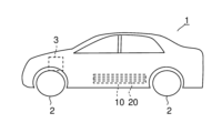
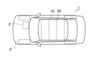
- a side view showing an electric vehicle equipped with a power storage device according to a first embodiment of the present invention A top view showing an electric vehicle equipped with a power storage device according to a first embodiment of the present invention
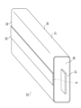
- a perspective view showing a power storage device according to a first embodiment of the present invention A side sectional view showing a power storage device according to a first embodiment of the present invention
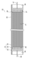
- a front sectional view showing a power storage device according to a first embodiment of the present invention Detailed view of H section in Figure 5
- a side sectional view showing a power storage device according to a second embodiment of the present invention A perspective view showing a power storage device according to a third embodiment of the present invention
- FIGS. 1 and 2 show a side view and a top view of an electric vehicle 1 including an electricity storage device 10 according to the first embodiment.
- the electric vehicle 1 includes a drive motor 3 as a power source for driving wheels 2.
- a power storage device 10 is installed under the floor of the body of the electric vehicle 1 as a drive source that supplies power to the drive motor 3.
- the power storage device 10 may be installed on the roof of the electric vehicle 1, or may be installed inside the seat.
- the power storage device 10 is formed by enclosing the power storage member 20 in a packaging container 30.
- the power storage member 20 is formed of a power storage element 21 in which a plurality of positive electrode plates and negative electrode plates are laminated in order with an insulating separator in between.
- An electrolyte is arranged between the positive electrode plate and the negative electrode plate.
- the electrolyte consists of an electrolytic solution.
- a solid electrolyte may be used as the electrolyte.
- Lead terminals 27 and 28 made of metal are connected to the positive electrode plate and the negative electrode plate, respectively.
- the packaging container 30 has a cylindrical body 31 with a substantially rectangular cross section that is open at both ends in the axial direction, and a closing portion 36 that closes both ends of the body 31 in the axial direction.
- the closing portion 36 is formed of a resin block. Electrodes 37 and 38 to which lead terminals 27 and 28 are connected pass through the closed portion 36 .
- the closed portion 36 through which the electrodes 37 and 38 penetrate can be formed. Further, by disposing the electrodes 37 and 38 in a recess formed on the circumferential surface of the closing portion 36 and thermally bonding them to the closing portion 36, it is possible to form the closing portion 36 through which the electrodes 37 and 38 penetrate.
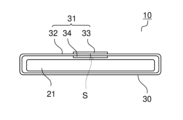
- the body portion 31 has a cylindrical portion 32, an outer tape 33, and an inner tape 34.
- the cylindrical portion 32 is arranged in a cylindrical shape with the end surfaces S of the laminated film 40 (see FIGS. 5 and 6) facing each other.
- the outer tape 33 is adhered to the outer surface of the cylindrical portion 32 and covers the abutted end surfaces S of the cylindrical portion 32.
- the inner surface tape 34 is adhered to the inner surface of the cylindrical portion 32 and covers the abutted end surfaces S of the cylindrical portion 32.
- the outer tape 33 and the inner tape 34 prevent water vapor from entering into the packaging container 30 through the gap between the opposing end surfaces S of the cylindrical portion 32 .
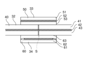
- FIG. 6 shows a detailed view of the H section in FIG. 5.
- the cylindrical portion 32 is disposed so that the end surfaces S of the laminated film 40 are abutted against each other, and has a base material layer 41, a barrier layer 42 (first barrier layer), and a heat-adhesive resin layer 43 in order from the outer surface side.
- the base material layer 41 is formed of a resin film such as nylon (PA) or polyethylene terephthalate (PET). In order to improve pinhole resistance, insulation properties, etc., the base material layer 41 may be formed by laminating a plurality of resin films made of different materials, such as nylon and polyethylene terephthalate.
- the thickness of the base material layer 41 is, for example, 5 to 1000 ⁇ m, preferably 5 to 30 ⁇ m.
- the barrier layer 42 is formed of an oxide vapor deposited film (silica, alumina, etc.), a metal vapor deposited film (aluminum, etc.), or a metal foil (aluminum, aluminum alloy, stainless steel, titanium, etc.).
- the barrier layer 42 prevents water vapor from entering the packaging container 30.
- the thickness of the barrier layer 42 of the vapor-deposited film is, for example, several nm to several ⁇ m.
- the thickness of the metal foil barrier layer 42 is, for example, 5 to 1000 ⁇ m, preferably 10 to 200 ⁇ m.
- the thermoadhesive resin layer 43 is formed of thermoplastic resin and is thermally bonded to the outer surface of the closing portion 36.
- the thermal adhesive resin layer 43 linear low-density polyethylene (LLDPE), low-density polyethylene (LDPE), high-density polyethylene (HDPE), polypropylene (PP), acid-modified polypropylene, acid-modified polyethylene, polyethylene terephthalate (PET) is used. , polybutylene terephthalate (PBT), etc. can be used.
- the thickness of the thermoadhesive resin layer 43 is, for example, 10 to 200 ⁇ m. Note that the base material layer 41 and the thermoadhesive resin layer 43 are formed by dry lamination or extrusion lamination on the barrier layer 42 of metal foil or on the film provided with the barrier layer 42 of vapor deposited film.
- the outer tape 33 is formed of a laminated film 50, and has a base layer 51, a barrier layer 52 (second barrier layer), and an adhesive layer 53 (first adhesive layer) in order from the outer surface side.
- the base material layer 51 is made of linear low-density polyethylene (LLDPE), low-density polyethylene (LDPE), high-density polyethylene (HDPE), polypropylene (PP), acid-modified polypropylene, acid-modified polyethylene, polyethylene terephthalate (PET), or polyethylene terephthalate (PET). It is formed from a resin film such as butylene terephthalate (PBT).
- the thickness of the base material layer 51 is, for example, 5 to 1000 ⁇ m.
- the barrier layer 52 (second barrier layer) is formed of an oxide vapor deposited film (silica, alumina, etc.), a metal vapor deposited film (aluminum, etc.), or a metal foil (aluminum, aluminum alloy, stainless steel, titanium, etc.).
- the barrier layer 52 prevents water vapor from entering the packaging container 30 from above the outer tape 33.
- the thickness of the barrier layer 52 of the vapor-deposited film is, for example, several nm to several ⁇ m.
- the thickness of the metal foil barrier layer 52 is, for example, 5 to 1000 ⁇ m, preferably 10 to 200 ⁇ m.
- the adhesive layer 53 is made of linear low density polyethylene (LLDPE), low density polyethylene (LDPE), high density polyethylene (HDPE), polypropylene (PP), acid modified polypropylene, acid modified polyethylene, polyethylene terephthalate (PET), polybutylene terephthalate. (PBT) or the like.
- the thickness of the adhesive layer 53 is, for example, 5 to 100 ⁇ m.
- the base material layer 51 and the thermoadhesive resin layer 53 are formed by dry lamination or extrusion lamination on the barrier layer 52 of metal foil or on the film provided with the barrier layer 52 of vapor deposited film.
- the outer tape 33 is bonded to the cylindrical portion 32 by the adhesive layer 53 by disposing the outer tape 33 so as to cover the opposing end surfaces S of the cylindrical portion 32 and bonding them under heat. This prevents the end surface S of the laminated film 40 from being exposed.
- the adhesive layer 53 includes linear low-density polyethylene (LLDPE), low-density polyethylene (LDPE), high-density polyethylene (HDPE), polypropylene (PP), acid-modified polypropylene, and acid-modified polyethylene, which are used as thermal adhesive resins.
- LLDPE linear low-density polyethylene
- LDPE low-density polyethylene
- HDPE high-density polyethylene
- PP polypropylene
- acid-modified polypropylene and acid-modified polyethylene
- thermal adhesive resins polyethylene, polyethylene terephthalate (PET), polybutylene terephthalate (PBT), etc.
- PET polyethylene terephthalate
- PBT polybutylene terephthalate
- the adhesive layer 53 may be made of urethane-based, epoxy-based, acrylic-based, polyester-based adhesive, or the like.
- the inner surface tape 34 is formed of a laminated film 60, and has a base material layer 61, a barrier layer 62, and an adhesive layer 63 (second adhesive layer) in order from the inner surface side.
- the inner surface tape 34 is adhered to the cylindrical portion 32 by the adhesive layer 63 . Further, the base material layer 61 is adhered to the circumferential surface of the closing portion 36 .
- the base material layer 61 is made of linear low density polyethylene (LLDPE), low density polyethylene (LDPE), high density polyethylene (HDPE), polypropylene (PP), acid modified polypropylene, acid modified polyethylene, polyethylene terephthalate (PET), polybutylene. It is formed from a resin film such as terephthalate (PBT).
- the thickness of the base material layer 41 is, for example, 5 to 100 ⁇ m.
- the barrier layer 62 is formed of an oxide vapor deposited film (silica, alumina, etc.), a metal vapor deposited film (aluminum, etc.), or a metal foil (aluminum, aluminum alloy, stainless steel, titanium, etc.).
- the barrier layer 62 can further prevent water vapor from entering the packaging container 30 through the gap between the end faces S.
- the thickness of the barrier layer 62 of the vapor-deposited film is, for example, several nm to several ⁇ m.
- the thickness of the metal foil barrier layer 62 is, for example, 5 to 1000 ⁇ m, preferably 10 to 200 ⁇ m.
- the adhesive layer 63 is made of linear low density polyethylene (LLDPE), low density polyethylene (LDPE), high density polyethylene (HDPE), polypropylene (PP), acid modified polypropylene, acid modified polyethylene, polyethylene terephthalate (PET), polybutylene terephthalate. (PBT) or the like.
- the thickness of the adhesive layer 63 is, for example, 10 to 100 ⁇ m.
- the base material layer 61 and the thermoadhesive resin layer 63 are formed by dry lamination or extrusion lamination on the barrier layer 62 of metal foil or on the film provided with the barrier layer 62 of vapor deposited film.
- the inner tape 34 is bonded to the cylindrical portion 32 by the adhesive layer 63 by disposing the inner tape 34 so as to cover the opposing end surfaces S of the cylindrical portion 32 and bonding them under heat.
- the adhesive layer 63 a urethane-based, epoxy-based, acrylic-based, polyester-based adhesive, or the like may be used.
- the barrier layer 62 is formed of metal foil or a metal vapor deposited film and is exposed on the side end surface of the inner tape 34, there is a risk of a short circuit of the electricity storage member 20. Therefore, as shown in FIG. 6, the barrier layer 62 is formed to have a narrow width in the circumferential direction with respect to the base material layer 61 and the adhesive layer 63 by etching the inner surface tape 34 or the like. Thereby, the side end surface of the barrier layer 62 is covered with the base material layer 61 and the adhesive layer 63, and short circuits of the power storage member 20 can be prevented.
- the barrier layer 62 may be omitted and a single-layer inner tape 34 having the adhesive layer 63 may be used. Furthermore, if the outer tape 33 provides a higher level of water vapor barrier, the inner tape 34 may be omitted.
- the packaging container 30 is formed by adhering the outer tape 33 to the outer surface of the cylindrical portion 32 where the end surfaces S of the laminated film 40 are abutted against each other.
- the cylindrical part 32 has a base material layer 41 laminated on the outer surface of the barrier layer 42 (first barrier layer), and the outer tape 33 has a resin adhesive layer 53 (second barrier layer) laminated on the inner surface of the barrier layer 52 (second barrier layer). 1 adhesive layer) is laminated.
- the exposed area of the heat-adhesive resin layer 43 of the laminated film 40 forming the cylindrical part 32 can be reduced, and the gap between the end surfaces S of the laminated film 40 is covered with the outer tape 33.
- water vapor intrusion into the interior of the electricity storage device 10 is reduced.
- volatilization of the electrolyte in the electricity storage member 20 is suppressed. Therefore, the characteristics of power storage device 10 can be maintained for a long period of time.
- the flange portion does not protrude from the periphery of the electricity storage device 10 as in the conventional example. Therefore, it is possible to omit the step of bending the flange portion onto the circumferential surface in order to prevent a decrease in volumetric efficiency when a plurality of power storage devices 10 are arranged in parallel. Thereby, the number of manufacturing steps for the power storage device 10 can be reduced.
- the inner surface tape 34 having the resin adhesive layer 63 (second adhesive layer) on the outer surface side is adhered to the inner surface of the cylindrical portion 32, the gap between the end surfaces S of the cylindrical portion 32 is filled by the inner surface tape 34. shielded. Therefore, it is possible to further suppress the infiltration of water vapor into the interior of the power storage device 10 and the volatilization of the electrolyte in the power storage member 20.
- the inner surface tape 34 does not include the barrier layer 62 of metal foil and metal vapor deposition film, short circuits of the electricity storage member 20 can be prevented.
- the circumferential width of the barrier layer 62 is narrower than the adhesive layer 63 on the outer surface side and the resin base layer 61 on the inner surface side. . As a result, metal is not exposed on the end face of the inner tape 34, so that short circuits of the power storage member 20 can be prevented.
- the adhesive layer 53 (first adhesive layer) of the outer tape 33 is made of resin with high water vapor barrier properties such as linear low-density polyethylene (LLDPE), low-density polyethylene (LDPE), high-density polyethylene (HDPE), polypropylene ( PP), acid-modified polypropylene, and acid-modified polyethylene.
- LLDPE linear low-density polyethylene
- LDPE low-density polyethylene
- HDPE high-density polyethylene
- PP polypropylene
- acid-modified polypropylene and acid-modified polyethylene.
- the closing portion 36 is formed by a resin block through which the electrodes 37 and 38 pass, and the cylindrical portion 32 has a heat-adhesive resin layer 43 that is thermally bonded to the outer surface of the block. Thereby, both axial ends of the body portion 31 can be easily sealed.
- the power storage member 20 is formed by connecting a plurality of power storage cells 25 in which a power storage element 21 in which an electrolyte is arranged between a positive electrode plate and a negative electrode plate is enclosed. Thereby, it is possible to easily realize the power storage device 10 in which the power storage member 20 made up of the plurality of power storage cells 25 filled with an electrolytic solution is enclosed in the packaging container 30.
- FIG. 7 shows a side sectional view of the electricity storage device 10 of the second embodiment.
- the same reference numerals are given to the same parts as in the first embodiment shown in FIGS. 1 to 6 described above.
- the closing portion 36 of the packaging container 30 is formed of metal. Other parts are the same as those in the first embodiment.
- the closing part 36 of the packaging container 30 is formed of a metal block, and the electrodes 37 and 38 are formed integrally with the closing part 36.
- the body portion 31 is bonded to the block forming the closing portion 36 by a heat-adhesive resin layer 43.
- the thermal adhesive resin layer 43 uses a resin with low adhesiveness to metal members, such as linear low-density polyethylene (LLDPE), low-density polyethylene (LDPE), or polypropylene (PP),
- LLDPE linear low-density polyethylene
- LDPE low-density polyethylene
- PP polypropylene
- the closing portion 36 and the cylindrical portion can be thermally bonded via the film.
- the metal adhesive film for example, a single layer film of acid-modified polypropylene, a multilayer film of acid-modified polypropylene and polypropylene, etc. can be used.
- the cylindrical portion 32 similarly to the first embodiment, the cylindrical portion 32 has the base material layer 41 laminated on the outer surface of the barrier layer 42, and the outer tape 33 has a resin adhesive layer 53 on the inner surface of the barrier layer 52. are laminated. This makes it possible to reduce the exposed area of the heat-adhesive resin layer 43 of the cylindrical portion 32, thereby suppressing infiltration of water vapor and volatilization of the electrolytic solution. Therefore, the characteristics of power storage device 10 can be maintained for a long period of time.
- the closing portion 36 is formed of a metal block integral with the electrodes 37 and 38, and the cylindrical portion 32 has a heat-adhesive resin layer 43 that is thermally bonded to the outer surface of the block. Thereby, both axial ends of the body portion 31 can be easily sealed.
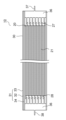
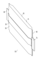
- FIGS. 8 and 9 show a perspective view and a front sectional view of the electricity storage device 10 of the third embodiment.
- the power storage member 20 in the packaging container 30 is formed of a power storage element in which an electrolyte is arranged between a positive electrode plate and a negative electrode plate.
- Other parts are the same as those in the first embodiment.
- the power storage element 21 constituting the power storage member 20 is formed by arranging a positive electrode plate and a negative electrode plate (both not shown) facing each other with an insulating separator (not shown) interposed therebetween.
- An electrolyte is arranged between the positive electrode plate and the negative electrode plate.
- the electrolyte consists of an electrolytic solution, and is filled inside the packaging container 30.
- a solid electrolyte may be used as the electrolyte.
- Electrodes 37 and 38 made of metal are connected to the positive electrode plate and the negative electrode plate, respectively.
- the packaging container 30 includes a body portion 31 having a cylindrical portion 32, an outer tape 33, and an inner tape 34.
- the cylindrical portion 32, the outer tape 33, and the inner tape 34 are formed of the laminated films 40, 50, and 60 shown in FIG. 6 described above. Both ends in the axial direction of the body portion 31 are closed by closing portions 36 which are formed by thermally bonding the opposing heat-adhesive resin layers 43 (see FIG. 6) of the cylindrical portion 32.
- the electrodes 37 and 38 are sandwiched between the heat-adhesive resin layer 43 of the closing portion 36 and protrude from the body portion 31 in the axial direction.
- the cylindrical portion 32 similarly to the first embodiment, the cylindrical portion 32 has the base material layer 41 laminated on the outer surface of the barrier layer 42, and the outer tape 33 has a resin adhesive layer 53 on the inner surface of the barrier layer 52. are laminated. This makes it possible to reduce the exposed area of the heat-adhesive resin layer 43 of the cylindrical portion 32, thereby suppressing infiltration of water vapor and volatilization of the electrolytic solution. Therefore, the characteristics of power storage device 10 can be maintained for a long period of time.
- the closing portion 36 is formed by thermally bonding the thermally adhesive resin layer 43 at the end of the cylindrical portion 32, and sandwiches the electrodes 37 and 38 provided on the power storage member 20. Thereby, both axial ends of the body portion 31 can be easily sealed.
- the power storage member 20 is a power storage element 21 in which an electrolyte is arranged between a positive electrode plate and a negative electrode plate, it is possible to easily realize a power storage device 10 in which a power storage element 21 filled with an electrolytic solution is enclosed.
- the cross-sectional shape of the body 31 of the packaging container 30 may be other shapes such as a polygon, circle, or ellipse.
- the power storage member 20 may be a bipolar type in which a plurality of power storage elements 21 are stacked and connected in series, and metal tabs provided on both end faces in the stacking direction are connected to the electrodes 37 and 38.
- the power storage member 20 that supplies power to the drive motor 3 is made of a secondary battery, it may be a capacitor (an electrolytic capacitor, an electric double layer capacitor, a lithium ion capacitor, etc.).
Landscapes
- Chemical & Material Sciences (AREA)
- Chemical Kinetics & Catalysis (AREA)
- Electrochemistry (AREA)
- General Chemical & Material Sciences (AREA)
- Engineering & Computer Science (AREA)
- Power Engineering (AREA)
- Microelectronics & Electronic Packaging (AREA)
- Inorganic Chemistry (AREA)
- Manufacturing & Machinery (AREA)
- Electric Double-Layer Capacitors Or The Like (AREA)
- Sealing Battery Cases Or Jackets (AREA)
- Battery Mounting, Suspending (AREA)
Abstract
蓄電部材20を包装容器30に封入した蓄電デバイス10において、包装容器30が筒状の胴部31の両端を閉塞部36により閉塞して形成され、胴部31が、積層フィルム40の端面を突き合わせて配される筒状部32と、筒状部32の外面に接着して前記端面上を覆う外面テープ33とを有し、筒状部32が樹脂製の基材層41の内面側に第1バリア層42を積層され、外面テープ33が第2バリア層52の内面側に樹脂製の接着層53を積層される。
Description
本発明は、包装容器により密封される蓄電デバイス及びそれを備えた電動自動車に関する。
近年、環境対策や省資源化等の観点から、駆動力の少なくとも一部をモータが供給する電動自動車が注目されている。この電動自動車には、電気自動車(EV)、ハイブリッド自動車(HEV)、プラグインハイブリッド自動車(PHEV)等がある。電気自動車はモータのみを動力源とし、ハイブリッド自動車及びプラグインハイブリッド自動車はモータ及びエンジンを動力源とする。
電動自動車に搭載される従来の蓄電デバイスは特許文献1に開示される。この蓄電デバイスは直列接続及び並列接続によって複数並設され、電動自動車の床下等に設置される。蓄電デバイスは二次電池から成る複数の単電池を備える。また、単電池はバイポーラ型に構成されてもよい。複数の単電池は積層され、積層方向の両端面に正極電極及び負極電極がそれぞれ接続される。蓄電デバイスは包装容器により覆われ、正極電極及び負極電極を引き出した状態で密封される。
包装容器は熱接着性樹脂層を有した1つまたは2つのラミネートフィルムにより形成される。一方のラミネートフィルムには積層された単電池を収納する収納部が凹設され、収納部の周囲にフランジ部が設けられる。包装容器が2つのラミネートフィルムからなる場合には、フランジ部で一方のラミネートフィルムの熱接着性樹脂層と他方のラミネートフィルムの熱接着性樹脂層とが対向して熱接着され、包装容器が密封される。
しかしながら、上記従来の蓄電デバイスによると、2つのラミネートフィルムの熱接着性樹脂層が対向して熱接着されるため、フランジ部の周囲に両方の熱接着性樹脂層の端面が露出する。このため、熱接着性樹脂層の端面から包装容器内に水蒸気が浸入する場合や包装容器から電解液が揮発する場合があり、蓄電デバイスの特性の長期保持が困難になる問題があった。
本発明は、特性を長期保持できる蓄電デバイス及びそれを備えた電動自動車を提供することを目的とする。
上記目的を達成するために本発明は、蓄電部材を包装容器に封入した蓄電デバイスにおいて、前記包装容器が筒状の胴部の両端を閉塞部により閉塞して形成され、前記胴部が、積層フィルムの端面を突き合わせて配される筒状部と、前記筒状部の外面に接着して前記端面上を覆う外面テープとを有し、前記筒状部が樹脂製の基材層の内面側に第1バリア層を積層され、前記外面テープが第2バリア層の内面側に樹脂製の第1接着層を積層されることを特徴としている。
また本発明は上記構成の蓄電デバイスにおいて、前記胴部が前記筒状部の内面に接着して前記端面上を覆う内面テープを有し、前記内面テープが少なくとも外面側に樹脂製の第2接着層を有することを特徴としている。
また本発明は上記構成の蓄電デバイスにおいて、前記内面テープが金属箔及び金属蒸着膜を含まないことを特徴としている。
また本発明は上記構成の蓄電デバイスにおいて、前記内面テープが外面側に配した前記第2接着層及び内面側に配した樹脂よりも周方向の幅の狭い金属箔または金属蒸着膜を有することを特徴としている。
また本発明は上記構成の蓄電デバイスにおいて、前前記第1接着層が直鎖状低密度ポリエチレン、低密度ポリエチレン、高密度ポリエチレン、ポリプロピレン、酸変性ポリプロピレン、酸変性ポリエチレンのいずれかにより形成されることを特徴としている。
また本発明は上記構成の蓄電デバイスにおいて、前記閉塞部が樹脂製のブロックにより形成されるとともに前記ブロックを電極が貫通し、前記筒状部が前記ブロックの外面に熱接着される熱接着性樹脂層を有することを特徴としている。
また本発明は上記構成の蓄電デバイスにおいて、前記閉塞部が金属製のブロックにより形成されるとともに前記ブロックと一体に電極が形成され、前記筒状部が前記ブロックの外面に熱接着される熱接着性樹脂層を有することを特徴としている。
また本発明は上記構成の蓄電デバイスにおいて、前記筒状部が内面に熱接着性樹脂層を有し、前記閉塞部は前記筒状部の端部の前記熱接着性樹脂層を熱接着して形成され、前記蓄電部材に設けた電極を挟むことを特徴としている。
また本発明は上記構成の蓄電デバイスにおいて、前記蓄電部材が、正極板と負極板との間に電解質を配した蓄電素子であることを特徴としている。
また本発明の電動自動車は、上記各構成の蓄電デバイスを備えたことを特徴としている。
本発明によると、包装容器が積層フィルムの端面を突き合わせた筒状部の外面に外面テープを接着して形成される。筒状部は第1バリア層の外面に基材層を積層され、外面テープは第2バリア層の内面側に樹脂製の接着層を積層される。これにより、筒状部を形成する積層フィルムの熱接着性樹脂層の露出面積を小さくすることができ、水蒸気の浸入や電解液の揮発が抑制される。従って、蓄電デバイスの特性を長期保持することができる。
<第1実施形態>
以下に図面を参照して本発明の実施形態を説明する。図1、図2は第1実施形態の蓄電デバイス10を備えた電動自動車1の側面図及び上面図を示している。電動自動車1は車輪2を駆動する動力源として駆動モータ3を備えている。電動自動車1の車体のフロア下には駆動モータ3に電力を供給する駆動源として蓄電デバイス10が設置される。蓄電デバイス10を電動自動車1のルーフに設置してもよく、座席内に設置してもよい。
以下に図面を参照して本発明の実施形態を説明する。図1、図2は第1実施形態の蓄電デバイス10を備えた電動自動車1の側面図及び上面図を示している。電動自動車1は車輪2を駆動する動力源として駆動モータ3を備えている。電動自動車1の車体のフロア下には駆動モータ3に電力を供給する駆動源として蓄電デバイス10が設置される。蓄電デバイス10を電動自動車1のルーフに設置してもよく、座席内に設置してもよい。
図3、図4、図5は蓄電デバイス10の斜視図、側面断面図及び正面断面図を示している。蓄電デバイス10は蓄電部材20を包装容器30に封入して形成される。蓄電部材20は複数の正極板及び負極板を絶縁体のセパレータを挟んで順に積層した蓄電素子21により形成される。正極板と負極板との間には電解質が配される。本実施形態では電解質が電解液から成っている。電解質として固体電解質を用いてもよい。正極板及び負極板にはそれぞれ金属から成るリード端子27、28が接続される。
包装容器30は、軸方向の両端を開放した断面略矩形の筒状の胴部31と、胴部31の軸方向両端を閉塞する閉塞部36と、を有している。閉塞部36は樹脂製のブロックにより形成される。閉塞部36にはリード端子27、28を接続される電極37、38が貫通する。
例えば、樹脂製のブロックの半体で電極37、38を挟み、ブロックの半体を熱接着することにより、電極37、38が貫通した閉塞部36を形成することができる。また、閉塞部36の周面上に凹設した凹部に電極37、38を配して閉塞部36と熱接着することにより、電極37、38が貫通した閉塞部36を形成することができる。
胴部31は筒状部32、外面テープ33及び内面テープ34を有している。筒状部32は積層フィルム40(図5、図6参照)の端面Sを突き合わせて筒状に配される。外面テープ33は筒状部32の外面に接着して筒状部32の突き合わせた端面S上を覆う。内面テープ34は筒状部32の内面に接着して筒状部32の突き合わせた端面S上を覆う。外面テープ33及び内面テープ34により、筒状部32の対向する端面S間の隙間を介して包装容器30内へ水蒸気が浸入することが防止される。
図6は図5のH部詳細図を示している。筒状部32は積層フィルム40の端面Sを突き合わせて配され、外面側から順に基材層41、バリア層42(第1バリア層)、熱接着性樹脂層43を有している。
基材層41はナイロン(PA)、ポリエチレンテレフタレート(PET)等の樹脂フィルムにより形成される。耐ピンホール性、絶縁性等の向上のために、例えばナイロン及びポリエチレンテレフタレート等の異なる素材の樹脂フィルムを複数積層して基材層41を形成してもよい。基材層41の厚みは例えば、5~1000μm、好ましくは5~30μmである。
バリア層42は、酸化物蒸着膜(シリカ、アルミナ等)、金属蒸着膜(アルミニウム等)、または金属箔(アルミニウム、アルミニウム合金、ステンレス鋼、チタン等)により形成される。バリア層42により包装容器30内への水蒸気の浸入が防止される。蒸着膜のバリア層42の厚みは例えば、数nm~数μmである。金属箔のバリア層42の厚みは例えば、5~1000μm、好ましくは10~200μmである。
熱接着性樹脂層43は熱可塑性の樹脂により形成され、閉塞部36の外面に熱接着される。熱接着性樹脂層43として、直鎖状低密度ポリエチレン(LLDPE)、低密度ポリエチレン(LDPE)、高密度ポリエチレン(HDPE)、ポリプロピレン(PP)、酸変性ポリプロピレン、酸変性ポリエチレン、ポリエチレンテレフタレート(PET)、ポリブチレンテレフタレート(PBT)等を用いることができる。熱接着性樹脂層43の厚みは例えば10~200μmである。尚、金属箔のバリア層42上または蒸着膜のバリア層42を設けたフィルム上に、基材層41及び熱接着性樹脂層43がドライラミネートまたは押出ラミネートにより形成される。
外面テープ33は積層フィルム50により形成され、外面側から順に基材層51、バリア層52(第2バリア層)、接着層53(第1接着層)を有している。基材層51は、直鎖状低密度ポリエチレン(LLDPE)、低密度ポリエチレン(LDPE)、高密度ポリエチレン(HDPE)、ポリプロピレン(PP)、酸変性ポリプロピレン、酸変性ポリエチレン、ポリエチレンテレフタレート(PET)、ポリブチレンテレフタレート(PBT)等の樹脂フィルムにより形成される。基材層51の厚みは例えば、5~1000μmである。
バリア層52(第2バリア層)は、酸化物蒸着膜(シリカ、アルミナ等)、金属蒸着膜(アルミニウム等)、または金属箔(アルミニウム、アルミニウム合金、ステンレス鋼、チタン等)により形成される。バリア層52により外面テープ33上から包装容器30内への水蒸気の浸入が防止される。蒸着膜のバリア層52の厚みは例えば、数nm~数μmである。金属箔のバリア層52の厚みは例えば、5~1000μm、好ましくは10~200μmである。
接着層53は直鎖状低密度ポリエチレン(LLDPE)、低密度ポリエチレン(LDPE)、高密度ポリエチレン(HDPE)、ポリプロピレン(PP)、酸変性ポリプロピレン、酸変性ポリエチレン、ポリエチレンテレフタレート(PET)、ポリブチレンテレフタレート(PBT)等により形成される。接着層53の厚みは例えば5~100μmである。尚、金属箔のバリア層52上または蒸着膜のバリア層52を設けたフィルム上に、基材層51及び熱接着性樹脂層53がドライラミネートまたは押出ラミネートにより形成される。
筒状部32の対向する端面Sを覆うように外面テープ33を配して加熱圧着することにより、接着層53によって外面テープ33が筒状部32に接着される。これにより、積層フィルム40の端面Sの露出が防止される。
尚、接着層53には、熱接着性樹脂として用いられる直鎖状低密度ポリエチレン(LLDPE)、低密度ポリエチレン(LDPE)、高密度ポリエチレン(HDPE)、ポリプロピレン(PP)、酸変性ポリプロピレン、酸変性ポリエチレン、ポリエチレンテレフタレート(PET)、ポリブチレンテレフタレート(PBT)等を用いることができる。
その中でも水蒸気バリア性の高い樹脂である直鎖状低密度ポリエチレン(LLDPE)、低密度ポリエチレン(LDPE)、高密度ポリエチレン(HDPE)、ポリプロピレン(PP)、酸変性ポリプロピレン、酸変性ポリエチレン等を用いることで、接着層53を介した包装容器30内への水蒸気の浸入が抑制され、蓄電デバイス10の特性を長期保持することができる。尚、接着層53としてウレタン系、エポキシ系、アクリル系、ポリエステル系等の接着剤を用いてもよい。
内面テープ34は積層フィルム60により形成され、内面側から順に基材層61、バリア層62、接着層63(第2接着層)を有している。接着層63により内面テープ34が筒状部32に接着される。また、基材層61は閉塞部36の周面に接着される。
基材層61は直鎖状低密度ポリエチレン(LLDPE)、低密度ポリエチレン(LDPE)、高密度ポリエチレン(HDPE)、ポリプロピレン(PP)、酸変性ポリプロピレン、酸変性ポリエチレン、ポリエチレンテレフタレート(PET)、ポリブチレンテレフタレート(PBT)等の樹脂フィルムにより形成される。基材層41の厚みは例えば、5~100μmである。
バリア層62は、酸化物蒸着膜(シリカ、アルミナ等)、金属蒸着膜(アルミニウム等)、または金属箔(アルミニウム、アルミニウム合金、ステンレス鋼、チタン等)により形成される。バリア層62により端面S間の隙間を介して包装容器30内へ水蒸気が浸入することをより防止することができる。蒸着膜のバリア層62の厚みは例えば、数nm~数μmである。金属箔のバリア層62の厚みは例えば、5~1000μm、好ましくは10~200μmである。
接着層63は直鎖状低密度ポリエチレン(LLDPE)、低密度ポリエチレン(LDPE)、高密度ポリエチレン(HDPE)、ポリプロピレン(PP)、酸変性ポリプロピレン、酸変性ポリエチレン、ポリエチレンテレフタレート(PET)、ポリブチレンテレフタレート(PBT)等により形成される。接着層63の厚みは例えば10~100μmである。尚、金属箔のバリア層62上または蒸着膜のバリア層62を設けたフィルム上に、基材層61及び熱接着性樹脂層63がドライラミネートまたは押出ラミネートにより形成される。
筒状部32の対向する端面Sを覆うように内面テープ34を配して加熱圧着することにより、接着層63によって内面テープ34が筒状部32に接着される。接着層63としてウレタン系、エポキシ系、アクリル系、ポリエステル系等の接着剤を用いてもよい。
ここで、バリア層62が金属箔または金属蒸着膜により形成された場合に内面テープ34の側端面上に露出すると、蓄電部材20の短絡の虞がある。このため、図6に示すように内面テープ34のエッチング等によりバリア層62が基材層61及び接着層63に対して周方向の幅を狭く形成される。これにより、バリア層62の側端面が基材層61及び接着層63に覆われ、蓄電部材20の短絡を防止することができる。
尚、外面テープ33により水蒸気を十分遮断できる場合には、バリア層62を省いて接着層63を有した単層の内面テープ34を用いてもよい。更に外面テープ33により水蒸気をより高いレベルで遮断できる場合には、内面テープ34を省いてもよい。
本実施形態によると、包装容器30が積層フィルム40の端面Sを突き合わせた筒状部32の外面に外面テープ33を接着して形成される。筒状部32はバリア層42(第1バリア層)の外面に基材層41を積層され、外面テープ33はバリア層52(第2バリア層)の内面側に樹脂製の接着層53(第1接着層)を積層される。
これにより、筒状部32を形成する積層フィルム40の熱接着性樹脂層43の露出面積を小さくできるとともに、積層フィルム40の端面S間の隙間が外面テープ33で覆われる。このため、従来例のようにフランジ部上に熱接着性樹脂層が露出する包装容器や、合掌貼りのシール部を備えたピロー型の包装容器に比べて、蓄電デバイス10内部への水蒸気の浸入や蓄電部材20の電解液の揮発が抑制される。従って、蓄電デバイス10の特性を長期保持することができる。
加えて、従来例のようなフランジ部が蓄電デバイス10の周囲から突出しない。このため、蓄電デバイス10を複数並設した際の容積効率低下を防止するためにフランジ部を周面上に折曲する工程を省くことができる。これにより、蓄電デバイス10の製造工数を削減することができる。
また、外面側に樹脂製の接着層63(第2接着層)を有する内面テープ34が筒状部32の内面に接着されるので、筒状部32の端面S間の隙間が内面テープ34により遮蔽される。従って、蓄電デバイス10内部への水蒸気の浸入や蓄電部材20の電解液の揮発をより抑制することができる。
また、内面テープ34が金属箔及び金属蒸着膜のバリア層62を含まない場合に、蓄電部材20の短絡を防止することができる。
また、内面テープ34が金属箔及び金属蒸着膜のバリア層62を含むの場合に、外面側の接着層63及び内面側の樹脂の基材層61よりもバリア層62の周方向の幅が狭い。これにより、内側テープ34の端面において金属が露出しないため、蓄電部材20の短絡を防止することができる。
また、外面テープ33の接着層53(第1接着層)が水蒸気バリア性の高い樹脂である直鎖状低密度ポリエチレン(LLDPE)、低密度ポリエチレン(LDPE)、高密度ポリエチレン(HDPE)、ポリプロピレン(PP)、酸変性ポリプロピレン、酸変性ポリエチレンにより形成される。これにより、接着層53を介した包装容器30内への水蒸気の浸入が抑制され、蓄電デバイス10の特性を長期保持することができる。
また、電極37、38が貫通する樹脂製のブロックにより閉塞部36が形成され、筒状部32がブロックの外面に熱接着される熱接着性樹脂層43を有する。これにより、胴部31の軸方向両端部を容易に密閉することができる。
また、蓄電部材20は、正極板と負極板との間に電解質を配した蓄電素子21が封入される蓄電セル25を複数接続して形成される。これにより、電解液を充填される複数の蓄電セル25から成る蓄電部材20を包装容器30に封入した蓄電デバイス10を容易に実現することができる。
<第2実施形態>
次に、図7は第2実施形態の蓄電デバイス10の側面断面図を示している。説明の便宜上、前述の図1~図6に示す第1実施形態と同様の部分には同一の符号を付している。本実施形態は包装容器30の閉塞部36が金属により形成される。その他の部分は第1実施形態と同様である。
次に、図7は第2実施形態の蓄電デバイス10の側面断面図を示している。説明の便宜上、前述の図1~図6に示す第1実施形態と同様の部分には同一の符号を付している。本実施形態は包装容器30の閉塞部36が金属により形成される。その他の部分は第1実施形態と同様である。
包装容器30の閉塞部36は金属製のブロックにより形成され、電極37、38は閉塞部36と一体に形成される。胴部31は閉塞部36を形成するブロックと熱接着性樹脂層43により接着される。この時、熱接着性樹脂層43として酸変性ポリプロピレンや酸変性ポリエチレンを用いると、閉塞部36を形成する金属部材に対する接着性が高いためより望ましい。
また、熱接着性樹脂層43が直鎖状低密度ポリエチレン(LLDPE)、低密度ポリエチレン(LDPE)、ポリプロピレン(PP)などの金属部材に対する接着性が低い樹脂を使用する場合には、金属接着性フィルムを介して閉塞部36と筒状部を熱接着することができる。金属接着性フィルムとしては、例えば酸変性ポリプロピレン単層のフィルム、酸変性ポリプロピレンとポリプロピレンとの多層のフィルム等を使用することができる。
本実施形態によると、第1実施形態と同様に、筒状部32はバリア層42の外面に基材層41を積層され、外面テープ33はバリア層52の内面側に樹脂製の接着層53を積層される。これにより、筒状部32の熱接着性樹脂層43の露出面積を小さくして水蒸気の浸入及び電解液の揮発を抑制することができる。従って、蓄電デバイス10の特性を長期保持することができる。
また、閉塞部36が電極37、38と一体の金属製のブロックにより形成され、筒状部32がブロックの外面に熱接着される熱接着性樹脂層43を有する。これにより、胴部31の軸方向両端部を容易に密閉することができる。
<第3実施形態>
次に、図8、図9は第3実施形態の蓄電デバイス10の斜視図及び正面断面図を示している。説明の便宜上、前述の図1~図6に示す第1実施形態と同様の部分には同一の符号を付している。本実施形態は包装容器30内の蓄電部材20が正極板と負極板との間に電解質を配した蓄電素子により形成される。その他の部分は第1実施形態と同様である。
次に、図8、図9は第3実施形態の蓄電デバイス10の斜視図及び正面断面図を示している。説明の便宜上、前述の図1~図6に示す第1実施形態と同様の部分には同一の符号を付している。本実施形態は包装容器30内の蓄電部材20が正極板と負極板との間に電解質を配した蓄電素子により形成される。その他の部分は第1実施形態と同様である。
蓄電部材20を構成する蓄電素子21は正極板と負極板(いずれも不図示)とを絶縁体のセパレータ(不図示)を介して対向配置して形成される。正極板と負極板との間には電解質が配される。本実施形態では電解質が電解液から成り、包装容器30の内部に充填される。電解質として固体電解質を用いてもよい。正極板及び負極板にはそれぞれ金属から成る電極37、38が接続される。
包装容器30は筒状部32,外面テープ33及び内面テープ34を有した胴部31を備えている。筒状部32,外面テープ33及び内面テープ34は前述の図6に示す積層フィルム40、50、60により形成される。胴部31の軸方向両端は筒状部32の対向する熱接着性樹脂層43(図6参照)を熱接着した閉塞部36により閉塞される。電極37、38は閉塞部36の熱接着性樹脂層43間に挟まれ、胴部31から軸方向に突出する。
本実施形態によると、第1実施形態と同様に、筒状部32はバリア層42の外面に基材層41を積層され、外面テープ33はバリア層52の内面側に樹脂製の接着層53を積層される。これにより、筒状部32の熱接着性樹脂層43の露出面積を小さくして水蒸気の浸入及び電解液の揮発を抑制することができる。従って、蓄電デバイス10の特性を長期保持することができる。
また、閉塞部36は筒状部32の端部の熱接着性樹脂層43を熱接着して形成され、蓄電部材20に設けた電極37、38を挟む。これにより、胴部31の軸方向両端部を容易に密閉することができる。
また、蓄電部材20が正極板と負極板との間に電解質を配した蓄電素子21であるので、電解液を充填した蓄電素子21を封入した蓄電デバイス10を容易に実現することができる。
第1~第3実施形態において、包装容器30の胴部31の断面形状を多角形、円形、楕円形等の他の形状にしてもよい。また、蓄電部材20が、複数の蓄電素子21を積層して直列接続し、積層方向の両端面に設けた金属タブを電極37、38に接続したバイポーラ型であってもよい。また、駆動モータ3に電力を供給する蓄電部材20が二次電池から成るが、キャパシタ(電解コンデンサ、電気二重層キャパシタ、リチウムイオンキャパシタ等)であってもよい。
本発明によると、蓄電デバイス及び蓄電デバイスを搭載した電動自動車に広く利用可能である。
1 電動自動車
2 車輪
3 駆動モータ
10 蓄電デバイス
20 蓄電部材
21 蓄電素子
27、28 リード端子
30 包装容器
31 胴部
32 筒状部
33 外面テープ
34 内面テープ
36 閉塞部
37、38 電極
40、50、60 積層フィルム
41、51、61 基材層
42 バリア層(第1バリア層)
43 熱接着性樹脂層
52 バリア層(第2バリア層)
53 接着層(第1接着層)
62 バリア層
63 接着層(第2接着層)
2 車輪
3 駆動モータ
10 蓄電デバイス
20 蓄電部材
21 蓄電素子
27、28 リード端子
30 包装容器
31 胴部
32 筒状部
33 外面テープ
34 内面テープ
36 閉塞部
37、38 電極
40、50、60 積層フィルム
41、51、61 基材層
42 バリア層(第1バリア層)
43 熱接着性樹脂層
52 バリア層(第2バリア層)
53 接着層(第1接着層)
62 バリア層
63 接着層(第2接着層)
Claims (10)
- 蓄電部材を包装容器に封入した蓄電デバイスにおいて、前記包装容器が筒状の胴部の両端を閉塞部により閉塞して形成され、前記胴部が、積層フィルムの端面を突き合わせて配される筒状部と、前記筒状部の外面に接着して前記端面上を覆う外面テープとを有し、前記筒状部が樹脂製の基材層の内面側に第1バリア層を積層され、前記外面テープが第2バリア層の内面側に樹脂製の第1接着層を積層されることを特徴とする蓄電デバイス。
- 前記胴部が前記筒状部の内面に接着して前記端面上を覆う内面テープを有し、前記内面テープが少なくとも外面側に樹脂製の第2接着層を有することを特徴とする請求項1に記載の蓄電デバイス。
- 前記内面テープが金属箔及び金属蒸着膜を含まないことを特徴とする請求項2に記載の蓄電デバイス。
- 前記内面テープが外面側に配した前記第2接着層及び内面側に配した樹脂よりも周方向の幅の狭い金属箔または金属蒸着膜を有することを特徴とする請求項2に記載の蓄電デバイス。
- 前記第1接着層が直鎖状低密度ポリエチレン、低密度ポリエチレン、高密度ポリエチレン、ポリプロピレン、酸変性ポリプロピレン、酸変性ポリエチレンのいずれかにより形成されることを特徴とする請求項1または請求項2に記載の蓄電デバイス。
- 前記閉塞部が樹脂製のブロックにより形成されるとともに前記ブロックを電極が貫通し、前記筒状部が前記ブロックの外面に熱接着される熱接着性樹脂層を有することを特徴とする請求項1または請求項2に記載の蓄電デバイス。
- 前記閉塞部が金属製のブロックにより形成されるとともに前記ブロックと一体に電極が形成され、前記筒状部が前記ブロックの外面に熱接着される熱接着性樹脂層を有することを特徴とする請求項1または請求項2に記載の蓄電デバイス。
- 前記筒状部が内面に熱接着性樹脂層を有し、前記閉塞部は前記筒状部の端部の前記熱接着性樹脂層を熱接着して形成され、前記蓄電部材に設けた電極を挟むことを特徴とする請求項1または請求項2に記載の蓄電デバイス。
- 前記蓄電部材が、正極板と負極板との間に電解質を配した蓄電素子であることを特徴とする請求項1または請求項2に記載の蓄電デバイス。
- 請求項1または請求項2に記載の蓄電デバイスを備えたことを特徴とする電動自動車。
Applications Claiming Priority (2)
| Application Number | Priority Date | Filing Date | Title |
|---|---|---|---|
| JP2022110351A JP7276572B1 (ja) | 2022-07-08 | 2022-07-08 | 蓄電デバイス及び電動自動車 |
| JP2022-110351 | 2022-07-08 |
Publications (1)
| Publication Number | Publication Date |
|---|---|
| WO2024009786A1 true WO2024009786A1 (ja) | 2024-01-11 |
Family
ID=86378120
Family Applications (1)
| Application Number | Title | Priority Date | Filing Date |
|---|---|---|---|
| PCT/JP2023/023126 Ceased WO2024009786A1 (ja) | 2022-07-08 | 2023-06-22 | 蓄電デバイス及び電動自動車 |
Country Status (2)
| Country | Link |
|---|---|
| JP (1) | JP7276572B1 (ja) |
| WO (1) | WO2024009786A1 (ja) |
Cited By (1)
| Publication number | Priority date | Publication date | Assignee | Title |
|---|---|---|---|---|
| WO2025182880A1 (ja) * | 2024-02-29 | 2025-09-04 | 大日本印刷株式会社 | 蓄電デバイス、電動自動車、蓄電デバイス用包装材、蓄電デバイス用容器及びその製造方法 |
Citations (6)
| Publication number | Priority date | Publication date | Assignee | Title |
|---|---|---|---|---|
| JP2004079464A (ja) * | 2002-08-22 | 2004-03-11 | Toppan Printing Co Ltd | 電池包装体 |
| JP2009543289A (ja) * | 2006-07-14 | 2009-12-03 | ビーピーエス.カンパニー、リミテッド | アルミニウム多層フィルムを外観として使用した電池の製造方法 |
| JP2011108623A (ja) * | 2009-11-16 | 2011-06-02 | Samsung Sdi Co Ltd | 二次電池 |
| JP2013097890A (ja) * | 2011-10-28 | 2013-05-20 | Fujimori Kogyo Co Ltd | 封止部材、封止部材の製造方法および蓄電装置用容器 |
| WO2021157731A1 (ja) * | 2020-02-07 | 2021-08-12 | 大日本印刷株式会社 | 蓄電デバイス、及び、蓄電デバイスの製造方法 |
| JP2022123686A (ja) * | 2021-02-12 | 2022-08-24 | トヨタ自動車株式会社 | 二次電池 |
-
2022
- 2022-07-08 JP JP2022110351A patent/JP7276572B1/ja active Active
-
2023
- 2023-06-22 WO PCT/JP2023/023126 patent/WO2024009786A1/ja not_active Ceased
Patent Citations (6)
| Publication number | Priority date | Publication date | Assignee | Title |
|---|---|---|---|---|
| JP2004079464A (ja) * | 2002-08-22 | 2004-03-11 | Toppan Printing Co Ltd | 電池包装体 |
| JP2009543289A (ja) * | 2006-07-14 | 2009-12-03 | ビーピーエス.カンパニー、リミテッド | アルミニウム多層フィルムを外観として使用した電池の製造方法 |
| JP2011108623A (ja) * | 2009-11-16 | 2011-06-02 | Samsung Sdi Co Ltd | 二次電池 |
| JP2013097890A (ja) * | 2011-10-28 | 2013-05-20 | Fujimori Kogyo Co Ltd | 封止部材、封止部材の製造方法および蓄電装置用容器 |
| WO2021157731A1 (ja) * | 2020-02-07 | 2021-08-12 | 大日本印刷株式会社 | 蓄電デバイス、及び、蓄電デバイスの製造方法 |
| JP2022123686A (ja) * | 2021-02-12 | 2022-08-24 | トヨタ自動車株式会社 | 二次電池 |
Cited By (3)
| Publication number | Priority date | Publication date | Assignee | Title |
|---|---|---|---|---|
| WO2025182880A1 (ja) * | 2024-02-29 | 2025-09-04 | 大日本印刷株式会社 | 蓄電デバイス、電動自動車、蓄電デバイス用包装材、蓄電デバイス用容器及びその製造方法 |
| JP2025132156A (ja) * | 2024-02-29 | 2025-09-10 | 大日本印刷株式会社 | 蓄電デバイス、電動自動車、蓄電デバイス用包装材、蓄電デバイス用容器及びその製造方法 |
| JP7835235B2 (ja) | 2024-02-29 | 2026-03-25 | 大日本印刷株式会社 | 蓄電デバイス、電動自動車、蓄電デバイス用包装材、蓄電デバイス用容器及びその製造方法 |
Also Published As
| Publication number | Publication date |
|---|---|
| JP7276572B1 (ja) | 2023-05-18 |
| JP2024008458A (ja) | 2024-01-19 |
Similar Documents
| Publication | Publication Date | Title |
|---|---|---|
| JP7428079B2 (ja) | 蓄電デバイス、蓄電デバイス用外装部材、蓄電デバイス集合体、電動自動車及び蓄電デバイスの製造方法 | |
| KR101508416B1 (ko) | 파우치형 이차전지 | |
| KR102334019B1 (ko) | 다종 금속 차단층을 포함하는 전지케이스 및 이를 포함하고 있는 전지셀 | |
| JP5202815B2 (ja) | フィルム外装電気デバイスおよび電気デバイス集合体 | |
| JP6930673B2 (ja) | 蓄電デバイス、電動自動車及び蓄電デバイスの製造方法 | |
| KR101229228B1 (ko) | 수분 차단성이 향상된 이차전지 | |
| US20210057683A1 (en) | Power storage device packaging material and power storage device using the packaging material | |
| EP3007248A1 (en) | Battery module | |
| WO2018150723A1 (ja) | 蓄電モジュール | |
| JP7067675B2 (ja) | 蓄電デバイス、蓄電デバイス集合体、移動体 | |
| WO2024009787A1 (ja) | 蓄電デバイス、電動自動車、蓄電デバイス用包装容器及びその製造方法 | |
| JP2006164784A (ja) | フィルム外装電気デバイス | |
| JP7276572B1 (ja) | 蓄電デバイス及び電動自動車 | |
| JP7123717B2 (ja) | 蓄電モジュール | |
| CN114678650A (zh) | 薄膜型电池 | |
| JP2020129515A (ja) | ラミネート型電池 | |
| JP7420566B2 (ja) | 蓄電装置 | |
| JP7835235B2 (ja) | 蓄電デバイス、電動自動車、蓄電デバイス用包装材、蓄電デバイス用容器及びその製造方法 | |
| JP2024003414A (ja) | 電池 | |
| KR20170040747A (ko) | 축전 디바이스 | |
| JP7208213B2 (ja) | ラミネート型電池 | |
| US20250201979A1 (en) | Electricity storage apparatus | |
| KR102894079B1 (ko) | 파우치형 이차전지 및 이의 제조 방법 | |
| JP2024158033A (ja) | ラミネート型電池 | |
| JP2020129514A (ja) | ラミネート型電池 |
Legal Events
| Date | Code | Title | Description |
|---|---|---|---|
| 121 | Ep: the epo has been informed by wipo that ep was designated in this application |
Ref document number: 23835320 Country of ref document: EP Kind code of ref document: A1 |
|
| NENP | Non-entry into the national phase |
Ref country code: DE |
|
| 122 | Ep: pct application non-entry in european phase |
Ref document number: 23835320 Country of ref document: EP Kind code of ref document: A1 |