WO2024009557A1 - 車両制御装置 - Google Patents
車両制御装置 Download PDFInfo
- Publication number
- WO2024009557A1 WO2024009557A1 PCT/JP2023/007804 JP2023007804W WO2024009557A1 WO 2024009557 A1 WO2024009557 A1 WO 2024009557A1 JP 2023007804 W JP2023007804 W JP 2023007804W WO 2024009557 A1 WO2024009557 A1 WO 2024009557A1
- Authority
- WO
- WIPO (PCT)
- Prior art keywords
- vehicle
- pedestrian
- control device
- determination
- collision
- Prior art date
- Legal status (The legal status is an assumption and is not a legal conclusion. Google has not performed a legal analysis and makes no representation as to the accuracy of the status listed.)
- Ceased
Links
Images




Classifications
-
- B—PERFORMING OPERATIONS; TRANSPORTING
- B60—VEHICLES IN GENERAL
- B60W—CONJOINT CONTROL OF VEHICLE SUB-UNITS OF DIFFERENT TYPE OR DIFFERENT FUNCTION; CONTROL SYSTEMS SPECIALLY ADAPTED FOR HYBRID VEHICLES; ROAD VEHICLE DRIVE CONTROL SYSTEMS FOR PURPOSES NOT RELATED TO THE CONTROL OF A PARTICULAR SUB-UNIT
- B60W30/00—Purposes of road vehicle drive control systems not related to the control of a particular sub-unit, e.g. of systems using conjoint control of vehicle sub-units
- B60W30/08—Active safety systems predicting or avoiding probable or impending collision or attempting to minimise its consequences
- B60W30/095—Predicting travel path or likelihood of collision
- B60W30/0953—Predicting travel path or likelihood of collision the prediction being responsive to vehicle dynamic parameters
-
- B—PERFORMING OPERATIONS; TRANSPORTING
- B60—VEHICLES IN GENERAL
- B60R—VEHICLES, VEHICLE FITTINGS, OR VEHICLE PARTS, NOT OTHERWISE PROVIDED FOR
- B60R21/00—Arrangements or fittings on vehicles for protecting or preventing injuries to occupants or pedestrians in case of accidents or other traffic risks
- B60R21/01—Electrical circuits for triggering passive safety arrangements, e.g. airbags, safety belt tighteners, in case of vehicle accidents or impending vehicle accidents
- B60R21/013—Electrical circuits for triggering passive safety arrangements, e.g. airbags, safety belt tighteners, in case of vehicle accidents or impending vehicle accidents including means for detecting collisions, impending collisions or roll-over
- B60R21/0132—Electrical circuits for triggering passive safety arrangements, e.g. airbags, safety belt tighteners, in case of vehicle accidents or impending vehicle accidents including means for detecting collisions, impending collisions or roll-over responsive to vehicle motion parameters, e.g. to vehicle longitudinal or transversal deceleration or speed value
-
- B—PERFORMING OPERATIONS; TRANSPORTING
- B60—VEHICLES IN GENERAL
- B60R—VEHICLES, VEHICLE FITTINGS, OR VEHICLE PARTS, NOT OTHERWISE PROVIDED FOR
- B60R21/00—Arrangements or fittings on vehicles for protecting or preventing injuries to occupants or pedestrians in case of accidents or other traffic risks
- B60R21/01—Electrical circuits for triggering passive safety arrangements, e.g. airbags, safety belt tighteners, in case of vehicle accidents or impending vehicle accidents
- B60R21/015—Electrical circuits for triggering passive safety arrangements, e.g. airbags, safety belt tighteners, in case of vehicle accidents or impending vehicle accidents including means for detecting the presence or position of passengers, passenger seats or child seats, and the related safety parameters therefor, e.g. speed or timing of airbag inflation in relation to occupant position or seat belt use
- B60R21/01512—Passenger detection systems
- B60R21/0153—Passenger detection systems using field detection presence sensors
- B60R21/01538—Passenger detection systems using field detection presence sensors for image processing, e.g. cameras or sensor arrays
-
- B—PERFORMING OPERATIONS; TRANSPORTING
- B60—VEHICLES IN GENERAL
- B60W—CONJOINT CONTROL OF VEHICLE SUB-UNITS OF DIFFERENT TYPE OR DIFFERENT FUNCTION; CONTROL SYSTEMS SPECIALLY ADAPTED FOR HYBRID VEHICLES; ROAD VEHICLE DRIVE CONTROL SYSTEMS FOR PURPOSES NOT RELATED TO THE CONTROL OF A PARTICULAR SUB-UNIT
- B60W30/00—Purposes of road vehicle drive control systems not related to the control of a particular sub-unit, e.g. of systems using conjoint control of vehicle sub-units
- B60W30/08—Active safety systems predicting or avoiding probable or impending collision or attempting to minimise its consequences
- B60W30/095—Predicting travel path or likelihood of collision
- B60W30/0956—Predicting travel path or likelihood of collision the prediction being responsive to traffic or environmental parameters
-
- B—PERFORMING OPERATIONS; TRANSPORTING
- B60—VEHICLES IN GENERAL
- B60W—CONJOINT CONTROL OF VEHICLE SUB-UNITS OF DIFFERENT TYPE OR DIFFERENT FUNCTION; CONTROL SYSTEMS SPECIALLY ADAPTED FOR HYBRID VEHICLES; ROAD VEHICLE DRIVE CONTROL SYSTEMS FOR PURPOSES NOT RELATED TO THE CONTROL OF A PARTICULAR SUB-UNIT
- B60W30/00—Purposes of road vehicle drive control systems not related to the control of a particular sub-unit, e.g. of systems using conjoint control of vehicle sub-units
- B60W30/18—Propelling the vehicle
- B60W30/18009—Propelling the vehicle related to particular drive situations
- B60W30/18145—Cornering
-
- B—PERFORMING OPERATIONS; TRANSPORTING
- B60—VEHICLES IN GENERAL
- B60W—CONJOINT CONTROL OF VEHICLE SUB-UNITS OF DIFFERENT TYPE OR DIFFERENT FUNCTION; CONTROL SYSTEMS SPECIALLY ADAPTED FOR HYBRID VEHICLES; ROAD VEHICLE DRIVE CONTROL SYSTEMS FOR PURPOSES NOT RELATED TO THE CONTROL OF A PARTICULAR SUB-UNIT
- B60W30/00—Purposes of road vehicle drive control systems not related to the control of a particular sub-unit, e.g. of systems using conjoint control of vehicle sub-units
- B60W30/18—Propelling the vehicle
- B60W30/18009—Propelling the vehicle related to particular drive situations
- B60W30/18154—Approaching an intersection
-
- B—PERFORMING OPERATIONS; TRANSPORTING
- B60—VEHICLES IN GENERAL
- B60W—CONJOINT CONTROL OF VEHICLE SUB-UNITS OF DIFFERENT TYPE OR DIFFERENT FUNCTION; CONTROL SYSTEMS SPECIALLY ADAPTED FOR HYBRID VEHICLES; ROAD VEHICLE DRIVE CONTROL SYSTEMS FOR PURPOSES NOT RELATED TO THE CONTROL OF A PARTICULAR SUB-UNIT
- B60W40/00—Estimation or calculation of non-directly measurable driving parameters for road vehicle drive control systems not related to the control of a particular sub unit, e.g. by using mathematical models
- B60W40/02—Estimation or calculation of non-directly measurable driving parameters for road vehicle drive control systems not related to the control of a particular sub unit, e.g. by using mathematical models related to ambient conditions
- B60W40/04—Traffic conditions
-
- G—PHYSICS
- G08—SIGNALLING
- G08G—TRAFFIC CONTROL SYSTEMS
- G08G1/00—Traffic control systems for road vehicles
- G08G1/16—Anti-collision systems
- G08G1/166—Anti-collision systems for active traffic, e.g. moving vehicles, pedestrians, bikes
-
- B—PERFORMING OPERATIONS; TRANSPORTING
- B60—VEHICLES IN GENERAL
- B60W—CONJOINT CONTROL OF VEHICLE SUB-UNITS OF DIFFERENT TYPE OR DIFFERENT FUNCTION; CONTROL SYSTEMS SPECIALLY ADAPTED FOR HYBRID VEHICLES; ROAD VEHICLE DRIVE CONTROL SYSTEMS FOR PURPOSES NOT RELATED TO THE CONTROL OF A PARTICULAR SUB-UNIT
- B60W2520/00—Input parameters relating to overall vehicle dynamics
- B60W2520/06—Direction of travel
-
- B—PERFORMING OPERATIONS; TRANSPORTING
- B60—VEHICLES IN GENERAL
- B60W—CONJOINT CONTROL OF VEHICLE SUB-UNITS OF DIFFERENT TYPE OR DIFFERENT FUNCTION; CONTROL SYSTEMS SPECIALLY ADAPTED FOR HYBRID VEHICLES; ROAD VEHICLE DRIVE CONTROL SYSTEMS FOR PURPOSES NOT RELATED TO THE CONTROL OF A PARTICULAR SUB-UNIT
- B60W2520/00—Input parameters relating to overall vehicle dynamics
- B60W2520/12—Lateral speed
- B60W2520/125—Lateral acceleration
-
- B—PERFORMING OPERATIONS; TRANSPORTING
- B60—VEHICLES IN GENERAL
- B60W—CONJOINT CONTROL OF VEHICLE SUB-UNITS OF DIFFERENT TYPE OR DIFFERENT FUNCTION; CONTROL SYSTEMS SPECIALLY ADAPTED FOR HYBRID VEHICLES; ROAD VEHICLE DRIVE CONTROL SYSTEMS FOR PURPOSES NOT RELATED TO THE CONTROL OF A PARTICULAR SUB-UNIT
- B60W2540/00—Input parameters relating to occupants
- B60W2540/18—Steering angle
-
- B—PERFORMING OPERATIONS; TRANSPORTING
- B60—VEHICLES IN GENERAL
- B60W—CONJOINT CONTROL OF VEHICLE SUB-UNITS OF DIFFERENT TYPE OR DIFFERENT FUNCTION; CONTROL SYSTEMS SPECIALLY ADAPTED FOR HYBRID VEHICLES; ROAD VEHICLE DRIVE CONTROL SYSTEMS FOR PURPOSES NOT RELATED TO THE CONTROL OF A PARTICULAR SUB-UNIT
- B60W2554/00—Input parameters relating to objects
- B60W2554/40—Dynamic objects, e.g. animals, windblown objects
- B60W2554/402—Type
- B60W2554/4029—Pedestrians
-
- B—PERFORMING OPERATIONS; TRANSPORTING
- B60—VEHICLES IN GENERAL
- B60W—CONJOINT CONTROL OF VEHICLE SUB-UNITS OF DIFFERENT TYPE OR DIFFERENT FUNCTION; CONTROL SYSTEMS SPECIALLY ADAPTED FOR HYBRID VEHICLES; ROAD VEHICLE DRIVE CONTROL SYSTEMS FOR PURPOSES NOT RELATED TO THE CONTROL OF A PARTICULAR SUB-UNIT
- B60W2554/00—Input parameters relating to objects
- B60W2554/80—Spatial relation or speed relative to objects
- B60W2554/803—Relative lateral speed
Definitions
- the present invention relates to a vehicle control device that supports collision avoidance between a vehicle and a pedestrian at an intersection, for example.
- Patent Document 1 proposes a driving support device that performs collision determination for pedestrians crossing intersections, taking into account the turning of the own vehicle.
- Patent Document 1 also describes an external environment recognition device that uses map information, etc. to operate at an appropriate location (such as a collision on a crosswalk) in driving support for collision avoidance at intersections.
- a method has been proposed in which permission is granted to operate in limited areas such as crosswalks.
- Patent Document 1 proposes a method of limiting the operation area at crosswalks and the like.
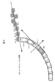
- FIG. 14 shows an example of a scene where the driving support function for collision avoidance at an intersection becomes unnecessary.
- An unnecessary operation is when a pedestrian approaches the driver while the vehicle is moving through an intersection. If we assume that the distribution of variations in the future path of the vehicle due to driver operations is the trajectory error distribution, and the variation in pedestrian speed due to sensor errors is the pedestrian error distribution, then in the case of a parallel walker, the trajectory error distribution and the pedestrian error It can be seen that there are few areas where the distributions overlap, that is, areas where there is a possibility of collision, and that unnecessary operations are likely to occur when a collision is determined.
- a vehicle control device that controls a vehicle includes an external world recognition unit that recognizes external world information of the own vehicle, a vehicle information acquisition unit that acquires the state of the own vehicle, and the own vehicle that is acquired by the external world recognition unit. a collision determination unit that determines a collision between the target object and the vehicle based on information on surrounding targets and the state of the vehicle acquired by the vehicle information acquisition unit; and a collision determination unit that determines a collision.
- the vehicle is characterized by comprising: a suppression determination section; and a control intervention determination section that determines control intervention for the own vehicle based on the results of the collision determination section and the operation suppression determination section.
- a vehicle control device that supports appropriate collision avoidance between vehicles and pedestrians, for example, at intersections where there is no environment to separate vehicles and pedestrians, such as a sidewalk or crosswalk. can.
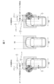
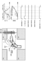
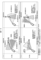
- FIG. 3 is a conceptual diagram and a time chart of the parallel progresser determination by the parallel progresser determination unit of the first embodiment (an erroneous determination scene when performed based only on the overlap rate).
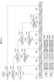
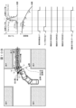
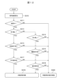
- FIG. 5 is a flowchart of a parallel progressor determination unit according to the first embodiment. 5 is a flowchart of a parallel progresser status set by a parallel progressor determination unit according to the first embodiment. 3 is a conceptual diagram and a time chart of pedestrian crossing determination by the pedestrian crossing determination unit of Example 1.
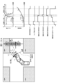
- FIG. FIG. 2 is a conceptual diagram and a time chart of pedestrian crossing determination by the pedestrian crossing determination unit of Example 1 (misjudgment scene when performed only based on overlap rate).
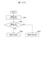
- FIG. 5 is a flowchart of a pedestrian crossing determination unit according to the first embodiment.
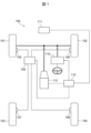
- Reference numeral 111 is an external world recognition sensor (external world recognition unit) that detects (recognizes) targets such as pedestrians existing in the outside world (surroundings) of the vehicle 100 using a camera, radar, or the like.
- Reference numeral 112 is an external world recognition controller that calculates the position and speed of a target detected (recognized) by the external world recognition sensor 111. Furthermore, the external world recognition controller 112 is a vehicle control controller capable of determining a collision between the own vehicle 100 and the target object based on the position and speed information of the target object and the vehicle information of the own vehicle 100, and determining the operation of the braking device. 200 (FIG. 2) is also provided.
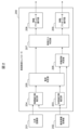
- the own vehicle traveling path estimation unit 203 estimates the future traveling path of the own vehicle from the speed, steering angle, and yaw rate of the own vehicle obtained from the vehicle information acquisition unit 202 when the own vehicle advances through an intersection.
- the collision determination unit 205 determines the overlap between the own vehicle and the target object based on the estimation results of the future course of the target object by the target object course estimation unit 204 and the future course estimation results of the own vehicle by the own vehicle course estimation unit 203.
- a collision between the target object and the own vehicle is determined by calculating the degree of overlap (overlap rate), time to collision (TTC), etc.
- the activation suppression determination unit 206 determines whether the collision requires control (actuation suppression or not, or whether activation suppression is required). . In other words, the activation suppression determining unit 206 changes the result of the collision determination and determines whether to suppress activation (unnecessary activation). If activation suppression is necessary, the activation suppression determination unit 206 transmits the activation suppression determination and the activation suppression gain to the control intervention determination unit 207.
- the control intervention determination unit 207 uses the overlap rate (hereinafter sometimes simply referred to as lap rate) calculated by the collision determination unit 205, the TTC, and the activation suppression judgment and activation suppression gain transmitted from the activation suppression determination unit 206. Based on this, it is determined whether control intervention is required. When control intervention is determined, the control intervention determination section 207 transmits an alarm and a braking command to each actuator operation section (208, 209).
- lap rate the overlap rate
- the brake actuator operation unit 209 is installed in a brake actuator such as a stability control device, and is used when the control intervention determination unit 207 determines that the risk of a collision cannot be avoided even with control intervention by warning, and control intervention by braking is necessary. Then, a braking force is applied to the vehicle 100 in accordance with the collision avoidance brake activation request and the requested deceleration transmitted by the control intervention determination unit 207.
- the additional turning determination section 212 and the turning back determining section 213 determine whether or not to increase the turning according to the turning direction based on the steering angular velocity calculation result of the steering angular velocity calculation section 210 and the turning direction judgment result of the turning direction determining section 211.
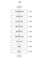
- FIG. 4 shows a flowchart of the vehicle controller 200 according to the first embodiment of the present invention.
- the own vehicle traveling path estimating unit 203 estimates the traveling path of the own vehicle from the own vehicle speed, yaw rate, and steering angle (step S303).
- the vehicle travel path refers to the trajectory that the vehicle passes, and is expressed as a set consisting of the vehicle position and direction. Predicting the course of travel is equivalent to predicting the future position and direction of the vehicle, but since it is impossible to predict accurately including the driver's intentions, in this example, the current steering angle of the vehicle is The route is predicted under the precondition that the vehicle maintains its current speed (that is, turns in a steady circle). Assuming that the vehicle behaves in a steady circular turn, the vehicle's course can be determined by knowing the vehicle's speed and yaw rate.
- the target traveling path estimating unit 204 estimates the traveling path of the target from the external world recognition information (target information) (step S304).
- the future movement of the target object is assumed to be a uniform linear movement from the current position at the current ground speed.
- the target's current motion information position and ground speed.
- the current position of the target the current target position (xR p_cur , yR p_cur ) [m] obtained from the external world recognition unit 201 is used.
- the current velocity information (VxR p_cur , VyR p_cur ) [m/s] of the target object velocity information transmitted by the external world recognition unit 201 such as a camera is used.
- the collision determination unit 205 determines whether or not the own vehicle will collide with the target object in the future based on the estimated future traveling path of the own vehicle and the future traveling path of the target object (step S305).
- the future movement of the own vehicle is determined by a steady circular turn, and the future movement of the target object is A collision simulation is performed that assumes fast linear motion and calculates the collision state at each future time from the positional relationship between the two.
- Collision simulation is a loop calculation for predicting future collisions between the own vehicle and a target object ( Figure 5).
- ⁇ Step 1 Calculate future vehicle position ⁇ (Calculate the yaw angle of your vehicle)
- the yaw angle ⁇ (t f ) [rad] of the center of gravity of the vehicle (assuming the current direction of travel of the vehicle is 0 degrees) is calculated from the current yaw rate ⁇ SA0 [rad/s] of the vehicle's current path.
- the upper and lower limits of the yaw angle of the vehicle's center of gravity are set to ⁇ 90 degrees.
- ⁇ Step 3 Determine whether there will be a future collision ⁇ Based on the target position (xsR p (t f ), ysR p (t f )) [m] calculated in step 2, if there is a positional relationship where the two overlap, it is determined that there is a "collision", and if not, it is determined that there is a "collision”. is judged as “no collision”.
- the target will have a pedestrian area with the target position as the center and the diameter of the target width, and the own vehicle will have a collision detection area with a margin in the front, back, left and right directions from the center of gravity of the own vehicle (see Figure 6). ), it is possible to easily tune the effects of sensor variations and the sensitivity of collision detection.
- Step 3-1 Front-back direction superimposition determination ⁇ If the following judgment formula is satisfied, it is determined that there is "superimposition,” otherwise, it is determined that there is no superimposition. [Number 1]
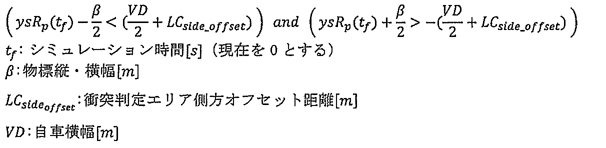
- Step 3-2 Horizontal direction superimposition determination ⁇ If the following judgment formula is satisfied, it is determined that there is "superimposition,” otherwise, it is determined that there is no superimposition. [Number 2]
- Overlap is a parameter that represents the rate at which the own vehicle and the target overlap when viewed in the lateral direction, based on the future positional relationship between the own vehicle and the target in the future up to a predetermined time when the simulation time is maximum. Calculate the rate.
- the overlap rate for each simulation time is calculated using separate formulas for cases where the target center is in front of the center of the own vehicle, or when the target center is on the left or right side, with the center of the own vehicle as the reference. (see Figure 7).
- each time overlap rate [%] is calculated based on the target position and each width value.
- ⁇ Calculation of relative velocity at the time of collision> When t fr [s] is the simulation time at which the overlap rate of each simulation time is the largest in the future up to a predetermined time period in which the simulation time is maximum, the value of the simulation time seen from the own vehicle at t fr [s] is The relative velocity of the target is calculated as the relative velocity at the time of collision. The relative speed is calculated based on the positional relationship between the host vehicle and the target object for each simulation time, the relative speed is adjusted up to the maximum simulation time, and the relative speed at the time of collision is calculated. In arbitration, the relative speed at the simulation time when the overlap rate of each simulation time is the largest is determined as the relative speed at the time of collision.
- TTC Time to collision
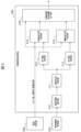
- the operation suppression determination unit 206 determines whether or not the collision really requires a warning or brake operation, and whether or not it is necessary to suppress the warning or brake operation. It is determined whether or not (step S306). In other words, the activation suppression determination section 206 determines whether or not the result of the collision determination by the collision determination section 205 needs to be changed.
- the operation suppression determination unit 206 in this embodiment calculates the steering angle speed from the steering angle information obtained from the vehicle information acquisition unit 202 (steering angle speed calculation unit 210), and calculates the steering angle and yaw rate information obtained from the vehicle information acquisition unit 202.
- the turning direction is determined from (turning direction determining section 211), and further turning or turning back is determined according to the turning direction (more turning determining section 212, turning back determining section 213).
- a parallel pedestrian is determined to require activation suppression based on the lap rate and collision determination position (anticipated collision lateral position) obtained from the collision determining section 205 (parallel pedestrian determining section 214), and when determining whether to cut back Based on the lap rate and collision determination position (expected collision lateral position) obtained from the collision determination unit 205, a pedestrian crossing judgment that requires activation suppression is performed (crossing pedestrian determination unit 215).
- the activation suppression determination method will be described in detail below.
- the control intervention determination unit 207 requests activation of warning/brake control in accordance with the collision risk calculated from the collision simulation results with each target object calculated by the collision determination unit 205 (step S307).
- control intervention is performed in the order of warning buzzer and collision avoidance brake.
- the collision risk is evaluated based on the time to collision (TTC) calculated by the collision determination unit 205.
- TTC-equivalent road distance the road distance to the collision converted from TTC
- TTC-equivalent road distance is the operating distance threshold for each control.
- An operation request is issued when the value is smaller than .
- the TTC conversion road distance is calculated by "TTC x own vehicle speed”.
- An activation request to the alarm actuator is determined when the TTC equivalent road distance is less than the control intervention threshold for the alarm buzzer.
- the control intervention determination section 207 transmits an alarm buzzer sounding command to the alarm actuator operating section 208 .
- the control intervention threshold for the warning buzzer is determined by setting the standard TTC for the warning buzzer for each vehicle speed using a map, and then multiplying the standard TTC for each vehicle speed by the own vehicle speed to obtain the standard road distance threshold.
- This control intervention threshold for the warning buzzer is determined as the final control intervention threshold for the warning buzzer by multiplying the reference road distance threshold by the adjustment gain based on the overlap rate for the warning buzzer and the activation suppression gain calculated in step S306.
- An operation request to the brake actuator is determined when the TTC equivalent road distance is less than the collision avoidance brake control intervention threshold.
- the control intervention determining unit 207 transmits a braking execution command and a predetermined deceleration request value to the brake actuator operating unit 209.
- the control intervention threshold for collision avoidance braking is determined by setting the standard TTC for collision avoidance braking for each vehicle speed by looking up a map, and multiplying the standard TTC for each vehicle speed by the own vehicle speed to obtain the standard road distance threshold.
- This control intervention threshold for collision avoidance brakes is determined by multiplying the reference road distance threshold by the adjustment gain based on the overlap rate for collision avoidance brakes and the operation suppression gain calculated in step S306, thereby obtaining the final control intervention threshold for collision avoidance brakes. shall be.
- the alarm actuator operation unit 208 which is configured with a buzzer installed in a combination meter or a single buzzer, responds to the alarm buzzer activation request transmitted from the control intervention determination unit 207. and sounds an alarm buzzer (step S308).
- the brake actuator operating unit 209 is mounted in a brake actuator such as a stability control device, and a control intervention determination unit is installed. A braking force is applied to the vehicle 100 in accordance with the collision avoidance brake activation request and the required deceleration (predetermined deceleration request value) transmitted by the controller 207 (step S309).
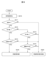
- FIG. 8 shows a flowchart of the operation suppression determination unit 206 in step S306.
- the steering angular speed calculation section 210 calculates the current steering angular speed (right steering speed or left steering speed) by time-differentiating the steering angle information obtained from the vehicle information acquisition section 202 (step S310).
- the turning direction determining unit 211 determines which direction the own vehicle is currently turning from the steering angle information and yaw rate information obtained from the vehicle information acquiring unit 202 (step S311).
- An example of a turning judgment method is to have turning judgment thresholds for each rudder angle and yaw rate, and if the current rudder angle and yaw rate both exceed the right turn judgment threshold, the right turn and left turn judgment thresholds are exceeded. It was determined that the vehicle was turning left. If either or both of the steering angle and yaw rate does not exceed the left/right turning determination threshold, it is determined that the vehicle is not turning, that is, traveling straight, and no operation suppression determination is made (step S320).
- step S311 determines whether to increase the turning if the steering angular velocity obtained in step S310 is output in the right steering direction by a predetermined value or more.
- the additional steering determination unit 212 performs an additional steering determination. (Step S312).
- the steering-back determination unit 213 makes a steering-back determination when it is determined in step S311 that the own vehicle is turning to the right, and when the steering angular velocity determined in step S310 is output in the left steering direction by a predetermined value or more. In addition, when it is determined in step S311 that the own vehicle is turning left, the steering-back determination unit 213 performs a steering-back determination when the steering angular velocity obtained in step S310 is outputted in the right steering direction by a predetermined value or more. (Step S313). Note that the processing order of step S312 and step S313 may be reversed.
- Step S320 If the steering speed does not meet the predetermined value and it cannot be determined whether the steering should be increased or reversed, it can be determined that the own vehicle is proceeding through the intersection in a steady circle, and there is no need to suppress the operation, so no judgment will be made to suppress the operation. (Step S320).
- the parallel driver determining unit 214 determines that the vehicle is turning right or turning left, there is a low possibility that the target will collide with the vehicle (therefore, it is subject to activation suppression). A determination is made as to whether or not the person is a parallel progressor (step S314 in FIG. 8).
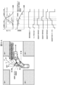
- FIG. 9A shows a conceptual diagram and a time chart of the judgment of parallel progressors. Whether or not a target object (pedestrian) with which your vehicle may collide as you proceed through an intersection is moving in parallel with your vehicle at the exit of the intersection is determined by This is determined based on the tendency (pattern) of the overlap rate (occurring to the left and right of the own vehicle) and the tendency (pattern) of the lateral velocity of the target as seen from the own vehicle. Let us take as an example the judgment of a parallel pedestrian during a right turn. It is assumed that the vehicle turns right at the intersection, and the target (pedestrian) moves from point a to point b at the intersection in a uniform straight line motion.
- the collision judgment between the own vehicle and the target object is first started when the overlap rate with the own vehicle is around 0 on the right side. From there, the overlap rate on the right reaches its peak and shifts to the overlap rate on the left. After transitioning to the overlap rate on the left side, the overlap rate shows a decreasing trend (downward trend), and eventually becomes close to 0, and eventually no collision is determined. At this time, if the parallel pedestrian is judged based only on the overlap rate, it will not be possible to distinguish the parallel pedestrian from the forward crossing pedestrian who passes through the intersection while proceeding from point c to point d in FIG. 9B.
- the lateral speed of the target (pedestrian) as seen from the vehicle is also observed at the same time. Since the vehicle is turning while proceeding through an intersection, the coordinate axes of the vehicle are changing moment by moment as the vehicle turns. Therefore, even if the target is performing uniform linear motion from point a to point b, the lateral speed of the target as seen from the own vehicle decreases from the early stage to the late stage of the turn (FIG. 9A). By observing this characteristic at the same time as the occurrence trend (pattern) of the overlap rate, it can be determined that the person is a parallel progressor. The lateral speed of the pedestrian crossing the street in FIG. 9B increases as the vehicle turns, so it can be distinguished from the pedestrian crossing in parallel in FIG. 9A. Note that the same applies to the judgment of a parallel driver during an additional left turn (see also FIG. 9D).
- FIG. 9C shows a flowchart for determining whether a person is a parallel pacer.
- the parallel walking person determination in order to determine that the target is a parallel walking person, there are four levels of parallel walking status depending on the judgment state of the target (step S401). When this parallel progressor status is 4 (step S402), it is determined that the person is a parallel progressor (step S403), and at other times (step S402), it is determined that the person is not a parallel progressor (step S404).
- FIG. 9D shows a flowchart of the Intermediate Progressor Status Set.
- the result of the collision determination unit 205 indicates that there is a collision (step S411). If there is no collision, any value of the parallel progressor status is reset to 0 (step S427). If there is a collision, it is determined whether the current parallel progressor status is 0 (step S412). If the status is not 0, the process moves on to determining whether the parallel progressor status is 1 (step S414). If the status is 0, it is determined whether the overlap rate PreOverLap (t f ) with the target is around 0 (step S413). (PreOverLap(t f ) ⁇ predetermined value) If the overlap rate is around 0, set the parallel progressor status to 1 (step S419), and if the overlap rate is not around 0, the parallel progressor status remains 0. (Step S420).
- step S414 it is determined whether the current concurrent pedestrian status is 1 (step S414). If the current concurrent progressor status is not 1, the process moves to determining whether the current concurrent progressor status is 2 (step S416). If the current parallel progressor status is 1, it is determined whether the parallel progressor determination 1 is satisfied (step S415).
- Parallel pedestrian determination 1 means that if the vehicle is turning to the right, the overlap rate with the target object is calculated on the right side, the vehicle is in an upward trend, and the lateral speed is in a downward trend ( Figure 9A). Satisfies Parallel Progressor Judgment 1. At this time, the increasing tendency of the overlap rate is determined by the fact that the change in the overlap rate per unit of time is on the + side.
- a downward trend in the lateral speed is determined based on whether the change in the absolute value of the lateral speed per unit of time is on the negative side. If the parallel progressor determination 1 is satisfied, the parallel progressor status is set to 2 (step S421). If the parallel progressor determination 1 is not satisfied, the parallel progressor status remains 1 (step S422).
- step S416 it is determined whether the current parallel walker status is 2 (step S416). If the current parallel progressor status is not 2, the process moves to a determination as to whether parallel progressor determination 3 is satisfied (step S418). If the current parallel progressor status is 2, it is determined whether parallel progressor determination 2 is satisfied (step S417).
- Parallel pedestrian determination 2 is when the overlap rate changes from the right side to the left side, the overlap rate is observed to be at its peak, and the lateral speed of the target as seen from the own vehicle is decreasing. (FIG. 9A) Satisfies Judgment 2 for Parallel Progressive Person.
- peak detection of the overlap rate is determined when the overlap rate on the right side becomes a predetermined value or more, then changes to the overlap rate on the left side, and then becomes below the predetermined value. Further, a downward trend in the lateral speed is determined based on whether the change in the absolute value of the lateral speed per unit of time is on the negative side. If the parallel progressor determination 2 is satisfied, the parallel progressor status is set to 3 (step S423). If the parallel progressor determination 2 is not satisfied, the parallel progressor status remains 2 (step S424).
- step S4108 it is determined whether parallel pedestrian determination 3 is satisfied.
- Parallel pedestrian determination 3 is satisfied when the overlap rate is on the left side, a decreasing tendency is observed, and the lateral speed of the target as seen from the own vehicle is decreasing.
- the decreasing tendency of the overlap rate is determined by the fact that the change in the overlap rate per unit of time is on the negative side.
- a downward trend in the lateral speed is determined based on whether the change in the absolute value of the lateral speed per unit of time is on the negative side. If the parallel progressor determination 3 is satisfied, the parallel progressor status is set to 4 (step S425). If the parallel progressor determination 3 is not satisfied, the parallel progressor status remains 3 (step S426).
- the pedestrian crossing determination unit 215 determines that the own vehicle is turning right or turning left, there is a low possibility that the target will hit the own vehicle (therefore, it is subject to activation suppression). It is determined whether the pedestrian is a pedestrian crossing the street (step S315 in FIG. 8).
- FIG. 10A shows a conceptual diagram and a time chart of pedestrian crossing determination. Whether or not a target (pedestrian) with which your vehicle may collide as you proceed through an intersection is crossing your vehicle at the exit of the intersection is determined by This is determined based on the tendency (pattern) of the overlap rate (occurring to the left and right of the own vehicle) and the tendency (pattern) of the lateral velocity of the target as seen from the own vehicle. Let us take as an example the judgment of a pedestrian crossing the road during a right turn. It is assumed that the own vehicle turns right at the intersection, and the target (pedestrian) advances from point e to point f at the intersection in a uniform straight line motion.
- the collision judgment between the own vehicle and the target object begins when the overlap rate with the own vehicle is around 0 on the left side. From there, the overlap rate on the left reaches its peak and shifts to the overlap rate on the right. After transitioning to the overlap rate on the right side, the overlap rate shows a decreasing trend (downward trend), and eventually becomes close to 0, and eventually no collision is determined. At this time, if pedestrians are judged to be crossing the street based only on the overlap rate, they cannot be distinguished from the pedestrians passing through the intersection in parallel while proceeding from point g to point h in FIG. 10B.
- the lateral speed of the target (pedestrian) as seen from the vehicle is also observed at the same time. Since the vehicle is turning while proceeding through an intersection, the coordinate axes of the vehicle are changing moment by moment as the vehicle turns. Therefore, even if the target is performing uniform linear motion from point e to point f, the lateral speed of the target as seen from the own vehicle increases from the early stage to the late stage of the turn (FIG. 10A). By observing this characteristic at the same time as the occurrence trend (pattern) of the overlap rate, it is possible to determine whether a pedestrian is crossing the street. Since the lateral speed of the parallel pedestrian in FIG. 10B decreases as the own vehicle turns, it can be distinguished from the cross pedestrian in FIG. 10A. Note that the same applies to the judgment of pedestrians crossing the road during a left turn and back turn (see also FIG. 10D).
- FIG. 10C shows a flowchart of pedestrian crossing determination.
- the pedestrian crossing determination determines that the target is a pedestrian crossing, so there are four levels of pedestrian crossing status depending on the determination state of the target (step S501).
- this pedestrian crossing status is 4 (step S502), it is determined that the pedestrian is a crossing pedestrian (step S503), and at other times (step S502), it is determined that the pedestrian is not a crossing pedestrian (step S504).
- FIG. 10D shows a flowchart for setting pedestrian crossing status.
- step S511 it is determined whether the result of the collision determination unit 205 indicates that there is a collision. If there is no collision, any value of the crossing pedestrian status is reset to 0 (step S527). If there is a collision, it is determined whether the current pedestrian crossing status is 0 (step S512). If the status is not 0, the process moves to determining whether the pedestrian crossing status is 1 (step S514). If the status is 0, it is determined whether the overlap rate PreOverLap (t f ) with the target object is around 0 (step S513). (PreOverLap(t f ) ⁇ predetermined value) If the overlap rate is around 0, the crossing pedestrian status is set to 1 (step S519), and if the overlap rate is not around 0, the crossing pedestrian status remains 0. (Step S520).
- step S514 if there is a collision, it is determined whether the current pedestrian crossing status is 1 (step S514). If the current pedestrian crossing status is not 1, the process moves to determining whether the current crossing pedestrian status is 2 (step S516). If the current pedestrian crossing status is 1, it is determined whether crossing pedestrian determination 1 is satisfied (step S515).
- Crossing pedestrian judgment 1 means that if the own vehicle is turning right, the overlap rate with the target object is calculated on the left side, and the lateral speed is increasing ( Figure 10A). Crossing pedestrian judgment 1 is satisfied. At this time, the increasing tendency of the overlap rate is determined by the fact that the change in the overlap rate per unit of time is on the + side.
- the increasing tendency of the lateral speed is determined by the fact that the change in the absolute value of the lateral speed per unit of time is on the + side. If the crossing pedestrian determination 1 is satisfied, the crossing pedestrian status is set to 2 (step S521). If the pedestrian crossing determination 1 is not satisfied, the pedestrian crossing status remains 1 (step S522).
- step S536 it is determined whether the current pedestrian crossing status is 2 (step S516). If the current pedestrian crossing status is not 2, the process moves to a determination as to whether crossing pedestrian determination 3 is satisfied (step S518). If the current pedestrian crossing status is 2, it is determined whether crossing pedestrian determination 2 is satisfied (step S517).
- Pedestrian crossing determination 2 is when the overlap rate changes from the left side to the right side, the overlap rate is observed to be at its peak, and the lateral speed of the target as seen from the own vehicle tends to increase. (FIG. 10A) Crossing pedestrian determination 2 is satisfied.
- peak detection of the overlap rate is determined when the overlap rate on the left side exceeds a predetermined value, then changes to the overlap rate on the right side, and then becomes below the predetermined value. Further, the increasing tendency of the lateral speed is determined by the fact that the change in the absolute value of the lateral speed per unit of time is on the + side. If the pedestrian crossing determination 2 is satisfied, the pedestrian crossing status is set to 3 (step S523). If the pedestrian crossing determination 2 is not satisfied, the pedestrian crossing status remains 2 (step S524).
- step S528 it is determined whether crossing pedestrian determination 3 is satisfied.
- Pedestrian crossing determination 3 is satisfied when the overlap rate is on the right side and a decreasing tendency is observed, and the lateral speed of the target as seen from the own vehicle is increasing.
- the decreasing tendency of the overlap rate is determined by the fact that the change in the overlap rate per unit of time is on the negative side.
- the increasing tendency of the lateral speed is determined by the fact that the change in the absolute value of the lateral speed per unit of time is on the + side. If the pedestrian crossing determination 3 is satisfied, the pedestrian crossing status is set to 4 (step S525). If the pedestrian crossing determination 3 is not satisfied, the pedestrian crossing status remains 3 (step S526).
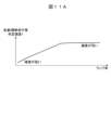
- the operation suppression determination unit 206 observes the judgment of parallel pedestrians during the additional turning operation, the judgment of pedestrians crossing when turning back, and the overlap rate between the own vehicle and the pedestrian. Regarding the parallel pedestrian judgment and the cross pedestrian judgment, the actuation suppression judgment unit 206 evaluates the accuracy of the judgment. The accuracy of the parallel pedestrian judgment and the cross pedestrian judgment is evaluated based on the current overlap rate and the rate of change in the overlap rate (see also FIGS. 9A and 10A). When the current overlap rate is high, the probability of being a parallel pedestrian at the time of cutting back or a pedestrian crossing at the time of backtracking is low (that is, the probability of malfunction is low), so the accuracy becomes low.
- the accuracy of pedestrians crossing the road when cutting back and crossing pedestrians when cutting back increases.
- This accuracy is set by drawing a map as shown in FIG. 11A, and the translation/crossing pedestrian determination accuracy is set to 1.
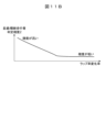
- the rate of change in the overlap rate the higher the rate of change, the higher the possibility of a collision, and therefore the lower the possibility (certainty) of being a translating/crossing pedestrian.
- the rate of change the lower the possibility of a collision, and therefore the higher the possibility (accuracy) of being a translating/crossing pedestrian.
- the translation/crossing pedestrian determination accuracy based on the rate of change in the overlap rate is set by drawing a map as shown in FIG. 11B, and is set to 2 for the translation/crossing pedestrian determination accuracy.
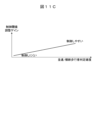
- These translation/crossing pedestrian determination accuracy 1 and translation/crossing pedestrian determination accuracy 2 are used as the final translation/crossing pedestrian determination accuracy.
- the final translation/crossing pedestrian determination accuracy may be calculated by multiplying accuracy 1 and accuracy 2, or may be calculated by selecting high or selecting low for both. Then, a control threshold adjustment gain as shown in FIG. 11C is set according to this translation/crossing pedestrian determination accuracy.
- the actuation suppression judgment result output unit 216 outputs the above-mentioned “parallel pedestrian judgment when turning further”, “crossing pedestrian judgment when cutting back”, and “control threshold value” to the control intervention judgment unit 207. "adjustment gain" (step S316 in FIG. 8).
- the control intervention determination unit 207 adjusts the control intervention threshold, which is the criterion for determining the control intervention described above, based on the sent control threshold adjustment gain.
- the vehicle controller (vehicle control device) 200 of the present embodiment includes an external world recognition unit 201 that recognizes external world information of the own vehicle represented by a camera, a radar, etc., and the state of the own vehicle ( A vehicle information acquisition unit 202 that acquires vehicle speed, steering angle, yaw rate, etc.) and information on targets (pedestrians, etc.) around the vehicle acquired by the external world recognition unit 201 and information acquired by the vehicle information acquisition unit 202.
- an external world recognition unit 201 that recognizes external world information of the own vehicle represented by a camera, a radar, etc.
- the state of the own vehicle A vehicle information acquisition unit 202 that acquires vehicle speed, steering angle, yaw rate, etc.) and information on targets (pedestrians, etc.) around the vehicle acquired by the external world recognition unit 201 and information acquired by the vehicle information acquisition unit 202.
- a collision determination unit 205 that determines a collision between the target object and the own vehicle based on the state of the own vehicle; and when a collision is determined by the collision determination unit 205, a lap between the target object and the own vehicle; Whether or not to change the result of the collision determination (whether to suppress unnecessary operations) based on the change in rate (time change) and the change (time change) in the lateral speed relative to the own vehicle that occurs at the target object (time change) and a control intervention determination unit 207 that determines control intervention for the own vehicle (with respect to the target object) based on the results of the collision determination unit 205 and the activation restraint determination unit 206. Be prepared.
- the actuation suppression determination unit 206 determines the turning direction of the own vehicle, and determines (( 9A/FIG. 10A) It is determined that the target object is a parallel pedestrian/crossing pedestrian whose operation is to be suppressed.
- Example 2 Next, Example 2 will be explained. Since the basic configuration of the second embodiment is the same as that of the first embodiment, the differences from the first embodiment will be explained.
- the activation suppression judgment is made based on the judgment of a parallel pedestrian at the time of adding a turn and the judgment of a crossing pedestrian at the time of turning back, but in the second embodiment, in addition to this, the collision determination unit 205
- the degree of parallelism/perpendicularity between the own vehicle and the target object is determined from the relative speed of the target object at the time of collision determination calculated in step 1, and if these conditions are met, a determination is made to suppress the operation.
- the speed vector of the pedestrian at the time of the collision is evaluated compared to the first embodiment, it is possible to further limit the targets for which the operation is suppressed.
- FIG. 12 shows a flowchart of the operation suppression determination unit 206 of the second embodiment. Since steps S310 to S316 and S320 are the same as in the first embodiment, the parallelism determination in step S317 and the orthogonality determination in step S318 will be explained.
- ⁇ p tan ⁇ 1 (Vyp /Vxp)
- Kp is a predetermined arctangent value
- the operation suppression determination unit 206 removes the parallel pedestrian/crossing pedestrian who is the object of the operation suppression from the own vehicle. It is defined based on the speed vector of the pedestrian seen.
- the operation suppression target is It can be further limited.
- the present invention is not limited to the above-described embodiments, and includes various modifications. Further, for example, the configurations of the embodiments described above are explained in detail in order to explain the present invention in an easy-to-understand manner, and the present invention is not necessarily limited to having all the configurations described. Further, a part of the configuration of each embodiment can be added to, deleted from, or replaced with other configurations.
- each of the above-mentioned configurations, functions, processing units, processing means, etc. may be partially or entirely realized by hardware, for example, by designing an integrated circuit.
- the present invention can also be realized by software program codes that realize the functions of the embodiments.
- a storage medium on which a program code is recorded is provided to a computer, and a processor included in the computer reads the program code stored on the storage medium.
- the program code itself read from the storage medium realizes the functions of the embodiments described above, and the program code itself and the storage medium storing it constitute the present invention.
- Examples of storage media for supplying such program codes include flexible disks, CD-ROMs, DVD-ROMs, hard disks, SSDs (Solid State Drives), optical disks, magneto-optical disks, CD-Rs, magnetic tapes, A non-volatile memory card, ROM, etc. are used.
- the software program code that realizes the functions of the embodiment can be stored in a storage means such as a computer's hard disk or memory, or a storage medium such as a CD-RW or CD-R.
- a processor included in the computer may read and execute the program code stored in the storage means or the storage medium.
- control lines and information lines are those considered necessary for explanation, and not all control lines and information lines are necessarily shown in the product. All configurations may be interconnected.
Landscapes
- Engineering & Computer Science (AREA)
- Mechanical Engineering (AREA)
- Automation & Control Theory (AREA)
- Transportation (AREA)
- Physics & Mathematics (AREA)
- Mathematical Physics (AREA)
- General Physics & Mathematics (AREA)
- Computer Vision & Pattern Recognition (AREA)
- Traffic Control Systems (AREA)
- Control Of Driving Devices And Active Controlling Of Vehicle (AREA)
Abstract
Description
(1)交差点AEB(衝突被害軽減ブレーキ)は、旋回する自車の進行路と物標の進行路から衝突判断を行うが、自車進行路の推定誤差により並進歩行者等に対して不要作動が発生しやすい。
(2)誤作動を避けるために歩道や横断歩道などの車両と歩行者を分離する情報を用いて不要作動防止を行う手法が一般的である。
(3)国内や海外では歩道や横断歩道がない交差点が多く存在し、このような交差点では従来の手法では不要作動を防止できない。
図1に、本発明が対象とする実施例1の運転支援システムを搭載する車両の概略構成図を示す。車両(自車)100は4輪車両であり、符号101は左前輪、符号102は右前輪、符号103は左後輪、符号104は右後輪である。符号105は左前輪101に具備されたホイルシリンダ、符号106は右前輪102に具備されたホイルシリンダ、符号107は左後輪103に具備されたホイルシリンダ、符号108は右後輪104に具備されたホイルシリンダである。
衝突シミュレーションは、シミュレーション時間毎に自車と物標の位置関係に基づいて衝突判定を行い、最大シミュレーション時間までの衝突判定結果を調停し、最終的な衝突判定結果を算出する。以下step1~3を、シミュレーション時間tf毎に、tf=最小値からtf=最大値まで繰り返す。
(自車のヨー角を算出する)
初めに、現時点の自車進行路ヨーレートγSA0[rad/s]から自車重心のヨー角θ(tf)[rad](現在の自車進行方向を0度とする)を算出する。ただし、交差点の走行を想定しているため、自車重心のヨー角は±90度を上下限値とする。
次に、自車重心のヨー角θ(tf)[rad]、現在の自車速V0[m/s]に基づいて、将来の自車重心位置(xsRv(tf),ysRv(tf))[m]を算出する。なお、θ(t)が±π/2を超える範囲では直進走行を示す。
(将来の物標位置(現在の車両座標)を算出する)
初めに、現在の物標対地速度(VxRp_cur,VyRp_cur)[m/s]と物標座標(xRp_cur,yRp_cur)[m]から、現在の車両座標における将来の物標位置(xsRp(tf),ysRp(tf))[m]を算出する。
step2で算出した物標位置(xsRp(tf),ysRp(tf))[m]に基づいて両者が重畳する位置関係にある場合には“衝突あり”判定とし、そうでない場合には“衝突なし”判定とする。ただし、物標には物標位置を中心として物標幅を直径とした歩行者エリア、自車には自車重心から前後左右方向にマージンを持たせた衝突判定エリアを設ける(図6を参照)ことで、センサばらつきによる影響や衝突判定の感度を簡単にチューニングできるようにする。
以下の判定式を満足した場合に“重畳あり”、そうでない場合に“重畳なし”とする。
[数1]

以下の判定式を満足した場合に“重畳あり”、そうでない場合に“重畳なし”とする。
[数2]
シミュレーション時間が最大となる所定時間先までの将来において、自車と物標の将来の位置関係に基づいて、横方向で見たときに自車と物標が重なる割合を表すパラメータであるオーバーラップ率を算出する。各シミュレーション時間のオーバーラップ率は、自車中心を基準として、自車中心正面に物標中心がある場合か、左側あるいは右側に物標中心がある場合かの各々に対して別々の算出式で算出する(図7を参照)。
自車の左側に物標中心がある場合(図7左側)は、物標位置と各幅値を基に各時間オーバーラップ率[%]を算出する。
[数3]
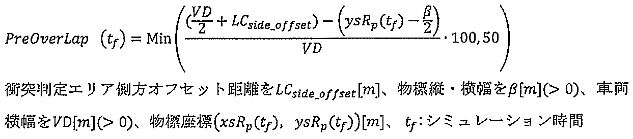
自車の右側に物標中心がある場合(図7右側)は、物標位置と各幅値を基に各時間オーバーラップ率[%]を算出する。
[数4]

シミュレーション時間が最大となる所定時間先までの将来において、各シミュレーション時間のオーバーラップ率が最も大きくなったシミュレーション時間をtfr[s]としたときに、tfr[s]における自車から見た物標の相対速度を衝突時の相対速度として算出する。シミュレーション時間毎に自車と物標の位置関係に基づいて相対速度を算出し、最大シミュレーション時間までの相対速度を調停し、衝突時の相対速度を算出する。調停では、各シミュレーション時間のオーバーラップ率が最も大きくなったシミュレーション時間における相対速度を衝突時の相対速度とする。
自車重心のヨー角θ(tfr)、現在の物標対地速度(VxRp_cur,VyRp_cur)に基づいて、X方向、及び、Y方向の物標相対速度を以下の式にて算出する。このとき、自車の横滑り角を0[rad]として近似することで、Y方向(横方向)の自車速度を0[m/s]、X方向(縦方向)の自車速をV0[m/s](現在の自車速)として取り扱う。
[数5]
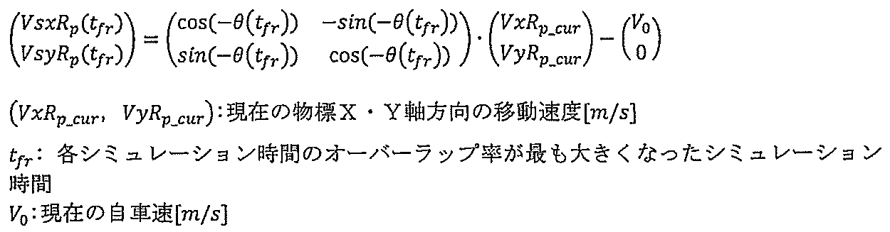
シミュレーション時間が最大となる所定時間先までの将来において、衝突までの余裕時間を算出する。衝突までの余裕時間(TTC)は、初めて“衝突あり”判定となったシミュレーション時間tfc[s]を衝突までの時間とする。
次に実施例2について説明する。実施例2の基本的な構成は実施例1と同じであるため、実施例1と異なる点について説明する。実施例1では切り増し時の並進歩行者判断と切り戻し時の横断歩行者判断にて作動抑制判断を行っているが、実施例2ではこれに加えて、並進歩行者判定時に衝突判定部205で演算された衝突判定時の物標の相対速度から自車と物標の平行度/直交度を判断し、これらの条件に合致した場合に作動抑制判断を行う。実施例2においては、実施例1に対して衝突時の歩行者の速度ベクトルを評価するため、作動抑制となる対象をさらに限定することができる。
101 左前輪
102 右前輪
103 左後輪
104 右後輪
105、106、107、108 ホイルシリンダ
109 ホイルシリンダ液圧制御装置
110 ステアリング装置
111 外界認識センサ
112 外界認識コントローラ
113 エンジン
200 車両制御コントローラ(車両制御装置)
201 外界認識部
202 車両情報取得部
203 自車進行路推定部
204 物標進行路推定部
205 衝突判定部
206 作動抑制判定部
207 制御介入判定部
208 警報アクチュエータ操作部
209 制動アクチュエータ操作部
210 舵角速度算出部
211 旋回方向判定部
212 切り増し判定部
213 切り戻し判定部
214 並進歩行者判定部
215 横断歩行者判定部
216 作動抑制判定結果出力部
Claims (15)
- 自車の外界情報を認識する外界認識部と、
前記自車の状態を取得する車両情報取得部と、
前記外界認識部により取得した前記自車周辺の物標の情報と前記車両情報取得部により取得した前記自車の状態とに基づき、前記物標と前記自車の衝突を判定する衝突判定部と、
前記衝突判定部により衝突判定となった場合、前記物標と前記自車とのラップ率の変化と前記物標に発生する前記自車に対する横速度の変化とに基づき、前記衝突判定の結果を変更するか否かを判定する作動抑制判定部と、
前記衝突判定部と前記作動抑制判定部の結果より、前記自車への制御介入を判定する制御介入判定部と、を備えることを特徴とする車両制御装置。 - 請求項1に記載の車両制御装置であって、
前記作動抑制判定部は、前記自車の旋回方向を判定し、前記自車の旋回方向に対して前記自車の左右に発生する前記ラップ率の発生パターンと前記横速度の発生パターンから前記物標が作動抑制対象である並進歩行者であることを判定することを特徴とする車両制御装置。 - 請求項1に記載の車両制御装置であって、
前記作動抑制判定部は、前記自車の旋回方向を判定し、前記自車の旋回方向に対して前記自車の左右に発生する前記ラップ率の発生パターンと前記横速度の発生パターンから前記物標が作動抑制対象である横断歩行者であることを判定することを特徴とする車両制御装置。 - 請求項2に記載の車両制御装置であって、
前記作動抑制判定部は、前記自車の旋回中の切り増しを判定し、前記自車の旋回方向に対して前記自車の左右に発生する前記ラップ率の発生パターンと前記横速度の発生パターンから前記物標が作動抑制対象である並進歩行者であることを判定することを特徴とする車両制御装置。 - 請求項2に記載の車両制御装置であって、
前記作動抑制判定部は、前記自車の旋回中の切り増しを判定し、前記自車の右旋回切り増し中に前記自車の右側から上昇して前記自車の左側で下降する前記ラップ率の発生パターンまたは前記自車の左旋回切り増し中に前記自車の左側から上昇して前記自車の右側で下降する前記ラップ率の発生パターン、且つ、前記自車の旋回中に減少する前記横速度の発生パターンから、前記物標が作動抑制対象である並進歩行者であることを判定することを特徴とする車両制御装置。 - 請求項3に記載の車両制御装置であって、
前記作動抑制判定部は、前記自車の旋回中の切り戻しを判定し、前記自車の旋回方向に対して前記自車の左右に発生する前記ラップ率の発生パターンと前記横速度の発生パターンから前記物標が作動抑制対象である横断歩行者であることを判定することを特徴とする車両制御装置。 - 請求項3に記載の車両制御装置であって、
前記作動抑制判定部は、前記自車の旋回中の切り戻しを判定し、前記自車の右旋回切り戻し中に前記自車の左側から上昇して前記自車の右側で下降する前記ラップ率の発生パターンまたは前記自車の左旋回切り戻し中に前記自車の右側から上昇して前記自車の左側で下降する前記ラップ率の発生パターン、且つ、前記自車の旋回中に増加する前記横速度の発生パターンから、前記物標が作動抑制対象である横断歩行者であることを判定することを特徴とする車両制御装置。 - 請求項2に記載の車両制御装置であって、
前記作動抑制判定部は、前記ラップ率または前記ラップ率の変化率の少なくとも一方から前記並進歩行者判定の確度を算出し、前記並進歩行者判定の確度から、前記制御介入判定部において制御介入の判定基準となる制御介入閾値を調整する制御閾値調整ゲインを設定することを特徴とする車両制御装置。 - 請求項2に記載の車両制御装置であって、
前記作動抑制判定部は、前記ラップ率が低いほど、または、前記ラップ率の変化率が小さいほど、確度が高くなるように前記並進歩行者判定の確度を算出し、前記並進歩行者判定の確度から、前記制御介入判定部において制御介入の判定基準となる制御介入閾値を調整する制御閾値調整ゲインを設定することを特徴とする車両制御装置。 - 請求項3に記載の車両制御装置であって、
前記作動抑制判定部は、前記ラップ率または前記ラップ率の変化率の少なくとも一方から前記横断歩行者判定の確度を算出し、前記横断歩行者判定の確度から、前記制御介入判定部において制御介入の判定基準となる制御介入閾値を調整する制御閾値調整ゲインを設定することを特徴とする車両制御装置。 - 請求項3に記載の車両制御装置であって、
前記作動抑制判定部は、前記ラップ率が低いほど、または、前記ラップ率の変化率が小さいほど、確度が高くなるように前記横断歩行者判定の確度を算出し、前記横断歩行者判定の確度から、前記制御介入判定部において制御介入の判定基準となる制御介入閾値を調整する制御閾値調整ゲインを設定することを特徴とする車両制御装置。 - 請求項2に記載の車両制御装置であって、
前記作動抑制判定部は、前記作動抑制対象である前記並進歩行者を前記自車から見た歩行者の速度ベクトルから規定することを特徴とする車両制御装置。 - 請求項2に記載の車両制御装置であって、
前記作動抑制判定部は、前記作動抑制対象である前記並進歩行者を前記自車から見た歩行者の速度ベクトルから判断する前記自車と前記歩行者の平行度から規定することを特徴とする車両制御装置。 - 請求項3に記載の車両制御装置であって、
前記作動抑制判定部は、前記作動抑制対象である前記横断歩行者を前記自車から見た歩行者の速度ベクトルから規定することを特徴とする車両制御装置。 - 請求項3に記載の車両制御装置であって、
前記作動抑制判定部は、前記作動抑制対象である前記横断歩行者を前記自車から見た歩行者の速度ベクトルから判断する前記自車と前記歩行者の直交度から規定することを特徴とする車両制御装置。
Priority Applications (4)
| Application Number | Priority Date | Filing Date | Title |
|---|---|---|---|
| DE112023002529.0T DE112023002529T5 (de) | 2022-07-07 | 2023-03-02 | Fahrzeugsteuervorrichtung |
| US18/880,773 US20260001535A1 (en) | 2022-07-07 | 2023-03-02 | Vehicle control device |
| CN202380048352.1A CN119403716A (zh) | 2022-07-07 | 2023-03-02 | 车辆控制装置 |
| JP2024531920A JP7829037B2 (ja) | 2022-07-07 | 2023-03-02 | 車両制御装置 |
Applications Claiming Priority (2)
| Application Number | Priority Date | Filing Date | Title |
|---|---|---|---|
| JP2022-109397 | 2022-07-07 | ||
| JP2022109397 | 2022-07-07 |
Publications (1)
| Publication Number | Publication Date |
|---|---|
| WO2024009557A1 true WO2024009557A1 (ja) | 2024-01-11 |
Family
ID=89452939
Family Applications (1)
| Application Number | Title | Priority Date | Filing Date |
|---|---|---|---|
| PCT/JP2023/007804 Ceased WO2024009557A1 (ja) | 2022-07-07 | 2023-03-02 | 車両制御装置 |
Country Status (5)
| Country | Link |
|---|---|
| US (1) | US20260001535A1 (ja) |
| JP (1) | JP7829037B2 (ja) |
| CN (1) | CN119403716A (ja) |
| DE (1) | DE112023002529T5 (ja) |
| WO (1) | WO2024009557A1 (ja) |
Families Citing this family (1)
| Publication number | Priority date | Publication date | Assignee | Title |
|---|---|---|---|---|
| KR20260028336A (ko) * | 2024-08-22 | 2026-03-04 | 현대자동차주식회사 | 객체의 횡방향 오프셋을 계산하기 위한 방법 및 장치 |
Citations (5)
| Publication number | Priority date | Publication date | Assignee | Title |
|---|---|---|---|---|
| JP2008282097A (ja) * | 2007-05-08 | 2008-11-20 | Toyota Central R&D Labs Inc | 衝突危険度推定装置及びドライバ支援装置 |
| JP2010250501A (ja) * | 2009-04-14 | 2010-11-04 | Hitachi Automotive Systems Ltd | 車両用外界認識装置及びそれを用いた車両システム |
| JP2017077829A (ja) * | 2015-10-21 | 2017-04-27 | 富士重工業株式会社 | 車両の運転支援制御装置 |
| JP2019028841A (ja) * | 2017-08-01 | 2019-02-21 | トヨタ自動車株式会社 | 車外報知装置 |
| US20220388502A1 (en) * | 2021-06-03 | 2022-12-08 | Hyundai Motor Company | Lateral movement system for collision avoidance |
Family Cites Families (5)
| Publication number | Priority date | Publication date | Assignee | Title |
|---|---|---|---|---|
| JP6493365B2 (ja) * | 2016-05-19 | 2019-04-03 | 株式会社デンソー | 車両制御装置、車両制御方法 |
| JP6828428B2 (ja) * | 2016-12-27 | 2021-02-10 | 株式会社デンソー | 車両用衝突回避支援装置および車両の衝突回避支援方法 |
| JP6973290B2 (ja) * | 2018-05-21 | 2021-11-24 | 株式会社デンソー | 走行支援装置 |
| KR102932261B1 (ko) * | 2019-06-07 | 2026-03-04 | 주식회사 에이치엘클레무브 | 차량 제어 방법, 차량 제어 장치, 이를 포함하는 차량 제어 시스템 |
| JP2026026622A (ja) * | 2024-08-05 | 2026-02-18 | トヨタ自動車株式会社 | 運転支援装置 |
-
2023
- 2023-03-02 DE DE112023002529.0T patent/DE112023002529T5/de active Pending
- 2023-03-02 JP JP2024531920A patent/JP7829037B2/ja active Active
- 2023-03-02 WO PCT/JP2023/007804 patent/WO2024009557A1/ja not_active Ceased
- 2023-03-02 US US18/880,773 patent/US20260001535A1/en active Pending
- 2023-03-02 CN CN202380048352.1A patent/CN119403716A/zh active Pending
Patent Citations (5)
| Publication number | Priority date | Publication date | Assignee | Title |
|---|---|---|---|---|
| JP2008282097A (ja) * | 2007-05-08 | 2008-11-20 | Toyota Central R&D Labs Inc | 衝突危険度推定装置及びドライバ支援装置 |
| JP2010250501A (ja) * | 2009-04-14 | 2010-11-04 | Hitachi Automotive Systems Ltd | 車両用外界認識装置及びそれを用いた車両システム |
| JP2017077829A (ja) * | 2015-10-21 | 2017-04-27 | 富士重工業株式会社 | 車両の運転支援制御装置 |
| JP2019028841A (ja) * | 2017-08-01 | 2019-02-21 | トヨタ自動車株式会社 | 車外報知装置 |
| US20220388502A1 (en) * | 2021-06-03 | 2022-12-08 | Hyundai Motor Company | Lateral movement system for collision avoidance |
Also Published As
| Publication number | Publication date |
|---|---|
| US20260001535A1 (en) | 2026-01-01 |
| JPWO2024009557A1 (ja) | 2024-01-11 |
| JP7829037B2 (ja) | 2026-03-12 |
| DE112023002529T5 (de) | 2025-05-15 |
| CN119403716A (zh) | 2025-02-07 |
Similar Documents
| Publication | Publication Date | Title |
|---|---|---|
| JP7295012B2 (ja) | 車両制御システム、および、車両制御方法 | |
| US10754347B2 (en) | Vehicle control device | |
| JP6809890B2 (ja) | 車両制御装置 | |
| RU2685108C1 (ru) | Система поддержки рулевого управления | |
| JP6525402B2 (ja) | 車両制御装置 | |
| JP6525401B2 (ja) | 車両制御装置 | |
| JP7096350B2 (ja) | 走行制御装置、車両及び走行制御方法 | |
| JP5300357B2 (ja) | 衝突防止支援装置 | |
| CN103262138B (zh) | 行驶支援装置、行驶支援方法及车辆 | |
| JP7431697B2 (ja) | 車両の走行制御装置及び車両の走行制御システム | |
| JP6273754B2 (ja) | 走行制御装置及び走行制御方法 | |
| JP2019043298A (ja) | 車両制御装置 | |
| JP6838525B2 (ja) | 車両制御装置 | |
| KR20170091144A (ko) | 목표 경로 생성 장치 및 주행 제어 장치 | |
| JP2016126360A (ja) | 車両制御システム | |
| CN101443831A (zh) | 辅助控制装置 | |
| JP2019043396A (ja) | 運転支援車両の走行制御方法及び走行制御装置 | |
| JP2019043195A (ja) | 車両制御装置 | |
| JP2019043431A (ja) | 走行制御装置、走行制御方法およびプログラム | |
| JP2019144758A (ja) | 自動運転支援装置、自動運転支援システム、自動運転支援方法及びプログラム | |
| JP7550811B2 (ja) | 車両制御装置、車両制御方法、およびプログラム | |
| JP2021006431A (ja) | 運転支援方法及び運転支援装置 | |
| US12491872B2 (en) | Vehicle collision control system | |
| JP6805767B2 (ja) | 車両制御システム | |
| JP7829037B2 (ja) | 車両制御装置 |
Legal Events
| Date | Code | Title | Description |
|---|---|---|---|
| 121 | Ep: the epo has been informed by wipo that ep was designated in this application |
Ref document number: 23835098 Country of ref document: EP Kind code of ref document: A1 |
|
| WWE | Wipo information: entry into national phase |
Ref document number: 2024531920 Country of ref document: JP |
|
| WWE | Wipo information: entry into national phase |
Ref document number: 202380048352.1 Country of ref document: CN |
|
| WWE | Wipo information: entry into national phase |
Ref document number: 18880773 Country of ref document: US |
|
| WWE | Wipo information: entry into national phase |
Ref document number: 112023002529 Country of ref document: DE |
|
| WWP | Wipo information: published in national office |
Ref document number: 202380048352.1 Country of ref document: CN |
|
| WWP | Wipo information: published in national office |
Ref document number: 112023002529 Country of ref document: DE |
|
| 122 | Ep: pct application non-entry in european phase |
Ref document number: 23835098 Country of ref document: EP Kind code of ref document: A1 |
|
| WWP | Wipo information: published in national office |
Ref document number: 18880773 Country of ref document: US |