WO2024009426A1 - 画像処理装置、制御方法、及びプログラム - Google Patents
画像処理装置、制御方法、及びプログラム Download PDFInfo
- Publication number
- WO2024009426A1 WO2024009426A1 PCT/JP2022/026813 JP2022026813W WO2024009426A1 WO 2024009426 A1 WO2024009426 A1 WO 2024009426A1 JP 2022026813 W JP2022026813 W JP 2022026813W WO 2024009426 A1 WO2024009426 A1 WO 2024009426A1
- Authority
- WO
- WIPO (PCT)
- Prior art keywords
- history
- image processing
- area
- screen
- button
- Prior art date
- Legal status (The legal status is an assumption and is not a legal conclusion. Google has not performed a legal analysis and makes no representation as to the accuracy of the status listed.)
- Ceased
Links
Images


Classifications
-
- G—PHYSICS
- G06—COMPUTING OR CALCULATING; COUNTING
- G06F—ELECTRIC DIGITAL DATA PROCESSING
- G06F3/00—Input arrangements for transferring data to be processed into a form capable of being handled by the computer; Output arrangements for transferring data from processing unit to output unit, e.g. interface arrangements
- G06F3/14—Digital output to display device ; Cooperation and interconnection of the display device with other functional units
-
- G—PHYSICS
- G06—COMPUTING OR CALCULATING; COUNTING
- G06F—ELECTRIC DIGITAL DATA PROCESSING
- G06F3/00—Input arrangements for transferring data to be processed into a form capable of being handled by the computer; Output arrangements for transferring data from processing unit to output unit, e.g. interface arrangements
- G06F3/01—Input arrangements or combined input and output arrangements for interaction between user and computer
- G06F3/048—Interaction techniques based on graphical user interfaces [GUI]
- G06F3/0481—Interaction techniques based on graphical user interfaces [GUI] based on specific properties of the displayed interaction object or a metaphor-based environment, e.g. interaction with desktop elements like windows or icons, or assisted by a cursor's changing behaviour or appearance
- G06F3/0482—Interaction with lists of selectable items, e.g. menus
-
- G—PHYSICS
- G06—COMPUTING OR CALCULATING; COUNTING
- G06F—ELECTRIC DIGITAL DATA PROCESSING
- G06F3/00—Input arrangements for transferring data to be processed into a form capable of being handled by the computer; Output arrangements for transferring data from processing unit to output unit, e.g. interface arrangements
- G06F3/01—Input arrangements or combined input and output arrangements for interaction between user and computer
- G06F3/048—Interaction techniques based on graphical user interfaces [GUI]
- G06F3/0484—Interaction techniques based on graphical user interfaces [GUI] for the control of specific functions or operations, e.g. selecting or manipulating an object, an image or a displayed text element, setting a parameter value or selecting a range
- G06F3/0485—Scrolling or panning
-
- G—PHYSICS
- G06—COMPUTING OR CALCULATING; COUNTING
- G06F—ELECTRIC DIGITAL DATA PROCESSING
- G06F3/00—Input arrangements for transferring data to be processed into a form capable of being handled by the computer; Output arrangements for transferring data from processing unit to output unit, e.g. interface arrangements
- G06F3/01—Input arrangements or combined input and output arrangements for interaction between user and computer
- G06F3/048—Interaction techniques based on graphical user interfaces [GUI]
- G06F3/0487—Interaction techniques based on graphical user interfaces [GUI] using specific features provided by the input device, e.g. functions controlled by the rotation of a mouse with dual sensing arrangements, or of the nature of the input device, e.g. tap gestures based on pressure sensed by a digitiser
- G06F3/0488—Interaction techniques based on graphical user interfaces [GUI] using specific features provided by the input device, e.g. functions controlled by the rotation of a mouse with dual sensing arrangements, or of the nature of the input device, e.g. tap gestures based on pressure sensed by a digitiser using a touch-screen or digitiser, e.g. input of commands through traced gestures
- G06F3/04883—Interaction techniques based on graphical user interfaces [GUI] using specific features provided by the input device, e.g. functions controlled by the rotation of a mouse with dual sensing arrangements, or of the nature of the input device, e.g. tap gestures based on pressure sensed by a digitiser using a touch-screen or digitiser, e.g. input of commands through traced gestures for inputting data by handwriting, e.g. gesture or text
-
- G—PHYSICS
- G06—COMPUTING OR CALCULATING; COUNTING
- G06F—ELECTRIC DIGITAL DATA PROCESSING
- G06F3/00—Input arrangements for transferring data to be processed into a form capable of being handled by the computer; Output arrangements for transferring data from processing unit to output unit, e.g. interface arrangements
- G06F3/01—Input arrangements or combined input and output arrangements for interaction between user and computer
- G06F3/048—Interaction techniques based on graphical user interfaces [GUI]
- G06F3/0487—Interaction techniques based on graphical user interfaces [GUI] using specific features provided by the input device, e.g. functions controlled by the rotation of a mouse with dual sensing arrangements, or of the nature of the input device, e.g. tap gestures based on pressure sensed by a digitiser
- G06F3/0488—Interaction techniques based on graphical user interfaces [GUI] using specific features provided by the input device, e.g. functions controlled by the rotation of a mouse with dual sensing arrangements, or of the nature of the input device, e.g. tap gestures based on pressure sensed by a digitiser using a touch-screen or digitiser, e.g. input of commands through traced gestures
- G06F3/04886—Interaction techniques based on graphical user interfaces [GUI] using specific features provided by the input device, e.g. functions controlled by the rotation of a mouse with dual sensing arrangements, or of the nature of the input device, e.g. tap gestures based on pressure sensed by a digitiser using a touch-screen or digitiser, e.g. input of commands through traced gestures by partitioning the display area of the touch-screen or the surface of the digitising tablet into independently controllable areas, e.g. virtual keyboards or menus
Definitions
- the present disclosure relates to an image processing device, a control method, and a program.
- Patent Document 1 discloses a menu area in which function buttons corresponding to the type of image processing are arranged, and history buttons corresponding to image processing completed in the past (hereinafter referred to as "completed image processing") are arranged.
- An image processing apparatus is described that has an operation panel that displays history areas side by side.
- the image processing settings corresponding to the history button are reproduced, thereby saving the user the trouble of inputting the settings. be able to.
- the image processing device as described above has room for improvement in terms of further increasing the convenience for users who use the history button.
- the present disclosure provides an image processing device, a control method, and a program that can further improve user convenience.
- An image processing device is an image processing device that executes a plurality of functions related to image processing, and includes a menu area in which function buttons corresponding to the plurality of functions are arranged, and a completed image.
- an operation panel having a display section that displays a history area in which history buttons corresponding to processes are arranged; and a first history screen in which history buttons are arranged; and in response to a user operation on the operation panel, from the first history screen, and a control unit that controls the display unit to switch to a second history screen in which the history area is expanded.
- a control method is a control method for controlling an image processing apparatus that executes a plurality of functions related to image processing, the control method comprising: a menu area in which function buttons corresponding to the plurality of functions are arranged; , a history area in which history buttons corresponding to completed image processing are arranged, and displaying on an operation panel a first history screen in which history buttons corresponding to completed image processing are arranged; and switching to a second history screen in which the history area is expanded.
- a program includes an image processing device that executes a plurality of functions related to image processing, a menu area in which function buttons corresponding to the plurality of functions are arranged, and a menu area corresponding to completed image processing. displaying on an operation panel a history area in which history buttons are arranged; and expanding the history area from the first history screen in response to a user operation on the operation panel. and switching to the second history screen.
- FIG. 1 is a diagram showing a functional block configuration of an image processing device according to an embodiment.
- 1 is a diagram illustrating an example of the external configuration of an image processing apparatus according to an embodiment.
- FIG. 3 is a diagram illustrating an example of a home screen displayed on the display section of the operation panel according to the embodiment.
- FIG. 3 is a diagram showing an example of a copy screen according to the embodiment.
- FIG. 7 is a diagram illustrating an example of a screen display when a history area (history button) is operated according to the embodiment.
- FIG. 7 is a diagram illustrating an example of a history area expansion operation according to the embodiment.
- FIG. 3 is a diagram illustrating an example of a control flow of the image processing apparatus according to the embodiment.
- FIG. 1 is a diagram illustrating an example of the external configuration of an image processing apparatus according to an embodiment.
- FIG. 3 is a diagram illustrating an example of a home screen displayed on the display section of the operation panel according to the embodiment.
- FIG. 3
- FIG. 7 is a diagram for explaining a first modification example of the history area expansion operation according to the embodiment.
- FIG. 7 is a diagram for explaining a second modification example of the history area expansion operation according to the embodiment.
- FIG. 7 is a diagram for explaining an example of a trigger for switching to a second history screen according to a second modification example.
- FIG. 7 is a diagram for explaining a third modification example of the history area expansion operation according to the embodiment.
- FIG. 7 is a diagram for explaining a fourth modification example of the history area expansion operation according to the embodiment.
- FIG. 7 is a diagram for explaining an operation of expanding a history area according to another embodiment.
- FIG. 1 is a diagram showing a functional block configuration of an image processing apparatus 1 according to an embodiment.
- FIG. 2 is a diagram showing an example of the external configuration of the image processing device 1 according to the embodiment.
- the "image” may include only characters.
- the format of the "image data” may be various, for example, it may be a vector format or a raster format. In the description of the embodiments, for convenience, "image” and “image data” may not be strictly distinguished.
- the format of the "image data” may be converted as appropriate during the process of image processing.
- the image processing device 1 includes a printer 10, a scanner 20, a communication section 30, an operation panel 40, a control section 50, and a storage section 60.
- the image processing device 1 has a configuration capable of performing one or more types of image processing.
- a printer 10, a scanner 20, and a communication section 30 are provided as components for performing image processing.
- the printer 10, the scanner 20, and the communication section 30 constitute the image processing section 3.
- the image processing device 1 may have a configuration that includes only one of the printer 10 and the scanner 20, or may have a configuration that does not include the communication section 30.
- the types of image processing performed by the image processing unit 3 include “print”, “copy”, “scan”, and “facsimile (FAX)". That is, the image processing device 1 has the respective functions of "print”, “copy”, “scan”, and "FAX".
- “Copy” is a function that prints an image read by the scanner 20 onto paper using the printer 10.
- “Print” is a function that allows the printer 10 to print an image based on data received from the outside by the communication unit 30 or an image based on data stored in a recording medium (not shown) connected to the image processing device 1.
- “Scan” is a function that saves an image read by the scanner 20 as data.
- the storage destination is, for example, an auxiliary storage device included in the storage section 60 (nonvolatile memory from another point of view), a storage medium connected to the image processing device 1, or a storage device that communicates with the image processing device 1 via the communication section 30. Other equipment to do.
- FAX is a function in which the communication unit 30 prints data received from the outside via a telephone line on paper using the printer 10, and a function in which the communication unit 30 transmits image data read by the scanner 20 to the outside via the telephone line. It is a function.
- the image processing unit 3 does not necessarily have to support all of these functions.
- the image processing unit 3 may be capable of handling only one or two of printing, copying, scanning, and FAX, for example.
- the image processing unit 3 may further support an "email" function.
- "Mail” is a function that performs settings and/or execution regarding e-mail. With this function, for example, part or all of the content of an email received by the communication unit 30 may be printed by the printer 10, or the communication unit 30 may transmit data of an image read by the scanner 20 by email. Good too.
- the printer 10 prints images under the control of the control unit 50.
- the printer 10 prints on paper placed in a paper feed tray 71 shown in FIG. 2, and discharges the printed paper to a paper discharge tray 72.
- the printer 10 may have only one paper feed tray 71 or may have multiple paper feed trays 71.
- the plurality of paper feed trays 71 can accommodate paper of different sizes.
- the printer 10 may have a function to select the paper size.
- the printer 10 may be configured to be capable of color (as well as monochrome and grayscale) printing.
- the scanner 20 performs image scanning under the control of the control unit 50 and generates image data. Specifically, the scanner 20 performs imaging (scanning) of a document set on a document table 73 or an ADF (Auto Document Feeder) 74 shown in FIG. 2 using an imaging device that moves along a document glass. Generate image data.
- imaging scanning
- ADF Auto Document Feeder
- the operation panel 40 constitutes an operation section that accepts user operations (user inputs).
- the operation panel 40 has a touch panel display 41. As shown in FIG. 2, the operation panel 40 may have one or more physical buttons 41c.
- the touch panel display 41 includes a display section 41a that displays images under the control of the control section 50, and an operation section 41b that receives user operations (for example, touch operations) on the display section 41a.
- the display section 41a is configured by a liquid crystal display or an organic EL (Electro Luminescence) display. These displays have a relatively large number of regularly arranged pixels, and can display images containing arbitrary shapes based on image data.
- the display section 41a may be capable of displaying a color image.
- the operation unit 41b detects the position of the touch operation on the display unit 41a, and outputs the detection result to the control unit 50.
- the operation unit 41b may include a touch panel that overlaps the display unit 41a, and an A/D converter that performs analog/digital (A/D) conversion of the output of the touch panel.
- A/D analog/digital
- the control unit 50 is configured to include one or more processors, and controls the entire image processing device 1.
- the control unit 50 executes various processes by executing programs stored in the storage unit 60.
- the control unit 50 controls the operations of the printer 10, scanner 20, communication unit 30, and operation panel 40.
- the control unit 50 receives an operation (instruction) from a user via the operation panel 40, it executes processing according to the content of the operation.
- the operation panel 40 displays various operation screens on the touch panel display 41 according to instructions from the control unit 50.
- the control unit 50 may include a logic circuit or the like configured to perform only certain operations.
- the storage unit 60 is configured to include various memories such as a ROM (Read Only Memory), a RAM (Random Access Memory), and an auxiliary storage device. Note that the combination of the control section 50 and the storage section 60 may be regarded as a computer.
- the program executed by the control unit 50 is stored, for example, in the ROM and/or the auxiliary storage device of the storage unit 60.
- the storage unit 60 stores, for each completed image process by the image processing unit 3, the date and time when the image process was executed, the type of image process, the settings for the image process, and the information about the image process. History information is stored that is associated with the name of the user who performed the image processing (user name corresponding to the image processing). The history information stored in the storage unit 60 is used for history display, which will be described later.
- the printer 10, scanner 20, communication section 30, operation panel 40, control section 50, and storage section 60 are connected by a bus 5, for example.
- a bus 5 for example.
- all the components are schematically connected to one bus 5, but a plurality of buses may exist.
- an address bus, a data bus and a control bus may be provided.
- the appearance of a business-use multifunction peripheral is illustrated as an example of the appearance of the image processing device 1.
- the method of operating the image processing device 1 is arbitrary.
- the image processing device 1 may be placed at home and used domestically or personally, placed at a company and used by a specific number of users, or placed at a convenience store or the like. It may be placed in a store and used by an unspecified number of users.
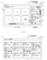
- FIG. 3 is a diagram showing an example of the home screen 100 displayed on the display section 41a of the touch panel display 41 of the operation panel 40 according to the embodiment.
- Home screen 100 is an example of a first history screen.
- the home screen 100 is, for example, a screen that is displayed when the user starts using the image processing device 1. From another perspective, the home screen 100 is displayed when the image processing device 1 is powered on, when the image processing device 1 returns from sleep mode, and/or when the user authentication in the image processing device 1 is successful. , is the screen that will be launched.
- a menu area 110 and a history area 120 are displayed side by side.
- the menu area 110 and the history area 120 are configured by dividing the home screen 100 into two left and right.
- the menu area 110 may be referred to as a main display area.
- History area 120 may be referred to as a timeline area.
- each history button displayed in the history area 120 is a history button 121 (121a to 121c) that individually displays information on completed image processing for each image process. That is, each history button 121 is associated with completed image processing (specifically, completed image processing job).
- the information displayed on the button may be text or a symbol image.
- the button does not have to imitate a physical button.
- a button may be indicated only by text and/or a symbol image and may not have a border surrounding the text and/or symbol image.
- the boundary between the area that accepts the user's operation and the surrounding area does not need to be expressed by a frame line or a difference in color.
- the menu area 110 has a plurality of function buttons 111 corresponding to the type of image processing (in the example of FIG. 3, "copy”, “print”, “scan”, “FAX”, "mail”, and “document box”). (111a, 111b,). Menu area 110 may be scrollable by scroll bar 112. Although an example is shown in which the scrolling direction is the left-right direction, the scrolling direction may be the up-down direction.
- the number of function buttons 111 and the types of functions corresponding to the function buttons 111 may be set as appropriate.
- the function button 111 may be referred to by the text displayed within the function button 111.
- examples of the function buttons 111 include a copy button 111a, a print button 111b, a scan button 111c, a FAX button 111d, a mail button 111e, and a document box button 111f.
- the control unit 50 controls the screen displayed on the display unit 41a to perform an operation related to the function corresponding to the function button 111.
- the display unit 41a is controlled to switch to the screen shown in FIG.
- the control unit 50 switches from the home screen 100 to the copy screen 130 shown in FIG. 4.
- the control unit 50 controls the image processing unit 3 to execute copying.
- the control unit 50 controls the display unit 41a to switch from the copy screen 130 to the home screen 100.
- control unit 50 may control the image processing unit 3 to perform image processing (for example, copying) when the function button 111 is tapped.
- Image processing conditions for example, copy settings
- the history area 120 shown in FIG. 3 is a display area that shows the history of image processing performed in the past.
- the position, shape, and area of the history area 120 are arbitrary.
- the history area 120 is located on one horizontal side (the right side in the illustrated example) of the rectangular home screen 100 whose longitudinal direction is the horizontal direction, and whose longitudinal direction is the vertical direction. It is said to have a rectangular shape.
- the width of the history area 120 is less than 1/2 or less than 1/3 of the width of the home screen 100.
- most of the home screen 100 (for example, 80% or more) excluding the history area 120 is a menu area 110.
- History area 120 may be scrollable by scroll bar 122. Although an example is shown in which the scrolling direction is the up-down direction, the scrolling direction may be the left-right direction.
- the maximum number of history buttons 121 that can be displayed by scrolling in the history area 120 is predetermined. For example, in the history area 120, history buttons 121 for the most recent n jobs (n ⁇ 2) among completed image processing jobs can be displayed by scrolling. In the example of FIG. 3, the number of history buttons 121 that can be displayed at one time in the history area 120 is three. However, the number of history buttons 121 that can be displayed at one time in the history area 120 may be two or four.
- the plurality of history buttons 121 are arranged in a line in a predetermined direction in the order of date and time when the image processing corresponding to the history button 121 was executed (that is, in chronological order). .
- the plurality of history buttons 121 can be arranged in any direction.
- the plurality of history buttons 121 may be arranged from one side to the other in the arrangement direction (from top to bottom in the illustrated example), in chronological order (as in the illustrated example), or in chronological order, or in chronological order.
- By performing a predetermined operation on the operation panel 40 it may be possible to switch between the newest order and the oldest order. Note that in the description of this embodiment, for convenience, it is assumed that the items are arranged in chronological order.
- the history button 121a corresponding to the newest completed image processing is arranged at the top
- the history button 121n corresponding to the n-th job which is the oldest completed image processing, is arranged at the bottom. .
- the control unit 50 When image processing is executed via an operation on the function button 111 or an operation on the history button 121, the control unit 50 adds a new history button 121 related to the image processing. If the image processing on which the history button 121 was added is the same as the new image processing performed via the operation on the history button 121, even if the history button 121 is newly added. Alternatively, only the execution date and time of the image processing corresponding to the operated history button 121 may be updated (from another point of view, the display position of the history button 121 may be changed). Here, the image processing being the same may mean, for example, being the same except for the execution date and time. Note that, unlike the description of this embodiment, the history button 121 does not need to be added for image processing executed via an operation on the history button 121.
- the type of image processing for which the history button 121 is generated is arbitrary. For example, even if the image processing device 1 has the six functions illustrated in the menu area 110, the history button 121 does not need to be generated for all of them.
- the history button 121 may be generated only for image processing in which printing is performed by the image processing apparatus 1, such as "copy” and “print” (and printing in a "box”). Further, for example, the history button 121 may be generated only for image processing in which scanning is performed by the image processing apparatus 1, such as “copy”, “scan”, “FAX”, and "email”. Further, for example, the history button 121 may be generated only for image processing in which no communication is performed, such as "copy,” “print,” and “scan” (and printing in a "box”).
- the history button 121 may or may not be added for image processing performed by transmitting a signal including a print job or the like from another device (for example, a PC) to the communication unit 30. If added, for example, when a user who sent a print job from a PC to the image processing device 1 confirms a printing failure in front of the image processing device 1, the user can reprint via the history button 121. can.
- the number of history buttons 121 (including those displayed by scrolling) that can be displayed in the history area 120 is limited to a predetermined upper limit value (n) or less. Therefore, history buttons 121 are added, and after the number of history buttons 121 reaches the upper limit, when a new history button 121 is added, the oldest history button 121 is deleted. In other words, the oldest history button 121 cannot be displayed.
- the specific value of the upper limit value (n) is arbitrary, and is, for example, 5, 10, or 20.
- the upper limit value may be set by the manufacturer of the image processing device 1 and cannot be changed by the administrator or user of the image processing device 1, or may be settable by the administrator of the image processing device 1. Good too. In an embodiment in which the display mode of the history area 120 can be made different for each user, the upper limit value may be settable by the user.
- Each history button 121 includes (shows) information on the corresponding image processing.
- the information includes, for example, the date and time when the image processing was performed, the type of image processing, the conditions (setting contents) of the image processing, and the name of the user who performed the image processing.
- Other examples include communication destinations (transmission destinations and/or reception destinations) in the FAX function and/or mail function. That is, each history button 121 displays the type of completed image processing, the setting contents of the completed image processing, the processing date and time of the completed image processing, the user name corresponding to the completed image processing, and the information of the completed image processing. Information on at least one of the transmission destinations is shown. This makes it easy for the user to specify the corresponding completed image processing based on the information indicated by each history button 121.
- the type of image processing information included in the history buttons 121 may be the same or different between the history buttons 121.
- the type of information displayed on the history button 121 may differ depending on the type of image processing. More specifically, the history button 121 whose image processing type is copy does not have an item for displaying the communication destination, while the history button 121 whose image processing type is fax or email does not have an item for displaying the communication destination. It may also have an item for displaying the destination.
- FIG. 5 is a diagram showing an example of a screen display when the history area 120 (history button) is operated according to the embodiment. In the example of FIG. 5, it is assumed that the history button 121b regarding FAX executed in the past has been operated.
- the history usage screen 210 shown in FIG. 5 is a screen for setting the conditions to be applied this time, with the past image processing conditions (setting contents) corresponding to the operated history button as initial values.
- the history usage screen 210 allows the user to reuse past settings and smoothly and quickly set the settings to be applied this time.
- Such a display operation of the history usage screen 210 is a general display operation when the history area 120 is used.
- the history usage screen 210 maintains the history area 120 and uses the area corresponding to the menu area 110 on the home screen 100 as the history usage area 150.
- the history usage area 150 includes, for example, a plurality of setting buttons 211 (211a, 211b, . . . ) for setting setting contents (here, FAX conditions), and an execution button 212 for instructing execution of FAX. , and a return button 213 for returning to the home screen 100.
- the setting button 211 displays information indicating the type of setting item corresponding to itself. Furthermore, the setting button 211 may display information indicating the setting state of the item corresponding to itself. In the illustrated example, the type of setting item is shown above the setting button 211, and the current setting state of the item is shown below the setting button 211.
- the number and types of setting buttons 211 are arbitrary.
- the setting buttons 211 include a destination button 211a, a one-sided/double-sided button 211b, a density button 211c, and a group of destination designation buttons 211d. Since these are common, explanations will be omitted.
- the destination button 211a, the one-sided/double-sided button 211b, and the density button 211c display conditions for previously executed faxes as initial values. If these initial values are used as they are, by operating (tapping) the execution button 212, the user can smoothly and quickly perform a fax under the same conditions as those used for previously executed faxes.
- the control unit 50 controls the image processing unit 3 to execute the FAX under partially changed conditions. Note that when the button for returning to the home screen 100 is tapped, or when a certain period of time has elapsed, the control unit 50 controls the display unit 41a to switch to the home screen 100. Further, the layout of the various parts described above is arbitrary, and FIG. 5 is only an example.
- the initial setting may be the setting when the image processing corresponding to the history button 121 was performed.
- the settings when the image processing corresponding to the history button 121 was performed may be set as initial settings.
- configurable items for example, processing conditions
- the number and type of setting buttons 211 in other words, setting items displayed on the history usage screen 210 may change. .
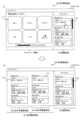
- FIG. 6 is a diagram illustrating an example of an operation for expanding the history area 120 according to the embodiment.
- the display unit 41a includes a menu area 110 in which function buttons 111 corresponding to a plurality of functions are arranged, and a history area 120 in which history buttons 121 corresponding to completed image processing are arranged.
- a first history screen (home screen) 100 is displayed in which , and are arranged.
- the control unit 50 controls the display unit 41a to switch from the first history screen 100 shown in FIG. 6(a) to the second history screen 200 shown in FIG. 6(b) in response to a user operation on the operation panel 40. do.
- the history area 120 is expanded. Thereby, it becomes possible to expand the history area 120 according to user operations, and it is possible to improve convenience for the user who uses the history button 121.
- the second history screen 200 is a screen that does not include the menu area 110 but includes an expanded history area 120.
- the second history screen 200 is a history screen in which the history area 120 is displayed on the entire screen.
- the history buttons 121 can be arranged over the entire screen, and more history buttons 121 can be displayed.
- the operation of switching from the second history screen 200 to the first history screen 100 is performed by pressing the "home button (back button)" (not shown) included in the second history screen 200. It may be an operation.
- the number of history buttons 121 displayed on the second history screen 200 is greater than the number of history buttons 121 displayed on the first history screen 100 shown in FIG. 6(a). .
- the number of history buttons 121 displayed on the first history screen 100 shown in FIG. 6(a) is three
- the number of history buttons 121 displayed on the second history screen 200 shown in FIG. 6(b) is three.
- the number of is 12.
- the desired history button 121 does not exist among the three history buttons 121a to 121c that are initially displayed, the user scrolls the history area 120 to search for the desired history button 121. There is a need to.
- since more history buttons 121 are displayed on the second history screen 200 it becomes easier to search for a desired history button 121.
- the history buttons 121 for up to the most recent 12 jobs among the completed image processing jobs can be displayed at once (that is, they can be displayed without scrolling).
- a scroll bar may be provided on the second history screen 200 so that history buttons 121 corresponding to completed image processing older than the most recent 12 jobs can be displayed by scrolling.
- the history buttons 121a to 121l are divided into a row of history buttons 121a to 121c, a row of history buttons 121d to 121f, a row of history buttons 121g to 121i, and a row of history buttons 121a to 121c. It includes a total of four columns: 121j to 121l.
- each column the items are arranged in chronological order from top to bottom. That is, the history buttons 121 are arranged from top to bottom in chronological order, with line breaks to the right.
- the chronological order can be the same as that of the first history screen 100, and the user's operability can be improved.
- the second history screen 200 may be arranged such that the history buttons 121 are arranged from left to right in chronological order, with line breaks in the downward direction.
- the size of the history button 121 on the second history screen 200 is equal to the size of the history button 121 on the first history screen 100. Thereby, the same operational feeling of the history button 121 as in the first history screen 100 can be maintained on the second history screen 200 as well. However, the size of the history button 121 on the second history screen 200 may be larger than the size of the history button 121 on the first history screen 100.
- the amount of information displayed on the history button 121 on the second history screen 200 may be greater than the amount of information displayed on the history button 121 on the first history screen 100.
- the history button 121 on the second history screen 200 includes (shows) more information on the corresponding image processing than the first history screen 100.
- the history button 121a on the first history screen 100 displays "Copy” as the type of completed image processing, "Color 100% A4" as the setting content of the completed image processing, and "Color 100% A4" as the setting content of the completed image processing. "08/20 9:15" is included as the processing date and time.
- the history button 121a of the second history screen 200 may further include more detailed setting contents, such as "density" and/or "page aggregation" in addition to this information.
- the history button 121a of the second history screen 200 may further include the user name corresponding to the completed image processing. In this way, by increasing the amount of information displayed by the history button 121 on the second history screen 200, it becomes easier for the user to search for the desired history button 121.
- the second history screen 200 may include a group history button, which is the history button 121, associated with a group in which a plurality of completed image processes are classified according to classification conditions.
- the classification condition may be the time of image processing (eg, date and time) or the type of image processing (ie, function).
- the control unit 50 may expand and display the history buttons 121 of each completed image processing corresponding to the selected group history button. Providing such a group history button makes it easy for the user to search for a desired history button 121.
- the first history screen 100 includes a dedicated button 123 for switching from the first history screen 100 to the second history screen 200.
- the control unit 50 controls the display unit 41a to switch from the first history screen 100 to the second history screen 200 in response to the operation unit 41b receiving a user operation to select the dedicated button 123.
- the dedicated button 123 is arranged in the history area 120 (specifically, at the top of the history area 120) of the first history screen 100, and the text "Extended Display" is attached.
- the dedicated button 123 does not need to have any text attached to it.
- the dedicated button 123 may be attached with a symbol image indicating full screen display.
- ⁇ Trigger pattern (2) from the first history screen 100 to the second history screen 200
- the control unit 50 controls the The display section 41a is controlled to switch from the first history screen 100 to the second history screen 200. That is, when any history button 121 in the first history screen 100 is operated, the control unit 50 switches from the first history screen 100 to the second history screen 200. Thereby, the dedicated button 123 like pattern (1) can be made unnecessary.
- the control unit 50 controls the display unit 41a to switch from the first history screen 100 to the second history screen 200 in response to the operation unit 41b accepting a scroll operation on the history area 120 of the first history screen 100. You can. Thereby, it is possible to appropriately switch from the first history screen 100 to the second history screen 200 under a situation where the user is searching for a desired history button 121.
- the control unit 50 upon receiving an operation (slide operation, drag operation) to move the boundary between the menu area 110 and the history area 120 from the history area 120 side to the menu area 110 side on the first history screen 100, the control unit 50 Accordingly, the display section 41a is controlled to switch from the first history screen 100 to the second history screen 200. In that case, if the operation for moving the boundary is completed before reaching the left edge of the screen, the control unit 50 may fix the boundary at the time of completion. As a result, in the second history screen 200, the history area 120 may be expanded while the menu area 110 may be displayed in a reduced state.
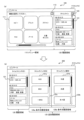
- FIG. 7 is a diagram showing an example of a control flow of the image processing device 1 according to the embodiment.
- one of the history buttons 121 is operated by the user.
- step S1 the control unit 50 displays a menu area 110 in which function buttons 111 corresponding to the type of image processing (i.e., multiple functions of the image processing apparatus 1) are arranged, and history buttons corresponding to completed image processing.
- the display unit 41a is controlled to display the first history screen 100 in which the arranged history areas 120 are arranged.
- step S2 the control unit 50 determines whether the operation unit 41b has received a user operation to switch from the first history screen 100 to the second history screen 200.
- the user operation is, for example, one of the trigger patterns (1) to (3) described above. If it is determined that the user operation has been accepted (step S2: YES), the control unit 50 advances the process to step S3. On the other hand, if it is determined that the user operation has not been accepted (step S2: NO), the control unit 50 advances the process to step S4.
- step S3 the control unit 50 controls the display unit 41a to switch from the first history screen 100 to the second history screen 200 in which the history area 120 is expanded.
- step S4 the operation unit 41b accepts a user operation on any of the history buttons 121.
- step S5 the control unit 50 determines whether the user operation received in step S4 is a predetermined user operation.
- the predetermined user operation is a long press operation of the history button 121 or a continuous press operation (eg, double tap) of the history button 121. If it is determined that the user operation received in step S4 is a predetermined user operation (step S5: YES), the control unit 50 skips steps S6 and S7 and advances the process to step S8. On the other hand, if it is determined that the user operation received in step S4 is not the predetermined user operation (step S5: NO), the control unit 50 advances the process to step S6.
- the control unit 50 when the operation unit 41b receives a predetermined user operation on the history button 121, the control unit 50 separately receives an execution instruction from the user to instruct the execution of image processing corresponding to the history button 121. Even if it is not accepted, the image processing is executed using a predetermined user operation as a trigger. This makes it possible to use the history button 121 to cause the image processing apparatus 1 to execute image processing more quickly.
- step S6 the control unit 50 uses the history usage screen 210 (see FIG.
- the display unit 41a is controlled to display (see 5).
- step S7 while the history usage screen 210 is displayed, the operation unit 41b receives an execution instruction (that is, an operation on the execution button) to instruct the execution of image processing from the user.
- an execution instruction that is, an operation on the execution button
- step S8 the control unit 50 controls the image processing unit 3 to execute the instructed image processing.
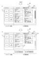
- FIG. 8 is a diagram for explaining this modification example.
- the second history screen 200 is a screen that does not include the menu area 110 but includes an expanded history area 120.
- the second history screen 200 is displayed in response to the above-mentioned trigger pattern (2), that is, the operation unit 41b receives a user operation to select the history button 121 in the first history screen 100.
- the second history screen 200 includes a history area 120 and an additional history area 125 added by expanding the history area 120.
- the position of the history area 120 is maintained, and the additional history area 125 is arranged at a position corresponding to the position of the menu area 110 on the first history screen 100. That is, the area corresponding to the menu area 110 of the first history screen 100 is used as the additional history area 125 of the second history screen 200, and the history area 120 is arranged in the same manner as the first history screen 100. Thereby, the area corresponding to the menu area 110 can be effectively utilized for displaying history information.
- the additional history area 125 of the second history screen 200 shown in FIG. 8(b) includes a plurality of condition-specific history areas 126, each associated with a classification condition.
- history buttons 121 corresponding to completed image processing that match the corresponding classification condition are arranged.
- the plurality of condition-specific history areas 126 two condition-specific history areas 126a and 126b each configured in the vertical direction are illustrated.
- the second history screen 200 may include two or more condition-based history areas 126. This allows the history buttons 121 to be displayed according to classification conditions, making it easier for the user to search for the desired history button 121.
- the additional history area 125 or each condition-specific history area 126 may be scrollable in the vertical direction.
- the plurality of condition-specific history areas 126 are a plurality of function-specific history areas corresponding to a plurality of functions (image processing types) of the image processing device 1, a plurality of date-specific history areas corresponding to a plurality of dates, or a plurality of date-specific history areas corresponding to a plurality of dates. These are a plurality of period-specific history areas corresponding to a plurality of periods with different values.
- the plurality of condition-specific history areas 126 are a plurality of date-specific history areas corresponding to a plurality of dates. This makes it easy for the user to search for the desired history button 121 by date.
- the condition-specific history area 126a includes a history button 121 for each completed image process that belongs to the current date, and includes a history button 121 for each completed image process that belongs to a specific date in the past than the current day. .
- FIG. 9 is a diagram for explaining this modification example.
- the second history screen 200 includes a history area 120 and an additional history area 125 added by expanding the history area 120.
- the history area 120 is moved to a position corresponding to the position of the menu area 110 of the first history screen 100, and the additional history area 125 is moved to the position of the history area 120 of the first history screen 100. is placed at the position corresponding to.
- the history area 120 that was placed on the right side of the first history screen 100 is placed on the left side of the second history screen 200.
- the additional history area 125 is arranged to cover the right end position.
- trigger patterns (1) and (2) when switching to the second history screen 200 in response to a user operation on the history area 120 of the first history screen 100, the user's line of sight and finger are placed on the right side of the screen. It is thought that it is directed towards. Therefore, by arranging the additional history area 125 so as to cover the right end position, the user can easily operate the history button 121 in the additional history area 125. Note that this arrangement method (layout) of the additional history area 125 is also applicable to the first modification example described above and the modification example described later. However, similarly to the first modification example described above, in the second history screen 200, the position of the history area 120 is maintained, and the additional history area 125 is located at a position corresponding to the position of the menu area 110 on the first history screen 100. may be placed in
- the additional history area 125 of the second history screen 200 shown in FIG. 9 includes a plurality of condition-based history areas 126, each associated with a classification condition.
- history buttons 121 corresponding to completed image processing that match the corresponding classification condition are arranged.
- the plurality of condition-specific history areas 126 two condition-specific history areas 126a and 126b each configured in the vertical direction are illustrated. Further, each condition-specific history area 126 is configured to be scrollable in the vertical direction.
- the plurality of condition-specific history areas 126 are a plurality of period-specific history areas corresponding to a plurality of periods each having a different time length.
- the condition-specific history area 126a is a date-specific history area
- the condition-specific history area 126b is a weekly history area. If the screen size allows, you may add a monthly history area.
- Group history buttons, which are history buttons 121, are arranged in each condition-based history area 126, which are history buttons 121 associated with groups into which a plurality of completed image processes are classified according to classification conditions.
- the control unit 50 causes the display unit to expand and display the history buttons of each completed image processing belonging to the group corresponding to the operated group history button. 41a.
- a plurality of history buttons 121a by date are arranged in the history region 126a by condition
- a plurality of history buttons 121a by week are arranged in the history region 126b by condition.
- the control unit 50 causes the display unit to expand and display the history buttons of each completed image processing that belong to the date corresponding to the operated history button 121a. 41a.
- the control unit 50 expands and displays the history buttons of each completed image processing belonging to the week corresponding to the operated history button 121a. Controls the display section 41a.
- FIG. 10 is a diagram for explaining an example of a trigger for switching to the second history screen 200 according to this modification example.
- the first history screen 100 includes a dedicated button 123 for switching from the first history screen 100 to the second history screen 200.
- the control unit 50 causes the display unit to switch from the first history screen 100 to the second history screen 200 shown in FIG. 41a.
- the dedicated button 123 is arranged at the top of the history area 120 of the first history screen 100, and a symbol image indicating full-screen display is attached.
- a dedicated button 113 for displaying the menu area 110 in full screen is arranged in the menu area 110 of the first history screen 100.
- the control unit 50 controls the display unit to display the menu area 110 in full screen, that is, to display a home screen that does not include the history area 120. 41a. In the menu area 110 expanded in this way, more function buttons 111 can be displayed.
- FIG. 11 is a diagram for explaining this modification example.
- the reduced menu area 110 is on the left side
- the expanded history area 120 is on the right side.
- the control unit 50 switches to the layout shown in FIG. 11(c).
- the control unit 50 displays the first history screen 100 shown in FIG. 11(a). Switch.
- the reduced menu area 110 is on the right side, and the expanded history area 120 is on the left side.
- the control unit 50 switches to the layout shown in FIG. 11(b).
- the control unit 50 displays the first history screen 100 shown in FIG. 11(a). Switch.
- the first history screen 100 shown in FIG. 11(a) has a dedicated button 123a for switching to the layout of the second history screen 200 shown in FIG. 11(b), and the second history screen 200 shown in FIG. 11(c).
- a dedicated button 123b for switching to a layout is included.
- the control unit 50 switches to the layout shown in FIG. 11(b).
- the control unit 50 switches to the layout shown in FIG. 11(c).
- control unit 50 switches from the second history screen 200 to the first history screen 100 in response to the operation unit 41b receiving a user operation to select the reduced menu area 110.
- the display unit 41a may also be controlled.
- the history area 120 of the second history screen 200 may be provided with a condition-based history area 126.
- FIG. 12 is a diagram for explaining this modification example.
- the control unit 50 in response to the operation unit 41b receiving a user operation specifying a classification condition, the control unit 50 causes the display unit 41a to display a plurality of condition-specific history areas 126 according to the specified classification condition. control. For example, in response to the operation unit 41b receiving a user operation to select the "arrange by function" button 127a on the second history screen 200 shown in FIG. As shown in FIG. 3, the display unit 41a is controlled to display the condition-specific history area 126 classified according to function. Note that when the operation unit 41b receives a user operation to select the “return” button 127b arranged in the history area 120 shown in FIG. 12(a), the control unit 50 switches to the first history screen 100.
- a plurality of condition-specific history areas 126 provided in the history area 120 are a plurality of function-specific history areas corresponding to a plurality of functions of the image processing device 1.
- history buttons 121 for completed image processing that match the "copy” function are arranged in chronological order from top to bottom.
- history buttons 121 for completed image processing that match the "FAX" function are arranged in chronological order from top to bottom.
- the control unit 50 changes the history of the condition-specific history area 126 for a function different from "copy” and "FAX".
- the display section 41a is controlled to display in the area 120.
- the display section 41a is controlled to display the condition-specific history area 126. Note that when the operation unit 41b receives a user operation to select the “return” button 127d arranged in the history area 120 shown in FIG. 12(b), the control unit 50 switches to the first history screen 100.
- the history usage screen 210 may be regarded as a type of the second history screen 200. Further, the history usage area 150 on the history usage screen 210 may be regarded as a part of the expanded history area 120, specifically, the additional history area 125 added by expanding the history area 120. In that case, as shown in FIG. 13, on the history usage screen 210 (second history screen 200), the history area 120 is moved to a position corresponding to the position of the menu area 110 on the first history screen 100, and The usage area 150 (additional history area 125) may be arranged at a position corresponding to the position of the history area 120 on the first history screen 100.
- the history area 120 that was placed on the right side of the first history screen 100 is placed on the left side of the history usage screen 210.
- the history usage area 150 (additional history area 125) is arranged to cover the right end position.
- a program may be provided that causes the image processing device 1 to execute the operations according to the embodiments described above.
- the program may be recorded on a computer readable medium.
- the computer-readable medium on which the program is recorded may be a non-transitory recording medium.
- the non-transitory recording medium is not particularly limited, and may be, for example, a recording medium such as a CD-ROM or a DVD-ROM.
- the circuits that execute each process performed by the image processing device 1 may be integrated, and at least a portion of the image processing device 1 may be configured as a semiconductor integrated circuit (chip set, SoC).
- the words “based on” and “in accordance with” do not mean “based solely on” or “in accordance with” unless expressly stated otherwise.
- Reference to “based on” means both “based solely on” and “based at least in part on.”
- the phrase “in accordance with” means both “in accordance with” and “in accordance with, at least in part.”
- the terms “include”, “comprise”, and variations thereof do not mean to include only the listed items, and may include only the listed items, or may include only the listed items. In addition, it means that further items may be included.
- the term “or” is not intended to be exclusive OR. Furthermore, any reference to elements using the designations "first,” “second,” etc.
- An image processing device 1 that executes a plurality of functions related to image processing, A first history screen 100 is displayed in which a menu area 110 in which function buttons 111 corresponding to the plurality of functions are arranged and a history area 120 in which history buttons 121 corresponding to completed image processing are arranged are arranged.
- An operation panel 40 having a display section 41a; a control unit 50 that controls the display unit 41a to switch from the first history screen 100 to a second history screen 200 in which the history area 120 is expanded in accordance with a user operation on the operation panel 40; Image processing device 1.
- the amount of information displayed on the history button 121 on the second history screen 200 is larger than the amount of information displayed on the history button 121 on the first history screen 100. image processing device 1.
- the second history screen 200 includes group history buttons 121a/121b, which are the history buttons 121 associated with groups in which a plurality of completed image processes are classified according to classification conditions. Image processing device 1 as described.
- the first history screen 100 includes a dedicated button 123 for switching from the first history screen 100 to the second history screen 200,
- the control unit 50 controls the display unit 41a to switch from the first history screen 100 to the second history screen 200 in response to receiving a user operation to select the dedicated button 123. 5.
- Image processing device 1 according to any one of 5.
- Appendix 7 The image processing device 1 according to appendix 6, wherein the dedicated button 123 is arranged in the history area 120 of the first history screen 100.
- the control unit 50 controls the display to switch from the first history screen 100 to the second history screen 200 in response to receiving a user operation of selecting the history button 121 in the first history screen 100.
- the image processing device 1 according to any one of Supplementary Notes 1 to 5, which controls the unit 41a.
- the control unit 50 switches from the first history screen 100 to the second history screen 200 in response to receiving an operation on the boundary between the menu area 110 and the history area 120 on the first history screen 100.
- the image processing device 1 according to any one of Supplementary Notes 1 to 5, wherein the display unit 41a is controlled to switch.
- control unit 50 When the control unit 50 receives a predetermined user operation on the history button 121, the control unit 50 triggers the predetermined user operation even if it does not separately receive an execution instruction from the user to instruct the execution of image processing corresponding to the history button 121.
- the image processing device 1 according to any one of Supplementary Notes 1 to 10, which performs the image processing as follows.
- Appendix 12 The image processing device 1 according to appendix 11, wherein the predetermined user operation is a long press operation of the history button 121 or a continuous press operation of the history button 121.
- the second history screen 200 includes the history area 120 and an additional history area 125 added by expanding the history area 120, In the second history screen 200, the position of the history area 120 is maintained, and the additional history area 125 is arranged at a position corresponding to the position of the menu area 110 on the first history screen 100. 12. Image processing device 1 according to any one of 12.
- the second history screen 200 includes the history area 120 and an additional history area 125 added by expanding the history area 120, In the second history screen 200, the history area 120 is moved to a position corresponding to the position of the menu area 110 on the first history screen 100, and the additional history area 125 is moved to a position corresponding to the position of the menu area 110 on the first history screen 100.
- the image processing device 1 according to supplementary note 14, wherein the image processing device 1 is arranged at a position corresponding to the position of the history area 120.
- the second history screen 200 is a screen that includes the expanded history area 120 and the menu area 110 that has been reduced due to the expansion of the history area 120.
- Image processing device 1 The second history screen 200 is a screen that includes the expanded history area 120 and the menu area 110 that has been reduced due to the expansion of the history area 120.
- the control unit 50 controls the display unit 41a to switch from the second history screen 200 to the first history screen 100 in response to receiving a user operation to select the reduced menu area 110.
- Image processing device 1 according to appendix 16.
- the second history screen 200 includes dedicated buttons 124a/124c for switching the positional relationship between the reduced menu area 110 and the expanded history area 120,
- the control unit 50 adjusts the positions of the reduced menu area 110 and the expanded history area 120 in response to receiving a user operation to select the dedicated button 124a/124c on the second history screen 200.
- the image processing device 1 according to supplementary note 16 or 17, wherein the display unit 41a is controlled to change the relationship.
- the second history screen 200 includes a plurality of condition-specific history areas 126 each associated with a classification condition, The image processing device 1 according to any one of Supplementary Notes 1 to 18, wherein history buttons 121 corresponding to completed image processing that match the corresponding classification conditions are arranged in each of the plurality of condition-specific history areas 126.
- the plurality of condition-specific history areas 126 may include a plurality of function-specific history areas corresponding to the plurality of functions, a plurality of date-specific history areas corresponding to a plurality of dates, or a plurality of condition-specific history areas corresponding to a plurality of periods each having a different time length.
- control unit 50 controls the display unit 41a to display the plurality of condition-specific history areas 126 according to the specified classification condition.
- Image processing device 1 according to item 19 or 20.
- a control method for controlling an image processing device 1 that executes a plurality of functions related to image processing comprising: A first history screen 100 in which a menu area 110 in which function buttons 111 corresponding to the plurality of functions are arranged and a history area 120 in which history buttons 121 corresponding to completed image processing are arranged are displayed on the operation panel. 40 steps, A control method comprising the step of switching from the first history screen 100 to a second history screen 200 in which the history area 120 is expanded according to a user operation on the operation panel 40.
- An image processing device 1 that executes multiple functions related to image processing, A first history screen 100 in which a menu area 110 in which function buttons 111 corresponding to the plurality of functions are arranged and a history area 120 in which history buttons 121 corresponding to completed image processing are arranged are displayed on the operation panel. 40 steps, A program that executes a step of switching from the first history screen 100 to a second history screen 200 in which the history area 120 is expanded in response to a user operation on the operation panel 40.
- Image processing device 3 Image processing section 5: Bus 10: Printer 20: Scanner 30: Communication section 40: Operation panel 41: Touch panel display 41a: Display section 41b: Operation section 41c: Physical button 50: Control section 60: Memory Section 71: Paper feed tray 72: Paper output tray 73: Original table
Landscapes
- Engineering & Computer Science (AREA)
- Theoretical Computer Science (AREA)
- General Engineering & Computer Science (AREA)
- Human Computer Interaction (AREA)
- Physics & Mathematics (AREA)
- General Physics & Mathematics (AREA)
- User Interface Of Digital Computer (AREA)
- Accessory Devices And Overall Control Thereof (AREA)
- Control Or Security For Electrophotography (AREA)
- Facsimiles In General (AREA)
- Input From Keyboards Or The Like (AREA)
Priority Applications (8)
| Application Number | Priority Date | Filing Date | Title |
|---|---|---|---|
| JP2023546331A JPWO2024009426A1 (https=) | 2022-07-06 | 2022-07-06 | |
| PCT/JP2022/026813 WO2024009426A1 (ja) | 2022-07-06 | 2022-07-06 | 画像処理装置、制御方法、及びプログラム |
| CN202280098791.9A CN119631047A (zh) | 2022-07-06 | 2022-07-06 | 图像处理装置、控制方法和程序 |
| DE112022007488.4T DE112022007488T5 (de) | 2022-07-06 | 2022-07-06 | Bildverarbeitungsvorrichtung, steuerungsverfahren und programm |
| JP2024089079A JP7636614B2 (ja) | 2022-07-06 | 2024-05-31 | 画像処理装置、制御方法、及びプログラム |
| JP2024155371A JP7626897B2 (ja) | 2022-07-06 | 2024-09-09 | 画像処理装置、制御方法、及びプログラム |
| US19/002,713 US20250130750A1 (en) | 2022-07-06 | 2024-12-27 | Image processing apparatus, control method, and program |
| JP2025009564A JP2025069224A (ja) | 2022-07-06 | 2025-01-23 | 画像処理装置、制御方法、及びプログラム |
Applications Claiming Priority (1)
| Application Number | Priority Date | Filing Date | Title |
|---|---|---|---|
| PCT/JP2022/026813 WO2024009426A1 (ja) | 2022-07-06 | 2022-07-06 | 画像処理装置、制御方法、及びプログラム |
Related Child Applications (1)
| Application Number | Title | Priority Date | Filing Date |
|---|---|---|---|
| US19/002,713 Continuation US20250130750A1 (en) | 2022-07-06 | 2024-12-27 | Image processing apparatus, control method, and program |
Publications (1)
| Publication Number | Publication Date |
|---|---|
| WO2024009426A1 true WO2024009426A1 (ja) | 2024-01-11 |
Family
ID=89453037
Family Applications (1)
| Application Number | Title | Priority Date | Filing Date |
|---|---|---|---|
| PCT/JP2022/026813 Ceased WO2024009426A1 (ja) | 2022-07-06 | 2022-07-06 | 画像処理装置、制御方法、及びプログラム |
Country Status (5)
| Country | Link |
|---|---|
| US (1) | US20250130750A1 (https=) |
| JP (4) | JPWO2024009426A1 (https=) |
| CN (1) | CN119631047A (https=) |
| DE (1) | DE112022007488T5 (https=) |
| WO (1) | WO2024009426A1 (https=) |
Citations (5)
| Publication number | Priority date | Publication date | Assignee | Title |
|---|---|---|---|---|
| JP2002216051A (ja) * | 2001-01-22 | 2002-08-02 | Fuji Photo Film Co Ltd | 注文受け付け方法及び装置 |
| WO2014103388A1 (ja) * | 2012-12-27 | 2014-07-03 | 株式会社 東芝 | 電子機器、表示方法、およびプログラム |
| JP2014522527A (ja) * | 2012-03-06 | 2014-09-04 | アップル インコーポレイテッド | 画像を閲覧するためのアプリケーション |
| JP2020181304A (ja) * | 2019-04-24 | 2020-11-05 | 京セラドキュメントソリューションズ株式会社 | 表示入力装置および画像形成装置 |
| JP2021175020A (ja) * | 2020-04-21 | 2021-11-01 | 京セラドキュメントソリューションズ株式会社 | 情報処理装置 |
Family Cites Families (3)
| Publication number | Priority date | Publication date | Assignee | Title |
|---|---|---|---|---|
| JP4905377B2 (ja) * | 2008-01-31 | 2012-03-28 | ブラザー工業株式会社 | 情報処理装置 |
| JP7460952B2 (ja) * | 2020-04-21 | 2024-04-03 | 京セラドキュメントソリューションズ株式会社 | 情報処理装置 |
| JP7460953B2 (ja) * | 2020-04-21 | 2024-04-03 | 京セラドキュメントソリューションズ株式会社 | 情報処理装置 |
-
2022
- 2022-07-06 JP JP2023546331A patent/JPWO2024009426A1/ja active Pending
- 2022-07-06 WO PCT/JP2022/026813 patent/WO2024009426A1/ja not_active Ceased
- 2022-07-06 DE DE112022007488.4T patent/DE112022007488T5/de active Pending
- 2022-07-06 CN CN202280098791.9A patent/CN119631047A/zh active Pending
-
2024
- 2024-05-31 JP JP2024089079A patent/JP7636614B2/ja active Active
- 2024-09-09 JP JP2024155371A patent/JP7626897B2/ja active Active
- 2024-12-27 US US19/002,713 patent/US20250130750A1/en active Pending
-
2025
- 2025-01-23 JP JP2025009564A patent/JP2025069224A/ja active Pending
Patent Citations (5)
| Publication number | Priority date | Publication date | Assignee | Title |
|---|---|---|---|---|
| JP2002216051A (ja) * | 2001-01-22 | 2002-08-02 | Fuji Photo Film Co Ltd | 注文受け付け方法及び装置 |
| JP2014522527A (ja) * | 2012-03-06 | 2014-09-04 | アップル インコーポレイテッド | 画像を閲覧するためのアプリケーション |
| WO2014103388A1 (ja) * | 2012-12-27 | 2014-07-03 | 株式会社 東芝 | 電子機器、表示方法、およびプログラム |
| JP2020181304A (ja) * | 2019-04-24 | 2020-11-05 | 京セラドキュメントソリューションズ株式会社 | 表示入力装置および画像形成装置 |
| JP2021175020A (ja) * | 2020-04-21 | 2021-11-01 | 京セラドキュメントソリューションズ株式会社 | 情報処理装置 |
Also Published As
| Publication number | Publication date |
|---|---|
| DE112022007488T5 (de) | 2025-04-17 |
| CN119631047A (zh) | 2025-03-14 |
| JPWO2024009426A1 (https=) | 2024-01-11 |
| JP2024107039A (ja) | 2024-08-08 |
| JP2024161286A (ja) | 2024-11-15 |
| JP7626897B2 (ja) | 2025-02-04 |
| JP7636614B2 (ja) | 2025-02-26 |
| JP2025069224A (ja) | 2025-04-30 |
| US20250130750A1 (en) | 2025-04-24 |
Similar Documents
| Publication | Publication Date | Title |
|---|---|---|
| US8115968B2 (en) | Image processing apparatus, computer program product, and preview image displaying method | |
| US8330989B2 (en) | Print control device for obtaining appropriate print results | |
| JP5577982B2 (ja) | 画像処理装置、その制御プログラム、および、その制御方法 | |
| CN101064758B (zh) | 图象处理装置和图象处理方法 | |
| JP2007088887A (ja) | スキャナおよびその操作メニュー表示制御方法 | |
| JP6662457B2 (ja) | 表示入力装置、画像形成装置、表示入力装置の制御方法 | |
| JP7626897B2 (ja) | 画像処理装置、制御方法、及びプログラム | |
| JP7677938B2 (ja) | 画像処理装置、制御方法、及び制御プログラム | |
| JP4785457B2 (ja) | 表示制御装置及び表示制御方法 | |
| JP3888195B2 (ja) | トリミング設定装置及び印刷装置 | |
| JP7473751B2 (ja) | 画像処理装置、制御方法、及び制御プログラム | |
| JP4788511B2 (ja) | 画像形成装置 | |
| JP4229054B2 (ja) | 画像処理装置 | |
| CN111917928B (zh) | 显示控制装置、具备其的图像形成装置以及显示控制方法 | |
| JP4798206B2 (ja) | 情報処理装置、処理実行装置及びプログラム | |
| US20220385775A1 (en) | Multifunction machine, display control method for multifunction machine, and non-transitory computer-readable storage medium | |
| US20220374175A1 (en) | Printing apparatus and method of producing printed item | |
| JP4764228B2 (ja) | 画像形成装置の端末装置およびその制御方法 | |
| JP2016024388A (ja) | 入力/表示装置および画像形成装置 | |
| JP2013005449A (ja) | 画像形成装置及びプログラム | |
| JP2006137134A (ja) | 画像形成装置,その操作パネル表示部の表示方法およびプログラム |
Legal Events
| Date | Code | Title | Description |
|---|---|---|---|
| WWE | Wipo information: entry into national phase |
Ref document number: 2023546331 Country of ref document: JP |
|
| 121 | Ep: the epo has been informed by wipo that ep was designated in this application |
Ref document number: 22950220 Country of ref document: EP Kind code of ref document: A1 |
|
| WWE | Wipo information: entry into national phase |
Ref document number: 202280098791.9 Country of ref document: CN |
|
| WWE | Wipo information: entry into national phase |
Ref document number: 112022007488 Country of ref document: DE |
|
| WWP | Wipo information: published in national office |
Ref document number: 202280098791.9 Country of ref document: CN |
|
| WWP | Wipo information: published in national office |
Ref document number: 112022007488 Country of ref document: DE |
|
| 122 | Ep: pct application non-entry in european phase |
Ref document number: 22950220 Country of ref document: EP Kind code of ref document: A1 |