WO2024009426A1 - Image processing device, control method, and program - Google Patents
Image processing device, control method, and program Download PDFInfo
- Publication number
- WO2024009426A1 WO2024009426A1 PCT/JP2022/026813 JP2022026813W WO2024009426A1 WO 2024009426 A1 WO2024009426 A1 WO 2024009426A1 JP 2022026813 W JP2022026813 W JP 2022026813W WO 2024009426 A1 WO2024009426 A1 WO 2024009426A1
- Authority
- WO
- WIPO (PCT)
- Prior art keywords
- history
- image processing
- area
- screen
- button
- Prior art date
Links
- 238000012545 processing Methods 0.000 title claims abstract description 239
- 238000000034 method Methods 0.000 title claims description 35
- 230000006870 function Effects 0.000 claims abstract description 80
- 230000004044 response Effects 0.000 claims abstract description 36
- 230000008569 process Effects 0.000 claims description 21
- 238000004148 unit process Methods 0.000 claims 1
- 238000004891 communication Methods 0.000 description 26
- 238000010586 diagram Methods 0.000 description 26
- 230000004048 modification Effects 0.000 description 23
- 238000012986 modification Methods 0.000 description 23
- 230000008859 change Effects 0.000 description 8
- 230000015654 memory Effects 0.000 description 4
- 230000007704 transition Effects 0.000 description 3
- 230000002776 aggregation Effects 0.000 description 2
- 238000004220 aggregation Methods 0.000 description 2
- 230000005540 biological transmission Effects 0.000 description 2
- 238000005401 electroluminescence Methods 0.000 description 2
- 238000003384 imaging method Methods 0.000 description 2
- 238000010079 rubber tapping Methods 0.000 description 2
- 238000006243 chemical reaction Methods 0.000 description 1
- 238000013461 design Methods 0.000 description 1
- 238000001514 detection method Methods 0.000 description 1
- 239000011521 glass Substances 0.000 description 1
- 230000006872 improvement Effects 0.000 description 1
- 239000004973 liquid crystal related substance Substances 0.000 description 1
- 230000002093 peripheral effect Effects 0.000 description 1
- 238000003825 pressing Methods 0.000 description 1
- 230000009467 reduction Effects 0.000 description 1
- 239000004065 semiconductor Substances 0.000 description 1
- 238000013519 translation Methods 0.000 description 1
- 230000003442 weekly effect Effects 0.000 description 1
Images


Classifications
-
- G—PHYSICS
- G06—COMPUTING; CALCULATING OR COUNTING
- G06F—ELECTRIC DIGITAL DATA PROCESSING
- G06F3/00—Input arrangements for transferring data to be processed into a form capable of being handled by the computer; Output arrangements for transferring data from processing unit to output unit, e.g. interface arrangements
- G06F3/01—Input arrangements or combined input and output arrangements for interaction between user and computer
- G06F3/048—Interaction techniques based on graphical user interfaces [GUI]
- G06F3/0481—Interaction techniques based on graphical user interfaces [GUI] based on specific properties of the displayed interaction object or a metaphor-based environment, e.g. interaction with desktop elements like windows or icons, or assisted by a cursor's changing behaviour or appearance
- G06F3/0482—Interaction with lists of selectable items, e.g. menus
Definitions
- the present disclosure relates to an image processing device, a control method, and a program.
- Patent Document 1 discloses a menu area in which function buttons corresponding to the type of image processing are arranged, and history buttons corresponding to image processing completed in the past (hereinafter referred to as "completed image processing") are arranged.
- An image processing apparatus is described that has an operation panel that displays history areas side by side.
- the image processing settings corresponding to the history button are reproduced, thereby saving the user the trouble of inputting the settings. be able to.
- the image processing device as described above has room for improvement in terms of further increasing the convenience for users who use the history button.
- the present disclosure provides an image processing device, a control method, and a program that can further improve user convenience.
- An image processing device is an image processing device that executes a plurality of functions related to image processing, and includes a menu area in which function buttons corresponding to the plurality of functions are arranged, and a completed image.
- an operation panel having a display section that displays a history area in which history buttons corresponding to processes are arranged; and a first history screen in which history buttons are arranged; and in response to a user operation on the operation panel, from the first history screen, and a control unit that controls the display unit to switch to a second history screen in which the history area is expanded.
- a control method is a control method for controlling an image processing apparatus that executes a plurality of functions related to image processing, the control method comprising: a menu area in which function buttons corresponding to the plurality of functions are arranged; , a history area in which history buttons corresponding to completed image processing are arranged, and displaying on an operation panel a first history screen in which history buttons corresponding to completed image processing are arranged; and switching to a second history screen in which the history area is expanded.
- a program includes an image processing device that executes a plurality of functions related to image processing, a menu area in which function buttons corresponding to the plurality of functions are arranged, and a menu area corresponding to completed image processing. displaying on an operation panel a history area in which history buttons are arranged; and expanding the history area from the first history screen in response to a user operation on the operation panel. and switching to the second history screen.
- FIG. 1 is a diagram showing a functional block configuration of an image processing device according to an embodiment.
- 1 is a diagram illustrating an example of the external configuration of an image processing apparatus according to an embodiment.
- FIG. 3 is a diagram illustrating an example of a home screen displayed on the display section of the operation panel according to the embodiment.
- FIG. 3 is a diagram showing an example of a copy screen according to the embodiment.
- FIG. 7 is a diagram illustrating an example of a screen display when a history area (history button) is operated according to the embodiment.
- FIG. 7 is a diagram illustrating an example of a history area expansion operation according to the embodiment.
- FIG. 3 is a diagram illustrating an example of a control flow of the image processing apparatus according to the embodiment.
- FIG. 1 is a diagram illustrating an example of the external configuration of an image processing apparatus according to an embodiment.
- FIG. 3 is a diagram illustrating an example of a home screen displayed on the display section of the operation panel according to the embodiment.
- FIG. 3
- FIG. 7 is a diagram for explaining a first modification example of the history area expansion operation according to the embodiment.
- FIG. 7 is a diagram for explaining a second modification example of the history area expansion operation according to the embodiment.
- FIG. 7 is a diagram for explaining an example of a trigger for switching to a second history screen according to a second modification example.
- FIG. 7 is a diagram for explaining a third modification example of the history area expansion operation according to the embodiment.
- FIG. 7 is a diagram for explaining a fourth modification example of the history area expansion operation according to the embodiment.
- FIG. 7 is a diagram for explaining an operation of expanding a history area according to another embodiment.
- FIG. 1 is a diagram showing a functional block configuration of an image processing apparatus 1 according to an embodiment.
- FIG. 2 is a diagram showing an example of the external configuration of the image processing device 1 according to the embodiment.
- the "image” may include only characters.
- the format of the "image data” may be various, for example, it may be a vector format or a raster format. In the description of the embodiments, for convenience, "image” and “image data” may not be strictly distinguished.
- the format of the "image data” may be converted as appropriate during the process of image processing.
- the image processing device 1 includes a printer 10, a scanner 20, a communication section 30, an operation panel 40, a control section 50, and a storage section 60.
- the image processing device 1 has a configuration capable of performing one or more types of image processing.
- a printer 10, a scanner 20, and a communication section 30 are provided as components for performing image processing.
- the printer 10, the scanner 20, and the communication section 30 constitute the image processing section 3.
- the image processing device 1 may have a configuration that includes only one of the printer 10 and the scanner 20, or may have a configuration that does not include the communication section 30.
- the types of image processing performed by the image processing unit 3 include “print”, “copy”, “scan”, and “facsimile (FAX)". That is, the image processing device 1 has the respective functions of "print”, “copy”, “scan”, and "FAX".
- “Copy” is a function that prints an image read by the scanner 20 onto paper using the printer 10.
- “Print” is a function that allows the printer 10 to print an image based on data received from the outside by the communication unit 30 or an image based on data stored in a recording medium (not shown) connected to the image processing device 1.
- “Scan” is a function that saves an image read by the scanner 20 as data.
- the storage destination is, for example, an auxiliary storage device included in the storage section 60 (nonvolatile memory from another point of view), a storage medium connected to the image processing device 1, or a storage device that communicates with the image processing device 1 via the communication section 30. Other equipment to do.
- FAX is a function in which the communication unit 30 prints data received from the outside via a telephone line on paper using the printer 10, and a function in which the communication unit 30 transmits image data read by the scanner 20 to the outside via the telephone line. It is a function.
- the image processing unit 3 does not necessarily have to support all of these functions.
- the image processing unit 3 may be capable of handling only one or two of printing, copying, scanning, and FAX, for example.
- the image processing unit 3 may further support an "email" function.
- "Mail” is a function that performs settings and/or execution regarding e-mail. With this function, for example, part or all of the content of an email received by the communication unit 30 may be printed by the printer 10, or the communication unit 30 may transmit data of an image read by the scanner 20 by email. Good too.
- the printer 10 prints images under the control of the control unit 50.
- the printer 10 prints on paper placed in a paper feed tray 71 shown in FIG. 2, and discharges the printed paper to a paper discharge tray 72.
- the printer 10 may have only one paper feed tray 71 or may have multiple paper feed trays 71.
- the plurality of paper feed trays 71 can accommodate paper of different sizes.
- the printer 10 may have a function to select the paper size.
- the printer 10 may be configured to be capable of color (as well as monochrome and grayscale) printing.
- the scanner 20 performs image scanning under the control of the control unit 50 and generates image data. Specifically, the scanner 20 performs imaging (scanning) of a document set on a document table 73 or an ADF (Auto Document Feeder) 74 shown in FIG. 2 using an imaging device that moves along a document glass. Generate image data.
- imaging scanning
- ADF Auto Document Feeder
- the operation panel 40 constitutes an operation section that accepts user operations (user inputs).
- the operation panel 40 has a touch panel display 41. As shown in FIG. 2, the operation panel 40 may have one or more physical buttons 41c.
- the touch panel display 41 includes a display section 41a that displays images under the control of the control section 50, and an operation section 41b that receives user operations (for example, touch operations) on the display section 41a.
- the display section 41a is configured by a liquid crystal display or an organic EL (Electro Luminescence) display. These displays have a relatively large number of regularly arranged pixels, and can display images containing arbitrary shapes based on image data.
- the display section 41a may be capable of displaying a color image.
- the operation unit 41b detects the position of the touch operation on the display unit 41a, and outputs the detection result to the control unit 50.
- the operation unit 41b may include a touch panel that overlaps the display unit 41a, and an A/D converter that performs analog/digital (A/D) conversion of the output of the touch panel.
- A/D analog/digital
- the control unit 50 is configured to include one or more processors, and controls the entire image processing device 1.
- the control unit 50 executes various processes by executing programs stored in the storage unit 60.
- the control unit 50 controls the operations of the printer 10, scanner 20, communication unit 30, and operation panel 40.
- the control unit 50 receives an operation (instruction) from a user via the operation panel 40, it executes processing according to the content of the operation.
- the operation panel 40 displays various operation screens on the touch panel display 41 according to instructions from the control unit 50.
- the control unit 50 may include a logic circuit or the like configured to perform only certain operations.
- the storage unit 60 is configured to include various memories such as a ROM (Read Only Memory), a RAM (Random Access Memory), and an auxiliary storage device. Note that the combination of the control section 50 and the storage section 60 may be regarded as a computer.
- the program executed by the control unit 50 is stored, for example, in the ROM and/or the auxiliary storage device of the storage unit 60.
- the storage unit 60 stores, for each completed image process by the image processing unit 3, the date and time when the image process was executed, the type of image process, the settings for the image process, and the information about the image process. History information is stored that is associated with the name of the user who performed the image processing (user name corresponding to the image processing). The history information stored in the storage unit 60 is used for history display, which will be described later.
- the printer 10, scanner 20, communication section 30, operation panel 40, control section 50, and storage section 60 are connected by a bus 5, for example.
- a bus 5 for example.
- all the components are schematically connected to one bus 5, but a plurality of buses may exist.
- an address bus, a data bus and a control bus may be provided.
- the appearance of a business-use multifunction peripheral is illustrated as an example of the appearance of the image processing device 1.
- the method of operating the image processing device 1 is arbitrary.
- the image processing device 1 may be placed at home and used domestically or personally, placed at a company and used by a specific number of users, or placed at a convenience store or the like. It may be placed in a store and used by an unspecified number of users.
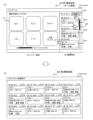
- FIG. 3 is a diagram showing an example of the home screen 100 displayed on the display section 41a of the touch panel display 41 of the operation panel 40 according to the embodiment.
- Home screen 100 is an example of a first history screen.
- the home screen 100 is, for example, a screen that is displayed when the user starts using the image processing device 1. From another perspective, the home screen 100 is displayed when the image processing device 1 is powered on, when the image processing device 1 returns from sleep mode, and/or when the user authentication in the image processing device 1 is successful. , is the screen that will be launched.
- a menu area 110 and a history area 120 are displayed side by side.
- the menu area 110 and the history area 120 are configured by dividing the home screen 100 into two left and right.
- the menu area 110 may be referred to as a main display area.
- History area 120 may be referred to as a timeline area.
- each history button displayed in the history area 120 is a history button 121 (121a to 121c) that individually displays information on completed image processing for each image process. That is, each history button 121 is associated with completed image processing (specifically, completed image processing job).
- the information displayed on the button may be text or a symbol image.
- the button does not have to imitate a physical button.
- a button may be indicated only by text and/or a symbol image and may not have a border surrounding the text and/or symbol image.
- the boundary between the area that accepts the user's operation and the surrounding area does not need to be expressed by a frame line or a difference in color.
- the menu area 110 has a plurality of function buttons 111 corresponding to the type of image processing (in the example of FIG. 3, "copy”, “print”, “scan”, “FAX”, "mail”, and “document box”). (111a, 111b,). Menu area 110 may be scrollable by scroll bar 112. Although an example is shown in which the scrolling direction is the left-right direction, the scrolling direction may be the up-down direction.
- the number of function buttons 111 and the types of functions corresponding to the function buttons 111 may be set as appropriate.
- the function button 111 may be referred to by the text displayed within the function button 111.
- examples of the function buttons 111 include a copy button 111a, a print button 111b, a scan button 111c, a FAX button 111d, a mail button 111e, and a document box button 111f.
- the control unit 50 controls the screen displayed on the display unit 41a to perform an operation related to the function corresponding to the function button 111.
- the display unit 41a is controlled to switch to the screen shown in FIG.
- the control unit 50 switches from the home screen 100 to the copy screen 130 shown in FIG. 4.
- the control unit 50 controls the image processing unit 3 to execute copying.
- the control unit 50 controls the display unit 41a to switch from the copy screen 130 to the home screen 100.
- control unit 50 may control the image processing unit 3 to perform image processing (for example, copying) when the function button 111 is tapped.
- Image processing conditions for example, copy settings
- the history area 120 shown in FIG. 3 is a display area that shows the history of image processing performed in the past.
- the position, shape, and area of the history area 120 are arbitrary.
- the history area 120 is located on one horizontal side (the right side in the illustrated example) of the rectangular home screen 100 whose longitudinal direction is the horizontal direction, and whose longitudinal direction is the vertical direction. It is said to have a rectangular shape.
- the width of the history area 120 is less than 1/2 or less than 1/3 of the width of the home screen 100.
- most of the home screen 100 (for example, 80% or more) excluding the history area 120 is a menu area 110.
- History area 120 may be scrollable by scroll bar 122. Although an example is shown in which the scrolling direction is the up-down direction, the scrolling direction may be the left-right direction.
- the maximum number of history buttons 121 that can be displayed by scrolling in the history area 120 is predetermined. For example, in the history area 120, history buttons 121 for the most recent n jobs (n ⁇ 2) among completed image processing jobs can be displayed by scrolling. In the example of FIG. 3, the number of history buttons 121 that can be displayed at one time in the history area 120 is three. However, the number of history buttons 121 that can be displayed at one time in the history area 120 may be two or four.
- the plurality of history buttons 121 are arranged in a line in a predetermined direction in the order of date and time when the image processing corresponding to the history button 121 was executed (that is, in chronological order). .
- the plurality of history buttons 121 can be arranged in any direction.
- the plurality of history buttons 121 may be arranged from one side to the other in the arrangement direction (from top to bottom in the illustrated example), in chronological order (as in the illustrated example), or in chronological order, or in chronological order.
- By performing a predetermined operation on the operation panel 40 it may be possible to switch between the newest order and the oldest order. Note that in the description of this embodiment, for convenience, it is assumed that the items are arranged in chronological order.
- the history button 121a corresponding to the newest completed image processing is arranged at the top
- the history button 121n corresponding to the n-th job which is the oldest completed image processing, is arranged at the bottom. .
- the control unit 50 When image processing is executed via an operation on the function button 111 or an operation on the history button 121, the control unit 50 adds a new history button 121 related to the image processing. If the image processing on which the history button 121 was added is the same as the new image processing performed via the operation on the history button 121, even if the history button 121 is newly added. Alternatively, only the execution date and time of the image processing corresponding to the operated history button 121 may be updated (from another point of view, the display position of the history button 121 may be changed). Here, the image processing being the same may mean, for example, being the same except for the execution date and time. Note that, unlike the description of this embodiment, the history button 121 does not need to be added for image processing executed via an operation on the history button 121.
- the type of image processing for which the history button 121 is generated is arbitrary. For example, even if the image processing device 1 has the six functions illustrated in the menu area 110, the history button 121 does not need to be generated for all of them.
- the history button 121 may be generated only for image processing in which printing is performed by the image processing apparatus 1, such as "copy” and “print” (and printing in a "box”). Further, for example, the history button 121 may be generated only for image processing in which scanning is performed by the image processing apparatus 1, such as “copy”, “scan”, “FAX”, and "email”. Further, for example, the history button 121 may be generated only for image processing in which no communication is performed, such as "copy,” “print,” and “scan” (and printing in a "box”).
- the history button 121 may or may not be added for image processing performed by transmitting a signal including a print job or the like from another device (for example, a PC) to the communication unit 30. If added, for example, when a user who sent a print job from a PC to the image processing device 1 confirms a printing failure in front of the image processing device 1, the user can reprint via the history button 121. can.
- the number of history buttons 121 (including those displayed by scrolling) that can be displayed in the history area 120 is limited to a predetermined upper limit value (n) or less. Therefore, history buttons 121 are added, and after the number of history buttons 121 reaches the upper limit, when a new history button 121 is added, the oldest history button 121 is deleted. In other words, the oldest history button 121 cannot be displayed.
- the specific value of the upper limit value (n) is arbitrary, and is, for example, 5, 10, or 20.
- the upper limit value may be set by the manufacturer of the image processing device 1 and cannot be changed by the administrator or user of the image processing device 1, or may be settable by the administrator of the image processing device 1. Good too. In an embodiment in which the display mode of the history area 120 can be made different for each user, the upper limit value may be settable by the user.
- Each history button 121 includes (shows) information on the corresponding image processing.
- the information includes, for example, the date and time when the image processing was performed, the type of image processing, the conditions (setting contents) of the image processing, and the name of the user who performed the image processing.
- Other examples include communication destinations (transmission destinations and/or reception destinations) in the FAX function and/or mail function. That is, each history button 121 displays the type of completed image processing, the setting contents of the completed image processing, the processing date and time of the completed image processing, the user name corresponding to the completed image processing, and the information of the completed image processing. Information on at least one of the transmission destinations is shown. This makes it easy for the user to specify the corresponding completed image processing based on the information indicated by each history button 121.
- the type of image processing information included in the history buttons 121 may be the same or different between the history buttons 121.
- the type of information displayed on the history button 121 may differ depending on the type of image processing. More specifically, the history button 121 whose image processing type is copy does not have an item for displaying the communication destination, while the history button 121 whose image processing type is fax or email does not have an item for displaying the communication destination. It may also have an item for displaying the destination.
- FIG. 5 is a diagram showing an example of a screen display when the history area 120 (history button) is operated according to the embodiment. In the example of FIG. 5, it is assumed that the history button 121b regarding FAX executed in the past has been operated.
- the history usage screen 210 shown in FIG. 5 is a screen for setting the conditions to be applied this time, with the past image processing conditions (setting contents) corresponding to the operated history button as initial values.
- the history usage screen 210 allows the user to reuse past settings and smoothly and quickly set the settings to be applied this time.
- Such a display operation of the history usage screen 210 is a general display operation when the history area 120 is used.
- the history usage screen 210 maintains the history area 120 and uses the area corresponding to the menu area 110 on the home screen 100 as the history usage area 150.
- the history usage area 150 includes, for example, a plurality of setting buttons 211 (211a, 211b, . . . ) for setting setting contents (here, FAX conditions), and an execution button 212 for instructing execution of FAX. , and a return button 213 for returning to the home screen 100.
- the setting button 211 displays information indicating the type of setting item corresponding to itself. Furthermore, the setting button 211 may display information indicating the setting state of the item corresponding to itself. In the illustrated example, the type of setting item is shown above the setting button 211, and the current setting state of the item is shown below the setting button 211.
- the number and types of setting buttons 211 are arbitrary.
- the setting buttons 211 include a destination button 211a, a one-sided/double-sided button 211b, a density button 211c, and a group of destination designation buttons 211d. Since these are common, explanations will be omitted.
- the destination button 211a, the one-sided/double-sided button 211b, and the density button 211c display conditions for previously executed faxes as initial values. If these initial values are used as they are, by operating (tapping) the execution button 212, the user can smoothly and quickly perform a fax under the same conditions as those used for previously executed faxes.
- the control unit 50 controls the image processing unit 3 to execute the FAX under partially changed conditions. Note that when the button for returning to the home screen 100 is tapped, or when a certain period of time has elapsed, the control unit 50 controls the display unit 41a to switch to the home screen 100. Further, the layout of the various parts described above is arbitrary, and FIG. 5 is only an example.
- the initial setting may be the setting when the image processing corresponding to the history button 121 was performed.
- the settings when the image processing corresponding to the history button 121 was performed may be set as initial settings.
- configurable items for example, processing conditions
- the number and type of setting buttons 211 in other words, setting items displayed on the history usage screen 210 may change. .
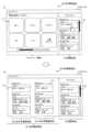
- FIG. 6 is a diagram illustrating an example of an operation for expanding the history area 120 according to the embodiment.
- the display unit 41a includes a menu area 110 in which function buttons 111 corresponding to a plurality of functions are arranged, and a history area 120 in which history buttons 121 corresponding to completed image processing are arranged.
- a first history screen (home screen) 100 is displayed in which , and are arranged.
- the control unit 50 controls the display unit 41a to switch from the first history screen 100 shown in FIG. 6(a) to the second history screen 200 shown in FIG. 6(b) in response to a user operation on the operation panel 40. do.
- the history area 120 is expanded. Thereby, it becomes possible to expand the history area 120 according to user operations, and it is possible to improve convenience for the user who uses the history button 121.
- the second history screen 200 is a screen that does not include the menu area 110 but includes an expanded history area 120.
- the second history screen 200 is a history screen in which the history area 120 is displayed on the entire screen.
- the history buttons 121 can be arranged over the entire screen, and more history buttons 121 can be displayed.
- the operation of switching from the second history screen 200 to the first history screen 100 is performed by pressing the "home button (back button)" (not shown) included in the second history screen 200. It may be an operation.
- the number of history buttons 121 displayed on the second history screen 200 is greater than the number of history buttons 121 displayed on the first history screen 100 shown in FIG. 6(a). .
- the number of history buttons 121 displayed on the first history screen 100 shown in FIG. 6(a) is three
- the number of history buttons 121 displayed on the second history screen 200 shown in FIG. 6(b) is three.
- the number of is 12.
- the desired history button 121 does not exist among the three history buttons 121a to 121c that are initially displayed, the user scrolls the history area 120 to search for the desired history button 121. There is a need to.
- since more history buttons 121 are displayed on the second history screen 200 it becomes easier to search for a desired history button 121.
- the history buttons 121 for up to the most recent 12 jobs among the completed image processing jobs can be displayed at once (that is, they can be displayed without scrolling).
- a scroll bar may be provided on the second history screen 200 so that history buttons 121 corresponding to completed image processing older than the most recent 12 jobs can be displayed by scrolling.
- the history buttons 121a to 121l are divided into a row of history buttons 121a to 121c, a row of history buttons 121d to 121f, a row of history buttons 121g to 121i, and a row of history buttons 121a to 121c. It includes a total of four columns: 121j to 121l.
- each column the items are arranged in chronological order from top to bottom. That is, the history buttons 121 are arranged from top to bottom in chronological order, with line breaks to the right.
- the chronological order can be the same as that of the first history screen 100, and the user's operability can be improved.
- the second history screen 200 may be arranged such that the history buttons 121 are arranged from left to right in chronological order, with line breaks in the downward direction.
- the size of the history button 121 on the second history screen 200 is equal to the size of the history button 121 on the first history screen 100. Thereby, the same operational feeling of the history button 121 as in the first history screen 100 can be maintained on the second history screen 200 as well. However, the size of the history button 121 on the second history screen 200 may be larger than the size of the history button 121 on the first history screen 100.
- the amount of information displayed on the history button 121 on the second history screen 200 may be greater than the amount of information displayed on the history button 121 on the first history screen 100.
- the history button 121 on the second history screen 200 includes (shows) more information on the corresponding image processing than the first history screen 100.
- the history button 121a on the first history screen 100 displays "Copy” as the type of completed image processing, "Color 100% A4" as the setting content of the completed image processing, and "Color 100% A4" as the setting content of the completed image processing. "08/20 9:15" is included as the processing date and time.
- the history button 121a of the second history screen 200 may further include more detailed setting contents, such as "density" and/or "page aggregation" in addition to this information.
- the history button 121a of the second history screen 200 may further include the user name corresponding to the completed image processing. In this way, by increasing the amount of information displayed by the history button 121 on the second history screen 200, it becomes easier for the user to search for the desired history button 121.
- the second history screen 200 may include a group history button, which is the history button 121, associated with a group in which a plurality of completed image processes are classified according to classification conditions.
- the classification condition may be the time of image processing (eg, date and time) or the type of image processing (ie, function).
- the control unit 50 may expand and display the history buttons 121 of each completed image processing corresponding to the selected group history button. Providing such a group history button makes it easy for the user to search for a desired history button 121.
- the first history screen 100 includes a dedicated button 123 for switching from the first history screen 100 to the second history screen 200.
- the control unit 50 controls the display unit 41a to switch from the first history screen 100 to the second history screen 200 in response to the operation unit 41b receiving a user operation to select the dedicated button 123.
- the dedicated button 123 is arranged in the history area 120 (specifically, at the top of the history area 120) of the first history screen 100, and the text "Extended Display" is attached.
- the dedicated button 123 does not need to have any text attached to it.
- the dedicated button 123 may be attached with a symbol image indicating full screen display.
- ⁇ Trigger pattern (2) from the first history screen 100 to the second history screen 200
- the control unit 50 controls the The display section 41a is controlled to switch from the first history screen 100 to the second history screen 200. That is, when any history button 121 in the first history screen 100 is operated, the control unit 50 switches from the first history screen 100 to the second history screen 200. Thereby, the dedicated button 123 like pattern (1) can be made unnecessary.
- the control unit 50 controls the display unit 41a to switch from the first history screen 100 to the second history screen 200 in response to the operation unit 41b accepting a scroll operation on the history area 120 of the first history screen 100. You can. Thereby, it is possible to appropriately switch from the first history screen 100 to the second history screen 200 under a situation where the user is searching for a desired history button 121.
- the control unit 50 upon receiving an operation (slide operation, drag operation) to move the boundary between the menu area 110 and the history area 120 from the history area 120 side to the menu area 110 side on the first history screen 100, the control unit 50 Accordingly, the display section 41a is controlled to switch from the first history screen 100 to the second history screen 200. In that case, if the operation for moving the boundary is completed before reaching the left edge of the screen, the control unit 50 may fix the boundary at the time of completion. As a result, in the second history screen 200, the history area 120 may be expanded while the menu area 110 may be displayed in a reduced state.
- FIG. 7 is a diagram showing an example of a control flow of the image processing device 1 according to the embodiment.
- one of the history buttons 121 is operated by the user.
- step S1 the control unit 50 displays a menu area 110 in which function buttons 111 corresponding to the type of image processing (i.e., multiple functions of the image processing apparatus 1) are arranged, and history buttons corresponding to completed image processing.
- the display unit 41a is controlled to display the first history screen 100 in which the arranged history areas 120 are arranged.
- step S2 the control unit 50 determines whether the operation unit 41b has received a user operation to switch from the first history screen 100 to the second history screen 200.
- the user operation is, for example, one of the trigger patterns (1) to (3) described above. If it is determined that the user operation has been accepted (step S2: YES), the control unit 50 advances the process to step S3. On the other hand, if it is determined that the user operation has not been accepted (step S2: NO), the control unit 50 advances the process to step S4.
- step S3 the control unit 50 controls the display unit 41a to switch from the first history screen 100 to the second history screen 200 in which the history area 120 is expanded.
- step S4 the operation unit 41b accepts a user operation on any of the history buttons 121.
- step S5 the control unit 50 determines whether the user operation received in step S4 is a predetermined user operation.
- the predetermined user operation is a long press operation of the history button 121 or a continuous press operation (eg, double tap) of the history button 121. If it is determined that the user operation received in step S4 is a predetermined user operation (step S5: YES), the control unit 50 skips steps S6 and S7 and advances the process to step S8. On the other hand, if it is determined that the user operation received in step S4 is not the predetermined user operation (step S5: NO), the control unit 50 advances the process to step S6.
- the control unit 50 when the operation unit 41b receives a predetermined user operation on the history button 121, the control unit 50 separately receives an execution instruction from the user to instruct the execution of image processing corresponding to the history button 121. Even if it is not accepted, the image processing is executed using a predetermined user operation as a trigger. This makes it possible to use the history button 121 to cause the image processing apparatus 1 to execute image processing more quickly.
- step S6 the control unit 50 uses the history usage screen 210 (see FIG.
- the display unit 41a is controlled to display (see 5).
- step S7 while the history usage screen 210 is displayed, the operation unit 41b receives an execution instruction (that is, an operation on the execution button) to instruct the execution of image processing from the user.
- an execution instruction that is, an operation on the execution button
- step S8 the control unit 50 controls the image processing unit 3 to execute the instructed image processing.
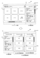
- FIG. 8 is a diagram for explaining this modification example.
- the second history screen 200 is a screen that does not include the menu area 110 but includes an expanded history area 120.
- the second history screen 200 is displayed in response to the above-mentioned trigger pattern (2), that is, the operation unit 41b receives a user operation to select the history button 121 in the first history screen 100.
- the second history screen 200 includes a history area 120 and an additional history area 125 added by expanding the history area 120.
- the position of the history area 120 is maintained, and the additional history area 125 is arranged at a position corresponding to the position of the menu area 110 on the first history screen 100. That is, the area corresponding to the menu area 110 of the first history screen 100 is used as the additional history area 125 of the second history screen 200, and the history area 120 is arranged in the same manner as the first history screen 100. Thereby, the area corresponding to the menu area 110 can be effectively utilized for displaying history information.
- the additional history area 125 of the second history screen 200 shown in FIG. 8(b) includes a plurality of condition-specific history areas 126, each associated with a classification condition.
- history buttons 121 corresponding to completed image processing that match the corresponding classification condition are arranged.
- the plurality of condition-specific history areas 126 two condition-specific history areas 126a and 126b each configured in the vertical direction are illustrated.
- the second history screen 200 may include two or more condition-based history areas 126. This allows the history buttons 121 to be displayed according to classification conditions, making it easier for the user to search for the desired history button 121.
- the additional history area 125 or each condition-specific history area 126 may be scrollable in the vertical direction.
- the plurality of condition-specific history areas 126 are a plurality of function-specific history areas corresponding to a plurality of functions (image processing types) of the image processing device 1, a plurality of date-specific history areas corresponding to a plurality of dates, or a plurality of date-specific history areas corresponding to a plurality of dates. These are a plurality of period-specific history areas corresponding to a plurality of periods with different values.
- the plurality of condition-specific history areas 126 are a plurality of date-specific history areas corresponding to a plurality of dates. This makes it easy for the user to search for the desired history button 121 by date.
- the condition-specific history area 126a includes a history button 121 for each completed image process that belongs to the current date, and includes a history button 121 for each completed image process that belongs to a specific date in the past than the current day. .
- FIG. 9 is a diagram for explaining this modification example.
- the second history screen 200 includes a history area 120 and an additional history area 125 added by expanding the history area 120.
- the history area 120 is moved to a position corresponding to the position of the menu area 110 of the first history screen 100, and the additional history area 125 is moved to the position of the history area 120 of the first history screen 100. is placed at the position corresponding to.
- the history area 120 that was placed on the right side of the first history screen 100 is placed on the left side of the second history screen 200.
- the additional history area 125 is arranged to cover the right end position.
- trigger patterns (1) and (2) when switching to the second history screen 200 in response to a user operation on the history area 120 of the first history screen 100, the user's line of sight and finger are placed on the right side of the screen. It is thought that it is directed towards. Therefore, by arranging the additional history area 125 so as to cover the right end position, the user can easily operate the history button 121 in the additional history area 125. Note that this arrangement method (layout) of the additional history area 125 is also applicable to the first modification example described above and the modification example described later. However, similarly to the first modification example described above, in the second history screen 200, the position of the history area 120 is maintained, and the additional history area 125 is located at a position corresponding to the position of the menu area 110 on the first history screen 100. may be placed in
- the additional history area 125 of the second history screen 200 shown in FIG. 9 includes a plurality of condition-based history areas 126, each associated with a classification condition.
- history buttons 121 corresponding to completed image processing that match the corresponding classification condition are arranged.
- the plurality of condition-specific history areas 126 two condition-specific history areas 126a and 126b each configured in the vertical direction are illustrated. Further, each condition-specific history area 126 is configured to be scrollable in the vertical direction.
- the plurality of condition-specific history areas 126 are a plurality of period-specific history areas corresponding to a plurality of periods each having a different time length.
- the condition-specific history area 126a is a date-specific history area
- the condition-specific history area 126b is a weekly history area. If the screen size allows, you may add a monthly history area.
- Group history buttons, which are history buttons 121, are arranged in each condition-based history area 126, which are history buttons 121 associated with groups into which a plurality of completed image processes are classified according to classification conditions.
- the control unit 50 causes the display unit to expand and display the history buttons of each completed image processing belonging to the group corresponding to the operated group history button. 41a.
- a plurality of history buttons 121a by date are arranged in the history region 126a by condition
- a plurality of history buttons 121a by week are arranged in the history region 126b by condition.
- the control unit 50 causes the display unit to expand and display the history buttons of each completed image processing that belong to the date corresponding to the operated history button 121a. 41a.
- the control unit 50 expands and displays the history buttons of each completed image processing belonging to the week corresponding to the operated history button 121a. Controls the display section 41a.
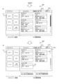
- FIG. 10 is a diagram for explaining an example of a trigger for switching to the second history screen 200 according to this modification example.
- the first history screen 100 includes a dedicated button 123 for switching from the first history screen 100 to the second history screen 200.
- the control unit 50 causes the display unit to switch from the first history screen 100 to the second history screen 200 shown in FIG. 41a.
- the dedicated button 123 is arranged at the top of the history area 120 of the first history screen 100, and a symbol image indicating full-screen display is attached.
- a dedicated button 113 for displaying the menu area 110 in full screen is arranged in the menu area 110 of the first history screen 100.
- the control unit 50 controls the display unit to display the menu area 110 in full screen, that is, to display a home screen that does not include the history area 120. 41a. In the menu area 110 expanded in this way, more function buttons 111 can be displayed.
- FIG. 11 is a diagram for explaining this modification example.
- the reduced menu area 110 is on the left side
- the expanded history area 120 is on the right side.
- the control unit 50 switches to the layout shown in FIG. 11(c).
- the control unit 50 displays the first history screen 100 shown in FIG. 11(a). Switch.
- the reduced menu area 110 is on the right side, and the expanded history area 120 is on the left side.
- the control unit 50 switches to the layout shown in FIG. 11(b).
- the control unit 50 displays the first history screen 100 shown in FIG. 11(a). Switch.
- the first history screen 100 shown in FIG. 11(a) has a dedicated button 123a for switching to the layout of the second history screen 200 shown in FIG. 11(b), and the second history screen 200 shown in FIG. 11(c).
- a dedicated button 123b for switching to a layout is included.
- the control unit 50 switches to the layout shown in FIG. 11(b).
- the control unit 50 switches to the layout shown in FIG. 11(c).
- control unit 50 switches from the second history screen 200 to the first history screen 100 in response to the operation unit 41b receiving a user operation to select the reduced menu area 110.
- the display unit 41a may also be controlled.
- the history area 120 of the second history screen 200 may be provided with a condition-based history area 126.
- FIG. 12 is a diagram for explaining this modification example.
- the control unit 50 in response to the operation unit 41b receiving a user operation specifying a classification condition, the control unit 50 causes the display unit 41a to display a plurality of condition-specific history areas 126 according to the specified classification condition. control. For example, in response to the operation unit 41b receiving a user operation to select the "arrange by function" button 127a on the second history screen 200 shown in FIG. As shown in FIG. 3, the display unit 41a is controlled to display the condition-specific history area 126 classified according to function. Note that when the operation unit 41b receives a user operation to select the “return” button 127b arranged in the history area 120 shown in FIG. 12(a), the control unit 50 switches to the first history screen 100.
- a plurality of condition-specific history areas 126 provided in the history area 120 are a plurality of function-specific history areas corresponding to a plurality of functions of the image processing device 1.
- history buttons 121 for completed image processing that match the "copy” function are arranged in chronological order from top to bottom.
- history buttons 121 for completed image processing that match the "FAX" function are arranged in chronological order from top to bottom.
- the control unit 50 changes the history of the condition-specific history area 126 for a function different from "copy” and "FAX".
- the display section 41a is controlled to display in the area 120.
- the display section 41a is controlled to display the condition-specific history area 126. Note that when the operation unit 41b receives a user operation to select the “return” button 127d arranged in the history area 120 shown in FIG. 12(b), the control unit 50 switches to the first history screen 100.
- the history usage screen 210 may be regarded as a type of the second history screen 200. Further, the history usage area 150 on the history usage screen 210 may be regarded as a part of the expanded history area 120, specifically, the additional history area 125 added by expanding the history area 120. In that case, as shown in FIG. 13, on the history usage screen 210 (second history screen 200), the history area 120 is moved to a position corresponding to the position of the menu area 110 on the first history screen 100, and The usage area 150 (additional history area 125) may be arranged at a position corresponding to the position of the history area 120 on the first history screen 100.
- the history area 120 that was placed on the right side of the first history screen 100 is placed on the left side of the history usage screen 210.
- the history usage area 150 (additional history area 125) is arranged to cover the right end position.
- a program may be provided that causes the image processing device 1 to execute the operations according to the embodiments described above.
- the program may be recorded on a computer readable medium.
- the computer-readable medium on which the program is recorded may be a non-transitory recording medium.
- the non-transitory recording medium is not particularly limited, and may be, for example, a recording medium such as a CD-ROM or a DVD-ROM.
- the circuits that execute each process performed by the image processing device 1 may be integrated, and at least a portion of the image processing device 1 may be configured as a semiconductor integrated circuit (chip set, SoC).
- the words “based on” and “in accordance with” do not mean “based solely on” or “in accordance with” unless expressly stated otherwise.
- Reference to “based on” means both “based solely on” and “based at least in part on.”
- the phrase “in accordance with” means both “in accordance with” and “in accordance with, at least in part.”
- the terms “include”, “comprise”, and variations thereof do not mean to include only the listed items, and may include only the listed items, or may include only the listed items. In addition, it means that further items may be included.
- the term “or” is not intended to be exclusive OR. Furthermore, any reference to elements using the designations "first,” “second,” etc.
- An image processing device 1 that executes a plurality of functions related to image processing, A first history screen 100 is displayed in which a menu area 110 in which function buttons 111 corresponding to the plurality of functions are arranged and a history area 120 in which history buttons 121 corresponding to completed image processing are arranged are arranged.
- An operation panel 40 having a display section 41a; a control unit 50 that controls the display unit 41a to switch from the first history screen 100 to a second history screen 200 in which the history area 120 is expanded in accordance with a user operation on the operation panel 40; Image processing device 1.
- the amount of information displayed on the history button 121 on the second history screen 200 is larger than the amount of information displayed on the history button 121 on the first history screen 100. image processing device 1.
- the second history screen 200 includes group history buttons 121a/121b, which are the history buttons 121 associated with groups in which a plurality of completed image processes are classified according to classification conditions. Image processing device 1 as described.
- the first history screen 100 includes a dedicated button 123 for switching from the first history screen 100 to the second history screen 200,
- the control unit 50 controls the display unit 41a to switch from the first history screen 100 to the second history screen 200 in response to receiving a user operation to select the dedicated button 123. 5.
- Image processing device 1 according to any one of 5.
- Appendix 7 The image processing device 1 according to appendix 6, wherein the dedicated button 123 is arranged in the history area 120 of the first history screen 100.
- the control unit 50 controls the display to switch from the first history screen 100 to the second history screen 200 in response to receiving a user operation of selecting the history button 121 in the first history screen 100.
- the image processing device 1 according to any one of Supplementary Notes 1 to 5, which controls the unit 41a.
- the control unit 50 switches from the first history screen 100 to the second history screen 200 in response to receiving an operation on the boundary between the menu area 110 and the history area 120 on the first history screen 100.
- the image processing device 1 according to any one of Supplementary Notes 1 to 5, wherein the display unit 41a is controlled to switch.
- control unit 50 When the control unit 50 receives a predetermined user operation on the history button 121, the control unit 50 triggers the predetermined user operation even if it does not separately receive an execution instruction from the user to instruct the execution of image processing corresponding to the history button 121.
- the image processing device 1 according to any one of Supplementary Notes 1 to 10, which performs the image processing as follows.
- Appendix 12 The image processing device 1 according to appendix 11, wherein the predetermined user operation is a long press operation of the history button 121 or a continuous press operation of the history button 121.
- the second history screen 200 includes the history area 120 and an additional history area 125 added by expanding the history area 120, In the second history screen 200, the position of the history area 120 is maintained, and the additional history area 125 is arranged at a position corresponding to the position of the menu area 110 on the first history screen 100. 12. Image processing device 1 according to any one of 12.
- the second history screen 200 includes the history area 120 and an additional history area 125 added by expanding the history area 120, In the second history screen 200, the history area 120 is moved to a position corresponding to the position of the menu area 110 on the first history screen 100, and the additional history area 125 is moved to a position corresponding to the position of the menu area 110 on the first history screen 100.
- the image processing device 1 according to supplementary note 14, wherein the image processing device 1 is arranged at a position corresponding to the position of the history area 120.
- the second history screen 200 is a screen that includes the expanded history area 120 and the menu area 110 that has been reduced due to the expansion of the history area 120.
- Image processing device 1 The second history screen 200 is a screen that includes the expanded history area 120 and the menu area 110 that has been reduced due to the expansion of the history area 120.
- the control unit 50 controls the display unit 41a to switch from the second history screen 200 to the first history screen 100 in response to receiving a user operation to select the reduced menu area 110.
- Image processing device 1 according to appendix 16.
- the second history screen 200 includes dedicated buttons 124a/124c for switching the positional relationship between the reduced menu area 110 and the expanded history area 120,
- the control unit 50 adjusts the positions of the reduced menu area 110 and the expanded history area 120 in response to receiving a user operation to select the dedicated button 124a/124c on the second history screen 200.
- the image processing device 1 according to supplementary note 16 or 17, wherein the display unit 41a is controlled to change the relationship.
- the second history screen 200 includes a plurality of condition-specific history areas 126 each associated with a classification condition, The image processing device 1 according to any one of Supplementary Notes 1 to 18, wherein history buttons 121 corresponding to completed image processing that match the corresponding classification conditions are arranged in each of the plurality of condition-specific history areas 126.
- the plurality of condition-specific history areas 126 may include a plurality of function-specific history areas corresponding to the plurality of functions, a plurality of date-specific history areas corresponding to a plurality of dates, or a plurality of condition-specific history areas corresponding to a plurality of periods each having a different time length.
- control unit 50 controls the display unit 41a to display the plurality of condition-specific history areas 126 according to the specified classification condition.
- Image processing device 1 according to item 19 or 20.
- a control method for controlling an image processing device 1 that executes a plurality of functions related to image processing comprising: A first history screen 100 in which a menu area 110 in which function buttons 111 corresponding to the plurality of functions are arranged and a history area 120 in which history buttons 121 corresponding to completed image processing are arranged are displayed on the operation panel. 40 steps, A control method comprising the step of switching from the first history screen 100 to a second history screen 200 in which the history area 120 is expanded according to a user operation on the operation panel 40.
- An image processing device 1 that executes multiple functions related to image processing, A first history screen 100 in which a menu area 110 in which function buttons 111 corresponding to the plurality of functions are arranged and a history area 120 in which history buttons 121 corresponding to completed image processing are arranged are displayed on the operation panel. 40 steps, A program that executes a step of switching from the first history screen 100 to a second history screen 200 in which the history area 120 is expanded in response to a user operation on the operation panel 40.
- Image processing device 3 Image processing section 5: Bus 10: Printer 20: Scanner 30: Communication section 40: Operation panel 41: Touch panel display 41a: Display section 41b: Operation section 41c: Physical button 50: Control section 60: Memory Section 71: Paper feed tray 72: Paper output tray 73: Original table
Abstract
This image processing device, which performs a plurality of functions for image processing, is provided with: an operation panel including a display unit that displays a first history screen having arranged therein a menu area in which function buttons corresponding to the plurality of functions are arrayed and a history area in which history buttons corresponding to completed image processing are arrayed; and a control unit that, in response to a user operation on the operation panel, controls the display unit to switch from the first history screen to a second history screen having an expanded history area.
Description
本開示は、画像処理装置、制御方法、及びプログラムに関する。
The present disclosure relates to an image processing device, a control method, and a program.
特許文献1には、画像処理の種別に対応した機能ボタンが配列されたメニュー領域と、過去に完了した画像処理(以下、「完了済み画像処理」と称する)に対応した履歴ボタンが配列された履歴領域とを並べて表示する操作パネルを有する画像処理装置が記載されている。このような画像処理装置は、履歴ボタンを選択するユーザ操作を受け付けたことに応じて、当該履歴ボタンに対応する画像処理の設定内容が再現されるため、ユーザが設定内容を入力する手間を省くことができる。
Patent Document 1 discloses a menu area in which function buttons corresponding to the type of image processing are arranged, and history buttons corresponding to image processing completed in the past (hereinafter referred to as "completed image processing") are arranged. An image processing apparatus is described that has an operation panel that displays history areas side by side. In such an image processing device, in response to receiving a user operation to select a history button, the image processing settings corresponding to the history button are reproduced, thereby saving the user the trouble of inputting the settings. be able to.
上述のような画像処理装置は、履歴ボタンを利用するユーザの利便性をさらに高める点で改善の余地がある。
The image processing device as described above has room for improvement in terms of further increasing the convenience for users who use the history button.
本開示は、ユーザの利便性をさらに高めることが可能な画像処理装置、制御方法、及びプログラムを提供する。
The present disclosure provides an image processing device, a control method, and a program that can further improve user convenience.
本開示の第1の態様に係る画像処理装置は、画像処理に関する複数の機能を実行する画像処理装置であって、前記複数の機能に対応した機能ボタンが配列されたメニュー領域と、完了済み画像処理に対応した履歴ボタンが配列された履歴領域と、が並べられた第1履歴画面を表示する表示部を有する操作パネルと、前記操作パネルに対するユーザ操作に応じて、前記第1履歴画面から、前記履歴領域が拡張された第2履歴画面へ切り替えるように前記表示部を制御する制御部と、を備える。
An image processing device according to a first aspect of the present disclosure is an image processing device that executes a plurality of functions related to image processing, and includes a menu area in which function buttons corresponding to the plurality of functions are arranged, and a completed image. an operation panel having a display section that displays a history area in which history buttons corresponding to processes are arranged; and a first history screen in which history buttons are arranged; and in response to a user operation on the operation panel, from the first history screen, and a control unit that controls the display unit to switch to a second history screen in which the history area is expanded.
本開示の第2の態様に係る制御方法は、画像処理に関する複数の機能を実行する画像処理装置を制御する制御方法であって、前記複数の機能に対応した機能ボタンが配列されたメニュー領域と、完了済み画像処理に対応した履歴ボタンが配列された履歴領域と、が並べられた第1履歴画面を操作パネルで表示するステップと、前記操作パネルに対するユーザ操作に応じて、前記第1履歴画面から、前記履歴領域が拡張された第2履歴画面へ切り替えるステップと、を有する。
A control method according to a second aspect of the present disclosure is a control method for controlling an image processing apparatus that executes a plurality of functions related to image processing, the control method comprising: a menu area in which function buttons corresponding to the plurality of functions are arranged; , a history area in which history buttons corresponding to completed image processing are arranged, and displaying on an operation panel a first history screen in which history buttons corresponding to completed image processing are arranged; and switching to a second history screen in which the history area is expanded.
本開示の第3の態様に係るプログラムは、画像処理に関する複数の機能を実行する画像処理装置に、前記複数の機能に対応した機能ボタンが配列されたメニュー領域と、完了済み画像処理に対応した履歴ボタンが配列された履歴領域と、が並べられた第1履歴画面を操作パネルで表示するステップと、前記操作パネルに対するユーザ操作に応じて、前記第1履歴画面から、前記履歴領域が拡張された第2履歴画面へ切り替えるステップと、を実行させる。
A program according to a third aspect of the present disclosure includes an image processing device that executes a plurality of functions related to image processing, a menu area in which function buttons corresponding to the plurality of functions are arranged, and a menu area corresponding to completed image processing. displaying on an operation panel a history area in which history buttons are arranged; and expanding the history area from the first history screen in response to a user operation on the operation panel. and switching to the second history screen.
図面を参照しながら、実施形態に係る画像処理装置について説明する。図面の記載において、同一又は類似の部分には同一又は類似の符号を付している。
An image processing device according to an embodiment will be described with reference to the drawings. In the description of the drawings, the same or similar parts are designated by the same or similar symbols.
(画像処理装置の構成)
まず、実施形態に係る画像処理装置の構成について説明する。図1は、実施形態に係る画像処理装置1の機能ブロック構成を示す図である。図2は、実施形態に係る画像処理装置1の外観構成例を示す図である。なお、「画像」は、文字のみを含むものであっても構わない。「画像データ」の形式は、種々のものとされてよく、例えば、ベクター形式であってもよいし、ラスター形式であってもよい。実施形態の説明では、便宜上、「画像」と「画像データ」とを厳密に区別しないことがある。「画像データ」は、画像処理が行われる過程において、適宜に形式の変換が行われてよい。 (Configuration of image processing device)
First, the configuration of an image processing apparatus according to an embodiment will be described. FIG. 1 is a diagram showing a functional block configuration of animage processing apparatus 1 according to an embodiment. FIG. 2 is a diagram showing an example of the external configuration of the image processing device 1 according to the embodiment. Note that the "image" may include only characters. The format of the "image data" may be various, for example, it may be a vector format or a raster format. In the description of the embodiments, for convenience, "image" and "image data" may not be strictly distinguished. The format of the "image data" may be converted as appropriate during the process of image processing.
まず、実施形態に係る画像処理装置の構成について説明する。図1は、実施形態に係る画像処理装置1の機能ブロック構成を示す図である。図2は、実施形態に係る画像処理装置1の外観構成例を示す図である。なお、「画像」は、文字のみを含むものであっても構わない。「画像データ」の形式は、種々のものとされてよく、例えば、ベクター形式であってもよいし、ラスター形式であってもよい。実施形態の説明では、便宜上、「画像」と「画像データ」とを厳密に区別しないことがある。「画像データ」は、画像処理が行われる過程において、適宜に形式の変換が行われてよい。 (Configuration of image processing device)
First, the configuration of an image processing apparatus according to an embodiment will be described. FIG. 1 is a diagram showing a functional block configuration of an
図1に示すように、画像処理装置1は、プリンタ10と、スキャナ20と、通信部30と、操作パネル40と、制御部50と、記憶部60とを有する。画像処理装置1は、1種以上の画像処理を行うことが可能な構成を有している。実施形態では、画像処理を行うための構成として、プリンタ10、スキャナ20、及び通信部30が設けられている。プリンタ10、スキャナ20、及び通信部30は、画像処理部3を構成する。但し、画像処理装置1は、プリンタ10及びスキャナ20の一方のみを有する構成であってもよいし、通信部30を有していない構成であってもよい。
As shown in FIG. 1, the image processing device 1 includes a printer 10, a scanner 20, a communication section 30, an operation panel 40, a control section 50, and a storage section 60. The image processing device 1 has a configuration capable of performing one or more types of image processing. In the embodiment, a printer 10, a scanner 20, and a communication section 30 are provided as components for performing image processing. The printer 10, the scanner 20, and the communication section 30 constitute the image processing section 3. However, the image processing device 1 may have a configuration that includes only one of the printer 10 and the scanner 20, or may have a configuration that does not include the communication section 30.
実施形態では、画像処理部3が実行する画像処理の種別には、「プリント」、「コピー」、「スキャン」、及び「ファクシミリ(FAX)」がある。すなわち、画像処理装置1は、「プリント」、「コピー」、「スキャン」、及び「FAX」のそれぞれの機能を有する。
In the embodiment, the types of image processing performed by the image processing unit 3 include "print", "copy", "scan", and "facsimile (FAX)". That is, the image processing device 1 has the respective functions of "print", "copy", "scan", and "FAX".
「コピー」は、スキャナ20で読み取った画像をプリンタ10で用紙に印刷する機能である。「プリント」は、通信部30が外部から受信したデータに基づく画像又は画像処理装置1に接続されている記録媒体(不図示)に記憶されているデータに基づく画像をプリンタ10で印刷する機能である。「スキャン」は、スキャナ20で読み取った画像をデータとして保存する機能である。保存先は、例えば、記憶部60が含む補助記憶装置(別の観点では不揮発性メモリ)、画像処理装置1に接続されている記憶媒体、又は画像処理装置1と通信部30を介して通信を行う他の機器である。「FAX」は、通信部30が電話回線を介して外部から受信したデータをプリンタ10で用紙に印刷する機能及びスキャナ20で読み取った画像データを通信部30が外部へ電話回線を介して送信する機能である。
"Copy" is a function that prints an image read by the scanner 20 onto paper using the printer 10. “Print” is a function that allows the printer 10 to print an image based on data received from the outside by the communication unit 30 or an image based on data stored in a recording medium (not shown) connected to the image processing device 1. be. "Scan" is a function that saves an image read by the scanner 20 as data. The storage destination is, for example, an auxiliary storage device included in the storage section 60 (nonvolatile memory from another point of view), a storage medium connected to the image processing device 1, or a storage device that communicates with the image processing device 1 via the communication section 30. Other equipment to do. "FAX" is a function in which the communication unit 30 prints data received from the outside via a telephone line on paper using the printer 10, and a function in which the communication unit 30 transmits image data read by the scanner 20 to the outside via the telephone line. It is a function.
画像処理部3は、必ずしもこれらの機能のすべてに対応していなくてもよい。画像処理部3は、例えば、プリント、コピー、スキャン、及びFAXのうち1つのみ又は2つのみに対応していてもよい。画像処理部3は、さらに、「メール」機能に対応していてもよい。「メール」は、電子メールに関する設定及び/又は実行を行う機能である。この機能では、例えば、通信部30によって受信されたメールの内容の一部又は全部がプリンタ10によって印刷されてよいし、スキャナ20によって読み取られた画像のデータを通信部30がメールによって送信してもよい。
The image processing unit 3 does not necessarily have to support all of these functions. The image processing unit 3 may be capable of handling only one or two of printing, copying, scanning, and FAX, for example. The image processing unit 3 may further support an "email" function. "Mail" is a function that performs settings and/or execution regarding e-mail. With this function, for example, part or all of the content of an email received by the communication unit 30 may be printed by the printer 10, or the communication unit 30 may transmit data of an image read by the scanner 20 by email. Good too.
プリンタ10は、制御部50の制御下で画像印刷を行う。例えば、プリンタ10は、図2に示す給紙トレイ71に配置された用紙に印刷を行い、印刷後の用紙を排紙トレイ72に排出する。プリンタ10は、1つの給紙トレイ71のみを有していてもよいし、複数の給紙トレイ71を有していてもよい。複数の給紙トレイ71は、例えば、異なるサイズの用紙を収容することができる。別の観点では、プリンタ10は、用紙のサイズを選択する機能を有していてもよい。プリンタ10は、カラー(並びにモノクロ及びグレースケール)の印刷が可能な構成であってもよい。
The printer 10 prints images under the control of the control unit 50. For example, the printer 10 prints on paper placed in a paper feed tray 71 shown in FIG. 2, and discharges the printed paper to a paper discharge tray 72. The printer 10 may have only one paper feed tray 71 or may have multiple paper feed trays 71. For example, the plurality of paper feed trays 71 can accommodate paper of different sizes. From another perspective, the printer 10 may have a function to select the paper size. The printer 10 may be configured to be capable of color (as well as monochrome and grayscale) printing.
スキャナ20は、制御部50の制御下で画像スキャンを行い、画像データを生成する。具体的には、スキャナ20は、図2に示す原稿台73又はADF(Auto Document Feeder)74にセットされた原稿に対して、原稿ガラスに沿って移動する撮像装置による撮像(スキャン)を行い、画像データを生成する。
The scanner 20 performs image scanning under the control of the control unit 50 and generates image data. Specifically, the scanner 20 performs imaging (scanning) of a document set on a document table 73 or an ADF (Auto Document Feeder) 74 shown in FIG. 2 using an imaging device that moves along a document glass. Generate image data.
通信部30は、制御部50の制御下で画像データ通信を行う。具体的には、通信部30は、画像処理装置1と他の機器との通信を実現する。他の機器としては、例えば、パーソナルコンピュータ(PC)、携帯端末(スマートフォン等)、他の画像処理装置及びサーバが挙げられる。サーバとしては、例えば、ファイルサーバ、メールサーバ及びWebサーバが挙げられる。通信は、他の機器と直接的に行われるものであってもよいし、ネットワークを介して間接的に行われるものであってもよい。ネットワークとしては、例えば、電話網、インターネット、プライベートネットワーク及びLAN(Local Area Network)が挙げられる。また、通信は、有線通信であってもよいし、無線通信であってもよい。
The communication unit 30 performs image data communication under the control of the control unit 50. Specifically, the communication unit 30 realizes communication between the image processing device 1 and other devices. Other devices include, for example, personal computers (PCs), mobile terminals (smartphones, etc.), other image processing devices, and servers. Examples of servers include file servers, mail servers, and web servers. Communication may be performed directly with other devices or may be performed indirectly via a network. Examples of the network include a telephone network, the Internet, a private network, and a LAN (Local Area Network). Further, the communication may be wired communication or wireless communication.
操作パネル40は、ユーザ操作(ユーザ入力)を受け付ける操作部を構成する。操作パネル40は、タッチパネルディスプレイ41を有する。図2に示すように、操作パネル40は、1つ又は複数の物理ボタン41cを有していてもよい。タッチパネルディスプレイ41は、制御部50の制御下で画像を表示する表示部41aと、表示部41aに対するユーザ操作(例えば、タッチ操作)を受け付ける操作部41bとを有する。例えば、表示部41aは、液晶ディスプレイ又は有機EL(Electro Luminescence)ディスプレイによって構成される。これらのディスプレイは、規則的に配列された比較的多数の画素を有しており、画像データに基づいて任意の形状を含む画像を表示可能である。表示部41aは、カラー画像を表示可能であってもよい。操作部41bは、表示部41aに対するタッチ操作の位置を検出し、検出結果を制御部50に出力する。操作部41bは、表示部41aに重なるタッチパネルと、タッチパネルの出力をアナログ/デジタル(A/D)変換するA/D変換器とを含んでもよい。実施形態の説明では、便宜上、操作部41bに対する「ユーザ操作」について、「押下」、「タッチ」、「タップ」等の具体的な態様を示す用語を用いることがあるが、これらの用語は、「所定の操作」と上位概念化されてよい。
The operation panel 40 constitutes an operation section that accepts user operations (user inputs). The operation panel 40 has a touch panel display 41. As shown in FIG. 2, the operation panel 40 may have one or more physical buttons 41c. The touch panel display 41 includes a display section 41a that displays images under the control of the control section 50, and an operation section 41b that receives user operations (for example, touch operations) on the display section 41a. For example, the display section 41a is configured by a liquid crystal display or an organic EL (Electro Luminescence) display. These displays have a relatively large number of regularly arranged pixels, and can display images containing arbitrary shapes based on image data. The display section 41a may be capable of displaying a color image. The operation unit 41b detects the position of the touch operation on the display unit 41a, and outputs the detection result to the control unit 50. The operation unit 41b may include a touch panel that overlaps the display unit 41a, and an A/D converter that performs analog/digital (A/D) conversion of the output of the touch panel. In the description of the embodiment, for convenience, terms such as "push", "touch", "tap", etc. that indicate specific aspects of "user operation" on the operation unit 41b are sometimes used, but these terms are It may be conceptualized as a "predetermined operation."
制御部50は、1つ又は複数のプロセッサを含んで構成され、画像処理装置1の全体を制御する。制御部50は、記憶部60に記憶されているプログラムを実行することによって、種々の処理を実行する。制御部50は、プリンタ10、スキャナ20、通信部30、及び操作パネル40の動作を制御する。例えば、制御部50は、操作パネル40を介してユーザからの操作(指示)を受けた場合、操作内容に応じた処理を実行する。操作パネル40は、制御部50からの指示に従い、タッチパネルディスプレイ41上で各種操作画面を表示する。なお、制御部50は、一定の動作のみを行うように構成された論理回路等を含んでいてもよい。
The control unit 50 is configured to include one or more processors, and controls the entire image processing device 1. The control unit 50 executes various processes by executing programs stored in the storage unit 60. The control unit 50 controls the operations of the printer 10, scanner 20, communication unit 30, and operation panel 40. For example, when the control unit 50 receives an operation (instruction) from a user via the operation panel 40, it executes processing according to the content of the operation. The operation panel 40 displays various operation screens on the touch panel display 41 according to instructions from the control unit 50. Note that the control unit 50 may include a logic circuit or the like configured to perform only certain operations.
記憶部60は、例えば、ROM(Read Only Memory)、RAM(Random Access Memory)及び補助記憶装置等の種々のメモリを含んで構成される。なお、制御部50及び記憶部60の組み合わせは、コンピュータとして捉えられてよい。制御部50により実行されるプログラムは、例えば、記憶部60のROM及び/又は補助記憶装置に記憶されている。実施形態では、記憶部60は、画像処理部3による各完了済み画像処理について、当該画像処理が実行された日時と、当該画像処理の種別と、当該画像処理における設定内容と、当該画像処理を行ったユーザの名前(画像処理に対応するユーザ名)とを対応付けた履歴情報を記憶する。記憶部60が記憶する履歴情報は、後述の履歴表示のために用いられる。
The storage unit 60 is configured to include various memories such as a ROM (Read Only Memory), a RAM (Random Access Memory), and an auxiliary storage device. Note that the combination of the control section 50 and the storage section 60 may be regarded as a computer. The program executed by the control unit 50 is stored, for example, in the ROM and/or the auxiliary storage device of the storage unit 60. In the embodiment, the storage unit 60 stores, for each completed image process by the image processing unit 3, the date and time when the image process was executed, the type of image process, the settings for the image process, and the information about the image process. History information is stored that is associated with the name of the user who performed the image processing (user name corresponding to the image processing). The history information stored in the storage unit 60 is used for history display, which will be described later.
プリンタ10、スキャナ20、通信部30、操作パネル40、制御部50、及び記憶部60は、例えば、バス5によって接続されている。図1では、模式的に1本のバス5に全ての構成要素が接続されているが、複数のバスが存在してもよい。例えば、アドレスバス、データバス及びコントロールバスが設けられてよい。
The printer 10, scanner 20, communication section 30, operation panel 40, control section 50, and storage section 60 are connected by a bus 5, for example. In FIG. 1, all the components are schematically connected to one bus 5, but a plurality of buses may exist. For example, an address bus, a data bus and a control bus may be provided.
なお、図2では、画像処理装置1の外観として、業務用の複合機の外観を例示している。しかしながら、画像処理装置1の運用方法は任意である。例えば、画像処理装置1は、家に置かれて、家庭的又は個人的に利用されてもよいし、会社に置かれて、特定かつ複数のユーザに利用されてもよいし、コンビニエンスストア等の店舗に置かれて、不特定多数のユーザに利用されてもよい。
Note that in FIG. 2, the appearance of a business-use multifunction peripheral is illustrated as an example of the appearance of the image processing device 1. However, the method of operating the image processing device 1 is arbitrary. For example, the image processing device 1 may be placed at home and used domestically or personally, placed at a company and used by a specific number of users, or placed at a convenience store or the like. It may be placed in a store and used by an unspecified number of users.
(操作パネルにおける画面表示動作)
次に、実施形態に係る操作パネル40における画面表示動作について説明する。図3は、実施形態に係る操作パネル40のタッチパネルディスプレイ41の表示部41aに表示されるホーム画面100の一例を示す図である。ホーム画面100は、第1履歴画面の一例である。ホーム画面100は、例えば、ユーザが画像処理装置1の利用を開始するときに表示されている画面である。別の観点では、ホーム画面100は、画像処理装置1に電源が投入されたとき、画像処理装置1がスリープモードから復帰したとき、及び/又は画像処理装置1においてユーザの認証が成功したときに、立ち上げられる画面である。 (Screen display operation on the operation panel)
Next, a screen display operation on theoperation panel 40 according to the embodiment will be explained. FIG. 3 is a diagram showing an example of the home screen 100 displayed on the display section 41a of the touch panel display 41 of the operation panel 40 according to the embodiment. Home screen 100 is an example of a first history screen. The home screen 100 is, for example, a screen that is displayed when the user starts using the image processing device 1. From another perspective, the home screen 100 is displayed when the image processing device 1 is powered on, when the image processing device 1 returns from sleep mode, and/or when the user authentication in the image processing device 1 is successful. , is the screen that will be launched.
次に、実施形態に係る操作パネル40における画面表示動作について説明する。図3は、実施形態に係る操作パネル40のタッチパネルディスプレイ41の表示部41aに表示されるホーム画面100の一例を示す図である。ホーム画面100は、第1履歴画面の一例である。ホーム画面100は、例えば、ユーザが画像処理装置1の利用を開始するときに表示されている画面である。別の観点では、ホーム画面100は、画像処理装置1に電源が投入されたとき、画像処理装置1がスリープモードから復帰したとき、及び/又は画像処理装置1においてユーザの認証が成功したときに、立ち上げられる画面である。 (Screen display operation on the operation panel)
Next, a screen display operation on the
図3に示すように、ホーム画面100では、メニュー領域110及び履歴領域120が並んで表示される。実施形態では、ホーム画面100を左右に2分割することでメニュー領域110及び履歴領域120が構成されている。なお、メニュー領域110は、メイン表示領域と称されてもよい。履歴領域120は、タイムライン領域と称されてもよい。
As shown in FIG. 3, on the home screen 100, a menu area 110 and a history area 120 are displayed side by side. In the embodiment, the menu area 110 and the history area 120 are configured by dividing the home screen 100 into two left and right. Note that the menu area 110 may be referred to as a main display area. History area 120 may be referred to as a timeline area.
メニュー領域110では、画像処理の種別に対応した複数の機能ボタン111(111a乃至111f)が配列される。一方、履歴領域120では、完了済み画像処理に対応した複数の履歴ボタンが配列される。ここでは、履歴領域120で表示されている各履歴ボタンは、完了済み画像処理の情報を画像処理ごとに個別に表示する履歴ボタン121(121a乃至121c)である。すなわち、各履歴ボタン121は、完了済み画像処理(具体的には、完了済み画像処理ジョブ)と対応付けられている。なお、ボタンに表示される情報は、テキストであってもよいし、シンボル画像であってもよい。ボタンは、物理ボタンを模したものでなくてよい。例えば、ボタンは、テキスト及び/又はシンボル画像によってのみ示され、テキスト及び/又はシンボル画像を囲む枠線を有していなくてもよい。また、別の観点では、ユーザの操作を受け付ける領域と、その周囲の領域との境界は、枠線又は色の相違によって表現されていなくてもよい。
In the menu area 110, a plurality of function buttons 111 (111a to 111f) corresponding to the type of image processing are arranged. On the other hand, in the history area 120, a plurality of history buttons corresponding to completed image processing are arranged. Here, each history button displayed in the history area 120 is a history button 121 (121a to 121c) that individually displays information on completed image processing for each image process. That is, each history button 121 is associated with completed image processing (specifically, completed image processing job). Note that the information displayed on the button may be text or a symbol image. The button does not have to imitate a physical button. For example, a button may be indicated only by text and/or a symbol image and may not have a border surrounding the text and/or symbol image. Furthermore, from another perspective, the boundary between the area that accepts the user's operation and the surrounding area does not need to be expressed by a frame line or a difference in color.
メニュー領域110は、画像処理の種別(図3の例では、「コピー」、「プリント」、「スキャン」、「FAX」、「メール」、及び「文書ボックス」)に対応した複数の機能ボタン111(111a,111b,・・・)を有する。メニュー領域110は、スクロールバー112によってスクロール可能であってもよい。スクロールされる方向が左右方向である一例を示しているが、スクロールされる方向が上下方向であってもよい。
The menu area 110 has a plurality of function buttons 111 corresponding to the type of image processing (in the example of FIG. 3, "copy", "print", "scan", "FAX", "mail", and "document box"). (111a, 111b,...). Menu area 110 may be scrollable by scroll bar 112. Although an example is shown in which the scrolling direction is the left-right direction, the scrolling direction may be the up-down direction.
機能ボタン111の数及び機能ボタン111に対応する機能の種類は適宜に設定されてよい。なお、以下では、機能ボタン111内に表示されたテキストによって、機能ボタン111を指すことがある。他のボタンについても同様である。図3において、機能ボタン111として、コピーボタン111a、プリントボタン111b、スキャンボタン111c、FAXボタン111d、メールボタン111e、及び文書ボックスボタン111fを例示している。
The number of function buttons 111 and the types of functions corresponding to the function buttons 111 may be set as appropriate. Note that hereinafter, the function button 111 may be referred to by the text displayed within the function button 111. The same applies to other buttons. In FIG. 3, examples of the function buttons 111 include a copy button 111a, a print button 111b, a scan button 111c, a FAX button 111d, a mail button 111e, and a document box button 111f.
制御部50は、ホーム画面100のメニュー領域110内のいずれかの機能ボタン111がタップされると、表示部41aに表示される画面を、その機能ボタン111に対応する機能に係る操作を行うための画面へ切り替えるように表示部41aを制御する。例えば、コピーボタン111aがタップされた場合、制御部50は、ホーム画面100から、図4に示すコピー画面130へ切り替える。
When any function button 111 in the menu area 110 of the home screen 100 is tapped, the control unit 50 controls the screen displayed on the display unit 41a to perform an operation related to the function corresponding to the function button 111. The display unit 41a is controlled to switch to the screen shown in FIG. For example, when the copy button 111a is tapped, the control unit 50 switches from the home screen 100 to the copy screen 130 shown in FIG. 4.
図4に示すコピー画面130は、画像処理の条件(ここでは、コピー条件)を設定するための複数の設定ボタン131(131a,131b,・・・)と、コピーの実行を指示するための実行ボタン132と、ホーム画面100に戻るためのキャンセルボタン(別の観点では、戻るボタン)133とを有する。設定ボタン131の数及び種類は任意である。図4の例では、設定ボタン131は、用紙選択ボタン131a、拡大/縮小ボタン131b、濃度ボタン131c、及びページ集約ボタン131dを含む。これらについては一般的なものであるから、説明を省略する。制御部50は、設定ボタン131に対する操作に応じてコピー条件を設定する。そして、実行ボタン132がタップされると、制御部50は、コピーを実行するように画像処理部3を制御する。ホーム画面100に戻るためのボタンがタップされる、又は一定の時間が経過すると、制御部50は、コピー画面130からホーム画面100へ切り替えるように表示部41aを制御する。
The copy screen 130 shown in FIG. 4 includes a plurality of setting buttons 131 (131a, 131b, . . . ) for setting image processing conditions (here, copy conditions) and an execution button for instructing execution of copying. button 132 and a cancel button (from another perspective, a return button) 133 for returning to the home screen 100. The number and types of setting buttons 131 are arbitrary. In the example of FIG. 4, the setting buttons 131 include a paper selection button 131a, an enlargement/reduction button 131b, a density button 131c, and a page aggregation button 131d. Since these are common, explanations will be omitted. The control unit 50 sets copy conditions according to the operation on the setting button 131. Then, when the execution button 132 is tapped, the control unit 50 controls the image processing unit 3 to execute copying. When the button for returning to the home screen 100 is tapped, or when a certain period of time has elapsed, the control unit 50 controls the display unit 41a to switch from the copy screen 130 to the home screen 100.
なお、上記の説明とは異なり、制御部50は、機能ボタン111がタップされたときに、画像処理(例えばコピー)を実行するように画像処理部3を制御してもよい。画像処理の条件(例えばコピーの設定内容)は、当該条件を設定するための専用の機能ボタン111がタップされ、処理条件を設定する専用の画面が表示され、その画面において行われてもよい。
Note that, unlike the above description, the control unit 50 may control the image processing unit 3 to perform image processing (for example, copying) when the function button 111 is tapped. Image processing conditions (for example, copy settings) may be set by tapping a dedicated function button 111 for setting the conditions, displaying a dedicated screen for setting the processing conditions, and performing the processing on that screen.
一方、図3に示す履歴領域120は、過去に実行した画像処理の履歴を示す表示領域である。履歴領域120の位置、形状及び面積は任意である。図3の例では、履歴領域120は、横方向を長手方向とする矩形状のホーム画面100において、横方向の一方側(図示の例では右側)に位置しており、上下方向を長手方向とする矩形状とされている。履歴領域120の幅は、ホーム画面100の幅に対して1/2未満又は1/3未満となっている。なお、ホーム画面100のうち、履歴領域120を除く大部分(例えば8割以上)は、メニュー領域110となっている。履歴領域120は、スクロールバー122によってスクロール可能であってもよい。スクロールされる方向が上下方向である一例を示しているが、スクロールされる方向が左右方向であってもよい。
On the other hand, the history area 120 shown in FIG. 3 is a display area that shows the history of image processing performed in the past. The position, shape, and area of the history area 120 are arbitrary. In the example of FIG. 3, the history area 120 is located on one horizontal side (the right side in the illustrated example) of the rectangular home screen 100 whose longitudinal direction is the horizontal direction, and whose longitudinal direction is the vertical direction. It is said to have a rectangular shape. The width of the history area 120 is less than 1/2 or less than 1/3 of the width of the home screen 100. Note that most of the home screen 100 (for example, 80% or more) excluding the history area 120 is a menu area 110. History area 120 may be scrollable by scroll bar 122. Although an example is shown in which the scrolling direction is the up-down direction, the scrolling direction may be the left-right direction.
履歴領域120においてスクロールにより表示可能な最大の履歴ボタン121の数は、予め定められている。例えば、履歴領域120においては、完了済み画像処理ジョブのうち直近のnジョブ(n≧2)までの履歴ボタン121をスクロールによって表示可能である。図3の例では、履歴領域120において一度に表示可能な履歴ボタン121の数は、3つである。但し、履歴領域120において一度に表示可能な履歴ボタン121の数は2つであってもよいし、4つであってもよい。
The maximum number of history buttons 121 that can be displayed by scrolling in the history area 120 is predetermined. For example, in the history area 120, history buttons 121 for the most recent n jobs (n≧2) among completed image processing jobs can be displayed by scrolling. In the example of FIG. 3, the number of history buttons 121 that can be displayed at one time in the history area 120 is three. However, the number of history buttons 121 that can be displayed at one time in the history area 120 may be two or four.
複数の履歴ボタン121(121a,121b,・・・)は、履歴ボタン121に対応する画像処理が実行された日時の順(すなわち、時系列順)で所定の方向に1列で並べられている。複数の履歴ボタン121の並び方向は任意である。複数の履歴ボタン121は、並び方向の一方側から他方側へ(図示の例では上方から下方へ)、新しい順に並べられてもよいし(図示の例)、古い順に並べられてもよいし、操作パネル40に対して所定の操作を行うことによって、新しい順及び古い順を切り替え可能であってもよい。なお、本実施形態の説明では、便宜上、新しい順に並べられることを前提とする。具体的には、最も新しい完了済み画像処理に対応する履歴ボタン121aが最も上側に配置され、最も古い完了済み画像処理であるn番目のジョブに対応する履歴ボタン121nが最も下側に配置される。
The plurality of history buttons 121 (121a, 121b, . . . ) are arranged in a line in a predetermined direction in the order of date and time when the image processing corresponding to the history button 121 was executed (that is, in chronological order). . The plurality of history buttons 121 can be arranged in any direction. The plurality of history buttons 121 may be arranged from one side to the other in the arrangement direction (from top to bottom in the illustrated example), in chronological order (as in the illustrated example), or in chronological order, or in chronological order. By performing a predetermined operation on the operation panel 40, it may be possible to switch between the newest order and the oldest order. Note that in the description of this embodiment, for convenience, it is assumed that the items are arranged in chronological order. Specifically, the history button 121a corresponding to the newest completed image processing is arranged at the top, and the history button 121n corresponding to the n-th job, which is the oldest completed image processing, is arranged at the bottom. .
機能ボタン111に対する操作又は履歴ボタン121に対する操作を経由して画像処理を実行したとき、制御部50は、その画像処理に係る新たな履歴ボタン121を追加する。履歴ボタン121を追加する基になった画像処理と、その履歴ボタン121に対する操作を経由して行われた新たな画像処理とが同じである場合においては、履歴ボタン121が新たに追加されてもよいし、操作された履歴ボタン121に対応する画像処理の実行日時が更新される(別の観点では履歴ボタン121の表示位置が変更される)だけであってもよい。ここでいう画像処理が同じとは、例えば、実行日時以外は同じであることであってよい。なお、履歴ボタン121に対する操作を経由して実行された画像処理については、本実施形態の説明とは異なり、履歴ボタン121が追加されなくてもよい。
When image processing is executed via an operation on the function button 111 or an operation on the history button 121, the control unit 50 adds a new history button 121 related to the image processing. If the image processing on which the history button 121 was added is the same as the new image processing performed via the operation on the history button 121, even if the history button 121 is newly added. Alternatively, only the execution date and time of the image processing corresponding to the operated history button 121 may be updated (from another point of view, the display position of the history button 121 may be changed). Here, the image processing being the same may mean, for example, being the same except for the execution date and time. Note that, unlike the description of this embodiment, the history button 121 does not need to be added for image processing executed via an operation on the history button 121.
履歴ボタン121が生成される画像処理の種別は任意である。例えば、画像処理装置1が、メニュー領域110に例示した6つの機能を有していたとしても、その全てについて履歴ボタン121が生成される必要はない。例えば、「コピー」及び「プリント」(並びに「ボックス」での印刷)のように、画像処理装置1で印刷が行われる画像処理についてのみ、履歴ボタン121が生成されてもよい。また、例えば、「コピー」、「スキャン」、「FAX」及び「メール」のように、画像処理装置1でスキャンが行われる画像処理についてのみ、履歴ボタン121が生成されてもよい。また、例えば、「コピー」、「プリント」及び「スキャン」(並びに「ボックス」での印刷)のように、通信が行われない画像処理についてのみ、履歴ボタン121が生成されてもよい。
The type of image processing for which the history button 121 is generated is arbitrary. For example, even if the image processing device 1 has the six functions illustrated in the menu area 110, the history button 121 does not need to be generated for all of them. For example, the history button 121 may be generated only for image processing in which printing is performed by the image processing apparatus 1, such as "copy" and "print" (and printing in a "box"). Further, for example, the history button 121 may be generated only for image processing in which scanning is performed by the image processing apparatus 1, such as "copy", "scan", "FAX", and "email". Further, for example, the history button 121 may be generated only for image processing in which no communication is performed, such as "copy," "print," and "scan" (and printing in a "box").
他の機器(例えばPC)から通信部30へ印刷ジョブ等を含む信号が送信されて行われる画像処理については、履歴ボタン121が追加されてもよいし、追加されなくてもよい。追加される場合、例えば、PCから画像処理装置1へ印刷ジョブを送信したユーザが、画像処理装置1の前で印刷の失敗を確認したときに、履歴ボタン121を介して再印刷を行うことができる。
The history button 121 may or may not be added for image processing performed by transmitting a signal including a print job or the like from another device (for example, a PC) to the communication unit 30. If added, for example, when a user who sent a print job from a PC to the image processing device 1 confirms a printing failure in front of the image processing device 1, the user can reprint via the history button 121. can.
上述のように、履歴領域120に表示可能な履歴ボタン121(スクロールによって表示されるものを含む)の数は、所定の上限値(n)以下に制限されている。従って、履歴ボタン121が追加されていき、履歴ボタン121の数が上限値に到達した後、更に新たな履歴ボタン121が追加されると、最も古い履歴ボタン121は削除される。換言すれば、最も古い履歴ボタン121は、表示不可能となる。なお、上限値(n)の具体的な値は任意であり、一例として、5個、10個又は20個である。また、上限値は、画像処理装置1の製造者によって設定され、画像処理装置1の管理者又はユーザによって変更不可能であってもよいし、画像処理装置1の管理者によって設定可能であってもよい。ユーザ毎に履歴領域120の表示態様を異ならせることが可能である態様では、上記上限値は、ユーザによって設定可能であってもよい。
As described above, the number of history buttons 121 (including those displayed by scrolling) that can be displayed in the history area 120 is limited to a predetermined upper limit value (n) or less. Therefore, history buttons 121 are added, and after the number of history buttons 121 reaches the upper limit, when a new history button 121 is added, the oldest history button 121 is deleted. In other words, the oldest history button 121 cannot be displayed. Note that the specific value of the upper limit value (n) is arbitrary, and is, for example, 5, 10, or 20. Further, the upper limit value may be set by the manufacturer of the image processing device 1 and cannot be changed by the administrator or user of the image processing device 1, or may be settable by the administrator of the image processing device 1. Good too. In an embodiment in which the display mode of the history area 120 can be made different for each user, the upper limit value may be settable by the user.
各履歴ボタン121は、対応する画像処理の情報を含んでいる(示している)。当該情報としては、例えば、画像処理が実行された日時、画像処理の種別、画像処理の条件(設定内容)、及び画像処理を行ったユーザ名が挙げられる。他の例としては、FAX機能及び/又はメール機能における通信先(送信先及び/又は受信先)が挙げられる。すなわち、各履歴ボタン121は、完了済み画像処理の種別、当該完了済み画像処理の設定内容、当該完了済み画像処理の処理日時、当該完了済み画像処理に対応するユーザ名、及び当該完了済み画像処理における送信先のうち、少なくとも1つの情報を示す。これにより、ユーザは、各履歴ボタン121が示す情報に基づいて、対応する完了済み画像処理を特定することが容易になる。
Each history button 121 includes (shows) information on the corresponding image processing. The information includes, for example, the date and time when the image processing was performed, the type of image processing, the conditions (setting contents) of the image processing, and the name of the user who performed the image processing. Other examples include communication destinations (transmission destinations and/or reception destinations) in the FAX function and/or mail function. That is, each history button 121 displays the type of completed image processing, the setting contents of the completed image processing, the processing date and time of the completed image processing, the user name corresponding to the completed image processing, and the information of the completed image processing. Information on at least one of the transmission destinations is shown. This makes it easy for the user to specify the corresponding completed image processing based on the information indicated by each history button 121.
各履歴ボタン121は、上述した画像処理に関する種々の情報(例えば日時、種別、設定内容及びユーザ名)のうち、少なくとも1つ以上を表示してもよい。履歴ボタン121内に画像処理の設定内容が表示される態様において、表示される具体的設定内容は適宜に選択されてよい。図3に示す履歴ボタン121aでは、色の設定内容(「カラー」又は「白黒」が例示)、倍率の設定(「100%」が例示)、用紙の設定内容(「A4」又は「自動」が例示)が例示されている。
Each history button 121 may display at least one or more of the various information regarding the image processing described above (for example, date and time, type, setting details, and user name). In the mode in which image processing settings are displayed within the history button 121, the specific settings to be displayed may be selected as appropriate. The history button 121a shown in FIG. 3 displays color settings (for example, "color" or "black and white"), magnification settings (for example, "100%"), and paper settings (for example, "A4" or "auto"). example) is illustrated.
履歴ボタン121が含んでいる画像処理の情報の種類(換言すれば履歴ボタン121に表示される項目)は、履歴ボタン121同士で同一であってもよいし、異なっていてもよい。例えば、履歴ボタン121に表示される情報の種類は、画像処理の種別によって異なっていてもよい。より具体的には、画像処理の種別がコピーである履歴ボタン121は、通信先を表示するための項目を有さない一方で、画像処理の種別がFAX又はメールである履歴ボタン121は、通信先を表示するための項目を有してもよい。
The type of image processing information included in the history buttons 121 (in other words, the items displayed on the history buttons 121) may be the same or different between the history buttons 121. For example, the type of information displayed on the history button 121 may differ depending on the type of image processing. More specifically, the history button 121 whose image processing type is copy does not have an item for displaying the communication destination, while the history button 121 whose image processing type is fax or email does not have an item for displaying the communication destination. It may also have an item for displaying the destination.
履歴領域120において、いずれかの履歴ボタン121に対する操作を操作部41bが受け付けると、制御部50は、その履歴ボタン121に対応する履歴情報を利用するための履歴利用画面210へ切り替えるように表示部41aを制御する。図5は、実施形態に係る履歴領域120(履歴ボタン)の操作時の画面表示例を示す図である。図5の例では、過去に実行したFAXに関する履歴ボタン121bについて操作されたものとする。
When the operation unit 41b receives an operation for any of the history buttons 121 in the history area 120, the control unit 50 causes the display unit to switch to the history usage screen 210 for using the history information corresponding to the history button 121. 41a. FIG. 5 is a diagram showing an example of a screen display when the history area 120 (history button) is operated according to the embodiment. In the example of FIG. 5, it is assumed that the history button 121b regarding FAX executed in the past has been operated.
図5に示す履歴利用画面210は、操作された履歴ボタンに対応する過去の画像処理の条件(設定内容)を初期値として、今回適用する条件を設定するための画面である。履歴利用画面210により、ユーザは、過去の設定内容を流用し、今回適用する設定内容を円滑且つ速やかに設定できる。このような履歴利用画面210の表示動作は、履歴領域120を用いる場合における一般的な表示動作である。図5の例では、履歴利用画面210は、履歴領域120を維持しつつ、ホーム画面100におけるメニュー領域110に対応する領域を履歴利用領域150として用いている。
The history usage screen 210 shown in FIG. 5 is a screen for setting the conditions to be applied this time, with the past image processing conditions (setting contents) corresponding to the operated history button as initial values. The history usage screen 210 allows the user to reuse past settings and smoothly and quickly set the settings to be applied this time. Such a display operation of the history usage screen 210 is a general display operation when the history area 120 is used. In the example of FIG. 5, the history usage screen 210 maintains the history area 120 and uses the area corresponding to the menu area 110 on the home screen 100 as the history usage area 150.
履歴利用領域150は、例えば、設定内容(ここでは、FAX条件)を設定するための複数の設定ボタン211(211a,211b,・・・)と、FAXの実行を指示するための実行ボタン212と、ホーム画面100に戻るための戻るボタン213とを有する。設定ボタン211は、自己に対応する設定項目の種類を示す情報を表示する。また、設定ボタン211は、自己に対応する項目における設定状態を示す情報を表示してもよい。図示の例では、設定ボタン211の上部に設定項目の種類が示されており、設定ボタン211の下部にその項目の現在の設定状態が示されている。設定ボタン211の数及び種類は任意である。ここでは、設定ボタン211は、宛先ボタン211a、片面/両面ボタン211b、濃度ボタン211c、及び宛先指定ボタン群211dを含む。これらについては一般的なものであるから、説明を省略する。宛先ボタン211a、片面/両面ボタン211b、及び濃度ボタン211cには、過去に実行したFAXにおける条件が初期値として表示されている。これらの初期値をそのまま流用する場合、ユーザは、実行ボタン212を操作(タップ)することで、過去に実行したFAXにおける条件と同じ条件でのFAXを円滑且つ速やかに実現できる。
The history usage area 150 includes, for example, a plurality of setting buttons 211 (211a, 211b, . . . ) for setting setting contents (here, FAX conditions), and an execution button 212 for instructing execution of FAX. , and a return button 213 for returning to the home screen 100. The setting button 211 displays information indicating the type of setting item corresponding to itself. Furthermore, the setting button 211 may display information indicating the setting state of the item corresponding to itself. In the illustrated example, the type of setting item is shown above the setting button 211, and the current setting state of the item is shown below the setting button 211. The number and types of setting buttons 211 are arbitrary. Here, the setting buttons 211 include a destination button 211a, a one-sided/double-sided button 211b, a density button 211c, and a group of destination designation buttons 211d. Since these are common, explanations will be omitted. The destination button 211a, the one-sided/double-sided button 211b, and the density button 211c display conditions for previously executed faxes as initial values. If these initial values are used as they are, by operating (tapping) the execution button 212, the user can smoothly and quickly perform a fax under the same conditions as those used for previously executed faxes.
初期値に対して一部の条件を変更する場合、ユーザは、該当する設定ボタン211を操作することで一部条件を変更する。そして、実行ボタン212がタップされると、制御部50は、一部変更された条件でのFAXを実行するように画像処理部3を制御する。なお、ホーム画面100に戻るためのボタンがタップされると、又は一定の時間が経過すると、制御部50は、ホーム画面100へ切り替えるよう表示部41aを制御する。また、上述した種々の部位のレイアウトは任意であり、図5は一例に過ぎない。
When changing some of the conditions from the initial values, the user changes some of the conditions by operating the corresponding setting button 211. Then, when the execution button 212 is tapped, the control unit 50 controls the image processing unit 3 to execute the FAX under partially changed conditions. Note that when the button for returning to the home screen 100 is tapped, or when a certain period of time has elapsed, the control unit 50 controls the display unit 41a to switch to the home screen 100. Further, the layout of the various parts described above is arbitrary, and FIG. 5 is only an example.
なお、ホーム画面100において履歴ボタン121が選択されて履歴利用画面210に遷移したとき(遷移した直後)、種々の設定項目の初期設定は適宜なものとされてよい。例えば、履歴ボタン121に対応する画像処理の種別と同一の種別の画像処理については、履歴ボタン121に対応する画像処理が行われたときの設定が初期設定とされてよい。他の種別の画像処理についても、履歴ボタン121に対応する種別の画像処理と共通又は類似する項目については、履歴ボタン121に対応する画像処理が行われたときの設定が初期設定とされてよい。設定可能な項目(例えば処理条件)は、画像処理の種別に応じて変化するから、履歴利用画面210に表示される設定ボタン211(換言すれば設定項目)の数及び種類は変化してもよい。
Note that when the history button 121 is selected on the home screen 100 and the screen transitions to the history usage screen 210 (immediately after the transition), various setting items may be initialized as appropriate. For example, for image processing of the same type as the type of image processing corresponding to the history button 121, the initial setting may be the setting when the image processing corresponding to the history button 121 was performed. Regarding other types of image processing as well, for items that are common or similar to the type of image processing corresponding to the history button 121, the settings when the image processing corresponding to the history button 121 was performed may be set as initial settings. . Since configurable items (for example, processing conditions) change depending on the type of image processing, the number and type of setting buttons 211 (in other words, setting items) displayed on the history usage screen 210 may change. .
(履歴領域の拡張動作例)
次に、実施形態に係る履歴領域120の拡張動作例について説明する。図6は、実施形態に係る履歴領域120の拡張動作の一例を示す図である。 (Example of history area expansion operation)
Next, an example of the expansion operation of the history area 120 according to the embodiment will be described. FIG. 6 is a diagram illustrating an example of an operation for expanding the history area 120 according to the embodiment.
図6(a)に示すように、表示部41aは、複数の機能に対応した機能ボタン111が配列されたメニュー領域110と、完了済み画像処理に対応した履歴ボタン121が配列された履歴領域120と、が並べられた第1履歴画面(ホーム画面)100を表示する。制御部50は、操作パネル40に対するユーザ操作に応じて、図6(a)に示す第1履歴画面100から、図6(b)に示す第2履歴画面200へ切り替えるように表示部41aを制御する。第2履歴画面200では、履歴領域120が拡張されている。これにより、ユーザ操作に応じて履歴領域120を拡張することが可能になり、履歴ボタン121を利用するユーザの利便性を高めることができる。
As shown in FIG. 6A, the display unit 41a includes a menu area 110 in which function buttons 111 corresponding to a plurality of functions are arranged, and a history area 120 in which history buttons 121 corresponding to completed image processing are arranged. A first history screen (home screen) 100 is displayed in which , and are arranged. The control unit 50 controls the display unit 41a to switch from the first history screen 100 shown in FIG. 6(a) to the second history screen 200 shown in FIG. 6(b) in response to a user operation on the operation panel 40. do. In the second history screen 200, the history area 120 is expanded. Thereby, it becomes possible to expand the history area 120 according to user operations, and it is possible to improve convenience for the user who uses the history button 121.
図示の例では、第2履歴画面200は、メニュー領域110を含まずに、拡張された履歴領域120を含む画面である。具体的には、第2履歴画面200は、履歴領域120が全画面表示された履歴画面である。これにより、第2履歴画面200において、画面全体にわたって履歴ボタン121を配列可能になり、より多くの履歴ボタン121を表示可能である。なお、第2履歴画面200から第1履歴画面100へ切り替える(すなわち、第1履歴画面100に戻す)操作は、第2履歴画面200に含まれる「ホームボタン(戻るボタン)」(不図示)の操作であってもよい。
In the illustrated example, the second history screen 200 is a screen that does not include the menu area 110 but includes an expanded history area 120. Specifically, the second history screen 200 is a history screen in which the history area 120 is displayed on the entire screen. Thereby, on the second history screen 200, the history buttons 121 can be arranged over the entire screen, and more history buttons 121 can be displayed. Note that the operation of switching from the second history screen 200 to the first history screen 100 (that is, returning to the first history screen 100) is performed by pressing the "home button (back button)" (not shown) included in the second history screen 200. It may be an operation.
或いは、第2履歴画面200は、拡張された履歴領域120と、履歴領域120の拡張に伴って縮小されたメニュー領域110と、を含む画面であってもよい。その場合、第2履歴画面200において、より多くの履歴ボタン121を表示可能としながらも、メニュー領域110内の機能ボタン111に対するユーザ操作も受け付け可能である。制御部50は、縮小されたメニュー領域110を選択するユーザ操作を操作部41bが受け付けたことに応じて、第2履歴画面200から第1履歴画面100へ切り替えるように表示部41aを制御してもよい。
Alternatively, the second history screen 200 may be a screen that includes an expanded history area 120 and a menu area 110 that is reduced due to the expansion of the history area 120. In that case, while more history buttons 121 can be displayed on the second history screen 200, user operations on the function buttons 111 in the menu area 110 can also be accepted. The control unit 50 controls the display unit 41a to switch from the second history screen 200 to the first history screen 100 in response to the operation unit 41b receiving a user operation to select the reduced menu area 110. Good too.
図6(b)に示すように、第2履歴画面200で表示される履歴ボタン121の数は、図6(a)に示す第1履歴画面100で表示される履歴ボタン121の数よりも多い。図示の例では、図6(a)に示す第1履歴画面100で表示される履歴ボタン121の数は3であり、図6(b)に示す第2履歴画面200で表示される履歴ボタン121の数は12である。第1履歴画面100の場合、ユーザは、最初に表示される3つの履歴ボタン121a乃至121cの中に所望の履歴ボタン121が存在しない場合、所望の履歴ボタン121を探すために履歴領域120をスクロールする必要がある。これに対し、第2履歴画面200では、より多くの履歴ボタン121が表示されるため、所望の履歴ボタン121を探すことが容易になる。
As shown in FIG. 6(b), the number of history buttons 121 displayed on the second history screen 200 is greater than the number of history buttons 121 displayed on the first history screen 100 shown in FIG. 6(a). . In the illustrated example, the number of history buttons 121 displayed on the first history screen 100 shown in FIG. 6(a) is three, and the number of history buttons 121 displayed on the second history screen 200 shown in FIG. 6(b) is three. The number of is 12. In the case of the first history screen 100, if the desired history button 121 does not exist among the three history buttons 121a to 121c that are initially displayed, the user scrolls the history area 120 to search for the desired history button 121. There is a need to. On the other hand, since more history buttons 121 are displayed on the second history screen 200, it becomes easier to search for a desired history button 121.
図6(b)の例では、完了済み画像処理ジョブのうち直近の12ジョブまでの履歴ボタン121を一度に表示可能(すなわち、スクロール無しで表示可能)である。第2履歴画面200にスクロールバーを設け、直近の12ジョブよりも古い完了済み画像処理に対応する履歴ボタン121をスクロールによって表示可能としてもよい。なお、図6(b)の例では、履歴ボタン121a乃至121lは、履歴ボタン121a乃至121cからなる列と、履歴ボタン121d乃至121fからなる列と、履歴ボタン121g乃至121iからなる列と、履歴ボタン121j乃至121lからなる列と、の合計4つの列を含む。各列においては、上方から下方へ、新しい順に並べられている。すなわち、新しい順に上方から下方へ履歴ボタン121を並べ、且つ、右方向に改行する配列としている。これにより、第1履歴画面100と同様な時系列の並び順とすることができ、ユーザの操作性を向上できる。但し、第2履歴画面200は、新しい順に左から右へ履歴ボタン121を並べ、且つ、下方向に改行する配列としてもよい。
In the example of FIG. 6(b), the history buttons 121 for up to the most recent 12 jobs among the completed image processing jobs can be displayed at once (that is, they can be displayed without scrolling). A scroll bar may be provided on the second history screen 200 so that history buttons 121 corresponding to completed image processing older than the most recent 12 jobs can be displayed by scrolling. In the example of FIG. 6(b), the history buttons 121a to 121l are divided into a row of history buttons 121a to 121c, a row of history buttons 121d to 121f, a row of history buttons 121g to 121i, and a row of history buttons 121a to 121c. It includes a total of four columns: 121j to 121l. In each column, the items are arranged in chronological order from top to bottom. That is, the history buttons 121 are arranged from top to bottom in chronological order, with line breaks to the right. As a result, the chronological order can be the same as that of the first history screen 100, and the user's operability can be improved. However, the second history screen 200 may be arranged such that the history buttons 121 are arranged from left to right in chronological order, with line breaks in the downward direction.
図示の例では、第2履歴画面200の履歴ボタン121のサイズは、第1履歴画面100の履歴ボタン121のサイズに等しい。これにより、第2履歴画面200においても、第1履歴画面100と同様な履歴ボタン121の操作感を維持できる。但し、第2履歴画面200の履歴ボタン121のサイズは、第1履歴画面100の履歴ボタン121のサイズよりも大きくてもよい。
In the illustrated example, the size of the history button 121 on the second history screen 200 is equal to the size of the history button 121 on the first history screen 100. Thereby, the same operational feeling of the history button 121 as in the first history screen 100 can be maintained on the second history screen 200 as well. However, the size of the history button 121 on the second history screen 200 may be larger than the size of the history button 121 on the first history screen 100.
第2履歴画面200の履歴ボタン121で表示される情報の量は、第1履歴画面100の履歴ボタン121で表示される情報の量よりも多くてもよい。第2履歴画面200の履歴ボタン121は、第1履歴画面100と比べて、対応する画像処理の情報をより多く含んでいる(示している)。例えば、コピーの場合、第1履歴画面100の履歴ボタン121aでは、完了済み画像処理の種別として「コピー」、当該完了済み画像処理の設定内容として「カラー 100% A4」、当該完了済み画像処理の処理日時として「08/20 9:15」が含まれている。これに対し、第2履歴画面200の履歴ボタン121aでは、これらの情報に加えて、より詳細な設定内容、例えば、「濃度」及び/又は「ページ集約」をさらに含めてもよい。第2履歴画面200の履歴ボタン121aでは、当該完了済み画像処理に対応するユーザ名をさらに含めてもよい。このように、第2履歴画面200の履歴ボタン121で表示される情報の量を増やすことにより、ユーザが所望の履歴ボタン121を探すことが容易になる。
The amount of information displayed on the history button 121 on the second history screen 200 may be greater than the amount of information displayed on the history button 121 on the first history screen 100. The history button 121 on the second history screen 200 includes (shows) more information on the corresponding image processing than the first history screen 100. For example, in the case of copying, the history button 121a on the first history screen 100 displays "Copy" as the type of completed image processing, "Color 100% A4" as the setting content of the completed image processing, and "Color 100% A4" as the setting content of the completed image processing. "08/20 9:15" is included as the processing date and time. In contrast, the history button 121a of the second history screen 200 may further include more detailed setting contents, such as "density" and/or "page aggregation" in addition to this information. The history button 121a of the second history screen 200 may further include the user name corresponding to the completed image processing. In this way, by increasing the amount of information displayed by the history button 121 on the second history screen 200, it becomes easier for the user to search for the desired history button 121.
第2履歴画面200は、分類条件に応じて複数の完了済み画像処理を分類したグループと対応付けられた履歴ボタン121であるグループ履歴ボタンを含んでもよい。分類条件は、画像処理の時期(例えば、日時)であってもよいし、画像処理の種別(すなわち、機能)であってもよい。制御部50は、グループ履歴ボタンを選択するユーザ操作を操作部41bが受け付けた場合、選択されたグループ履歴ボタンに対応する各完了済み画像処理の履歴ボタン121を展開表示してもよい。このようなグループ履歴ボタンを設けることにより、ユーザが所望の履歴ボタン121を探すことが容易になる。
The second history screen 200 may include a group history button, which is the history button 121, associated with a group in which a plurality of completed image processes are classified according to classification conditions. The classification condition may be the time of image processing (eg, date and time) or the type of image processing (ie, function). When the operation unit 41b receives a user operation to select a group history button, the control unit 50 may expand and display the history buttons 121 of each completed image processing corresponding to the selected group history button. Providing such a group history button makes it easy for the user to search for a desired history button 121.
第1履歴画面100から第2履歴画面200への画面遷移のトリガとしては、次の(1)乃至(3)のパターンのいずれかとする。
As a trigger for screen transition from the first history screen 100 to the second history screen 200, one of the following patterns (1) to (3) is used.
・第1履歴画面100から第2履歴画面200へのトリガパターン(1)
本パターン(1)では、図6(a)に示すように、第1履歴画面100は、第1履歴画面100から第2履歴画面200へ切り替えるための専用ボタン123を含む。制御部50は、専用ボタン123を選択するユーザ操作を操作部41bが受け付けたことに応じて、第1履歴画面100から第2履歴画面200へ切り替えるように表示部41aを制御する。これにより、ユーザは、例えば、第1履歴画面100に所望の履歴ボタン121が存在しない場合に専用ボタン123を操作することで、第2履歴画面200へ円滑に切り替えることができる。 ・Trigger pattern (1) from thefirst history screen 100 to the second history screen 200
In this pattern (1), as shown in FIG. 6(a), thefirst history screen 100 includes a dedicated button 123 for switching from the first history screen 100 to the second history screen 200. The control unit 50 controls the display unit 41a to switch from the first history screen 100 to the second history screen 200 in response to the operation unit 41b receiving a user operation to select the dedicated button 123. Thereby, for example, when the desired history button 121 does not exist on the first history screen 100, the user can smoothly switch to the second history screen 200 by operating the dedicated button 123.
本パターン(1)では、図6(a)に示すように、第1履歴画面100は、第1履歴画面100から第2履歴画面200へ切り替えるための専用ボタン123を含む。制御部50は、専用ボタン123を選択するユーザ操作を操作部41bが受け付けたことに応じて、第1履歴画面100から第2履歴画面200へ切り替えるように表示部41aを制御する。これにより、ユーザは、例えば、第1履歴画面100に所望の履歴ボタン121が存在しない場合に専用ボタン123を操作することで、第2履歴画面200へ円滑に切り替えることができる。 ・Trigger pattern (1) from the
In this pattern (1), as shown in FIG. 6(a), the
図示の例では、専用ボタン123は、第1履歴画面100の履歴領域120(具体的には、履歴領域120の上部)に配置されており、「拡張表示」というテキストが付されている。第1履歴画面100の履歴領域120に専用ボタン123を配置することで、履歴領域120が拡張されることをユーザが直感的に把握しやすくなる。専用ボタン123は、テキストが付されていなくてもよい。例えば、専用ボタン123には、全画面表示を示すシンボル画像が付されていてもよい。
In the illustrated example, the dedicated button 123 is arranged in the history area 120 (specifically, at the top of the history area 120) of the first history screen 100, and the text "Extended Display" is attached. By arranging the dedicated button 123 in the history area 120 of the first history screen 100, it becomes easier for the user to intuitively understand that the history area 120 is expanded. The dedicated button 123 does not need to have any text attached to it. For example, the dedicated button 123 may be attached with a symbol image indicating full screen display.
・第1履歴画面100から第2履歴画面200へのトリガパターン(2)
本パターン(2)では、制御部50は、図6(a)に示すように、第1履歴画面100内の履歴ボタン121を選択するユーザ操作を操作部41bが受け付けたことに応じて、第1履歴画面100から第2履歴画面200へ切り替えるように表示部41aを制御する。すなわち、制御部50は、第1履歴画面100内のいずれかの履歴ボタン121が操作されると、第1履歴画面100から第2履歴画面200へ切り替える。これにより、パターン(1)のような専用ボタン123を不要とすることができる。 ・Trigger pattern (2) from thefirst history screen 100 to the second history screen 200
In this pattern (2), as shown in FIG. 6(a), thecontrol unit 50 controls the The display section 41a is controlled to switch from the first history screen 100 to the second history screen 200. That is, when any history button 121 in the first history screen 100 is operated, the control unit 50 switches from the first history screen 100 to the second history screen 200. Thereby, the dedicated button 123 like pattern (1) can be made unnecessary.
本パターン(2)では、制御部50は、図6(a)に示すように、第1履歴画面100内の履歴ボタン121を選択するユーザ操作を操作部41bが受け付けたことに応じて、第1履歴画面100から第2履歴画面200へ切り替えるように表示部41aを制御する。すなわち、制御部50は、第1履歴画面100内のいずれかの履歴ボタン121が操作されると、第1履歴画面100から第2履歴画面200へ切り替える。これにより、パターン(1)のような専用ボタン123を不要とすることができる。 ・Trigger pattern (2) from the
In this pattern (2), as shown in FIG. 6(a), the
制御部50は、第1履歴画面100の履歴領域120に対するスクロール操作を操作部41bが受け付けたことに応じて、第1履歴画面100から第2履歴画面200へ切り替えるように表示部41aを制御してもよい。これにより、ユーザが所望の履歴ボタン121を探しているような状況下で、第1履歴画面100から第2履歴画面200へ適切に切り替えることができる。
The control unit 50 controls the display unit 41a to switch from the first history screen 100 to the second history screen 200 in response to the operation unit 41b accepting a scroll operation on the history area 120 of the first history screen 100. You can. Thereby, it is possible to appropriately switch from the first history screen 100 to the second history screen 200 under a situation where the user is searching for a desired history button 121.
・第1履歴画面100から第2履歴画面200へのトリガパターン(3)
本パターン(3)では、制御部50は、図6(a)に示すように、第1履歴画面100において、メニュー領域110と履歴領域120との境界に対する操作を受け付けたことに応じて、第1履歴画面100から第2履歴画面200へ切り替えるように表示部41aを制御する。これにより、パターン(1)のような専用ボタン123を不要とすることができる。 - Trigger pattern from thefirst history screen 100 to the second history screen 200 (3)
In this pattern (3), as shown in FIG. 6(a), in response to receiving an operation on the boundary between the menu area 110 and the history area 120 on thefirst history screen 100, the control unit 50 The display section 41a is controlled to switch from the first history screen 100 to the second history screen 200. Thereby, the dedicated button 123 like pattern (1) can be made unnecessary.
本パターン(3)では、制御部50は、図6(a)に示すように、第1履歴画面100において、メニュー領域110と履歴領域120との境界に対する操作を受け付けたことに応じて、第1履歴画面100から第2履歴画面200へ切り替えるように表示部41aを制御する。これにより、パターン(1)のような専用ボタン123を不要とすることができる。 - Trigger pattern from the
In this pattern (3), as shown in FIG. 6(a), in response to receiving an operation on the boundary between the menu area 110 and the history area 120 on the
例えば、制御部50は、第1履歴画面100において、メニュー領域110と履歴領域120との境界を履歴領域120側からメニュー領域110側へ移動させる操作(スライド操作、ドラッグ操作)を受け付けたことに応じて、第1履歴画面100から第2履歴画面200へ切り替えるように表示部41aを制御する。その場合、制御部50は、当該境界を移動させる操作が画面左端に到達する前に終了した場合、当該終了した時点で当該境界を固定してもよい。その結果、第2履歴画面200において、履歴領域120が拡張される一方、メニュー領域110が縮小された状態で表示されてもよい。
For example, upon receiving an operation (slide operation, drag operation) to move the boundary between the menu area 110 and the history area 120 from the history area 120 side to the menu area 110 side on the first history screen 100, the control unit 50 Accordingly, the display section 41a is controlled to switch from the first history screen 100 to the second history screen 200. In that case, if the operation for moving the boundary is completed before reaching the left edge of the screen, the control unit 50 may fix the boundary at the time of completion. As a result, in the second history screen 200, the history area 120 may be expanded while the menu area 110 may be displayed in a reduced state.
(制御フロー例)
次に、実施形態に係る画像処理装置1の制御フロー例について説明する。図7は、実施形態に係る画像処理装置1の制御フロー例を示す図である。ここでは、いずれかの履歴ボタン121がユーザにより操作される場合を想定する。 (Example of control flow)
Next, an example of the control flow of theimage processing device 1 according to the embodiment will be described. FIG. 7 is a diagram showing an example of a control flow of the image processing device 1 according to the embodiment. Here, it is assumed that one of the history buttons 121 is operated by the user.
次に、実施形態に係る画像処理装置1の制御フロー例について説明する。図7は、実施形態に係る画像処理装置1の制御フロー例を示す図である。ここでは、いずれかの履歴ボタン121がユーザにより操作される場合を想定する。 (Example of control flow)
Next, an example of the control flow of the
ステップS1において、制御部50は、画像処理の種別(すなわち、画像処理装置1の複数の機能)に対応した機能ボタン111が配列されたメニュー領域110と、完了済み画像処理に対応した履歴ボタンが配列された履歴領域120とを並べた第1履歴画面100を表示するように表示部41aを制御する。
In step S1, the control unit 50 displays a menu area 110 in which function buttons 111 corresponding to the type of image processing (i.e., multiple functions of the image processing apparatus 1) are arranged, and history buttons corresponding to completed image processing. The display unit 41a is controlled to display the first history screen 100 in which the arranged history areas 120 are arranged.
ステップS2において、制御部50は、第1履歴画面100から第2履歴画面200へ切り替えるユーザ操作を操作部41bが受け付けたか否かを判定する。当該ユーザ操作は、例えば、上述のトリガパターン(1)乃至(3)のいずれかである。当該ユーザ操作を受け付けたと判定した場合(ステップS2:YES)、制御部50は、処理をステップS3に進める。一方、当該ユーザ操作を受け付けていないと判定した場合(ステップS2:NO)、制御部50は、処理をステップS4に進める。
In step S2, the control unit 50 determines whether the operation unit 41b has received a user operation to switch from the first history screen 100 to the second history screen 200. The user operation is, for example, one of the trigger patterns (1) to (3) described above. If it is determined that the user operation has been accepted (step S2: YES), the control unit 50 advances the process to step S3. On the other hand, if it is determined that the user operation has not been accepted (step S2: NO), the control unit 50 advances the process to step S4.
ステップS3において、制御部50は、第1履歴画面100から、履歴領域120が拡張された第2履歴画面200へ切り替えるように表示部41aを制御する。
In step S3, the control unit 50 controls the display unit 41a to switch from the first history screen 100 to the second history screen 200 in which the history area 120 is expanded.
ステップS4において、操作部41bは、いずれかの履歴ボタン121に対するユーザ操作を受け付ける。
In step S4, the operation unit 41b accepts a user operation on any of the history buttons 121.
ステップS5において、制御部50は、ステップS4で受け付けたユーザ操作が所定ユーザ操作であるか否かを判定する。所定ユーザ操作は、履歴ボタン121の長押し操作、又は履歴ボタン121の連続押下操作(例えば、ダブルタップ)である。ステップS4で受け付けたユーザ操作が所定ユーザ操作であると判定した場合(ステップS5:YES)、制御部50は、ステップS6及びS7をスキップし、処理をステップS8に進める。一方、ステップS4で受け付けたユーザ操作が所定ユーザ操作でないと判定した場合(ステップS5:NO)、制御部50は、処理をステップS6に進める。このように、図示の例では、制御部50は、履歴ボタン121に対する所定ユーザ操作を操作部41bが受け付けた場合、当該履歴ボタン121に対応する画像処理の実行を指示する実行指示をユーザから別途受け付けなくても、所定ユーザ操作をトリガとして当該画像処理を実行する。これにより、履歴ボタン121を用いて、より迅速に画像処理装置1に画像処理を実行させることが可能になる。
In step S5, the control unit 50 determines whether the user operation received in step S4 is a predetermined user operation. The predetermined user operation is a long press operation of the history button 121 or a continuous press operation (eg, double tap) of the history button 121. If it is determined that the user operation received in step S4 is a predetermined user operation (step S5: YES), the control unit 50 skips steps S6 and S7 and advances the process to step S8. On the other hand, if it is determined that the user operation received in step S4 is not the predetermined user operation (step S5: NO), the control unit 50 advances the process to step S6. As described above, in the illustrated example, when the operation unit 41b receives a predetermined user operation on the history button 121, the control unit 50 separately receives an execution instruction from the user to instruct the execution of image processing corresponding to the history button 121. Even if it is not accepted, the image processing is executed using a predetermined user operation as a trigger. This makes it possible to use the history button 121 to cause the image processing apparatus 1 to execute image processing more quickly.
ステップS6において、制御部50は、ステップS4で操作された履歴ボタン121に対応する完了済み画像処理の条件(設定内容)を初期値として今回適用する条件を設定するための履歴利用画面210(図5参照)を表示するように表示部41aを制御する。
In step S6, the control unit 50 uses the history usage screen 210 (see FIG. The display unit 41a is controlled to display (see 5).
ステップS7において、操作部41bは、履歴利用画面210の表示中に、画像処理の実行を指示する実行指示(すなわち、実行ボタンに対する操作)をユーザから受け付ける。
In step S7, while the history usage screen 210 is displayed, the operation unit 41b receives an execution instruction (that is, an operation on the execution button) to instruct the execution of image processing from the user.
ステップS8において、制御部50は、指示された画像処理を実行するように画像処理部3を制御する。
In step S8, the control unit 50 controls the image processing unit 3 to execute the instructed image processing.
(履歴領域の拡張動作の第1変更例)
次に、実施形態に係る履歴領域120の拡張動作の第1変更例について、上述の実施形態との相違点を主として説明する。図8は、本変更例を説明するための図である。 (First change example of history area expansion operation)
Next, a first modification example of the expansion operation of the history area 120 according to the embodiment will be described, mainly focusing on the differences from the above-described embodiment. FIG. 8 is a diagram for explaining this modification example.
本変更例では、図8(b)に示すように、第2履歴画面200は、メニュー領域110を含まずに、拡張された履歴領域120を含む画面である。なお、図8(a)では、上述のトリガパターン(2)、すなわち、第1履歴画面100内の履歴ボタン121を選択するユーザ操作を操作部41bが受け付けたことに応じて第2履歴画面200へ切り替える一例を示している。
In this modification example, as shown in FIG. 8(b), the second history screen 200 is a screen that does not include the menu area 110 but includes an expanded history area 120. Note that in FIG. 8A, the second history screen 200 is displayed in response to the above-mentioned trigger pattern (2), that is, the operation unit 41b receives a user operation to select the history button 121 in the first history screen 100. An example of switching to
また、本変更例では、図8(b)に示すように、第2履歴画面200は、履歴領域120と、履歴領域120の拡張により追加される追加履歴領域125と、を含む。第2履歴画面200において、履歴領域120の位置が維持され、且つ、追加履歴領域125が第1履歴画面100のメニュー領域110の位置に対応する位置に配置される。すなわち、第1履歴画面100のメニュー領域110に対応する領域を、第2履歴画面200の追加履歴領域125として用いるとともに、履歴領域120は第1履歴画面100と同様に配置される。これにより、メニュー領域110に対応する領域を、履歴情報を表示するために有効に活用できる。
Furthermore, in this modification example, as shown in FIG. 8(b), the second history screen 200 includes a history area 120 and an additional history area 125 added by expanding the history area 120. In the second history screen 200, the position of the history area 120 is maintained, and the additional history area 125 is arranged at a position corresponding to the position of the menu area 110 on the first history screen 100. That is, the area corresponding to the menu area 110 of the first history screen 100 is used as the additional history area 125 of the second history screen 200, and the history area 120 is arranged in the same manner as the first history screen 100. Thereby, the area corresponding to the menu area 110 can be effectively utilized for displaying history information.
本変更例では、図8(b)に示す第2履歴画面200の追加履歴領域125は、それぞれ分類条件と対応付けられた複数の条件別履歴領域126を含む。複数の条件別履歴領域126のそれぞれには、対応する分類条件に合致する完了済み画像処理に対応する履歴ボタン121が配列される。ここでは、複数の条件別履歴領域126として、それぞれ縦方向に構成された2つの条件別履歴領域126a及び126bを例示している。しかしながら、第2履歴画面200は、2つ以上の条件別履歴領域126を含んでもよい。これにより、履歴ボタン121を分類条件別に表示することが可能になり、ユーザが所望の履歴ボタン121を探すことが容易になる。なお、追加履歴領域125又は各条件別履歴領域126は、上下方向にスクロール可能であってもよい。
In this modified example, the additional history area 125 of the second history screen 200 shown in FIG. 8(b) includes a plurality of condition-specific history areas 126, each associated with a classification condition. In each of the plurality of condition-based history areas 126, history buttons 121 corresponding to completed image processing that match the corresponding classification condition are arranged. Here, as the plurality of condition-specific history areas 126, two condition-specific history areas 126a and 126b each configured in the vertical direction are illustrated. However, the second history screen 200 may include two or more condition-based history areas 126. This allows the history buttons 121 to be displayed according to classification conditions, making it easier for the user to search for the desired history button 121. Note that the additional history area 125 or each condition-specific history area 126 may be scrollable in the vertical direction.
複数の条件別履歴領域126は、画像処理装置1の複数の機能(画像処理の種別)に対応した複数の機能別履歴領域、複数の日付に対応した複数の日付別履歴領域、又はそれぞれ時間長が異なる複数の期間に対応した複数の期間別履歴領域である。ここでは、複数の条件別履歴領域126が、複数の日付に対応した複数の日付別履歴領域である一例を示している。これにより、ユーザは、所望の履歴ボタン121を日付別に探すことが容易になる。図示の例では、条件別履歴領域126aは、当日の日付に属する各完了済み画像処理の履歴ボタン121を含み、当日よりも過去の特定の日付に属する各完了済み画像処理の履歴ボタン121を含む。
The plurality of condition-specific history areas 126 are a plurality of function-specific history areas corresponding to a plurality of functions (image processing types) of the image processing device 1, a plurality of date-specific history areas corresponding to a plurality of dates, or a plurality of date-specific history areas corresponding to a plurality of dates. These are a plurality of period-specific history areas corresponding to a plurality of periods with different values. Here, an example is shown in which the plurality of condition-specific history areas 126 are a plurality of date-specific history areas corresponding to a plurality of dates. This makes it easy for the user to search for the desired history button 121 by date. In the illustrated example, the condition-specific history area 126a includes a history button 121 for each completed image process that belongs to the current date, and includes a history button 121 for each completed image process that belongs to a specific date in the past than the current day. .
(履歴領域の拡張動作の第2変更例)
次に、実施形態に係る履歴領域120の拡張動作の第2変更例について、上述の実施形態及びその変更例との相違点を主として説明する。図9は、本変更例を説明するための図である。 (Second example of change in history area expansion operation)
Next, a second modified example of the expansion operation of the history area 120 according to the embodiment will be described, mainly focusing on differences from the above-described embodiment and its modified example. FIG. 9 is a diagram for explaining this modification example.
本変更例では、図9に示すように、第2履歴画面200は、履歴領域120と、履歴領域120の拡張により追加される追加履歴領域125と、を含む。第2履歴画面200において、履歴領域120が、第1履歴画面100のメニュー領域110の位置に対応する位置に移動され、且つ、追加履歴領域125が、第1履歴画面100の履歴領域120の位置に対応する位置に配置される。具体的には、第1履歴画面100において右端側に配置されていた履歴領域120は、第2履歴画面200においては左端側に配置される。そして、第2履歴画面200において、追加履歴領域125は、右端側の位置をカバーするように配置される。
In this modification example, as shown in FIG. 9, the second history screen 200 includes a history area 120 and an additional history area 125 added by expanding the history area 120. In the second history screen 200, the history area 120 is moved to a position corresponding to the position of the menu area 110 of the first history screen 100, and the additional history area 125 is moved to the position of the history area 120 of the first history screen 100. is placed at the position corresponding to. Specifically, the history area 120 that was placed on the right side of the first history screen 100 is placed on the left side of the second history screen 200. In the second history screen 200, the additional history area 125 is arranged to cover the right end position.
トリガパターン(1)及び(2)のように、第1履歴画面100の履歴領域120に対するユーザ操作に応じて第2履歴画面200へ切り替えるような場合、ユーザの視線及び指は、画面の右端側に向けられていると考えられる。そのため、右端側の位置をカバーするように追加履歴領域125を配置することにより、ユーザが追加履歴領域125内の履歴ボタン121を円滑に操作し易くなる。なお、このような追加履歴領域125の配置方法(レイアウト)は、上述の第1変更例及び後述の変更例にも適用可能である。但し、上述の第1変更例と同様に、第2履歴画面200において、履歴領域120の位置が維持され、且つ、追加履歴領域125が第1履歴画面100のメニュー領域110の位置に対応する位置に配置されてもよい。
As in trigger patterns (1) and (2), when switching to the second history screen 200 in response to a user operation on the history area 120 of the first history screen 100, the user's line of sight and finger are placed on the right side of the screen. It is thought that it is directed towards. Therefore, by arranging the additional history area 125 so as to cover the right end position, the user can easily operate the history button 121 in the additional history area 125. Note that this arrangement method (layout) of the additional history area 125 is also applicable to the first modification example described above and the modification example described later. However, similarly to the first modification example described above, in the second history screen 200, the position of the history area 120 is maintained, and the additional history area 125 is located at a position corresponding to the position of the menu area 110 on the first history screen 100. may be placed in
本変更例では、図9に示す第2履歴画面200の追加履歴領域125は、それぞれ分類条件と対応付けられた複数の条件別履歴領域126を含む。複数の条件別履歴領域126のそれぞれには、対応する分類条件に合致する完了済み画像処理に対応する履歴ボタン121が配列される。ここでは、複数の条件別履歴領域126として、それぞれ縦方向に構成された2つの条件別履歴領域126a及び126bを例示している。また、各条件別履歴領域126は、上下方向にスクロール可能に構成されている。
In this modified example, the additional history area 125 of the second history screen 200 shown in FIG. 9 includes a plurality of condition-based history areas 126, each associated with a classification condition. In each of the plurality of condition-based history areas 126, history buttons 121 corresponding to completed image processing that match the corresponding classification condition are arranged. Here, as the plurality of condition-specific history areas 126, two condition-specific history areas 126a and 126b each configured in the vertical direction are illustrated. Further, each condition-specific history area 126 is configured to be scrollable in the vertical direction.
複数の条件別履歴領域126は、それぞれ時間長が異なる複数の期間に対応した複数の期間別履歴領域である。図示の例では、条件別履歴領域126aは日付別の履歴領域であり、条件別履歴領域126bは週別の履歴領域である。画面サイズに余裕がある場合は、月別の履歴領域を追加してもよい。各条件別履歴領域126には、分類条件に応じて複数の完了済み画像処理を分類したグループと対応付けられた履歴ボタン121であるグループ履歴ボタンが配列されている。グループ履歴ボタンのいずれかに対するユーザ操作を操作部41bが受け付けると、制御部50は、操作されたグループ履歴ボタンに対応するグループに属する各完了済み画像処理の履歴ボタンを展開表示するように表示部41aを制御する。
The plurality of condition-specific history areas 126 are a plurality of period-specific history areas corresponding to a plurality of periods each having a different time length. In the illustrated example, the condition-specific history area 126a is a date-specific history area, and the condition-specific history area 126b is a weekly history area. If the screen size allows, you may add a monthly history area. Group history buttons, which are history buttons 121, are arranged in each condition-based history area 126, which are history buttons 121 associated with groups into which a plurality of completed image processes are classified according to classification conditions. When the operation unit 41b receives a user operation on one of the group history buttons, the control unit 50 causes the display unit to expand and display the history buttons of each completed image processing belonging to the group corresponding to the operated group history button. 41a.
図示の例では、条件別履歴領域126aには日付別の複数の履歴ボタン121aが配列され、条件別履歴領域126bには週別の複数の履歴ボタン121aが配列されている。履歴ボタン121aのいずれかに対するユーザ操作を操作部41bが受け付けると、制御部50は、操作された履歴ボタン121aに対応する日付に属する各完了済み画像処理の履歴ボタンを展開表示するように表示部41aを制御する。一方、履歴ボタン121bのいずれかに対するユーザ操作を操作部41bが受け付けると、制御部50は、操作された履歴ボタン121aに対応する週に属する各完了済み画像処理の履歴ボタンを展開表示するように表示部41aを制御する。
In the illustrated example, a plurality of history buttons 121a by date are arranged in the history region 126a by condition, and a plurality of history buttons 121a by week are arranged in the history region 126b by condition. When the operation unit 41b receives a user operation on one of the history buttons 121a, the control unit 50 causes the display unit to expand and display the history buttons of each completed image processing that belong to the date corresponding to the operated history button 121a. 41a. On the other hand, when the operation unit 41b receives a user operation on one of the history buttons 121b, the control unit 50 expands and displays the history buttons of each completed image processing belonging to the week corresponding to the operated history button 121a. Controls the display section 41a.
図10は、本変更例に係る第2履歴画面200への切り替えトリガの一例を説明するための図である。
FIG. 10 is a diagram for explaining an example of a trigger for switching to the second history screen 200 according to this modification example.
図10(a)に示すように、第1履歴画面100は、第1履歴画面100から第2履歴画面200へ切り替えるための専用ボタン123を含む。制御部50は、専用ボタン123を選択するユーザ操作を操作部41bが受け付けたことに応じて、第1履歴画面100から、図10(b)に示す第2履歴画面200へ切り替えるように表示部41aを制御する。図示の例では、専用ボタン123は、第1履歴画面100の履歴領域120の上部に配置されており、全画面表示を示すシンボル画像が付されている。
As shown in FIG. 10(a), the first history screen 100 includes a dedicated button 123 for switching from the first history screen 100 to the second history screen 200. The control unit 50 causes the display unit to switch from the first history screen 100 to the second history screen 200 shown in FIG. 41a. In the illustrated example, the dedicated button 123 is arranged at the top of the history area 120 of the first history screen 100, and a symbol image indicating full-screen display is attached.
また、図示の例では、第1履歴画面100のメニュー領域110には、メニュー領域110を全画面表示するための専用ボタン113が配置されている。制御部50は、専用ボタン113を選択するユーザ操作を操作部41bが受け付けたことに応じて、メニュー領域110を全画面表示、すなわち、履歴領域120を含まないホーム画面を表示するように表示部41aを制御する。このようにして拡張されたメニュー領域110では、より多くの機能ボタン111を表示可能である。
Furthermore, in the illustrated example, a dedicated button 113 for displaying the menu area 110 in full screen is arranged in the menu area 110 of the first history screen 100. In response to the operation unit 41b receiving a user operation to select the dedicated button 113, the control unit 50 controls the display unit to display the menu area 110 in full screen, that is, to display a home screen that does not include the history area 120. 41a. In the menu area 110 expanded in this way, more function buttons 111 can be displayed.
(履歴領域の拡張動作の第3変更例)
次に、実施形態に係る履歴領域120の拡張動作の第3変更例について、上述の実施形態及びその変更例との相違点を主として説明する。図11は、本変更例を説明するための図である。 (Third example of change in history area expansion operation)
Next, a third modified example of the expansion operation of the history area 120 according to the embodiment will be described, mainly focusing on differences from the above-described embodiment and its modified example. FIG. 11 is a diagram for explaining this modification example.
本変更例では、第2履歴画面200は、図11(b)及び図11(c)に示すように、拡張された履歴領域120と、履歴領域120の拡張に伴って縮小されたメニュー領域110と、を含む画面である。第2履歴画面200は、縮小されたメニュー領域110と拡張された履歴領域120との位置関係を入れ替えるための専用ボタン124a/124cを含む。制御部50は、第2履歴画面200おける専用ボタン124a/124cを選択するユーザ操作を操作部41bが受け付けたことに応じて、縮小されたメニュー領域110と拡張された履歴領域120との位置関係を入れ替えるように表示部41aを制御する。
In this modification example, the second history screen 200 includes an expanded history area 120 and a menu area 110 that has been reduced due to the expansion of the history area 120, as shown in FIGS. 11(b) and 11(c). This is a screen containing . The second history screen 200 includes dedicated buttons 124a/124c for switching the positional relationship between the reduced menu area 110 and the expanded history area 120. The control unit 50 adjusts the positional relationship between the reduced menu area 110 and the expanded history area 120 in response to the operation unit 41b receiving a user operation to select the dedicated button 124a/124c on the second history screen 200. The display section 41a is controlled to change the display section 41a.
具体的には、図11(b)に示す第2履歴画面200のレイアウト例では、縮小されたメニュー領域110が左側にあり、拡張された履歴領域120が右側にある。図11(b)に示す履歴領域120に配置された専用ボタン124aを選択するユーザ操作を操作部41bが受け付けると、制御部50は、図11(c)に示すレイアウトに切り替える。図11(b)に示す履歴領域120に配置された「戻す」ボタン124bを選択するユーザ操作を操作部41bが受け付けると、制御部50は、図11(a)に示す第1履歴画面100に切り替える。
Specifically, in the layout example of the second history screen 200 shown in FIG. 11(b), the reduced menu area 110 is on the left side, and the expanded history area 120 is on the right side. When the operation unit 41b receives a user operation to select the dedicated button 124a arranged in the history area 120 shown in FIG. 11(b), the control unit 50 switches to the layout shown in FIG. 11(c). When the operation unit 41b receives a user operation to select the “return” button 124b arranged in the history area 120 shown in FIG. 11(b), the control unit 50 displays the first history screen 100 shown in FIG. 11(a). Switch.
図11(c)に示す第2履歴画面200のレイアウト例では、縮小されたメニュー領域110が右側にあり、拡張された履歴領域120が左側にある。図11(b)に示す履歴領域120に配置された専用ボタン124cを選択するユーザ操作を操作部41bが受け付けると、制御部50は、図11(b)に示すレイアウトに切り替える。図11(c)に示す履歴領域120に配置された「戻す」ボタン124dを選択するユーザ操作を操作部41bが受け付けると、制御部50は、図11(a)に示す第1履歴画面100に切り替える。
In the layout example of the second history screen 200 shown in FIG. 11(c), the reduced menu area 110 is on the right side, and the expanded history area 120 is on the left side. When the operation unit 41b receives a user operation to select the dedicated button 124c arranged in the history area 120 shown in FIG. 11(b), the control unit 50 switches to the layout shown in FIG. 11(b). When the operation unit 41b receives a user operation to select the “return” button 124d arranged in the history area 120 shown in FIG. 11(c), the control unit 50 displays the first history screen 100 shown in FIG. 11(a). Switch.
図11(a)に示す第1履歴画面100は、図11(b)に示す第2履歴画面200のレイアウトに切り替えるための専用ボタン123aと、図11(c)に示す第2履歴画面200のレイアウトに切り替えるための専用ボタン123bとを含む。図11(a)に示す専用ボタン123aを選択するユーザ操作を操作部41bが受け付けると、制御部50は、図11(b)に示すレイアウトに切り替える。一方、図11(a)に示す専用ボタン123bを選択するユーザ操作を操作部41bが受け付けると、制御部50は、図11(c)に示すレイアウトに切り替える。
The first history screen 100 shown in FIG. 11(a) has a dedicated button 123a for switching to the layout of the second history screen 200 shown in FIG. 11(b), and the second history screen 200 shown in FIG. 11(c). A dedicated button 123b for switching to a layout is included. When the operation unit 41b receives a user operation to select the dedicated button 123a shown in FIG. 11(a), the control unit 50 switches to the layout shown in FIG. 11(b). On the other hand, when the operation unit 41b receives a user operation to select the dedicated button 123b shown in FIG. 11(a), the control unit 50 switches to the layout shown in FIG. 11(c).
なお、本変更例において、制御部50は、縮小されたメニュー領域110を選択するユーザ操作を操作部41bが受け付けたことに応じて、第2履歴画面200から第1履歴画面100へ切り替えるように表示部41aを制御してもよい。また、本変更例において、第2履歴画面200の履歴領域120には、条件別履歴領域126が設けられてもよい。
Note that in this modification example, the control unit 50 switches from the second history screen 200 to the first history screen 100 in response to the operation unit 41b receiving a user operation to select the reduced menu area 110. The display unit 41a may also be controlled. Further, in this modification example, the history area 120 of the second history screen 200 may be provided with a condition-based history area 126.
(履歴領域の拡張動作の第4変更例)
次に、実施形態に係る履歴領域120の拡張動作の第4変更例について、上述の実施形態及びその変更例との相違点を主として説明する。図12は、本変更例を説明するための図である。 (Fourth change example of history area expansion operation)
Next, a fourth modification of the expansion operation of the history area 120 according to the embodiment will be described, mainly focusing on differences from the above-described embodiment and modification thereof. FIG. 12 is a diagram for explaining this modification example.
本変更例では、制御部50は、分類条件を指定するユーザ操作を操作部41bが受け付けたことに応じて、指定された分類条件に従って複数の条件別履歴領域126を表示するように表示部41aを制御する。例えば、制御部50は、図12(a)に示す第2履歴画面200において、「機能別に並べる」ボタン127aを選択するユーザ操作を操作部41bが受け付けたことに応じて、図12(b)に示すように、機能に従って分類された条件別履歴領域126を表示するように表示部41aを制御する。なお、図12(a)に示す履歴領域120に配置された「戻す」ボタン127bを選択するユーザ操作を操作部41bが受け付けると、制御部50は、第1履歴画面100に切り替える。
In this modification example, in response to the operation unit 41b receiving a user operation specifying a classification condition, the control unit 50 causes the display unit 41a to display a plurality of condition-specific history areas 126 according to the specified classification condition. control. For example, in response to the operation unit 41b receiving a user operation to select the "arrange by function" button 127a on the second history screen 200 shown in FIG. As shown in FIG. 3, the display unit 41a is controlled to display the condition-specific history area 126 classified according to function. Note that when the operation unit 41b receives a user operation to select the “return” button 127b arranged in the history area 120 shown in FIG. 12(a), the control unit 50 switches to the first history screen 100.
図12(b)において、履歴領域120に設けられる複数の条件別履歴領域126は、画像処理装置1の複数の機能に対応した複数の機能別履歴領域である。図示の例では、条件別履歴領域126aには、「コピー」機能に合致する各完了済み画像処理の履歴ボタン121が時系列順で上方から下方へ配列されている。また、条件別履歴領域126bには、「FAX」機能に合致する各完了済み画像処理の履歴ボタン121が時系列順で上方から下方へ配列されている。ここで、制御部50は、履歴領域120に設けられる「次へ」ボタン127eに対するユーザ操作を操作部41bが受け付けると、「コピー」及び「FAX」とは異なる機能の条件別履歴領域126を履歴領域120で表示するように表示部41aを制御する。
In FIG. 12(b), a plurality of condition-specific history areas 126 provided in the history area 120 are a plurality of function-specific history areas corresponding to a plurality of functions of the image processing device 1. In the illustrated example, in the condition-based history area 126a, history buttons 121 for completed image processing that match the "copy" function are arranged in chronological order from top to bottom. Further, in the condition-specific history area 126b, history buttons 121 for completed image processing that match the "FAX" function are arranged in chronological order from top to bottom. Here, when the operation unit 41b receives a user operation on the "Next" button 127e provided in the history area 120, the control unit 50 changes the history of the condition-specific history area 126 for a function different from "copy" and "FAX". The display section 41a is controlled to display in the area 120.
制御部50は、図12(b)に示す第2履歴画面200において、「日時順に並べる」ボタン127aを選択するユーザ操作を操作部41bが受け付けたことに応じて、日時順で分類された複数の条件別履歴領域126を表示するように表示部41aを制御する。なお、図12(b)に示す履歴領域120に配置された「戻す」ボタン127dを選択するユーザ操作を操作部41bが受け付けると、制御部50は、第1履歴画面100に切り替える。
In response to the operation unit 41b receiving a user operation of selecting the "Arrange by date and time" button 127a on the second history screen 200 shown in FIG. The display section 41a is controlled to display the condition-specific history area 126. Note that when the operation unit 41b receives a user operation to select the “return” button 127d arranged in the history area 120 shown in FIG. 12(b), the control unit 50 switches to the first history screen 100.
(その他の実施形態)
履歴利用画面210を第2履歴画面200の一種とみなしてもよい。また、履歴利用画面210における履歴利用領域150を、拡張された履歴領域120の一部、具体的には、履歴領域120の拡張により追加される追加履歴領域125とみなしてもよい。その場合、図13に示すように、履歴利用画面210(第2履歴画面200)において、履歴領域120が、第1履歴画面100のメニュー領域110の位置に対応する位置に移動され、且つ、履歴利用領域150(追加履歴領域125)が、第1履歴画面100の履歴領域120の位置に対応する位置に配置されてもよい。具体的には、第1履歴画面100において右端側に配置されていた履歴領域120は、履歴利用画面210においては左端側に配置される。そして、履歴利用画面210(第2履歴画面200)において、履歴利用領域150(追加履歴領域125)は、右端側の位置をカバーするように配置される。第1履歴画面100の履歴ボタン121に対するユーザ操作に応じて履歴利用画面210に切り替える場合、ユーザの視線及び指は、画面の右端側に向けられていると考えられる。そのため、右端側の位置をカバーするように履歴利用領域150を配置することにより、ユーザが履歴利用領域150を円滑に操作し易くなる。 (Other embodiments)
Thehistory usage screen 210 may be regarded as a type of the second history screen 200. Further, the history usage area 150 on the history usage screen 210 may be regarded as a part of the expanded history area 120, specifically, the additional history area 125 added by expanding the history area 120. In that case, as shown in FIG. 13, on the history usage screen 210 (second history screen 200), the history area 120 is moved to a position corresponding to the position of the menu area 110 on the first history screen 100, and The usage area 150 (additional history area 125) may be arranged at a position corresponding to the position of the history area 120 on the first history screen 100. Specifically, the history area 120 that was placed on the right side of the first history screen 100 is placed on the left side of the history usage screen 210. In the history usage screen 210 (second history screen 200), the history usage area 150 (additional history area 125) is arranged to cover the right end position. When switching to the history usage screen 210 in response to a user operation on the history button 121 on the first history screen 100, the user's line of sight and finger are considered to be directed toward the right end of the screen. Therefore, by arranging the history usage area 150 so as to cover the right end position, it becomes easier for the user to smoothly operate the history usage area 150.
履歴利用画面210を第2履歴画面200の一種とみなしてもよい。また、履歴利用画面210における履歴利用領域150を、拡張された履歴領域120の一部、具体的には、履歴領域120の拡張により追加される追加履歴領域125とみなしてもよい。その場合、図13に示すように、履歴利用画面210(第2履歴画面200)において、履歴領域120が、第1履歴画面100のメニュー領域110の位置に対応する位置に移動され、且つ、履歴利用領域150(追加履歴領域125)が、第1履歴画面100の履歴領域120の位置に対応する位置に配置されてもよい。具体的には、第1履歴画面100において右端側に配置されていた履歴領域120は、履歴利用画面210においては左端側に配置される。そして、履歴利用画面210(第2履歴画面200)において、履歴利用領域150(追加履歴領域125)は、右端側の位置をカバーするように配置される。第1履歴画面100の履歴ボタン121に対するユーザ操作に応じて履歴利用画面210に切り替える場合、ユーザの視線及び指は、画面の右端側に向けられていると考えられる。そのため、右端側の位置をカバーするように履歴利用領域150を配置することにより、ユーザが履歴利用領域150を円滑に操作し易くなる。 (Other embodiments)
The
上述の実施形態における動作フローは、必ずしもフロー図に記載された順序に沿って時系列に実行されなくてよい。例えば、動作におけるステップは、フロー図として記載した順序と異なる順序で実行されても、並列的に実行されてもよい。また、動作におけるステップの一部が削除されてもよく、さらなるステップが処理に追加されてもよい。
The operational flow in the above-described embodiments does not necessarily have to be executed chronologically in the order described in the flow diagram. For example, steps in the operations may be performed in a different order than depicted in the flow diagram, or in parallel. Also, some of the steps in the operation may be deleted, and additional steps may be added to the process.
上述の実施形態に係る動作を画像処理装置1に実行させるプログラムが提供されてもよい。プログラムは、コンピュータ読取り可能媒体に記録されていてもよい。コンピュータ読取り可能媒体を用いれば、コンピュータ(画像処理装置1)にプログラムをインストールすることが可能である。ここで、プログラムが記録されたコンピュータ読取り可能媒体は、非一過性の記録媒体であってもよい。非一過性の記録媒体は、特に限定されるものではないが、例えば、CD-ROMやDVD-ROM等の記録媒体であってもよい。また、画像処理装置1が行う各処理を実行する回路を集積化し、画像処理装置1の少なくとも一部を半導体集積回路(チップセット、SoC)として構成してもよい。
A program may be provided that causes the image processing device 1 to execute the operations according to the embodiments described above. The program may be recorded on a computer readable medium. By using a computer readable medium, it is possible to install a program on a computer (image processing device 1). Here, the computer-readable medium on which the program is recorded may be a non-transitory recording medium. The non-transitory recording medium is not particularly limited, and may be, for example, a recording medium such as a CD-ROM or a DVD-ROM. Further, the circuits that execute each process performed by the image processing device 1 may be integrated, and at least a portion of the image processing device 1 may be configured as a semiconductor integrated circuit (chip set, SoC).
本開示で使用する「に基づいて」、「に応じて」という記載は、別段に明記されていない限り、「のみに基づいて」、「のみに応じて」を意味しない。「に基づいて」という記載は、「のみに基づいて」及び「に少なくとも部分的に基づいて」の両方を意味する。同様に、「に応じて」という記載は、「のみに応じて」及び「に少なくとも部分的に応じて」の両方を意味する。また、「含む(include)」、「備える(comprise)」、及びそれらの変形の用語は、列挙する項目のみを含むことを意味せず、列挙する項目のみを含んでもよいし、列挙する項目に加えてさらなる項目を含んでもよいことを意味する。また、本開示において使用されている用語「又は(or)」は、排他的論理和ではないことが意図される。さらに、本開示で使用した「第1」、「第2」などの呼称を使用した要素へのいかなる参照も、それらの要素の量又は順序を全般的に限定するものではない。これらの呼称は、2つ以上の要素間を区別する便利な方法として本明細書で使用され得る。したがって、第1及び第2の要素への参照は、2つの要素のみがそこで採用され得ること、又は何らかの形で第1の要素が第2の要素に先行しなければならないことを意味しない。本開示において、例えば、英語でのa,an,及びtheのように、翻訳により冠詞が追加された場合、これらの冠詞は、文脈から明らかにそうではないことが示されていなければ、複数のものを含むものとする。
As used in this disclosure, the words "based on" and "in accordance with" do not mean "based solely on" or "in accordance with" unless expressly stated otherwise. Reference to "based on" means both "based solely on" and "based at least in part on." Similarly, the phrase "in accordance with" means both "in accordance with" and "in accordance with, at least in part." Furthermore, the terms "include", "comprise", and variations thereof do not mean to include only the listed items, and may include only the listed items, or may include only the listed items. In addition, it means that further items may be included. Also, as used in this disclosure, the term "or" is not intended to be exclusive OR. Furthermore, any reference to elements using the designations "first," "second," etc. used in this disclosure does not generally limit the amount or order of those elements. These designations may be used herein as a convenient way of distinguishing between two or more elements. Thus, reference to a first and second element does not imply that only two elements may be employed therein or that the first element must precede the second element in any way. In this disclosure, when articles are added by translation, for example, a, an, and the in English, these articles are used in the plural unless the context clearly indicates otherwise. shall include things.
以上、図面を参照して実施形態について詳しく説明したが、具体的な構成は上述のものに限られることはなく、要旨を逸脱しない範囲内において様々な設計変更等をすることが可能である。
Although the embodiments have been described above in detail with reference to the drawings, the specific configuration is not limited to that described above, and various design changes can be made without departing from the gist.
(付記)
上述の実施形態に関する特徴について付記する。 (Additional note)
Additional notes will be made regarding the features of the above-described embodiments.
上述の実施形態に関する特徴について付記する。 (Additional note)
Additional notes will be made regarding the features of the above-described embodiments.
(付記1)
画像処理に関する複数の機能を実行する画像処理装置1であって、
前記複数の機能に対応した機能ボタン111が配列されたメニュー領域110と、完了済み画像処理に対応した履歴ボタン121が配列された履歴領域120と、が並べられた第1履歴画面100を表示する表示部41aを有する操作パネル40と、
前記操作パネル40に対するユーザ操作に応じて、前記第1履歴画面100から、前記履歴領域120が拡張された第2履歴画面200へ切り替えるように前記表示部41aを制御する制御部50と、を備える
画像処理装置1。 (Additional note 1)
Animage processing device 1 that executes a plurality of functions related to image processing,
Afirst history screen 100 is displayed in which a menu area 110 in which function buttons 111 corresponding to the plurality of functions are arranged and a history area 120 in which history buttons 121 corresponding to completed image processing are arranged are arranged. An operation panel 40 having a display section 41a;
acontrol unit 50 that controls the display unit 41a to switch from the first history screen 100 to a second history screen 200 in which the history area 120 is expanded in accordance with a user operation on the operation panel 40; Image processing device 1.
画像処理に関する複数の機能を実行する画像処理装置1であって、
前記複数の機能に対応した機能ボタン111が配列されたメニュー領域110と、完了済み画像処理に対応した履歴ボタン121が配列された履歴領域120と、が並べられた第1履歴画面100を表示する表示部41aを有する操作パネル40と、
前記操作パネル40に対するユーザ操作に応じて、前記第1履歴画面100から、前記履歴領域120が拡張された第2履歴画面200へ切り替えるように前記表示部41aを制御する制御部50と、を備える
画像処理装置1。 (Additional note 1)
An
A
a
(付記2)
前記第2履歴画面200で表示される前記履歴ボタン121の数は、前記第1履歴画面100で表示される前記履歴ボタン121の数よりも多い
付記1に記載の画像処理装置1。 (Additional note 2)
Theimage processing device 1 according to appendix 1, wherein the number of the history buttons 121 displayed on the second history screen 200 is greater than the number of history buttons 121 displayed on the first history screen 100.
前記第2履歴画面200で表示される前記履歴ボタン121の数は、前記第1履歴画面100で表示される前記履歴ボタン121の数よりも多い
付記1に記載の画像処理装置1。 (Additional note 2)
The
(付記3)
前記第2履歴画面200の前記履歴ボタン121のサイズは、前記第1履歴画面100の前記履歴ボタン121のサイズに等しい
付記2に記載の画像処理装置1。 (Additional note 3)
Theimage processing device 1 according to appendix 2, wherein the size of the history button 121 on the second history screen 200 is equal to the size of the history button 121 on the first history screen 100.
前記第2履歴画面200の前記履歴ボタン121のサイズは、前記第1履歴画面100の前記履歴ボタン121のサイズに等しい
付記2に記載の画像処理装置1。 (Additional note 3)
The
(付記4)
前記第2履歴画面200の前記履歴ボタン121で表示される情報の量は、前記第1履歴画面100の前記履歴ボタン121で表示される情報の量よりも多い
付記1乃至3のいずれかに記載の画像処理装置1。 (Additional note 4)
The amount of information displayed on thehistory button 121 on the second history screen 200 is larger than the amount of information displayed on the history button 121 on the first history screen 100. image processing device 1.
前記第2履歴画面200の前記履歴ボタン121で表示される情報の量は、前記第1履歴画面100の前記履歴ボタン121で表示される情報の量よりも多い
付記1乃至3のいずれかに記載の画像処理装置1。 (Additional note 4)
The amount of information displayed on the
(付記5)
前記第2履歴画面200は、分類条件に応じて複数の完了済み画像処理を分類したグループと対応付けられた前記履歴ボタン121であるグループ履歴ボタン121a/121bを含む
付記1乃至4のいずれかに記載の画像処理装置1。 (Appendix 5)
Thesecond history screen 200 includes group history buttons 121a/121b, which are the history buttons 121 associated with groups in which a plurality of completed image processes are classified according to classification conditions. Image processing device 1 as described.
前記第2履歴画面200は、分類条件に応じて複数の完了済み画像処理を分類したグループと対応付けられた前記履歴ボタン121であるグループ履歴ボタン121a/121bを含む
付記1乃至4のいずれかに記載の画像処理装置1。 (Appendix 5)
The
(付記6)
前記第1履歴画面100は、前記第1履歴画面100から前記第2履歴画面200へ切り替えるための専用ボタン123を含み、
前記制御部50は、前記専用ボタン123を選択するユーザ操作を受け付けたことに応じて、前記第1履歴画面100から前記第2履歴画面200へ切り替えるように前記表示部41aを制御する
付記1乃至5のいずれかに記載の画像処理装置1。 (Appendix 6)
Thefirst history screen 100 includes a dedicated button 123 for switching from the first history screen 100 to the second history screen 200,
Thecontrol unit 50 controls the display unit 41a to switch from the first history screen 100 to the second history screen 200 in response to receiving a user operation to select the dedicated button 123. 5. Image processing device 1 according to any one of 5.
前記第1履歴画面100は、前記第1履歴画面100から前記第2履歴画面200へ切り替えるための専用ボタン123を含み、
前記制御部50は、前記専用ボタン123を選択するユーザ操作を受け付けたことに応じて、前記第1履歴画面100から前記第2履歴画面200へ切り替えるように前記表示部41aを制御する
付記1乃至5のいずれかに記載の画像処理装置1。 (Appendix 6)
The
The
(付記7)
前記専用ボタン123は、前記第1履歴画面100の前記履歴領域120に配置される
付記6に記載の画像処理装置1。 (Appendix 7)
Theimage processing device 1 according to appendix 6, wherein the dedicated button 123 is arranged in the history area 120 of the first history screen 100.
前記専用ボタン123は、前記第1履歴画面100の前記履歴領域120に配置される
付記6に記載の画像処理装置1。 (Appendix 7)
The
(付記8)
前記制御部50は、前記第1履歴画面100内の前記履歴ボタン121を選択するユーザ操作を受け付けたことに応じて、前記第1履歴画面100から前記第2履歴画面200へ切り替えるように前記表示部41aを制御する
付記1乃至5のいずれかに記載の画像処理装置1。 (Appendix 8)
Thecontrol unit 50 controls the display to switch from the first history screen 100 to the second history screen 200 in response to receiving a user operation of selecting the history button 121 in the first history screen 100. The image processing device 1 according to any one of Supplementary Notes 1 to 5, which controls the unit 41a.
前記制御部50は、前記第1履歴画面100内の前記履歴ボタン121を選択するユーザ操作を受け付けたことに応じて、前記第1履歴画面100から前記第2履歴画面200へ切り替えるように前記表示部41aを制御する
付記1乃至5のいずれかに記載の画像処理装置1。 (Appendix 8)
The
(付記9)
前記制御部50は、前記第1履歴画面100において、前記メニュー領域110と前記履歴領域120との境界に対する操作を受け付けたことに応じて、前記第1履歴画面100から前記第2履歴画面200へ切り替えるように前記表示部41aを制御する
付記1乃至5のいずれかに記載の画像処理装置1。 (Appendix 9)
Thecontrol unit 50 switches from the first history screen 100 to the second history screen 200 in response to receiving an operation on the boundary between the menu area 110 and the history area 120 on the first history screen 100. The image processing device 1 according to any one of Supplementary Notes 1 to 5, wherein the display unit 41a is controlled to switch.
前記制御部50は、前記第1履歴画面100において、前記メニュー領域110と前記履歴領域120との境界に対する操作を受け付けたことに応じて、前記第1履歴画面100から前記第2履歴画面200へ切り替えるように前記表示部41aを制御する
付記1乃至5のいずれかに記載の画像処理装置1。 (Appendix 9)
The
(付記10)
前記制御部50は、前記第1履歴画面100において、前記境界を前記履歴領域120側から前記メニュー領域110側へ移動させる前記操作を受け付けたことに応じて、前記第1履歴画面100から前記第2履歴画面200へ切り替えるように前記表示部41aを制御する
付記9に記載の画像処理装置1。 (Appendix 10)
Thecontrol unit 50 moves the boundary from the first history screen 100 to the first history screen 100 in response to receiving the operation of moving the boundary from the history area 120 side to the menu area 110 side. The image processing device 1 according to appendix 9, wherein the display unit 41a is controlled to switch to the second history screen 200.
前記制御部50は、前記第1履歴画面100において、前記境界を前記履歴領域120側から前記メニュー領域110側へ移動させる前記操作を受け付けたことに応じて、前記第1履歴画面100から前記第2履歴画面200へ切り替えるように前記表示部41aを制御する
付記9に記載の画像処理装置1。 (Appendix 10)
The
(付記11)
前記制御部50は、前記履歴ボタン121に対する所定ユーザ操作を受け付けた場合、当該履歴ボタン121に対応する画像処理の実行を指示する実行指示をユーザから別途受け付けなくても、前記所定ユーザ操作をトリガとして当該画像処理を実行する
付記1乃至10のいずれかに記載の画像処理装置1。 (Appendix 11)
When thecontrol unit 50 receives a predetermined user operation on the history button 121, the control unit 50 triggers the predetermined user operation even if it does not separately receive an execution instruction from the user to instruct the execution of image processing corresponding to the history button 121. The image processing device 1 according to any one of Supplementary Notes 1 to 10, which performs the image processing as follows.
前記制御部50は、前記履歴ボタン121に対する所定ユーザ操作を受け付けた場合、当該履歴ボタン121に対応する画像処理の実行を指示する実行指示をユーザから別途受け付けなくても、前記所定ユーザ操作をトリガとして当該画像処理を実行する
付記1乃至10のいずれかに記載の画像処理装置1。 (Appendix 11)
When the
(付記12)
前記所定ユーザ操作は、前記履歴ボタン121の長押し操作又は前記履歴ボタン121の連続押下操作である
付記11に記載の画像処理装置1。 (Appendix 12)
Theimage processing device 1 according to appendix 11, wherein the predetermined user operation is a long press operation of the history button 121 or a continuous press operation of the history button 121.
前記所定ユーザ操作は、前記履歴ボタン121の長押し操作又は前記履歴ボタン121の連続押下操作である
付記11に記載の画像処理装置1。 (Appendix 12)
The
(付記13)
前記第2履歴画面200は、前記履歴領域120と、前記履歴領域120の拡張により追加される追加履歴領域125と、を含み、
前記第2履歴画面200において、前記履歴領域120の位置が維持され、且つ、前記追加履歴領域125が前記第1履歴画面100の前記メニュー領域110の位置に対応する位置に配置される
付記1乃至12のいずれかに記載の画像処理装置1。 (Appendix 13)
Thesecond history screen 200 includes the history area 120 and an additional history area 125 added by expanding the history area 120,
In thesecond history screen 200, the position of the history area 120 is maintained, and the additional history area 125 is arranged at a position corresponding to the position of the menu area 110 on the first history screen 100. 12. Image processing device 1 according to any one of 12.
前記第2履歴画面200は、前記履歴領域120と、前記履歴領域120の拡張により追加される追加履歴領域125と、を含み、
前記第2履歴画面200において、前記履歴領域120の位置が維持され、且つ、前記追加履歴領域125が前記第1履歴画面100の前記メニュー領域110の位置に対応する位置に配置される
付記1乃至12のいずれかに記載の画像処理装置1。 (Appendix 13)
The
In the
(付記14)
前記第2履歴画面200は、前記メニュー領域110を含まずに、前記拡張された履歴領域120を含む画面である
付記1乃至13のいずれかに記載の画像処理装置1。 (Appendix 14)
Theimage processing device 1 according to any one of Supplementary Notes 1 to 13, wherein the second history screen 200 is a screen that does not include the menu area 110 but includes the expanded history area 120.
前記第2履歴画面200は、前記メニュー領域110を含まずに、前記拡張された履歴領域120を含む画面である
付記1乃至13のいずれかに記載の画像処理装置1。 (Appendix 14)
The
(付記15)
前記第2履歴画面200は、前記履歴領域120と、前記履歴領域120の拡張により追加される追加履歴領域125と、を含み、
前記第2履歴画面200において、前記履歴領域120が、前記第1履歴画面100の前記メニュー領域110の位置に対応する位置に移動され、且つ、前記追加履歴領域125が、前記第1履歴画面100の前記履歴領域120の位置に対応する位置に配置される
付記14に記載の画像処理装置1。 (Appendix 15)
Thesecond history screen 200 includes the history area 120 and an additional history area 125 added by expanding the history area 120,
In thesecond history screen 200, the history area 120 is moved to a position corresponding to the position of the menu area 110 on the first history screen 100, and the additional history area 125 is moved to a position corresponding to the position of the menu area 110 on the first history screen 100. The image processing device 1 according to supplementary note 14, wherein the image processing device 1 is arranged at a position corresponding to the position of the history area 120.
前記第2履歴画面200は、前記履歴領域120と、前記履歴領域120の拡張により追加される追加履歴領域125と、を含み、
前記第2履歴画面200において、前記履歴領域120が、前記第1履歴画面100の前記メニュー領域110の位置に対応する位置に移動され、且つ、前記追加履歴領域125が、前記第1履歴画面100の前記履歴領域120の位置に対応する位置に配置される
付記14に記載の画像処理装置1。 (Appendix 15)
The
In the
(付記16)
前記第2履歴画面200は、前記拡張された履歴領域120と、前記履歴領域120の拡張に伴って縮小された前記メニュー領域110と、を含む画面である
付記1乃至13のいずれかに記載の画像処理装置1。 (Appendix 16)
Thesecond history screen 200 is a screen that includes the expanded history area 120 and the menu area 110 that has been reduced due to the expansion of the history area 120. Image processing device 1.
前記第2履歴画面200は、前記拡張された履歴領域120と、前記履歴領域120の拡張に伴って縮小された前記メニュー領域110と、を含む画面である
付記1乃至13のいずれかに記載の画像処理装置1。 (Appendix 16)
The
(付記17)
前記制御部50は、前記縮小されたメニュー領域110を選択するユーザ操作を受け付けたことに応じて、前記第2履歴画面200から前記第1履歴画面100から切り替えるように前記表示部41aを制御する
付記16に記載の画像処理装置1。 (Appendix 17)
Thecontrol unit 50 controls the display unit 41a to switch from the second history screen 200 to the first history screen 100 in response to receiving a user operation to select the reduced menu area 110. Image processing device 1 according to appendix 16.
前記制御部50は、前記縮小されたメニュー領域110を選択するユーザ操作を受け付けたことに応じて、前記第2履歴画面200から前記第1履歴画面100から切り替えるように前記表示部41aを制御する
付記16に記載の画像処理装置1。 (Appendix 17)
The
(付記18)
前記第2履歴画面200は、前記縮小されたメニュー領域110と前記拡張された履歴領域120との位置関係を入れ替えるための専用ボタン124a/124cを含み、
前記制御部50は、前記第2履歴画面200おける当該専用ボタン124a/124cを選択するユーザ操作を受け付けたことに応じて、前記縮小されたメニュー領域110と前記拡張された履歴領域120との位置関係を入れ替えるように前記表示部41aを制御する
付記16又は17に記載の画像処理装置1。 (Appendix 18)
Thesecond history screen 200 includes dedicated buttons 124a/124c for switching the positional relationship between the reduced menu area 110 and the expanded history area 120,
Thecontrol unit 50 adjusts the positions of the reduced menu area 110 and the expanded history area 120 in response to receiving a user operation to select the dedicated button 124a/124c on the second history screen 200. The image processing device 1 according to supplementary note 16 or 17, wherein the display unit 41a is controlled to change the relationship.
前記第2履歴画面200は、前記縮小されたメニュー領域110と前記拡張された履歴領域120との位置関係を入れ替えるための専用ボタン124a/124cを含み、
前記制御部50は、前記第2履歴画面200おける当該専用ボタン124a/124cを選択するユーザ操作を受け付けたことに応じて、前記縮小されたメニュー領域110と前記拡張された履歴領域120との位置関係を入れ替えるように前記表示部41aを制御する
付記16又は17に記載の画像処理装置1。 (Appendix 18)
The
The
(付記19)
前記第2履歴画面200は、それぞれ分類条件と対応付けられた複数の条件別履歴領域126を含み、
前記複数の条件別履歴領域126のそれぞれには、対応する分類条件に合致する完了済み画像処理に対応する履歴ボタン121が配列される
付記1乃至18のいずれかに記載の画像処理装置1。 (Appendix 19)
Thesecond history screen 200 includes a plurality of condition-specific history areas 126 each associated with a classification condition,
Theimage processing device 1 according to any one of Supplementary Notes 1 to 18, wherein history buttons 121 corresponding to completed image processing that match the corresponding classification conditions are arranged in each of the plurality of condition-specific history areas 126.
前記第2履歴画面200は、それぞれ分類条件と対応付けられた複数の条件別履歴領域126を含み、
前記複数の条件別履歴領域126のそれぞれには、対応する分類条件に合致する完了済み画像処理に対応する履歴ボタン121が配列される
付記1乃至18のいずれかに記載の画像処理装置1。 (Appendix 19)
The
The
(付記20)
前記複数の条件別履歴領域126は、前記複数の機能に対応した複数の機能別履歴領域、複数の日付に対応した複数の日付別履歴領域、又はそれぞれ時間長が異なる複数の期間に対応した複数の期間別履歴領域である
付記19に記載の画像処理装置1。 (Additional note 20)
The plurality of condition-specific history areas 126 may include a plurality of function-specific history areas corresponding to the plurality of functions, a plurality of date-specific history areas corresponding to a plurality of dates, or a plurality of condition-specific history areas corresponding to a plurality of periods each having a different time length. Theimage processing device 1 according to appendix 19, which is a period-specific history area.
前記複数の条件別履歴領域126は、前記複数の機能に対応した複数の機能別履歴領域、複数の日付に対応した複数の日付別履歴領域、又はそれぞれ時間長が異なる複数の期間に対応した複数の期間別履歴領域である
付記19に記載の画像処理装置1。 (Additional note 20)
The plurality of condition-specific history areas 126 may include a plurality of function-specific history areas corresponding to the plurality of functions, a plurality of date-specific history areas corresponding to a plurality of dates, or a plurality of condition-specific history areas corresponding to a plurality of periods each having a different time length. The
(付記21)
前記制御部50は、前記分類条件を指定するユーザ操作を受け付けたことに応じて、前記指定された分類条件に従って前記複数の条件別履歴領域126を表示するように前記表示部41aを制御する
付記19又は20に記載の画像処理装置1。 (Additional note 21)
In response to receiving a user operation specifying the classification condition, thecontrol unit 50 controls the display unit 41a to display the plurality of condition-specific history areas 126 according to the specified classification condition. Image processing device 1 according to item 19 or 20.
前記制御部50は、前記分類条件を指定するユーザ操作を受け付けたことに応じて、前記指定された分類条件に従って前記複数の条件別履歴領域126を表示するように前記表示部41aを制御する
付記19又は20に記載の画像処理装置1。 (Additional note 21)
In response to receiving a user operation specifying the classification condition, the
(付記22)
画像処理に関する複数の機能を実行する画像処理装置1を制御する制御方法であって、
前記複数の機能に対応した機能ボタン111が配列されたメニュー領域110と、完了済み画像処理に対応した履歴ボタン121が配列された履歴領域120と、が並べられた第1履歴画面100を操作パネル40で表示するステップと、
前記操作パネル40に対するユーザ操作に応じて、前記第1履歴画面100から、前記履歴領域120が拡張された第2履歴画面200へ切り替えるステップと、を有する
制御方法。 (Additional note 22)
A control method for controlling animage processing device 1 that executes a plurality of functions related to image processing, the method comprising:
Afirst history screen 100 in which a menu area 110 in which function buttons 111 corresponding to the plurality of functions are arranged and a history area 120 in which history buttons 121 corresponding to completed image processing are arranged are displayed on the operation panel. 40 steps,
A control method comprising the step of switching from thefirst history screen 100 to a second history screen 200 in which the history area 120 is expanded according to a user operation on the operation panel 40.
画像処理に関する複数の機能を実行する画像処理装置1を制御する制御方法であって、
前記複数の機能に対応した機能ボタン111が配列されたメニュー領域110と、完了済み画像処理に対応した履歴ボタン121が配列された履歴領域120と、が並べられた第1履歴画面100を操作パネル40で表示するステップと、
前記操作パネル40に対するユーザ操作に応じて、前記第1履歴画面100から、前記履歴領域120が拡張された第2履歴画面200へ切り替えるステップと、を有する
制御方法。 (Additional note 22)
A control method for controlling an
A
A control method comprising the step of switching from the
(付記23)
画像処理に関する複数の機能を実行する画像処理装置1に、
前記複数の機能に対応した機能ボタン111が配列されたメニュー領域110と、完了済み画像処理に対応した履歴ボタン121が配列された履歴領域120と、が並べられた第1履歴画面100を操作パネル40で表示するステップと、
前記操作パネル40に対するユーザ操作に応じて、前記第1履歴画面100から、前記履歴領域120が拡張された第2履歴画面200へ切り替えるステップと、を実行させる
プログラム。 (Additional note 23)
Animage processing device 1 that executes multiple functions related to image processing,
Afirst history screen 100 in which a menu area 110 in which function buttons 111 corresponding to the plurality of functions are arranged and a history area 120 in which history buttons 121 corresponding to completed image processing are arranged are displayed on the operation panel. 40 steps,
A program that executes a step of switching from thefirst history screen 100 to a second history screen 200 in which the history area 120 is expanded in response to a user operation on the operation panel 40.
画像処理に関する複数の機能を実行する画像処理装置1に、
前記複数の機能に対応した機能ボタン111が配列されたメニュー領域110と、完了済み画像処理に対応した履歴ボタン121が配列された履歴領域120と、が並べられた第1履歴画面100を操作パネル40で表示するステップと、
前記操作パネル40に対するユーザ操作に応じて、前記第1履歴画面100から、前記履歴領域120が拡張された第2履歴画面200へ切り替えるステップと、を実行させる
プログラム。 (Additional note 23)
An
A
A program that executes a step of switching from the
1 :画像処理装置
3 :画像処理部
5 :バス
10 :プリンタ
20 :スキャナ
30 :通信部
40 :操作パネル
41 :タッチパネルディスプレイ
41a :表示部
41b :操作部
41c :物理ボタン
50 :制御部
60 :記憶部
71 :給紙トレイ
72 :排紙トレイ
73 :原稿台 1: Image processing device 3: Image processing section 5: Bus 10: Printer 20: Scanner 30: Communication section 40: Operation panel 41:Touch panel display 41a: Display section 41b: Operation section 41c: Physical button 50: Control section 60: Memory Section 71: Paper feed tray 72: Paper output tray 73: Original table
3 :画像処理部
5 :バス
10 :プリンタ
20 :スキャナ
30 :通信部
40 :操作パネル
41 :タッチパネルディスプレイ
41a :表示部
41b :操作部
41c :物理ボタン
50 :制御部
60 :記憶部
71 :給紙トレイ
72 :排紙トレイ
73 :原稿台 1: Image processing device 3: Image processing section 5: Bus 10: Printer 20: Scanner 30: Communication section 40: Operation panel 41:
Claims (23)
- 画像処理に関する複数の機能を実行する画像処理装置であって、
前記複数の機能に対応した機能ボタンが配列されたメニュー領域と、完了済み画像処理に対応した履歴ボタンが配列された履歴領域と、が並べられた第1履歴画面を表示する表示部を有する操作パネルと、
前記操作パネルに対するユーザ操作に応じて、前記第1履歴画面から、前記履歴領域が拡張された第2履歴画面へ切り替えるように前記表示部を制御する制御部と、を備える
画像処理装置。 An image processing device that performs multiple functions related to image processing,
An operation having a display unit that displays a first history screen in which a menu area in which function buttons corresponding to the plurality of functions are arranged and a history area in which history buttons corresponding to completed image processing are arranged. panel and
An image processing device, comprising: a control unit that controls the display unit to switch from the first history screen to a second history screen in which the history area is expanded, in response to a user operation on the operation panel. - 前記第2履歴画面で表示される前記履歴ボタンの数は、前記第1履歴画面で表示される前記履歴ボタンの数よりも多い
請求項1に記載の画像処理装置。 The image processing device according to claim 1, wherein the number of history buttons displayed on the second history screen is greater than the number of history buttons displayed on the first history screen. - 前記第2履歴画面の前記履歴ボタンのサイズは、前記第1履歴画面の前記履歴ボタンのサイズに等しい
請求項2に記載の画像処理装置。 The image processing device according to claim 2, wherein the size of the history button on the second history screen is equal to the size of the history button on the first history screen. - 前記第2履歴画面の前記履歴ボタンで表示される情報の量は、前記第1履歴画面の前記履歴ボタンで表示される情報の量よりも多い
請求項1に記載の画像処理装置。 The image processing device according to claim 1, wherein the amount of information displayed with the history button on the second history screen is greater than the amount of information displayed with the history button on the first history screen. - 前記第2履歴画面は、分類条件に応じて複数の完了済み画像処理を分類したグループと対応付けられた前記履歴ボタンであるグループ履歴ボタンを含む
請求項1に記載の画像処理装置。 The image processing apparatus according to claim 1, wherein the second history screen includes a group history button that is the history button associated with a group in which a plurality of completed image processes are classified according to classification conditions. - 前記第1履歴画面は、前記第1履歴画面から前記第2履歴画面へ切り替えるための専用ボタンを含み、
前記制御部は、前記専用ボタンを選択するユーザ操作を受け付けたことに応じて、前記第1履歴画面から前記第2履歴画面へ切り替えるように前記表示部を制御する
請求項1乃至5のいずれか1項に記載の画像処理装置。 The first history screen includes a dedicated button for switching from the first history screen to the second history screen,
The control unit controls the display unit to switch from the first history screen to the second history screen in response to receiving a user operation to select the dedicated button. The image processing device according to item 1. - 前記専用ボタンは、前記第1履歴画面の前記履歴領域に配置される
請求項6に記載の画像処理装置。 The image processing device according to claim 6, wherein the dedicated button is arranged in the history area of the first history screen. - 前記制御部は、前記第1履歴画面内の前記履歴ボタンを選択するユーザ操作を受け付けたことに応じて、前記第1履歴画面から前記第2履歴画面へ切り替えるように前記表示部を制御する
請求項1乃至5のいずれか1項に記載の画像処理装置。 The control unit controls the display unit to switch from the first history screen to the second history screen in response to receiving a user operation of selecting the history button on the first history screen. The image processing device according to any one of Items 1 to 5. - 前記制御部は、前記第1履歴画面において、前記メニュー領域と前記履歴領域との境界に対する操作を受け付けたことに応じて、前記第1履歴画面から前記第2履歴画面へ切り替えるように前記表示部を制御する
請求項1乃至5のいずれか1項に記載の画像処理装置。 The control unit controls the display unit to switch from the first history screen to the second history screen in response to receiving an operation on a boundary between the menu area and the history area on the first history screen. The image processing device according to any one of claims 1 to 5. - 前記制御部は、前記第1履歴画面において、前記境界を前記履歴領域側から前記メニュー領域側へ移動させる前記操作を受け付けたことに応じて、前記第1履歴画面から前記第2履歴画面へ切り替えるように前記表示部を制御する
請求項9に記載の画像処理装置。 The control unit switches from the first history screen to the second history screen in response to receiving the operation of moving the boundary from the history area side to the menu area side on the first history screen. The image processing device according to claim 9 , wherein the display unit is controlled so as to control the display unit. - 前記制御部は、前記履歴ボタンに対する所定ユーザ操作を受け付けた場合、当該履歴ボタンに対応する画像処理の実行を指示する実行指示をユーザから別途受け付けなくても、前記所定ユーザ操作をトリガとして当該画像処理を実行する
請求項1乃至5のいずれか1項に記載の画像処理装置。 When the control unit receives a predetermined user operation on the history button, the control unit processes the image using the predetermined user operation as a trigger, even if the control unit does not separately receive an execution instruction from the user to perform image processing corresponding to the history button. The image processing device according to claim 1 , wherein the image processing device executes processing. - 前記所定ユーザ操作は、前記履歴ボタンの長押し操作又は前記履歴ボタンの連続押下操作である
請求項11に記載の画像処理装置。 The image processing apparatus according to claim 11, wherein the predetermined user operation is a long press operation of the history button or a continuous press operation of the history button. - 前記第2履歴画面は、前記履歴領域と、前記履歴領域の拡張により追加される追加履歴領域と、を含み、
前記第2履歴画面において、前記履歴領域の位置が維持され、且つ、前記追加履歴領域が前記第1履歴画面の前記メニュー領域の位置に対応する位置に配置される
請求項1乃至5のいずれか1項に記載の画像処理装置。 The second history screen includes the history area and an additional history area added by expanding the history area,
Any one of claims 1 to 5, wherein the position of the history area is maintained on the second history screen, and the additional history area is arranged at a position corresponding to the position of the menu area on the first history screen. The image processing device according to item 1. - 前記第2履歴画面は、前記メニュー領域を含まずに、前記拡張された履歴領域を含む画面である
請求項1乃至5のいずれか1項に記載の画像処理装置。 The image processing apparatus according to any one of claims 1 to 5, wherein the second history screen is a screen that does not include the menu area but includes the expanded history area. - 前記第2履歴画面は、前記履歴領域と、前記履歴領域の拡張により追加される追加履歴領域と、を含み、
前記第2履歴画面において、前記履歴領域が、前記第1履歴画面の前記メニュー領域の位置に対応する位置に移動され、且つ、前記追加履歴領域が、前記第1履歴画面の前記履歴領域の位置に対応する位置に配置される
請求項14に記載の画像処理装置。 The second history screen includes the history area and an additional history area added by expanding the history area,
In the second history screen, the history area is moved to a position corresponding to the position of the menu area on the first history screen, and the additional history area is moved to a position corresponding to the position of the history area on the first history screen. The image processing device according to claim 14, wherein the image processing device is arranged at a position corresponding to. - 前記第2履歴画面は、前記拡張された履歴領域と、前記履歴領域の拡張に伴って縮小された前記メニュー領域と、を含む画面である
請求項1乃至5のいずれか1項に記載の画像処理装置。 The image according to any one of claims 1 to 5, wherein the second history screen is a screen that includes the expanded history area and the menu area that has been reduced due to the expansion of the history area. Processing equipment. - 前記制御部は、前記縮小されたメニュー領域を選択するユーザ操作を受け付けたことに応じて、前記第2履歴画面から前記第1履歴画面から切り替えるように前記表示部を制御する
請求項16に記載の画像処理装置。 The control unit controls the display unit to switch from the second history screen to the first history screen in response to receiving a user operation to select the reduced menu area. image processing device. - 前記第2履歴画面は、前記縮小されたメニュー領域と前記拡張された履歴領域との位置関係を入れ替えるための専用ボタンを含み、
前記制御部は、前記第2履歴画面おける当該専用ボタンを選択するユーザ操作を受け付けたことに応じて、前記縮小されたメニュー領域と前記拡張された履歴領域との位置関係を入れ替えるように前記表示部を制御する
請求項16に記載の画像処理装置。 The second history screen includes a dedicated button for swapping the positional relationship between the reduced menu area and the expanded history area,
The control unit causes the display to switch the positional relationship between the reduced menu area and the expanded history area in response to receiving a user operation to select the dedicated button on the second history screen. The image processing device according to claim 16 , wherein the image processing device controls a portion of the image processing device. - 前記第2履歴画面は、それぞれ分類条件と対応付けられた複数の条件別履歴領域を含み、
前記複数の条件別履歴領域のそれぞれには、対応する分類条件に合致する完了済み画像処理に対応する履歴ボタンが配列される
請求項1乃至5のいずれか1項に記載の画像処理装置。 The second history screen includes a plurality of condition-specific history areas each associated with a classification condition,
The image processing device according to any one of claims 1 to 5, wherein each of the plurality of condition-specific history areas is arranged with history buttons corresponding to completed image processing that matches the corresponding classification condition. - 前記複数の条件別履歴領域は、前記複数の機能に対応した複数の機能別履歴領域、複数の日付に対応した複数の日付別履歴領域、又はそれぞれ時間長が異なる複数の期間に対応した複数の期間別履歴領域である
請求項19に記載の画像処理装置。 The plurality of condition-specific history areas may be a plurality of function-specific history areas corresponding to the plurality of functions, a plurality of date-specific history areas corresponding to a plurality of dates, or a plurality of condition-specific history areas corresponding to a plurality of periods each having a different time length. The image processing device according to claim 19, wherein the image processing device is a period-based history area. - 前記制御部は、前記分類条件を指定するユーザ操作を受け付けたことに応じて、前記指定された分類条件に従って前記複数の条件別履歴領域を表示するように前記表示部を制御する
請求項19に記載の画像処理装置。 The control unit controls the display unit to display the plurality of condition-specific history areas according to the specified classification condition in response to receiving a user operation specifying the classification condition. The image processing device described. - 画像処理に関する複数の機能を実行する画像処理装置を制御する制御方法であって、
前記複数の機能に対応した機能ボタンが配列されたメニュー領域と、完了済み画像処理に対応した履歴ボタンが配列された履歴領域と、が並べられた第1履歴画面を操作パネルで表示するステップと、
前記操作パネルに対するユーザ操作に応じて、前記第1履歴画面から、前記履歴領域が拡張された第2履歴画面へ切り替えるステップと、を有する
制御方法。 A control method for controlling an image processing device that executes multiple functions related to image processing, the method comprising:
displaying on an operation panel a first history screen in which a menu area in which function buttons corresponding to the plurality of functions are arranged and a history area in which history buttons corresponding to completed image processing are arranged; ,
A control method comprising the step of switching from the first history screen to a second history screen in which the history area is expanded, in response to a user operation on the operation panel. - 画像処理に関する複数の機能を実行する画像処理装置に、
前記複数の機能に対応した機能ボタンが配列されたメニュー領域と、完了済み画像処理に対応した履歴ボタンが配列された履歴領域と、が並べられた第1履歴画面を操作パネルで表示するステップと、
前記操作パネルに対するユーザ操作に応じて、前記第1履歴画面から、前記履歴領域が拡張された第2履歴画面へ切り替えるステップと、を実行させる
プログラム。 An image processing device that performs multiple functions related to image processing,
displaying on an operation panel a first history screen in which a menu area in which function buttons corresponding to the plurality of functions are arranged and a history area in which history buttons corresponding to completed image processing are arranged; ,
A program for executing the step of switching from the first history screen to a second history screen in which the history area is expanded in response to a user operation on the operation panel.
Priority Applications (1)
| Application Number | Priority Date | Filing Date | Title |
|---|---|---|---|
| PCT/JP2022/026813 WO2024009426A1 (en) | 2022-07-06 | 2022-07-06 | Image processing device, control method, and program |
Applications Claiming Priority (1)
| Application Number | Priority Date | Filing Date | Title |
|---|---|---|---|
| PCT/JP2022/026813 WO2024009426A1 (en) | 2022-07-06 | 2022-07-06 | Image processing device, control method, and program |
Publications (1)
| Publication Number | Publication Date |
|---|---|
| WO2024009426A1 true WO2024009426A1 (en) | 2024-01-11 |
Family
ID=89453037
Family Applications (1)
| Application Number | Title | Priority Date | Filing Date |
|---|---|---|---|
| PCT/JP2022/026813 WO2024009426A1 (en) | 2022-07-06 | 2022-07-06 | Image processing device, control method, and program |
Country Status (1)
| Country | Link |
|---|---|
| WO (1) | WO2024009426A1 (en) |
Citations (5)
| Publication number | Priority date | Publication date | Assignee | Title |
|---|---|---|---|---|
| JP2002216051A (en) * | 2001-01-22 | 2002-08-02 | Fuji Photo Film Co Ltd | Method for accepting order and device for the same |
| WO2014103388A1 (en) * | 2012-12-27 | 2014-07-03 | 株式会社 東芝 | Electronic device, display method, and program |
| JP2014522527A (en) * | 2012-03-06 | 2014-09-04 | アップル インコーポレイテッド | Application for viewing images |
| JP2020181304A (en) * | 2019-04-24 | 2020-11-05 | 京セラドキュメントソリューションズ株式会社 | Display input device and image forming device |
| JP2021175020A (en) * | 2020-04-21 | 2021-11-01 | 京セラドキュメントソリューションズ株式会社 | Information processing apparatus |
-
2022
- 2022-07-06 WO PCT/JP2022/026813 patent/WO2024009426A1/en unknown
Patent Citations (5)
| Publication number | Priority date | Publication date | Assignee | Title |
|---|---|---|---|---|
| JP2002216051A (en) * | 2001-01-22 | 2002-08-02 | Fuji Photo Film Co Ltd | Method for accepting order and device for the same |
| JP2014522527A (en) * | 2012-03-06 | 2014-09-04 | アップル インコーポレイテッド | Application for viewing images |
| WO2014103388A1 (en) * | 2012-12-27 | 2014-07-03 | 株式会社 東芝 | Electronic device, display method, and program |
| JP2020181304A (en) * | 2019-04-24 | 2020-11-05 | 京セラドキュメントソリューションズ株式会社 | Display input device and image forming device |
| JP2021175020A (en) * | 2020-04-21 | 2021-11-01 | 京セラドキュメントソリューションズ株式会社 | Information processing apparatus |
Similar Documents
| Publication | Publication Date | Title |
|---|---|---|
| US8115968B2 (en) | Image processing apparatus, computer program product, and preview image displaying method | |
| US8330989B2 (en) | Print control device for obtaining appropriate print results | |
| US8086961B2 (en) | Image processing apparatus, image forming apparatus, and computer program product | |
| US20120069364A1 (en) | Image processing apparatus for displaying plurality of screens, method for controlling same, and storage medium | |
| CN104348999A (en) | Processing apparatus, display device and processing method | |
| JP2007088887A (en) | Scanner and its operation menu display control method | |
| US8804191B2 (en) | Image processing apparatus and image processing program for selecting and displaying image data | |
| JP5577982B2 (en) | Image processing apparatus, control program thereof, and control method thereof | |
| JP4785457B2 (en) | Display control apparatus and display control method | |
| JP6662457B2 (en) | Display input device, image forming device, control method of display input device | |
| EP3521936B1 (en) | Display input device, image forming apparatus, control method for display input device | |
| JP2007324694A (en) | Image processor and image processing program | |
| WO2024009426A1 (en) | Image processing device, control method, and program | |
| WO2024004094A1 (en) | Image processing device, control method, and control program | |
| JP4788511B2 (en) | Image forming apparatus | |
| JP7473751B2 (en) | IMAGE PROCESSING APPARATUS, CONTROL METHOD, AND CONTROL PROGRAM | |
| JP3888195B2 (en) | Trimming setting device and printing device | |
| CN111917928B (en) | Display control device, image forming apparatus including the same, and display control method | |
| JP4229054B2 (en) | Image processing device | |
| US20220385775A1 (en) | Multifunction machine, display control method for multifunction machine, and non-transitory computer-readable storage medium | |
| JP4764228B2 (en) | Terminal apparatus for image forming apparatus and control method thereof | |
| JP4798206B2 (en) | Information processing apparatus, processing execution apparatus, and program | |
| JP4457304B2 (en) | Document processing apparatus, document processing program, and document processing method | |
| CN115396557A (en) | Multifunction device, multifunction device control method, and recording medium | |
| CN115396558A (en) | Multifunction device, display control method for multifunction device, and recording medium |
Legal Events
| Date | Code | Title | Description |
|---|---|---|---|
| 121 | Ep: the epo has been informed by wipo that ep was designated in this application |
Ref document number: 22950220 Country of ref document: EP Kind code of ref document: A1 |