WO2024005109A1 - 車両用の測位方法及び測位システム - Google Patents
車両用の測位方法及び測位システム Download PDFInfo
- Publication number
- WO2024005109A1 WO2024005109A1 PCT/JP2023/024089 JP2023024089W WO2024005109A1 WO 2024005109 A1 WO2024005109 A1 WO 2024005109A1 JP 2023024089 W JP2023024089 W JP 2023024089W WO 2024005109 A1 WO2024005109 A1 WO 2024005109A1
- Authority
- WO
- WIPO (PCT)
- Prior art keywords
- vehicle
- pair
- ground speed
- physical quantities
- speed sensors
- Prior art date
- Legal status (The legal status is an assumption and is not a legal conclusion. Google has not performed a legal analysis and makes no representation as to the accuracy of the status listed.)
- Ceased
Links
Images






Classifications
-
- G—PHYSICS
- G01—MEASURING; TESTING
- G01C—MEASURING DISTANCES, LEVELS OR BEARINGS; SURVEYING; NAVIGATION; GYROSCOPIC INSTRUMENTS; PHOTOGRAMMETRY OR VIDEOGRAMMETRY
- G01C21/00—Navigation; Navigational instruments not provided for in groups G01C1/00 - G01C19/00
- G01C21/10—Navigation; Navigational instruments not provided for in groups G01C1/00 - G01C19/00 by using measurements of speed or acceleration
- G01C21/12—Navigation; Navigational instruments not provided for in groups G01C1/00 - G01C19/00 by using measurements of speed or acceleration executed aboard the object being navigated; Dead reckoning
Definitions
- the present invention relates to a positioning method and a positioning system for positioning a vehicle.
- GNSS Global Navigation Satellite System
- Patent Document 1 GNSS operates effectively in an environment where it can receive satellite radio waves transmitted from multiple artificial satellites.
- environments where radio wave reception is poor such as inside a tunnel or between buildings, positioning using GNSS may be difficult or the positioning accuracy may not be ensured.
- Improving the reliability of positioning methods such as autonomous navigation can improve the positioning accuracy of the vehicle's position, and the operational reliability of each vehicle device. It has been demanded.
- the present invention aims to provide a highly reliable positioning method and system for vehicles.
- One aspect of the present invention is a positioning system for a vehicle, comprising: A pair of left and right ground speed sensors that optically detect ground speed, which is the speed relative to the road surface; a first physical quantity calculation circuit that calculates one or more physical quantities necessary for autonomous navigation from the ground speed detected by the pair of left and right ground speed sensors; a positioning circuit that measures the relative position with respect to the reference position when the vehicle moves past the reference position; The positioning circuit is included in a vehicle positioning system configured to be able to measure the relative position using a plurality of physical quantities determined by the first physical quantity calculation circuit.
- One aspect of the present invention is a positioning method for a vehicle, comprising: The vehicle has a pair of left and right ground speed sensors that optically detect ground speed, which is speed in a two-dimensional direction along the road surface. Determining one or more physical quantities necessary for autonomous navigation from the ground speed detected by the pair of left and right ground speed sensors, The present invention provides a positioning method for a vehicle that can measure a relative position with respect to a reference position when the vehicle passes through the reference position using a plurality of physical quantities based on the ground speed.
- the present invention is a positioning method or a positioning system that utilizes a pair of left and right ground speed sensors.
- the ground speed sensor is a sensor that optically measures ground speed. With this ground speed sensor, the measurement results are less likely to fluctuate due to changes over time, temperature changes, and the like. Therefore, if a ground speed sensor is used, there is a possibility that a highly reliable positioning method or system can be realized.
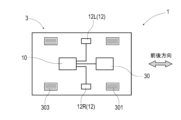
- FIG. 1 is an explanatory diagram showing the configuration of a vehicle in Example 1.
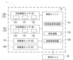
- FIG. 1 is a diagram showing a system configuration of a vehicle system in Example 1.
- FIG. 3 is a flowchart showing the flow of displacement measurement using a ground speed sensor in Example 1.
- FIG. 3 is an explanatory diagram showing how a previous image and a latest image are compared in Example 1.
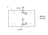
- FIG. 3 is an explanatory diagram of ground speed measured by a pair of left and right ground speed sensors in Example 1.
- FIG. FIG. 4 is an explanatory diagram of the sideslip angle ⁇ of the vehicle in Example 1.
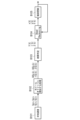
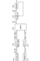
- FIG. FIG. 2 is a processing block diagram of autonomous navigation using a ground speed sensor in Embodiment 1.
- FIG. FIG. 2 is an explanatory diagram showing the configuration of a vehicle in Example 2.
- FIG. FIG. 3 is a diagram showing a system configuration of a vehicle system in Example 2.
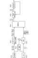
- FIG. FIG. 3 is a processing block diagram of autonomous navigation using a ground speed sensor and a wheel speed sensor in Embodiment 2.
- FIG. 7 is a diagram showing a system configuration of a vehicle system in Example 3.
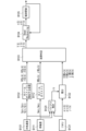
- FIG. 3 is a processing block diagram of autonomous navigation using a ground speed sensor and IMU in Embodiment 3.
- FIG. 7 is a diagram showing a system configuration of a vehicle system in Example 4.
- FIG. 4 is an explanatory diagram of autonomous navigation using a ground speed sensor, a wheel speed sensor, and an IMU in Example 4.
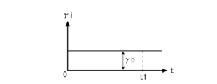
- 7 is a graph showing the yaw rate during straight running in Example 5.
- Example 1 This example is an example regarding a positioning system 1 for a vehicle. The contents will be explained using FIGS. 1 to 7.
- the positioning system 1 of this example is a system that measures the position of a vehicle by autonomous navigation, which is an example of a positioning method.
- the position of the vehicle is determined using a pair of left and right ground speed sensors 12L and 12R arranged on the left and right sides of the vehicle 3.
- the own vehicle position measured by the positioning system 1 is input to the vehicle ECU 30 in order to implement, for example, driving support control, automatic travel control, and the like.
- the vehicle ECU 30 uses the own vehicle position determined by the positioning system 1 to execute driving control of the vehicle 3.
- the vehicle ECU 30 controls an engine throttle actuator, a steering actuator, a brake actuator, etc. (not shown) so that the vehicle 3 travels along a preset route.
- the positioning system 1 includes a pair of left and right ground speed sensors 12L and 12R disposed on the left and right sides of the vehicle 3, and a control unit 10 that performs positioning calculations and the like.
- the control unit 10 has the functions of a physical quantity calculation circuit (an example of a first physical quantity calculation circuit) 101, a positioning circuit 103, and a failure diagnosis circuit 105.
- the physical quantity calculation circuit 101 is a circuit that calculates one or more physical quantities necessary for autonomous navigation based on the outputs of the pair of left and right ground speed sensors 12L and 12R.
- the positioning circuit 103 is a circuit that measures a position relative to a reference position.
- the failure diagnosis circuit 105 is a circuit that diagnoses the operating state of the ground speed sensors 12L and 12R.
- the ground speed sensors 12L and 12R are sensors that optically detect the speed relative to the road surface (ground speed).
- the ground speed sensors 12L and 12R include a light source element 121 for emitting blue laser light, an image sensor 123 that images the road surface, and a measurement circuit 120 that processes the captured image.
- the light source element 121 is an element that irradiates a certain amount of area on the road surface with blue laser light.
- the image sensor 123 is a camera that images the area illuminated by the light source element 121.
- the image sensor 123 is controlled to perform an imaging operation in synchronization with the light emission operation of the light source element 121.
- the measurement circuit 120 is a circuit that calculates ground speed.
- the measurement circuit 120 of this example calculates the ground speed using continuous images that are captured continuously over time.
- the measurement circuit 120 shifts the temporally preceding image and examines the degree of coincidence by superimposing it on the temporally subsequent image.
- the measurement circuit 120 then identifies the displacement between the images by identifying the shift amount by which the temporally preceding image most closely matches the subsequent image.
- the measurement circuit 120 determines the ground speed in the longitudinal direction and the ground speed in the lateral direction based on the displacement specified in this way, and outputs them as sensor signals of the ground speed sensors 12L and 12R.
- FIG. 3 is a flow diagram showing the flow of displacement measurement.
- FIG. 4 is an explanatory diagram of how the previous image and the latest image are compared. Note that the measurement circuit 120 executes the process shown in the flowchart of FIG. 3 for the pair of left and right ground speed sensors 12L and 12R, respectively.
- the measurement circuit 120 controls the light source element 121 and the image sensor 123 so that the light emitting operation and the imaging operation are executed in synchronization. Note that the imaging operation and the like are performed at a frequency of 3 kHz, for example.
- the image sensor 123 images the area illuminated by the light source element 121 on the road surface (S101).
- the measurement circuit 120 compares the previous image, which is the previous captured image, and the latest image, which is the latest captured image (S102).
- the previous image is an image acquired in the previous processing loop.
- the latest image is the image acquired in the immediately previous step S101.
- the measurement circuit 120 checks the correlation (degree of coincidence) with the latest image while shifting the previous image in the x and y directions.
- the measurement circuit 120 calculates the correlation coefficient with the latest image for each position where the previous image was shifted, and identifies the position where the correlation coefficient is the largest among the positions where the previous image was shifted. In this way, the measurement circuit 120 specifies the two-dimensional displacement amount on the imaging plane by specifying the position where the correlation coefficient is the largest (S103).
- the two-dimensional displacement amount is a combination of the displacement amount in the x direction, which corresponds to the front-back direction, and the displacement amount in the y direction, which corresponds to the lateral direction.
- the measurement circuit 120 After identifying the two-dimensional displacement amount in this way, the measurement circuit 120 stores and saves the latest image acquired in step S101 above as the previous image (S104). If the latest image is stored and saved in this way, it can be referenced as the previous image in the next processing loop.
- the measurement circuit 120 calculates the longitudinal speed (ground speed) and the lateral speed (ground speed) based on the two-dimensional displacement amount specified in step S103 (S105). Then, it is output as a sensor signal to the control unit 10 (S106).
- the longitudinal velocity by the left ground speed sensor 12L is Vglx and the lateral velocity is Vgly
- the longitudinal velocity by the right ground speed sensor 12R is Vgrx
- the lateral velocity is Vgry.
- the control unit 10 is a unit that calculates relative position from ground speed (Vglx, Vgly, Vgrx, Vgry).
- the control unit 10 controls the ground speed sensors 12L and 12R to detect the ground speed (Vglx, Vgly, Vgrx, Vgry).
- the control unit 10 includes an electronic board (not shown) on which a CPU (central processing unit) that executes various calculations and memory elements such as ROM (read only memory) and RAM (random access memory) are mounted. .
- the control unit 10 includes an input/output port with the outside. These are input ports for sensor signals of the ground speed sensors 12L and 12R, output ports for control signals for the ground speed sensors 12L and 12R, output ports for positioning information based on autonomous navigation, and the like.
- the control unit 10 realizes the following functions as each circuit when the CPU executes a software program read from the ROM.
- Physical quantity calculation circuit An example of a first physical quantity calculation circuit that calculates one or more physical quantities necessary for autonomous navigation from the ground speed detected by the pair of left and right ground speed sensors 12L and 12R.
- Positioning circuit A circuit that measures the relative position to the reference position and the relative direction to the reference direction.
- Failure diagnosis circuit A circuit that diagnoses failures of the ground speed sensors 12L and 12R.
- the control unit 10 calculates the longitudinal velocity VGSx and the lateral velocity VGSy of the vehicle 3 according to the following equation 1. , yaw rate ⁇ GS, sideslip angle ⁇ GS, and other physical quantities are calculated.
- TR in Equation 1 is the distance between the left and right pair of ground speed sensors 12L and 12R, and corresponds to the tread width of the vehicle 3.
- the sideslip angle ⁇ is the deviation angle of the vehicle 3 in the longitudinal direction with respect to the traveling direction of the vehicle 3.
- the control unit 10 calculates the above-mentioned physical quantity every time it acquires the sensor signals of the ground speed sensors 12L and 12R at the sampling period TS.
- (k) attached to each physical quantity, (k-1), etc. mentioned below mean the sampling period.
- (k) means a physical quantity calculated during the latest sampling cycle
- (k-1) means a physical quantity calculated during the previous sampling cycle. are doing.
- the processing procedure by the positioning system 1 of this example can be expressed as in the processing block diagram of FIG. Processing similar to wheel odometry is performed based on the ground speed (Vgrx, Vgry, Vglx, Vgly) detected by ground speed measurement (B101). Through this process, physical quantities such as the longitudinal speed VGSx(k), the lateral speed VGSy(k), the yaw rate ⁇ GS(k), and the sideslip angle ⁇ GS(k) are determined (B102).
- These physical quantities are diagnosed by the above-mentioned failure diagnosis circuit 105 to determine whether the values are within an appropriate range (B103). If the values of physical quantities such as longitudinal velocity VGSx(k), lateral velocity VGSy(k), yaw rate ⁇ GS(k), sideslip angle ⁇ GS(k), etc. are appropriate, the control unit 10 adjusts the longitudinal velocity based on these physical quantities. Directional velocity V(k), yaw rate ⁇ (k), and sideslip angle ⁇ (k) are generated. Then, positioning is performed by autonomous navigation based on the longitudinal velocity V(k), yaw rate ⁇ (k), and sideslip angle ⁇ (k) (B104, Dead Reckoning). In this autonomous navigation, the vehicle position (x, y) and vehicle direction ⁇ are determined.
- Positioning by autonomous navigation is performed every time the ground speed is acquired at the sampling period TS. For example, if the positioning result by autonomous navigation at the time of the previous sampling is the own vehicle position (x (k-1), y (k-1)) and vehicle direction ⁇ (k-1), then the latest sampling
- the vehicle position (x(k), y(k)) and vehicle orientation ⁇ (k) at the time can be estimated using the following equations.
- x(k-1), y(k-1), and ⁇ (k-1) on the right side of Equation 2 are the reference position or reference orientation.
- the terms added to x(k-1), y(k-1), and ⁇ (k-1) are relative positions or relative orientations.
- the vehicle position and the vehicle position are determined by positioning using a magnetic marker whose installation position is known, positioning by GNSS (Global Navigation Satellite System), or the like.
- GNSS Global Navigation Satellite System
- the latest vehicle position and vehicle position are updated based on the highly accurate vehicle position, etc.
- B105 Observation Update
- B104 Dead Reckoning
- positioning is performed using the vehicle position after observation update as a reference position, etc.
- the positioning system 1 of this example configured as described above is a system configured using a pair of left and right ground speed sensors 12L and 12R.
- the ground speed sensors 12L and 12R By using the ground speed sensors 12L and 12R, it is possible to obtain the lateral speed VGSy(k) of the vehicle in addition to the longitudinal speed VGSx(k).
- the longitudinal speeds Vglx and Vgrx obtained by the left and right ground speed sensors 12L and 12R it is possible to estimate the yaw rate ⁇ GS(k).
- the sideslip angle ⁇ GS(k) of the vehicle 3 can be estimated based on the combination of the longitudinal speed VGSx(k) and the lateral speed VGSy(k).
- the ground speed sensor 12L determines whether the physical quantities such as the longitudinal speed VGSx(k), the lateral speed VGSy(k), the yaw rate ⁇ GS(k), and the sideslip angle ⁇ GS(k) are within appropriate ranges. ⁇ Diagnosing the failure of R.
- Other methods for diagnosing the operating status of the ground speed sensors 12L and 12R include determining a failure when the difference between the left and right ground speeds is greater than a threshold, or determining the trend of the left and right ground speeds (for the most recent predetermined period) Possible methods include determining a failure when a sudden change occurs in the average value).
- Example 2 This example is an example in which wheel speed sensors 14L and 14R are provided on the left and right wheels based on the positioning system of Example 1.
- failure diagnosis can be performed using a combination of ground speed and wheel speed. The contents will be explained with reference to FIGS. 8 to 10.
- the wheel speed sensors 14L and 14R are sensors that detect the amount of rotation of the wheels 301, and are used to detect the wheel speed.
- the positioning system 1 of this example is a system configured based on the positioning system of the first embodiment by adding wheel speed sensors 14L and 14R for the left and right wheels 301.
- the distance per unit time that the corresponding wheel 301 rotates that is, the longitudinal speed can be obtained (second physical quantity calculation circuit).
- the vehicle Physical quantities such as the longitudinal velocity VWSx(k) and the yaw rate ⁇ WS(k) of No. 3 can be calculated. Note that it is difficult to estimate the lateral speed and sideslip angle by wheel odometry based on the longitudinal speeds Vwlx and Vwrx of the left and right wheels.
- physical quantities based on the outputs of the pair of left and right ground speed sensors 12L and R, and physical quantities based on the outputs of the left and right wheel speed sensors 14L and R are obtained as physical quantities for autonomous navigation.
- physical quantities such as longitudinal speed VGSx(k), lateral speed VGSy(k), sideslip angle ⁇ GS(k), and yaw rate ⁇ GS(k) can be calculated.
- physical quantities such as the longitudinal speed VWSx(k) and the yaw rate ⁇ WS(k) can be calculated.
- the processing procedure of the positioning system 1 of this example can be expressed as in the processing block diagram of FIG. 10.
- the difference from the processing procedure by the positioning system of Example 1 (see FIG. 7) is that wheel speed measurement (B111) and wheel odometry (B112) are added, and the processing content of failure determination (B103) is different. There are some things that have changed.
- the processing of vehicle speed wheel measurement (B111) and hole odometry (B112) is as described above.
- the processing results are compared between wheel speed measurement (B111) and wheel odometry (B112). Specifically, the results obtained by B102 (VGSx(k), ⁇ GS(k)) and the results obtained by B111 (VWSx(k), ⁇ WS(k)) are compared. If the deviation between VGSx(k) and VWSx(k) is less than a preset threshold, VWSx(k) is used as the longitudinal speed V for autonomous navigation.
- ⁇ GS(k) and ⁇ WS(k) are used as the yaw rate ⁇ for autonomous navigation (Dead Reckoning).
- ⁇ GS(k) from B102 is used as is as ⁇ (k) for autonomous navigation.
- VGSx(k) and VWSx(k) If the deviation between VGSx(k) and VWSx(k) is greater than or equal to a preset threshold, or if the deviation between ⁇ GS(k) and ⁇ WS(k) is greater than or equal to a preset threshold, It is determined that one of the wheel speed sensors 12L and 12L and R and the wheel speed sensor 14L and R is malfunctioning (B103). In the case of a failure determination, it may be possible to display a message to the effect of failure, and it is also good to cancel vehicle control such as automatic driving.
- a failure of the system can be determined by comparing the physical quantity based on the ground speed and the physical quantity based on the wheel speed.
- the positioning system 1 when a failure occurs in the ground speed sensors 12L/R or the wheel speed sensors 14L/R, or when a tendency toward failure appears, the failure or a sign of failure can be quickly detected, and the failure can be immediately notified. , it is now possible to immediately stop vehicle control that uses autonomous navigation.
- VWSx or ⁇ WS based on the wheel speed is used as the longitudinal speed V and yaw rate ⁇ . Instead, it is also good to selectively use VGSx ( ⁇ GS) based on ground speed and VWSx ( ⁇ WS) based on wheel speed, whichever can be expected to have higher accuracy.
- VGSx ( ⁇ GS) based on ground speed and VWSx ( ⁇ WS) based on wheel speed is more accurate, for example, focusing on the fact that the ground speed sensor is easily affected by ambient light. It is also good to adopt the judgment of whether the room is indoors or not. It is also good to define in advance which one of VGSx ( ⁇ GS) based on ground speed and VWSx ( ⁇ WS) based on wheel speed is to be adopted as map information for automatic driving.
- VGSx ( ⁇ GS) and VWSx ( ⁇ WS) it is preferable to link information indicating which of VGSx ( ⁇ GS) and VWSx ( ⁇ WS) can be expected to have higher accuracy to each position on the map data used for vehicle travel.
- VGSx ( ⁇ GS) and VWSx ( ⁇ WS) it is possible to easily understand which of VGSx ( ⁇ GS) and VWSx ( ⁇ WS) can be expected to have higher accuracy at the current vehicle position.
- Relative position is a positional change caused by movement after passing a reference position. A position shifted from the reference position by this relative position can be specified as the latest (current) vehicle position after movement.
- the question is whether to use the vehicle position based on the physical quantity VGSx ( ⁇ GS) or whether to use the vehicle position based on the physical quantity VWSx ( ⁇ WS).
- VGSx physical quantity
- VWSx physical quantity
- a physical quantity linked to the latest (current) vehicle position may be selectively used.
- the physical quantity linked to the reference position on the map data is selectively used. Just do it.
- Example 3 This example is an example in which an IMU 15 is added based on the positioning system of Example 1.
- failure diagnosis can be performed using a combination of the ground speed sensors 12L and 12R and the IMU 15. The contents will be explained with reference to FIGS. 11 and 12.
- the IMU 15 is an inertial navigation unit, and includes a two-axis acceleration sensor 152 that measures longitudinal acceleration ⁇ ix and lateral acceleration ⁇ iy, a gyro sensor (an example of a yaw rate sensor) 154 that measures yaw rate ⁇ i, etc. Figure 11). Note that the two-axis acceleration sensor 152 and the gyro sensor 154 are unavoidably biased to some extent due to changes in time measurement, temperature changes, and the like. Bias is the output when the change in acceleration or yaw is zero, that is, the zero point shift.
- the value obtained by subtracting the longitudinal acceleration bias ⁇ bx and the lateral acceleration bias ⁇ by from the longitudinal acceleration ⁇ ix or lateral acceleration ⁇ iy measured by the two-axis acceleration sensor 152 is the longitudinal acceleration and lateral acceleration. Treated as a valid measurement of acceleration. Furthermore, the value obtained by subtracting the yaw rate bias ⁇ b from the yaw rate ⁇ i measured by the gyro sensor 154 is treated as the correct measured value of the yaw rate.
- the processing procedure of the positioning system 1 of this example can be expressed as in the processing block diagram of FIG. 12.
- the difference from the processing procedure by the positioning system of Example 1 (see FIG. 7) is that bias estimation of yaw rate etc. (B120), measurement by IMU 15 (B121), and integral processing (B122) are added. and the processing contents of failure determination (B103) have been changed.
- a stop determination is executed when the ground speed is zero.
- whether or not the ground speed is zero may be determined based on sensor signals from the ground speed sensors 12L and 12R. There may also be a slight zero point shift in the sensor signals of the ground speed sensors 12L and 12R. Therefore, it is also good to perform threshold processing on the value represented by the sensor signal.
- the values represented by the sensor signals of the ground speed sensors 12L and 12R both belong to a predetermined range centered on zero, it can be determined that the ground speed is zero.
- the yaw rate (an example of a sensor output) output by the IMU 15 should originally be zero.
- zero point deviation (offset error) in the yaw rate and the like measured by the IMU 15 is unavoidable due to changes over time, temperature changes, and the like.
- the accelerations ⁇ ix, ⁇ iy, and yaw rate ⁇ i by the IMU 15 when the stop is determined are equal to the longitudinal acceleration bias ⁇ bx, the lateral acceleration bias ⁇ by, and the yaw rate bias ⁇ b due to the zero point shift.
- the yaw rate ⁇ i which is the sensor output of the gyro sensor 154 under a stop determination, is treated as the bias ⁇ b.
- Bias ⁇ b is the sensor output of gyro sensor 154 when the yaw rate is zero.
- longitudinal acceleration ⁇ ix, lateral acceleration ⁇ iy, and yaw rate ⁇ i are measured. Then, in the integration process of B122, the longitudinal speed VIMUx(k), the lateral speed VIMUy(k), the yaw rate ⁇ IMU(k), and the sideslip angle ⁇ IMU(k) are determined by integrating the measured values by the IMU 15. In this integration process, the integral calculation is executed with high precision by taking into account the longitudinal acceleration bias ⁇ bx, the lateral acceleration bias ⁇ by, and the yaw rate bias ⁇ b.
- the longitudinal speed VIMUx (k), the lateral speed VIMUy (k), the yaw rate ⁇ IMU (k), and the sideslip are determined by the following equation 4.
- the angle ⁇ IMU(k) can be obtained (third physical quantity calculation circuit). Note that integration is required when determining velocity from acceleration.
- the rate of change in the sampling period can be determined by integrating the acceleration measured in the latest sampling period by the sampling period TS.
- the latest speeds (VIMUx (k), VIMUy ( k)) can be obtained.
- the yaw rate ⁇ IMU(k) can be determined based on the yaw rate ⁇ i measured at the latest sampling period.
- the sideslip angle ⁇ IMU(k) can be determined using the longitudinal velocity VIMUx(k) and the lateral velocity VIMUy(k) determined at the latest sampling period.
- the speed of the previous sampling period is VIMUx (k-1)
- the latest speed is VIMUx (k), etc., by k, k-1, etc. in parentheses attached to variables, Represents the sampling period.
- the results of B102 (VGSx(k), ⁇ GS(k), ⁇ GS(k)) and the results of B122 (VIMUx(k), ⁇ IMU(k)) are used for longitudinal speed, yaw rate, and sideslip angle. , ⁇ IMU(k)) are compared. If the deviation between VGSx(k) and VIMUx(k) is less than a preset threshold, VIMUx(k) and VIMUy(k), which are physical quantities derived from the IMU 15, are used as physical quantities for autonomous navigation. Ru.
- ⁇ IMU(k) is used as the yaw rate ⁇ (k) for autonomous navigation. If the deviation between ⁇ GS(k) and ⁇ IMU(k) is less than a preset threshold, ⁇ IMU(k) is used as the sideslip angle ⁇ (k) for autonomous navigation.
- VGSx(k) VGSy(k)
- VIMUx(k) VIMUy(k)
- a failure is determined in B103. In the case of a failure determination, it may be possible to display a message to the effect of failure, and it is also good to cancel vehicle control such as automatic driving. Note that the other configurations and effects are the same as in Example 1.
- Example 4 This example is an example of a positioning system 1 that combines ground speed sensors 12L and R, wheel speed sensors 14L and R, and an IMU 15 based on the positioning systems of Examples 1 to 3. The contents will be explained with reference to FIGS. 13 and 14.
- the positioning system 1 of this example is a system that executes autonomous navigation by a combination of ground speed sensors 12L and R, wheel speed sensors 14L and R, and IMU 15 (FIG. 13).
- this positioning system 1 three types of sensors, ie, ground speed sensors 12L and R, wheel speed sensors 14L and R, and IMU 15, are made redundant and robustness is improved.
- the IMU 15 is employed as the main system. If B103 (FIG. 14) is determined to be normal as a result of failure determination, autonomous navigation (B104, Dead Reckoning) is executed.
- Example 5 This example is based on the configuration of the third embodiment and relates to another method for estimating the yaw rate bias. In this example, two types of bias estimation methods will be explained with reference to FIGS. 15 to 17.
- the bias estimation method of this example is a method that utilizes magnetic markers placed on the running track to enable observation of the vehicle's position.
- This bias estimation method uses the lateral deviation between the own vehicle position determined by autonomous navigation and the own vehicle position (observed position) specified using a magnetic marker, and uses the bias ⁇ b of the yaw rate output by the IMU 15 to is estimated.
- bias estimation methods an estimation method when the vehicle is traveling in a straight line and an estimation method when the vehicle is traveling on a curve will be described.
- This is a method for estimating yaw rate bias ⁇ b under the assumption that vehicle speed V is constant.
- the yaw rate bias ⁇ b is estimated as follows. can.
- Equation 5 The yaw angle error ⁇ 1 due to autonomous navigation is as shown in Equation 5.
- the bias ⁇ b can be calculated as shown in equation 6 using the yaw angle error ⁇ 1 determined by equation 5.
- the bias ⁇ b can be estimated using the two-dimensional coordinate position (x, y) of the vehicle's position determined using the magnetic marker.
- a lateral deviation ye occurs in the own vehicle position based on the autonomous navigation with respect to the own vehicle position (observed position) based on the magnetic marker.
- This lateral deviation ye can be expressed as in Equation 7 including vehicle speed V. Note that Equation 7 is an equation that includes engineering approximation based on the fact that ⁇ 1 is sufficiently small.
- bias ⁇ b can be expressed as shown in Equation 8.
- This estimation method is based on the assumption that the vehicle speed V is constant, that is, the vehicle is making a steady circular turn, and the yaw rate (true value) is constant at ⁇ t.
- the yaw angle displacement ⁇ 2 (turning angle) due to autonomous navigation can be expressed as in Equation 9.
- the displacement y2 in the Y direction due to autonomous navigation can be expressed as shown in Equation 10.
- the true displacement y1 in the Y direction is as shown in Equation 11 including the true yaw rate ⁇ t. Therefore, the lateral deviation ye of the own vehicle position based on the autonomous navigation with respect to the own vehicle position (observation position) based on the magnetic marker can be expressed as shown in Equation 12.
- bias ⁇ b can be estimated as shown in Equation 13 below.
- Positioning System 10 Control Unit 101 Physical Quantity Calculation Circuit 103 Positioning Circuit 105 Failure Diagnosis Circuit 12 Ground Speed Sensor 14 Wheel Speed Sensor 15 IMU 3 Vehicle 30 Vehicle ECU 301 Wheel
Landscapes
- Engineering & Computer Science (AREA)
- Radar, Positioning & Navigation (AREA)
- Remote Sensing (AREA)
- Automation & Control Theory (AREA)
- Physics & Mathematics (AREA)
- General Physics & Mathematics (AREA)
- Navigation (AREA)
Abstract
車両用の測位システム(1)は、路面に相対する速度である対地速度を光学的に検出する左右一対の対地速度センサ(12)と、左右一対の対地速度センサ(12)が検出した対地速度から自律航法に必要な物理量を求める物理量演算回路(101)と、車両が基準位置を通過して移動したときに基準位置に対する相対位置を測位する測位回路(103)と、を含み、測位回路(103)は、物理量演算回路(101)が求めた物理量を利用して相対位置を測位する。
Description
本発明は、車両の位置を測位するための測位方法及び測位システムに関する。
従来より、衛星電波を利用するGNSS(Global Navigation Satellite System)を利用する車両用のナビゲーション装置や運転支援装置や自動運転装置などが実現されている(例えば下記の特許文献1参照。)。GNSSは、複数の人工衛星から送信されて来る衛星電波を受信できる環境下で有効に動作する。一方、トンネル内やビルの谷間など、電波の受信状態が良好でない環境では、GNSSによる測位が困難となったり、測位精度を確保できなくなることがある。
そこで、車両用のナビゲーション装置や運転支援装置や自動運転装置などでは、GNSSによる測位に対して、自律航法(推測航法、慣性航法、Dead Reckoning)による測位が組み合わせられる。このような組み合わせによれば、衛星電波を受信できない環境下での自車位置の測位が可能になる。車両用の各装置に適用する自律航法としては、車輪速センサ、ヨーレートセンサ、加速度センサ、電子コンパス、ジャイロセンサ等を利用する各種の自律航法が知られている。
自律航法などの測位方法の信頼性を向上すれば自車位置の測位精度を向上でき、車両用の各装置の動作信頼性を向上できることから、信頼性の高い車両用の測位方法あるいは測位システムが求められている。
本発明は、信頼性の高い車両用の測位方法及び測位システムを提供しようとするものである。
本発明の一態様は、車両用の測位システムであって、
路面に相対する速度である対地速度を光学的に検出する左右一対の対地速度センサと、
該左右一対の対地速度センサが検出した対地速度から自律航法に必要な1又は2以上の複数の物理量を求める第1の物理量演算回路と、
車両が基準位置を通過して移動したときに当該基準位置に対する相対位置を測位する測位回路と、を含み、
前記測位回路は、前記第1の物理量演算回路が求めた複数の物理量を利用して前記相対位置を測位できるように構成されている車両用の測位システムにある。
路面に相対する速度である対地速度を光学的に検出する左右一対の対地速度センサと、
該左右一対の対地速度センサが検出した対地速度から自律航法に必要な1又は2以上の複数の物理量を求める第1の物理量演算回路と、
車両が基準位置を通過して移動したときに当該基準位置に対する相対位置を測位する測位回路と、を含み、
前記測位回路は、前記第1の物理量演算回路が求めた複数の物理量を利用して前記相対位置を測位できるように構成されている車両用の測位システムにある。
本発明の一態様は、車両用の測位方法であって、
車両は、路面に沿う2次元方向の速度である対地速度を光学的に検出する左右一対の対地速度センサを有し、
該左右一対の対地速度センサが検出した対地速度から自律航法に必要な1又は2以上の複数の物理量を求め、
車両が基準位置を通過して移動したときに当該基準位置に対する相対位置を、前記対地速度に基づく複数の物理量を利用して測位可能な車両用の測位方法にある。
車両は、路面に沿う2次元方向の速度である対地速度を光学的に検出する左右一対の対地速度センサを有し、
該左右一対の対地速度センサが検出した対地速度から自律航法に必要な1又は2以上の複数の物理量を求め、
車両が基準位置を通過して移動したときに当該基準位置に対する相対位置を、前記対地速度に基づく複数の物理量を利用して測位可能な車両用の測位方法にある。
本発明は、左右一対の対地速度センサを利用する測位方法あるいは測位システムである。対地速度センサは、対地速度を光学的に計測するセンサである。この対地速度センサは、経時変化や温度変化等の影響により計測結果が変動するおそれが少ない。よって、対地速度センサを利用すれば、信頼性の高い測位方法あるいは測位システムを実現できる可能性がある。
本発明の実施の形態につき、以下の実施例を用いて具体的に説明する。
(実施例1)
本例は、車両用の測位システム1に関する例である。この内容について、図1~図7を用いて説明する。
本例の測位システム1は、測位方法の一例をなす自律航法により自車位置を測位するシステムである。測位システム1の自律航法では、車両3の左右両側に配置された左右一対の対地速度センサ12L・Rを利用して自車位置が測位される。測位システム1が測位する自車位置は、例えば運転支援制御や自動走行制御等を実現するために車両ECU30に入力される。
(実施例1)
本例は、車両用の測位システム1に関する例である。この内容について、図1~図7を用いて説明する。
本例の測位システム1は、測位方法の一例をなす自律航法により自車位置を測位するシステムである。測位システム1の自律航法では、車両3の左右両側に配置された左右一対の対地速度センサ12L・Rを利用して自車位置が測位される。測位システム1が測位する自車位置は、例えば運転支援制御や自動走行制御等を実現するために車両ECU30に入力される。
車両ECU30は、測位システム1が測位した自車位置を利用し、車両3の走行制御を実行する。車両ECU30は、予め設定された経路に沿って車両3を走行させるよう、図示しないエンジンスロットルアクチュエータやステアリングアクチュエータやブレーキアクチュエータ等を制御する。
以下、本例の測位システム1の構成及び動作について説明する。
測位システム1は、図1及び図2のごとく、車両3の左右両側に配置された左右一対の対地速度センサ12L・Rと、測位演算等を実行する制御ユニット10と、を含めて構成されている。制御ユニット10は、物理量演算回路(第1の物理量演算回路の一例)101の機能と、測位回路103の機能と、故障診断回路105の機能と、を有している。物理量演算回路101は、左右一対の対地速度センサ12L・Rの出力を元にして自律航法に必要な1又は2以上の複数の物理量を求める回路である。測位回路103は、基準位置に対する相対位置を測位する回路である。故障診断回路105は、対地速度センサ12L・Rの動作状態を診断する回路である。
測位システム1は、図1及び図2のごとく、車両3の左右両側に配置された左右一対の対地速度センサ12L・Rと、測位演算等を実行する制御ユニット10と、を含めて構成されている。制御ユニット10は、物理量演算回路(第1の物理量演算回路の一例)101の機能と、測位回路103の機能と、故障診断回路105の機能と、を有している。物理量演算回路101は、左右一対の対地速度センサ12L・Rの出力を元にして自律航法に必要な1又は2以上の複数の物理量を求める回路である。測位回路103は、基準位置に対する相対位置を測位する回路である。故障診断回路105は、対地速度センサ12L・Rの動作状態を診断する回路である。
対地速度センサ12L・Rは、路面に相対する速度(対地速度)を光学的に検出するセンサである。対地速度センサ12L・Rは、青色レーザ光の光源素子121と、路面を撮像する撮像素子123と、撮像画像を処理する計測回路120と、を備えている。光源素子121は、路面上のある程度の広さの領域に青色レーザ光を照射する素子である。撮像素子123は、光源素子121による照射領域を撮像するカメラである。撮像素子123は、光源素子121の発光動作に同期して撮像動作を実行するように制御される。
計測回路120は、対地速度を求める回路である。本例の計測回路120は、時間的に連続して撮像された連続画像を利用して対地速度を求める。計測回路120は、時間的に先行する画像をずらしながら、時間的に後の画像に重ね合わせ一致度合いを調べる。そして、計測回路120は、時間的に先行する画像が後の画像に最も一致するずらし量を特定することで、画像間の変位を特定する。計測回路120は、このように特定された変位に基づいて前後方向の対地速度及び横方向の対地速度を求め、対地速度センサ12L・Rのセンサ信号として出力する。
対地速度センサ12による変位計測の内容について、計測回路120の動作を主体として図3及び図4を参照しながら説明する。図3は、変位計測の流れを示すフロー図である。図4は、前回画像と最新画像とを比較する様子の説明図である。なお、計測回路120は、左右一対の対地速度センサ12L・Rについて、図3のフロー図の処理をそれぞれ実行する。
計測回路120は、発光動作と撮像動作とが同期して実行されるよう、光源素子121と撮像素子123とを制御する。なお、撮像動作等は、例えば3kHzの周波数で実行される。撮像素子123は、光源素子121による路面上の照射領域を撮像する(S101)。
計測回路120は、前回の撮像画像である前回画像と、最新の撮像画像である最新画像と、の比較を実行する(S102)。前回画像は、前回の処理ループで取得された画像である。最新画像は、直前のステップS101で取得された画像である。具体的には、計測回路120は、図4のように、前回画像をx方向、y方向にずらしながら最新画像との相関(一致度合い)を調べる。
計測回路120は、前回画像をずらした位置毎に、最新画像との相関係数を求め、前回画像をずらした位置のうち、相関係数が最も大きくなる位置を特定する。計測回路120は、このように、相関係数が最も大きくなる位置を特定することにより、撮像面における2次元的な変位量を特定する(S103)。ここで、2次元的な変位量は、前後方向に当たるx方向の変位量と、横方向に当たるy方向の変位量と、の組合せである。
計測回路120は、このように2次元的な変位量を特定すると、上記のステップS101で取得された最新画像を前回画像として記憶し保存する(S104)。このように最新画像を記憶し保存すれば、次回の処理ループにて、前回画像として参照できるようになる。計測回路120は、上記のステップS103で特定された2次元的な変位量に基づいて、前後方向速度(対地速度)及び横方向速度(対地速度)を演算により求める(S105)。そして、制御ユニット10に向けてセンサ信号として出力する(S106)。
なお、以下の説明では、図5の通り、左の対地速度センサ12Lによる前後方向速度をVglx、横方向速度をVglyとし、右の対地速度センサ12Rによる前後方向速度をVgrx、横方向速度をVgryとする。計測回路120は、上記のステップS106において、前後方向速度Vglx・Vgrx、横方向速度Vgly・Vgryを表すセンサ信号を出力する。
次に、制御ユニット10(図2)について説明する。制御ユニット10は、対地速度(Vglx、Vgly、Vgrx、Vgry)から相対位置を演算するユニットである。制御ユニット10は、対地速度(Vglx、Vgly、Vgrx、Vgry)を検出するよう、対地速度センサ12L・Rを制御する。
制御ユニット10は、各種の演算を実行するCPU(central processing unit)やROM(read only memory)やRAM(random access memory)などのメモリ素子などが実装された電子基板(図示略)を備えている。制御ユニット10は、外部との入出力ポートを備えている。対地速度センサ12L・Rのセンサ信号の入力ポート、対地速度センサ12L・Rに対する制御信号の出力ポート、自律航法による測位情報の出力ポート、等である。
制御ユニット10は、ROMから読み出したソフトウェアプログラムをCPUが実行することにより、以下の各回路としての機能を実現する。
(1)物理量演算回路:左右一対の対地速度センサ12L・Rが検出した対地速度から自律航法に必要な1又は2以上の複数の物理量を求める第1の物理量演算回路の一例。
(2)測位回路:基準位置に対する相対位置、及び基準方位に対する相対方位を測位する回路。
(3)故障診断回路:対地速度センサ12L・Rの故障を診断する回路。
(1)物理量演算回路:左右一対の対地速度センサ12L・Rが検出した対地速度から自律航法に必要な1又は2以上の複数の物理量を求める第1の物理量演算回路の一例。
(2)測位回路:基準位置に対する相対位置、及び基準方位に対する相対方位を測位する回路。
(3)故障診断回路:対地速度センサ12L・Rの故障を診断する回路。
制御ユニット10は、左右一対の対地速度センサ12L・Rから前後方向速度Vglx・Vgrx、横方向速度Vgly・Vgryを取得すると、次式1の通り、車両3の前後方向速度VGSx、横方向速度VGSy、ヨーレートγGS、横滑り角βGS等の物理量を算出する。なお、式1中のTRは、左右一対の対地速度センサ12L・Rが離間する距離であり、車両3のトレッド幅に相当する。横滑り角βは、図6の通り、車両3の進行方向に対する車両3の前後方向の偏差角である。

制御ユニット10は、サンプリング周期TSにより対地速度センサ12L・Rのセンサ信号を取得する毎に、上記の物理量を算出する。上記の式1において各物理量に付された(k)や後出の(k-1)等は、サンプリングされた周期を意味している。例えば(k)は、最新のサンプリング周期の際に算出された物理量であることを意味し、例えば(k-1)は、1回前のサンプリング周期の際に算出された物理量であることを意味している。
本例の測位システム1では、車輪速による周知のホイールオドメトリに類似する手法により自律航法が実現される。本例の測位システム1による処理手順は、図7の処理ブロック図のように表すことができる。対地速度計測(B101)によって検出された対地速度(Vgrx、Vgry、Vglx、Vgly)に基づき、ホイールオドメトリに類似する処理が実行される。そして、この処理により、前後方向速度VGSx(k)、横方向速度VGSy(k)、ヨーレートγGS(k)、横滑り角βGS(k)等の物理量が求められる(B102)。
これらの物理量については、上記の故障診断回路105により適正な範囲の値であるかどうかの診断がなされる(B103)。前後方向速度VGSx(k)、横方向速度VGSy(k)、ヨーレートγGS(k)、横滑り角βGS(k)等の物理量の値が適正であれば、制御ユニット10がこれらの物理量に基づき、前後方向速度V(k)、ヨーレートγ(k)、横滑り角β(k)を生成する。そして、前後方向速度V(k)、ヨーレートγ(k)、横滑り角β(k)に基づいて自律航法による測位が行われる(B104、Dead Reckoning)。この自律航法では、自車位置(x、y)及び車両方位θが測位される。
自律航法(B104、Dead Reckoning)による測位は、サンプリング周期TSで対地速度が取得される毎に実行される。例えば、1回前のサンプリング時の自律航法による測位結果が自車位置(x(k-1)、y(k-1))、車両方位θ(k-1)であったとき、最新のサンプリング時の自車位置(x(k)、y(k))、車両方位θ(k)は、次式により推定できる。式2の右辺におけるx(k-1)、y(k-1)、θ(k-1)が基準位置あるいは基準方位である。x(k-1)、y(k-1)、θ(k-1)に加算される項が、相対位置あるいは相対方位である。

本例の構成では、敷設位置が既知の磁気マーカを利用する測位や、GNSS(Global Navigation Satellite System)による測位、等により自車位置および車両方位が測位される。これらの測位により、高精度の自車位置、車両方位を測位(観測)できたとき、その高精度の自車位置等により最新の自車位置および車両方位が更新される(B105、観測更新)。次回の自律航法(B104、Dead Reckoning)では、観測更新後の車両位置を基準位置等とする測位が実行される。
以上のように構成された本例の測位システム1は、左右一対の対地速度センサ12L・Rを利用して構成されたシステムである。対地速度センサ12L・Rを利用すれば、車両の前後方向速度VGSx(k)に加えて横方向速度VGSy(k)を取得できる。左右の対地速度センサ12L・Rによる前後方向速度Vglx、Vgrxによれば、ヨーレートγGS(k)の推定が可能である。さらに、前後方向速度VGSx(k)と横方向速度VGSy(k)との組合せによれば、車両3の横滑り角βGS(k)の推定が可能である。
本例では、前後方向速度VGSx(k)、横方向速度VGSy(k)、ヨーレートγGS(k)、横滑り角βGS(k)等の物理量が適正な範囲であるか否かにより、対地速度センサ12L・Rの故障を診断している。対地速度センサ12L・Rの動作状態を診断する方法としては、他に、左右の対地速度の差が閾値以上であるときに故障と判定したり、左右の対地速度のトレンド(直近の所定期間の平均値)に急激な変動が発生したときに故障と判定する、等の方法が考えられる。
(実施例2)
本例は、実施例1の測位システムに基づき、左右の車輪に車輪速センサ14L・Rを設けた例である。本例の測位システム1では、対地速度と車輪速との組合せによる故障診断が可能となっている。この内容について、図8~図10を参照して説明する。
本例は、実施例1の測位システムに基づき、左右の車輪に車輪速センサ14L・Rを設けた例である。本例の測位システム1では、対地速度と車輪速との組合せによる故障診断が可能となっている。この内容について、図8~図10を参照して説明する。
車輪速センサ14L・R(図8及び図9)は、車輪301の回転量を検出するセンサであり、車輪速を検出するために利用される。本例の測位システム1は、図9のごとく、実施例1の測位システムに基づき、左右の車輪301の車輪速センサ14L・Rを追加して構成されたシステムである。
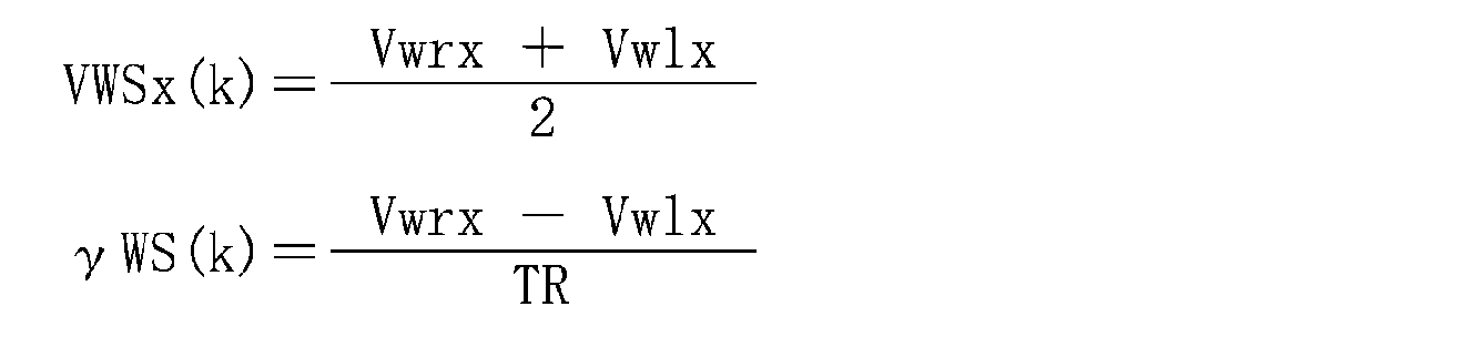
車輪速センサ14L・Rが出力するセンサ信号に基づけば、対応する車輪301が回転した単位時間当たりの距離、すなわち前後方向速度を取得できる(第2の物理量演算回路)。左の車輪301で検出された前後方向速度をVwlx、右の車輪301で検出された前後方向速度をVwrxとしたとき(図8参照。)、周知のホイールオドメトリに基づく次式3の通り、車両3の前後方向速度VWSx(k)、ヨーレートγWS(k)等の物理量を算出できる。なお、横方向速度及び横滑り角については、左右の車輪の前後方向速度Vwlx、Vwrxによるホイールオドメトリによって推定することは困難である。
本例の測位システム1では、左右一対の対地速度センサ12L・Rの出力に基づく物理量、及び左右輪の車輪速センサ14L・Rの出力に基づく物理量、を自律航法のための物理量として求めている。左右一対の対地速度センサ12L・Rによる対地速度に基づけば、前後方向速度VGSx(k)、横方向速度VGSy(k)、横滑り角γGS(k)、ヨーレートβGS(k)等の物理量を算出できる。左右の車輪速センサ14L・Rによる車輪速に基づけば、前後方向速度VWSx(k)、ヨーレートγWS(k)等の物理量を算出できる。
本例の測位システム1の処理手順は、図10の処理ブロック図のように表すことができる。実施例1の測位システムによる処理手順(図7参照。)との相違点は、車輪速計測(B111)およびホイールオドメトリ(B112)が追加されている点、及び故障判定(B103)の処理内容が変更されている点にある。車速輪計測(B111)及びホールオドメトリ(B112)の処理については、上記の通りである。
B103の故障判定では、車輪速計測(B111)とホイールオドメトリ(B112)との間で処理結果(前後方向速度及びヨーレート)が比較される。具体的には、B102による結果(VGSx(k)、γGS(k))と、B111による結果(VWSx(k)、γWS(k))と、が比較される。VGSx(k)とVWSx(k)との偏差が予め設定された閾値未満であれば、自律航法のための前後方向速度VとしてVWSx(k)が利用される。また、γGS(k)とγWS(k)との偏差が予め設定された閾値未満であれば、自律航法(Dead Reckoning)のためのヨーレートγとしてγWS(k)が利用される。なお、横滑り角β(k)については、B112のホイールオドメトリによっては取得できないので、B102によるβGS(k)がそのまま、自律航法のためのβ(k)として利用される。
なお、自律航法のための車速V(k)、ヨーレートγ(k)、横滑り角β(k)が定まった後の自律航法(B104、Dead Reckoning)による測位、及び観測更新(B105)については、実施例1と同様である。
VGSx(k)とVWSx(k)との偏差が予め設定された閾値以上であったり、γGS(k)とγWS(k)との偏差が予め設定された閾値以上であった場合、対地速度センサ12L・Rおよび車輪速センサ14L・Rのいずれかに故障が生じていると判定される(B103)。故障判定の場合、故障の旨を表示することも良く、自動運転等の車両制御を中止することも良い。
本例の測位システム1によれば、対地速度に基づく物理量と、車輪速に基づく物理量と、を比較することで、システムの故障を判定できる。測位システム1では、対地速度センサ12L・Rあるいは車輪速センサ14L・Rに故障が生じたときや、故障の傾向が現れたとき、故障や故障の前兆をいち早く検出でき、直ちに故障を報知したり、自律航法を利用する車両制御を直ちに停止させることが可能となっている。
本例では、故障と判定しない場合、前後方向速度V及びヨーレートγとして、車輪速に基づくVWSxあるいはγWSを利用している。これに代えて、対地速度に基づくVGSx(γGS)および車輪速に基づくVWSx(γWS)のうち、高精度を期待できる方を選択的に利用することも良い。
対地速度によるVGSx(γGS)と車輪速に基づくVWSx(γWS)のうちのどちらが高精度であるかの判断として、例えば、対地速度センサが外乱光の影響を受け易いことに着目して、屋外であるか屋内であるかの判断を採用することも良い。また、自動運転の地図情報として、対地速度によるVGSx(γGS)と車輪速に基づくVWSx(γWS)のうちのいずれを採用するか事前に定義しておくことも良い。
例えば、VGSx(γGS)及びVWSx(γWS)のうちのいずれが、より高精度を期待できるかを示す情報を、車両の走行に用いられる地図データ上の各位置にひも付けておくと良い。この場合には、車両の走行中に地図データを参照することで、現在の車両位置において、VGSx(γGS)及びVWSx(γWS)のうちのいずれが高精度を期待できるかを容易に把握できる。VGSx(γGS)及びVWSx(γWS)のうち、高精度が期待できる方の物理量を利用し相対位置を測位することも良い。相対位置は、基準位置を通過した後の移動により生じた位置的な変化である。この相対位置の分だけ、基準位置から位置的にずらした位置を、移動後の最新(現在)の車両位置として特定できる。
なお、地図データを参照する際、物理量VGSx(γGS)に基づく車両位置を利用するか、及び物理量VWSx(γWS)に基づく車両位置を利用するか、が問題となる。例えば、地図データ上における基準位置に、高精度を期待できるものとしてひも付けられた物理量を利用することができる。これに代えて、最新(現在)の車両位置にひも付けられた物理量を選択的に利用することも良い。例えば、地図データ上における前者の車両位置に、高精度を期待できるものとしてひも付けられた物理量と、後者の車両位置に、同様にひも付けられた物理量と、が一致する場合には、その物理量を選択的に利用すると良い。一方、前者の車両位置にひも付けられた物理量と、後者の車両位置にひも付けられた物理量と、が不一致の場合には、地図データ上における基準位置にひも付けられた物理量を選択的に利用すれば良い。
また例えば、対地速度、車輪速のいずれも異常がない場合で、車輪速に対して対地速度が小さくなっている場合には、車輪の空転の疑いがあることから、このような場合に、対地速度を採用することも良い。操舵角が閾値以上で横速度が発生している場合、横速度が現れない車輪速ではなく、対地速度を優先的に採用することも良い。
なお、その他の構成及び作用効果については、実施例1と同様である。
なお、その他の構成及び作用効果については、実施例1と同様である。
(実施例3)
本例は、実施例1の測位システムに基づき、IMU15を追加した例である。本例の測位システム1では、対地速度センサ12L・RとIMU15との組合せによる故障診断が可能となっている。この内容について、図11、図12を参照して説明する。
本例は、実施例1の測位システムに基づき、IMU15を追加した例である。本例の測位システム1では、対地速度センサ12L・RとIMU15との組合せによる故障診断が可能となっている。この内容について、図11、図12を参照して説明する。
IMU15は、慣性航法ユニットであり、前後方向加速度αix及び横方向加速度αiyを計測する2軸加速度センサ152や、ヨーレートγiを計測するジャイロセンサ(ヨーレートセンサの一例。)154、等を備えている(図11)。なお、2軸加速度センサ152及びジャイロセンサ154は、計時変化や温度変化等に起因するバイアスの発生がある程度、不可避である。バイアスとは、加速度あるいはヨーの変化がゼロであるときの出力、すなわちゼロ点ずれである。
本例の構成では、2軸加速度センサ152が計測する前後方向加速度αixあるいは横方向加速度αiyから、前後方向加速度のバイアスαbx、横方向加速度のバイアスαbyを差し引いた値が、前後方向加速度及び横方向加速度の正しい計測値として取り扱いされる。また、ジャイロセンサ154が計測するヨーレートγiから、ヨーレートのバイアスγbを差し引いた値が、ヨーレートの正しい計測値として取り扱いされる。
本例の測位システム1の処理手順は、図12の処理ブロック図のように表すことができる。実施例1の測位システムによる処理手順(図7参照。)との相違点は、ヨーレート等のバイアス推定(B120)、IMU15による計測(B121)、および積分処理(B122)が追加されている点、及び故障判定(B103)の処理内容が変更されている点にある。
B120のバイアス推定では、対地速度ゼロのときに停止判定を実行する。ここで、対地速度がゼロであるか否かは、対地速度センサ12L・Rのセンサ信号に基づいて判断すると良い。対地速度センサ12L・Rのセンサ信号についても、微小なゼロ点ずれが生じる場合がある。そこで、センサ信号が表す値について閾値処理を実行することも良い。対地速度センサ12L・Rのセンサ信号が表す値がいずれもゼロを中心とする所定範囲に属しているとき、対地速度がゼロであると判断できる。
車両が停止と判定された状態であれば、本来、IMU15が出力するヨーレート(センサ出力の一例)はゼロのはずである。しかしながら、現実的には、経時変化や温度変化等に起因し、IMU15が計測するヨーレート等のゼロ点ずれ(オフセット誤差)は不可避である。バイアス推定では、停止判定されたときのIMU15による加速度αix、αiy、ヨーレートγiが、ゼロ点ずれによる前後方向加速度のバイアスαbx、横方向加速度のバイアスαby、ヨーレートのバイアスγbに等しいと推定する。このようなバイアス推定が行われた後の処理では、停止判定下のジャイロセンサ154のセンサ出力であるヨーレートγiがバイアスγbとして取り扱いされる。バイアスγbは、ヨーレートがゼロのときのジャイロセンサ154のセンサ出力である。
B121のIMU15による計測では、前後方向加速度αix、横方向加速度αiy、ヨーレートγiが計測される。そしてB122の積分処理では、IMU15による計測値を積分することで、前後方向速度VIMUx(k)、横方向速度VIMUy(k)、ヨーレートγIMU(k)、横滑り角βIMU(k)が求められる。この積分処理では、前後方向加速度のバイアスαbx、横方向加速度のバイアスαby、ヨーレートのバイアスγbを考慮することで、精度高く積分演算が実行される。
IMU15による計測値αix、αiy及びγiと、バイアスαbx、αby及びγbと、に基づけば、次式4により前後方向速度VIMUx(k)、横方向速度VIMUy(k)、ヨーレートγIMU(k)、横滑り角βIMU(k)を求めることができる(第3の物理量演算回路)。なお、加速度から速度を求める際には積分が必要である。最新のサンプリング周期で計測された加速度にサンプリング周期TSを乗じる積分により、サンプリング周期における変化速度を求めることができる。1回前のサンプリング周期の際に求めた速度(VIMUx(k-1)、VIMUy(k-1))に対し、この変化速度を加算するれば、最新の速度(VIMUx(k)、VIMUy(k))を求めることができる。一方、ヨーレートγIMU(k)は、最新のサンプリング周期で計測されたヨーレートγiに基づいて求めることができる。横滑り角βIMU(k)については、最新のサンプリング周期で求められた前後方向速度VIMUx(k)及び横方向速度VIMUy(k)を利用して求めることができる。式4では、例えば、1回前のサンプリング周期の速度をVIMUx(k-1)、最新の速度をVIMUx(k)というように、変数に付されたかっこ内のkやk-1等により、サンプリング周期を表している。

B103の故障判定では、前後方向速度、ヨーレート及び横滑り角について、B102による結果(VGSx(k)、γGS(k)、βGS(k))と、B122による結果(VIMUx(k)、γIMU(k)、βIMU(k))と、が比較される。VGSx(k)とVIMUx(k)との偏差が予め設定された閾値未満であれば、自律航法のための物理量として、IMU15に由来する物理量であるVIMUx(k)、VIMUy(k)が利用される。また、γGS(k)とγIMU(k)との偏差が予め設定された閾値未満であれば、自律航法のためのヨーレートγ(k)としてγIMU(k)が利用される。βGS(k)とβIMU(k)との偏差が予め設定された閾値未満であれば、自律航法のための横滑り角β(k)としてβIMU(k)が利用される。
自律航法のための車速V(k)、ヨーレートγ(k)、横滑り角β(k)が定まった後の自律航法(B104、Dead Reckoning)による測位、及び観測更新(B105)については、実施例1と同様である。
なお、VGSx(k)(VGSy(k))とVIMUx(k)(VIMUy(k))との偏差が予め設定された閾値以上であったり、γGS(k)とγIMU(k)との偏差が予め設定された閾値以上であったり、βGS(k)とβIMU(k)との偏差が予め設定された閾値以上であったりした場合、B103において故障と判定される。故障判定の場合、故障の旨を表示することも良く、自動運転等の車両制御を中止することも良い。
なお、その他の構成及び作用効果については実施例1と同様である。
なお、その他の構成及び作用効果については実施例1と同様である。
(実施例4)
本例は、実施例1~実施例3の測位システムに基づき、対地速センサ12L・R、車輪速センサ14L・R、IMU15を組み合わせた測位システム1の例である。この内容について、図13及び図14を参照して説明する。
本例は、実施例1~実施例3の測位システムに基づき、対地速センサ12L・R、車輪速センサ14L・R、IMU15を組み合わせた測位システム1の例である。この内容について、図13及び図14を参照して説明する。
本例の測位システム1は、対地速度センサ12L・R、車輪速センサ14L・R、IMU15の組合せによって自律航法を実行するシステムである(図13)。この測位システム1では、対地速度センサ12L・R、車輪速センサ14L・R、IMU15という3種類のセンサによって冗長化され、ロバストネスが向上されている。
本例の測位システム1では、主系としてIMU15が採用されている。B103(図14)の故障判定の結果、正常と判定された場合、IMU15の計測値に由来する車速V(k)、ヨーレートγ(k)、横ずれ角β(k)に基づく自律航法(B104、Dead Reckoning)が実行される。
なお、その他の構成及び作用効果については、実施例1~実施例3のいずれかと同様である。
(実施例5)
本例は、実施例3の構成に基づき、ヨーレートのバイアスの他の推定方法に関する例である。本例では、2種類のバイアス推定方法を、図15~図17を参照して説明する。
本例は、実施例3の構成に基づき、ヨーレートのバイアスの他の推定方法に関する例である。本例では、2種類のバイアス推定方法を、図15~図17を参照して説明する。
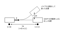
本例のバイアス推定方法は、自車位置の観測を可能とするために走路に敷設された磁気マーカを利用する方法である。このバイアス推定方法では、自律航法により測位された自車位置と、磁気マーカを利用して特定された自車位置(観測位置)と、の横偏差を利用し、IMU15が出力するヨーレートのバイアスγbが推定される。以下、バイアス推定方法として、直線走行時の推定方法および曲線走行時の推定手法を説明する。
(直線走行時のバイアス推定方法)
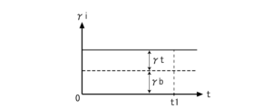
このバイアス推定方法は、いずれかの磁気マーカが検出された時刻t=0から、次の磁気マーカが検出される時刻t=t1までの間、ヨーレートγiがγbで一定(図15参照。)、車速Vが一定という仮定の下でのヨーレートバイアスγbの推定方法である。図16の通り、直進走行時につき真のヨーレートは0であるにも関わらずバイアスγbに起因し、自車位置の測位結果に横偏差yeが発生した場合、以下のようにヨーレートバイアスγbを推定できる。
このバイアス推定方法は、いずれかの磁気マーカが検出された時刻t=0から、次の磁気マーカが検出される時刻t=t1までの間、ヨーレートγiがγbで一定(図15参照。)、車速Vが一定という仮定の下でのヨーレートバイアスγbの推定方法である。図16の通り、直進走行時につき真のヨーレートは0であるにも関わらずバイアスγbに起因し、自車位置の測位結果に横偏差yeが発生した場合、以下のようにヨーレートバイアスγbを推定できる。
自律航法によるヨー角の誤差θ1は、式5の通りである。

よって、磁気マーカを利用してヨー角を特定できる場合であれば、式5で求められるヨー角の誤差θ1を利用し、式6の通りバイアスγbを算出できる。

一方、磁気マーカを利用してヨー角を特定できない場合には、磁気マーカを利用して特定された自車位置の2次元的な座標位置(x、y)を利用してバイアスγbを推定できる。図16のごとく、ヨーレートバイアスγbが存在する場合、磁気マーカに基づく自車位置(観測位置)に対し、自律航法による自車位置に横偏差yeが発生する。この横偏差yeは、車速Vを含む式7のように表すことができる。なお、式7は、θ1が十分に小さいことに基づく工学的な近似を含む式である。

式7の変形により、バイアスγbは、式8のように表すことができる。

lmは、時刻t=0から時刻t1までの期間における車両の移動距離。
(曲線走行時のバイアス推定手法)
このバイアス推定手法(図17)は、いずれかの磁気マーカが検出された時刻t=0から、次の磁気マーカが検出された時刻t=t1までの間、IMU15によるヨーレートγiがγt+γbで一定、車速Vが一定である、つまり車両が定常円旋回を行っており、ヨーレート(真値)がγtで一定である、という仮定の下での推定手法である。
このバイアス推定手法(図17)は、いずれかの磁気マーカが検出された時刻t=0から、次の磁気マーカが検出された時刻t=t1までの間、IMU15によるヨーレートγiがγt+γbで一定、車速Vが一定である、つまり車両が定常円旋回を行っており、ヨーレート(真値)がγtで一定である、という仮定の下での推定手法である。
自律航法によるヨー角の変位θ2(回頭角)は、式9のように表すことができる。ヨー角の変位θ2を利用すれば、自律航法によるY方向の変位y2は、式10のように表される。


一方、真のY方向の変位y1は、真のヨーレートγtを含む式11の通りである。したがって、磁気マーカに基づく自車位置(観測位置)に対する自律航法による自車位置の横偏差yeは、式12の通り表すことができる。


式12の変形により、次式13の通りバイアスγbを推定できる。

ここで、曲線走行時のバイアス推定手法において、γt=0とすれば、直線走行時のバイアス推定手法と同様になる。
なお、その他の構成及び作用効果については、実施例3と同様である。
なお、その他の構成及び作用効果については、実施例3と同様である。
以上、実施例のごとく本発明の具体例を詳細に説明したが、これらの具体例は、特許請求の範囲に包含される技術の一例を開示しているにすぎない。言うまでもなく、具体例の構成や数値等によって、特許請求の範囲が限定的に解釈されるべきではない。特許請求の範囲は、公知技術や当業者の知識等を利用して前記具体例を多様に変形、変更あるいは適宜組み合わせた技術を包含している。
1 測位システム
10 制御ユニット
101 物理量演算回路
103 測位回路
105 故障診断回路
12 対地速度センサ
14 車輪速センサ
15 IMU
3 車両
30 車両ECU
301 車輪
10 制御ユニット
101 物理量演算回路
103 測位回路
105 故障診断回路
12 対地速度センサ
14 車輪速センサ
15 IMU
3 車両
30 車両ECU
301 車輪
Claims (15)
- 車両用の測位システムであって、
路面に相対する速度である対地速度を光学的に検出する左右一対の対地速度センサと、
該左右一対の対地速度センサが検出した対地速度から自律航法に必要な1又は2以上の複数の物理量を求める第1の物理量演算回路と、
車両が基準位置を通過して移動したときに当該基準位置に対する相対位置を測位する測位回路と、を含み、
前記測位回路は、前記第1の物理量演算回路が求めた複数の物理量を利用して前記相対位置を測位できるように構成されている車両用の測位システム。 - 請求項1において、車両は、左右一対の車輪を有していると共に、当該左右一対の車輪の車輪速を個別に検出する左右一対の車輪速センサを有し、
前記左右一対の車輪速センサが検出した車輪速から自律航法に必要な1又は2以上の複数の物理量を求める第2の物理量演算回路と、
前記第1の物理量演算回路が求めた複数の物理量と、前記第2の物理量演算回路が求めた複数の物理量と、の偏差に関する閾値処理の結果に応じて、前記左右一対の対地速度センサ及び前記左右一対の車輪速センサの故障を判断する故障診断回路と、を含む車両用の測位システム。 - 請求項1において、車両は、鉛直方向の軸回りの回転角速度を検出するヨーレートセンサと、車両の加速度を検出する加速度センサと、を備え、
前記ヨーレートセンサが検出した回転角速度および前記加速度センサが検出した加速度から自律航法に必要な1又は2以上の複数の物理量を求める第3の物理量演算回路と、
前記第1の物理量演算回路が求めた複数の物理量と、前記第3の物理量演算回路が求めた複数の物理量と、の偏差に関する閾値処理の結果に応じて、前記左右一対の対地速度センサ、前記ヨーレートセンサ及び前記加速度センサの故障を判断する故障診断回路と、を含む車両用の測位システム。 - 請求項1において、車両は、左右一対の車輪を有していると共に、当該左右一対の車輪の車輪速を個別に検出する左右一対の車輪速センサを有し、
前記左右一対の車輪速センサの出力に基づいて自律航法に必要な1又は2以上の複数の物理量を求める第2の物理量演算回路を含み、
前記測位回路は、前記第1の物理量演算回路が求めた複数の物理量および前記第2の物理量演算回路が求めた複数の物理量を利用して前記相対位置を測位するように構成されている車両用の測位システム。 - 請求項4において、前記測位回路は、前記相対位置を測位する際、前記第1の物理量演算回路が求めた複数の物理量および前記第2の物理量演算回路が求めた複数の物理量のうちのいずれかの物理量を選択的に利用するように構成されている車両用の測位システム。
- 請求項1において、車両は、鉛直方向の軸回りの回転角速度を検出するヨーレートセンサと、車両の加速度を検出する加速度センサと、を有し、
前記ヨーレートセンサが検出した回転角速度および前記加速度センサが検出した加速度から自律航法に必要な1又は2以上の複数の物理量を求める第3の物理量演算回路を含み、
前記測位回路は、前記第1の物理量演算回路が求めた複数の物理量および前記第3の物理量演算回路が求めた複数の物理量を利用して前記相対位置を測位するように構成されている車両用の測位システム。 - 請求項6において、前記測位回路は、前記相対位置を測位する際、前記第1の物理量演算回路が求めた複数の物理量および前記第3の物理量演算回路が求めた複数の物理量のうちのいずれかの物理量を選択的に利用するように構成されている車両用の測位システム。
- 車両用の測位方法であって、
車両は、路面に沿う2次元方向の速度である対地速度を光学的に検出する左右一対の対地速度センサを有し、
該左右一対の対地速度センサが検出した対地速度から自律航法に必要な1又は2以上の複数の物理量を求め、
車両が基準位置を通過して移動したときに当該基準位置に対する相対位置を、前記対地速度に基づく複数の物理量を利用して測位可能な車両用の測位方法。 - 請求項8において、車両は、左右一対の車輪を有していると共に、当該左右一対の車輪の車輪速を個別に検出する左右一対の車輪速センサを有し、
前記左右一対の車輪速センサが検出した車輪速から自律航法に必要な1又は2以上の複数の物理量を求め、
前記対地速度に基づく複数の物理量と、前記車輪速に基づく複数の物理量と、の偏差に関する閾値処理の結果に応じて、前記左右一対の対地速度センサ及び前記左右一対の車輪速センサのうちのいずれかの故障を判断する車両用の測位方法。 - 請求項9において、前記左右一対の対地速度センサ及び前記左右一対の車輪速センサのうちのいずれかが故障であると判断されずに当該左右一対の対地速度センサ及び当該左右一対の車輪速センサがいずれも正常と判断されたとき、
前記対地速度に基づく複数の物理量、及び前記車輪速に基づく複数の物理量、のうち、より高精度を期待できる物理量が選択されて前記相対位置の測位に利用される車両用の測位方法。 - 請求項10において、前記車輪速に対して前記対地速度が所定量を超えて小さいとき、あるいは車両の操舵角が閾値以上であるとき、より高精度を期待できるものとして、前記対地速度に基づく複数の物理量が選択される車両用の測位方法。
- 請求項8において、車両は、鉛直方向の軸回りの回転角速度を検出するヨーレートセンサと、車両の加速度を検出する加速度センサと、を有し、
前記ヨーレートセンサが検出した回転角速度および前記加速度センサが検出した加速度から自律航法に必要な1又は2以上の複数の物理量を求め、
前記対地速度に基づく複数の物理量と、前記回転角速度及び加速度に基づく複数の物理量と、の偏差に関する閾値処理の結果に応じて、前記左右一対の対地速度センサ、前記ヨーレートセンサ及び前記加速度センサのうちのいずれかの故障を判断する車両用の測位方法。 - 請求項12において、前記左右一対の対地速度センサ、前記ヨーレートセンサ及び前記加速度センサのうちのいずれかが故障であると判断されず、当該左右一対の対地速度センサ、当該ヨーレートセンサ及び当該加速度センサがいずれも正常と判断されたとき、
前記対地速度に基づく複数の物理量、及び前記回転角速度及び加速度に基づく複数の物理量、のうち、より高精度を期待できる物理量が選択されて前記相対位置の測位に利用される車両用の測位方法。 - 請求項13において、前記対地速度に基づく複数の物理量、及び前記回転角速度及び加速度に基づく複数の物理量、のうちのいずれの物理量がより高精度を期待できるかを示す情報が、車両の走行に用いられる地図データ中の各位置にひも付けられている車両用の測位方法。
- 請求項12~14のうちのいずれか1項において、前記対地速度がゼロであるときの前記ヨーレートセンサによるセンサ出力を、回転角速度がゼロのときのセンサ出力として取り扱う車両用の測位方法。
Priority Applications (1)
| Application Number | Priority Date | Filing Date | Title |
|---|---|---|---|
| JP2024530938A JPWO2024005109A1 (ja) | 2022-06-29 | 2023-06-28 |
Applications Claiming Priority (2)
| Application Number | Priority Date | Filing Date | Title |
|---|---|---|---|
| JP2022-104654 | 2022-06-29 | ||
| JP2022104654 | 2022-06-29 |
Publications (1)
| Publication Number | Publication Date |
|---|---|
| WO2024005109A1 true WO2024005109A1 (ja) | 2024-01-04 |
Family
ID=89382455
Family Applications (1)
| Application Number | Title | Priority Date | Filing Date |
|---|---|---|---|
| PCT/JP2023/024089 Ceased WO2024005109A1 (ja) | 2022-06-29 | 2023-06-28 | 車両用の測位方法及び測位システム |
Country Status (2)
| Country | Link |
|---|---|
| JP (1) | JPWO2024005109A1 (ja) |
| WO (1) | WO2024005109A1 (ja) |
Citations (5)
| Publication number | Priority date | Publication date | Assignee | Title |
|---|---|---|---|---|
| JP2004150973A (ja) * | 2002-10-31 | 2004-05-27 | Honda Motor Co Ltd | 車両用加速度検出装置 |
| JP2008049884A (ja) * | 2006-08-25 | 2008-03-06 | Nissan Motor Co Ltd | 車両制御装置、自動車およびタイヤ横力推定方法 |
| JP2015150953A (ja) * | 2014-02-12 | 2015-08-24 | トヨタ自動車株式会社 | 車両運動制御装置 |
| JP2017219429A (ja) * | 2016-06-08 | 2017-12-14 | 本田技研工業株式会社 | 車両用走行制御装置およびその制御方法 |
| JP2020083161A (ja) * | 2018-11-28 | 2020-06-04 | 本田技研工業株式会社 | 車両の走行制御方法および走行制御装置 |
-
2023
- 2023-06-28 WO PCT/JP2023/024089 patent/WO2024005109A1/ja not_active Ceased
- 2023-06-28 JP JP2024530938A patent/JPWO2024005109A1/ja active Pending
Patent Citations (5)
| Publication number | Priority date | Publication date | Assignee | Title |
|---|---|---|---|---|
| JP2004150973A (ja) * | 2002-10-31 | 2004-05-27 | Honda Motor Co Ltd | 車両用加速度検出装置 |
| JP2008049884A (ja) * | 2006-08-25 | 2008-03-06 | Nissan Motor Co Ltd | 車両制御装置、自動車およびタイヤ横力推定方法 |
| JP2015150953A (ja) * | 2014-02-12 | 2015-08-24 | トヨタ自動車株式会社 | 車両運動制御装置 |
| JP2017219429A (ja) * | 2016-06-08 | 2017-12-14 | 本田技研工業株式会社 | 車両用走行制御装置およびその制御方法 |
| JP2020083161A (ja) * | 2018-11-28 | 2020-06-04 | 本田技研工業株式会社 | 車両の走行制御方法および走行制御装置 |
Also Published As
| Publication number | Publication date |
|---|---|
| JPWO2024005109A1 (ja) | 2024-01-04 |
Similar Documents
| Publication | Publication Date | Title |
|---|---|---|
| EP3769040B1 (en) | Vehicle operation based on vehicular measurement data processing | |
| US7096116B2 (en) | Vehicle behavior detector, in-vehicle processing system, detection information calibrator, and in-vehicle processor | |
| US11079761B2 (en) | Vehicle path processing | |
| CN111795692B (zh) | 经由多模式slam融合过程进行并行跟踪和定位的方法和设备 | |
| CN101310163B (zh) | 移动对象位置评估设备和方法 | |
| CN102620741B (zh) | 路线引导系统、路线引导方法以及路线引导程序 | |
| JP7113134B2 (ja) | 車両制御装置 | |
| CN109318981A (zh) | 车辆的行驶控制系统 | |
| CN113196109B (zh) | 用于确定完整性范围的方法 | |
| JP6943127B2 (ja) | 位置補正方法、車両制御方法及び位置補正装置 | |
| US7058486B2 (en) | Method and device for determining the float angle of a motor vehicle | |
| JP2002350157A (ja) | 位置補正装置 | |
| US20120323491A1 (en) | Method and Apparatus for Determining Direction of the Beginning of Vehicle Movement | |
| US11679766B2 (en) | Techniques for vehicle lane level localization using a high-definition map and perception sensors | |
| JP2019148456A (ja) | 算出装置、自己位置算出方法、およびプログラム | |
| WO2024005109A1 (ja) | 車両用の測位方法及び測位システム | |
| JP6632727B2 (ja) | 角度計測装置 | |
| CN115195747A (zh) | 车辆位置推测装置、车辆位置推测方法及车辆位置推测用计算机程序 | |
| JP7204612B2 (ja) | 位置姿勢推定装置、位置姿勢推定方法及びプログラム | |
| CN114787891A (zh) | 驾驶辅助装置以及驾驶辅助系统 | |
| CN114527738B (zh) | 跟随车辆的半自主倒车 | |
| JP7198005B2 (ja) | 自車位置検出装置 | |
| WO2022070458A1 (ja) | 自車位置推定装置及び自車位置推定方法 | |
| JP7205206B2 (ja) | 走行制御装置及び方法 | |
| US20250236298A1 (en) | Driving assistance device, driving assistance method, and non-transitory recording medium |
Legal Events
| Date | Code | Title | Description |
|---|---|---|---|
| 121 | Ep: the epo has been informed by wipo that ep was designated in this application |
Ref document number: 23831549 Country of ref document: EP Kind code of ref document: A1 |
|
| WWE | Wipo information: entry into national phase |
Ref document number: 2024530938 Country of ref document: JP |
|
| NENP | Non-entry into the national phase |
Ref country code: DE |
|
| 122 | Ep: pct application non-entry in european phase |
Ref document number: 23831549 Country of ref document: EP Kind code of ref document: A1 |