WO2024005018A1 - 医療用挿入具用ガイド - Google Patents
医療用挿入具用ガイド Download PDFInfo
- Publication number
- WO2024005018A1 WO2024005018A1 PCT/JP2023/023817 JP2023023817W WO2024005018A1 WO 2024005018 A1 WO2024005018 A1 WO 2024005018A1 JP 2023023817 W JP2023023817 W JP 2023023817W WO 2024005018 A1 WO2024005018 A1 WO 2024005018A1
- Authority
- WO
- WIPO (PCT)
- Prior art keywords
- cylindrical body
- guide
- medical
- insertion tool
- medical insertion
- Prior art date
- Legal status (The legal status is an assumption and is not a legal conclusion. Google has not performed a legal analysis and makes no representation as to the accuracy of the status listed.)
- Ceased
Links
Images






Classifications
-
- A—HUMAN NECESSITIES
- A61—MEDICAL OR VETERINARY SCIENCE; HYGIENE
- A61J—CONTAINERS SPECIALLY ADAPTED FOR MEDICAL OR PHARMACEUTICAL PURPOSES; DEVICES OR METHODS SPECIALLY ADAPTED FOR BRINGING PHARMACEUTICAL PRODUCTS INTO PARTICULAR PHYSICAL OR ADMINISTERING FORMS; DEVICES FOR ADMINISTERING FOOD OR MEDICINES ORALLY; BABY COMFORTERS; DEVICES FOR RECEIVING SPITTLE
- A61J15/00—Feeding-tubes for therapeutic purposes
-
- A—HUMAN NECESSITIES
- A61—MEDICAL OR VETERINARY SCIENCE; HYGIENE
- A61M—DEVICES FOR INTRODUCING MEDIA INTO, OR ONTO, THE BODY; DEVICES FOR TRANSDUCING BODY MEDIA OR FOR TAKING MEDIA FROM THE BODY; DEVICES FOR PRODUCING OR ENDING SLEEP OR STUPOR
- A61M25/00—Catheters; Hollow probes
-
- A—HUMAN NECESSITIES
- A61—MEDICAL OR VETERINARY SCIENCE; HYGIENE
- A61M—DEVICES FOR INTRODUCING MEDIA INTO, OR ONTO, THE BODY; DEVICES FOR TRANSDUCING BODY MEDIA OR FOR TAKING MEDIA FROM THE BODY; DEVICES FOR PRODUCING OR ENDING SLEEP OR STUPOR
- A61M25/00—Catheters; Hollow probes
- A61M25/0021—Catheters; Hollow probes characterised by the form of the tubing
-
- A—HUMAN NECESSITIES
- A61—MEDICAL OR VETERINARY SCIENCE; HYGIENE
- A61M—DEVICES FOR INTRODUCING MEDIA INTO, OR ONTO, THE BODY; DEVICES FOR TRANSDUCING BODY MEDIA OR FOR TAKING MEDIA FROM THE BODY; DEVICES FOR PRODUCING OR ENDING SLEEP OR STUPOR
- A61M25/00—Catheters; Hollow probes
- A61M25/01—Introducing, guiding, advancing, emplacing or holding catheters
- A61M25/06—Body-piercing guide needles or the like
Definitions
- the present invention relates to a guide for a medical insertion tool, and a medical tool for nasal tube feeding therapy including the same.
- Nasal tube feeding therapy in which nutrients are administered to the stomach through a tube through the nose, has the advantage of being able to reliably and efficiently supply the necessary nutrients to the patient's stomach.
- the nasal feeding catheter which delivers nutrients to the stomach via the nasal cavity and esophagus, remains in the body not only when administering nutrients but also when not administering nutrients.
- This catheter has a diameter large enough to deliver nutrients and a hardness that maintains the lumen shape when compressed by the throat, esophagus, etc.
- it has enough rigidity to prevent buckling or the like when inserted into the body. Therefore, it is quite painful for the patient to keep such a catheter indwelling in the throat or the like. There is a problem that patients who can no longer tolerate the catheter will remove the catheter themselves.
- Patent Document 1 proposes a gastrointestinal tube using an inner tube, which includes an outer tube with a very thin wall and an inner tube installed inside the outer tube.
- the inner tube type gastrointestinal tube is inserted into the patient with the inner tube attached to the outer tube, and the inner tube is removed from the outer tube except when administering drugs or tube nutrition to the patient. Only a thin outer tube is placed in the tube. Patients can spend an overwhelmingly long time with only the outer tube left in place, except when tube feeding is being administered.
- the portion of the outer tube protruding from the nose to the outside of the body is folded, tied, or twisted, and fixed to the patient's face with tape.
- administering tube feeding the inner tube is reinserted into the outer tube and nutrients are administered through the inner tube.
- the outer cylinder disclosed in Patent Document 1 is so thin that it can be folded, tied, or twisted. Therefore, due to the peristaltic movement of the esophagus and friction with the outer periphery of the catheter when the catheter is inserted and removed, the tip may retreat toward the front in the insertion direction, and the tip may easily move from the desired position. If the inner tube (catheter) is inserted into the body using the outer tube as a guide with the tip of the outer tube moved from the desired position, the catheter may accidentally enter the trachea and cause serious complications.
- the present invention relates to a guide for a medical insert device that allows a medical insert device such as a catheter to be inserted and removed and is indwelled in the body from the nose or mouth to the inside of the gastrointestinal tract.
- a medical insert device such as a catheter
- the present invention relates to a guide for a medical insert device that allows a medical insert device such as a catheter to be inserted and removed and is indwelled in the body from the nose or mouth to the inside of the gastrointestinal tract.
- the present invention provides: It is indwelled in the body from the nose or mouth to the inside of the digestive tract, and includes a cylindrical body into which a medical insertion tool can be inserted and withdrawn,
- a medical insertion tool can be inserted and withdrawn
- the cylindrical body is A guide for a medical insertion device that is flexible enough to be deformed into a flat cross-sectional shape by pharyngeal pressure or esophageal pressure when placed in the body, or has a flat cross-sectional shape in advance and has kink resistance.
- the present invention relates to a medical device for nasal tube feeding therapy, which includes the guide for a medical insertion device of the present invention and a medical insertion device, and the medical insertion device is a feeding catheter.
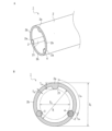
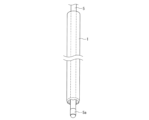
- FIG. 1 is a perspective view of a guide for a medical insertion tool according to one embodiment of the present invention.
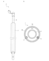
- FIG. 2A is an enlarged view of the proximal end of the medical insertion tool guide shown in FIG. 1
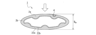
- FIG. 2B is a cross-sectional view of the medical insertion tool guide.
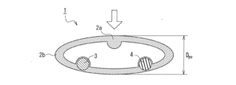
- FIG. 3 is a sectional view showing the medical insertion tool guide shown in FIG. 1 when pressed in the radial direction.
- FIG. 4 is a cross-sectional view of a medical insert guide according to another embodiment of the present invention.
- FIG. 5A is an enlarged view of the proximal end of a medical insert guide according to another embodiment of the present invention
- FIG. 5B is a cross-sectional view of the medical insert guide.
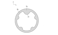
- FIG. 6 is a cross-sectional view of a medical insert guide according to another embodiment of the present invention.
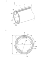
- FIG. 7A is an enlarged view of the proximal end of a medical insert guide according to another embodiment of the present invention
- FIG. 7B is a cross-sectional view of the medical insert guide.
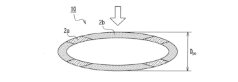
- FIG. 8 is a cross-sectional view showing the state when the medical insertion tool guide shown in FIG. 7 is pressed in the radial direction.
- FIG. 9A is an enlarged view of the proximal end of a medical insert guide according to another embodiment of the present invention
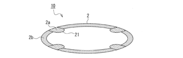
- FIG. 9B is a cross-sectional view of the medical insert guide.
- FIG. 10 is a sectional view showing the medical insertion tool guide shown in FIG. 9 when pressed in the radial direction.
- FIG. 11A is an enlarged view of the proximal end of a medical insert guide according to another embodiment of the present invention
- FIG. 11B is a cross-sectional view of the medical insert guide
- FIG. 12 is a cross-sectional view of a medical insert guide according to another embodiment of the present invention
- FIG. 13A is an enlarged view of the proximal end of a medical insert guide according to another embodiment of the present invention
- FIG. 13B is a cross-sectional view of the medical insert guide.
- FIG. 14 is a perspective view showing a shaft with a camera being inserted into a guide for a medical insertion tool according to one embodiment of the present invention.
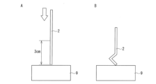
- FIG. 19A is a schematic diagram illustrating the state immediately before measuring the bending strength of the insertion side tip of the cylindrical body
- FIG. 19B is a diagram illustrating how the insertion side tip of the cylindrical body buckles when the bending strength is measured.
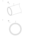
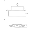
- FIG. FIG. 20A is a schematic diagram illustrating a method for evaluating the compressibility of a cylindrical body
- FIG. 20B is a sectional view showing the state when the cylindrical body is pressed in the radial direction.
- the above-described guide for a medical insertion tool of the present invention includes a cylindrical body that is indwelled in the body.
- the tube is placed in the patient's body from the nose or mouth until it reaches the inside of the esophagus, stomach, duodenum, or jejunum, for example.
- medical insertion devices include feeding catheters that supply nutrients into the body through a nasal tube, a shaft with a camera, and a guide wire.
- the medical insertion tool guide of the present invention is to be indwelled in the body, it is desired that the guide causes less discomfort during indwelling.
- One of the causes of discomfort is the compression of the gastrointestinal tract by the tubular body. Therefore, discomfort during indwelling can be reduced by having the cylindrical body flexible enough to easily deform into a flat shape due to pharyngeal pressure or esophageal pressure, or by forming the cylindrical body into a flat shape in advance.
- a portion of the cylindrical body that is located at least at the same position as the pharynx and upper esophageal sphincter, and a distal end on the insertion side are resistant to pharyngeal pressure or esophageal internal pressure.
- the cross-sectional shape is flexible enough to be deformed into a flat shape, or the cross-sectional shape is already flat.
- the entire length of the cylindrical body in the longitudinal direction has such flexibility that when the cylindrical body is indwelled in the body, the cross-sectional shape is deformed into a flat shape due to pharyngeal pressure or esophageal pressure. Or the cross-sectional shape is flat in advance.
- "deforming into a flat shape” includes a reduction in height (length of the cylindrical body in the pressing direction) and an increase in width (length perpendicular to the pressing direction) due to pressing.
- the cross-sectional shape of the cylindrical body is circular when it is not pressed, it may become elliptical or cocoon-shaped by pressing, or it may become flattened to the extent that the inner cavity of the cylindrical body is almost eliminated.
- the cross-sectional shape of the cylindrical body is circular when it is not pressed, it may become elliptical or cocoon-shaped by pressing, or it may become flattened to the extent that the inner cavity of the cylindrical body is almost eliminated.
- the phrase "previously formed flat” includes, for example, that the cross-sectional shape of the cylindrical body in an unpressed state is an ellipse, a substantially ellipse, or the like. Regardless of whether the cylindrical body has a circular or elliptical cross-sectional shape when not pressed, it is preferable that the cylindrical body deforms easily when pressed from the radial direction, and that the inner wall surface of the pharynx, esophagus, etc. It has enough flexibility to not put pressure on it.
- the cylindrical body of the guide for a medical insertion tool of the present invention has kink resistance from the viewpoint of suppressing displacement of the distal end of the cylindrical body during placement.
- the portion of the cylindrical body that is located at least at the same position as the pharynx and upper esophageal sphincter when indwelled in the body, and the insertion side distal end have kink resistance.
- the cylindrical body has kink resistance over its entire length in the longitudinal direction.
- the cylindrical body extends over its entire length in the longitudinal direction (also referred to as the "axial direction"), and is compressively deformed in the longitudinal direction more than the circumferentially adjacent region (hereinafter also simply referred to as the "adjacent region"). It includes one or more highly kink-resistant regions, for example linear, where kink is unlikely to occur. During indwelling in the body, the adjacent region is bent preferentially due to pressure from the pharynx, esophageal pressure, etc., and the cross-sectional shape of the cylindrical body is deformed into a flattened shape.
- the adjacent region is preferably easily deformable but has low elasticity (weak force to return to its original shape even after bending), and is flexible enough to prevent the deformed cylindrical body from compressing the inner wall surface of the pharynx, esophagus, etc. have sex.
- it is easier to control kink resistance, easy deformability in the radial direction, and flattening than a cylindrical body that has a single kink-resistant property as a whole. More specifically, for example, while a cylindrical body is easily deformed by pressure from the radial direction, it is less flexible than a medical insertion device such as a catheter, and is comparable to a plastic straw made of synthetic resin. Or it has a weaker restoring force.
- the cylindrical body includes a plurality of the high kink-resistant regions.
- the high kink-resistant regions are arranged at predetermined intervals, preferably at equal intervals, along the circumferential direction of the cylindrical body. In this way, when the highly kink-resistant regions are divided into a plurality of regions in the circumferential direction, the molding stability of the cylindrical body is improved.
- the cylindrical body includes a thick portion where the cylindrical wall is relatively thick and a thin portion where the cylindrical wall is relatively thin. .
- the thick portion is a high kink resistance region.
- the configuration in which a highly kink-resistant region is provided by controlling the thickness of the cylindrical wall has the advantage that the cylindrical body can be formed from one type of material.
- the cylindrical body may include a plurality of thick portions and a plurality of thin portions, and the thick portions and thin portions may be alternately arranged along the circumferential direction of the cylindrical body.
- the thickness of the cylindrical body in the thick part is preferably 2 times or more and 5 times or less the thickness of the cylindrical body in the thin part.
- Such an embodiment is suitable for achieving the contradictory functions of being easily deformed by pressure such as pharyngeal pressure or esophageal pressure and having kink resistance.
- the ratio of the thickness of the thin portion of the cylindrical body to the outer diameter of the cylindrical body is preferably 0.10 or less, and preferably 0.08 or less. It is more preferable if it exists, and even more preferably if it is 0.07 or less. Such an embodiment is preferable because the medical insertion tool guide is easily deformed by pressure due to pharyngeal pressure, esophageal pressure, or the like. Note that the lower limit of the ratio (thickness at the thin portion/outer diameter of the cylindrical body) is preferably 0.01 or more from the viewpoint of strength.
- the cylindrical body includes the thick portion by including a protrusion protruding toward the inner cavity.
- a protrusion protruding toward the inner cavity preferably, the cylindrical body includes the thick portion by including a protrusion protruding toward the inner cavity.
- Such a configuration has the advantage of reducing the contact area of the medical insertion tool with the medical insertion tool guide, thereby lowering sliding resistance.
- the surface of the protruding stripes has a curved surface with a high central portion.
- the cylindrical body includes a plurality of the protrusions protruding toward the inner cavity thereof, and an imaginary circle is formed by connecting the tops of the plurality of protrusions.
- This configuration has low sliding resistance of the medical insertion tool against the medical insertion tool guide, and allows smooth insertion and removal of a 3Fr (outer diameter: 1.0 mm) feeding catheter, which is often used in nasal tube feeding therapy. There are advantages to being able to do so.
- the cylindrical body is formed of two or more types of materials having different hardness, and the hardness of the material in the thick part is higher than the hardness of the material in the thin part. It's also expensive. Such a configuration is advantageous in kink resistance, easy deformability in the radial direction, and control of flattening.
- region A and region B are molded from materials with different hardness, selection of the inner diameter and outer diameter of the cylindrical body, the thickness of the cylindrical wall, the circumferential length of the high kink resistant region, etc. It has the advantage of having a high degree of freedom.
- the cylindrical body includes a plurality of regions A and a plurality of regions B, and the regions A and B are arranged alternately along the circumferential direction of the cylindrical body, the molding of the cylindrical body is stabilized. It has good properties and is desirable.
- the above-mentioned hardness is, for example, Shore hardness, which is a value measured using a durometer (type D) in accordance with JIS Z 2246.
- Preferred combinations of the material of region A and the material of region B are, for example, D70/D40 (the former is the material of region A, the latter is the material of region B, the same applies hereinafter), D70/D50, D60/D40, D50/D30. , etc.
- the kink resistance (length) of the cylindrical body evaluated by the loop method is preferably 500 mm or less, more preferably 300 mm or less.
- the above-mentioned kink resistance performance is a value evaluated by the following method.
- [Kink resistance performance evaluation] 1. Mark two places on the surface of the cylindrical body. The distance between the pair of marks shall be 1,000 mm. 2. As shown in FIG. 18, the two marks are overlapped to form a loop with a loop length of 1,000 mm and a loop inner diameter of R. 3. Both ends of the cylindrical body 2 are pulled in the direction of the arrow so that the loop inner diameter R becomes smaller, and the loop length (the length of the cylindrical body 2 forming the loop) at the point where the bend occurs is measured. The loop length is used as an index representing kink resistance performance. It can be said that the smaller the value, the better the kink resistance performance. Note that the distance between the pair of marks may be 600 mm. When the length of the medical insert guide of the present disclosure is shorter than 600 mm, the distance between the pair of marks may be the maximum possible length.
- the bending strength of the insertion side tip of the cylindrical body and its vicinity is preferably 50 g or more, more preferably It is 65g or more.
- the above-mentioned bending strength is measured when the cylindrical body buckles (breaks) when the cylindrical body is held at a position 3 cm from the insertion side tip and the insertion side tip end face is pressed against a balance. This is the weight measured by the balance.
- the bending strength is a parameter representing the degree of ease of bending when the insertion-side distal end is compressed in the longitudinal direction, so the kink resistance of the insertion-side distal end can be evaluated from the bending strength.
- kink resistance cannot be evaluated using the loop method, for example, when there is a highly kink resistant region only in the part located at the same position as the pharynx and upper esophageal sphincter, and in the insertion side tip. Kink resistance can also be easily evaluated. More specifically, the above bending strength is a value evaluated by the following method.
- the ratio of the total circumferential length of the high kink resistant region to the circumferential length of the cylindrical body (100 ⁇ circumferential length of the high kink resistant region ⁇
- the number of highly kink-resistant regions/circumferential length of the cylindrical body varies depending on the material of the cylindrical body, but from the viewpoint of achieving both kink resistance and easy deformability in the radial direction, it is preferably 10 to 80. %, more preferably 15 to 40%.
- the outer diameter of the cylindrical body in the pressing direction is 2.5 mm or less.
- the guide for the medical insertion device of the present invention is placed in a mixed ingestion system, in which nutritional deficiencies are supplemented through nasal tube feeding therapy based on oral ingestion (meals) in which nutrients are ingested through the mouth. It has the advantage that you can do it with less discomfort even if you leave it on. For the same reason, it is preferable that the cylindrical body has such flexibility that when pressed in the radial direction with a pressure of 50 mmHg, it collapses and its inner cavity disappears.
- nasal tube feeding therapy has the advantage of being able to reliably and efficiently supply the necessary nutrients to the patient's stomach.
- the patient's mouth and throat are not used, the patient's swallowing function deteriorates. Therefore, in the medical field, instead of using nasal tube feeding therapy, we first try oral feeding, which is taking nutrients through the mouth.
- oral feeding which is taking nutrients through the mouth.
- patients who have a decreased desire to eat or who have dysphagia easily fall into a state of malnutrition.
- the above-mentioned mixed intake is carried out, for example, while a small feeding catheter with a diameter of about 2.5 mm is indwelled. ing.
- some medical institutions have been conducting the above-mentioned mixed intake with a 6.5 Fr (about 2.15 mm diameter) feeding catheter left in place.
- the application of such mixed intake is limited to patients with reduced throat sensation, such as stroke patients, for example.
- the small-diameter feeding catheter described above is used and is left in place for a certain period of time (for example, two weeks), there is a risk that the catheter will become clogged.
- a preferred embodiment of the guide for a medical insertion device of the present invention is such that when the cylindrical body is pressed in the radial direction with a pressure of 50 mmHg, the outer diameter or thickness of the cylindrical body in the pressing direction is 2.5 mm or less. be.
- the cross-sectional shape of the cylindrical body is formed in advance to be flat, and the outer diameter or thickness of the cylindrical body in an unpressed state is 2.5 mm or less. Therefore, the above-mentioned mixed intake is possible.
- a feeding catheter has a hardness that maintains its internal shape when compressed by the pharynx, esophagus, etc., and a rigidity that does not cause buckling or the like when inserted into the body.
- the cylindrical body constituting the medical insert guide of the present invention is easily deformable but has low elasticity, and preferably the deformed cylindrical body does not press on the inner wall surface of the pharynx, esophagus, etc. It has the flexibility to make it possible.
- the medical insertion device guide of the present invention is placed in place of a feeding catheter, the discomfort during placement is reduced, and oral intake is possible with less discomfort even during placement. Furthermore, since the feeding catheter is inserted into the medical insertion tool guide of the present invention during tube feeding and is removed from the medical insertion tool guide after tube feeding, there is no risk of the feeding catheter becoming clogged. . Therefore, there is an advantage that the degree of freedom in selecting the diameter of the feeding catheter to be used is increased.
- the outer diameter or thickness of the cylindrical body in the pressing direction when the cylindrical body is pressed in the radial direction with a pressure of 150 mmHg is preferably 2.15 mm (equivalent to 6.5 Fr) or less, medical insertion Good oral intake is possible even with the device guide in place.
- the pharyngeal pressure or esophageal pressure during oral ingestion varies depending on the site and varies from person to person, but the highest point is within the range of 50 mmHg to 300 mmHg. Therefore, when the cylindrical body is pressed with a pressure of 50 mmHg (approximately 0.006 N/mm 2 ), the outer diameter or thickness of the cylindrical body in the pressing direction is preferably 2.5 mm or less, more preferably 2.15 mm. If it is below, it can be said that good oral intake is possible even with the medical insertion tool guide left in place.
- the outer diameter or thickness of the cylindrical body in the pressing direction when the cylindrical body is pressed with a pressure of 150 mmHg or 50 mmHg is a value evaluated by the method described in [Compressibility evaluation method] below. .
- FIG. 20A A load cell and an upper compression jig 12 are connected to a tensile testing machine, and a lower compression jig 13 is placed below the upper compression jig. 2. As shown in FIG. 20A, the cylindrical body 2 is set in the gap between the upper compression jig 12 and the lower compression jig 13. 3. The distance S between the upper compression jig 12 and the lower compression jig 13 when the upper compression jig 12 is lowered at a speed of 1 mm/min and pressed with a pressure of 150 mmHg or 50 mmHg, that is, when pressed with a pressure of 150 mmHg or 50 mmHg. The outer diameter Dpo or thickness of the cylindrical body 2 in the pressing direction when the cylindrical body 2 is pressed is measured (FIG. 20B).
- At least one of an optical fiber and a contrast line is preferably embedded within the cylindrical wall of the cylindrical body over the entire length in the longitudinal direction of the cylindrical body. has been done.
- Such a configuration has the advantage that the position of the distal end of the indwelling medical insertion tool guide can be confirmed in a simple manner.
- the medical insertion tool guide 1 has a high kink resistance and a cylindrical body instead of permanently embedding an optical fiber or a contrast line into the cylindrical wall.
- the cylindrical body may include a flexible hard member that can exist independently when removed from the cylindrical wall, and the flexible hard member can be inserted and removed from the cylindrical wall. That is, in one aspect of the medical insert guide of the present invention, the cylindrical body extends in its longitudinal direction, and has high kink resistance where compressive deformation in the longitudinal direction is less likely to occur than in areas adjacent in the circumferential direction.
- the cylindrical body includes two or more regions, the cylindrical body is inserted into and removed from the cylindrical wall along the longitudinal direction, can exist independently when removed from the cylindrical wall, and has kink resistance.
- the flexible hard member including a flexible hard member, one or more of the two or more high kink resistant regions are formed together with the molding of the cylindrical body and are integrated with an adjacent region, and one or more of the The flexible hard member is inserted into and removably into the cylindrical wall along the longitudinal direction.
- the portion of the cylindrical body into which the flexible hard member is inserted is free from the high kink resistance. Functions as a sexual area.
- the number of locations into which the flexible hard member is inserted is one or more fewer than the total number of highly kink-resistant regions of the cylindrical body.
- the cylindrical body has one or more highly kink-resistant regions made of the resin material that constitutes the cylindrical body, such as the thick walled part. As a result, displacement of the distal end of the indwelling cylindrical body is suppressed without increasing discomfort during indwelling.
- a guide for a medical insertion device including a cylindrical body of this embodiment includes the flexible hard member inserted into the cylindrical wall during the insertion operation into the patient's body.
- the flexible hard member By pulling out the flexible hard member from the cylindrical wall after the insertion operation, the number of highly kink-resistant regions in the cylindrical body can be reduced.
- the cylindrical body includes one or more highly kink-resistant regions made of resin material, so that they remain in place. Displacement of the tip of the cylindrical body is suppressed.
- the flexible hard member may be a member containing an optical fiber or a contrast agent, and the flexible hard member is reinserted into the cylinder wall before the patient eats. It may be confirmed that the position of the insertion side tip of the cylindrical body has not shifted by using the cylindrical body.
- the outer diameter of the cylindrical body of the medical insert guide of the present invention is preferably 15.0 mm or less, more preferably 7.0 mm or less, because it facilitates insertion into the nasal cavity and reduces discomfort due to indwelling. It is 3 mm or less.
- the thickness of the cylindrical wall of the cylindrical body of the guide for a medical insertion device of the present invention is determined by the thickness of the cylindrical body due to pharyngeal pressure or esophageal pressure. In order to easily deform and reduce discomfort due to indwelling, it is preferably 0.6 mm or less, more preferably 0.4 mm or less, and from the viewpoint of strength, preferably 0.05 mm or more, more preferably 0.6 mm or less. 075 mm or more. Also from the viewpoint of moldability, the thickness is preferably 0.05 mm or more, more preferably 0.075 mm or more.
- the cylindrical body of the guide for a medical insertion tool of the present invention has an inner cavity of preferably 3 to 16 Fr (outer diameter: 1.0 to 5.3 mm), more preferably 5 to 12 Fr (outer diameter: A feeding catheter (1.7 to 4.0 mm) can be inserted and removed.
- the inner diameter of the cylindrical body in a form where the cylindrical body includes multiple high kinging resistance areas due to the formation of multiple convex lines protruding toward the inner cavity), the tops of the convex lines are tied together.
- the diameter of the imaginary circle is preferably 1.1 mm or more, more preferably 1.8 mm or more, from the viewpoint of a sufficiently fast supply rate of nutrients by tube administration and easy insertion and removal of the nutrition catheter. From the viewpoint of making it possible to set an outer diameter that causes less discomfort during indwelling, it is preferably 14.9 mm or less, more preferably 7.2 mm or less.
- the material of the cylindrical body of the guide for a medical insertion tool of the present invention is not particularly limited, and examples thereof include polyethylene, polyvinyl chloride, polypropylene, polyethylene terephthalate, polytetrafluoroethylene, hexafluoropropylene, vinylidene fluoride, It is at least one selected from polybutadiene, polyurethane, polystyrene thermoplastic elastomer, urethane thermoplastic elastomer, and polyolefin thermoplastic elastomer.
- the cylindrical body is placed inside the patient's body and may come into contact with the patient's body fluids, especially gastric fluids and intestinal fluids, we recommend polyethylene, polypropylene, polybutadiene, polyurethane, etc., which are less susceptible to deterioration (hardening, etc.) even if they come into contact with these fluids. is preferred.
- FIG. 1 is a perspective view of a medical insert guide 1 according to one aspect of the present invention
- FIG. 2A is an enlarged view of the proximal end thereof
- FIG. 2B is a cross-sectional view.
- the medical insertion tool guide 1 includes a cylindrical body 2, and the outer shape of the cross section thereof is circular. As can be clearly seen from FIG. 1, the insertion side tip of the cylindrical body 2 has a rounded surface 2c so as not to damage the digestive tract or the like.
- the cylindrical body 2 is easily deformed by pressure from the radial direction but has low elasticity, so its cross-sectional shape easily deforms into a flat shape due to pharyngeal pressure or esophageal pressure. It has flexibility that allows it not to put pressure on the wall surface. Therefore, there is less discomfort during placement.
- the cylindrical body 2 has an uneven inner surface, and the cylindrical body 2 protrudes toward the inner cavity and extends over the entire length in the longitudinal (length) direction of the cylindrical body 2. It has three protrusions 21 that extend. The protrusions 21 are formed along the circumferential direction of the cylindrical body 2 at predetermined intervals.
- the three protrusions 21 are arranged at predetermined intervals along the circumferential direction, for example, at equal intervals. Therefore, in the cylindrical body 2, thick portions 2a having a relatively thick cylindrical wall and thin portions 2b having a relatively thin cylindrical wall are alternately arranged along the circumferential direction. Since the thick wall portion 2a has a thicker cylindrical wall thickness than the thin wall portion 2b, compressive deformation in the longitudinal direction is relatively less likely to occur than the thin wall portion 2b.
- the thick portion 2a is a highly kink-resistant region 2a in which compressive deformation in the longitudinal direction is less likely to occur than the circumferentially adjacent region (thin portion 2b).
- the adjacent region (thin wall portion 2b) can also be referred to as a low kink resistance region 2b in which compressive deformation in the longitudinal direction is relatively more likely to occur than the thick wall portion 2a.
- the outer diameter D o of the cylindrical body 2 is, for example, 4.8 mm
- the cylindrical body 2 in the thin portion 2b has an outer diameter D o of, for example, 4.8 mm.
- the diameter D i of an imaginary circle connecting the inner surfaces is 4.2 mm
- the diameter D vi of the imaginary circle connecting the tops of the protrusions 21 is 3.2 mm.
- the medical insertion tool guide 1 of this embodiment allows smooth insertion and removal of an 8Fr (outer diameter: 2.7 mm) feeding catheter.
- the thickness T 2a of the cylindrical wall of the cylindrical body 2 in the thick portion 2a (high kink resistance region 2a) is 0.8 mm
- the thickness T 2b of the cylindrical wall of the cylindrical body 2 in the thin portion 2b is 0.3 mm. It is. L 2a is 0.8 mm, and L 2b is 4.2 mm. Therefore, the ratio of the total circumferential length of the highly kink-resistant region 2a to the circumferential length (outer circumferential length) of the cylindrical body 2 is 16%.
- the outer diameter D of the cylindrical body 2 in the pressing direction when the cylindrical body 2 is pressed in the radial direction with a load of 50 mmHg according to the above [compressibility evaluation method] po is 2.5 mm or less, specifically 1.7 mm, and when pressed in the radial direction with a pressure of 150 mmHg, the outer diameter D po of the cylindrical body 2 in the pressing direction is 1.27 mm.
- the bending strength of the insertion side tip of the cylindrical body 2 measured according to the above [Method for evaluating bending strength] is 58.2 g. Therefore, according to the medical insertion tool guide 1 of this embodiment, it is possible to effectively suppress the displacement of the distal end of the indwelling cylindrical body without increasing discomfort during indwelling.
- the kink resistance (loop length) explained using FIG. 18 is preferably 500 mm or less, specifically 30 mm.
- One of the factors that causes the distal end of the indwelled medical insert guide to move from the desired position is the bending of the indwelled medical insert guide in the axial direction. It is particularly likely to occur in the soft palate, which is the part of the body that extends from the mouth to the inside of the digestive tract, from the nasal cavity to the pharynx, which has a large curvature.
- the kink resistance (loop length) is 500 mm or less, bending of the cylindrical body is effectively suppressed.
- the cylindrical body 2 has a highly kink-resistant region 2a that extends over its entire length in the longitudinal direction and is less prone to compressive deformation in the longitudinal direction than adjacent regions. include. Therefore, the cylindrical body 2 is prevented from breaking due to peristaltic movements of organs such as the esophagus or friction with a medical insertion tool such as a nutritional catheter when inserted or removed. Therefore, the possibility that the distal end of the cylindrical body 2, which has been positioned using a camera or the like during indwelling, will greatly retreat from the position is reduced.
- the thin wall portion 2b becomes the thick wall portion 2a (as shown in FIG. 3).
- the cylindrical body 2 is bent with priority over the high kink resistance region 2a), and the cross-sectional shape of the cylindrical body 2 is deformed into a flattened shape.
- the cylindrical body does not press on the inner wall surface of the pharynx, esophagus, etc. during indwelling. Therefore, discomfort during indwelling can be effectively suppressed, and even when the medical insertion tool guide 1 is indwelled, it is possible to take in nutrients orally.
- the contrast line is, for example, a line-shaped thermoplastic resin (eg, polypropylene) containing an X-ray opaque agent such as barium sulfate.
- the optical fiber 3 and the contrast line 4 each reach from the proximal end of the cylindrical body 2 to the distal end.
- the optical fiber 3 and the contrast line 4 can be embedded in the cylindrical body 2 by, for example, a conventionally known method. If light is irradiated onto the proximal end of the optical fiber 3 using a separately prepared light source, the light will propagate to the distal end, so that the distal end of the medical insertion tool guide 1 is placed at the desired position. This can be easily confirmed.
- the contrast line 4 since the contrast line 4 is embedded, it can be confirmed by X-ray photography that the tip of the medical insertion tool guide 1 is placed at a desired position.
- the optical fiber 3 may be inserted into and removed from the cylindrical body 2.
- FIG. 4 shows the optical fiber 3 removed from the cylindrical body 2.
- the medical insert guide 1 can be inserted into a predetermined position in the body and then the optical fiber 3 can be removed from the cylindrical body 2. This is preferable because the number of kink-resistant regions 2a can be reduced and discomfort during placement of the medical insertion tool guide 1 can be reduced.
- the cylindrical body 2 includes three protrusions 21 that protrude toward the inner cavity thereof, and the cylindrical body 2 includes: Although the configuration includes three thick portions 2a (high kink resistance regions) and three thin portions 2b (low kink resistance regions), there is no particular restriction on the number of thick portions 2a and thin portions 2b.
- the cylindrical body 2 may have a configuration including six thick portions 2a and six thin portions 2b. The number of thick portions 2a and thin portions 2b and the ratio of the circumferential length of thick portions 2a and thin portions 2b to the circumferential length of cylindrical body 2 are determined to achieve both kink resistance and ease of flattening deformation.
- the thick portions 2a and the thin portions 2b be arranged at equal intervals along the circumferential direction of the cylindrical body 2, but this is not essential.
- the protrusions 21 may be formed to protrude outward from the cylindrical body 2, and the cylindrical body 2 may have protrusions protruding toward its inner cavity and protruding outwardly.
- the thick portion 2a may be formed by the thick portion 2a.
- the optical fiber 3 and the contrast line 4 may be omitted.
- the surface of the protrusion 21 is a curved surface with a high central part, but it is not limited to this.
- the shape may be semicircular, semielliptical, triangular, trapezoidal, or the like.
- the cross-sectional shapes of all the protrusions do not need to be the same shape or the same size. It may be a combination of more than one species. For example, as shown in FIG. 6, the cross-sectional shape of one of the five protrusions 21 may be larger than the cross-sectional shape of the remaining four protrusions 21.
- FIG. 7A is an enlarged view of the proximal end of the medical insert guide 1 according to one aspect of the present invention
- FIG. 7B is a cross-sectional view.
- the cylindrical body 2 is a tube with a multilayer structure, and the cylindrical body has a first layer 22a and an innermost surface of the cylindrical body 2.
- the contrast line 4 is exposed to the outside of the cylindrical body 2, and the thick part 2a (high kink resistance region) and the thin part 2b (low kink resistance region) are included.
- This guide is the same as the medical insertion tool guide 1 of (Embodiment 1) except that the number of kink-resistant regions is five.
- the first layer 22a is made of a material that can be molded into a tube that is more flexible and exhibits higher kink resistance than the second layer 22b.
- the material is preferably a diene polymer.
- the diene polymer include 1,4-polybutadiene, 1,2-polybutadiene, polyisoprene, thermoplastic polyurethane, polyvinyl chloride, styrene-butadiene block copolymer, and various elastomers. These can be used alone or in a mixture of two or more, but among these, 1,4-polybutadiene or 1,2-polybutadiene is preferred from the viewpoint of flexibility, kink resistance, and moldability. 1,2-polybutadiene is more preferred.
- the second layer 22b is made of a material that has lower sliding resistance to a catheter or the like inserted into and removed from the inner cavity of the cylindrical body 2 than the material of the first layer 22a.
- the material is preferably an olefinic polymer.
- olefin polymers include high density polyethylene (HDPE), linear low density polyethylene (LLDPE), low density polyethylene (LDPE), very low density polyethylene (VLDPE), and ultra-ultra low density polyethylene (ULDPE).
- Examples include polyethylene, ethylene-propylene copolymer, ethylene-vinyl alcohol copolymer, ethylene-methyl (meth)acrylate copolymer, and the like. These can be used alone or in combination of two or more.
- linear low-density polyethylene (LLDPE) and high-density polyethylene (HDPE) can reduce sliding resistance and have high bonding strength with adjacent layers due to their thermal adhesive properties. Examples include one selected type or a mixture thereof.
- the cylindrical body 2 includes a first layer 22a made of a material that is more flexible and exhibits higher kink resistance, and a second layer 22a made of a material that has less sliding resistance against a medical insertion tool. 22b as the innermost layer, it is possible to suppress discomfort during indwelling, suppress displacement of the distal end of the cylindrical body, and facilitate insertion and removal of the medical insertion tool.
- the cylindrical body 2 having such a layered structure can be manufactured using a conventionally known molding technique, for example, by simultaneously extruding the materials of each layer and then cooling.
- the contrast line 4 is exposed outside the cylindrical body 2 and constitutes a part of the outer circumferential surface of the medical insertion tool guide 1; however, the contrast line 4 is not limited to this, and the contrast line 4 shown in FIG. Similarly to the above embodiment, it may be completely embedded inside the cylindrical wall of the cylindrical body 2. Further, the contrast line 4 can be omitted. In that case, a contrast agent may be added to the innermost layer 22b itself.
- the cylindrical body 2 has a two-layer structure including a first layer 22a and a second layer 22b, and the first layer 22a is thicker than the second layer 22b than the innermost layer.
- the thickness of each layer and the number of layers are not limited to these as long as it is flexible, has high kink resistance, and has low sliding resistance against a medical insertion tool.
- the guide 1 for a medical insertion tool of this aspect is an example in which the cylindrical body 2 includes five protrusions 21 that protrude toward the inner cavity of the cylindrical body 2. 2 has a configuration including five thick portions 2a (high kink resistance regions) and five thin portions 2b (low kink resistance regions).
- the material of the first layer 22a is 1,2-polybutadiene, and the material of the second layer 22b is linear low density polyethylene (LLDPE).
- LLDPE linear low density polyethylene
- the outer diameter D o of the cylindrical body 2 is, for example, 5.23 mm
- the diameter D i of an imaginary circle connecting the inner surfaces of the cylindrical body 2 in the thin portion 2b is 4.2 mm.
- the diameter D vi of an imaginary circle connecting the tops of the protrusions 21 is 4.23 mm.
- the medical insertion tool guide 1 of this embodiment allows smooth insertion and removal of an 8Fr (outer diameter: 2.7 mm) feeding catheter.
- the thickness T 2a of the cylindrical wall of the cylindrical body 2 in the thick part 2a is 0.5 mm
- the thickness T 2b of the cylindrical wall of the cylindrical body 2 in the thin part 2b is 0.18 mm.
- L 2a is 0.65 mm
- L 2b is 2.00 mm. Therefore, the ratio of the total circumferential length of the highly kink-resistant region 2a to the circumferential length (outer circumferential length) of the cylindrical body 2 is 25%.
- the outer diameter D po of the cylindrical body 2 in the pressing direction is 2. .5 mm or less, specifically 2.3 mm, and when pressed in the radial direction with a pressure of 150 mmHg, the outer diameter D po of the cylindrical body 2 in the pressing direction is 1.14 mm.
- the bending strength of the insertion side tip of the cylindrical body 2 measured according to the above-mentioned [Bending strength evaluation method] is 75 g. According to the medical insertion tool guide 1 of this embodiment, it is possible to effectively suppress the displacement of the distal end of the cylindrical body being indwelled without increasing discomfort during indwelling.
- the kink resistance (loop length) explained using FIG. 18 is 500 mm or less, specifically 340 mm. Further, even when the tubular body 2 was gripped at both ends in the longitudinal direction and pulled or twisted multiple times, no delamination was observed.
- the cylindrical body 2 extends over its entire length in the longitudinal direction, and compressive deformation in the longitudinal direction is less likely to occur than in the adjacent region. It includes a highly kink resistant region 2a. Therefore, the possibility that the distal end of the cylindrical body 2 positioned within the body will greatly retreat from the position is reduced.
- the thin wall portion 2b becomes the thick wall portion 2a (as shown in FIG. 8).
- the cylindrical body 2 is bent with priority over the high kink resistance region 2a), and the cross-sectional shape of the cylindrical body 2 is deformed into a flattened shape.
- the cylindrical body does not press on the inner wall surface of the pharynx, esophagus, etc. during indwelling. Therefore, discomfort during indwelling can be effectively suppressed, and even when the medical insertion tool guide 1 is indwelled, it is possible to take in nutrients orally.
- FIG. 9A is an enlarged view of the proximal end of the medical insert guide 10 according to one aspect of the present invention
- FIG. 9B is a cross-sectional view.
- the medical insertion tool guide 10 of the present embodiment is different from (Embodiment 1) and (Embodiment 2) in that the cylindrical body 2 is made of two kinds of materials having different hardness arranged alternately in the circumferential direction. It differs from
- the medical insertion tool guide 10 of this embodiment includes a cylindrical body 2, and the outer shape of the cross section thereof is circular. Similar to (Embodiment 1), the cylindrical body 2 is easily deformed by pressure from the radial direction but has low elasticity, so its cross-sectional shape is easily deformed into a flattened shape due to pharyngeal pressure, esophageal pressure, etc. However, it has flexibility that allows it not to put pressure on the inner wall surfaces of the pharynx, esophagus, etc. Therefore, there is less discomfort during placement.
- the cylindrical body 2 has a region A2a formed of a relatively hard material and a region B2b formed of a relatively low hardness material. It differs from the first embodiment in that it includes a plurality of cylinders, which are arranged alternately in the circumferential direction, and the thickness of the cylindrical wall of the cylindrical body 2 is constant in the circumferential direction. Since the region A2a is formed of a material having a relatively higher hardness than the region B2b, compressive deformation in the longitudinal direction is relatively less likely to occur than the region B2b.
- Region A2a is a highly kink-resistant region 2a in which compressive deformation in the longitudinal direction is less likely to occur than in the circumferentially adjacent region (region B2b).
- the adjacent region (region B2b) can also be referred to as a low kink resistance region 2b in which compressive deformation in the longitudinal direction is relatively more likely to occur than in the region A2a.
- the outer diameter D o of the cylindrical body 2 is 4.0 mm, and the inner diameter D i is 3.2 mm.
- the medical insertion tool guide 1 of this embodiment allows smooth insertion and removal of an 8Fr (outer diameter: 2.7 mm) feeding catheter.
- the outer diameter D po of the cylindrical body 2 in the pressing direction is 2. .5 mm or less, and when pressed in the radial direction with a pressure of 150 mmHg, the outer diameter D po of the cylindrical body 2 in the pressing direction is 2.15 mm or less.
- the bending strength of the insertion-side distal end portion explained using FIG. 19 is 440 g or less.
- the kink resistance (loop length) explained using FIG. 18 is 500 mm or less.
- the cylindrical body 2 extends over its entire length in the longitudinal direction, and compressive deformation in the longitudinal direction is less likely to occur than in the adjacent region. It includes a highly kink resistant region 2a. Therefore, the possibility that the distal end of the cylindrical body 2 positioned within the body will greatly retreat from the position is reduced.
- the thickness of the cylindrical wall of the cylindrical body 2 is constant in the circumferential direction, but as shown in FIG.
- the thickness of the cylinder wall in A2a (high kink resistance region 2a) may be thicker than the thickness of the cylinder wall in region B2b.
- Such a configuration is advantageous in kink resistance, easy deformability in the radial direction, and control of flattening.
- the outer diameter Do of the cylindrical body 2 is 4.8 mm
- D i is, for example, 4.0 mm
- D vi is, for example , 3.2 mm. Therefore, the medical insertion tool guide 10 can smoothly insert and remove an 8Fr (outer diameter: 2.7 mm) feeding catheter.
- T 2a is 0.8 mm
- T 2b is 0.4 mm
- L 2a is 0.8 mm
- L 2b is 2.5 mm
- the ratio of the total circumferential length of the high kink-resistant region 2a to the circumferential length (outer circumference length) of the cylindrical body 2 is , 19%.
- the kink resistance (loop length) explained using FIG. 18 is 500 mm or less.
- FIG. 12 is a cross-sectional view of the medical insert guide 10 according to one aspect of the present invention.
- the medical insertion tool guide 10 of this embodiment is the same as the medical insertion tool guide 10 shown in FIG. 11, except that the cylindrical body has an elliptical cross-sectional shape in an unpressed state.
- the thin part 2b bends due to the weight of the thick part 2a even when it is not pressed, and the guide for the medical insertion tool is made to have a flat cross-sectional shape in advance. be able to.
- the cylindrical body may be formed from a single material as in the example shown in FIG. However, it may have a layered structure similar to (Embodiment 2).
- FIG. 13A is an enlarged view of the proximal end of the medical insert guide 100 according to one aspect of the present invention
- FIG. 13B is a cross-sectional view.
- the medical insertion tool guide 100 of this embodiment includes a cylindrical body 2, and the outer shape of the cross section thereof is circular.
- the thickness of the cylindrical wall of the cylindrical body 2 is constant in the circumferential direction. Since the cylindrical body 2 is entirely formed of a single material, it has a single kink resistance characteristic in the circumferential direction, and is different from (Embodiment 1) in this point.
- the outer diameter of the cylindrical body 2 is 4.0 mm, and the thickness of the cylindrical wall is 0.4 mm.
- the medical insertion tool guide 100 of this embodiment allows smooth insertion and removal of an 8Fr (outer diameter: 2.7 mm) feeding catheter.
- the cylindrical body 2 has, for example, kink resistance (length) evaluated by the loop method of 500 mm or less, and is placed in the body and pressed by pharyngeal pressure or esophageal pressure, etc.
- the cross section of the inner cavity is not maintained circular, but is molded from a material that can be easily deformed into a flat cross-sectional shape. Therefore, when the medical insertion tool guide 100 is placed in the body, the fear that the tip of the positioned cylindrical body 2 will move back significantly from the position is reduced, and discomfort during placement is reduced. few.
- the outer diameter of the medical insertion tool inserted into and removed from the inner cavity is equal to the inner diameter of the cylindrical body 2.
- it is preferably 1.7 to 4.0 mm, and specifically, a feeding catheter of 5 to 12 Fr (outer diameter: 1.7 to 4.0 mm) is preferable.
- the cylindrical body 2 of the medical insert guide 100 of this aspect may be formed of a single material, as shown in FIG. 13, or may have a layered structure similar to (Embodiment 2). It may also have the following.
- the cylindrical body includes one or more highly kink-resistant regions along its entire length in the longitudinal direction.
- the cylindrical body may include a highly kink-resistant region in a portion of its entire length in the longitudinal direction.
- the portion of the cylindrical body that is indwelled in the body includes a highly kink-resistant region, while the portion that extends outside the body (see FIG. 15B) includes a highly kink-resistant region. Does not include.
- only the portion 23 of the cylindrical body which is located at the same position as the pharynx and upper esophageal sphincter when it is indwelled in the body, and the insertion side distal end 24, respectively, are (See FIG. 15A).
- the cylindrical body includes a highly kink-resistant region at its insertion-side distal end 24, the cylindrical body is prevented from peristaltic movements of the stomach and intestines, gastroesophageal reflux disease (GERD), etc.
- the insertion side tip 24 means, for example, about 3 to 15 cm from the insertion side tip of the cylindrical body.
- the production of a cylindrical body that includes a highly kink-resistant region in a part of its total length in the longitudinal direction can be performed using conventionally known molding techniques. For example, during one molding process, the molding conditions and material composition may be adjusted appropriately Can be manufactured by changing.
- the cylindrical body 2 has a single-layer structure, but the medical insertion tool guides shown in FIGS. From the viewpoint of reducing sliding resistance against the tool guide, the inner circumferential surface of the cylindrical body may be coated with silicone.
- FIGS. 14 to 17 A method of using the guide for a medical insertion tool of the present invention will be explained using FIGS. 14 to 17.
- An example of how to use the medical insertion tool guide below will be explained using the medical insertion tool guide 1 of (Embodiment 1).
- the camera-equipped shaft 5 is inserted into the inner cavity of the medical insertion tool guide 1.
- the camera-equipped shaft 5 is for carrying the tip of the medical insertion tool guide 1 to a target position. Therefore, although the shaft portion of the camera-equipped shaft 5 is flexible, it is more rigid than the cylindrical body 2 of the medical insertion tool guide 1, and is to the extent that buckling itself does not occur when inserted into the body. It has a rigidity of
- the camera-equipped shaft 5 includes, for example, a camera 5a and an LED light (not shown) at its insertion start side tip.
- the medical insertion tool guide 1, with the camera-equipped shaft 5 inserted into its inner cavity is inserted into the body through the patient's nose.
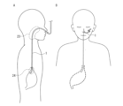
- the shaft 5 with the camera is removed from the medical insertion tool guide 1, and as shown in FIG. 15A, only the medical insertion tool guide 1 is removed. is placed in the body.
- the portion of the medical insertion tool guide 1 that protrudes from the nose to the outside of the body is fixed to the patient's face with tape or the like, as shown in FIG. 15B. In this state, the patient takes breakfast, lunch, and dinner orally.
- the tape is peeled off from the patient, and the feeding catheter 6 is inserted into the lumen from the proximal end of the cylindrical body of the indwelling medical insert guide 1 (see FIGS. 16A and 16A).
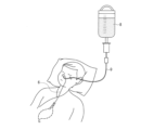
- the proximal end of the feeding catheter 6 and a feeding set including the feeding bottle 8 and the circuit 9 are connected.
- nutrients are supplied to the patient through the feeding catheter 6 by gravity (see FIG. 17).
- the camera-equipped shaft 5 is inserted into the medical insertion tool guide 1 to confirm the position of the tip of the medical insertion tool guide 1. There is also.
- the tip of the feeding catheter 6 comes into contact with the inner circumferential surface of the medical insertion tool guide 1, and While sliding along the circumferential surface, it passes, for example, through the nasal cavity, pharynx, and esophagus in this order. If the medical insert guide 1 is not indwelled in the body, the tip of the feeding catheter 6 will directly collide with the patient's nasal cavity and pharynx. Since the feeding catheter 6 has enough hardness to maintain its internal shape even when compressed by the pharynx or esophagus, a direct collision with its tip causes great pain to the patient.
- the tip of the feeding catheter 6 will not directly collide with the patient's nasal cavity or pharynx. Since it slides on the inner peripheral surface of the body and passes through the nasal cavity, pharynx, and esophagus, the patient's pain is alleviated.
- the cylindrical body has a convex line that protrudes outward from its inner cavity and/or the cylindrical body, since the convex line functions as a cushioning material.
- the feeding catheter 6 is removed from the medical insertion tool guide 1. Then, as shown in FIG. 15B, the portion of the medical insertion tool guide 1 extending outside the body from the nose is fixed to the patient's face with tape or the like. The medical insertion tool guide 1 continues to be left in the body for about two weeks, for example.
- the medical insertion device guide 1 is used together with the feeding catheter 6, it can also be supplied to the market as a medical device 7 for nasal tube feeding therapy including these.
- Cylindrical body 22a First layer 22b Second layer 2a High kink resistance region (thick part, region A) 2b Low kink resistance area (thin wall part, area B) 21 Projection 23 Part of the cylindrical body that is located at the same position as the pharynx and upper esophageal sphincter when indwelled in the body 24 Insertion side tip 3 Optical fiber 4 Contrast line 5 Shaft with camera 6 Nutritional catheter 7 Medical equipment for nasal tube feeding therapy
Landscapes
- Health & Medical Sciences (AREA)
- Life Sciences & Earth Sciences (AREA)
- Animal Behavior & Ethology (AREA)
- Veterinary Medicine (AREA)
- Public Health (AREA)
- General Health & Medical Sciences (AREA)
- Pulmonology (AREA)
- Heart & Thoracic Surgery (AREA)
- Hematology (AREA)
- Biomedical Technology (AREA)
- Anesthesiology (AREA)
- Engineering & Computer Science (AREA)
- Biophysics (AREA)
- Endoscopes (AREA)
Abstract
本発明は、一態様において、鼻又は口から消化管の内部に達するまでの体内に留置され、その内腔に医療用挿入具を挿抜可能とする筒状体(2)を含み、前記筒状体(2)のうちの、前記体内に留置されたときに少なくとも咽頭および食道上部括約筋と同位置に配置される部分(23)及び挿入側先端部(24)について、又は、長手方向全長について、前記筒状体が前記体内に留置されると咽頭圧又は食道内圧で断面形状が扁平に変形するような柔軟性を有するか又は予め断面形状が偏平に形成されており、且つ、耐キンク性を有する、医療用挿入具用ガイド(1)に関する。前記筒状体(2)は、好ましくは、その長手方向全長に渡って延び、周方向に隣接する領域よりも長手方向の圧縮変形が起こりにくい高耐キンク性領域(2a)を1つ以上含む。
Description
本発明は、医療用挿入具用ガイド、およびこれを含む経鼻経管栄養療法用の医療用具等に関する。
急性期で入院している高齢者の低栄養が社会的問題になっている。病院に入院している高齢者の約40%が低栄養であるとの報告もある。低栄養であると、例えば、術後の回復が遅く、医療費や介護費に与える影響も大きい。
鼻から管を通して胃に栄養を投与する経鼻経管栄養療法は、患者の胃に必要な栄養を確実且つ効率的に供給できるという利点がある。しかし、経鼻経管栄養療法では、鼻腔を経て食道を通って胃に栄養物を送るための経鼻栄養カテーテルが、栄養投与時のみならず、非投与時においても、体内に留置されつづける。このカテーテルは、栄養物を送るために必要な大きさの直径と、喉や食道等による圧迫時に内腔形状を維持する硬度を有する。加えて、体内への挿入時に座屈等が生じない程度の剛直性を有する。そのため、このようなカテーテルが喉等に留置され続けることは、患者にとってはかなりの苦痛である。耐えられなくなった患者は、カテーテルを自己抜去してしまうという問題がある。
この問題を解決するために、例えば、特許文献1には、肉厚が非常に薄い外筒とその内部に装着された内筒とを含む内筒使用型消化管チューブが提案されている。当該内筒使用型消化管チューブは、前記外筒に前記内筒を装着した状態で患者に挿入され、薬剤や経管栄養を患者に投与する時以外は内筒が外筒から抜去され、患者には薄い外筒のみが留置される。患者は、経管栄養投与時以外の圧倒的長時間を外筒のみの留置で過ごすことができる。経管栄養投与を行わない時は、外筒の鼻から体外に出ている部分を、折り畳む、結ぶ、或いは捻る等し、患者の顔面にテープで固定する。経管栄養の投与時には、内筒を外筒に再び挿入し、内筒を通じて栄養を投与する。
しかし、特許文献1に開示の外筒は、折り畳む、結ぶ、或いは捻る等ができるほどにその肉厚が非常に薄い。そのため、食道の蠕動運動や、カテーテルの挿抜の際のカテーテル外周との摩擦により、先端が挿入方向の手前に後退し、先端が所望の位置から容易に移動してしまう恐れがある。外筒の先端が所望の位置から移動した状態で外筒をガイドとして内筒(カテーテル)を体内に挿入すると、カテーテルが誤って気管に迷入し、重篤な合併症を引き起こす恐れがある。
そこで、本発明は、一態様において、カテーテル等の医療用挿入具を挿抜可能とし、鼻又は口から消化管の内部に達するまでの体内に留置される医療用挿入具用ガイドに関し、留置時の不快感を増大させることなく、留置された医療用挿入具用ガイドの先端の位置ずれを抑制して、医療用挿入具の安全な挿抜を可能とする、医療用挿入具用ガイドを提供する。
本発明は、一態様において、
鼻又は口から消化管の内部に達するまでの体内に留置され、その内腔に医療用挿入具を挿抜可能とする筒状体を含み、
前記筒状体のうちの、前記体内に留置されたときに少なくとも咽頭および食道上部括約筋と同位置に配置される部分及び挿入側先端部について、又は、長手方向全長について、前記筒状体が前記体内に留置されると咽頭圧又は食道内圧で断面形状が扁平に変形するような柔軟性を有するか又は予め断面形状が偏平に形成されており且つ耐キンク性を有する、医療用挿入具用ガイドに関する。
鼻又は口から消化管の内部に達するまでの体内に留置され、その内腔に医療用挿入具を挿抜可能とする筒状体を含み、
前記筒状体のうちの、前記体内に留置されたときに少なくとも咽頭および食道上部括約筋と同位置に配置される部分及び挿入側先端部について、又は、長手方向全長について、前記筒状体が前記体内に留置されると咽頭圧又は食道内圧で断面形状が扁平に変形するような柔軟性を有するか又は予め断面形状が偏平に形成されており且つ耐キンク性を有する、医療用挿入具用ガイドに関する。
本発明は、一態様において、本発明の医療用挿入具用ガイドと医療用挿入具とを含み、前記医療用挿入具が栄養カテーテルである、経鼻経管栄養療法用の医療用具に関する。
本発明によれば、医療用挿入具用ガイドを構成する筒状体のうちの、前記体内に留置されたときに少なくとも咽頭および食道上部括約筋と同位置に配置される部分及び挿入側先端部について、又は、長手方向全長について、前記筒状体が前記体内に留置されると咽頭圧又は食道内圧で断面形状が扁平に変形するような柔軟性を有するか又は予め断面形状が偏平に形成されており且つ耐キンク性を有するので、留置中の不快感を増大させることなく、留置されている筒状体の先端の位置ずれが抑制される。
故に、本発明の医療用挿入具用ガイドを用いれば、留置中の低不快感と医療用挿入具の安全な挿抜との両立が可能となる。
故に、本発明の医療用挿入具用ガイドを用いれば、留置中の低不快感と医療用挿入具の安全な挿抜との両立が可能となる。
上記の本発明の医療用挿入具用ガイドは、体内に留置される筒状体を含む。筒状体は、患者の鼻又は口から、例えば、食道の内部、胃の内部、十二指腸の内部、又は空腸の内部に達するまでの体内に留置される。医療用挿入具としては、例えば、経鼻により経管的に体内に栄養を補給する栄養カテーテル、カメラ付きシャフト、ガイドワイヤー等が挙げられる。
本発明の医療用挿入具用ガイドは、体内に留置されるものであるため、留置中の不快感が少ないことが望まれる。不快感の原因の一つは、筒状体による消化管の圧迫である。そのため、留置中の不快感は、筒状体を、咽頭圧又は食道内圧等により容易に扁平に変形するような柔軟性を有するか、又は予め扁平に形成すれば、低減できる。
具体的には、一態様において、筒状体のうちの、体内に留置されたときに少なくとも咽頭および食道上部括約筋と同位置に配置される部分及び挿入側先端部は、咽頭圧又は食道内圧で断面形状が扁平に変形するような柔軟性を有するか又は予めその断面形状が偏平である。また、別の一態様において、前記筒状体の長手方向全長について、前記筒状体が前記体内に留置されると咽頭圧又は食道内圧で断面形状が扁平に変形するような柔軟性を有するか又は予め断面形状が偏平である。
具体的には、一態様において、筒状体のうちの、体内に留置されたときに少なくとも咽頭および食道上部括約筋と同位置に配置される部分及び挿入側先端部は、咽頭圧又は食道内圧で断面形状が扁平に変形するような柔軟性を有するか又は予めその断面形状が偏平である。また、別の一態様において、前記筒状体の長手方向全長について、前記筒状体が前記体内に留置されると咽頭圧又は食道内圧で断面形状が扁平に変形するような柔軟性を有するか又は予め断面形状が偏平である。
尚、本発明において「扁平に変形」とは、押圧によって高さ(押圧方向の筒状体の長さ)が小さくなり、幅(押圧方向に直交する長さ)が大きくなること含む。例えば、筒状体の断面形状が押圧されていない状態で円形である場合に、押圧により楕円形や繭型等となり、又は、筒状体の内腔がほぼ無くなる程度に平坦化すること等を含む。また、押圧されていない状態で断面形状が扁平な筒状体が、さらに扁平化することも含む。「予め扁平に形成されており」とは、例えば、押圧されていない状態で筒状体の断面形状が楕円形、略楕円形等であることを含む。筒状体は、押圧されていない状態でその断面形状が円形、楕円形等の何であれ、好ましくは、例えば、径方向からの押圧に対して容易に変形し、咽頭や食道等の内壁面を圧迫しない程度の柔軟性を有する。
また、本発明の医療用挿入具用ガイドの筒状体は、留置中の筒状体の先端の位置ずれを抑制する観点から、耐キンク性を有する。具体的には、一態様において、筒状体のうちの、体内に留置されたときに少なくとも咽頭および食道上部括約筋と同位置に配置される部分及び挿入側先端部は、耐キンク性を有する。また、別の一態様において、前記筒状体は、その長手方向全長に渡って耐キンク性を有する。
好ましくは、筒状体が、その長手方向(「軸方向」とも呼ばれる。)全長に渡って延び、周方向に隣接する領域(以下単に「隣接領域」とも呼ぶ。)よりも長手方向の圧縮変形が起こりにくい、例えば、線状の、高耐キンク性領域を1つ以上含む。体内への留置中は、咽頭圧や食道内圧等による押圧によって隣接領域が優先して屈曲し、筒状体はその断面の外形が扁平に変形する。隣接領域は、好ましくは、易変形でありながら低弾性(曲げても元に戻る力が弱い)であり、変形した筒状体が咽頭や食道等の内壁面を圧迫しないことを可能とする柔軟性を有する。かかる構成は、全体が単一の耐キンク特性を有する筒状体よりも、耐キンク性、径方向への易変形性および扁平化の制御が行い易い。より具体的には、例えば、筒状体は、径方向からの押圧に対して易変形である反面、カテーテル等の医療用挿入具よりも可撓性が低く、例えば、合成樹脂製のストロー程度若しくはそれよりも弱い復元力を有する。
好ましくは、筒状体が、その長手方向(「軸方向」とも呼ばれる。)全長に渡って延び、周方向に隣接する領域(以下単に「隣接領域」とも呼ぶ。)よりも長手方向の圧縮変形が起こりにくい、例えば、線状の、高耐キンク性領域を1つ以上含む。体内への留置中は、咽頭圧や食道内圧等による押圧によって隣接領域が優先して屈曲し、筒状体はその断面の外形が扁平に変形する。隣接領域は、好ましくは、易変形でありながら低弾性(曲げても元に戻る力が弱い)であり、変形した筒状体が咽頭や食道等の内壁面を圧迫しないことを可能とする柔軟性を有する。かかる構成は、全体が単一の耐キンク特性を有する筒状体よりも、耐キンク性、径方向への易変形性および扁平化の制御が行い易い。より具体的には、例えば、筒状体は、径方向からの押圧に対して易変形である反面、カテーテル等の医療用挿入具よりも可撓性が低く、例えば、合成樹脂製のストロー程度若しくはそれよりも弱い復元力を有する。
上記の本発明の医療用挿入具用ガイドにおいて、好ましくは、筒状体が複数の前記高耐キンク性領域を含む。そして、高耐キンク性領域が、筒状体の周方向に沿って所定の間隔、好ましくは、等間隔で配置されている。このように、高耐キンク性領域が、周方向に複数に分割配置されていると、筒状体の成形安定性が良い。
上記の本発明の医療用挿入具用ガイドにおいて、好ましくは、筒状体が、その筒壁の厚みが相対的に厚い肉厚部と、筒壁の厚みが相対的に薄い肉薄部とを含む。当該肉厚部が、高耐キンク性領域である。このように、筒壁の厚さを制御することにより高耐キンク性領域を設ける構成では、1種の材料で筒状体を形成できるという利点がある。かかる構成では、筒状体が、肉厚部と肉薄部とを各々複数含み、筒状体の周方向に沿って肉厚部と肉薄部とが交互に配置されていてもよい。
肉厚部における筒状体の厚みは、肉薄部における筒状体の厚みに対して2倍以上5倍以下が好ましい。かかる態様は、咽頭圧又は食道内圧等による押圧により容易に変形し且つ耐キンク性を持つという、相反する機能を両立させるのに好適である。
前記筒状体の外径に対する前記筒状体の前記肉薄部における厚みの比(前記肉薄部における厚み/筒状体の外径)が、0.10以下であると好ましく、0.08以下であるとより好ましく、0,07以下であるとさらに好ましい。かかる態様であれば、医療用挿入具用ガイドが、咽頭圧又は食道内圧等による押圧により容易に変形し、好ましい。尚、前記比(前記肉薄部における厚み/筒状体の外径)の下限は、強度の観点から0.01以上が好ましい。
上記の本発明の医療用挿入具用ガイドにおいて、好ましくは、筒状体が、その内腔に向かって突出した凸条を含むことにより、上記肉厚部を含む。かかる構成は、医療用挿入具の医療用挿入具用ガイドに対する接触面積を減らして摺動抵抗を下げることができる利点がある。同様の理由から、より好ましくは、肉厚部と肉薄部とを各々複数含み、筒状体の周方向に沿って肉厚部と肉薄部とが交互に配置される。また、同様の理由から、凸条の表面は、中央部が高い曲面であると好ましい。
上記の本発明の医療用挿入具用ガイドにおいて、好ましくは、筒状体が、その外方に向かって突出した凸条を含むことにより、上記肉厚部を含む。かかる構成によれば、筒状体と患者体内との接触面積を減らすことで、患者の体内に医療用挿入具用ガイドを留置する際の摺動抵抗を下げることができる。尚、上記の本発明の医療用挿入具用ガイドにおいて、筒状体は、その内腔に向かって突出した凸条と、その外方に向かって突出した凸部の両方を含み、それらが上記肉厚部を構成していてもよい。
上記の本発明の医療用挿入具用ガイドにおいて、好ましくは、前記筒状体がその内腔に向かって突出した複数の前記凸条を含み、複数の前記凸条の頂部を結んだ仮想の円の直径が、1.0mm以上である。かかる構成は、医療用挿入具の医療用挿入具用ガイドに対する摺動抵抗が低く、経鼻経管栄養療法において多用されている3Fr(外径:1.0mm)の栄養カテーテルの挿抜がスムーズに行える利点がある。
上記の本発明の医療用挿入具用ガイドにおいて、好ましくは、筒状体は、硬さの異なる2種以上の材料で形成され、肉厚部の材料の硬度が、肉薄部の材料の硬度よりも高い。かかる構成では、耐キンク性、径方向への易変形性および扁平化の制御において有利である。
上記の本発明の医療用挿入具用ガイドにおいて、好ましくは、筒状体の筒壁が、領域Bと、前記領域Bに隣接し前記領域Bの材料よりも高硬度の材料で形成された領域Aと、を含む。当該領域Aが、前記高耐キンク性領域である。領域Bと領域Aは、筒状体の周方向に沿って隣接している。このように、硬度が相対的に高い材料を用いて高耐キンク性領域を設ける構成では、例えば、筒状体の筒壁の厚みを周方向に一定とすることも可能である。このように、領域Aと領域Bが、硬度の異なる材料にて成形される場合、筒状体の内径、外径、筒壁の厚さ、高耐キンク性領域の周方向長さ等の選択の自由度が高いという利点がある。かかる構成では、筒状体が、領域Aと領域Bとを各々複数含み、筒状体の周方向に沿って領域Aと領域Bとが交互に配置されていると、筒状体の成形安定性が良く、好ましい。
上記硬度は、例えば、ショア硬度であり、JIS Z 2246に準拠して、デュロメーター(タイプD)を用いて測定される値である。領域Aの材料と領域Bの材料の、好ましい組み合わせは、例えば、D70/D40(前者が領域Aの材料、後者が領域Bの材料、以下同じ)、D70/D50、D60/D40、D50/D30、等が挙げられる。
上記の本発明の医療用挿入具用ガイドにおいて、筒状体の、ループ法により評価される耐キンク性能(長さ)が、好ましくは500mm以下、より好ましくは300mm以下である。尚、本発明において、上記耐キンク性能は、下記の方法により評価した値である。
[耐キンク性能評価]
1.筒状体の表面の2箇所に目印をつける。当該1対の目印間の距離は1,000mmとする。
2.図18に示すように、前記2つの目印を重ね合わせ、ループ長が1,000mm、ループ内径がRのループをつくる。
3. 筒状体2の両端を、ループ内径Rが小さくなるように、各々矢印の方向に引張り、折れが生じた時点におけるループ長(ループを形成する筒状体2の長さ)を測定し、当該ループ長を、耐キンク性能を表す指標とする。
値が小さいほど耐キンク性能が優れていると言える。
尚、1対の目印間の距離は600mmであってもよい。本開示の医療用挿入具用ガイドの長さが600mmよりも短い場合、1対の目印間の距離は取り得る最大の長さとすればよい。
1.筒状体の表面の2箇所に目印をつける。当該1対の目印間の距離は1,000mmとする。
2.図18に示すように、前記2つの目印を重ね合わせ、ループ長が1,000mm、ループ内径がRのループをつくる。
3. 筒状体2の両端を、ループ内径Rが小さくなるように、各々矢印の方向に引張り、折れが生じた時点におけるループ長(ループを形成する筒状体2の長さ)を測定し、当該ループ長を、耐キンク性能を表す指標とする。
値が小さいほど耐キンク性能が優れていると言える。
尚、1対の目印間の距離は600mmであってもよい。本開示の医療用挿入具用ガイドの長さが600mmよりも短い場合、1対の目印間の距離は取り得る最大の長さとすればよい。
上記の本発明の医療用挿入具用ガイドにおいて、前記筒状体の挿入側先端およびその近傍部分(「挿入側先端部」とも言う)の曲げ強度は、好ましくは50g以上であり、より好ましくは65g以上である。
本発明において、上記曲げ強度は、筒状体の挿入側先端から3cmの箇所を把持した状態で前記挿入側先端端面を天秤に押し当て、前記筒状体が座屈した(折れた)時点で前記天秤により計測される重量である。上記曲げ強度は、前記挿入側先端部を長手方向に圧縮させたときの折れ易さの程度を表すパラメーターであることから、前記曲げ強度から挿入側先端部の耐キンク性を評価できる。
この方法によれば、例えば、咽頭および食道上部括約筋と同位置に配置される部分と挿入側先端部のみに高耐キンク性領域がある場合のようにループ法では耐キンク性の評価ができない態様に対しても、簡便に耐キンク性の評価が行える。
上記曲げ強度は、より具体的には、下記の方法により評価した値である。
本発明において、上記曲げ強度は、筒状体の挿入側先端から3cmの箇所を把持した状態で前記挿入側先端端面を天秤に押し当て、前記筒状体が座屈した(折れた)時点で前記天秤により計測される重量である。上記曲げ強度は、前記挿入側先端部を長手方向に圧縮させたときの折れ易さの程度を表すパラメーターであることから、前記曲げ強度から挿入側先端部の耐キンク性を評価できる。
この方法によれば、例えば、咽頭および食道上部括約筋と同位置に配置される部分と挿入側先端部のみに高耐キンク性領域がある場合のようにループ法では耐キンク性の評価ができない態様に対しても、簡便に耐キンク性の評価が行える。
上記曲げ強度は、より具体的には、下記の方法により評価した値である。
[曲げ強度の評価方法]
1.図19に示すように、筒状体2の挿入側先端から3cmの箇所を把持する。
2.把持した箇所から先端までの筒状体2の軸が電子天秤に対して垂直になるように把持したまま電子天秤9に筒状体2の挿入側先端を押し付け、重量を計測する。
3.電子天秤9に筒状体2の挿入側先端を押し付けて座屈した時点で測定を終了する。
4.重量の最大値を記録する。
1.図19に示すように、筒状体2の挿入側先端から3cmの箇所を把持する。
2.把持した箇所から先端までの筒状体2の軸が電子天秤に対して垂直になるように把持したまま電子天秤9に筒状体2の挿入側先端を押し付け、重量を計測する。
3.電子天秤9に筒状体2の挿入側先端を押し付けて座屈した時点で測定を終了する。
4.重量の最大値を記録する。
[曲げ強度の評価方法]により計測される「重量の最大値」が、上記曲げ強度である。筒状体の曲げ強度が、留置中の先端の位置ずれの問題が生じない既存の栄養カテーテル(6Fr(外径2.0mm))の曲げ強度と同程度かそれ以上であれば、留置されている筒状体の先端の位置ずれが効果的に抑制される。ただし、筒状体の曲げ強度が大きすぎると、体内への挿入操作最中の患者の不快感が大きくなるため、当該曲げ強度は、440g以下が好ましく、380g以下がより好ましい。尚、これらの曲げ強度の上限値は、生体に影響を与えないという理由から、12Frのガイドワイヤーが内腔に挿入された栄養カテーテルの曲げ強度(440g)よりも小さい値である。
上記の本発明の医療用挿入具用ガイドにおいて、筒状体の周方向長に対する、高耐キンク性領域の周方向長さの合計の割合(100×高耐キンク性領域の周方向長さ×高耐キンク性領域の数/筒状体の周方向長)は、筒状体の材料によって異なるが、耐キンク性と径方向への易変形性との両立の観点から、好ましくは10~80%であり、より好ましくは15~40%である。
上記の本発明の医療用挿入具用ガイドにおいて、好ましくは、筒状体を50mmHgの圧力で径方向に押圧した時の筒状体の押圧方向の外径が2.5mm以下である。かかる構成では、口から栄養を摂取する経口摂取(食事)を基本とし、栄養の不足分を経鼻経管栄養療法にて補充するという混合摂取を、本発明の医療用挿入具用ガイドを留置したままでも、少ない不快感で行えるという利点がある。同様の理由から、筒状体は、50mmHgの圧力で径方向に押圧すると潰れてその内腔が無くなる程度の柔軟性を有していると好ましい。尚、筒状体2が径方向に押圧され、潰れて内腔が無くなる場合、上記「筒状体の押圧方向の外径」は「筒状体の押圧方向の厚み」と読みかえることとする。
より詳細に説明すると、上記の通り、経鼻経管栄養療法は、患者の胃に必要な栄養を確実且つ効率的に供給できるという利点がある。しかし、口や喉を使用しないことから、患者の嚥下機能を低下させてしまう。そのため、医療現場では、まずは、経鼻経管栄養療法ではなく、口から栄養を摂取する経口摂取を試みる。しかし、食べる意欲が低下した患者や、嚥下障害を有する患者は、容易に低栄養状態に陥ってしまう。
そのため、医療現場では、患者の経口摂取時の不快感を軽減しつつ、低栄養状態を防ぐために、例えば、直径2.5mm程度の細径の栄養カテーテルを留置した状態で、上記混合摂取を行っている。また、近年、6.5Fr(直径2.15mm程度)の栄養カテーテルを留置した状態で上記混合摂取を行っている医療機関もある。しかし、このような混合摂取の適用は、例えば、脳卒中患者等の喉の感覚が低下した患者に限定される。また、上記細径の栄養カテーテルが使用され、しかも一定期間(例えば、2週間)留置されるので、カテーテルが詰まるリスクがある。
本発明の医療用挿入具用ガイドの好ましい態様は、上記の通り、筒状体を50mmHgの圧力で径方向に押圧した時の筒状体の押圧方向の外径又は厚みが2.5mm以下である。或いは、筒状体の断面形状が予め偏平に形成され、押圧されていない状態でその外径又は厚みが2.5mm以下である。そのため、上記混合摂取が可能である。栄養カテーテルは、咽頭や食道等による圧迫時にその内腔形状を維持する硬度を有し、体内への挿入時に座屈等が生じない程度の剛直性を有するものである。これに対し、本発明の医療用挿入具用ガイドを構成する筒状体は、易変形でありながら低弾性であり、好ましくは、変形した筒状体が咽頭や食道等の内壁面を圧迫しないことを可能とする柔軟性を有する。
そのため、栄養カテーテルに替えて本発明の医療用挿入具用ガイドを留置すれば、留置中の不快感が低減され、留置中でも少ない不快感で経口摂取が可能である。また、栄養カテーテルは、経管栄養投与時に本発明の医療用挿入具用ガイド内に挿入され、経管投与が終わると医療用挿入具用ガイドから抜き取られるため、栄養カテーテルが詰まるというリスクもない。そのため、使用する栄養カテーテルの径の選択の自由度が高くなるという利点もある。
一方で、“頸部食道切除および喉頭切除後に上部食道括約筋機能の低下をみた3症例” 日臨外医会誌51(4),699-703,1990 大阪市立大学第2外科(主任:木下博明教授) 徳原太豪他(https://www.jstage.jst.go.jp/article/ringe1963/51/4/51_4_699/_pdf/-char/en)によれば、消化器内の最大閉圧力は、食道上部括約筋による圧力であり、0.020N/mm2(約150mmHg)である。したがって、筒状体を、150mmHgの圧力で径方向に押圧した時の筒状体の押圧方向の外径又は厚みが、好ましくは2.15mm(6.5Fr相当)以下であれば、医療用挿入具用ガイドを留置したままでも良好な経口摂取が可能である。
また、経口摂取最中の咽頭圧又は食道内圧は、部位によって異なり個人差もあるが、最も高い箇所で50mmHg~300mmHgの範囲内の値である。したがって、筒状体を、50mmHg(約0.006N/mm2)の圧力で押圧した時の筒状体の押圧方向の外径又は厚みが、好ましくは2.5mm以下、より好ましくは2.15mm以下であれば、医療用挿入具用ガイドを留置したままでも良好な経口摂取が可能であると言える。
筒状体を150mmHg又は50mmHgの圧力で押圧した時の筒状体の押圧方向の外径又は厚みは、具体的には、下記[圧縮性の評価方法]に記載の方法により評価した値である。
[圧縮性の評価方法]
1.引張試験機にロードセルと上側圧縮治具12とを接続し、上側圧縮治具の下側に下側圧縮治具13を配置する。
2.図20Aに示されるように、上側圧縮治具12と下側圧縮治具13の隙間に筒状体2をセットする。
3.速度1mm/minで上側圧縮治具12を降下させ、150mmHg又は50mmHgの圧力で押圧した時の上側圧縮治具12と下側圧縮治具13の距離S、即ち、150mmHg又は50mmHgの圧力で押圧された時の筒状体2の押圧方向の外径Dpo又は厚みを、各々、計測する(図20B)。
1.引張試験機にロードセルと上側圧縮治具12とを接続し、上側圧縮治具の下側に下側圧縮治具13を配置する。
2.図20Aに示されるように、上側圧縮治具12と下側圧縮治具13の隙間に筒状体2をセットする。
3.速度1mm/minで上側圧縮治具12を降下させ、150mmHg又は50mmHgの圧力で押圧した時の上側圧縮治具12と下側圧縮治具13の距離S、即ち、150mmHg又は50mmHgの圧力で押圧された時の筒状体2の押圧方向の外径Dpo又は厚みを、各々、計測する(図20B)。
上記の本発明の医療用挿入具用ガイドにおいて、好ましくは、筒状体の筒壁内に、前記筒状体の長手方向全長に渡って、光ファイバーおよび造影ラインのうちの少なくとも1方が埋入されている。かかる構成は、留置された医療用挿入具用ガイドの先端の位置確認が、簡便な方法で行えるという利点がある。
また、本発明の一態様にかかる医療用挿入具用ガイド1は、光ファイバーや造影ラインを筒壁内へ恒久的に埋入することに代えて、それ自体の耐キンク性が高く、筒状体の筒壁から抜去されたときに独立して存在できる、可撓性硬質部材を筒状体が備え、当該可撓性硬質部材を前記筒壁から挿抜可能とする構成としてもよい。
即ち、本発明の医療用挿入具用ガイドは、一態様において、筒状体が、その長手方向に渡って延び、周方向に隣接する領域よりも長手方向の圧縮変形が起こりにくい高耐キンク性領域を2つ以上含み、前記筒状体は、その筒壁内に長手方向に沿って挿抜可能に挿入され、前記筒壁から抜去されたときに独立して存在でき、耐キンク性を有する可撓性硬質部材を含み、2つ以上の前記高耐キンク性領域のうちの、1つ以上は、前記筒状体の成形とともに形成されて隣接する領域と一体化しており、1つ以上は、前記筒壁内に長手方向に沿って挿抜可能に挿入された前記可撓性硬質部材を含む。本態様では、前記可撓性硬質部材が前記筒状体の筒壁内に挿入された状態で、前記筒状体のうちの前記可撓性硬質部材が挿入された箇所が、前記高耐キンク性領域として機能する。
尚、本態様では、前記可撓性硬質部材が挿入された箇所は前記筒状体の高耐キンク性領域の総数よりも1つ以上少ない。従って、全ての前記可撓性硬質部材を抜去した後でも、前記筒状体は、例えば、上記肉厚部のように筒状体を構成する樹脂材料からなる1つ以上の高耐キンク性領域を持つこととなり、留置中の不快感を増大させることなく、留置されている筒状体の先端の位置ずれが抑制される。
即ち、本発明の医療用挿入具用ガイドは、一態様において、筒状体が、その長手方向に渡って延び、周方向に隣接する領域よりも長手方向の圧縮変形が起こりにくい高耐キンク性領域を2つ以上含み、前記筒状体は、その筒壁内に長手方向に沿って挿抜可能に挿入され、前記筒壁から抜去されたときに独立して存在でき、耐キンク性を有する可撓性硬質部材を含み、2つ以上の前記高耐キンク性領域のうちの、1つ以上は、前記筒状体の成形とともに形成されて隣接する領域と一体化しており、1つ以上は、前記筒壁内に長手方向に沿って挿抜可能に挿入された前記可撓性硬質部材を含む。本態様では、前記可撓性硬質部材が前記筒状体の筒壁内に挿入された状態で、前記筒状体のうちの前記可撓性硬質部材が挿入された箇所が、前記高耐キンク性領域として機能する。
尚、本態様では、前記可撓性硬質部材が挿入された箇所は前記筒状体の高耐キンク性領域の総数よりも1つ以上少ない。従って、全ての前記可撓性硬質部材を抜去した後でも、前記筒状体は、例えば、上記肉厚部のように筒状体を構成する樹脂材料からなる1つ以上の高耐キンク性領域を持つこととなり、留置中の不快感を増大させることなく、留置されている筒状体の先端の位置ずれが抑制される。
このように、当該筒状体のうちの当該可撓性硬質部材が挿入された箇所を、高耐キンク性領域とし、当該可撓性硬質部材が、筒状体の筒壁内に対して挿抜可能である態様では、医療用挿入具用ガイドの留置中の不快感がより一層少なくなり、好ましい。
具体的には、このような態様の筒状体を含む医療用挿入具用ガイドは、患者の体内への挿入操作中は前記筒壁内に対して挿入された前記可撓性硬質部材を含み、挿入操作後、前記可撓性硬質部材を筒壁から抜くことで、前記筒状体における高耐キンク性領域の数を減らすことができる。また、全ての前記可撓性硬質部材を前記筒壁から抜いた後も、上記の通り、前記筒状体には樹脂材料からなる高耐キンク性領域が1つ以上含まれるので、留置されている筒状体の先端の位置ずれが抑制される。
具体的には、このような態様の筒状体を含む医療用挿入具用ガイドは、患者の体内への挿入操作中は前記筒壁内に対して挿入された前記可撓性硬質部材を含み、挿入操作後、前記可撓性硬質部材を筒壁から抜くことで、前記筒状体における高耐キンク性領域の数を減らすことができる。また、全ての前記可撓性硬質部材を前記筒壁から抜いた後も、上記の通り、前記筒状体には樹脂材料からなる高耐キンク性領域が1つ以上含まれるので、留置されている筒状体の先端の位置ずれが抑制される。
前記可撓性硬質部材は光ファイバーや造影剤を含む部材であっても良く、患者の食事を行う前に前記筒壁内に前記可撓性硬質部材を再挿入し、前記可撓性硬質部材を用いて筒状体の挿入側先端の位置ずれが起こっていないことを確認しても良い。
上記の本発明の医療用挿入具用ガイドの筒状体の外径は、鼻腔への挿入が行い易く、留置による不快感を減らすという理由から、好ましくは15.0mm以下、より好ましくは7.3mm以下である。筒状体2の外径は、その下限について特に制限はないが、栄養カテーテルを容易に挿抜できる内径の設定を可能とする観点から、好ましくは1.2mm以上、より好ましくは1.9mm以上、更に好ましくは2.9mm以上である。
上記の本発明の医療用挿入具用ガイドの筒状体の筒壁(肉厚部を高耐キンク性領域とする形態では肉薄部)の厚さは、咽頭圧又は食道内圧により筒状体が変形し易く、留置による不快感を減らすという理由から、好ましくは0.6mm以下であり、より好ましくは0.4mm以下であり、強度の観点から、好ましくは0.05mm以上、より好ましくは0.075mm以上である。成形性の観点でも、好ましくは0.05mm以上、より好ましくは0.075mm以上である。
上記の本発明の医療用挿入具用ガイドの筒状体は、その内腔に、好ましくは3~16Fr(外径:1.0~5.3mm)、より好ましくは5~12Fr(外径:1.7~4.0mm)の栄養カテーテルを挿抜可能である。また、筒状体の内径(筒状体が、その内腔に向かって突出した凸条が複数形成されることにより、複数の高耐キング性領域を含む形態では、凸条の頂部を結んだ仮想の円の直径)は、経管投与による栄養物の十分に速い供給速度、および栄養カテーテルの挿抜を容易に行う観点から、好ましくは1.1mm以上、より好ましくは1.8mm以上であり、留置による不快感が少ない外径の設定を可能とする観点から、好ましくは14.9mm以下、より好ましくは7.2mm以下である。
上記の本発明の医療用挿入具用ガイドの筒状体の材料は、特に限定されないが、例えば、ポリエチレン、ポリ塩化ビニル、ポリプロピレン、ポリエチレンテレフタレート、ポリテトラフルオロエチレン、ヘキサフルオロプロピレン、ビニリデンフロライド、ポリブタジエン、ポリウレタン、ポリスチレン系熱可塑性エラストマー、ウレタン系熱可塑性エラストマーおよびポリオレフィン系熱可塑性エラストマーから選ばれる少なくとも1種である。筒状体は患者体内に留置され、患者の体液、特に胃液や腸液に接触する可能性のあることから、それらの体液に触れても変質(硬化等)の少ないポリエチレン、ポリプロピレン、ポリブタジエン、ポリウレタン等が好ましい。
以下に、本発明を好適な実施形態を示しながら詳細に説明する。但し、本発明は以下の実施形態に限定されない。
(実施形態1)
図1は、本発明の一態様にかかる医療用挿入具用ガイド1の斜視図であり、図2Aは、その基端側端部の拡大図であり、図2Bは、断面図である。
図1は、本発明の一態様にかかる医療用挿入具用ガイド1の斜視図であり、図2Aは、その基端側端部の拡大図であり、図2Bは、断面図である。
医療用挿入具用ガイド1は、筒状体2を含み、その断面の外形は円形である。図1から良く分かるように、筒状体2の挿入側先端は、消化管等を傷つけないようにアール面2cを有する。筒状体2は、径方向からの押圧に対して易変形でありながら低弾性であるので、咽頭圧又は食道内圧等によりその断面形状が容易に扁平に変形するが、咽頭や食道等の内壁面を圧迫しないことを可能とする柔軟性を有する。故に、留置中の不快感が少ない。
筒状体2は、その断面からよく分かるように、その内面は凹凸面であり、筒状体2は、その内腔に向かって突出し、筒状体2の長手(長さ)方向全長に渡って延びた、3つの凸条21を有する。凸条21は、筒状体2の周方向に沿って所定の間隔をあけて形成されている。
筒状体2では、3つの凸条21が、周方向に沿って所定の間隔をあけ、例えば、等間隔に配置されている。そのため、筒状体2は、相対的に筒壁の厚さが厚い肉厚部2aと相対的に筒壁の厚さが薄い肉薄部2bとが周方向に沿って交互に配置されている。肉厚部2aは、肉薄部2bよりも筒壁の厚さが厚いため、相対的に肉薄部2bよりもより長手方向の圧縮変形が起こりにくい。肉厚部2aは、周方向に隣接する領域(肉薄部2b)よりも長手方向の圧縮変形が起こりにくい高耐キンク性領域2aである。隣接領域(肉薄部2b)は、相対的に肉厚部2aよりもより長手方向の圧縮変形が起こり易い低耐キンク性領域2bということもできる。
本態様の医療用挿入具用ガイド1は一例において、図2Bに示されるように、筒状体2の外径Doは、例えば、4.8mmであり、肉薄部2bにおける筒状体2の内面を結んだ仮想の円の直径Diは、4.2mmであり、凸条21の頂部を結んだ仮想の円の直径Dviは、3.2mmである。本態様の医療用挿入具用ガイド1は、8Fr(外径:2.7mm)の栄養カテーテルの挿抜がスムーズに行える。
肉厚部2a(高耐キンク性領域2a)における筒状体2の筒壁の厚みT2aは、0.8mm、肉薄部2bにおける筒状体2の筒壁の厚みT2bは、0.3mmである。L2aは、0.8mm、L2bは、4.2mmである。故に、筒状体2の周方向長(外周長)に対する、高耐キンク性領域2aの周方向長の合計の割合は、16%である。
図3及び図20に示されるように、上記[圧縮性の評価方法]に従って、筒状体2を、50mmHgの荷重で径方向に押圧した時の、筒状体2の押圧方向の外径Dpoは2.5mm以下、具体的には1.7mmであり、150mmHgの圧力で径方向に押圧した時の、筒状体2の押圧方向の外径Dpoは1.27mmである。また、上記[曲げ強度の評価方法]に従って測定された筒状体2の挿入側先端部の曲げ強度は58.2gである。そのため、本態様の医療用挿入具用ガイド1によれば、留置中の不快感を増大させることなく、留置されている筒状体の先端の位置ずれが効果的に抑制できる。
図18を用いて説明した、耐キンク性能(ループ長)は、好ましくは500mm以下であり、具体的には30mmである。留置された医療用挿入具用ガイドの先端の所望の位置からの移動の要因として、留置された医療用挿入具用ガイドの軸方向の折れが挙げられ、当該筒状体の折れは、鼻又は口から消化管の内部に達するまでの体内のうち、屈曲が大きい鼻腔から咽頭まで、特に、軟口蓋部で起こりやすい。耐キンク性能(ループ長)が500mm以下であると、筒状体の折れが効果的に抑制される。
本発明の一態様にかかる医療用挿入具用ガイド1では、筒状体2が、その長手方向全長に渡って延び、隣接領域よりも長手方向の圧縮変形が起こりにくい高耐キンク性領域2aを含む。そのため、食道等の臓器の蠕動運動や、栄養カテーテル等の医療用挿入具の挿入又は抜去に伴う医療用挿入具との摩擦等によって、筒状体2が、折れることが抑制される。そのため、留置の際にカメラ等を用いて位置決めされた筒状体2の先端が、当該位置から大きく後退する恐れが低減される。
加えて、咽頭圧や食道内圧を想定した押圧力が、医療用挿入具用ガイド1の径方向に加わった際には、図3に示されるように、肉薄部2bが、肉厚部2a(高耐キンク性領域2a)よりも優先して屈曲し、筒状体2はその断面の外形が扁平に変形する。そして、筒状体は、留置中、咽頭や食道等の内壁面を圧迫しない。そのため、留置中の不快感を効果的に抑えることができ、医療用挿入具用ガイド1を留置した状態でも、経口からの栄養の摂取が可能となる。
筒状体2の肉厚部2a(高耐キンク性領域2a)内には、光ファイバー3及び造影ライン4が埋入されている。造影ラインとしては、例えば、硫酸バリウムのX線不透過剤を含有する熱可塑性樹脂(例えば、ポリプロピレン)がライン(線)状に構成されたものである。
本態様の筒状体2は、上記凸条21が形成されることにより、光ファイバー3や造影ライン4の筒壁内への埋入が行い易い。光ファイバー3および造影ライン4は、各々、筒状体2の基端側端から先端まで達している。光ファイバー3および造影ライン4の筒状体2への埋め込みは、例えば、従来から公知の方法で行える。別途用意する光源を用いて、光ファイバー3の基端側端に光を照射すれば、その光が先端まで伝搬するので、医療用挿入具用ガイド1の先端が、所望の位置に配置されていることの確認が、簡便に行える。また、造影ライン4が埋入されているので、X線撮影により、医療用挿入具用ガイド1の先端が、所望の位置に配置されていることの確認が行える。
光ファイバー3は、筒状体2に対して挿抜可能であってもよい。図4には、光ファイバー3を筒状体2から抜去した様子を示している。このように、筒状体2から光ファイバー3が抜去可能であると、医療用挿入具用ガイド1を体内の所定の位置に挿入した後、筒状体2から光ファイバー3を抜き去ることで、高耐キンク性領域2aの数を減らすことができ、医療用挿入具用ガイド1の留置中の不快感を減らすことができ、好ましい。
尚、図1~図3を用いて説明した、医療用挿入具用ガイド1は、筒状体2は、その内腔に向かって突出した3つの凸条21を含み、筒状体2は、肉厚部2a(高耐キンク性領域)と肉薄部2b(低耐キンク性領域)を、各々、3つ含む構成であるが、肉厚部2aと肉薄部2bの数について特に制限はない。筒状体2は、例えば、図5A及び図5Bに示されるように、肉厚部2aと肉薄部2bを各々6つ含む構成であってもよい。肉厚部2aと肉薄部2bの数や、筒状体2の周方向長における肉厚部2aと肉薄部2bの周方向長の各割合は、耐キンク性と扁平変形のし易さとの両立の観点から、適宜、選択されればよい。また、肉厚部2a、肉薄部2bの配置が、筒状体2の周方向に沿って等間隔であることは、成形安定性の観点から好ましいが、必須ではない。また、凸条21は筒状体2の外方に向かって突出するように形成されていてもよいし、筒状体2は、その内腔に向かって突出した凸条と、その外向に向かって突出した凸部の両方を含み、それらによって上記肉厚部2aが形成されていてもよい。また、光ファイバー3および造影ライン4は無くてもよい。
凸条21の表面は、中央部が高い曲面であると好ましいが、それに制約されるものでなく、筒状体2をその長手方向と直交する方向に切断した場合の断面において、凸条の断面形状は、半円状の他、半楕円状、三角、台形等のいずれであってもよい良い。筒状体が複数の凸条を含む場合、全ての凸条の断面形状が同じ形状、同じ大きさである必要はなく、例えば、半円状、半楕円状、三角、および台形から選ばれる2種以上の組み合わせであってもよい。例えば、図6に示されるように、5つの凸条21のうち、1つの凸条21の断面形状が、残り4つの凸条21の断面形状よりも大きくてもよい。
(実施形態2)
図7Aは、本発明の一態様にかかる医療用挿入具用ガイド1の基端側端部の拡大図であり、図7Bは、断面図である。
図7Aは、本発明の一態様にかかる医療用挿入具用ガイド1の基端側端部の拡大図であり、図7Bは、断面図である。
本態様の医療用挿入具用ガイド1は、筒状体2が多層構造のチューブであり、筒状体が、第1層22aと、最も内側に位置し内側の面が筒状体2の内周面を構成する第2層22bとを含むこと、および、造影ライン4が筒状体2の外側に露出していること、肉厚部2a(高耐キンク性領域)と肉薄部2b(低耐キンク性領域)の数が各々5つであること以外は、(実施形態1)の医療用挿入具用ガイド1と同じである。
第1層22aは、第2層22bよりも、より柔軟でより高い耐キンク性を呈するチューブを成形可能な材料から形成されている。当該材料は、好ましくはジエン系重合体である。ジエン系重合体としては、例えば、1,4-ポリブタジエン、1,2-ポリブタジエン、ポリイソプレン、熱可塑性ポリウレタン、ポリ塩化ビニル、スチレンーブタジエンブロック共重合体、各種エラストマー等が挙げられる。これらは単独で又は2種以上混合して使用することができるが、これらの中でも、柔軟性、耐キンク性、および成形性の観点から、1,4-ポリブタジエン又は1,2-ポリブタジエンが好ましく、1,2-ポリブタジエンがより好ましい。
第2層22bは、第1層22aの材料よりも筒状体2の内腔に挿抜されるカテーテル等に対する摺動抵抗が小さい材料から形成されている。該材料は、好ましくはオレフィン系重合体である。オレフィン系重合体としては、例えば、高密度ポリエチレン(HDPE)、直鎖状低密度ポリエチレン(LLDPE)、低密度ポリエチレン(LDPE)、超低密度ポリエチレン(VLDPE)、超超低密度ポリエチレン(ULDPE)等のポリエチレン、エチレン-プロピレン共重合体、エチレンービニルアルコール共重合体、エチレン-メチル(メタ)アクリレート共重合体等が挙げられる。これらは単独で又は2種以上混合して使用することができる。例えば、これらの中でも、摺動抵抗を小さくすることができるとともに、その熱融着性により隣接する層との接合強度が高い、直鎖状低密度ポリエチレン(LLDPE)および高密度ポリエチレン(HDPE)から選ばれる1種又はこれらの混合物などが挙げられる。
本態様では、筒状体2が、より柔軟でより高い耐キンク性を呈しうる材料から形成された第1層22aと、医療用挿入具に対する摺動抵抗が小さい材料から形成された第2層22bを最内層として含むので、留置中の不快の抑制と、筒状体の先端の位置ずれ抑制と、医療用挿入具の挿抜が行い易いこととを両立できる。このような層構造の筒状体2は、従来から公知の成形技術を用いて製造でき、例えば、各層の材料を同時押し出し成形し、その後、冷却することで製造できる。
尚、図7において、造影ライン4は、筒状体2の外側に露出して、医療用挿入具用ガイド1の外周面の一部を構成しているが、これに限定されず、図2の態様と同様に、筒状体2の筒壁の内部に完全に埋め込まれていてもよい。また、造影ライン4は省略することができる。その場合は、最内層22b自体に造影剤を配合してもよい。
図7及び図8において、筒状体2は、第1層22aと第2層22bとを含む2層構造であり、第1層22aの方が第2層22bを最内層よりも厚みが厚いが、柔軟で高い耐キンク性を具備し、且つ、医療用挿入具に対する摺動抵抗が小さければ、各層の厚み、および層数についてこれに限定されない。
本態様の医療用挿入具用ガイド1は一例において、図7Aおよび図7Bに示されるように、筒状体2は、その内腔に向かって突出した5つの凸条21を含み、筒状体2は、肉厚部2a(高耐キンク性領域)と肉薄部2b(低耐キンク性領域)を、各々5つ含む構成である。第1層22aの材料は1,2-ポリブタジエンであり、第2層22bの材料は直鎖状低密度ポリエチレン(LLDPE)である。図7Bに示されるように、筒状体2の外径Doは、例えば、5.23mmであり、肉薄部2bにおける筒状体2の内面を結んだ仮想の円の直径Diは4.87mmであり、凸条21の頂部を結んだ仮想の円の直径Dviは、4.23mmである。本態様の医療用挿入具用ガイド1は、8Fr(外径:2.7mm)の栄養カテーテルの挿抜がスムーズに行える。
肉厚部2a(高耐キンク性領域2a)における筒状体2の筒壁の厚みT2aは0.5mm、肉薄部2bにおける筒状体2の筒壁の厚みT2bは、0.18mmである。L2aは、0.65mm、L2bは、2.00mmである。故に、筒状体2の周方向長(外周長)に対する、高耐キンク性領域2aの周方向長の合計の割合は、25%である。
図8に示されるように、上記[圧縮性の評価方法]に従って、筒状体2を、50mmHgの圧力で径方向に押圧した時の、筒状体2の押圧方向の外径Dpoは2.5mm以下、具体的には2.3mmであり、150mmHgの圧力で径方向に押圧した時の、筒状体2の押圧方向の外径Dpoは1.14mmである。また、上記[曲げ強度の評価方法]に従って測定された筒状体2の挿入側先端部の曲げ強度は75gである。本態様の医療用挿入具用ガイド1によれば、留置中の不快感を増大させることなく、留置されている筒状体の先端の位置ずれが効果的に抑制できる。
図18を用いて説明した、耐キンク性能(ループ長)は、500mm以下であり、具体的には340mmである。また、筒状体2の長手方向両端を各々把持して、複数回引っ張り、複数回ねじる等しても、層間剥離は見られなかった。
本態様の医療用挿入具用ガイド1についても、上記(実施形態1)と同様に、筒状体2が、その長手方向全長に渡って延び、隣接領域よりも長手方向の圧縮変形が起こりにくい高耐キンク性領域2aを含む。そのため、体内において位置決めされた筒状体2の先端が、当該位置から大きく後退する恐れが低減される。
加えて、咽頭圧や食道内圧を想定した押圧力が、医療用挿入具用ガイド1の径方向に加わった際には、図8に示されるように、肉薄部2bが、肉厚部2a(高耐キンク性領域2a)よりも優先して屈曲し、筒状体2はその断面の外形が扁平に変形する。そして、筒状体は、留置中、咽頭や食道等の内壁面を圧迫しない。そのため、留置中の不快感を効果的に抑えることができ、医療用挿入具用ガイド1を留置した状態でも、経口からの栄養の摂取が可能となる。
(実施形態3)
図9Aは、本発明の一態様にかかる医療用挿入具用ガイド10の基端側端部の拡大図であり、図9Bは、断面図である。本態様の医療用挿入具用ガイド10は、筒状体2が、硬さの異なる2種の材料を周方向に交互配置させたものである点で(実施形態1)および(実施形態2)と相違する。
図9Aは、本発明の一態様にかかる医療用挿入具用ガイド10の基端側端部の拡大図であり、図9Bは、断面図である。本態様の医療用挿入具用ガイド10は、筒状体2が、硬さの異なる2種の材料を周方向に交互配置させたものである点で(実施形態1)および(実施形態2)と相違する。
本態様の医療用挿入具用ガイド10は、筒状体2を含み、その断面の外形は円形である。筒状体2は、(実施形態1)と同様に、径方向からの押圧に対して易変形でありながら低弾性であるので、咽頭圧又は食道内圧等によりその断面形状が容易に扁平に変形するが、咽頭や食道等の内壁面を圧迫しないことを可能とする柔軟性を有する。故に、留置時の不快感が少ない。
本態様の医療用挿入具用ガイド10は、筒状体2が、相対的に硬度の高い材料で形成された領域A2aと、相対的に硬度の低い材料で形成された領域B2bとを、各々複数含み、これらが周方向に交互に配置され、筒状体2の筒壁の厚みが、周方向に一定である点で、上記実施形態1と異なる。領域A2aは、領域B2bよりも相対的に硬度の高い材料で形成されているため、領域B2bよりも相対的に長手方向の圧縮変形が起こりにくい。領域A2aは、周方向に隣接する領域(領域B2b)よりも長手方向の圧縮変形が起こりにくい高耐キンク性領域2aである。隣接領域(領域B2b)は、相対的に領域A2aよりもより長手方向の圧縮変形が起こり易い低耐キンク性領域2bということもできる。
本態様の医療用挿入具用ガイド10は一例において、図9Bに示されるように、筒状体2の外径Doは、4.0mmであり、内径Diは、3.2mmである。本態様の医療用挿入具用ガイド1は、8Fr(外径:2.7mm)の栄養カテーテルの挿抜がスムーズに行える。
筒状体2の筒壁の厚みTは、0.4mmである。L2aは、0.6mm、L2bは、例えば、2.5mmであり、筒状体2の周方向長(外周の長さ)に対する、高耐キンク性領域2aの周方向長さの合計の割合は、19%である。
図10に示されるように、上記[圧縮性の評価方法]に従って、筒状体2を、50mmHgの圧力で径方向に押圧した時の、筒状体2の押圧方向の外径Dpoは2.5mm以下であり、150mmHgの圧力で径方向に押圧した時の、筒状体2の押圧方向の外径Dpoは2.15mm以下である。また、図19を用いて説明した挿入側先端部の曲げ強度は440g以下である。図18を用いて説明した、耐キンク性能(ループ長)は、500mm以下である。
本態様の医療用挿入具用ガイド10についても、上記(実施形態1)と同様に、筒状体2が、その長手方向全長に渡って延び、隣接領域よりも長手方向の圧縮変形が起こりにくい高耐キンク性領域2aを含む。そのため、体内において位置決めされた筒状体2の先端が、当該位置から大きく後退する恐れが低減される。
加えて、咽頭圧や食道内圧を想定した押圧力が、医療用挿入具用ガイド10の径方向に加わった際には、図10に示されるように、領域B2bが、領域A2a(高耐キンク性領域2a)よりも優先して屈曲し、筒状体2はその断面の外形が扁平に変形する。そのため、留置中の不快感を効果的に抑えることができ、医療用挿入具用ガイド10を留置した状態でも、経口からの栄養の摂取が可能となる。
尚、図9および図10を用いて説明した、医療用挿入具用ガイド10は、筒状体2の筒壁の厚さが周方向に一定であるが、図11に示されるように、領域A2a(高耐キンク性領域2a)における筒壁の厚さが、領域B2bにおける筒壁の厚さよりも、厚くてもよい。かかる構成は、耐キンク性、径方向への易変形性および扁平化の制御において有利である。
図11に示された、医療用挿入具用ガイド10において、筒状体2の外径Doは、4.8mm、Diは、例えば、4.0mm、Dviは、例えば、3.2mmであり、医療用挿入具用ガイド10は、8Fr(外径:2.7mm)の栄養カテーテルの挿抜がスムーズに行える。
T2aは、0.8mm、T2bは、0.4mmである。L2aは、0.8mm、L2bは、2.5mmであり、筒状体2の周方向長(外周の長さ)に対する、高耐キンク性領域2aの周方向長さの合計の割合は、19%である。図18を用いて説明した、耐キンク性能(ループ長)は、500mm以下である。
(実施形態4)
図12は、本発明の一態様にかかる医療用挿入具用ガイド10の断面図である。本態様の医療用挿入具用ガイド10は、押圧されていない状態で、筒状体の断面形状が楕円であること以外は、図11に示した医療用挿入具用ガイド10と同じである。例えば、肉薄部2bの厚さ、材料等の選択により、押圧されていない状態でも、肉厚部2aの自重により肉薄部2bが屈曲し、予め断面形状が偏平な医療用挿入具用ガイドとすることができる。また、筒状体の断面形状が扁平な本態様の医療用挿入具用ガイドにおいて、筒状体は、図5に示した例のように、単一の材料から形成されたものであってよいし、(実施態様2)と同様に層構造を有するものであってもよい。
図12は、本発明の一態様にかかる医療用挿入具用ガイド10の断面図である。本態様の医療用挿入具用ガイド10は、押圧されていない状態で、筒状体の断面形状が楕円であること以外は、図11に示した医療用挿入具用ガイド10と同じである。例えば、肉薄部2bの厚さ、材料等の選択により、押圧されていない状態でも、肉厚部2aの自重により肉薄部2bが屈曲し、予め断面形状が偏平な医療用挿入具用ガイドとすることができる。また、筒状体の断面形状が扁平な本態様の医療用挿入具用ガイドにおいて、筒状体は、図5に示した例のように、単一の材料から形成されたものであってよいし、(実施態様2)と同様に層構造を有するものであってもよい。
(実施形態5)
図13Aは、本発明の一態様にかかる医療用挿入具用ガイド100の基端側端部の拡大図であり、図13Bは、断面図である。
図13Aは、本発明の一態様にかかる医療用挿入具用ガイド100の基端側端部の拡大図であり、図13Bは、断面図である。
本態様の医療用挿入具用ガイド100は、筒状体2を含み、その断面の外形は円形である。筒状体2の筒壁の厚みが、周方向に一定である。筒状体2は、その全体が単一の材料で形成されているので、周方向に単一の耐キンク特性を有し、この点で(実施形態1)と異なる。
例えば、筒状体2の外径は、4.0mm、筒壁の厚さは、0.4mmである。本態様の医療用挿入具用ガイド100は、8Fr(外径:2.7mm)の栄養カテーテルの挿抜がスムーズに行える。
例えば、筒状体2の外径は、4.0mm、筒壁の厚さは、0.4mmである。本態様の医療用挿入具用ガイド100は、8Fr(外径:2.7mm)の栄養カテーテルの挿抜がスムーズに行える。
筒状体2は、例えば、筒状体2の、ループ法により評価される耐キンク性能(長さ)が500mm以下であり、体内に留置され咽頭圧又は食道内圧等により押圧された状態で、その内腔の断面は円形に維持されず、断面形状が扁平に容易に変形可能な材料で成形されている。そのため、医療用挿入具用ガイド100が体内に留置された際に、位置決めされた筒状体2の先端が、当該位置から大きく後退する恐れが低減されており、且つ、留置中の不快感が少ない。
本態様のように、筒状体2が周方向に単一の耐キンク特性を有している場合、その内腔に挿抜される医療用挿入具の外径は、筒状体2の内径の大きさに応じて異なるが、1.7~4.0mmであると好ましく、具体的には、5~12Fr(外径:1.7~4.0mm)の栄養カテーテルが好ましい。
本態様の医療用挿入具用ガイド100の筒状体2は、図13に示されるように、単一の材料から形成されたものであってよいし、(実施形態2)と同様に層構造を有するものであってもよい。
上記実施形態1~5では、いずれも筒状体がその長手方向全長に渡って高耐キンク性領域を1つ以上含む。しかし、本発明において、筒状体は、その長手方向全長のうちの一部に高耐キンク性領域を含んでいてもよい。
具体的には、一態様において、筒状体のうちの、体内に留置される部分は高耐キンク性領域を含むが、体外に出ている部分(図15B参照)は、高耐キンク性領域を含まない。
また、別の一態様においては、筒状体のうちの、体内に留置されたときに咽頭および食道上部括約筋と同位置に配置される部分23と挿入側先端部24だけが、各々、その長手方向に延びる高耐キンク性領域を含んでいてもよい(図15A参照)。患者が嚥下をする際に大きく変形する咽頭や食道上部括約筋に高耐キンク性領域が配置されることで、留置中の筒状体の先端の位置ずれを効果的に抑制できる。同様に、筒状体がその挿入側先端部24に高耐キンク性領域を含むことで、留置中の筒状体において、胃や腸の蠕動運動、胃食道逆流症(GERD)等に対しても先端部の位置ずれが起きにくい。
挿入側先端部24は、例えば、筒状体の挿入側先端から3~15cm程度までを意味する。長手方向全長のうちの一部に高耐キンク性領域を含む筒状体の製造は、従来から公知の成形技術を用いて行え、例えば、1回の成形中、成形条件や材質の配合を適宜変更することにより製造できる。
具体的には、一態様において、筒状体のうちの、体内に留置される部分は高耐キンク性領域を含むが、体外に出ている部分(図15B参照)は、高耐キンク性領域を含まない。
また、別の一態様においては、筒状体のうちの、体内に留置されたときに咽頭および食道上部括約筋と同位置に配置される部分23と挿入側先端部24だけが、各々、その長手方向に延びる高耐キンク性領域を含んでいてもよい(図15A参照)。患者が嚥下をする際に大きく変形する咽頭や食道上部括約筋に高耐キンク性領域が配置されることで、留置中の筒状体の先端の位置ずれを効果的に抑制できる。同様に、筒状体がその挿入側先端部24に高耐キンク性領域を含むことで、留置中の筒状体において、胃や腸の蠕動運動、胃食道逆流症(GERD)等に対しても先端部の位置ずれが起きにくい。
挿入側先端部24は、例えば、筒状体の挿入側先端から3~15cm程度までを意味する。長手方向全長のうちの一部に高耐キンク性領域を含む筒状体の製造は、従来から公知の成形技術を用いて行え、例えば、1回の成形中、成形条件や材質の配合を適宜変更することにより製造できる。
また、上記図1~3、4、5、6、9~13に図示した医療用挿入具用ガイドは、いずれも筒状体2が単層構造であるが、医療用挿入具の医療用挿入具用ガイドに対する摺動抵抗を下げる観点から、筒状体の内周面はシリコーンコーティングがなされていてもよい。
[医療用挿入具用ガイドの使用方法]
図14~図17を用いて、本発明の医療用挿入具用ガイドの使用方法について説明する。下記の医療用挿入具用ガイドの使用方法の一例では、(実施形態1)の医療用挿入具用ガイド1を用いて説明する。
図14~図17を用いて、本発明の医療用挿入具用ガイドの使用方法について説明する。下記の医療用挿入具用ガイドの使用方法の一例では、(実施形態1)の医療用挿入具用ガイド1を用いて説明する。
図14に示すように、まず、医療用挿入具用ガイド1の内腔に、カメラ付きシャフト5を挿入する。カメラ付きシャフト5は、医療用挿入具用ガイド1の先端を目的の位置まで運ぶためのものである。そのため、カメラ付きシャフト5のシャフト部分は、フレキシブルではあるが、医療用挿入具用ガイド1の筒状体2よりも剛直であり、それ自体が、体内への挿入時に座屈等が生じない程度の剛直性を有する。カメラ付きシャフト5は、例えば、その挿入開始側先端に、カメラ5aとLEDライト(図示せず)を備える。
次に、医療用挿入具用ガイド1を、その内腔にカメラ付きシャフト5が挿入された状態で、患者の鼻から体内に挿入する。その先端が、例えば、胃の内部に達したことをカメラにより確認した後、医療用挿入具用ガイド1からカメラ付きシャフト5を抜き取り、図15Aに示すように、医療用挿入具用ガイド1のみを体内に留置する。医療用挿入具用ガイド1のうちの鼻から体外に出ている部分は、図15Bに示すように、テープ等で患者の顔面に固定する。この状態で、患者は、朝食、昼食、夕食を、経口で摂取する。
経口摂取による栄養摂取では栄養が不足している場合は、例えば、夕食後、経鼻経管栄養療法を行う。具体的には、上記テープを患者から剥いで、留置されている医療用挿入具用ガイド1の筒状体の基端側端からその内腔内に、栄養カテーテル6を挿入する(図16AおよびB)。次いで、栄養カテーテル6の基端と、栄養ボトル8と回路9とを含む栄養セットとを接続する。そして、自然落下により、栄養カテーテル6を介して栄養物を患者に供給する(図17参照)。栄養カテーテル6の医療用挿入具用ガイド1への挿入前に、医療用挿入具用ガイド1へカメラ付きシャフト5が挿入されて、医療用挿入具用ガイド1の先端の位置確認が行われることもある。
尚、体内に留置された医療用挿入具用ガイド1の内腔に栄養カテーテル6を挿入する時には、栄養カテーテル6の先端は、医療用挿入具用ガイド1の内周面と接触し、当該内周面に沿い摺動しながら、例えば、鼻腔、咽頭、食道をこの順で通過する。もし、医療用挿入具用ガイド1が体内に留置されていないと、栄養カテーテル6の先端が、患者の鼻腔および咽頭に直接衝突する。栄養カテーテル6は、咽頭又は食道による圧迫時でも内腔形状を維持する程度の硬度を有するので、その先端が直接衝突した際の患者の苦痛は大きい。医療用挿入具用ガイド1をガイドとして、その内腔に栄養カテーテル6を挿入すれば、栄養カテーテル6の先端は患者の鼻腔や咽頭に直接衝突することなく、医療用挿入具用ガイド1の筒状体の内周面を摺動し鼻腔、咽頭、食道を通過するので、患者の上記苦痛が緩和される。特に、筒状体がその内腔および/又は外方向に突出した凸条を備えた形態においては、凸条が、緩衝材として機能するため、好ましい。
経管栄養投与が終わったら、医療用挿入具用ガイド1から栄養カテーテル6を抜去する。そして、再び、医療用挿入具用ガイド1のうちの鼻から体外に出ている部分を、図15Bに示すように、テープ等で患者の顔面に固定する。医療用挿入具用ガイド1は、例えば、2週間程度、体内に留置され続ける。
医療用挿入具用ガイド1は、栄養カテーテル6とともに使用されることから、これらを含む経鼻経管栄養療法用の医療用具7として、市場に供給することもできる。
1,10,100 医療用挿入具用ガイド
2 筒状体
22a 第1層
22b 第2層
2a 高耐キンク性領域(肉厚部、領域A)
2b 低耐キンク性領域(肉薄部、領域B)
21 凸条
23 筒状体のうちの、体内に留置されたときに咽頭および食道上部括約筋と同位置に配置される部分
24 挿入側先端部
3 光ファイバー
4 造影ライン
5 カメラ付きシャフト
6 栄養カテーテル
7 経鼻経管栄養療法用の医療用具
2 筒状体
22a 第1層
22b 第2層
2a 高耐キンク性領域(肉厚部、領域A)
2b 低耐キンク性領域(肉薄部、領域B)
21 凸条
23 筒状体のうちの、体内に留置されたときに咽頭および食道上部括約筋と同位置に配置される部分
24 挿入側先端部
3 光ファイバー
4 造影ライン
5 カメラ付きシャフト
6 栄養カテーテル
7 経鼻経管栄養療法用の医療用具
Claims (16)
- 鼻又は口から消化管の内部に達するまでの体内に留置され、その内腔に医療用挿入具を挿抜可能とする筒状体を含み、
前記筒状体のうちの、前記体内に留置されたときに少なくとも咽頭および食道上部括約筋と同位置に配置される部分及び挿入側先端部について、又は、長手方向全長について、前記筒状体が前記体内に留置されると咽頭圧又は食道内圧で断面形状が扁平に変形するような柔軟性を有するか又は予め断面形状が偏平に形成されており且つ耐キンク性を有する、医療用挿入具用ガイド。 - 前記筒状体は、その長手方向全長に渡って延び、周方向に隣接する領域よりも長手方向の圧縮変形が起こりにくい高耐キンク性領域を1つ以上含む、請求項1に記載の医療用挿入具用ガイド。
- 前記筒状体が、複数の前記高耐キンク性領域を含み、
前記高耐キンク性領域が、前記筒状体の周方向に沿って所定の間隔で配置されている、請求項2に記載の医療用挿入具用ガイド。 - 前記筒状体が、その筒壁の厚みが相対的に厚い肉厚部と、前記筒壁の厚みが相対的に薄い肉薄部とを含み、
前記肉厚部が、前記高耐キンク性領域である、請求項2又は3に記載の医療用挿入具用ガイド。 - 前記筒状体の外径に対する前記筒状体の前記肉薄部における厚みの比(前記肉薄部における厚み/筒状体の外径)が、0.10以下である、請求項4に記載の医療用挿入具用ガイド。
- 前記筒状体が、その内腔に向かって突出した凸条を含むことにより、前記肉厚部を含む、請求項4又は5に記載の医療用挿入具用ガイド。
- 前記筒状体が複数の前記凸条を含み、
複数の前記凸条の頂部を結んだ仮想の円の直径が、1.0mm以上である、請求項6に記載の医療用挿入具用ガイド。 - 前記筒状体が、硬さの異なる2種以上の材料で形成されており、
前記肉厚部の材料の硬度が、前記肉薄部の材料の硬度よりも高い、請求項4から7のいずれかに記載の医療用挿入具用ガイド。 - 前記筒状体の筒壁が、
領域Bと、
前記領域Bと周方向に隣接し前記領域Bの材料よりも高硬度の材料で形成された領域Aと、を含み、
前記領域Aが、前記高耐キンク性領域である、請求項2から4のいずれかの項に記載の医療用挿入具用ガイド。 - 前記筒状体の、ループ法により評価される耐キンク性能(長さ)が500mm以下である、請求項1から9のいずれかの項に記載の医療用挿入具用ガイド。
- 前記筒状体の挿入側先端部の曲げ強度は、50g以上であり、
前記曲げ強度は、前記筒状体の挿入側先端から3cmの箇所を把持した状態で前記挿入側先端を天秤に押し当て、前記筒状体が座屈した時点で前記天秤により計測される重量である、請求項1から10のいずれかに記載の医療用挿入具用ガイド。 - 前記筒状体を50mmHgの圧力で径方向に押圧した時の、前記筒状体の押圧方向の外径又は厚みが2.5mm以下である、請求項1から11のいずれかの項に記載の医療用挿入具用ガイド。
- 前記筒状体を50mmHgの圧力で径方向に押圧すると、前記筒状体が潰れてその内腔が無くなる程度の柔軟性を有する、請求項1から11のいずれかの項に記載の医療用挿入具用ガイド。
- 前記筒状体の筒壁内に、前記筒状体の長手方向全長に渡って、光ファイバーおよび造影ラインのうちの少なくとも1方が埋入されている、請求項1から13のいずれかの項に記載の医療用挿入具用ガイド。
- 前記筒状体は、その長手方向に渡って延び、周方向に隣接する領域よりも長手方向の圧縮変形が起こりにくい高耐キンク性領域を2つ以上含み、
前記筒状体は、その筒壁内に長手方向に沿って挿抜可能に挿入され、前記筒壁から抜去されたときに独立して存在でき、耐キンク性を有する可撓性硬質部材を含み、
2つ以上の前記高耐キンク性領域のうちの、
1つ以上は、前記筒状体の成形とともに形成されて前記隣接する領域と一体化しており、
1つ以上は、前記筒壁内に長手方向に沿って挿抜可能に挿入された前記可撓性硬質部材を含む、請求項1に記載の医療用挿入具用ガイド。 - 請求項1~15のいずれかの項に記載の医療用挿入具用ガイドと医療用挿入具とを含み、前記医療用挿入具が栄養カテーテルである、経鼻経管栄養療法用の医療用具。
Priority Applications (1)
| Application Number | Priority Date | Filing Date | Title |
|---|---|---|---|
| JP2024530883A JPWO2024005018A1 (ja) | 2022-06-28 | 2023-06-27 |
Applications Claiming Priority (2)
| Application Number | Priority Date | Filing Date | Title |
|---|---|---|---|
| JP2022103990 | 2022-06-28 | ||
| JP2022-103990 | 2022-06-28 |
Publications (1)
| Publication Number | Publication Date |
|---|---|
| WO2024005018A1 true WO2024005018A1 (ja) | 2024-01-04 |
Family
ID=89382332
Family Applications (1)
| Application Number | Title | Priority Date | Filing Date |
|---|---|---|---|
| PCT/JP2023/023817 Ceased WO2024005018A1 (ja) | 2022-06-28 | 2023-06-27 | 医療用挿入具用ガイド |
Country Status (2)
| Country | Link |
|---|---|
| JP (1) | JPWO2024005018A1 (ja) |
| WO (1) | WO2024005018A1 (ja) |
Citations (7)
| Publication number | Priority date | Publication date | Assignee | Title |
|---|---|---|---|---|
| JPH10118190A (ja) * | 1996-10-23 | 1998-05-12 | Otsuka Pharmaceut Factory Inc | カテーテル、カテーテルを用いた嚥下障害治療用具およびカテーテルの固定具 |
| JP2005040579A (ja) * | 2003-02-04 | 2005-02-17 | Akio Ichihara | 胃管留置補助具および胃管留置法 |
| JP2005341993A (ja) * | 2004-05-31 | 2005-12-15 | Olympus Corp | 内視鏡用オーバーチューブ |
| JP2008125840A (ja) * | 2006-11-21 | 2008-06-05 | Suzuken Co Ltd | 経鼻内視鏡用ガイドチューブ |
| JP2009291372A (ja) * | 2008-06-04 | 2009-12-17 | Fujinon Corp | 経鼻内視鏡用ガイド装置 |
| US20130158471A1 (en) * | 2011-12-16 | 2013-06-20 | James V. Neel | Dual Cannula System for Enteric Feeding |
| KR20190024108A (ko) * | 2017-08-31 | 2019-03-08 | 경북대학교병원 | 인체 삽입용 튜브 및 비위관 |
-
2023
- 2023-06-27 WO PCT/JP2023/023817 patent/WO2024005018A1/ja not_active Ceased
- 2023-06-27 JP JP2024530883A patent/JPWO2024005018A1/ja active Pending
Patent Citations (7)
| Publication number | Priority date | Publication date | Assignee | Title |
|---|---|---|---|---|
| JPH10118190A (ja) * | 1996-10-23 | 1998-05-12 | Otsuka Pharmaceut Factory Inc | カテーテル、カテーテルを用いた嚥下障害治療用具およびカテーテルの固定具 |
| JP2005040579A (ja) * | 2003-02-04 | 2005-02-17 | Akio Ichihara | 胃管留置補助具および胃管留置法 |
| JP2005341993A (ja) * | 2004-05-31 | 2005-12-15 | Olympus Corp | 内視鏡用オーバーチューブ |
| JP2008125840A (ja) * | 2006-11-21 | 2008-06-05 | Suzuken Co Ltd | 経鼻内視鏡用ガイドチューブ |
| JP2009291372A (ja) * | 2008-06-04 | 2009-12-17 | Fujinon Corp | 経鼻内視鏡用ガイド装置 |
| US20130158471A1 (en) * | 2011-12-16 | 2013-06-20 | James V. Neel | Dual Cannula System for Enteric Feeding |
| KR20190024108A (ko) * | 2017-08-31 | 2019-03-08 | 경북대학교병원 | 인체 삽입용 튜브 및 비위관 |
Also Published As
| Publication number | Publication date |
|---|---|
| JPWO2024005018A1 (ja) | 2024-01-04 |
Similar Documents
| Publication | Publication Date | Title |
|---|---|---|
| JP6937183B2 (ja) | 内視鏡検査装置 | |
| CN105263831B (zh) | 流体和营养品输送装置以及使用方法 | |
| JP4588789B2 (ja) | 胃チューブ挿入用ガイドを備えたラリンジアルマスク | |
| Gauderer | Percutaneous endoscopic gastrostomy and the evolution of contemporary long-term enteral access | |
| JPH0244548B2 (ja) | ||
| JP6491259B2 (ja) | ねじれ耐性チューブ | |
| JP2010004915A (ja) | 嚥下障害治療用バルーンカテーテル | |
| US20110061658A1 (en) | Oropharyngeal devices for use in ventilating patients | |
| CN112437637A (zh) | 导管和管状体引导器 | |
| EP2067465A2 (en) | Reinforced enteral feeding catheter | |
| CA2811418A1 (en) | Anti-migration trans-gastric jejunal feeding tube | |
| WO2024005018A1 (ja) | 医療用挿入具用ガイド | |
| WO2025142955A1 (ja) | 経鼻経管栄養カテーテル | |
| KR102295322B1 (ko) | 레빈 튜브의 삽입 보조 장치 및 이를 포함하는 레빈 튜브 복합체 | |
| CN209996801U (zh) | 经口插入式胃管 | |
| CN217286559U (zh) | 一种医用舒适性胃肠营养管 | |
| TWI604863B (zh) | Film-type nasogastric tube | |
| CN213911426U (zh) | 一种鼻胃肠营养管 | |
| CN217286550U (zh) | 一种适用于消化道手术患者的双腔鼻胃肠管 | |
| JP3226601U (ja) | 胃管挿入用補助具 | |
| JPH0534671Y2 (ja) | ||
| WO2021251316A1 (ja) | マウスピース | |
| CN118750380A (zh) | 胃管固定装置 | |
| JP2003275324A (ja) | 感染防止胃瘻造設キット | |
| Hirsch et al. | Design and production of enteral feeding tubes |
Legal Events
| Date | Code | Title | Description |
|---|---|---|---|
| 121 | Ep: the epo has been informed by wipo that ep was designated in this application |
Ref document number: 23831458 Country of ref document: EP Kind code of ref document: A1 |
|
| ENP | Entry into the national phase |
Ref document number: 2024530883 Country of ref document: JP Kind code of ref document: A |
|
| NENP | Non-entry into the national phase |
Ref country code: DE |
|
| 122 | Ep: pct application non-entry in european phase |
Ref document number: 23831458 Country of ref document: EP Kind code of ref document: A1 |