WO2024004823A1 - 音響センサ及び聴診器 - Google Patents
音響センサ及び聴診器 Download PDFInfo
- Publication number
- WO2024004823A1 WO2024004823A1 PCT/JP2023/023161 JP2023023161W WO2024004823A1 WO 2024004823 A1 WO2024004823 A1 WO 2024004823A1 JP 2023023161 W JP2023023161 W JP 2023023161W WO 2024004823 A1 WO2024004823 A1 WO 2024004823A1
- Authority
- WO
- WIPO (PCT)
- Prior art keywords
- acoustic sensor
- support substrate
- plate
- piezoelectric element
- conductive plate
- Prior art date
- Legal status (The legal status is an assumption and is not a legal conclusion. Google has not performed a legal analysis and makes no representation as to the accuracy of the status listed.)
- Ceased
Links
Images






Classifications
-
- A—HUMAN NECESSITIES
- A61—MEDICAL OR VETERINARY SCIENCE; HYGIENE
- A61B—DIAGNOSIS; SURGERY; IDENTIFICATION
- A61B7/00—Instruments for auscultation
- A61B7/02—Stethoscopes
- A61B7/04—Electric stethoscopes
-
- B—PERFORMING OPERATIONS; TRANSPORTING
- B06—GENERATING OR TRANSMITTING MECHANICAL VIBRATIONS IN GENERAL
- B06B—METHODS OR APPARATUS FOR GENERATING OR TRANSMITTING MECHANICAL VIBRATIONS OF INFRASONIC, SONIC, OR ULTRASONIC FREQUENCY, e.g. FOR PERFORMING MECHANICAL WORK IN GENERAL
- B06B1/00—Methods or apparatus for generating mechanical vibrations of infrasonic, sonic, or ultrasonic frequency
- B06B1/02—Methods or apparatus for generating mechanical vibrations of infrasonic, sonic, or ultrasonic frequency making use of electrical energy
- B06B1/0207—Driving circuits
-
- B—PERFORMING OPERATIONS; TRANSPORTING
- B06—GENERATING OR TRANSMITTING MECHANICAL VIBRATIONS IN GENERAL
- B06B—METHODS OR APPARATUS FOR GENERATING OR TRANSMITTING MECHANICAL VIBRATIONS OF INFRASONIC, SONIC, OR ULTRASONIC FREQUENCY, e.g. FOR PERFORMING MECHANICAL WORK IN GENERAL
- B06B1/00—Methods or apparatus for generating mechanical vibrations of infrasonic, sonic, or ultrasonic frequency
- B06B1/02—Methods or apparatus for generating mechanical vibrations of infrasonic, sonic, or ultrasonic frequency making use of electrical energy
- B06B1/06—Methods or apparatus for generating mechanical vibrations of infrasonic, sonic, or ultrasonic frequency making use of electrical energy operating with piezoelectric effect or with electrostriction
- B06B1/0644—Methods or apparatus for generating mechanical vibrations of infrasonic, sonic, or ultrasonic frequency making use of electrical energy operating with piezoelectric effect or with electrostriction using a single piezoelectric element
- B06B1/0651—Methods or apparatus for generating mechanical vibrations of infrasonic, sonic, or ultrasonic frequency making use of electrical energy operating with piezoelectric effect or with electrostriction using a single piezoelectric element of circular shape
-
- H—ELECTRICITY
- H04—ELECTRIC COMMUNICATION TECHNIQUE
- H04R—LOUDSPEAKERS, MICROPHONES, GRAMOPHONE PICK-UPS OR LIKE ACOUSTIC ELECTROMECHANICAL TRANSDUCERS; ELECTRIC HEARING AIDS; PUBLIC ADDRESS SYSTEMS
- H04R1/00—Details of transducers, loudspeakers or microphones
- H04R1/46—Special adaptations for use as contact microphones, e.g. on musical instrument, on stethoscope
-
- H—ELECTRICITY
- H04—ELECTRIC COMMUNICATION TECHNIQUE
- H04R—LOUDSPEAKERS, MICROPHONES, GRAMOPHONE PICK-UPS OR LIKE ACOUSTIC ELECTROMECHANICAL TRANSDUCERS; ELECTRIC HEARING AIDS; PUBLIC ADDRESS SYSTEMS
- H04R17/00—Piezoelectric transducers; Electrostrictive transducers
- H04R17/02—Microphones
-
- B—PERFORMING OPERATIONS; TRANSPORTING
- B06—GENERATING OR TRANSMITTING MECHANICAL VIBRATIONS IN GENERAL
- B06B—METHODS OR APPARATUS FOR GENERATING OR TRANSMITTING MECHANICAL VIBRATIONS OF INFRASONIC, SONIC, OR ULTRASONIC FREQUENCY, e.g. FOR PERFORMING MECHANICAL WORK IN GENERAL
- B06B2201/00—Indexing scheme associated with B06B1/0207 for details covered by B06B1/0207 but not provided for in any of its subgroups
- B06B2201/40—Indexing scheme associated with B06B1/0207 for details covered by B06B1/0207 but not provided for in any of its subgroups with testing, calibrating, safety devices, built-in protection, construction details
-
- B—PERFORMING OPERATIONS; TRANSPORTING
- B06—GENERATING OR TRANSMITTING MECHANICAL VIBRATIONS IN GENERAL
- B06B—METHODS OR APPARATUS FOR GENERATING OR TRANSMITTING MECHANICAL VIBRATIONS OF INFRASONIC, SONIC, OR ULTRASONIC FREQUENCY, e.g. FOR PERFORMING MECHANICAL WORK IN GENERAL
- B06B2201/00—Indexing scheme associated with B06B1/0207 for details covered by B06B1/0207 but not provided for in any of its subgroups
- B06B2201/70—Specific application
- B06B2201/76—Medical, dental
Definitions
- the present invention relates to an acoustic sensor and a stethoscope.
- Patent Document 1 discloses a bioacoustic sensor using a piezoelectric plate and a stethoscope using the same.
- the stethoscope described in Patent Document 1 includes a diaphragm having a contact surface that comes into contact with a living body, a piezoelectric plate placed opposite to the diaphragm and converting the vibration of the diaphragm into an electrical signal, and a piezoelectric plate in the center of the piezoelectric plate. and a vibration transmission member provided in the piezoelectric plate to transmit the vibration of the diaphragm to the piezoelectric plate.
- Patent Document 1 a support member that supports each of the diaphragm and the piezoelectric plate is provided, and a cable is further connected to take out the electrical signal of the piezoelectric plate to the outside. It is necessary to provide an opening in the housing of the stethoscope to allow the cable to pass through. For this reason, in Patent Document 1, the degree of freedom in the shape and arrangement of the diaphragm and piezoelectric plate may be reduced.
- An object of the present invention is to provide an acoustic sensor and a stethoscope that have a simple configuration and can detect vibrations well.
- An acoustic sensor includes a conductive plate having a first surface and a second surface opposite to the first surface, and a piezoelectric element provided on the second surface of the conductive plate.
- a piezoelectric plate including a piezoelectric plate, a cover member disposed facing the first surface of the conductive plate, a support substrate disposed facing the second surface of the conductive plate and the piezoelectric element, and a conductor.
- a first connecting member provided between the piezoelectric element and the supporting substrate and electrically connecting the piezoelectric element and the supporting substrate; and a first connecting member formed of an insulator and on the second surface of the conductive plate.
- first insulating member provided at an outer edge between the second surface of the conductive plate and the support substrate; and a first insulating member formed of a conductor and provided at the outer edge of the first surface of the conductive plate, and a second connection member that electrically connects the cover substrate and the cover substrate.
- a stethoscope includes the above-described acoustic sensor, a chest piece in which the acoustic sensor is built-in, and a stethoscope that is connected to the chest piece and that is generated based on an electric signal from the piezoelectric plate of the acoustic sensor. and an ear tip that outputs the sound to the outside.
- vibrations can be detected satisfactorily with a simple configuration.
- FIG. 7 is a sectional view schematically showing the configuration of an acoustic sensor according to the second embodiment.
- FIG. 8 is an exploded perspective view schematically showing the configuration of an acoustic sensor according to the third embodiment.
- FIG. 9 is a plan view schematically showing the configuration of a support substrate according to the third embodiment.
- FIG. 10 is a plan view schematically showing the configuration of the back side of the support substrate according to the third embodiment.
- FIG. 11 is a sectional view taken along line XI-XI' in FIG.
- FIG. 12 is a circuit diagram showing a configuration example of a detection circuit of an acoustic sensor according to the third embodiment.
- FIG. 13 is an explanatory diagram for explaining a stethoscope according to the fourth embodiment.
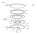
- FIG. 1 is an exploded perspective view schematically showing the configuration of an acoustic sensor according to a first embodiment.
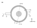
- FIG. 2 is a plan view schematically showing a part of the acoustic sensor according to the first embodiment.
- FIG. 3 is a sectional view taken along line III-III' in FIG. Note that in FIG. 2, the support substrate 11 and the cover member 12 are omitted, and the first connection member 21 and the second connection member 23 are shown with diagonal lines.
- the acoustic sensor 10 includes a piezoelectric plate 30, a support substrate 11, a cover member 12, signal lines 13 and 14, a first connection member 21, and a first insulating member 22. , a second connecting member 23 and a second insulating member 24.
- the first connecting member 21, the first insulating member 22, the piezoelectric plate 30, the second connecting member 23, the second insulating member 24, and the cover member 12 are stacked in this order.
- the piezoelectric plate 30 is a sensor element that converts vibrations of a detected object (for example, a human being) into a corresponding electrical signal.
- the piezoelectric plate 30 includes a piezoelectric element 31 and a conductive plate 32.
- the conductor plate 32 is a plate-shaped member made of a conductor such as a metal material, and has a first surface 32a and a second surface 32b opposite to the first surface 32a.
- the piezoelectric element 31 is provided on the second surface 32b of the conductive plate 32.
- piezoelectric ceramics such as PZT are used, for example.
- the cover member 12 is arranged facing the first surface 32a of the conductor plate 32.
- the cover member 12 is a plate-shaped member made of a conductive material such as a metal material, for example.
- the cover member 12 is a member that transmits vibrations of a detected object (not shown) to the piezoelectric plate 30, and is made of a material that does not substantially undergo compressive deformation. Note that the cover member 12 may be in direct contact with the detected object, or may be in contact with the detected object through another member such as a protective layer.
- the first connecting member 21 and the first insulating member 22 are provided between the piezoelectric plate 30 and the support substrate 11 in the third direction Dz.
- the first connection member 21 is a columnar member, and is provided between the piezoelectric element 31 and the support substrate 11.
- the first connecting member 21 contacts the piezoelectric element 31 at one end in the third direction Dz, and contacts the support substrate 11 at the other end in the third direction Dz.
- the first connection member 21 is made of a conductor and electrically connects the piezoelectric element 31 and the support substrate 11.
- the first insulating member 22 is formed of an insulator and is provided between the second surface 32b of the conductive plate 32 and the support substrate 11 at the outer edge of the second surface 32b of the conductive plate 32. Further, the first insulating member 22 is arranged to overlap with a part of the outer edge of the piezoelectric element 31.
- the first insulating member 22 is an annular member having an opening OP in the center, and the first connecting member 21 is provided at a position overlapping the opening OP of the first insulating member 22. Note that the first insulating member 22 may be arranged without overlapping the outer edge of the piezoelectric element 31.
- the second connecting member 23 and the second insulating member 24 are provided between the piezoelectric plate 30 and the cover member 12 in the third direction Dz.
- the second connection member 23 is made of a conductor and electrically connects the conductor plate 32 and the cover member 12.
- the second connection member 23 is an annular member and is provided at the outer edge of the first surface 32a of the conductor plate 32.
- One end side of the second connecting member 23 in the third direction Dz is in contact with the cover member 12
- the other end side of the second connecting member 23 in the third direction Dz is in contact with the first surface 32 a of the conductor plate 32 .
- the second insulating member 24 is formed of an insulator and is provided between the first surface 32a of the conductive plate 32 and the cover member 12 at the center of the first surface 32a of the conductive plate 32.
- the second insulating member 24 is provided closer to the center than the second connecting member 23 and is disposed within a region surrounded by the second connecting member 23 .
- each member of the acoustic sensor 10 has a circular shape in plan view. It is provided concentrically with respect to the center 32c of the conductive plate 32.
- the diameter of the first connecting member 21 is smaller than the diameter of the piezoelectric element 31.
- the outer diameter of the first insulating member 22 is approximately the same as the diameter of the conductive plate 32.
- the first insulating member 22 is provided along the entire outer edge of the second surface 32 b of the conductor plate 32 and is arranged to surround the first connecting member 21 .
- the diameter of the opening OP of the first insulating member 22 (inner diameter of the first insulating member 22) is larger than the diameter of the first connecting member 21. That is, the first insulating member 22 is provided apart from the first connecting member 21 in the radial direction. Furthermore, the inner edge of the first insulating member 22 that forms the opening OP is provided to cover the entire outer edge of the piezoelectric element 31 .
- the second connection member 23 is provided along the entire outer edge of the first surface 32a of the conductor plate 32.
- the outer diameter of the second connecting member 23 is approximately the same as the diameter of the conductive plate 32.
- the inner diameter of the second connecting member 23 is larger than the diameter of the first connecting member 21 and the diameter of the piezoelectric element 31.
- the diameter of the second insulating member 24 is approximately equal to the inner diameter of the second connecting member 23.
- the second insulating member 24 is provided in a region that overlaps with the opening OP of the piezoelectric element 31, the first connecting member 21, and the first insulating member 22 in plan view.
- the outer periphery of the second insulating member 24 is provided in contact with the inner periphery of the second connecting member 23 .
- the diameter of the second insulating member 24 may be smaller than the inner diameter of the second connecting member 23, and the outer periphery of the second insulating member 24 has a space with the inner periphery of the second connecting member 23. You can do it and stay away.
- the diameter of the support substrate 11 and the diameter of the cover member 12 are equivalent to the diameter of the conductor plate 32 of the piezoelectric plate 30.
- the present invention is not limited thereto, and the diameter of the support substrate 11 and the diameter of the cover member 12 may be larger than the diameter of the conductor plate 32 of the piezoelectric plate 30. Further, the diameter of the support substrate 11 and the diameter of the cover member 12 are the same, but may be different diameters.
- the first connecting member 21 is harder than the first insulating member 22 .
- the material used for the first connection member 21 is carbon-based silicone, urethane foam, polybutadiene, or the like.
- the material of the first connecting member 21 is a closed foam structure.
- the hardness of the first connecting member 21 is approximately Shore hardness A70.
- the volume resistivity of the first connecting member 21 is about 1 ⁇ 10 ⁇ 2 ( ⁇ m) or more and 1 ⁇ 10 2 ( ⁇ m) or less.
- the first insulating member 22 may be made of a PET film, natural rubber (NR), chloroprene rubber (CR), polyethylene (PE), ethylene propylene rubber (EPDM), acrylic, or the like. Moreover, it is preferable that the material of the first insulating member 22 is a closed foam structure.
- the hardness of the first insulating member 22 is approximately Shore hardness A20.
- the volume resistivity of the first insulating member 22 is about 1 ⁇ 10 ⁇ 26 ( ⁇ m) or more and 1 ⁇ 10 10 ( ⁇ m) or less.
- the second connecting member 23 is made of the same material as the first connecting member 21 described above, and the second insulating member 24 is made of the same material as the first insulating member 22 described above. That is, the hardness of the second connecting member 23 is harder than the hardness of the second insulating member 24.
- the material example, hardness, and volume resistivity of the second connection member 23 are the same as those of the first connection member 21 described above, and repeated explanation will be omitted. Further, the material example, hardness, and volume resistivity of the second insulating member 24 are the same as those of the first insulating member 22 described above, and repeated explanation will be omitted.
- the second connecting member 23 may be made of the same material as the first connecting member 21, or may be made of a different material.
- the second insulating member 24 may be made of the same material as the first insulating member 22, or may be made of a different material.
- the second insulating member 24 may be formed of an air layer.
- the second connection member 23 which is harder than the second insulating member 24, is formed in an annular shape along the outer edge of the conductor plate 32.
- the first insulating member 22 is provided in an area overlapping with the second connecting member 23, and the first connecting member 21, which is harder than the first insulating member 22, is provided in the center of the piezoelectric element 31. provided. Therefore, the center part of the piezoelectric element 31 is supported by the first insulating member 22 and its displacement is suppressed, and the outer edge side of the conductive plate 32 and the outer edge side of the piezoelectric element 31 are elastically deformed by the first insulating member 22. The piezoelectric element 31 is more easily displaced than the center part. Therefore, when the displacement of the cover member 12 is transmitted through the second connection member 23, the outer edge side of the conductor plate 32 and the outer edge side of the piezoelectric element 31 are displaced, and the piezoelectric element 31 is deflected and deformed.
- the piezoelectric element 31 outputs an electrical signal according to the deformation.
- the electrical signal from the piezoelectric element 31 is output to an external terminal (for example, the detection circuits 50 and 50A (see FIGS. 6 and 12)) via the first connection member 21, the support substrate 11, and the signal line 13. Further, the electrical signal from the conductor plate 32 is output to the external terminal via the second connection member 23, the cover member 12, and the signal line 14.
- the first connecting member 21 supports the center portion of the piezoelectric plate 30, and the second connecting member 23 transmits the vibration of the detected object to the outer edge side of the piezoelectric plate 30.
- the first connecting member 21 and the second connecting member 23 also serve as electrical connecting members that output electrical signals from the piezoelectric plate 30 to the outside. Therefore, there is no need to connect a cable to the piezoelectric element 31 and the conductive plate 32 for extracting the electric signal to the outside. As a result, it is not necessary to form a through hole in the support substrate 11 and the cover member 12 for passing the cable through. Therefore, the acoustic sensor 10 can have a simpler configuration than when a cable is connected to the piezoelectric plate 30. As a result, the overall configuration of the acoustic sensor 10 including the wiring connected to the piezoelectric plate 30 and external circuits (for example, the detection circuit 50 (see FIG. 6, etc.)) can be made smaller.
- the first surface 32a side of the conductor plate 32 has the second connection member 23, the second insulating member 24, and the cover member. 12 allows for easy sealing. Further, the second surface 32b side of the conductor plate 32 can be easily sealed by the first connecting member 21, the first insulating member 22, and the support substrate 11. Therefore, the acoustic sensor 10 can have a liquid-tight structure in which both sides of the piezoelectric plate 30 are sealed, if necessary.
- the second connecting member 23 which is harder than the second insulating member 24, is formed in an annular shape.
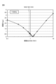
- FIG. 4 is a graph showing the relationship between frequency and sensitivity of the acoustic sensor according to the example for each hardness ratio between the connecting member and the insulating member.
- FIG. 5 is a graph showing the relationship between the hardness ratio of the connecting member and the insulating member and the sensitivity of the acoustic sensor according to the example.
- the frequency in FIGS. 4 and 5 is the drive frequency of the displacement given to the cover member 12.
- the hardness ratio in FIGS. 4 and 5 is the ratio of the hardness of the first insulating member 22 (hereinafter referred to as Shore hardness SH2) to the hardness of the first connecting member 21 (hereinafter referred to as Shore hardness SH1) ( SH2/SH1). Note that the hardness and hardness ratio of the second connecting member 23 and the second insulating member 24 are the same as those of the first connecting member 21 and the first insulating member 22, respectively.
- the diameter of the piezoelectric plate 30 (the diameter of the conductor plate 32) was set to 15 mm.
- the first connecting member 21 is made of a conductive material having a diameter of 9 mm, a thickness of 1 mm, and a shore hardness of A70, for example.
- the first insulating member 22 had an outer diameter of 20 mm, an inner diameter of 10 mm, a thickness of 1 mm, and was made of an insulating material with a Shore hardness of A20.
- the second connecting member 23 is made of, for example, an electrically conductive material with an outer diameter of 20 mm, an inner diameter of 10 mm, a thickness of 1 mm, and a Shore hardness of A70.
- the second insulating member 24 had a diameter of 9 mm, a thickness of 1 mm, and was made of an insulating material with a Shore hardness of A20.
- the support substrate 11 and the cover member 12 were each metal plates with a diameter of 20 mm and a thickness of 0.5 mm.
- FIG. 4 shows the sensitivity (output voltage) of the piezoelectric plate 30 when the hardness ratio SH2/SH1 is different from 0.5, 1.0, and 2.0 in the acoustic sensor 10 according to the example.
- the piezoelectric plate 30 exhibits constant sensitivity (output voltage) to changes in frequency.
- the piezoelectric plate 30 exhibits different sensitivities (output voltages) for each hardness ratio SH2/SH1.
- FIG. 4 shows the sensitivity (output voltage) of the piezoelectric plate 30 when the frequency is constant at 505 Hz.
- the sensitivity (output voltage) changes depending on the change in the hardness ratio SH2/SH1.
- SH2/SH1 is SH2/SH1>1, that is, when the hardness of the first insulating member 22 is harder than the hardness of the first connecting member 21, the sensitivity (output voltage) increases as the hardness ratio SH2/SH1 increases. growing.
- SH2/SH1>1 the piezoelectric element 31 may be deformed in the tensile direction, which may reduce durability.
- the hardness ratio SH2/SH1 0.9.
- FIG. 6 is an exploded perspective view schematically showing the configuration of an acoustic sensor according to the second embodiment.
- FIG. 7 is a sectional view schematically showing the configuration of an acoustic sensor according to the second embodiment.
- the support substrate 11A is an insulating substrate formed of an insulator.
- a printed wiring board is used as the support substrate 11A, for example.
- the support substrate 11A has a base made of an insulating resin material and has a conductive member 15a inside.
- the support substrate 11A has contacts that penetrate through the front surface 11Aa (the surface facing the piezoelectric element 31) and the back surface 11Ab (the surface opposite to the surface facing the piezoelectric element 31).
- a hole 15 is provided.
- the conductive member 15a is filled in the contact hole 15 and electrically connects the front surface 11Aa side and the back surface 11Ab side.
- One end side of the contact hole 15 is electrically connected to the first connecting member 21 on the surface 11Aa of the support substrate 11A.
- the other end side of the contact hole 15 (conductive member 15a) is electrically connected to the connection wiring 16 on the back surface 11Ab of the support substrate 11A.
- the piezoelectric element 31 of the piezoelectric plate 30 is electrically connected to the back surface 11Ab side of the support substrate 11A via the first connection member 21 and the contact hole 15 (conductive member 15a).
- the acoustic sensor 10A of the second embodiment has a detection circuit 50 (not shown in FIG. 7) provided on the back surface 11Ab of the support substrate 11A.
- the detection circuit 50 is configured of, for example, an IC (Integrated Circuit), and is a circuit that processes electrical signals from the piezoelectric plate 30.
- the support substrate 11A by using an insulating substrate as the support substrate 11A, the support substrate 11A has a substrate supporting the piezoelectric plate 30, and various wirings such as the connection wiring 16 and components such as the detection circuit 50 mounted thereon. It also serves as a wiring board. Therefore, the acoustic sensor 10A can achieve miniaturization of the entire configuration including the detection circuit 50.
- the support substrate 11A is not limited to the configuration having the connection wiring 16, the contact hole 15, and the conductive member 15a, but may have wiring provided in an inner layer, a plurality of contact holes, and a conductive member. Further, the back surface 11Ab of the support substrate 11A is not limited to the detection circuit 50, and other mounted components or circuits may be provided.
- FIG. 8 is an exploded perspective view schematically showing the configuration of an acoustic sensor according to the third embodiment.
- FIG. 9 is a plan view schematically showing the configuration of a support substrate according to the third embodiment.
- FIG. 10 is a plan view schematically showing the configuration of the back side of the support substrate according to the third embodiment.
- FIG. 11 is a sectional view taken along line XI-XI' in FIG.
- the acoustic sensor 10B includes a third connection member 25 that electrically connects the support substrate 11B and the cover member 12 will be described. do.
- the support substrate 11B and the cover member 12 have a larger diameter (outer shape) than the conductor plate 32 of the piezoelectric plate 30.
- the support substrate 11B is an insulating substrate made of an insulator similarly to the second embodiment.
- the piezoelectric element 31 of the piezoelectric plate 30 is electrically connected to the back surface 11Bb side of the support substrate 11B via the first connection member 21 and the contact hole 15 (conductive member 15a). Ru.
- cover member 12 is a film-like member made of a conductive material.
- the conductor plate 32 of the piezoelectric plate 30 is electrically connected to the cover member 12 via the second connection member 23.
- the third connection member 25 is formed of a conductor, is provided outside the outer periphery of the conductor plate 32 of the piezoelectric plate 30, and electrically connects the support substrate 11B and the cover member 12. More specifically, as shown in FIG. 11, the third connecting member 25 has an annular shape surrounding the piezoelectric plate 30, the first connecting member 21, the first insulating member 22, the second connecting member 23, and the second insulating member 24. be.
- the third connection member 25 is provided in an annular shape along the entire outer edge of the support substrate 11B. Further, the third connecting member 25 is arranged apart from the outer periphery of the conductive plate 32 of the piezoelectric plate 30, the first insulating member 22, and the second connecting member 23 with a space therebetween.
- One end side of the third connection member 25 in the third direction Dz is in contact with the cover member 12, and the other end side of the third connection member 25 in the third direction Dz is electrically connected to the surface 11Ba side of the support substrate 11B via the connection wiring 18. connected.
- connection wiring 18 is provided in a ring shape along the area overlapping with the third connection member 25, that is, along the entire outer edge of the surface 11Ba of the support substrate 11B.
- a contact hole 17 passing through the front surface 11Ba and the back surface 11Bb is provided at a position overlapping the connection wiring 18 of the support substrate 11B.
- the conductive member 17a is filled in the contact hole 17 and electrically connects the front surface 11Ba side and the back surface 11Bb side.
- the first connection member 21 is electrically connected to the back surface 11Bb side of the support substrate 11B via the contact hole 15 (conductive member 15a) at the center of the support substrate 11B. be done.
- a detection circuit 50A is provided on the back surface 11Bb of the support substrate 11B.
- the third connection member 25 is electrically connected to the detection circuit 50A via the contact hole 17 (conductive member 17a) and wiring provided on the back surface 11Bb.
- the first connecting member 21 is electrically connected to the detection circuit 50A via the contact hole 15 (conductive member 15a) and wiring provided on the back surface 11Bb. Note that a detailed configuration example of the detection circuit 50A will be described later with reference to FIG.
- the piezoelectric element 31 of the piezoelectric plate 30 is electrically connected to the detection circuit 50A on the back surface 11Bb of the support substrate 11B via the first connection member 21 and the contact hole 15 (conductive member 15a).
- the conductive plate 32 of the piezoelectric plate 30 connects to the detection circuit on the back surface 11Bb of the support substrate 11B via the second connection member 23, the cover member 12, the third connection member 25, the connection wiring 18, and the contact hole 17 (conductive member 17a). It is electrically connected to 50A.
- the cover member 12 is formed of a deformable film-like member, so the vibration of the detected object is transmitted to the cover member 12 and the second connecting member 23. It is transmitted well to the piezoelectric plate 30 via.
- the support substrate 11B has a connecting portion 19 that protrudes radially outward from the outer periphery.
- the detection circuit 50A is electrically connected to an external control board via a plurality of connection wires 16 provided in the connection portion 19.
- the plurality of connection wiring lines 16 include, for example, a ground line 16a that supplies a ground potential to the piezoelectric plate 30, a signal line 16b that outputs a signal from the piezoelectric plate 30 via the detection circuit 50A, and a power supply potential to the detection circuit 50A. It includes the power supply line 16c and the like.
- FIG. 12 is a circuit diagram showing a configuration example of a detection circuit of an acoustic sensor according to the third embodiment.
- the detection circuit 50A includes a protection circuit 51, an active filter 52, a constant voltage circuit 53, and a signal processing circuit 54.
- the protection circuit 51 is a circuit for protecting the piezoelectric plate 30 from overvoltage and the like, and includes diodes 51a and 51b electrically connected to the piezoelectric plate 30.
- the active filter 52 is a filter circuit that passes signals in a predetermined frequency range among the signals from the piezoelectric plate 30, and includes an amplifier 52a, resistive elements 52b and 52c, and a capacitor 52d.
- active filter 52 is configured as a low-pass filter.
- the active filter 52 may be a high-pass filter or a band-pass filter.
- the present invention is not limited to the active filter 52, and a passive filter may be provided, or the amplifier 52a may be simply connected.
- the number of active filters 52 is not limited to one stage, and may be connected in multiple stages.
- the constant voltage circuit 53 is a circuit that supplies a constant voltage to the amplifier 52a of the active filter 52, and includes resistance elements 53a and 53b.
- the signal processing circuit 54 is a circuit that processes signals from the piezoelectric plate 30, and includes an A/D conversion circuit 54a and a signal processing section 54b.
- the A/D conversion circuit 54a is a circuit that converts an analog signal from the piezoelectric plate 30 into a digital signal.
- the signal processing section 54b is a circuit that receives the digital signal from the A/D conversion circuit 54a and performs signal processing such as amplification and filtering.
- the protection circuit 51, active filter 52, and constant voltage circuit 53 of the detection circuit 50A are provided on the back surface 11Bb of the support substrate 11B, and the signal processing circuit 54 is provided on an external control board.
- the signal line 16b (see FIG. 10) provided in the connection portion 19 is provided as a wiring for extracting an analog signal from the active filter 52.
- the present invention is not limited to this, and all of the detection circuit 50A including the signal processing circuit 54 may be provided on the back surface 11Bb of the support substrate 11B.
- the signal line 16b (see FIG. 10) provided in the connection section 19 is configured not as an analog signal output but as a plurality of digital I/F signal input/output terminals.
- a serial port such as SPI, I2C, USB, or UART, or a parallel port is provided as a digital I/F signal input/output terminal.
- the cover member 12 is electrically connected to the support substrate 11B via the third connection member 25. Therefore, the detection circuit 50A and various wirings can be provided together on the support substrate 11B, and the entire acoustic sensor 10B including the detection circuit 50A and various wirings can be miniaturized.
- FIG. 13 is an explanatory diagram for explaining a stethoscope according to the fourth embodiment.
- a stethoscope 100 according to the fourth embodiment includes a chest piece 101, a Y-shaped tube 103, two ear tubes 104, and two ear tips 105.
- the chest piece 101 has a housing 101a and a contact portion 101b.
- the acoustic sensors 10, 10A, and 10B are incorporated inside the housing 101a.
- the contact portion 101b is a member that comes into contact with a living body (for example, a human being), and is configured to transmit vibrations of the living body to the cover member 12 (see FIG. 1, etc.).
- the chest piece 101 of the stethoscope 100 includes a signal processing circuit, an amplifier, a speaker, etc. that converts electrical signals from the piezoelectric plates 30 of the acoustic sensors 10, 10A, 10B into audio.
- the stethoscope 100 may include a wireless communication module that transmits electrical signals from the piezoelectric plates 30 of the acoustic sensors 10, 10A, and 10B to the outside as necessary.
- the Y-shaped tube 103 connects the chest piece 101 and the two Eustachian tubes 104.
- Two ear tips 105 are connected to each of the two ear canals 104. Sound generated based on electrical signals from the piezoelectric plates 30 of the acoustic sensors 10, 10A, 10B is output to the outside via the two ear tips 105.
- the chest piece 101 can be made smaller. Furthermore, since the acoustic sensors 10, 10A, and 10B can have a liquid-tight structure in which both sides of the piezoelectric plate 30 are sealed, the stethoscope 100 having the acoustic sensors 10, 10A, and 10B is free from moisture and disinfectant infiltration. Damage to the piezoelectric plate 30 and the detection circuits 50 and 50A can be suppressed.
- the stethoscope 100 having the acoustic sensors 10, 10A, and 10B has been described, but the acoustic sensors 10, 10A, and 10B can be applied to other devices than the stethoscope 100.
- the acoustic sensors 10, 10A, and 10B may be applied to a heart sound sensor that is kept attached to a living body for a long time in order to monitor heart sounds.
- the piezoelectric plate 30, the support substrate 11, and the cover member 12 have a circular shape in a plan view, but the piezoelectric plate 30, the support substrate 11, and the cover member 12 have a rectangular shape, a polygonal shape, etc. etc., other shapes may also be used.
Landscapes
- Engineering & Computer Science (AREA)
- Acoustics & Sound (AREA)
- Physics & Mathematics (AREA)
- Life Sciences & Earth Sciences (AREA)
- Signal Processing (AREA)
- Mechanical Engineering (AREA)
- Health & Medical Sciences (AREA)
- Biomedical Technology (AREA)
- Multimedia (AREA)
- Heart & Thoracic Surgery (AREA)
- Medical Informatics (AREA)
- Molecular Biology (AREA)
- Surgery (AREA)
- Animal Behavior & Ethology (AREA)
- General Health & Medical Sciences (AREA)
- Public Health (AREA)
- Veterinary Medicine (AREA)
- Measurement Of Mechanical Vibrations Or Ultrasonic Waves (AREA)
- Piezo-Electric Transducers For Audible Bands (AREA)
Priority Applications (2)
| Application Number | Priority Date | Filing Date | Title |
|---|---|---|---|
| JP2024530754A JP7776006B2 (ja) | 2022-07-01 | 2023-06-22 | 音響センサ及び聴診器 |
| US19/001,139 US20250127478A1 (en) | 2022-07-01 | 2024-12-24 | Acoustic sensor and stethoscope |
Applications Claiming Priority (2)
| Application Number | Priority Date | Filing Date | Title |
|---|---|---|---|
| JP2022106921 | 2022-07-01 | ||
| JP2022-106921 | 2022-07-01 |
Related Child Applications (1)
| Application Number | Title | Priority Date | Filing Date |
|---|---|---|---|
| US19/001,139 Continuation US20250127478A1 (en) | 2022-07-01 | 2024-12-24 | Acoustic sensor and stethoscope |
Publications (1)
| Publication Number | Publication Date |
|---|---|
| WO2024004823A1 true WO2024004823A1 (ja) | 2024-01-04 |
Family
ID=89382944
Family Applications (1)
| Application Number | Title | Priority Date | Filing Date |
|---|---|---|---|
| PCT/JP2023/023161 Ceased WO2024004823A1 (ja) | 2022-07-01 | 2023-06-22 | 音響センサ及び聴診器 |
Country Status (3)
| Country | Link |
|---|---|
| US (1) | US20250127478A1 (https=) |
| JP (1) | JP7776006B2 (https=) |
| WO (1) | WO2024004823A1 (https=) |
Citations (3)
| Publication number | Priority date | Publication date | Assignee | Title |
|---|---|---|---|---|
| WO2011163509A1 (en) * | 2010-06-24 | 2011-12-29 | Cvr Global, Inc. | Sensor, sensor pad and sensor array for detecting infrasonic acoustic signals |
| CN206593752U (zh) * | 2017-03-02 | 2017-10-27 | 纳智源科技(唐山)有限责任公司 | 接触式声音探测传感器以及接触式声音传感装置 |
| WO2021106865A1 (ja) * | 2019-11-29 | 2021-06-03 | 株式会社村田製作所 | 生体音響センサおよびそれを備えた聴診器 |
-
2023
- 2023-06-22 JP JP2024530754A patent/JP7776006B2/ja active Active
- 2023-06-22 WO PCT/JP2023/023161 patent/WO2024004823A1/ja not_active Ceased
-
2024
- 2024-12-24 US US19/001,139 patent/US20250127478A1/en active Pending
Patent Citations (3)
| Publication number | Priority date | Publication date | Assignee | Title |
|---|---|---|---|---|
| WO2011163509A1 (en) * | 2010-06-24 | 2011-12-29 | Cvr Global, Inc. | Sensor, sensor pad and sensor array for detecting infrasonic acoustic signals |
| CN206593752U (zh) * | 2017-03-02 | 2017-10-27 | 纳智源科技(唐山)有限责任公司 | 接触式声音探测传感器以及接触式声音传感装置 |
| WO2021106865A1 (ja) * | 2019-11-29 | 2021-06-03 | 株式会社村田製作所 | 生体音響センサおよびそれを備えた聴診器 |
Also Published As
| Publication number | Publication date |
|---|---|
| US20250127478A1 (en) | 2025-04-24 |
| JPWO2024004823A1 (https=) | 2024-01-04 |
| JP7776006B2 (ja) | 2025-11-26 |
Similar Documents
| Publication | Publication Date | Title |
|---|---|---|
| CN112565994B (zh) | 用于产生和/或检测声波的音频转换单元及其制造方法、发声单元 | |
| CN105191350B (zh) | 静电容量式传感器、声音传感器以及麦克风 | |
| CN108141678B (zh) | 具有固定的内部区域的微机电麦克风 | |
| US9521499B2 (en) | Electronic device with large back volume for electromechanical transducer | |
| JP5324668B2 (ja) | 音響エネルギー変換器 | |
| CN210609600U (zh) | 麦克风模组及电子产品 | |
| KR101612851B1 (ko) | 초소형 보청기 | |
| JPWO2010073598A1 (ja) | 平衡信号出力型センサー | |
| JP6478317B2 (ja) | 外耳道装着型イヤホンマイク | |
| WO2005029012A1 (ja) | 振動センサ | |
| WO2019208127A1 (ja) | 半導体装置及び電子機器 | |
| KR101514567B1 (ko) | 음향 소자 및 이를 구비하는 마이크로폰 패키지 | |
| JP7776006B2 (ja) | 音響センサ及び聴診器 | |
| CN212519427U (zh) | 麦克风阵列器件与终端设备 | |
| US11560303B2 (en) | MEMS device with a diaphragm having a net compressive stress | |
| US20110243350A1 (en) | Low noise electret microphone | |
| CN216491057U (zh) | 一种麦克风结构及电子设备 | |
| CN101427594B (zh) | 驻极体电容传声器 | |
| JPWO2018051703A1 (ja) | 力センサ、および、力センサの製造方法 | |
| JP5249901B2 (ja) | コンデンサマイクロホン | |
| CN112788481A (zh) | 麦克风模组 | |
| JP6721467B2 (ja) | マイクロホン | |
| KR20120054244A (ko) | 마이크로폰 | |
| JP7182185B2 (ja) | 生体情報測定装置 | |
| HK40051185A (en) | Audio conversion unit for generating and/or detecting acoustic wave |
Legal Events
| Date | Code | Title | Description |
|---|---|---|---|
| 121 | Ep: the epo has been informed by wipo that ep was designated in this application |
Ref document number: 23831267 Country of ref document: EP Kind code of ref document: A1 |
|
| ENP | Entry into the national phase |
Ref document number: 2024530754 Country of ref document: JP Kind code of ref document: A |
|
| WWE | Wipo information: entry into national phase |
Ref document number: 202417103879 Country of ref document: IN |
|
| NENP | Non-entry into the national phase |
Ref country code: DE |
|
| 122 | Ep: pct application non-entry in european phase |
Ref document number: 23831267 Country of ref document: EP Kind code of ref document: A1 |