WO2024004481A1 - 血液浄化装置及び送液ポンプの制御方法 - Google Patents
血液浄化装置及び送液ポンプの制御方法 Download PDFInfo
- Publication number
- WO2024004481A1 WO2024004481A1 PCT/JP2023/019908 JP2023019908W WO2024004481A1 WO 2024004481 A1 WO2024004481 A1 WO 2024004481A1 JP 2023019908 W JP2023019908 W JP 2023019908W WO 2024004481 A1 WO2024004481 A1 WO 2024004481A1
- Authority
- WO
- WIPO (PCT)
- Prior art keywords
- flow rate
- dialysate
- pump
- control
- liquid
- Prior art date
- Legal status (The legal status is an assumption and is not a legal conclusion. Google has not performed a legal analysis and makes no representation as to the accuracy of the status listed.)
- Ceased
Links
Images



Classifications
-
- A—HUMAN NECESSITIES
- A61—MEDICAL OR VETERINARY SCIENCE; HYGIENE
- A61M—DEVICES FOR INTRODUCING MEDIA INTO, OR ONTO, THE BODY; DEVICES FOR TRANSDUCING BODY MEDIA OR FOR TAKING MEDIA FROM THE BODY; DEVICES FOR PRODUCING OR ENDING SLEEP OR STUPOR
- A61M1/00—Suction or pumping devices for medical purposes; Devices for carrying-off, for treatment of, or for carrying-over, body-liquids; Drainage systems
- A61M1/14—Dialysis systems; Artificial kidneys; Blood oxygenators ; Reciprocating systems for treatment of body fluids, e.g. single needle systems for hemofiltration or pheresis
- A61M1/16—Dialysis systems; Artificial kidneys; Blood oxygenators ; Reciprocating systems for treatment of body fluids, e.g. single needle systems for hemofiltration or pheresis with membranes
- A61M1/1621—Constructional aspects thereof
- A61M1/1647—Constructional aspects thereof with flow rate measurement of the dialysis fluid, upstream and downstream of the dialyser
-
- A—HUMAN NECESSITIES
- A61—MEDICAL OR VETERINARY SCIENCE; HYGIENE
- A61M—DEVICES FOR INTRODUCING MEDIA INTO, OR ONTO, THE BODY; DEVICES FOR TRANSDUCING BODY MEDIA OR FOR TAKING MEDIA FROM THE BODY; DEVICES FOR PRODUCING OR ENDING SLEEP OR STUPOR
- A61M1/00—Suction or pumping devices for medical purposes; Devices for carrying-off, for treatment of, or for carrying-over, body-liquids; Drainage systems
- A61M1/14—Dialysis systems; Artificial kidneys; Blood oxygenators ; Reciprocating systems for treatment of body fluids, e.g. single needle systems for hemofiltration or pheresis
- A61M1/16—Dialysis systems; Artificial kidneys; Blood oxygenators ; Reciprocating systems for treatment of body fluids, e.g. single needle systems for hemofiltration or pheresis with membranes
- A61M1/1621—Constructional aspects thereof
- A61M1/165—Constructional aspects thereof with a dialyser bypass on the dialysis fluid line
-
- F—MECHANICAL ENGINEERING; LIGHTING; HEATING; WEAPONS; BLASTING
- F04—POSITIVE - DISPLACEMENT MACHINES FOR LIQUIDS; PUMPS FOR LIQUIDS OR ELASTIC FLUIDS
- F04B—POSITIVE-DISPLACEMENT MACHINES FOR LIQUIDS; PUMPS
- F04B23/00—Pumping installations or systems
- F04B23/04—Combinations of two or more pumps
-
- F—MECHANICAL ENGINEERING; LIGHTING; HEATING; WEAPONS; BLASTING
- F04—POSITIVE - DISPLACEMENT MACHINES FOR LIQUIDS; PUMPS FOR LIQUIDS OR ELASTIC FLUIDS
- F04B—POSITIVE-DISPLACEMENT MACHINES FOR LIQUIDS; PUMPS
- F04B51/00—Testing machines, pumps, or pumping installations
-
- A—HUMAN NECESSITIES
- A61—MEDICAL OR VETERINARY SCIENCE; HYGIENE
- A61M—DEVICES FOR INTRODUCING MEDIA INTO, OR ONTO, THE BODY; DEVICES FOR TRANSDUCING BODY MEDIA OR FOR TAKING MEDIA FROM THE BODY; DEVICES FOR PRODUCING OR ENDING SLEEP OR STUPOR
- A61M2205/00—General characteristics of the apparatus
- A61M2205/16—General characteristics of the apparatus with back-up system in case of failure
-
- A—HUMAN NECESSITIES
- A61—MEDICAL OR VETERINARY SCIENCE; HYGIENE
- A61M—DEVICES FOR INTRODUCING MEDIA INTO, OR ONTO, THE BODY; DEVICES FOR TRANSDUCING BODY MEDIA OR FOR TAKING MEDIA FROM THE BODY; DEVICES FOR PRODUCING OR ENDING SLEEP OR STUPOR
- A61M2205/00—General characteristics of the apparatus
- A61M2205/17—General characteristics of the apparatus with redundant control systems
-
- A—HUMAN NECESSITIES
- A61—MEDICAL OR VETERINARY SCIENCE; HYGIENE
- A61M—DEVICES FOR INTRODUCING MEDIA INTO, OR ONTO, THE BODY; DEVICES FOR TRANSDUCING BODY MEDIA OR FOR TAKING MEDIA FROM THE BODY; DEVICES FOR PRODUCING OR ENDING SLEEP OR STUPOR
- A61M2205/00—General characteristics of the apparatus
- A61M2205/18—General characteristics of the apparatus with alarm
-
- A—HUMAN NECESSITIES
- A61—MEDICAL OR VETERINARY SCIENCE; HYGIENE
- A61M—DEVICES FOR INTRODUCING MEDIA INTO, OR ONTO, THE BODY; DEVICES FOR TRANSDUCING BODY MEDIA OR FOR TAKING MEDIA FROM THE BODY; DEVICES FOR PRODUCING OR ENDING SLEEP OR STUPOR
- A61M2205/00—General characteristics of the apparatus
- A61M2205/33—Controlling, regulating or measuring
- A61M2205/3331—Pressure; Flow
- A61M2205/3334—Measuring or controlling the flow rate
-
- A—HUMAN NECESSITIES
- A61—MEDICAL OR VETERINARY SCIENCE; HYGIENE
- A61M—DEVICES FOR INTRODUCING MEDIA INTO, OR ONTO, THE BODY; DEVICES FOR TRANSDUCING BODY MEDIA OR FOR TAKING MEDIA FROM THE BODY; DEVICES FOR PRODUCING OR ENDING SLEEP OR STUPOR
- A61M2205/00—General characteristics of the apparatus
- A61M2205/33—Controlling, regulating or measuring
- A61M2205/3331—Pressure; Flow
- A61M2205/3341—Pressure; Flow stabilising pressure or flow to avoid excessive variation
-
- A—HUMAN NECESSITIES
- A61—MEDICAL OR VETERINARY SCIENCE; HYGIENE
- A61M—DEVICES FOR INTRODUCING MEDIA INTO, OR ONTO, THE BODY; DEVICES FOR TRANSDUCING BODY MEDIA OR FOR TAKING MEDIA FROM THE BODY; DEVICES FOR PRODUCING OR ENDING SLEEP OR STUPOR
- A61M2205/00—General characteristics of the apparatus
- A61M2205/33—Controlling, regulating or measuring
- A61M2205/3365—Rotational speed
-
- A—HUMAN NECESSITIES
- A61—MEDICAL OR VETERINARY SCIENCE; HYGIENE
- A61M—DEVICES FOR INTRODUCING MEDIA INTO, OR ONTO, THE BODY; DEVICES FOR TRANSDUCING BODY MEDIA OR FOR TAKING MEDIA FROM THE BODY; DEVICES FOR PRODUCING OR ENDING SLEEP OR STUPOR
- A61M2205/00—General characteristics of the apparatus
- A61M2205/70—General characteristics of the apparatus with testing or calibration facilities
-
- F—MECHANICAL ENGINEERING; LIGHTING; HEATING; WEAPONS; BLASTING
- F04—POSITIVE - DISPLACEMENT MACHINES FOR LIQUIDS; PUMPS FOR LIQUIDS OR ELASTIC FLUIDS
- F04B—POSITIVE-DISPLACEMENT MACHINES FOR LIQUIDS; PUMPS
- F04B2205/00—Fluid parameters
- F04B2205/09—Flow through the pump
Definitions
- the present invention relates to a blood purification device and a method of controlling a liquid pump.
- This blood purification device includes a blood purifier, a dialysate line that supplies dialysate to the blood purifier, a drainage line from which waste fluid is discharged from the blood purifier, and a fluid delivery line installed in the dialysate line. It includes a pump (dialysate pump) and a water balance amount detection unit that detects the water balance amount (water removal amount) between dialysate and drainage fluid, and feeds back the detection result detected by the water balance amount detection unit. , controls the drive of the liquid pump.
- the present invention provides a blood purification device and a drive control for the liquid pump that can shorten the time until the flow rate of the liquid pump reaches near the target flow rate and suppress flow rate fluctuations due to feedback control.
- the purpose is to provide a method.
- a blood purification apparatus is a blood purification apparatus that performs blood purification treatment through a blood purifier that purifies the blood of a patient, and supplies dialysate to the blood purifier and performs the blood purification.
- a dialysate circuit that discharges dialysate from the device, a fluid pump that is disposed in the dialysate circuit and that transports dialysate in the dialysate circuit, and the flow rate of the fluid pump is a target flow rate.
- a drive control unit that executes a drive control operation to control the liquid transfer pump; and a flow rate detection unit that detects the flow rate of the liquid transfer pump, and in the drive control operation, the detected value of the flow rate detection unit
- Feedforward control is performed that is not based on the flow rate, and the feedforward control is switched to feedback control based on the detected value of the flow rate detection section on the condition that a predetermined time has elapsed or a predetermined flow rate has been reached.
- a method for controlling a liquid pump includes a method for controlling a liquid pump disposed in a dialysate circuit of a blood purification device, which controls the liquid pump so that the flow rate of the liquid pump disposed in a dialysate circuit of a blood purification device becomes a target flow rate.
- a method for controlling a liquid pump wherein feedforward control is performed not based on a detected value of a flow rate detection unit that detects the flow rate of the liquid pump, and the feedforward control is performed on the condition that a predetermined time elapses or a predetermined flow rate is reached. Then, the control is switched to feedback control based on the detected value of the flow rate detection section.
- 1 is a schematic structural diagram showing the structure of a blood purification device according to an embodiment of the present invention.
- 3 is a flowchart showing the first half of a calibration operation.
- 7 is a flowchart showing the second half of the calibration operation. It is a graph showing an example of a command value and a flow rate with respect to time in a supply pump drive control operation and a drainage pump drive control operation. It is a flowchart which showed the liquid supply pump drive control operation. It is a flow chart showing drainage pump drive control operation. It is a flow chart which showed a modification of supply pump drive control operation.
- This blood purification device is a medical device that performs blood purification treatment to purify a patient's blood via a dialyzer.
- this blood purification device uses feedforward control and feedback control to quickly reach near the target flow rate and to achieve stable flow control.
- the blood purification device 1 includes a dialyzer 10 that purifies the blood of a patient C, an extracorporeal circulation unit 11 that circulates the blood of the patient C via the dialyzer 10, and a dialyzer 10 connected to the dialyzer 10.
- the dialyzer 10 includes a dialysate supply and discharge unit 12 that supplies dialysate to the dialyzer 10 and discharges the dialysate from the dialyzer 10.
- the extracorporeal circulation unit 11 and the dialysate supply/drainage unit 12 are configured separately, and the dialyzer 10 is detachably attached to the extracorporeal circulation unit 11 via a fixing jig 13.
- Dialyzer 10 is an example of a blood purifier.
- the dialyzer 10 includes a blood purification membrane (a hollow fiber type hemodialysis membrane, a hemodiafiltration membrane, a flat membrane type hemodialysis membrane, or a hemofiltration membrane).
- the dialyzer 10 also has a blood inlet 10a for introducing blood and a blood outlet 10b for discharging the introduced blood, as well as a dialysate inlet 10c for introducing dialysate and a dialysate drain for discharging the introduced dialysate. It has an outlet 10d.
- blood is purified by bringing the blood into contact with a dialysate via a blood purification membrane. Further, in the dialyzer 10, water can be removed from blood by controlling the supply and drainage of the dialysate fluid supply and discharge unit 12.
- the extracorporeal circulation unit 11 includes an extracorporeal circulation circuit 21 that circulates the blood of the patient C via the dialyzer 10, and a control section 22.
- the control unit 22 will be described later.
- the extracorporeal circulation circuit 21 is connected to the blood inlet 10a of the dialyzer 10, and is connected to the arterial blood flow path 31 that guides blood collected from the blood vessel of the patient C to the dialyzer 10, and the blood outlet 10b of the dialyzer 10, and is connected to the blood outlet 10b of the dialyzer 10.
- the blood pump 10 has a venous blood flow path 32 that returns blood discharged from the patient C to the blood vessel of the patient C, and a blood pump 34 that is disposed in the arterial blood flow path 31 and circulates blood. By driving the blood pump 34, blood from the patient C is guided to the dialyzer 10 via the arterial blood flow channel 31, and after the blood is purified by the dialyzer 10, it is transferred to the patient C via the venous blood flow channel 32. Returned to C. This purifies patient C's blood.
- the dialysate supply/discharge unit 12 includes a dialysate circuit 41 that supplies dialysate to the dialyzer 10 and discharges the dialysate from the dialyzer 10, and a dialysate supply/discharge unit side control section 42.
- the dialysate circuit 41 is connected to a dialysate preparation section 51 that purifies the dialysate and the dialysate inlet 10c of the dialyzer 10, and supplies the dialysate purified by the dialysate preparation section 51 before use to the dialyzer 10.
- It has a first bypass flow path 54 that is connected to the flow path 52 and the dialysate discharge flow path 53 and communicates the dialysate supply flow path 52 and the dialysate discharge flow path 53 without going through the dialyzer 10. .
- the dialysate preparation unit 51 prepares a dialysate from the supplied pure water and a dialysate made of a concentrated liquid or powder.
- the pure water supplied to the dialysate preparation unit 51 may be supplied from a pure water production unit installed in the dialysate supply and discharge unit 12, or may be provided outside the dialysate supply and discharge unit 12. Alternatively, the water may be supplied from a pure water production apparatus.
- the dialysate preparation section 51 can also be omitted, and, for example, the dialysate may be configured to be supplied to the dialysate supply and discharge unit 12 from an external dialysate supply device or the like.
- a liquid supply pump 63 In the dialysate supply channel 52, from the upstream side, a liquid supply pump 63, a supply-side control flowmeter 64, a supply-side protection flowmeter 65, and a first electromagnetic valve 66 are arranged.
- the fluid supply pump 63 is a fluid pump that transports the dialysate in the dialysate supply channel 52 . By driving the fluid supply pump 63, dialysate is supplied to the dialyzer 10.
- the liquid supply pump 63 is an example of a first liquid supply pump.
- the supply-side control flowmeter 64 and the supply-side protection flowmeter 65 are flowmeters that are disposed downstream of the fluid supply pump 63 and detect the flow rate of the fluid supply pump 63 (that is, the flow rate of the dialysate).
- the supply-side control flowmeter 64 is a control flowmeter that detects the flow rate of the liquid supply pump 63 for controlling the liquid supply pump 63 .
- the supply-side protection flowmeter 65 is a protection flowmeter for ensuring that the supply-side control flowmeter 64 and its detected value are normal.
- the supply side control flow meter 64 is an example of a flow rate detection section.
- the first solenoid valve 66 is disposed downstream of the connection position where the first bypass flow path 54 is connected, and is used to switch the flow path from the flow path passing through the dialyzer 10 to the first bypass flow path 54. It is one of the solenoid valves.
- a second electromagnetic valve 71, a drainage pump 72, a discharge side control flowmeter 73, and a discharge side protection flowmeter 74 are arranged in the dialysate discharge flow path 53 from the upstream side. Further, a second bypass flow path 75 connected before and after the drain pump 72 is arranged in the dialysate discharge flow path 53 .
- the second electromagnetic valve 71 is disposed upstream of the connection position where the first bypass flow path 54 is connected, and is used to switch the flow path from the flow path passing through the dialyzer 10 to the first bypass flow path 54. It is one of the solenoid valves.
- the drain pump 72 is a liquid pump that feeds the dialysate in the dialysate discharge channel 53. By driving the drainage pump 72, the dialysate from the dialyzer 10 is discharged. By controlling the fluid supply pump 63 and the drainage pump 72 and adjusting the flow rate of the fluid supply pump 63 and the flow rate of the drainage pump 72, the amount of water removed from blood in the dialyzer 10 is controlled.
- the drain pump 72 is an example of a second liquid pump.
- the discharge side control flowmeter 73 and the discharge side protection flowmeter 74 are flowmeters that are disposed downstream of the drainage pump 72 and detect the flow rate of the drainage pump 72 (that is, the flow rate of the dialysate).
- the discharge-side control flow meter 73 is a control flow meter that detects the flow rate of the drain pump 72 for controlling the drain pump 72 .
- the discharge side protection flowmeter 74 is a protective flowmeter for ensuring that the discharge side control flowmeter 73 and its detected value are normal.
- the discharge side control flowmeter 73 is an example of a flow rate detection section.
- the second bypass channel 75 is a channel for releasing the pressure in the dialysate discharge channel 53, and is connected before and after the drain pump 72 in the dialysate discharge channel 53. Further, the second bypass flow path 75 has a communication state in which the second bypass flow path 75 communicates with the dialysate discharge flow path 53 and a communication state in which the second bypass flow path 75 communicates with the dialysate discharge flow path 53.
- a third solenoid valve 76 is provided to switch the flow path state between a non-communicating state and a non-communicating state.
- the dialysate discharge flow path 53 and the second bypass flow path 75 are communicated with each other, the pressure in the dialysate circuit 41 is released, and the dialysate discharge flow path 53 is in a pressure released state. Make it.
- the third solenoid valve 76 communication between the dialysate discharge channel 53 and the second bypass channel 75 is cut off, and the dialysate discharge channel 53 is returned to the normal state (non-pressure release state). .
- a fourth solenoid valve 55 is disposed in the first bypass flow path 54.
- the flow path is switched from the flow path passing through the dialyzer 10 to the first bypass flow path 54.
- the flow path is switched from the first bypass flow path 54 to the flow path passing through the dialyzer 10.
- the dialysate supply/drainage unit side control section 42 communicates with the control section 22 of the extracorporeal circulation unit 11, and according to instructions from the control section 22, the fluid supply pump 63, the drainage pump 72, and each electromagnetic valve 55, 66, 71, 76.
- the dialysate supply/discharge unit side control section 42 is realized by appropriately combining an arithmetic element such as a CPU, memory, software, an interface, a communication unit, etc.
- control unit 22 controls the blood pump 34 and communicates with the dialysate supply/discharge unit side control unit 42 , and controls the fluid supply pump 63 , drainage pump 72 , and Each electromagnetic valve 55, 66, 71, 76 is controlled. Further, the control section 22 receives the detected values of each of the flowmeters 64, 65, 73, and 74 via the dialysate supply/discharge unit side control section 42. In particular, the control unit 22 executes a calibration operation, a liquid supply pump drive control operation, and a drain pump drive control operation.
- the control unit 22 is realized by appropriately combining an arithmetic element such as a CPU, a memory, software, an interface, a communication unit, and the like. Further, the control unit 22 is an example of a drive control unit and a calibration unit, and the liquid supply pump drive control operation and the drain pump drive control operation are examples of a drive control operation and a drive control method of the liquid feeding pump.
- Calibration operation is an operation to obtain a proportional relational expression between the command value and flow rate used for feedforward control, and it obtains command values at two mutually different flow rates and calculates a proportional relational expression based on these. be.
- the proportional relational expression is an example of calibration information that associates the command values for the pumps 63 and 72 with the flow rate. In this embodiment, 300 mL/min and 500 mL/min are used as examples of the two flow rates.
- a DA value is used as the command value.
- This DA value is a command value outputted from the control section 22 to each pump (the fluid supply pump 63, the drainage pump 72, etc.) via the dialysate supply/discharge unit side control section 42.
- the DA value is output as a 16-bit digital signal from the microcomputer of the control unit 22 to the DA converter via the microcomputer of the dialysate supply/discharge unit side control unit 42, and the DA value is outputted to the DA converter as a 16-bit digital signal.
- the converted command voltage is input to each pump 63, 72.
- Each pump 63, 72 is driven by this input command voltage.
- control section 22 or the dialysate supply/discharge unit side control section 42 may have a DA converter and convert the DA value into a command voltage, or the blood purification device 1 may have a DA converter and convert the DA value into a command voltage.
- the dialysing fluid supply/discharge unit side control section 42 may also include a separate DA converter.
- FIG. 2 and 3 are flowcharts showing the calibration operation.
- the first solenoid valve 66, the second solenoid valve 71, and the third solenoid valve 76 are closed (S1), and the fourth solenoid valve 55 is opened (S2).
- the flow path is switched from the flow path passing through the dialyzer 10 to the first bypass flow path 54, and the dialysate discharge flow path 53 is placed in a non-pressure release state.
- the liquid supply pump 63 and the drain pump 72 are driven by feedback control with a target flow rate of 300 mL/min (S3). This creates a state in which the dialysate is fed at a flow rate of 300 mL/min.
- the flow rate detected by each control flow meter 64, 73 does not fall within the vicinity of 300 mL/min (for example, ⁇ 2 range) for a predetermined number of seconds (S4: No)
- S5: Yes If the time has elapsed (S5: Yes), it is determined that there is an abnormality in each pump 63, 72 or each control flow meter 64, 73, an alarm is output (S6), and this operation is ended.
- feedback control is control in which the detected values (flow rates) of the control flowmeters 64 and 73 are periodically fed back to change the command value, and the pumps 63 and 72 are driven by the changed command value.
- the liquid supply pump 63 and the liquid drainage pump 72 are driven by feedback control with a target flow rate of 500 mL/min (S8). This creates a state in which the dialysate is fed at a flow rate of 500 mL/min.
- the flow rate detected by each control flowmeter 64, 73 does not fall within the vicinity of 500 mL/min (for example, ⁇ 2 range) for a predetermined number of seconds (S9: No)
- S9: No If the time has elapsed (S10: Yes), it is determined that there is an abnormality in each pump 63, 72 or each control flowmeter 64, 73, an alarm is output (S11), and this operation is ended.
- the second command value recording process for confirmation (S13 to S22) is performed. That is, as in the first recording process, first, the liquid supply pump 63 and the liquid discharge pump 72 are driven by feedback control with a target flow rate of 300 mL/min (S13).
- the liquid supply pump 63 and the drain pump 72 are driven by feedback control with a target flow rate of 500 mL/min (S18).
- a target flow rate of 500 mL/min S18.
- a proportional relational expression between the command value and the flow rate in the liquid supply pump 63 is calculated. Also, based on the command value of the drain pump 72 when the flow rate is 300 mL/min and the command value of the drain pump 72 when the flow rate is 500 mL/min, which were recorded in the second recording process, , a proportional relational expression between the command value and the flow rate in the drain pump 72 is calculated.
- each pump 63, 72 After calculating the proportional relationship equation for each pump 63, 72, it is determined whether each pump 63, 72 or each pump 63, 72 or each It is determined whether or not there is an abnormality in the control flowmeters 64 and 73. That is, based on whether the calculated proportional relational expression for each pump 63, 72 is correct or not, it is determined whether there is an abnormality in each pump 63, 72 or each control flowmeter 64, 73. If the proportional relational expression of each pump 63, 72 exceeds a predetermined range and is determined to be an abnormal value (S26: No), it is determined that there is an abnormality in each pump 63, 72 or each control flowmeter 64, 73. A determination is made and a warning is output (S27).
- each pump 63, 72 is within a predetermined range and is a normal value (S26: Yes)
- abnormality can be easily detected by determining whether each pump 63, 72 or each control flow meter 64, 73 is abnormal during the calibration operation to obtain a proportional relational expression. be able to.
- the liquid supply pump drive control operation is an operation to control the drive of the liquid supply pump 63 so that the flow rate of the liquid supply pump 63 becomes a target flow rate, and as shown in FIG.
- Feedforward control is performed until a predetermined time period that is estimated to reach the target flow rate has elapsed with feedforward control (FF control) that is not based on values, and after the predetermined time period has elapsed, the supply side control flowmeter 64 is controlled from the feedforward control. This is to switch to feedback control (FB control) based on the detected value of .
- Feedforward control is control in which the pumps 63 and 72 are driven by a constant command value without being based on the detected value of the supply-side control flow meter 64.
- a command value for the target flow rate calculated based on the proportional relational expression obtained in the calibration operation is used as a command value for feedforward control.
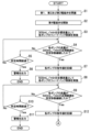
- FIG. 5 is a flowchart showing the liquid supply pump drive control operation.
- a command value for the target flow rate is calculated based on the proportional relational expression of the liquid supply pump 63 obtained in the calibration operation (S31).
- the liquid supply pump 63 is driven by feedforward control based on the calculated command value (S32).
- the drive control of the liquid supply pump 63 is switched from feedforward control to feedback control (S34). . This completes the operation.
- the drain pump drive control operation is an operation to control the drive of the drain pump 72 so that the flow rate of the drain pump 72 becomes a target flow rate, and as shown in FIG. Feedforward control is performed until a predetermined time period that is estimated to reach the target flow rate has elapsed with feedforward control that is not based on the value, and after the predetermined time elapses, the feedforward control is performed based on the detected value of the discharge side control flowmeter 73. This is to switch to feedback control.
- a command value for the target flow rate calculated based on the proportional relational expression obtained in the calibration operation is used as a command value for feedforward control.
- FIG. 6 is a flowchart showing the drainage pump drive control operation.
- a command value for the target flow rate is calculated based on the proportional relational expression of the drain pump 72 obtained in the calibration operation (S41).
- the drain pump 72 is driven by feedforward control based on the calculated command value (S42).
- the drive control of the drain pump 72 is switched from feedforward control to feedback control (S44). This completes this operation.
- the blood purification device 1 includes a startup process, a treatment preparation process, a patient puncture/blood removal process, a treatment process, a treatment interruption process, a patient needle removal/blood return process, a drainage process, a cleaning/disinfection process, a standby process, and an adjustment process. is executed.
- the calibration operation is performed during self-diagnosis in the startup process and during the adjustment process.
- the fluid supply pump drive control operation includes the startup of the fluid supply pump 63 in the startup process, the return of the fluid supply pump 63 in the treatment interruption process, the preparation process, the patient needle removal/blood return process, the treatment process, and the patient needle removal process.
- the liquid supply pump drive control operation described above is executed as the control operation of the liquid supply pump 63.
- the liquid supply pump drive control operation is performed to switch to feedback control after performing feedforward control, thereby controlling the flow rate of the liquid supply pump 63. It is possible to shorten the time it takes for the flow rate to reach around the target flow rate, and it is also possible to suppress flow rate fluctuations due to feedback control.
- the drainage pump drive control operation includes a startup process, a treatment preparation process, a patient puncture/blood removal process, a treatment process, a treatment interruption process, a patient needle removal/blood return process, a cleaning/disinfection process, a standby process, and an adjustment process.
- This is executed when the third electromagnetic valve 76 in the open state is closed.
- the drainage pump drive control operation starts from a state in which the third solenoid valve 76 is opened to communicate the dialysate discharge flow path 53 and the second bypass flow path 75, to a state in which the third solenoid valve 76 is closed and the dialysate is dialyzed. This is executed when the liquid discharge channel 53 and the second bypass channel 75 are placed in a non-communicating state.
- the control unit 22 controls the draining state.
- the above-mentioned drain pump drive control operation is executed.
- the drain pump 72 can be driven without being affected by the detection error of the discharge side control flow meter 73. Note that a configuration may be adopted in which feedforward control is performed when the third solenoid valve 76 is open, and when the third solenoid valve 76 is closed, the feedforward control is switched to feedback control.
- the temperature adjustment of the dialysate by the temperature adjustment means (not shown) and the concentration adjustment in the dialysate preparation unit 51 are performed simultaneously with the flow rate adjustment by the pumps 63 and 72, so that these feedback controls are performed mutually. , and large-amplitude disturbances are likely to occur.
- the drive control operation described above can prevent or suppress the occurrence of large-amplitude disturbances. Thereby, pressure fluctuations in the dialysate circuit 41 can be suppressed, so that not only the load on the piping of the dialysate circuit 41 but also the load on the dialyzer 10 and the load on the patient C can be suppressed.
- the second bypass flow path 75 when switching the communication of the second bypass flow path 75, by performing the drain pump drive control operation to switch to feedback control after performing feedforward control, the second bypass flow path 75 It is not affected by the detection error of the discharge side control flowmeter 73 that occurs when the passage 75 is switched for communication. Thereby, stable flow rate control can be performed even when switching the communication of the second bypass channel 75.
- a calibration operation is performed to obtain a proportional relational expression between the flow rate of the pumps 63 and 72 and the command value, and feedforward control is performed using the command value based on this. Control can be performed with high precision.
- the feed forward control in the supply pump drive control operation and the drain pump drive control operation, is switched to the feedback control on the condition that a predetermined time has elapsed.
- it may be configured to switch from feedforward control to feedback control.
- the feedforward control is changed to the feedback control. It may be configured to switch to.
- the control unit 22 performs feedforward control until the flow rate reaches a predetermined vicinity range of the target flow rate, and the control unit 22 performs feedforward control until the flow rate reaches a predetermined vicinity range of the target flow rate. It may be configured to switch from feedforward control to feedback control after reaching . In such a case, for example, as shown in FIG. 7, instead of the step (S33) of determining whether a predetermined period of time has elapsed, the flow rate of the liquid supply pump 63 may be monitored by a flow rate detection unit such as a flow meter 64 for controlling the supply side.
- a step (S51) of determining whether the flow rate of the liquid supply pump 63 has reached a predetermined vicinity range of the target flow rate is performed.
- a predetermined vicinity range of the target flow rate for example, a range of ⁇ 10% of the target flow rate
- feedforward control is switched to feedback control.
- FIG. 7 shows an example of the liquid supply pump drive control operation, in the case of the drain pump drive control operation, the process of S43 in FIG.
- the flow rate of the drain pump 72 is monitored, and the process is changed to a step in which it is determined whether the flow rate of the drain pump 72 has reached a predetermined vicinity range of the target flow rate (for example, a range of ⁇ 10% of the target flow rate).
- a predetermined vicinity range of the target flow rate for example, a range of ⁇ 10% of the target flow rate.
- a configuration may be adopted in which both time and flow rate are monitored, and when either the time condition or the flow rate condition is satisfied, the feedforward control is switched to the feedback control.
- the proportional relational expression was calculated based on the command values for two flow rates, the command value for the flow rate of 300 mL/min and the command value for the flow rate of 500 mL/min.
- the configuration is not limited to this, as long as command values for a plurality of mutually different flow rates are acquired and a proportional relational expression is calculated based on the acquired command values for the plurality of flow rates. That is, in the calibration operation, command values for three or more flow rates may be acquired, and a proportional relational expression may be calculated based on these command values.
- feedforward control and feedback control may be combined as desired without departing from the spirit of the present invention.
- it may be switched to feedforward control, and then switched to feedback control again.
- the control operation may be temporarily interrupted from feedforward control and then switched to feedback control.
- a blood purification device (1) that performs blood purification treatment via a blood purifier (10) that purifies the blood of a patient (C), which supplies dialysate to the blood purifier (10) and A dialysate circuit (41) that discharges the dialysate from the blood purifier (10); and a dialysate circuit (41) that is disposed in the dialysate circuit (41) and that transports the dialysate in the dialysate circuit (41).
- a liquid pump (63, 72); a drive control section (22) that executes a drive control operation to control the liquid pump (63, 72) so that the flow rate of the liquid pump (63) becomes a target flow rate; , a flow rate detection unit (64, 73) that detects the flow rate of the liquid feeding pump (63, 72), and in the drive control operation, the feed rate is not based on the detected value of the flow rate detection unit (64, 73).
- a blood purification device (1) that performs forward control and switches from the feedforward control to feedback control based on the detected value of the flow rate detection section (64, 73) on the condition that a predetermined time elapses or a predetermined flow rate is reached.
- the dialysate circuit (41) includes a dialysate supply channel (52) that supplies dialysate before use to the blood purifier (10), and a dialysate supply flow path (52) that supplies dialysate before use to the blood purifier (10), and a dialysate supply flow path (52) that supplies dialysate before use to the blood purifier (10). a dialysate discharge channel (53) for discharging dialysate; and a first fluid pump disposed in the dialysate supply channel (52) as the fluid pump (63, 72).
- the drive control section (22) includes a first fluid pump (72) disposed in the dialysate discharge channel (53).
- 63) is started, when the first liquid feeding pump (63) returns, and/or when changing the target flow rate of the first liquid feeding pump (63), the first liquid feeding pump (63)
- the blood purification device (1) according to ⁇ 1>>, which executes the drive control operation as a control operation of the pump (63). This makes it possible to shorten the time it takes for the flow rate of the liquid pump to reach around the target flow rate when the liquid pump starts, returns, or changes the target flow rate, and also suppresses fluctuations in the liquid pump's flow rate. can do.
- the dialysate circuit (41) includes a dialysate supply channel (52) that supplies dialysate before use to the blood purifier (10), and a dialysate supply flow path (52) that supplies dialysate before use to the blood purifier (10), and a dialysate supply flow path (52) that supplies dialysate before use to the blood purifier (10).
- a dialysate discharge channel (53) for discharging dialysate; a bypass channel (75) connected to the dialysate discharge channel (53) and releasing the pressure of the dialysate discharge channel (53); A communicating state in which the bypass channel (75) communicates with the dialysate discharge channel (53), and a non-communicating state in which the bypass channel (75) does not communicate with the dialysate discharge channel (53). and a solenoid valve (76) that switches the flow path state between the dialysing fluid supply flow path (52) and the dialysate supply flow path (52).
- the drive control unit (22) includes a liquid feeding pump (63) and a second liquid feeding pump (72) disposed in the dialysate discharge flow path (53), and the drive control unit (22) ), the blood purification device (1) according to ⁇ 1>> executes the drive control operation as a control operation of the second liquid feeding pump (72) when switching from the communication state to the non-communication state by .
- the liquid pump can be controlled without being affected by detection errors of the flowmeter that occur when switching the bypass channel for communication.
- ⁇ 4>> Further comprising a calibration section (22) that acquires calibration information that associates the command value for the liquid feeding pump (63, 72) with the flow rate, and in the feedforward control, the calibration section (22)
- the blood purification device (1) according to any one of ⁇ 1>> to ⁇ 3>>, wherein the liquid feeding pump (63, 72) is controlled by a command value based on the acquired calibration information. Thereby, feedforward control can be performed with high precision.
- the calibration unit (22) executes the feedback control on the liquid feeding pump (63, 72) using a plurality of mutually different flow rates as target flow rates, so that the liquid is fed at the plurality of flow rates.
- the blood purification device (1) according to ⁇ 4>> which calculates a relational expression. Thereby, feedforward control can be performed with higher accuracy.
- the calibration unit (22) determines whether or not there is an abnormality in the liquid feeding pump (63, 72) or the flow rate detection unit (64, 73) based on whether the calculated relational expression is correct or not. Blood purification device (1) according to item 5. This allows abnormality determination to be made during the calibration operation, making it easy to detect abnormalities.
- the calibration unit (22) The blood purification device (1) according to ⁇ 5> or ⁇ 6>, wherein it is determined that there is an abnormality in the liquid feeding pump (63, 72) or the flow rate detection section (64, 73). This allows abnormality determination to be made during the calibration operation, making it easy to detect abnormalities.
- ⁇ 8> Control the liquid pump (63, 72) disposed in the dialysate circuit (41) of the blood purification device (1) so that the flow rate of the liquid pump (63, 72) reaches the target flow rate.
Landscapes
- Health & Medical Sciences (AREA)
- Engineering & Computer Science (AREA)
- Urology & Nephrology (AREA)
- Heart & Thoracic Surgery (AREA)
- Anesthesiology (AREA)
- Life Sciences & Earth Sciences (AREA)
- General Engineering & Computer Science (AREA)
- Vascular Medicine (AREA)
- Mechanical Engineering (AREA)
- Biomedical Technology (AREA)
- Hematology (AREA)
- Emergency Medicine (AREA)
- Animal Behavior & Ethology (AREA)
- General Health & Medical Sciences (AREA)
- Public Health (AREA)
- Veterinary Medicine (AREA)
- Physics & Mathematics (AREA)
- Fluid Mechanics (AREA)
- External Artificial Organs (AREA)
Priority Applications (2)
| Application Number | Priority Date | Filing Date | Title |
|---|---|---|---|
| EP23830931.4A EP4523715A4 (en) | 2022-06-28 | 2023-05-29 | BLOOD PURIFICATION DEVICE AND METHOD FOR CONTROLLING A LIQUID SUPPLY PUMP |
| CN202380050235.9A CN119451713A (zh) | 2022-06-28 | 2023-05-29 | 血液净化装置以及送液泵的控制方法 |
Applications Claiming Priority (2)
| Application Number | Priority Date | Filing Date | Title |
|---|---|---|---|
| JP2022-103781 | 2022-06-28 | ||
| JP2022103781A JP2024004224A (ja) | 2022-06-28 | 2022-06-28 | 血液浄化装置及び送液ポンプの制御方法 |
Publications (1)
| Publication Number | Publication Date |
|---|---|
| WO2024004481A1 true WO2024004481A1 (ja) | 2024-01-04 |
Family
ID=89382669
Family Applications (1)
| Application Number | Title | Priority Date | Filing Date |
|---|---|---|---|
| PCT/JP2023/019908 Ceased WO2024004481A1 (ja) | 2022-06-28 | 2023-05-29 | 血液浄化装置及び送液ポンプの制御方法 |
Country Status (4)
| Country | Link |
|---|---|
| EP (1) | EP4523715A4 (https=) |
| JP (1) | JP2024004224A (https=) |
| CN (1) | CN119451713A (https=) |
| WO (1) | WO2024004481A1 (https=) |
Families Citing this family (1)
| Publication number | Priority date | Publication date | Assignee | Title |
|---|---|---|---|---|
| JP1780475S (ja) * | 2024-02-29 | 2024-09-24 | アクチュエータ用連結器 |
Citations (5)
| Publication number | Priority date | Publication date | Assignee | Title |
|---|---|---|---|---|
| JPS6399870A (ja) * | 1986-10-16 | 1988-05-02 | 横河電機株式会社 | 人工透析装置 |
| JP2002206804A (ja) * | 2001-01-11 | 2002-07-26 | Denso Corp | 給湯装置 |
| JP2006100152A (ja) * | 2004-09-30 | 2006-04-13 | Toyota Motor Corp | 燃料電池システム及びその検査システム |
| JP2011085984A (ja) * | 2009-10-13 | 2011-04-28 | Yokogawa Electric Corp | バルブ制御装置およびバルブ制御方法 |
| WO2020137190A1 (ja) | 2018-12-28 | 2020-07-02 | 日機装株式会社 | 血液浄化装置 |
Family Cites Families (5)
| Publication number | Priority date | Publication date | Assignee | Title |
|---|---|---|---|---|
| FR2597753B1 (fr) * | 1986-04-25 | 1990-09-28 | Hospal Ind | Rein artificiel avec dispositif de controle des quantites de liquide circulant dans le circuit de liquide de dialyse |
| US20070007184A1 (en) * | 2005-07-07 | 2007-01-11 | Delphi Technologies, Inc. | Specialized sensor-assisted dialysis |
| US8123947B2 (en) * | 2007-10-22 | 2012-02-28 | Baxter International Inc. | Priming and air removal systems and methods for dialysis |
| EP3104906B1 (en) * | 2014-02-11 | 2024-08-14 | Smiths Medical ASD, Inc. | Pump startup algorithms and related systems and methods |
| KR20210120735A (ko) * | 2020-03-27 | 2021-10-07 | 영남대학교 산학협력단 | 실린지 펌프 및 그 제어 방법 |
-
2022
- 2022-06-28 JP JP2022103781A patent/JP2024004224A/ja active Pending
-
2023
- 2023-05-29 CN CN202380050235.9A patent/CN119451713A/zh active Pending
- 2023-05-29 WO PCT/JP2023/019908 patent/WO2024004481A1/ja not_active Ceased
- 2023-05-29 EP EP23830931.4A patent/EP4523715A4/en active Pending
Patent Citations (5)
| Publication number | Priority date | Publication date | Assignee | Title |
|---|---|---|---|---|
| JPS6399870A (ja) * | 1986-10-16 | 1988-05-02 | 横河電機株式会社 | 人工透析装置 |
| JP2002206804A (ja) * | 2001-01-11 | 2002-07-26 | Denso Corp | 給湯装置 |
| JP2006100152A (ja) * | 2004-09-30 | 2006-04-13 | Toyota Motor Corp | 燃料電池システム及びその検査システム |
| JP2011085984A (ja) * | 2009-10-13 | 2011-04-28 | Yokogawa Electric Corp | バルブ制御装置およびバルブ制御方法 |
| WO2020137190A1 (ja) | 2018-12-28 | 2020-07-02 | 日機装株式会社 | 血液浄化装置 |
Non-Patent Citations (1)
| Title |
|---|
| See also references of EP4523715A4 |
Also Published As
| Publication number | Publication date |
|---|---|
| CN119451713A (zh) | 2025-02-14 |
| JP2024004224A (ja) | 2024-01-16 |
| EP4523715A4 (en) | 2026-04-15 |
| EP4523715A1 (en) | 2025-03-19 |
Similar Documents
| Publication | Publication Date | Title |
|---|---|---|
| US9364597B2 (en) | Blood ultrafiltration substitution target method and device | |
| WO2004014463A1 (ja) | 血液浄化装置およびその運転方法 | |
| SE523610C2 (sv) | Metod vid styrning av dialysanordning | |
| JP7051302B2 (ja) | 体外血液処理装置 | |
| JP6579896B2 (ja) | フィードフォワード制御を用いた、体外血液治療時における柔軟なクエン酸抗凝血用のためのシステム | |
| WO2024004481A1 (ja) | 血液浄化装置及び送液ポンプの制御方法 | |
| JP2004049493A (ja) | 血液透析装置および血液透析装置の制御プログラム | |
| US10821216B1 (en) | Method and apparatus for a hemodiafiltration module for use with a dialysis machine | |
| US20250381330A1 (en) | Blood purification device, and method for determining detection defect in flow meter | |
| JP7531073B2 (ja) | 血液浄化装置及び送液ポンプの制御方法 | |
| EP3437672A1 (en) | Blood purification system and method for priming of same | |
| JP2008093193A (ja) | 血液透析装置における逆濾過透析液の送液方法および血液透析装置 | |
| WO2024232210A1 (ja) | 医療用ポンプユニットおよび血液浄化装置 | |
| JP2024004224A5 (https=) | ||
| WO2005115498A1 (ja) | 間欠的に注液、除水操作を繰り返す血液透析装置 | |
| JP7484933B2 (ja) | 血液浄化装置 | |
| JP7363904B2 (ja) | 血液浄化装置 | |
| JP7790230B2 (ja) | 血液浄化装置 | |
| US20250269099A1 (en) | Method for Operating Blood Treatment System and Corresponding Blood Treatment System | |
| JP7797934B2 (ja) | 血液浄化装置 | |
| JP7775736B2 (ja) | 血液浄化装置 | |
| JP7592518B2 (ja) | 血液浄化装置 | |
| JP2024075976A (ja) | 血液浄化装置 | |
| WO2024150754A1 (ja) | 血液浄化装置 | |
| JP2024101622A (ja) | 血液浄化装置 |
Legal Events
| Date | Code | Title | Description |
|---|---|---|---|
| 121 | Ep: the epo has been informed by wipo that ep was designated in this application |
Ref document number: 23830931 Country of ref document: EP Kind code of ref document: A1 |
|
| WWE | Wipo information: entry into national phase |
Ref document number: 2023830931 Country of ref document: EP |
|
| ENP | Entry into the national phase |
Ref document number: 2023830931 Country of ref document: EP Effective date: 20241212 |
|
| WWE | Wipo information: entry into national phase |
Ref document number: 202380050235.9 Country of ref document: CN |
|
| NENP | Non-entry into the national phase |
Ref country code: DE |
|
| WWP | Wipo information: published in national office |
Ref document number: 202380050235.9 Country of ref document: CN |