WO2024004171A1 - ロボット制御装置及びロボット制御システム - Google Patents
ロボット制御装置及びロボット制御システム Download PDFInfo
- Publication number
- WO2024004171A1 WO2024004171A1 PCT/JP2022/026382 JP2022026382W WO2024004171A1 WO 2024004171 A1 WO2024004171 A1 WO 2024004171A1 JP 2022026382 W JP2022026382 W JP 2022026382W WO 2024004171 A1 WO2024004171 A1 WO 2024004171A1
- Authority
- WO
- WIPO (PCT)
- Prior art keywords
- robot
- control device
- robot control
- value
- failure
- Prior art date
- Legal status (The legal status is an assumption and is not a legal conclusion. Google has not performed a legal analysis and makes no representation as to the accuracy of the status listed.)
- Ceased
Links
Images







Classifications
-
- B—PERFORMING OPERATIONS; TRANSPORTING
- B25—HAND TOOLS; PORTABLE POWER-DRIVEN TOOLS; MANIPULATORS
- B25J—MANIPULATORS; CHAMBERS PROVIDED WITH MANIPULATION DEVICES
- B25J9/00—Program-controlled manipulators
- B25J9/16—Program controls
- B25J9/1656—Program controls characterised by programming, planning systems for manipulators
-
- B—PERFORMING OPERATIONS; TRANSPORTING
- B25—HAND TOOLS; PORTABLE POWER-DRIVEN TOOLS; MANIPULATORS
- B25J—MANIPULATORS; CHAMBERS PROVIDED WITH MANIPULATION DEVICES
- B25J9/00—Program-controlled manipulators
- B25J9/16—Program controls
- B25J9/1628—Program controls characterised by the control loop
- B25J9/163—Program controls characterised by the control loop learning, adaptive, model based, rule based expert control
-
- G—PHYSICS
- G05—CONTROLLING; REGULATING
- G05B—CONTROL OR REGULATING SYSTEMS IN GENERAL; FUNCTIONAL ELEMENTS OF SUCH SYSTEMS; MONITORING OR TESTING ARRANGEMENTS FOR SUCH SYSTEMS OR ELEMENTS
- G05B2219/00—Program-control systems
- G05B2219/30—Nc systems
- G05B2219/39—Robotics, robotics to robotics hand
- G05B2219/39529—Force, torque sensor in wrist, end effector
-
- G—PHYSICS
- G05—CONTROLLING; REGULATING
- G05B—CONTROL OR REGULATING SYSTEMS IN GENERAL; FUNCTIONAL ELEMENTS OF SUCH SYSTEMS; MONITORING OR TESTING ARRANGEMENTS FOR SUCH SYSTEMS OR ELEMENTS
- G05B2219/00—Program-control systems
- G05B2219/30—Nc systems
- G05B2219/40—Robotics, robotics mapping to robotics vision
- G05B2219/40504—Simultaneous trajectory and camera planning
Definitions
- the present invention relates to a robot control device and a robot control system that control a robot.
- the robot teaching work is an essential work to make the robot perform a predetermined operation.
- the spread of robots not only highly skilled workers but also less skilled workers have to teach robots.
- the task of teaching them becomes more complex. Therefore, a robot teaching assist device has been proposed that has a function of assisting a worker in teaching a robot (Patent Document 1).
- a robot control device is a computer device that controls a robot equipped with a sensor.
- the robot control device includes: a storage unit that stores parameters for setting robot operations in association with index values representing operating states in which the robot operates according to the parameters; and a search unit that searches for parameters based on the index values.
- a display unit that displays the searched parameters.
- FIG. 1 is a perspective view showing a robot device including a robot control device according to this embodiment.
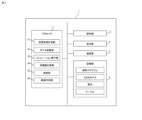
- FIG. 2 is a functional block diagram of the robot control device according to this embodiment.
- FIG. 3 is a diagram showing an example of a mathematical formula stored in the storage section of FIG. 2.
- FIG. 4 is a diagram showing an example of a setting history management table stored in the storage section of FIG. 2.
- FIG. 5 is a diagram illustrating an example of an allocation table related to operational abnormalities stored in the storage unit of FIG. 2.
- FIG. 6 is a diagram illustrating an example of an assignment table regarding success or failure of an operation stored in the storage unit of FIG. 2.
- FIG. 7 is a diagram showing an example of a weighting coefficient management table stored in the storage section of FIG. 2.
- FIG. 8 is a diagram showing an example of a search screen displayed on the display section of FIG. 2.
- FIG. 9 is a diagram showing an example of a simulation screen displayed on the display section of FIG. 2.
- the robot control device has a function of storing operation parameters for setting the operation of the robot in association with an index value (hereinafter sometimes simply referred to as an index value) representing the operation state of the robot;
- This computer device has a function of searching for an operating parameter based on an index value and a function of displaying the searched operating parameter.
- index value representing the operating state of the robot is a numerical value that represents the state of the robot during operation and the result of the robot's operation according to a predetermined rule.
- index values representing the operating state of the robot are derived based on the cycle time of the robot, the torque value applied to the robot during operation, the presence or absence of an overheat alarm, and the degree of success or failure of the robot's operation. be done.
- index values representing the robot's operating status are derived not only from quantitative data such as cycle time and torque values, but also from qualitative data such as the presence or absence of overheat alarms and the success or failure of operations. The results are comprehensively derived, including relevant data.
- the motion speed which is the setting information of the moving speed of the hand reference point
- the motion parameter is not limited to this.
- various parameters that cause changes in motion can be employed as motion parameters. More specifically, standby time, interpolation format, movement format, etc. can be employed as operation parameters.
- the standby time is a period of time when a standby command is written in the operation program.
- the interpolation format is a condition regarding the interpolation format between two teaching points.
- the interpolation format includes circular interpolation, linear interpolation, and the like.
- the movement format is a condition regarding how to move between a plurality of teaching points.
- the movement format includes a format in which the robot is moved so as to always pass through the teaching point, a format in which it is moved smoothly so as to pass through the teaching point or its vicinity without necessarily passing through the teaching point, and the like.
- the index value is not limited to the above four types of data.
- the index value can be calculated using at least one type of data among the above four types of data.
- the torque value based on the output of the force sensor is used as the sensor data used to calculate the index value, but the sensor data is not limited to this.
- any value based on the output of any sensor installed on the robot can be used to calculate the index value, such as acceleration based on the output of an acceleration sensor installed on the robot, speed based on the output of a speed sensor, etc. .
- overheating is used as an example of the operational abnormality used for calculating the index value, but the type of operational abnormality is not limited to this. For example, sudden acceleration, excessive speed, vibration, etc. can be adopted as the abnormal operation. Further, the number of operational abnormalities is not limited to one, and may be multiple.
- the action was successful there are two types of degrees representing success or failure of an action: "the action was successful” and “the action was not successful”, but the degree is not limited to this.
- “the motion was successful” may be divided into “successful with stable motion” and “successful with unstable motion”.
- “the motion was not successful” may be divided into "it seems likely that the robot will succeed if the robot's motion is slightly improved” and “it will not be successful unless the robot's motion is greatly improved”.
- the degree of success or failure of the operation may be divided into five levels, with a completely successful state being set as "5" and a completely failed state being set as "1".
- the degree of success or failure of the movement is input into the robot control device through a user operation.
- the degree of success or failure of an action is expressed in two ways: “the action was successful” and “the action was not successful”, it can also be identified based on the outputs of various sensors equipped on the robot. .
- the robot control device 1 will be described below.
- the robot control device 1 according to the present embodiment and the robot 8 constitute a robot device 7.
- the robot 8 includes a force sensor 9 for detecting the load applied to the end effector. Output data from a force sensor 9 equipped on the robot 8 is input to the robot control device 1.
- the sensor 9 equipped on the robot 8 is not limited to the force sensor 9.
- the robot 8 includes a vision camera for photographing the workpiece W, an encoder for detecting the rotational position of a motor, an infrared sensor for detecting the presence or absence of a worker or an obstacle, a contact sensor for detecting the presence or absence of contact by a worker, etc. may be provided.
- the robot control device 1 As shown in FIG. 2, in the robot control device 1 according to the present embodiment, hardware such as an operation section 3, a display section 4, a communication section 5, and a storage section 6 are connected to a processor 2 (such as a CPU). It consists of The robot control device 1 is provided by a general information processing terminal such as a personal computer or a tablet.
- the operation unit 3 has input devices such as a keyboard, a mouse, and a jog.
- the input device may be provided by a touch panel that also serves as the display unit 4, or may be provided by a dedicated operating device (pendant) of the robot control device 1.
- a user can input various information to the robot control device 1 via the operation unit 3.
- the display unit 4 has a display device such as an LCD, and displays the search screen 100, simulation screen 200, etc. created by the screen creation unit 26.
- the communication unit 5 controls data transmission and reception with the robot 8. Through the processing of the communication unit 5, the robot control device 1 receives output data from the force sensor 9 installed on the robot 8.
- the storage unit 6 includes a storage device such as an HDD or an SSD.
- the storage unit 6 stores a search program for searching operating parameters, data of a three-dimensional model displayed on the simulation screen 200, data of a plurality of types of mathematical formulas, and data of a plurality of types of tables.
- the three-dimensional model data includes data on a three-dimensional model of the robot 8 including the force sensor 9, and data on a three-dimensional model of the workpiece.
- three-dimensional model data is provided by CAD data.
- the formulas include a cycle time conversion formula, a torque value conversion formula, an index value calculation formula, etc.
- the cycle time conversion formula is a calculation formula for converting the cycle time into a value for calculating an index value.
- the multiple types of tables include a setting history management table for managing previously set operating speeds, an assignment table for assigning numerical values to the presence or absence of an overheat alarm (referred to as an assignment table for operating abnormalities), and a table for indicating the success or failure of an operation. It includes an assignment table for assigning numerical values to degrees (referred to as an assignment table for success/failure of actions), and a weighting coefficient management table for managing weighting coefficients used for calculating index values.
- FIG. 4 shows an example of a setting history management table.
- one record in the setting history management table contains item number, setting date and time, operation program name, operation speed, cycle time, torque value, presence or absence of overheat alarm, success or failure of operation, index value, and countermeasure. The method is controlled.
- One record in the setting history management table is called a setting history.
- the operating program name, operating speed, and countermeasure method are registered based on user input information.
- the cycle time, torque value, presence or absence of an overheat alarm, success or failure of the operation, and index values are automatically registered by the internal processing of the robot control device 1.
- part of the cycle time, torque value, presence or absence of an overheat alarm, success or failure of operation, and index value may be input by the user.
- the motion speed is an example of a motion parameter, and is a parameter that sets the movement speed of the hand reference point.
- the cycle time corresponds to the time actually taken from the start of the operation to the end of the operation when the robot 8 is caused to execute a series of operations specified in the operation program.
- the torque value corresponds to the maximum torque value applied to the robot 8 during operation, which is calculated based on the output of the force sensor 9 equipped on the robot 8.
- An overheat alarm is generated when the motor is running at high RPMs, when the motor is running at severe cycles, or when the actual temperature of the motor or its surroundings is high. The success or failure of the operation indicates whether or not the robot 8 was able to successfully execute a series of operations specified in the operation program.
- Normal here indicates that a series of operations specified in the operation program could be executed within the specified time.
- the robot 8 temporarily stops during operation, and is unable to complete a series of operations specified in the operation program within a specified time.
- the operation specified in the operation program has failed. In these cases, the success or failure of the operation is "fail”.
- FIG. 5 shows an example of an allocation table related to operational abnormalities.
- overheating is adopted as an operational abnormality, and a numerical value is assigned to each of the presence or absence of overheating.
- the degree of overheating may be divided into three or more levels and a numerical value may be assigned to each level.
- multiple types of operational abnormalities may be included.
- the operational abnormalities include important operational abnormalities that are related to the success or failure of the operation, and minor operational abnormalities that are not related to the success or failure of the operation. Therefore, the numerical value assigned may be different depending on the type of abnormal operation.
- FIG. 6 shows an example of an assignment table regarding the success or failure of an operation.
- a numerical value is associated with each success or failure of the action.
- the numerical value D "1" is assigned to the success or failure of the operation "successful", and the numerical value D "0" is assigned to "not successful (failure)".
- this assigned value is initially determined as described above, it can be changed as appropriate according to user operations.
- “successful” and “unsuccessful” are used as degrees of success or failure of the operation, and numerical values are assigned to each.
- the degree of success or failure of the operation may be divided into three or more levels, and a numerical value may be assigned to each level.
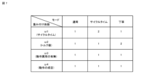
- FIG. 7 shows an example of the weighting coefficient management table.
- the weighting coefficient is a parameter for changing the degree of influence of cycle time, torque value, presence or absence of an overheat alarm, and success or failure of operation on the index value.
- the weighting coefficient corresponding to the cycle time is set to be larger than other weighting coefficients.
- the weighting coefficient ⁇ 1 corresponding to the cycle time is "2”
- the weighting coefficient ⁇ 2 corresponding to the torque value is "1”
- the weighting coefficient ⁇ 3 corresponding to the presence or absence of abnormal operation is "1”
- the weighting coefficient ⁇ 3 corresponding to the presence or absence of operation abnormality is "1”.
- the weighting coefficient ⁇ 4 corresponding to success or failure is set to “1”.
- the weighting coefficient corresponding to the torque value is set to be larger than other weighting coefficients.
- the weighting coefficient ⁇ 1 corresponding to the cycle time is "1”
- the weighting coefficient ⁇ 2 corresponding to the torque value is "2”
- the weighting coefficient ⁇ 3 corresponding to the presence or absence of abnormal operation is "1”
- the weighting coefficient ⁇ 3 corresponding to the presence or absence of abnormal operation is "1”.
- the weighting coefficient ⁇ 4 corresponding to success or failure is set to “1”.
- the robot control device 1 when the search program stored in the storage unit 6 is executed by the processor 2, the robot control device 1 includes a virtual space creation unit 21, a model placement unit 22, a simulation execution unit 23, an index It functions as a value calculation section 24, a search section 25, and a screen creation section 26.
- the virtual space creation unit 21 creates a virtual space on software that three-dimensionally represents the operation space in which the robot operates.
- the virtual space created by the virtual space creation section 21 is displayed on a simulation screen 200 created by the screen creation section 26.
- the model placement unit 22 places a three-dimensional model 8′ (robot model 8′) of the robot 8 and a three-dimensional model W′ ( A work model W') is placed.
- the robot model 8' and the workpiece model W' are arranged in the virtual space so as to correspond to the positional relationship between the robot 8 and the workpiece W in the actual operation space.
- the simulation execution unit 23 executes a simulation operation in which the robot model 8' in the virtual space displayed on the simulation screen 200 is moved in a simulated manner according to the operation program and operation speed, or according to a user instruction via the operation unit 3.
- the robot model 8' displayed on the simulation screen 200 can be operated according to the operation speed selected by the user.
- the setting history is associated with the point in time during the operation when an event that caused the operation to be unsuccessful occurred or when an overheat alarm was issued.
- the user can check the event that caused the operation to be unsuccessful based on the position and posture of the robot 8 at that time, and can modify the operation of the robot 8 so that the operation is successful.
- the index value calculation unit 24 calculates an index value representing the operating state of the robot. Typically, the index value calculation unit 24 converts the cycle time a into a converted value A using the cycle time conversion formula shown in FIG. 3, and converts the torque value b into a converted value B using the torque value conversion formula. Convert to . Further, with reference to the assignment table shown in FIG. 5, a numerical value C is assigned to the presence or absence of an overheat alarm. Referring to the assignment table shown in FIG. 6, a numerical value D is assigned to the success or failure of the operation. Further, referring to FIG. 7, weighting coefficients ⁇ 1, ⁇ 2, ⁇ 3, and ⁇ 4 are specified based on important items input by the user.
- the index value calculation unit 24 substitutes the converted value A, the converted value B, the assigned value C, the assigned value D, and the weighting coefficients ⁇ 1, ⁇ 2, ⁇ 3, ⁇ 4 into the formula for calculating the index value Iv shown in FIG. By doing so, the index value Iv is calculated.
- the method of calculating the index value is not limited to these methods.
- the search unit 25 searches the setting history management table and extracts the operating speed according to the search conditions input by the user's operation on the search screen 100. Typically, the search unit 25 searches the setting history management table and extracts the operating speed associated with the largest index value as the recommended operating speed.
- the method of searching the operating speed by the search unit 25 is not limited to this.
- the search unit 25 may search the setting history management table and extract a plurality of motion speeds in descending order of index value as the motion speeds to be presented.
- an operating speed that is close in value to the recommended operating speed and that is associated with an overheat alarm of "present" may be extracted as a reference operating speed.
- the screen creation unit 26 creates a search screen 100 for the user to search for a motion speed, and a simulation screen 200 for reproducing the robot's motion based on the motion speed selected by the user.
- the search screen 100 created by the screen creation section 26 will be explained with reference to FIG. 8.
- the search screen 100 includes a search condition display area 110 where search conditions are displayed, a search result display area 120 where search results are displayed, and a reproduction screen for transitioning from the search screen 100 to a simulation screen 200.
- a button 150 is included.
- a pull-down menu 112 is arranged in correspondence with the search condition "operating program name", and a pull-down menu 114 is arranged in correspondence with the search condition "important item (importance)”. ing.
- the search result display area 120 includes an area 130 that displays recommended operating speeds and an area 140 that displays operating speeds associated with the overheat alarm "present.”
- Area 130 displays the operation speed recommended for the search condition input by the user, as well as the index value associated with the operation speed, cycle time, torque value, presence or absence of an overheat alarm, and success or failure of the operation.
- the area 140 displays the operation speed of the setting history associated with the overheat alarm "present”, as well as the index value, cycle time, torque value, success or failure of the operation, and countermeasures taken to prevent overheating.
- check boxes 135, 145 are arranged for accepting an operation speed selection operation.
- the robot control device 1 uses the processing of the index value calculation unit 24 to set With reference to the history management table, a setting history associated with the operating program name "TEST1" is extracted, and an index value of the extracted setting history is calculated.
- the robot control device 1 converts the cycle time a using the cycle time conversion formula shown in FIG. 3, and converts the torque value b using the torque value conversion formula. For example, the cycle time “10s” of item number “1” is converted to numerical value A “12", the cycle time “20s” of item number “2” is converted to numerical value A “6”, and the cycle time of item number “3” is converted to numerical value A “6”. The cycle time “30s” is converted to the numerical value A "4", and the cycle time "25s" of item number "4" is converted to the numerical value A "4.8".
- the robot control device 1 refers to the assignment table regarding operational abnormalities shown in FIG. 5 and assigns a numerical value C to the presence or absence of an overheat alarm.
- the numerical value B "0" is assigned to the overheat alarm “present” of item numbers “1” and "2”
- the numerical value B "1” is assigned to the overheat alarm “absent” of the item numbers "3" and "4". It will be done.
- the robot control device 1 refers to the assignment table regarding the success or failure of the motion shown in FIG. 6 and assigns a numerical value D to the success or failure of the motion.
- a numerical value D assigns a numerical value to the success or failure of the motion.
- the numerical value "0" is assigned to the success or failure of the action of item numbers "1" and "2”
- the numerical value "1" is assigned to the success or failure of the action.
- the robot control device 1 calculates the index value Iv corresponding to the setting history by substituting numerical values A, B, C, D and weighting coefficients ⁇ 1, ⁇ 2, ⁇ 3, ⁇ 4 into the formula for calculating the index value Iv shown in FIG. is calculated.
- the index value "0" corresponds to item number "1”
- the index value "0" corresponds to item number "2”
- the index value "8” corresponds to item number "3”
- the index value "8” corresponds to item number "3”.
- An index value "9.6” corresponding to the number "4" is calculated.
- the robot control device 1 extracts the item number "4" with the largest index value through the processing of the search unit 25, and specifies the operating speed "400 mm/s” associated with the item number "4" as the recommended operating speed. do.
- the index value "9.6” associated with the operating speed "400 mm/s” along with the recommended operating speed "400 mm/s", the index value "9.6” associated with the operating speed "400 mm/s", the cycle time "25 s", and the torque value "72 N" " Overheat alarm "No” and success/failure of operation "Success" are displayed.
- the robot control device 1 determines that among the item numbers "1" and “2" associated with the overheat alarm "present", the recommended operation speed is "400 mm/s" and the cycle time "25 s” is selected. Extract item number “2" having a close cycle time "500 mm/s”. Then, the operating speed "500 mm/s” associated with item number "2” is specified as the operating speed associated with the overheat alarm "present”. As a result, as shown in Fig. 8, the setting history associated with the overheat alarm "present” includes the operating speed "500 mm/s", the index value "0", the cycle time "20 s", and the torque value "91 N”. The alarm “Yes” and the success or failure of the operation are displayed.
- the configuration of the search screen 100 is not limited to this embodiment.
- the index value, torque value, presence or absence of an overheat alarm, and success or failure of the operation are displayed together with the operating speed. It is also possible to display only the
- the operating speed associated with the overheat alarm "present” is displayed together with the recommended operating speed, but the user can at least understand the recommended operating speed. If possible, only the recommended operating speed may be displayed.
- only one recommended operating speed is displayed, but multiple operating speeds may be displayed in the recommended order. Furthermore, not one but a plurality of operating speeds associated with the overheat alarm "present” may be displayed. Furthermore, the motion speed associated with the success or failure of the motion may be displayed.
- the search item is selected from a pull-down menu, but a search field may be provided and the user can freely input search conditions into the search field.
- the simulation screen 200 created by the screen creation section 26 is displayed when the operation speed is selected by the user's operation on the check boxes 135 and 145 displayed on the search screen 100 shown in FIG. 8, and the reproduction button 150 is clicked.
- the simulation screen 200 displays a video display area 210 where a simulation video is displayed, a play/pause button 221, a rewind button 223, and a fast forward button 225 for operating the simulation video. and a return button 230 for returning to the search screen 100.
- a virtual space created by the virtual space creation section 21 and in which the robot model 8' and the work model W' are arranged by the model arrangement section 22 is displayed.
- the robot model 8' is moved by the processing of the simulation execution unit 23.
- the check box 145 corresponding to the operation speed associated with the overheat alarm "present" on the search screen 100, the user can check the operation of the robot 8 through simulation when the overheat alarm occurs. .
- the operating speed of the operating program is stored in association with an index value representing the operating state of the robot that operates according to the operating speed.
- the index value representing the operating state of the robot is a value obtained by quantifying the state of the robot during operation and the result of the robot's operation according to a predetermined rule.
- the predetermined rules include whether emphasis is placed on cycle time or careful movement.
- the robot control device 1 can calculate an index value that increases the degree of influence of cycle time. Thereby, the robot control device 1 can present the operation speed of the setting history with the largest calculated index value, that is, the cycle time is prioritized, as the recommended operation speed to the user who places importance on cycle time. Similarly, the robot control device 1 can calculate an index value that increases the degree of influence of the torque value. Thereby, the robot control device 1 can present the operation speed with the largest calculated index value, that is, the operation speed in the setting history that prioritizes the torque value, as the recommended operation speed to the user who emphasizes careful movement. .
- the robot control device 1 associates the motion speed with an index value representing the motion state of the robot 8 that operates according to the motion speed, and searches for the motion speed corresponding to the item desired by the user based on the index value. be able to.
- the robot control device 1 is generally deleted if the cycle time is too slow, the load on the robot 8 is too large, an abnormal operation occurs, the operation is not successful, etc.
- the operating speed of the robot 8 when the operation fails can be held as know-how together with the operating speed for which an appropriate value has been set. In this way, maintaining the operating speed when the operation of the robot 8 fails is also one of the important features of the robot control device 1 according to the present embodiment.
- the robot control device 1 can present to the user not only a motion speed set to an appropriate value, but also a motion speed set to an inappropriate value when the robot 8 fails in motion. Can be done. For example, if the information presented by the robot control device 1 is only the recommended motion speed, it is difficult for the user to change the motion speed. This is because even if the user can grasp the recommended operating speed, he or she cannot grasp how fast the operating speed can be increased. In such a case, the user needs to perform a test run of the robot 8 while changing the operating speed to understand how much the operating speed can be increased.
- the user can understand to what extent the operation speed must be increased before failure occurs, and how to deal with failure. Therefore, the user can examine the currently set motion speed in detail by referring not only to the recommended motion speed set in the past but also to the motion speed set in the past when the robot 8's motion failed. and can be determined.
- the worker can determine the operation parameters tried in the past, the cycle time, torque value, and the presence or absence of abnormal operation of the robot 8 that operates according to the operation parameters. and the success or failure of the operation can be grasped as know-how. Thereby, there is no need to trial run the robot 8 with the same operating parameters, and the teaching work can be performed efficiently.
- the robot control device 1 calculates one index value representing the operation state of the robot as a result of the operation.
- the robot control device 1 may calculate a plurality of index values corresponding to a plurality of time points while the robot 8 is operating according to the operation program.
- the temporal change in the index value it is possible to specify the point in time when the index value is low as the point in time when the operation has failed.
- the motion of the robot 8 at the time when the operation fails and the positional relationship with surrounding objects such as a workpiece can be displayed on the simulation screen 200, and the operator can visually check the simulation screen 200 and feel more intuitively. It is possible to understand the cause of failure.
- Robot control device 7... Robot device, 8... Robot, 9... Force sensor, 100... Search screen, 110... Search condition display area, 112, 114... Pull-down menu, 120... Search result display area, 130... Recommended Display area for operating speed, 140... Display area for operating speed associated with overheat alarm "present", 135, 145... Check box, 150... Reproduction button.
Landscapes
- Engineering & Computer Science (AREA)
- Robotics (AREA)
- Mechanical Engineering (AREA)
- Numerical Control (AREA)
- Manipulator (AREA)
Priority Applications (6)
| Application Number | Priority Date | Filing Date | Title |
|---|---|---|---|
| CN202280097094.1A CN119365305A (zh) | 2022-06-30 | 2022-06-30 | 机器人控制装置以及机器人控制系统 |
| DE112022007038.2T DE112022007038T5 (de) | 2022-06-30 | 2022-06-30 | Roboter-Steuervorrichtung und Roboter-Steuersystem |
| PCT/JP2022/026382 WO2024004171A1 (ja) | 2022-06-30 | 2022-06-30 | ロボット制御装置及びロボット制御システム |
| US18/875,167 US20250367822A1 (en) | 2022-06-30 | 2022-06-30 | Robot control device and robot control system |
| JP2024530230A JPWO2024004171A1 (https=) | 2022-06-30 | 2022-06-30 | |
| TW112122650A TW202402485A (zh) | 2022-06-30 | 2023-06-16 | 機器人控制裝置及機器人控制系統 |
Applications Claiming Priority (1)
| Application Number | Priority Date | Filing Date | Title |
|---|---|---|---|
| PCT/JP2022/026382 WO2024004171A1 (ja) | 2022-06-30 | 2022-06-30 | ロボット制御装置及びロボット制御システム |
Publications (1)
| Publication Number | Publication Date |
|---|---|
| WO2024004171A1 true WO2024004171A1 (ja) | 2024-01-04 |
Family
ID=89382547
Family Applications (1)
| Application Number | Title | Priority Date | Filing Date |
|---|---|---|---|
| PCT/JP2022/026382 Ceased WO2024004171A1 (ja) | 2022-06-30 | 2022-06-30 | ロボット制御装置及びロボット制御システム |
Country Status (6)
| Country | Link |
|---|---|
| US (1) | US20250367822A1 (https=) |
| JP (1) | JPWO2024004171A1 (https=) |
| CN (1) | CN119365305A (https=) |
| DE (1) | DE112022007038T5 (https=) |
| TW (1) | TW202402485A (https=) |
| WO (1) | WO2024004171A1 (https=) |
Citations (4)
| Publication number | Priority date | Publication date | Assignee | Title |
|---|---|---|---|---|
| JP2003150219A (ja) * | 2001-11-12 | 2003-05-23 | Fanuc Ltd | 作業機械のシミュレーション装置 |
| JP2008100315A (ja) * | 2006-10-19 | 2008-05-01 | Mitsubishi Heavy Ind Ltd | 制御シミュレーションシステム |
| JP2019188545A (ja) * | 2018-04-26 | 2019-10-31 | セイコーエプソン株式会社 | ロボット制御装置 |
| JP2022054043A (ja) * | 2020-09-25 | 2022-04-06 | セイコーエプソン株式会社 | ロボットの制御パラメーターに関する表示を行う方法、プログラム、および情報処理装置 |
Family Cites Families (2)
| Publication number | Priority date | Publication date | Assignee | Title |
|---|---|---|---|---|
| US9694494B1 (en) * | 2015-12-11 | 2017-07-04 | Amazon Technologies, Inc. | Feature identification and extrapolation for robotic item grasping |
| JP7107830B2 (ja) * | 2018-12-21 | 2022-07-27 | ファナック株式会社 | 学習用データ確認支援装置、機械学習装置、故障予知装置 |
-
2022
- 2022-06-30 WO PCT/JP2022/026382 patent/WO2024004171A1/ja not_active Ceased
- 2022-06-30 JP JP2024530230A patent/JPWO2024004171A1/ja active Pending
- 2022-06-30 DE DE112022007038.2T patent/DE112022007038T5/de active Pending
- 2022-06-30 CN CN202280097094.1A patent/CN119365305A/zh active Pending
- 2022-06-30 US US18/875,167 patent/US20250367822A1/en active Pending
-
2023
- 2023-06-16 TW TW112122650A patent/TW202402485A/zh unknown
Patent Citations (4)
| Publication number | Priority date | Publication date | Assignee | Title |
|---|---|---|---|---|
| JP2003150219A (ja) * | 2001-11-12 | 2003-05-23 | Fanuc Ltd | 作業機械のシミュレーション装置 |
| JP2008100315A (ja) * | 2006-10-19 | 2008-05-01 | Mitsubishi Heavy Ind Ltd | 制御シミュレーションシステム |
| JP2019188545A (ja) * | 2018-04-26 | 2019-10-31 | セイコーエプソン株式会社 | ロボット制御装置 |
| JP2022054043A (ja) * | 2020-09-25 | 2022-04-06 | セイコーエプソン株式会社 | ロボットの制御パラメーターに関する表示を行う方法、プログラム、および情報処理装置 |
Also Published As
| Publication number | Publication date |
|---|---|
| JPWO2024004171A1 (https=) | 2024-01-04 |
| US20250367822A1 (en) | 2025-12-04 |
| CN119365305A (zh) | 2025-01-24 |
| DE112022007038T5 (de) | 2025-02-20 |
| TW202402485A (zh) | 2024-01-16 |
Similar Documents
| Publication | Publication Date | Title |
|---|---|---|
| JP3946753B2 (ja) | ロボットプログラム評価・修正方法及びロボットプログラム評価・修正装置 | |
| JP2019171498A (ja) | ロボットプログラム実行装置、ロボットプログラム実行方法、プログラム | |
| WO2019064916A1 (ja) | ロボットシミュレータ | |
| US20220281103A1 (en) | Information processing apparatus, robot system, method of manufacturing products, information processing method, and recording medium | |
| JP7151713B2 (ja) | ロボットシミュレータ | |
| JP2023003731A (ja) | 情報処理装置、情報処理方法、表示装置、表示方法、ロボットシステム、物品の製造方法、プログラム及び記録媒体 | |
| JP2019053718A (ja) | 加工シミュレーション装置 | |
| WO2024004171A1 (ja) | ロボット制御装置及びロボット制御システム | |
| JP2005216213A (ja) | 故障診断システム及び故障診断方法 | |
| US20230109876A1 (en) | Information processing apparatus, information processing method, and method of manufacturing products | |
| JP2007136671A (ja) | ロボットプログラム評価・修正方法及びロボットプログラム評価・修正装置 | |
| US20220121163A1 (en) | Method for visualizing the automation of a technical system | |
| Mousavi Mohammadi et al. | A real-time impedance-based singularity and joint-limits avoidance approach for manual guidance of industrial robots | |
| JPH07200019A (ja) | ロボット制御装置 | |
| JP7328473B1 (ja) | 制御装置、産業機械のシステム、実行履歴データ表示方法、及びプログラム | |
| JP2023057024A (ja) | 情報処理装置、情報処理方法、物品の製造方法、プログラム、記録媒体、システム | |
| JP7633404B2 (ja) | ロボットの動作プログラムを管理する管理装置、ネットワークシステム、及び方法 | |
| JP7753049B2 (ja) | ロボットデータ処理サーバ及び軌跡データ算出方法 | |
| JP7710901B2 (ja) | 制御方法、制御装置、情報処理方法、情報処理装置、ロボット装置、物品の製造方法、プログラムおよび記録媒体 | |
| WO2023233623A1 (ja) | 情報処理装置 | |
| JP7818375B2 (ja) | ロボットデータ処理サーバ及び補正プログラム算出方法 | |
| WO2025262859A1 (ja) | 監視装置及び監視プログラム | |
| JP2025100202A (ja) | 支援装置 | |
| WO2025109958A1 (ja) | 同定方法、同定装置、及び同定プログラム | |
| WO2025135116A1 (ja) | 支援装置 |
Legal Events
| Date | Code | Title | Description |
|---|---|---|---|
| 121 | Ep: the epo has been informed by wipo that ep was designated in this application |
Ref document number: 22949444 Country of ref document: EP Kind code of ref document: A1 |
|
| WWE | Wipo information: entry into national phase |
Ref document number: 2024530230 Country of ref document: JP |
|
| WWE | Wipo information: entry into national phase |
Ref document number: 112022007038 Country of ref document: DE |
|
| WWE | Wipo information: entry into national phase |
Ref document number: 202280097094.1 Country of ref document: CN |
|
| WWE | Wipo information: entry into national phase |
Ref document number: 18875167 Country of ref document: US |
|
| WWP | Wipo information: published in national office |
Ref document number: 202280097094.1 Country of ref document: CN |
|
| WWP | Wipo information: published in national office |
Ref document number: 112022007038 Country of ref document: DE |
|
| 122 | Ep: pct application non-entry in european phase |
Ref document number: 22949444 Country of ref document: EP Kind code of ref document: A1 |
|
| WWP | Wipo information: published in national office |
Ref document number: 18875167 Country of ref document: US |