WO2023286814A1 - 定電位電解式ガスセンサおよび定電位電解式ガスセンサの製造方法 - Google Patents
定電位電解式ガスセンサおよび定電位電解式ガスセンサの製造方法 Download PDFInfo
- Publication number
- WO2023286814A1 WO2023286814A1 PCT/JP2022/027605 JP2022027605W WO2023286814A1 WO 2023286814 A1 WO2023286814 A1 WO 2023286814A1 JP 2022027605 W JP2022027605 W JP 2022027605W WO 2023286814 A1 WO2023286814 A1 WO 2023286814A1
- Authority
- WO
- WIPO (PCT)
- Prior art keywords
- electrode
- reaction
- electrodes
- external
- gas sensor
- Prior art date
Links
- 238000004519 manufacturing process Methods 0.000 title claims description 23
- 238000005868 electrolysis reaction Methods 0.000 title abstract description 22
- 239000003223 protective agent Substances 0.000 claims abstract description 44
- 238000006243 chemical reaction Methods 0.000 claims description 307
- 239000007789 gas Substances 0.000 claims description 222
- WABPQHHGFIMREM-UHFFFAOYSA-N lead(0) Chemical compound [Pb] WABPQHHGFIMREM-UHFFFAOYSA-N 0.000 claims description 129
- 238000000034 method Methods 0.000 claims description 22
- 230000002093 peripheral effect Effects 0.000 claims description 9
- 239000013256 coordination polymer Substances 0.000 abstract description 95
- 239000008151 electrolyte solution Substances 0.000 description 168
- 239000003792 electrolyte Substances 0.000 description 76
- 238000001514 detection method Methods 0.000 description 22
- 238000003487 electrochemical reaction Methods 0.000 description 17
- BASFCYQUMIYNBI-UHFFFAOYSA-N platinum Chemical compound [Pt] BASFCYQUMIYNBI-UHFFFAOYSA-N 0.000 description 10
- 239000007788 liquid Substances 0.000 description 8
- 239000011347 resin Substances 0.000 description 7
- 229920005989 resin Polymers 0.000 description 7
- MYMOFIZGZYHOMD-UHFFFAOYSA-N Dioxygen Chemical compound O=O MYMOFIZGZYHOMD-UHFFFAOYSA-N 0.000 description 6
- 239000003054 catalyst Substances 0.000 description 6
- 229910001882 dioxygen Inorganic materials 0.000 description 6
- 239000007772 electrode material Substances 0.000 description 6
- 239000012528 membrane Substances 0.000 description 6
- -1 polytetrafluoroethylene Polymers 0.000 description 6
- 229920001343 polytetrafluoroethylene Polymers 0.000 description 6
- 239000004810 polytetrafluoroethylene Substances 0.000 description 6
- 239000000853 adhesive Substances 0.000 description 5
- 230000001070 adhesive effect Effects 0.000 description 5
- 238000005260 corrosion Methods 0.000 description 5
- 230000007797 corrosion Effects 0.000 description 5
- 229910052697 platinum Inorganic materials 0.000 description 5
- UGFAIRIUMAVXCW-UHFFFAOYSA-N Carbon monoxide Chemical compound [O+]#[C-] UGFAIRIUMAVXCW-UHFFFAOYSA-N 0.000 description 4
- RWSOTUBLDIXVET-UHFFFAOYSA-N Dihydrogen sulfide Chemical compound S RWSOTUBLDIXVET-UHFFFAOYSA-N 0.000 description 4
- YCKRFDGAMUMZLT-UHFFFAOYSA-N Fluorine atom Chemical compound [F] YCKRFDGAMUMZLT-UHFFFAOYSA-N 0.000 description 4
- 229910002091 carbon monoxide Inorganic materials 0.000 description 4
- 239000011737 fluorine Substances 0.000 description 4
- 229910052731 fluorine Inorganic materials 0.000 description 4
- 229910000037 hydrogen sulfide Inorganic materials 0.000 description 4
- 238000000465 moulding Methods 0.000 description 4
- 238000003466 welding Methods 0.000 description 4
- 238000005520 cutting process Methods 0.000 description 3
- 238000010586 diagram Methods 0.000 description 3
- 150000002500 ions Chemical class 0.000 description 3
- 239000000463 material Substances 0.000 description 3
- 230000000717 retained effect Effects 0.000 description 3
- 238000003860 storage Methods 0.000 description 3
- VEXZGXHMUGYJMC-UHFFFAOYSA-N Hydrochloric acid Chemical compound Cl VEXZGXHMUGYJMC-UHFFFAOYSA-N 0.000 description 2
- MHAJPDPJQMAIIY-UHFFFAOYSA-N Hydrogen peroxide Chemical compound OO MHAJPDPJQMAIIY-UHFFFAOYSA-N 0.000 description 2
- XYFCBTPGUUZFHI-UHFFFAOYSA-N Phosphine Chemical compound P XYFCBTPGUUZFHI-UHFFFAOYSA-N 0.000 description 2
- VYPSYNLAJGMNEJ-UHFFFAOYSA-N Silicium dioxide Chemical compound O=[Si]=O VYPSYNLAJGMNEJ-UHFFFAOYSA-N 0.000 description 2
- RAHZWNYVWXNFOC-UHFFFAOYSA-N Sulphur dioxide Chemical compound O=S=O RAHZWNYVWXNFOC-UHFFFAOYSA-N 0.000 description 2
- 150000001450 anions Chemical class 0.000 description 2
- 230000008859 change Effects 0.000 description 2
- 238000000151 deposition Methods 0.000 description 2
- 238000007667 floating Methods 0.000 description 2
- PCHJSUWPFVWCPO-UHFFFAOYSA-N gold Chemical compound [Au] PCHJSUWPFVWCPO-UHFFFAOYSA-N 0.000 description 2
- 239000010931 gold Substances 0.000 description 2
- 229910052737 gold Inorganic materials 0.000 description 2
- 229910052739 hydrogen Inorganic materials 0.000 description 2
- 238000003780 insertion Methods 0.000 description 2
- 230000037431 insertion Effects 0.000 description 2
- AMXOYNBUYSYVKV-UHFFFAOYSA-M lithium bromide Chemical compound [Li+].[Br-] AMXOYNBUYSYVKV-UHFFFAOYSA-M 0.000 description 2
- 229910052751 metal Inorganic materials 0.000 description 2
- 239000002184 metal Substances 0.000 description 2
- 238000007254 oxidation reaction Methods 0.000 description 2
- 238000005192 partition Methods 0.000 description 2
- 238000003825 pressing Methods 0.000 description 2
- 150000003839 salts Chemical class 0.000 description 2
- 229910052715 tantalum Inorganic materials 0.000 description 2
- GUVRBAGPIYLISA-UHFFFAOYSA-N tantalum atom Chemical compound [Ta] GUVRBAGPIYLISA-UHFFFAOYSA-N 0.000 description 2
- 229920001187 thermosetting polymer Polymers 0.000 description 2
- WFKWXMTUELFFGS-UHFFFAOYSA-N tungsten Chemical compound [W] WFKWXMTUELFFGS-UHFFFAOYSA-N 0.000 description 2
- 229910052721 tungsten Inorganic materials 0.000 description 2
- 239000010937 tungsten Substances 0.000 description 2
- MGWGWNFMUOTEHG-UHFFFAOYSA-N 4-(3,5-dimethylphenyl)-1,3-thiazol-2-amine Chemical compound CC1=CC(C)=CC(C=2N=C(N)SC=2)=C1 MGWGWNFMUOTEHG-UHFFFAOYSA-N 0.000 description 1
- ZCYVEMRRCGMTRW-UHFFFAOYSA-N 7553-56-2 Chemical compound [I] ZCYVEMRRCGMTRW-UHFFFAOYSA-N 0.000 description 1
- QGZKDVFQNNGYKY-UHFFFAOYSA-N Ammonia Chemical compound N QGZKDVFQNNGYKY-UHFFFAOYSA-N 0.000 description 1
- UXVMQQNJUSDDNG-UHFFFAOYSA-L Calcium chloride Chemical compound [Cl-].[Cl-].[Ca+2] UXVMQQNJUSDDNG-UHFFFAOYSA-L 0.000 description 1
- 229920003043 Cellulose fiber Polymers 0.000 description 1
- KZBUYRJDOAKODT-UHFFFAOYSA-N Chlorine Chemical compound ClCl KZBUYRJDOAKODT-UHFFFAOYSA-N 0.000 description 1
- KRHYYFGTRYWZRS-UHFFFAOYSA-N Fluorane Chemical compound F KRHYYFGTRYWZRS-UHFFFAOYSA-N 0.000 description 1
- UFHFLCQGNIYNRP-UHFFFAOYSA-N Hydrogen Chemical compound [H][H] UFHFLCQGNIYNRP-UHFFFAOYSA-N 0.000 description 1
- CBENFWSGALASAD-UHFFFAOYSA-N Ozone Chemical compound [O-][O+]=O CBENFWSGALASAD-UHFFFAOYSA-N 0.000 description 1
- BLRPTPMANUNPDV-UHFFFAOYSA-N Silane Chemical compound [SiH4] BLRPTPMANUNPDV-UHFFFAOYSA-N 0.000 description 1
- 238000010521 absorption reaction Methods 0.000 description 1
- 125000001931 aliphatic group Chemical group 0.000 description 1
- 239000007864 aqueous solution Substances 0.000 description 1
- 238000005452 bending Methods 0.000 description 1
- 230000015572 biosynthetic process Effects 0.000 description 1
- 239000001110 calcium chloride Substances 0.000 description 1
- 229910001628 calcium chloride Inorganic materials 0.000 description 1
- 150000001768 cations Chemical class 0.000 description 1
- 239000011248 coating agent Substances 0.000 description 1
- 238000000576 coating method Methods 0.000 description 1
- VVRKSAMWBNJDTH-UHFFFAOYSA-N difluorophosphane Chemical compound FPF VVRKSAMWBNJDTH-UHFFFAOYSA-N 0.000 description 1
- PZPGRFITIJYNEJ-UHFFFAOYSA-N disilane Chemical compound [SiH3][SiH3] PZPGRFITIJYNEJ-UHFFFAOYSA-N 0.000 description 1
- 238000006073 displacement reaction Methods 0.000 description 1
- 230000000694 effects Effects 0.000 description 1
- 239000013013 elastic material Substances 0.000 description 1
- 229920001971 elastomer Polymers 0.000 description 1
- 239000000806 elastomer Substances 0.000 description 1
- 238000010292 electrical insulation Methods 0.000 description 1
- 238000005516 engineering process Methods 0.000 description 1
- 239000000835 fiber Substances 0.000 description 1
- 229910000078 germane Inorganic materials 0.000 description 1
- 239000003365 glass fiber Substances 0.000 description 1
- IXCSERBJSXMMFS-UHFFFAOYSA-N hydrogen chloride Substances Cl.Cl IXCSERBJSXMMFS-UHFFFAOYSA-N 0.000 description 1
- 229910000041 hydrogen chloride Inorganic materials 0.000 description 1
- 229910000040 hydrogen fluoride Inorganic materials 0.000 description 1
- 239000011630 iodine Substances 0.000 description 1
- 229910052740 iodine Inorganic materials 0.000 description 1
- 238000012986 modification Methods 0.000 description 1
- 230000004048 modification Effects 0.000 description 1
- QKCGXXHCELUCKW-UHFFFAOYSA-N n-[4-[4-(dinaphthalen-2-ylamino)phenyl]phenyl]-n-naphthalen-2-ylnaphthalen-2-amine Chemical compound C1=CC=CC2=CC(N(C=3C=CC(=CC=3)C=3C=CC(=CC=3)N(C=3C=C4C=CC=CC4=CC=3)C=3C=C4C=CC=CC4=CC=3)C3=CC4=CC=CC=C4C=C3)=CC=C21 QKCGXXHCELUCKW-UHFFFAOYSA-N 0.000 description 1
- 230000007935 neutral effect Effects 0.000 description 1
- JCXJVPUVTGWSNB-UHFFFAOYSA-N nitrogen dioxide Inorganic materials O=[N]=O JCXJVPUVTGWSNB-UHFFFAOYSA-N 0.000 description 1
- 238000012856 packing Methods 0.000 description 1
- 239000012466 permeate Substances 0.000 description 1
- 229910000073 phosphorus hydride Inorganic materials 0.000 description 1
- 239000004033 plastic Substances 0.000 description 1
- 229920003023 plastic Polymers 0.000 description 1
- 239000011112 polyethylene naphthalate Substances 0.000 description 1
- 238000006479 redox reaction Methods 0.000 description 1
- 238000006722 reduction reaction Methods 0.000 description 1
- 230000001105 regulatory effect Effects 0.000 description 1
- 238000007789 sealing Methods 0.000 description 1
- 229910000077 silane Inorganic materials 0.000 description 1
- 239000000377 silicon dioxide Substances 0.000 description 1
- 238000009751 slip forming Methods 0.000 description 1
- 239000000243 solution Substances 0.000 description 1
- 238000004544 sputter deposition Methods 0.000 description 1
- JOHWNGGYGAVMGU-UHFFFAOYSA-N trifluorochlorine Chemical compound FCl(F)F JOHWNGGYGAVMGU-UHFFFAOYSA-N 0.000 description 1
- 238000007740 vapor deposition Methods 0.000 description 1
- XLYOFNOQVPJJNP-UHFFFAOYSA-N water Substances O XLYOFNOQVPJJNP-UHFFFAOYSA-N 0.000 description 1
Images


Classifications
-
- G—PHYSICS
- G01—MEASURING; TESTING
- G01N—INVESTIGATING OR ANALYSING MATERIALS BY DETERMINING THEIR CHEMICAL OR PHYSICAL PROPERTIES
- G01N27/00—Investigating or analysing materials by the use of electric, electrochemical, or magnetic means
- G01N27/26—Investigating or analysing materials by the use of electric, electrochemical, or magnetic means by investigating electrochemical variables; by using electrolysis or electrophoresis
- G01N27/403—Cells and electrode assemblies
- G01N27/404—Cells with anode, cathode and cell electrolyte on the same side of a permeable membrane which separates them from the sample fluid, e.g. Clark-type oxygen sensors
Definitions
- the present invention relates to a constant potential electrolysis gas sensor and a method for manufacturing a constant potential electrolysis gas sensor.
- a constant potential electrolytic gas sensor as disclosed in Patent Document 1 is used.
- the constant potential electrolytic gas sensor of Patent Document 1 includes a sensor case, a reaction electrode, a counter electrode and a reference electrode provided on an electrode holder in the sensor case, and a lower wall of the sensor case provided below the electrode holder. It has three connection terminals and lead wires connecting each electrode and each connection terminal.
- the potential of the reaction electrode with respect to the reference electrode is controlled to be constant, and the electrolytic current generated between the reaction electrode and the counter electrode due to the electrochemical reaction of the detection target gas is detected. can be detected.
- the terminal to which the lead wire is connected is press-fitted into the lower wall of the sensor case, and the electrode holder is arranged so that the lead wire extends above the electrode holder through the side surface of the electrode holder. After each electrode is placed on the electrode holder after being inserted into the sensor case, the lead wire is bent along each electrode surface and connected to each electrode surface for manufacturing.
- the constant potential electrolytic gas sensor of Patent Document 1 does not have a structure for holding a predetermined amount of protective agent in the vicinity of the connection between the lead wire and the terminal. It is difficult to control the amount of protective agent.
- the connecting part is located under the electrode holder, a protective agent is applied before installing the electrode holder, and after the electrode holder and each electrode are installed, the lead wire is bent and placed on the surface of each electrode.
- a protective agent is applied before installing the electrode holder, and after the electrode holder and each electrode are installed, the lead wire is bent and placed on the surface of each electrode.
- the present invention has been made in view of the above problems, and provides a constant potential electrolysis gas sensor and a method for manufacturing a constant potential electrolysis gas sensor that can be easily manufactured by applying a predetermined amount of protective agent and wiring lead wires. intended to provide
- a constant potential electrolytic gas sensor of the present invention comprises: a case comprising a case body; an electrode structure including at least two electrodes provided on the case body; at least two lead wires connected to respective surfaces of two electrodes; and at least two lead wires extending from the outside of the case to the inside of the case, provided on the case body, and connected to the at least two lead wires, respectively.
- a constant potential electrolytic gas sensor comprising two external electrodes, wherein the at least two external electrodes are positioned at a height corresponding to the electrode structure at a connection point of the external electrode to which the lead wire is connected. and the case body has a holding structure capable of holding a predetermined amount of protective agent for each of the at least two external electrodes so as to cover the connection portion.
- the method of the present invention is a method for manufacturing a constant potential electrolysis gas sensor, the constant potential electrolysis gas sensor having an electrode structure including a case comprising a case body and at least two electrodes provided on the case body. a body, at least two lead wires extending along respective surfaces of the at least two electrodes and connected to respective surfaces of the at least two electrodes, extending from the outside of the case to the inside of the case, and and at least two external electrodes provided on the case body and connected to the at least two lead wires, respectively, wherein the at least two external electrodes are connected to the lead wires at the connection points of the external electrodes to which the lead wires are connected.
- the case body is arranged to be positioned at a height corresponding to the electrode structure, and the case body is capable of holding a predetermined amount of protective agent so as to cover the connection portion for each of the at least two external electrodes.
- the method comprises the step of placing the lead wire between the surface of the electrode and a connecting portion of the external electrode; and with the lead wire placed on the surface of the electrode, a step of connecting the lead wire to the external electrode at a connection portion of the external electrode; and a step of supplying the predetermined amount of the protective agent to the holding structure so as to cover the connection portion of the external electrode with the protective agent. characterized by comprising
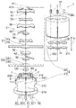
- FIG. 1 is an exploded perspective view of a constant potential electrolytic gas sensor according to a first embodiment of the present invention
- FIG. FIG. 2 is a cross-sectional view of the constant potential electrolytic gas sensor of FIG. 1
- 2 is a perspective view of a case main body of the constant potential electrolysis type gas sensor of FIG. 1.
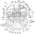
- FIG. FIG. 2 is a top view of a case body of the constant potential electrolytic gas sensor of FIG. 1
- FIG. 5 is a cross-sectional view taken along line VV of FIG. 4
- FIG. 6 is a cross-sectional view corresponding to FIG. 5 of a case body of a modified example
- 6 is a cross-sectional view corresponding to FIG. 5 of a case main body of another modified example
- FIG. 10 is a diagram showing a state in which a reference electrode and a reference electrode lead wire are arranged after the state shown in FIG. 9;
- FIG. 11 is a diagram showing a state in which the reaction electrode lead wire is introduced after the state shown in FIG. 10 , the reaction electrode lead wire is connected to the reaction electrode external electrode, and the holding structure is filled with the protective agent.
- FIG. 12 is a diagram showing a state in which a reaction electrode is arranged after the state shown in FIG. 11;
- FIG. 6 is an exploded perspective view of a constant potential electrolytic gas sensor according to a second embodiment of the present invention;
- FIG. 14 is a top view of a case body of the constant potential electrolytic gas sensor of FIG. 13;
- FIG. 11 is an exploded perspective view of a constant potential electrolytic gas sensor according to a third embodiment of the present invention;
- FIG. 16 is a top view of a case body of the constant potential electrolytic gas sensor of FIG. 15;
- a constant potential electrolysis gas sensor according to several embodiments of the present invention will be described below with reference to the accompanying drawings.
- the embodiments shown below are examples, and the constant potential electrolysis gas sensor of the present invention is not limited to the following examples.
- the term “height direction H” refers to the reaction electrode 31 included in the electrode structure 3, as shown in FIGS. 1 to 3, for example. Or it means the direction perpendicular to the surface of the counter electrode 32 .
- one side in the height direction H in the illustrated example, the external electrodes 51, 52, 53 are The other side in the height direction H (in the illustrated example, the external electrodes 51, 52, 53 connected to the lead wires 41, 42, 43 are connected to the connection points CP).
- the side of the electrodes 51, 52, and 53 (lower side in the figure) is defined as the lower side.
- a direction perpendicular to the height direction H is defined as a horizontal direction.
- a constant potential electrolysis gas sensor 1 (hereinafter referred to as "gas sensor 1") of the first embodiment includes a case 2, an electrode structure 3 housed in the case 2, A lead wire 4 connected to the electrode structure 3 and an external electrode 5 connected to the lead wire 4 are provided.
- the gas sensor 1 further comprises an electrolyte 6 provided in contact with the electrode structure 3 .
- the gas sensor 1 is connected via an external electrode 5 to a controller (not shown) such as a potentiostat.
- the gas sensor 1 applies a constant potential to the electrode structure 3 by the control device, and detects an electric signal generated as a result of an electrochemical reaction occurring in the electrode structure 3 by the control device. to detect.
- Gases to be detected by the gas sensor 1 are not particularly limited, and include oxygen gas, hydrogen sulfide gas, ammonia gas, nitrogen dioxide gas, nitrogen trifluoride gas, chlorine gas, fluorine gas, iodine gas, Chlorine trifluoride gas, ozone gas, hydrogen peroxide gas, hydrogen fluoride gas, hydrogen chloride gas (hydrochloric acid gas), carbon monoxide gas, hydrogen gas, sulfur dioxide gas, silane gas, disilane gas, phosphine gas, germane gas, etc. be done.
- the detection target gas of the gas sensor 1 of the present embodiment is oxygen gas, and an example in which the gas sensor 1 is configured as an oxygen gas sensor will be described below. However, the gas sensor of the present invention can be modified according to the gas to be detected.
- the case 2 is a member that accommodates the electrode structure 3 , the lead wire 4 , the external electrodes 5 extending inside the case 2 , and the electrolytic solution 6 .
- the case 2 includes a case body 21 and a case cover 22, as shown in FIGS.
- a case body 21 is closed with a case cover 22 to form an internal space S in which the above members are accommodated.
- the case body 21 is closed with the case cover 22 to form an electrolytic solution containing space CS for containing the electrolytic solution 6 within the case 2 .
- the internal space S is liquid-tightly sealed so that gas can flow in and out by the air-permeable sheet 31b, OS, and buffer films IB and OB, which will be described later.
- Case main body 21 and case cover 22 are fixed to each other by known adhesive means such as ultrasonic welding or adhesive.
- the case main body 21 and the case cover 22 are not particularly limited, and can be formed, for example, using known resin materials or various resin-like materials by known resin molding or cutting techniques.
- the case body 21 is a member that supports the electrode structure 3, the lead wires 4, the external electrodes 5, and the electrolytic solution 6.
- the structure of the case main body 21 is not particularly limited as long as it can support the above members.
- the case body 21 includes a base portion 211, an electrode structure support portion 212, an intermediate support portion 213, and a plurality of external electrode support portions 214, as shown in FIGS. there is
- the case main body 21 is molded such that the base portion 211, the electrode structure supporting portion 212, the intermediate supporting portion 213, and the external electrode supporting portion 214 are integrated.
- the case body 21 is molded by insert molding so as to be integrated with the external electrodes 5 as well. As a result, the step of attaching the external electrodes 5 to the case body 21 can be omitted.
- the case body 21 may be fixed to each other after each part is separately formed.
- the base portion 211 is a portion that supports the electrode structure support portion 212 , the intermediate support portion 213 and the external electrode support portion 214 .
- the base 211 further supports the electrolytic solution 6 contained in the electrolytic solution containing space CS formed by closing the case body 21 with the case cover 22 .
- the base portion 211 is formed in a flat plate shape (substantially disk shape in the illustrated example), and an intermediate support portion 213 is fixed substantially at the center of the flat plate surface (upper surface). , and a plurality of external electrode support portions 214 are fixed along the periphery of the flat plate surface, spaced apart from each other at approximately equal intervals.
- the base portion 211 is formed with a gas outflow hole h2 continuously provided through the electrode structure support portion 212 and the intermediate support portion 213 . Gas flows out from the internal space S formed inside the case 2 through the gas outflow holes h2 continuously formed in the electrode structure supporting portion 212, the intermediate supporting portion 213 and the base portion 211.
- FIG. 1 A gas outflow hole h2 continuously provided through the electrode structure support portion 212 and the intermediate support portion 213 .
- the electrode structure supporting portion 212 is a portion that supports the electrode structure 3 and the lead wire 4 connected to the electrode structure 3 .
- the electrode structure support portion 212 is supported by the intermediate support portion 213 and the external electrode support portion 214 with respect to the base portion 211 .
- the electrode structure supporting portion 212 is formed in a flat plate shape.
- a plurality of external electrode support portions 214 are fixed to each other at approximately equal intervals.
- Above the approximate center of the flat plate surface of the electrode structure supporter 212 is an electrode structure support space SS for supporting the electrode structure 3 surrounded by a plurality of external electrode supporters 214 (FIGS. 1 and 3). ) are formed.
- a concave portion 212r in which an outflow-side buffer film OB is provided is formed on the surface of the electrode structure supporting portion 212 below the electrode structure supporting space SS.
- a gas outflow hole h2 is formed.
- the outflow-side buffer film OB provided in the concave portion 212r of the electrode structure supporting portion 212 suppresses the outflow of the electrolytic solution 6 through the gas outflow holes h2 together with the outflow-side breathable sheet OS. It has the function of adjusting the pressure. As shown in FIG. 2, the outflow-side buffer film OB is held in the recess 212r by closing the opening of the recess 212r of the electrode structure supporting portion 212 with the outflow-side breathable sheet OS.
- the outflow buffer membrane OB a membrane that suppresses passage of liquid and allows passage of gas can be used.
- a porous membrane made of a fluororesin such as polytetrafluoroethylene (PTFE) is used. .
- the outflow-side air-permeable sheet OS liquid-tightly seals the gas outflow holes h2 of the electrode structure supporting portion 212 together with the outflow-side buffer film OB.
- the outflow-side breathable sheet OS includes a sheet-like (substantially circular sheet-like in the illustrated example) body portion OS1, and a body portion OS1 that protrudes in the out-of-plane direction from the body portion OS1.
- a plurality of (four in the illustrated example) sheet-like (substantially rectangular sheet-like in the illustrated example) extending portions OS2 are arranged at substantially equal intervals in the circumferential direction.
- the body portion OS1 is arranged in the electrode structure support space SS above the electrode structure support portion 212 .
- the extension OS2 extends along the surface of the electrode structure support portion 212 and through the gaps between the adjacent external electrode support portions 214, 214, and as shown in FIG. It is arranged so as to be bent at the outer edge and extend into the electrolytic solution containing space CS.
- the outflow-side air-permeable sheet OS is heat-sealed in a ring shape to the surface of the electrode structure support portion 212 positioned outside the outer periphery of the recess 212r of the electrode structure support portion 212, thereby is fixed to the surface of the electrode structure supporting portion 212 so as to close the recess 212r.
- As the outflow-side air-permeable sheet OS a sheet that suppresses the passage of liquid and allows the passage of gas can be used. be done.
- the intermediate support portion 213 is a portion that supports the electrode structure support portion 212 with respect to the base portion 211 .
- the intermediate support portion 213 is formed in a columnar shape extending in the height direction H from substantially the center of the flat plate surface of the base portion 211, and is fixed to the base portion 211 at the lower end in the height direction H. It is fixed to the electrode structure supporting portion 212 at the upper end in the vertical direction H.
- the intermediate support portion 213 is formed with a gas outflow hole h2 extending continuously through the base portion 211 from the electrode structure support portion 212 via the intermediate support portion 213 .
- the external electrode support part 214 is a part that supports the external electrode 5 and the lead wire 4 connected to the external electrode 5 .
- the external electrode support portion 214 also supports the electrode structure support portion 212 with respect to the base portion 211 .
- the external electrode support portion 214 is formed in a columnar shape extending along the height direction H from the vicinity of the peripheral edge of the flat plate surface of the base portion 211, and is fixed to the base portion 211 at the lower end of the height direction H. It is fixed to the electrode structure supporting portion 212 at an intermediate position in the height direction H.
- the external electrode 5 extending along the height direction H of the external electrode supporting portion 214 and passing through the external electrode supporting portion 214 is fixed to the external electrode supporting portion 214 .
- a plurality of external electrode support portions 214 are provided according to the number of required external electrodes 5 , and the plurality of external electrode support portions 214 are arranged along the periphery of the flat plate surface of the base portion 211 . They are arranged at approximately equal intervals. Note that in the illustrated example, one supporting portion that does not support the external electrode 5 and has substantially the same shape as the external electrode supporting portion 214 is provided. Four support portions including this support portion are arranged along the periphery of the flat plate surface of the base portion 211 at substantially equal intervals.
- the external electrode support part 214 includes a lower external electrode support part 214a positioned below the electrode structure support part 212 in the height direction H, and a lower external electrode support part 214a positioned higher than the electrode structure support part 212. and an upper external electrode support portion 214b located above in the vertical direction H.
- the lower external electrode support portion 214 a supports the external electrode 5 and the electrode structure support portion 212 .
- the upper external electrode support portion 214 b supports the external electrode 5 and positions the connection point CP (for example, the upper end of the external electrode 5 ) with the lead wire 4 of the external electrode 5 at a height corresponding to the electrode structure 3 .
- the upper external electrode support portion 214b includes the guide portion 7 for guiding the lead wire 4 and the connection point CP of the external electrode 5. and a holding structure 8 capable of holding a protective agent that protects the . Details of the guide 7 and the retaining structure 8 will be discussed in greater detail below.
- the upper external electrode support portion 214b is formed in a substantially fan shape with a radially inner portion notched substantially concentrically when viewed in the height direction H.
- the electrode structure supports the electrode structure 3 by being surrounded by the plurality of upper external electrode support portions 214b on the surface of the electrode structure support portion 212 horizontally inward of the upper external electrode support portions 214b.
- a body support space SS is formed in a substantially cylindrical shape. The upper external electrode support portion 214b surrounding the electrode structure support space SS prevents the electrode structure 3 supported in the electrode structure support space SS from deviating to the outside of the electrode structure support space SS in the horizontal direction. do.
- the plurality of upper external electrode support portions 214b are arranged at approximately equal intervals along the periphery of the electrode structure support space SS. Between the adjacent upper external electrode supporting portions 214b, 214b, a gap extending from the approximate center of the flat plate surface of the electrode structure supporting portion 212 to the peripheral edge is formed. This gap is formed by the extending portion OS2 (see FIG. 1) of the outflow-side breathable sheet OS described above and the extending portion 37b (see FIG. (see reference).
- the outflow-side air-permeable sheet OS and the electrolytic solution holding member 37 for supplying electrolytic solution are rotationally moved about the axis extending in the height direction H by arranging the respective extending portions OS2 and 37b in the gap. is regulated.
- the case cover 22 is a member that closes the case body 21 so as to form an internal space S inside the case 2 .
- the case cover 22 is formed in a cylindrical shape with one end (upper end) closed, as shown in FIGS. 1 and 2 .
- the case cover 22 is fixed to the base portion 211 of the case body 21 so as to cover the electrode structure support portion 212, the intermediate support portion 213, and the external electrode support portion 214 of the case body 21 inside the cylinder.
- an internal space S is formed, and at the same time, the electrolyte is accommodated between the inner side surface of the case cover 22, the base portion 211 of the case body 21, and the electrode structure supporting portion 212.
- a space CS is formed.
- a capillary member 22c having a gas inlet hole h1 is attached to one end wall (upper wall) of the case cover 22 with an adhesive or an elastic material (packing, heat, etc.). plastic elastomer, etc.).
- the gas containing the gas to be detected outside the case 2 flows into the reaction electrode 31 inside the case 2 through the gas inflow hole h1.
- the gas inflow hole h1 is configured to limit the amount of the detection target gas flowing into the case 2 to a predetermined amount or less. must be configured.
- the hole diameter of the gas inflow hole h1 is small as possible (for example, 50 ⁇ m ⁇ ).
- the case cover 22 is formed in a cylindrical shape with one end closed by, for example, resin molding as in the present embodiment, such fine gas inlet holes are formed on the one end side wall of the case cover 22 at the same time as the resin molding. difficult to set in By fixing the capillary member 22c pre-drilled with fine gas inlet holes h1 to the molded case cover 22, the fine gas inlet holes h1 can be easily provided in the case cover 22.
- a recess 22r is formed in which the inflow side buffer film IB is provided.
- the inflow-side buffer film IB provided in the concave portion 22r has the function of suppressing the outflow of the electrolytic solution 6 through the gas inflow hole h1 and adjusting the pressure in the case 2 together with the later-described air-permeable sheet 31b. are doing.
- the inflow-side buffer film IB is fixed in the recess 22r of the case cover 2 by a known fixing means such as donut-shaped double-sided tape.
- a membrane that suppresses passage of liquid and allows passage of gas can be used.
- a porous membrane made of a fluorine resin such as polytetrafluoroethylene (PTFE) is used. .
- the electrode structure 3 detects the detection target gas by causing an electrochemical reaction related to the detection target gas in the electrolytic solution 6 .
- the electrode structure 3 is provided on the case body 21, but its arrangement is not particularly limited. In this embodiment, as shown in FIGS. 1 to 4, the electrode structure 3 is arranged in the electrode structure support space SS formed on the electrode structure support 212, and the electrode structure support 212 and the upper wall of the case cover 22 to be supported within the case 2 .
- the electrode structure 3 is formed to have a size corresponding to the electrode structure support space SS. Horizontal outward excursion is restricted. 3 and 4, in order to make it easier to see the arrangement of the electrodes 31, 32, and 33 in the electrode structure 3, illustration of other components included in the electrode structure 3 is omitted.
- the electrode structure 3 corresponds to a reaction electrode 31 that causes an electrochemical reaction related to the detection target gas and an electrochemical reaction related to the detection target gas. and a reference electrode 33 that serves as a reference for the potential of the reaction electrode 31 .
- a reaction electrode 31 , a counter electrode 32 and a reference electrode 33 are arranged so as to be in contact with the electrolytic solution 6 and electrically connected to the external electrode 5 via the lead wire 4 . It should be noted that the electrode structure 3 only needs to be configured to detect the gas to be detected through an electrochemical reaction associated with the gas to be detected. 32 is sufficient.
- the reaction electrode 31 is not particularly limited as long as it can cause an electrochemical reaction related to the gas to be detected in the electrolytic solution 6, and its configuration and arrangement are not particularly limited.
- the reaction electrode 31 has a film-like (substantially circular film-like in the illustrated example) catalyst layer 31a having a surface substantially perpendicular to the height direction H. and a breathable sheet 31b that supports the catalyst layer 31a.
- the reaction electrode 31 is fixed to the case cover 22 via the air-permeable sheet 31b.
- the reaction electrode 31 is incorporated into the electrode structure 3 by closing the case body 21 with the case cover 22 .
- the reaction electrode 31 is formed by forming a catalyst layer 31a on an air-permeable sheet 31b using a known electrode material such as platinum by a known film forming technique such as coating, vapor deposition, or sputtering.
- the catalyst layer 31a of the reaction electrode 31 is formed to have substantially the same shape and surface area (surface area facing the height direction H) as those of the counter electrode 32 and the reference electrode 33 .
- the gas-permeable sheet 31b of the reaction electrode 31 liquid-tightly seals the gas inflow hole h1 together with the inflow-side buffer film IB.
- the air-permeable sheet 31b is heat-sealed to a ring-shaped protrusion 22p provided on the outer periphery of the recess 22r of the case cover 22, so that the case cover 22 closes the recess 22r.
- the air-permeable sheet 31b is configured as a sheet that restricts the passage of liquid and allows the passage of gas, for example, it is configured as a porous sheet made of a fluororesin such as polytetrafluoroethylene (PTFE).
- PTFE polytetrafluoroethylene
- the counter electrode 32 is not particularly limited in its configuration and arrangement as long as it can cause another electrochemical reaction corresponding to the electrochemical reaction related to the gas to be detected.
- the counter electrode 32 is formed in a film shape (a substantially circular film shape in the illustrated example) having a surface substantially perpendicular to the height direction H, and the outflow It is arranged on the main body portion OS1 of the side air-permeable sheet OS.
- a reference electrode 33 and a reaction electrode 31 are stacked in order along the height direction H with a gap from the counter electrode 32 .
- the counter electrode 32 may be arranged side by side at a position where the height in the height direction H is substantially the same as that of the reaction electrode 31 or the reference electrode 33 .
- a counter electrode lead wire 42 to be described later is connected to the surface of the counter electrode 32 .
- the counter electrode 32 is supported on the outflow-side breathable sheet OS by being pressed by the case cover 22 via the components on the counter electrode 32 .
- a film of a known electrode material such as platinum is formed on a breathable sheet (not shown) of the same type as the breathable sheet 31b by a known film forming technique. can be formed by
- the reference electrode 33 is not particularly limited as long as it can serve as a reference for the potential of the reaction electrode 31, and its configuration and arrangement are not particularly limited.
- the reference electrode 33 is formed in a film shape (a substantially circular film shape in the illustrated example) having a surface substantially perpendicular to the height direction H, and the reaction electrode 31 and the counter electrode 32 are stacked along the height direction H with a space between them.
- the reference electrode 33 may be arranged side by side at a position where the height in the height direction H is substantially the same as that of the reaction electrode 31 or the counter electrode 32, for example.
- a reference electrode lead wire 43 to be described later is connected to the surface of the reference electrode 33 .
- the reference electrode 33 is supported between the reaction electrode 31 and the counter electrode 32 by being sandwiched between the upper and lower components in the height direction H of the reference electrode 33 .
- a known electrode material such as platinum is deposited on a breathable sheet (not shown) of the same type as the breathable sheet 31b by a known film formation technique. can be formed by
- a constant voltage is applied to the reaction electrode 31 with reference to the potential of the reference electrode 33 by a control device (not shown) such as a potentiostat connected to the external electrode 5.
- 33 is applied with a constant potential difference.
- the reaction electrode 31 to which a constant potential difference is applied to the reference electrode 33 causes an electrochemical reaction related to the detection target gas when the detection target gas flows onto the reaction electrode 31 .
- an electrochemical reaction related to the detection target gas occurs, another electrochemical reaction also occurs on the counter electrode 32 side corresponding to the electrochemical reaction.
- an electrolytic voltage is generated between the reaction electrode 31 and the counter electrode 32, and an electrolytic current flows. can be detected, and the concentration of the gas to be detected can be obtained according to the magnitude of the electrolysis current.
- the reaction electrode 31, the counter electrode 32 and the reference electrode 33 of the electrode structure 3 need only be arranged so as to contact at least the electrolyte 6, and the contact method with the electrolyte 6 is not particularly limited.
- the electrode structure 3 includes electrolyte holding members 34 , 35 , 36 and 37 capable of holding the electrolyte 6 as shown in FIGS. 1 and 2 .
- the reaction electrode 31, the counter electrode 32 and the reference electrode 33 are in contact with the electrolyte solution 6 held by the electrolyte solution holding members 34, 35, 36 and 37 via the electrolyte solution holding members 34, 35, 36 and 37. placed.
- the reaction electrode 31 , the counter electrode 32 and the reference electrode 33 may be arranged so as to be in direct contact with the electrolytic solution 6 .
- the electrolyte holding members 34 , 35 , 36 , 37 are configured to hold the electrolyte 6 and bring the held electrolyte 6 into contact with the reaction electrode 31 , the counter electrode 32 and the reference electrode 33 .
- the electrolyte solution holding member includes a reaction electrode electrolyte solution holding member 34, a counter electrode electrolyte solution holding member 35, a reference electrode electrolyte solution holding member 36, and an electrolytic solution holding member 36. It includes an electrolyte holding member 37 for liquid supply.
- the respective electrolyte holding members 34, 35, 36, 37 are arranged so as to be in contact with each other, and indirectly connect the reaction electrode 31, the counter electrode 32, and the reference electrode 33 to each other via the electrolyte 6 they hold. placed.
- Body portions 37a of the reaction electrode electrolyte solution holding member 34, the counter electrode electrolyte solution holding member 35, the reference electrode electrolyte solution holding member 36, and the electrolyte solution holding member 37 for supplying an electrolyte solution, which will be described later, have substantially the same shape and shape. It is sized and has the largest surface area (area of the surface facing the height direction H) among the components of the electrode structure 3 and defines the outer edge of the electrode structure 3 . In FIG.
- the respective electrolyte holding members 34, 35, 36 and 37 are separated from each other.
- the ring-shaped portions of the respective electrolyte holding members 34, 35, 36, 37 extending out of the plane of the respective electrodes 31, 32, 33 are aligned with each other. in contact.
- the reaction electrode electrolyte holding member 34 is in contact with the reaction electrode 31 and brings the retained electrolyte 6 into contact with the reaction electrode 31 .
- the reaction electrode electrolyte holding member 34 is formed in a sheet shape (a substantially circular sheet shape in the illustrated example), and the surface of the reaction electrode 31 is formed between the reaction electrode 31 and the reference electrode 33 in the height direction H. are placed in surface contact with the
- the reaction electrode electrolyte holding member 34 has a larger surface area (surface area facing the height direction H) than the electrodes 31 , 32 , 33 .
- the reaction electrode electrolyte holding member 34 is arranged so as to be in contact with the reference electrode electrolyte holding member 36 in the ring-shaped portions extending out of the planes of the respective electrodes 31 , 32 , 33 .
- the reaction electrode electrolyte solution holding member 34 is supplied with the electrolyte solution 6 from the reference electrode electrolyte solution holding member 36 by coming into contact with the reference electrode electrolyte solution holding member 36 .
- the electrolyte holding member 34 for the reaction electrode has a substantially circular sheet shape.
- the counter electrode electrolyte holding member 35 is in contact with the counter electrode 32 and brings the retained electrolyte 6 into contact with the counter electrode 32 .
- the counter electrode 32 and the electrolyte supply electrolyte holding member 37 are located between the counter electrode 32 and the electrolyte supply electrolyte holding member 37 in the height direction H. It is arranged so as to be in surface contact with the surface of the body portion 37a of the electrolytic solution holding member 37 for the battery.
- the counter electrode electrolyte holding member 35 has a larger surface area (surface area facing the height direction H) than the electrodes 31 , 32 , 33 .
- the electrolytic solution holding member 35 for the counter electrode is supplied with the electrolytic solution 6 from the electrolytic solution holding member 37 for supplying electrolytic solution by coming into contact with the body portion 37a of the electrolytic solution holding member 37 for supplying electrolytic solution.
- the counter electrode electrolyte solution holding member 35 has a substantially circular sheet shape. and a plurality of (for example, four) sheet-like (for example, substantially rectangular sheet-like) extending portions that protrude from the main body in the out-of-plane direction and are arranged at approximately equal intervals in the circumferential direction of the main body. may be provided.
- the reference electrode electrolyte holding member 36 is in contact with the reference electrode 33 and brings the retained electrolyte 6 into contact with the reference electrode 33 .
- the reference electrode electrolyte holding member 36 is formed in a sheet shape (a substantially circular sheet shape in the illustrated example), and the surface of the reference electrode 33 is formed between the reaction electrode 31 and the reference electrode 33 in the height direction H. are placed in surface contact with the
- the reference electrode electrolyte holding member 36 has a larger surface area (surface area facing the height direction H) than the electrodes 31 , 32 , 33 .
- the reference electrode electrolyte solution holding member 36 extends out of the plane of each of the electrodes 31 , 32 , 33 in a ring shape so that the reaction electrode electrolyte solution holding member 34 and the electrolyte supply electrolyte solution holding member 37 are separated from each other. It is arranged so as to be in contact with the body portion 37a.
- the reference electrode electrolyte solution holding member 36 is in contact with the body portion 37a of the reaction electrode electrolyte solution holding member 34 and the electrolyte solution holding member 37 for supplying electrolyte solution.
- Electrolyte solution 6 is supplied from 37a, and electrolyte solution 6 is supplied to electrolyte solution holding member 34 for reaction electrode.
- the reference electrode electrolyte solution holding member 36 has a substantially circular sheet shape in the illustrated example, but may have a sheet shape (for example, a substantially circular sheet shape) similarly to the later-described electrolyte solution supplying electrolyte solution holding member 37 . ), and a plurality of (for example, four) sheet-like (for example, substantially rectangular sheet-like) extending portions that protrude from the main body in the out-of-plane direction and are arranged at approximately equal intervals in the circumferential direction of the main body. and may be provided.
- the electrolytic solution holding member 37 for supplying electrolytic solution is in direct contact with the electrolytic solution 6 in the electrolytic solution containing space CS, and allows the electrolytic solution 6 in the electrolytic solution containing space CS to permeate into the electrolytic solution holding member 37 for supplying electrolytic solution. At the same time, the permeated electrolytic solution 6 is supplied to the other electrolytic solution holding members 34 , 35 and 36 .
- the electrolytic solution holding member 37 for supplying electrolytic solution is composed of a sheet-like (substantially circular sheet-like in the illustrated example) main body portion 37a that constitutes a part of the electrode structure 3, and a main body portion 37a that protrudes in the out-of-plane direction from the main body portion 37a.
- the electrolytic solution holding member 37 for supplying electrolytic solution is formed in substantially the same shape and size as the outflow-side breathable sheet OS, and is arranged on the outflow-side breathable sheet OS with the counter electrode 32 and the counter electrode electrolytic solution holding member 35 interposed therebetween. are placed so as to overlap each other.
- the extending portion 37b of the electrolytic solution holding member 37 for supplying electrolytic solution extends along the surface of the electrode structure supporting portion 212 and extends between the adjacent external electrode supporting portions 214, 214. It extends through the gap, is bent at the outer edge of the electrode structure supporting portion 212, and is arranged to extend into the electrolyte solution accommodating space CS.
- the extending portion 37b extending into the electrolytic solution containing space CS directly contacts the electrolytic solution 6 in the electrolytic solution containing space CS and supplies the electrolytic solution 6 from the extending portion 37b to the main body portion 37a.
- Each of the electrolyte holding members 34, 35, 36, 37 is made of a material having electrical insulation and water absorption properties, and is not particularly limited. Examples thereof include silica fiber, cellulose fiber, glass fiber, and the like. It can be composed of a filter paper or the like formed by
- the electrode structure 3 may comprise support sheets 38, 39, as shown in FIGS.
- the support sheets 38 and 39 are laminated in the electrode structure 3, and connect the reaction electrode lead wire 41, the counter electrode lead wire 42 and the reference electrode lead wire 43 to the reaction electrode 31, the counter electrode 32 and the reference electrode 33, respectively. It is used for pressing to suppress poor contact with each other.
- the support sheets 38 and 39 are each formed in a sheet shape (a substantially circular sheet shape in the illustrated example) having a predetermined rigidity, and the reaction electrode electrolyte solution holding member 34 and the reference electrode electrolyte solution are arranged in the height direction H. It is laminated between the holding member 36 and between the reference electrode 33 and the electrolytic solution holding member 37 for supplying electrolytic solution in the height direction H.
- the support sheets 38 and 39 are formed to have slightly larger surface areas (surface areas facing the height direction H) than the reaction electrode 31, the counter electrode 32 and the reference electrode 33. It is configured to apply a pressing force to the entirety of each plane of 33 .
- the support sheets 38 and 39 have surface areas (in the height direction H By having the area of the surface facing ), it is configured so as not to prevent contact between the respective electrolyte holding members.
- Support sheets 38 and 39 can be made of, for example, polyethylene naphthalate (PEN).
- the electrolytic solution 6 is a solution that has electrical conductivity and causes an electrochemical reaction related to the gas to be detected when it comes into contact with the electrode structure 3 .
- the electrolytic solution 6 is contained in the electrolytic solution containing space CS in the case 2 so as to come into contact with the electrode structure 3 via the electrolytic solution holding members 34, 35, 36, and 37. are housed in
- the electrolytic solution 6 can be appropriately selected depending on the type of gas to be detected and the type of the electrode structure 3 used for detection. , a neutral salt aqueous solution such as lithium bromide or calcium chloride can be used.
- a molten salt that is in a liquid state at room temperature and is mainly composed of nitrogen-containing aromatic cations or aliphatic onium cations and fluorine-containing anions can also be used.
- nitrogen-containing aromatic cation for example, an alkylimidazolium ion or an alkylpyridinium ion is used.
- fluorine-containing anion for example, a borofluoride ion, a phosphorus fluoride ion, or a trifluoromethanesulfonate ion is used.
- the lead wire 4 is a member that electrically connects the electrode structure 3 and the external electrode 5 .
- the reaction electrode lead wire 41, the A lead wire 42 and a reference electrode lead wire 43 are provided as the lead wires 4, as shown in FIGS. 1 and 2, the reaction electrode lead wire 41, the counter electrode lead wire 42, and the reference electrode lead wire 43 are provided.
- the reaction electrode lead wire 41, the counter electrode lead wire 42, and the reference electrode lead wire 43 each extend along the respective surfaces of the reaction electrode 31, the counter electrode 32, and the reference electrode 33 at one end sides thereof. , are electrically connected to the respective surfaces of the counter electrode 32 and the reference electrode 33 .
- the reaction electrode lead wire 41, the counter electrode lead wire 42, and the reference electrode lead wire 43 are connected to the other ends of the external electrode 5, respectively. It is electrically connected to each of the reference external electrodes 53 .
- the lead wires 41, 42, 43 are made of metal such as platinum, gold, tungsten, tantalum, etc., and are formed in a wire shape or a ribbon shape. Although three lead wires 41, 42, and 43 are provided in this embodiment, the gas sensor 1 may be provided with at least two electrodes, that is, the reaction electrode 31 and the counter electrode 32, as described above. Correspondingly, at least two lead wires, that is, the lead wire 41 for the reaction electrode and the lead wire 42 for the counter electrode should be provided.
- the external electrode 5 is connected to the electrode structure 3 inside the case 2 from a control device (not shown) such as a potentiostat outside the case 2 for causing an electrochemical reaction related to the gas to be detected.
- a voltage is applied to transmit an electrical signal produced by an electrochemical reaction associated with the gas to be sensed from the electrode structure 3 to a controller.
- a control device not shown
- a reference electrode external electrode 53 are provided as the external electrode 5, as shown in FIG. and a reference electrode external electrode 53 are provided.
- the external electrodes 51 , 52 , 53 extend from the outside of the case 2 to the inside of the case 2 and are provided on the case main body 21 .
- the external electrodes 51 , 52 , 53 each extend along the height direction H from below the base portion 211 of the case body 21 and protrude above the external electrode support portion 214 .
- 21 is provided in the external electrode support portion 214 .
- Each of the external electrodes 51 , 52 , 53 is electrically connected to the reaction electrode lead wire 41 , the counter electrode lead wire 42 and the reference electrode lead wire 43 at one end side (the portion protruding upward from the external electrode supporting portion 214 ). (see FIG. 3), and the other end side (the portion projecting downward from the base portion 211) is electrically connected to a control device (not shown).
- a control device not shown in this embodiment, as shown in FIG.
- the external electrodes 51 , 52 , 53 are arranged in a horizontal direction substantially perpendicular to a straight line connecting the external electrode 52 for a counter electrode and the external electrode 53 for a reference electrode.
- the external electrode 51 for the reaction electrode is arranged so as to be spaced apart from a substantially intermediate position between the external electrode 52 and the external electrode 53 for the reference electrode.
- each of the external electrodes 51, 52, and 53 is provided to extend along the height direction H in this embodiment, they extend in a direction different from the height direction H, for example, along the horizontal direction. may be provided as follows.
- the external electrodes 51, 52, 53 are arranged such that the connection points CP of the external electrodes 51, 52, 53 to which the lead wires 41, 42, 43 are connected are at a height corresponding to the electrode structure 3. arranged to be located.
- the lead wires 41, 42, 43 are arranged substantially horizontally.
- the lead wires 41, 42, and 43 can be easily routed, and the gas sensor 1 can be easily manufactured.
- the "corresponding height” refers to the reference position of the case body 21 (for example, the surface of the base portion 211 and the electrode structure support portion 212), the comparison object (for example, the electrode structure 3 and the electrode 31). , 32, 33), but may also include a position in the height direction H shifted by the length of the height direction H of the comparison object. good.
- connection point CP of the external electrodes 51 , 52 , 53 is located at a height corresponding to the electrode structure 3
- the connection point CP of at least one of the external electrodes 51 , 52 , 53 is positioned at a height corresponding to the electrode structure 3 . It means that it is positioned at a height corresponding to the range in the height direction H.
- the connection point CP of at least one of the external electrodes 51, 52, 53 may be positioned at a height corresponding to one of the electrodes 31, 32, 33 included in the electrode structure 3.
- the connection points CP of the external electrodes 51, 52, and 53 may be located at heights corresponding to the electrodes 31, 32, and 33 corresponding to the external electrodes 51, 52, and 53, respectively.
- the external electrodes 51, 52, and 53 are arranged so that the heights (positions in the height direction H) of the connection points CP of the external electrodes 51, 52, and 53 substantially match each other, as shown in FIG. are placed in As a result, there is no need to change the arrangement height of the corresponding lead wires 41, 42, 43 or to bend them according to the external electrodes 51, 52, 53, so that the lead wires 41, 42, 43 can be It can be easily wired, and the gas sensor 1 can be easily manufactured.
- the connection points CP of the external electrodes 51, 52, and 53 at substantially the same height are positioned at a height corresponding to the reaction electrode 31 of the electrode structure 3, as shown in FIG. there is
- the heights of the connection points CP of the external electrodes 51 , 52 , 53 may be different from each other as long as at least one of them is positioned at a height corresponding to the electrode structure 3 .
- the external electrodes 51, 52, 53 are each formed in a rod shape from metal such as platinum, gold, tungsten, tantalum. Although three external electrodes 51, 52, and 53 are provided in this embodiment, the gas sensor 1 may be provided with at least two electrodes, that is, the reaction electrode 31 and the counter electrode 32, as described above. Correspondingly, at least two external electrodes, that is, the reaction electrode external electrode 51 and the counter electrode external electrode 52 need only be provided.
- the case body 21 is directed from the outside of the case body 21 to the electrode structure 3 via the connection points CP of the external electrodes 51, 52, and 53.
- a guide portion 7 is provided for guiding the lead wires 41, 42, 43 along the lead-in path.
- the guide part 7 is arranged such that the introduction path is positioned at a height corresponding to the connection point CP of the external electrodes 51, 52, 53 and the electrode structure 3 positioned at corresponding heights.
- the lead wires 41, 42, and 43 guide the positions of the connection points CP and the electrode structure 3 in the description "introduction route toward the electrode structure 3 via the connection points CP of the external electrodes 51, 52, and 53." Not only the positions of the connection points CP and the electrode structures 3 that are already arranged when the lead wires 41, 42, and 43 are guided, but also the virtual positions of the connection points CP and the electrode structures 3 that are arranged after the lead wires 41, 42, and 43 are guided. It is a concept that includes In this embodiment, as described above, the guide portion 7 is provided in the upper external electrode support portion 214b where the connection points CP of the external electrodes 51, 52, 53 are positioned. However, the guide portion 7 only needs to be arranged so as to guide the lead wires 41, 42, 43 along the lead-in path described above, and is provided at a portion of the case body 21 other than the upper external electrode support portion 214b. good too.
- the guide part 7 can guide the lead wires 41, 42, 43 from the outside of the case main body 21 along the introduction path toward the electrode structure 3 via the connection points CP of the external electrodes 51, 52, 53, Its configuration is not particularly limited.
- the guide portion 7 guides the lead wires 41, 42, 43 from the outside of the case body 21 toward the connection points CP of the external electrodes 51, 52, 53. and a second guide portion 72 for guiding the lead wires 41 , 42 , 43 from the connection points CP of the external electrodes 51 , 52 , 53 toward the electrode structure 3 .
- the first and second guide portions 71 and 72 are provided on both sides of the connection point CP of the external electrodes 51, 52 and 53.
- the lead wires 41 , 42 , 43 can be routed more accurately to the connection points CP of the external electrodes 51 , 52 , 53 .
- the first and second guide portions 71 and 72 form an introduction path from the outside of the case body 21 to the electrode structure 3 via the connection points CP of the external electrodes 51, 52, and 53.
- the lead wires 41, 42, 43 are arranged on a substantially straight line along the As a result, when the lead wires 41, 42, 43 are arranged between the connection points CP of the external electrodes 51, 52, 53 and the electrode structure 3, the lead wires 41, 42, 43 are maintained substantially straight.
- the lead wires 41, 42, and 43 can be arranged more easily because they can be arranged in the same state. For example, when the lead wires 41, 42, 43 are introduced from the outside of the case main body 21, the lead wires 41, 42, 43 have a predetermined length, that is, the electrodes 31, 32, 33 of the electrode structure 3 and the outside.
- the electrodes 51, 52, and 53 may be introduced in a state of being cut to a length corresponding to the distance between the connection points CP of the electrodes 51, 52, and 53, or may be introduced in a state longer than the predetermined length, and the external electrode 51 , 52 and 53 may be disconnected after being connected to the connection point CP.
- the lead wires 41, 42 and 43 wound on reels are guided through the first guide portion 71 and the second guide portion 72 in this order so that the tips of the lead wires 41, 42 and 43 are connected to the electrode structure.
- the lead wires 41 , 42 , 42 , 42 , 42 , 42 , 42 , 42 , 42 , 42 , 42 , 42 , 42 , 42 , 42 , 42 , 42 , 42 , 42 , 42 , 42 , 42 , 42 , 42 , 42 , 42 , 42 , 42 , 42 , 42 , 42 , 42 , 42 , 42 , 42 , 42 , 42 43 is fixed, and the lead wires 41, 42, 43 are joined to the external electrodes 51, 52, 53 by welding or the like at the connection points CP, and then connected to the outside of the first guide portion 71 or the first guide portion 71.
- the lead wires 41, 42, 43 can be arranged at predetermined positions by cutting between the connection points CP. By doing so, it is possible to automate the routing of the lead wires 41 , 42 , 43 while suppressing positional displacement of the lead wires 41 , 42 , 43 .
- the first guide portion 71 is positioned at a height corresponding to the connection point CP of the external electrodes 51, 52, 53, as shown in FIG. More specifically, the later-described bottom surface of the first guide portion 71 is positioned at a height corresponding to the connection points CP of the external electrodes 51 , 52 , 53 .
- the lead wires 41, 42 and 43 are introduced from the outside of the case main body 21 toward the connection points CP of the external electrodes 51, 52 and 53, the lead wires 41, 42 and 43 are moved substantially horizontally. By introducing them, the lead wires 41 , 42 , 43 can be positioned at the connection points CP of the external electrodes 51 , 52 , 53 .
- the heights (positions in the height direction H) of the connection points CP of the external electrodes 51, 52, and 53 are substantially the same.
- the first guides 71 for 43 are positioned at substantially the same height as each other.
- the respective The first guide portions 71 may be positioned at heights corresponding to the connection points CP of the external electrodes 51 , 52 and 53 , respectively, and the connection points of the external electrodes 51 , 52 and 53 may be positioned from the outside of the case body 21 . It may be slanted with respect to the horizontal towards the CP.
- the second guide part 72 is positioned at a height corresponding to the connection points CP of the external electrodes 51, 52, 53 and the electrode structure 3, as shown in FIG. More specifically, the later-described bottom surface of the second guide portion 72 is positioned at a height corresponding to the connection points CP of the external electrodes 51 , 52 , 53 and the electrode structure 3 .
- the lead wires 41, 42, 43 are introduced from the connection points CP of the external electrodes 51, 52, 53 toward the electrode structure 3, the lead wires 41, 42, 43 are introduced along the substantially horizontal direction. By doing so, the lead wires 41 , 42 , 43 can be positioned on the electrode structure 3 .
- the electrodes 31, 32, and 33 of the electrode structure 3 are stacked along the height direction H, so that they are positioned at different heights within the electrode structure 3.
- the second guide portions 72 for the electrodes 31, 32, 33 all correspond to the reaction electrode 31 located at the highest position among the electrodes 31, 32, 33. It is positioned at a height where As a result, the lead wires 41, 42 and 43 can be similarly introduced along the substantially horizontal direction when the lead wires 41, 42 and 43 are wired for any of the electrodes 31, 32 and 33. can.
- FIG. 5 shows that the lead wires 41, 42 and 43 of the electrode structure 3 are stacked along the height direction H, so that they are positioned at different heights within the electrode structure 3.
- the second guide portions 72 for the electrodes 31, 32, 33 all correspond to the reaction electrode 31 located at the highest position among the electrodes 31, 32, 33. It is positioned at a height where
- the lead wires 41, 42 and 43 can be similarly introduced along the substantially horizontal direction when the lead wires 41, 42 and 43 are wired
- the second guide portion 72 has a height corresponding to each of the electrodes 31, 32, and 33 according to the position of each of the electrodes 31, 32, and 33 in the height direction H. may be located at More specifically, the bottom surface of the second guide portion 72 has a height corresponding to the surface of each of the electrodes 31, 32, and 33 according to the position of each of the electrodes 31, 32, and 33 in the height direction H. may be located in As a result, the degree of bending of the lead wires 41, 42, 43 caused by the difference in height between the connection points CP of the external electrodes 51, 52, 53 and the electrodes 31, 32, 33 is moderated. Therefore, the load applied to the lead wires 41, 42, 43 can be reduced.
- the second guide portion 72 is provided between the connection point CP of each of the external electrodes 51, 52, 53 and each of the electrodes 31, 32, 33, as shown in FIG. You may incline corresponding to the difference in height. More specifically, the bottom surface of the second guide portion 72 is shaped so as to correspond to the difference in height between the connection points CP of the external electrodes 51, 52, and 53 and the electrodes 31, 32, and 33, respectively. It can be tilted.
- the case body 21 has a wall W formed around the connection points CP of the external electrodes 51, 52, and 53 in the horizontal direction, as shown in FIGS.
- the first guide portion 71 is formed by the peripheral wall of the first recess WR1 provided in the wall portion W on the side opposite to the electrode structure 3 in the introduction path of the lead wires 41, 42, 43.
- the portion 72 is constituted by the peripheral wall of the second recess WR2 provided in the wall portion W on the side of the electrode structure 3 in the introduction path of the lead wires 41 , 42 , 43 .
- the first and second recesses WR1 and WR2 pass through the wall W along the introduction paths of the lead wires 41, 42 and 43, respectively.
- the bottom and side surfaces defining the first and second recesses WR1 and WR2 respectively form the peripheral walls of the first and second recesses WR1 and WR2 and function as guide surfaces against which the lead wires 41, 42 and 43 abut. do.
- the bottom and side surfaces defining the first and second recesses WR1 and WR2 are formed substantially parallel to the direction in which the lead wires 41, 42 and 43 extend.
- each of the first and second recesses WR1 and WR2 the distance between the side surfaces on both sides facing the first and second recesses WR1 and WR2 is at least larger than the outer diameters of the lead wires 41, 42 and 43.
- the shape is not particularly limited as long as it is formed to be large.
- each of the first and second recesses WR1 and WR2 has a constant interval between the side surfaces on both sides below in the height direction H, and an opening at the upper end above the height direction H. It is formed in a substantially funnel shape so as to become larger toward it.
- the lead wires 41, 42 and 43 can be easily inserted into the first and second guide portions 71 and 72 from the upper side of the case body 21 in the height direction H, and the electrode structure 3 and the external electrodes 51 can be easily inserted. , 52, 53 and the lead wires 41, 42, 43 are easily arranged.
- the case main body 21 is placed on each of the external electrodes 51, 52, 53 so as to cover the connection points CP of the external electrodes 51, 52, 53.
- It has a holding structure 8 capable of holding a fixed amount of protective agent PA (see FIGS. 11 and 12).
- the connection point CP can be protected by the protective agent PA, and corrosion of the connection point CP by the electrolytic solution 6 can be suppressed.
- the holding structure 8 can hold a predetermined amount of the protective agent PA, it facilitates control of the amount of the protective agent PA to be applied to the connection point CP and promotes automation of manufacturing the gas sensor 1 .
- the holding structure 8 is provided corresponding to the connection points CP of the external electrodes 51, 52, 53 positioned at a height corresponding to the electrode structure 3, so that the holding structure 8 can be connected to the electrodes It is positioned at a height corresponding to the connection point CP between the structure 3 and the external electrodes 51, 52, 53, or at a height above and below it. Therefore, after arranging the electrodes 31, 32, 33 of the electrode structure 3 and arranging the lead wires 41, 42, 43 between the electrodes 31, 32, 33 and the connection points CP of the external electrodes 51, 52, 53, , the connection points CP of the external electrodes 51 , 52 , 53 can be coated with the protective agent PA.
- the applicator for applying the protective agent PA is placed on the case main body 21 below the position where the electrode structure 3 is provided.
- the protective agent PA can be easily applied because the holding structure 8 can be easily accessed without needing to be inserted deep into the holding structure 8 .
- the holding structure 8 is not particularly limited as long as it can hold a predetermined amount of protective agent PA so as to cover the connection points CP of the external electrodes 51, 52, 53.
- the holding structure 8 has a wall W formed around the connection points CP of the external electrodes 51, 52, 53 in the horizontal direction.
- the wall portion W is provided along the entire circumference of the connection point CP in the horizontal direction, and extends above the connection point CP in the height direction H.
- the holding structure 8 can hold a predetermined amount of the protective agent PA by the wall W formed around the connection point CP in the horizontal direction, and protect the connection point CP with the predetermined amount of the protective agent PA. can be done.
- the holding structure 8 includes a wall W formed around the connection point CP and a bottom B closing the space surrounded by the wall W with the lower end of the wall W. It is formed in a cylindrical shape. External electrodes 51, 52 and 53 protrude from the surface of the bottom portion B forming the holding structure 8, and the upper ends of the protruding external electrodes 51, 52 and 53 are connected to lead wires 41, 42 and 43, respectively. A connection point CP is formed.
- the holding structure 8 has an introduction path extending from the outside of the case body 21 toward the electrode structure 3 via the connection points CP of the external electrodes 51, 52, and 53.
- a guide portion 7 for guiding the lead wires 41, 42, 43 along is provided. By providing the guide portion 7 in the holding structure portion 8, the lead wires 41, 42, and 43 are guided from the outside of the case body 21 to the electrode structure 3, and the electrode structure 3 and the external electrodes 51, 52, and 53 are connected.
- Arrangement of the lead wires 41, 42, 43 between the points CP, connection of the lead wires 41, 42, 43 to the connection points CP of the external electrodes 51, 52, 53, and a protective agent to the holding structure 8 PA filling can be performed at approximately the same location without requiring repositioning of the leads 41,42,43.
- the protective agent PA covers the connection points CP of the external electrodes 51, 52, and 53, thereby suppressing contact of the connection points CP with the electrolyte solution 6 and suppressing corrosion of the connection points CP by the electrolyte solution 6. .
- the protective agent PA is not particularly limited as long as it can protect the connection points CP of the external electrodes 51 , 52 , 53 from the electrolytic solution 6 , but from the viewpoint of easiness of filling the holding structure 8 . It is preferable that the thermosetting resin is in an uncured state before filling and can be cured after filling. It is more preferable to use a thermosetting resin having a
- FIG. 8 to 12 a method of manufacturing the gas sensor 1 of the present embodiment will be described with reference to the entire accompanying drawings, especially FIGS. 8 to 12.
- FIG. 8 to 12 the following description is only an example, and the gas sensor and the method for manufacturing the gas sensor of the present invention are not limited to the following example. Also, although some steps are described in order below, these steps may be performed simultaneously or in a different order. 8 to 12, other components of the electrode structure 3 are omitted in order to make the arrangement of the electrodes 31, 32, 33 of the electrode structure 3 easier to understand.
- the manufacturing method of the gas sensor 1 of this embodiment includes a step of providing a case body 21, as shown in FIG. External electrodes 51 , 52 , 53 are fixed to the case body 21 .
- the case main body 21 and the external electrodes 51, 52, 53 are integrally molded, so the step of assembling the separately formed case main body 21 and the external electrodes 51, 52, 53 can be omitted.
- the outflow-side buffer film OB and the outflow-side breathable sheet OS are laminated on the case body 21, and the outflow-side breathable sheet OS is fixed to the case body 21 by heat-sealing. be.
- the manufacturing method includes, as the next step, the step of providing the electrode structure 3 on the case body 21, as shown in FIG.
- the counter electrode 32 of the electrode structure 3 is provided on the case body 21 .
- the counter electrode 32 is laminated on the surface of the outflow-side breathable sheet OS in this embodiment.
- the reference electrode 33 and the reaction electrode 31 of the electrode structure 3 are laminated above the counter electrode 32 in parallel with the subsequent steps or after the subsequent steps.
- each electrode 31, 32, 33 may be laminated in a different order.
- the step of introducing 41, 42, 43 is included.
- the counter electrode lead wire 42 is introduced from the outside of the case body 21 toward the electrode structure 3 via the connection point CP of the counter electrode external electrode 52 .
- the introduction of the counter electrode lead wire 42 from the outside of the case body 21 and the subsequent electrode lead wire 42 are introduced.
- the arrangement of the counter electrode lead wire 42 between the structure 3 and the connection point CP can be performed in a series of steps.
- connection point CP is positioned at a height corresponding to the electrode structure 3
- the lead wire 42 for the counter electrode can be introduced along the substantially horizontal direction, and the introduction of the lead wire 42 for the counter electrode can be performed by mechanical operation. can be easily done with Further, in this embodiment, since the guide portion 7 for guiding the counter electrode lead wire 42 is provided, the counter electrode lead wire 42 can be laid easily and accurately.
- the lead wire 42 for the counter electrode is introduced from the upper side of the case body 21 to the connection point CP and the electrode structure 3 . may be introduced towards both
- lead wires 41, 42 and 43 are arranged between the surfaces of the electrodes 31, 32 and 33 and the connection points CP of the external electrodes 51, 52 and 53.
- the counter electrode lead wire 42 is arranged between the surface of the counter electrode 32 and the connection point CP of the counter electrode external electrode 52 .
- the counter electrode lead wire 42 may be positioned at least above the surface of the counter electrode 32 in the height direction H, and may be in contact with the surface of the counter electrode 32 as shown in FIG. Alternatively, it may be slightly floating from the surface of the counter electrode 32 .
- This step is performed before the counter electrode lead wire 42 is connected to the counter electrode 32 and the counter electrode external electrode 52 in this embodiment.
- a step of connecting the lead wires 41, 42, 43 to the external electrodes 51, 52, 53 at the CP is included.
- lead wires having a length equal to or longer than a predetermined length such as lead wires wound on reels are used as the lead wires 41, 42 and 43
- the lead wires 41, 42 and 43 are connected to the external electrode 51, 52, 53
- the lead wires 41, 42, 43 are connected to the external electrodes 51, 52, 53
- the lead wires 41, 42, 43 are arranged on the surfaces of the electrodes 31, 32, 33.
- a step of cutting the lead wires 41, 42, 43 at a predetermined position may be included.
- the counter electrode lead wire 42 is arranged on the surface of the counter electrode 32 and connected to the counter electrode external electrode 52 at the connection point CP of the counter electrode external electrode 52 .
- the connection between the counter electrode lead wire 42 and the counter electrode external electrode 52 is performed by welding or the like. In the prior art, after connecting one end of the lead wire to the external electrode, it is necessary to bend and wire the lead wire so that the other end of the lead wire is placed on the electrode. It was difficult.
- the counter electrode lead wire 42 is connected to the counter electrode external electrode 52 while being arranged on the surface of the counter electrode 32, such complicated wiring is not necessary.
- the counter electrode lead wire 42 only needs to be positioned at least above the surface of the counter electrode 32 in the height direction H, and even if it is in contact with the surface of the counter electrode 32 as shown in FIG. Alternatively, it may be slightly floating from the surface of the counter electrode 32 .
- the counter electrode lead wire 42 is formed by stacking other components above the counter electrode 32 in a subsequent step, and closing the case body 21 with the case cover 22 (see FIGS. 1 and 2). By being pressed onto the surface of the counter electrode 32 , it is connected so as to extend along the surface of the counter electrode 32 .
- the reference electrode 33 is stacked as shown at 10 .
- the reference electrode lead wire 43 is connected to the electrode structure from the outside of the case body 21 via the connection point CP (see FIGS. 3 and 4) of the reference electrode external electrode 53 in the same manner as the counter electrode lead wire 42. Introduced along an introductory path towards the body 3 .
- the reference electrode lead wire 43 is arranged between the surface of the reference electrode 33 and the connection point CP of the reference electrode external electrode 53, the reference electrode lead wire 43 is arranged on the surface of the reference electrode 33 and connected to the reference electrode external electrode. It is connected to the reference external electrode 53 at the connection point CP of the electrode 53 .
- the method of connecting the reference electrode lead wire 43 to the reference electrode external electrode 53 and the reference electrode 33 is performed in the same manner as the counter electrode lead wire 42 .
- the reaction electrode lead wire 41 is connected to the reaction electrode external electrode 51 from the outside of the case main body 21 in the same manner as the counter electrode lead wire 42 and the reference electrode lead wire 43. It is introduced along the introduction path toward the electrode structure 3 via the point CP.
- the reaction electrode lead wire 41 is arranged between the virtual surface of the reaction electrode 31 (see FIG. 12) arranged thereafter and the connection point CP of the reaction electrode external electrode 51, and then the reaction electrode lead wire 41 arranged thereafter.
- reaction electrode lead wire 41 is arranged on the virtual surface of the reaction electrode 31 which is arranged after the reaction electrode lead wire 41 is arranged. It may be arranged on the surface of the actually arranged reaction electrode 31 .
- the connection of the reaction electrode lead wire 41 to the reaction electrode external electrode 51 is performed in the same manner as the connection of the counter electrode lead wire 42 and the reference electrode lead wire 43 .
- a predetermined amount of protective agent PA is supplied to the holding structure 8 so as to cover the connection points CP of the external electrodes 51, 52, and 53 with the protective agent PA.
- a step may be included.
- the connection points CP of the external electrodes 51 , 52 , 53 are covered with the protective agent PA to suppress corrosion by the electrolytic solution 6 . Since the holding structure 8 is configured to hold a predetermined amount of the protective agent PA, it becomes easy to manage the amount of the protective agent PA when supplying the protective agent PA.
- the reaction electrode 31 is stacked on the reaction electrode electrolyte holding member 34 (see FIGS. 1 and 2) and the reaction electrode lead wire 41 to form a reaction electrode.
- a lead wire 41 is connected so as to extend along the surface of the reaction electrode 31 .
- the reaction electrode 31 is fixed to the case cover 22 via the breathable sheet 31b by fixing the breathable sheet 31b to the case cover 22 . Therefore, by closing the case body 21 with the case cover 22 , the reaction electrode 31 is stacked on the reaction electrode electrolyte holding member 34 and the reaction electrode lead wire 41 .
- the case cover 22 is fixed to the case body 21 by known adhesive means such as ultrasonic welding or adhesive.
- the electrolytic solution 6 (see FIG. 2) is supplied to the electrolytic solution containing space CS in the case 2 formed by fixing the case cover 22 to the case main body 21 .
- the electrodes of the electrode structure 3 mainly include at least two reaction electrodes for detecting different detection target gases, and accordingly the lead wire 4 and the external electrode 5 are Each of them differs from the gas sensor 1 of the first embodiment in that it includes at least two reaction electrode lead wires and at least two reaction electrode external electrodes.
- the description of the matters common to the gas sensor 1 of the first embodiment described above will be omitted, and the description will focus on the points of difference.
- the electrodes of the electrode structure 3 are composed of two reaction electrodes 31 and 311 for detecting different target gases and one counter electrode 32. , and one reference pole 33 .
- one counter electrode 32 and one reference electrode 33 are commonly used for the two reaction electrodes 31,311.
- the electrodes of the electrode structure 3 may include two counter electrodes corresponding to the two reaction electrodes 31 and 311 respectively.
- the two counter electrodes 32 are formed, for example, by depositing two electrode materials (e.g., substantially semicircular) on one air-permeable sheet (e.g., substantially circular) with a slit-shaped space between each other.
- the sensor 1 can also be formed using the case 2 of.
- the gas sensor 1 detects a first detection target gas such as oxygen gas with one of the two reaction electrodes 31 and 311 (hereinafter also referred to as "first reaction electrode 31"), A second detection target gas such as hydrogen sulfide gas or carbon monoxide gas is detected by the other one of the two reaction electrodes 31 and 311 (hereinafter also referred to as "second reaction electrode 311"). can do.
- the electrode structure 3 includes two reaction electrodes 31 and 311, but it is sufficient to include at least two reaction electrodes for the purpose of detecting different detection target gases. It may contain three reactive electrodes like the gas sensor 1 of the third embodiment described below, or may contain more than three reactive electrodes. When the electrode structure 3 includes at least two reactive electrodes, it may include at least two counter electrodes corresponding to each of the at least two reactive electrodes.
- the first reaction pole 31 and the second reaction pole 311 are arranged so as not to overlap each other when viewed in the height direction H, as shown in FIG. More specifically, the first reaction electrode 31 is stacked with the counter electrode 32 and the reference electrode 33 in the height direction H, and the second reaction electrode 311 is stacked with the first reaction electrode 31, the counter electrode 32 and the reference electrode 33. , in a direction perpendicular to the height direction H (horizontal direction). Thereby, gas can be independently supplied to each of the reaction electrodes 31 and 311 from the outside. When the electrode structure includes three or more reaction electrodes, the three or more reaction electrodes are separated from each other in a direction (horizontal direction) perpendicular to the height direction H. placed.
- the positions of the two reaction electrodes 31 and 311 in the height direction H with respect to each other are not particularly limited, but in this embodiment, the first and second reaction electrodes 31 and 311 are located on the upper wall of the case cover 22. , the second reaction pole 311 is arranged at a height corresponding to the first reaction pole 31 .
- the electrode structure includes three or more reaction electrodes, the three or more reaction electrodes are arranged at heights corresponding to each other.
- the first reaction electrode 31 and the second reaction electrode 311 have the same configuration as the reaction electrode 31 described with respect to the gas sensor 1 of the first embodiment, and have the same configuration as each other. It may have a configuration different from that of the reaction electrode 31 in one embodiment, or may have a configuration different from each other.
- the reaction electrode electrolyte solution holding member 34 laminated on the two reaction electrodes 31 and 311 is, as shown in FIG. It is shaped and sized to contact both surfaces of 311 . Thereby, the electrolyte solution 6 can be supplied to both of the two reaction electrodes 31 and 311 from one reaction electrode electrolyte holding member 34 .
- the reaction electrode electrolyte holding member 34 has a shape and size suitable for a first electrode structure supporting space SS and a second electrode structure supporting space SS1 of the case body 21, which will be described later, and is a sheet.
- the reference electrode electrolyte solution holding member 36 is also formed in a sheet shape with substantially the same shape and size as the reaction electrode electrolyte solution holding member 34 .
- the counter electrode electrolyte solution holding member 35 is formed in a substantially circular sheet shape that fits in the first electrode structure supporting space SS, but has substantially the same shape as the reaction electrode electrolyte solution holding member 34. and size, and may be formed into sheets.
- the supporting sheets 38 and 39 which are optionally laminated in the electrode structure 3, have substantially the same shape as the reaction electrode electrolyte solution holding member 34 and the reference electrode electrolyte solution holding member 36, but have the same shape as the electrolyte solution holding member 36. It is formed in a size smaller than that of the reaction electrode electrolyte solution holding member 34 and the reference electrode electrolyte solution holding member 36 so as not to interfere with the contact between the holding members.
- the electrolytic solution holding members 37 for supplying electrolytic solution stacked in the electrode structure 3 are composed of a sheet-like main body portion 37a and a sheet-like main body portion 37a, which extends in the out-of-plane direction from the main body portion 37a and in the opposite directions to each other. It has two sheet-like extensions 37b, 37b that protrude on the same straight line.
- the main body portion 37a is adapted to a first electrode structure supporting space SS on the electrode structure supporting portion 212, which will be described later, and also to a main body groove portion 2121a (see FIG. 14) of the electrode structure supporting portion 212, to be described later.
- the main body portion 37a is laminated with the first reaction electrode 31, the counter electrode 32 and the reference electrode 33 (and the electrolyte holding member for each electrode) in the first electrode structure supporting space SS.
- Each of the two extensions 37b, 37b is formed to fit an extension groove 2121b (see FIG. 14) of the electrode structure supporter 212, which will be described later.
- the two extending portions 37b, 37b extend in mutually opposite directions with respect to the electrode structure supporting portion 212 of the case body 21, are bent at the outer edge of the electrode structure supporting portion 212, and face each other in the electrolytic solution containing space CS. (see also FIG. 2).
- a portion of one of the two extensions 37b, 37b extends to the second reaction electrode 311 (and the reaction electrode electrolyte holding member 34 and It is partially laminated with the reference electrode electrolyte holding member 36).
- the gas sensor 1 of the present embodiment has two reaction electrodes 31 and 311 connected to the two reaction electrodes 31 and 311, respectively, corresponding to the two reaction electrodes 31 and 311. It has electrode lead wires 41 and 411 and two reaction electrode external electrodes 51 and 511 connected to the two reaction electrode lead wires 41 and 411 respectively. That is, in the gas sensor 1 of the present embodiment, the lead wire 4 includes two reaction electrode lead wires 41 and 411, a counter electrode lead wire 42 connected to the counter electrode 32, and a reference electrode lead wire 42 connected to the reference electrode 33. and leads 43 .
- the external electrode 5 includes two reaction electrode external electrodes 51 and 511, a counter electrode external electrode 52 connected to the counter electrode lead wire 42, and a reference electrode external electrode connected to the reference electrode lead wire 43. 53.
- the two reaction electrode external electrodes 51 and 511 are arranged such that the connection points CP and CP of the two reaction electrode external electrodes 51 and 511 are positioned at heights corresponding to the two reaction electrodes 31 and 311. .
- the two reaction electrode lead wires 41 and 411 can be routed along a substantially horizontal direction, and there is no need to bend them greatly.
- the two reaction electrode lead wires 41 and 411 can be easily routed, and the gas sensor 1 can be easily manufactured. can.
- the electrode structure includes three or more reaction electrodes, three or more reaction electrode lead wires and three or more reaction electrode external electrodes corresponding to each of the three or more reaction electrodes is provided.
- the three or more reaction electrode external electrodes are arranged such that the connection points of the three or more reaction electrode external electrodes are located at a height corresponding to the three or more reaction electrodes.
- the reaction electrode external electrode may be arranged such that the connecting portion of the reaction electrode external electrode is positioned at a height different from that of the reaction electrode.
- the case 2 additionally includes a second reaction electrode 311, a second reaction electrode lead wire 411, and a second reaction electrode external electrode 511 in addition to the gas sensor 1 of the first embodiment. is different from the case 2 of the gas sensor 1 of the first embodiment.
- the case body 21 of the case 2 in this embodiment has one external electrode (in this embodiment, the first reaction electrode external electrode 51 and the reference electrode external electrode). 53), and two external electrodes (in this embodiment, the second reaction electrode external electrode 511 and the counter electrode external electrode 52). and one external electrode support portion 214 .
- Each of the external electrode support parts 214, 214 for supporting one external electrode 51, 53 is provided with one guide part 7 and one holding structure part 8, and for supporting two external electrodes 511, 52
- the external electrode support 214 is provided with two guides 7,7 and two holding structures 8,8.
- a partition wall W1 is provided between the two holding structures 8, 8, whereby the amount of the protective agent PA used for the connection points CP of the external electrodes 511, 52 is controlled by a predetermined amount. is restricted to be Regardless of the illustrated example, the guide portion 7 may have the same structure as the guide portion 7 of the gas sensor 1 of the first embodiment.
- the number, shape, arrangement, etc. of the external electrode supporting parts, guide parts, and holding structure parts can be appropriately modified according to the number, shape, arrangement, etc. of the reaction electrode, counter electrode, reference electrode, and external electrode.
- the case body 21 has three external electrodes on the surface of the electrode structure supporting portion 212 near the center of the electrode structure supporting portion 212 in the horizontal direction.
- a first electrode structure support space SS surrounded by a support portion 214 and a second electrode between two external electrode support portions 214, 214 adjacent along the periphery of the first electrode structure support space SS.
- a structure support space SS1 is formed.
- the first electrode structure support space SS In the first electrode structure support space SS, the first reaction electrode 31, the counter electrode 32 and the reference electrode 33 (and the electrolyte holding members for each electrode) are supported, and in the second electrode structure support space SS1 , the second reaction electrode 311 (as well as the reaction electrode electrolyte solution holding member 34 and the reference electrode electrolyte solution holding member 36) are supported.
- the first electrode structure support space SS is formed in the same shape and size as the electrode structure support space SS described with respect to the gas sensor 1 of the first embodiment. It may be formed in a different shape and size from the electrode structure support space SS in the form.
- the electrode structure supporting portion 212 of the case body 21 is formed with a groove portion 2121 in which the outflow-side air-permeable sheet OS and the electrolytic solution holding member 37 for supplying electrolytic solution are arranged.
- the groove portion 2121 is formed to have a shape and size that allow insertion of the outflow-side breathable sheet OS and the electrolytic solution holding member 37 for supplying electrolytic solution.
- the groove portion 2121 includes a main body groove portion 2121a into which the main body portion OS1 of the outflow-side breathable sheet OS and the main body portion 37a of the electrolytic solution holding member 37 for supplying electrolytic solution can be inserted, an extension portion OS2 of the outflow-side breathable sheet OS, and an electrolytic solution.
- the body groove portion 2121a is provided below the first electrode structure support space SS, and one of the two extension groove portions 2121b, 2121b is provided below a portion of the second electrode structure support space SS1. It is The second reaction electrode 311 supported in the second electrode structure support space SS1 is arranged so as to straddle the edge of the extending groove 2121b in the direction perpendicular to the extending direction of the extending groove 2121b.
- the outflow-side air-permeable sheet OS arranged in the grooves 2121 of the electrode structure supporting portion 212 includes a sheet-like body portion OS1 and two sheets in opposite directions to each other in the out-of-plane direction from the body portion OS1. It has two sheet-like extensions OS2, OS2 that protrude substantially on the same straight line.
- the two extending portions OS2, OS2 extend along the extending groove portion 2121b of the groove portion 2121 in directions opposite to each other with respect to the electrode structure supporting portion 212 of the case body 21, and are bent at the outer edge of the electrode structure supporting portion 212. and arranged at opposite positions in the electrolyte containing space CS (see also FIG. 2).
- the extension OS2 in the electrolyte storage space CS is entirely exposed to the electrolyte 6. It becomes difficult for the gas in the electrolytic solution containing space CS to be immersed and discharged to the outside of the case 2 through one of the extensions OS2. However, even if this happens, the other extension OS2 of the two extensions OS2, OS2 is at least partially ) Since it is not immersed in the electrolytic solution 6, the gas in the electrolytic solution containing space CS can be discharged to the outside of the case 2 through the other extending portion OS2.
- the outflow-side breathable sheet OS having the two extending portions OS2, OS2 extending in substantially the same straight line in opposite directions even if the gas sensor 1 is tilted, it is possible to store the electrolytic solution. Since the gas in the space CS can be discharged to the outside of the case 2, the pressure in the electrolyte containing space CS can be kept constant.
- two outflow-side breathable sheets OS having two extending portions OS2, OS2 extending in substantially the same straight line in opposite directions to each other can be provided. Reaction electrode external electrodes 51 and 511, a counter electrode external electrode 52, and a reference electrode external electrode 53 are arranged.
- the second reaction electrode 311 is arranged in the second electrode structure support space SS1 above the electrode structure support portion 212 of the case body 21 in the direction perpendicular to the extending direction of the extending groove portion 2121b. It is arranged so as to straddle the edge of the extending groove portion 2121b (see FIG. 14). Therefore, a part of the second reaction electrode 311 is provided on the case main body 21 via (the extension part 37b of) the electrolyte solution holding member 37 for electrolyte supply, and the other part of the second reaction electrode 311 is provided. The portion is provided on the case main body 21 without interposing (extending portion 37b of) the electrolyte holding member 37 for electrolyte supply.
- the second reaction electrode 311 is more reliably supplied with the electrolytic solution 6 from the electrolytic solution holding member 37 for electrolytic solution supply, and is hard case without the electrolytic solution holding member 37 for electrolytic solution supply.
- the contact with the second reaction electrode lead wire 411 is ensured more reliably.
- the second reaction electrode lead wire 411 is arranged on the case main body 21 without passing through (the extending portion 37b of) the electrolytic solution holding member 37 for supplying electrolytic solution. It is preferably arranged so as to be connected to another part of the provided second reaction electrode 311 .
- the case cover 22 of the case 2 is provided with two capillary members 22c, 22c corresponding to the positions where the two reaction electrodes 31, 311 are provided. Gas flows into the case 2 from the gas inlet holes h1 provided in the two capillary members 22c, 22c respectively, and the gas flows into the two reaction electrodes 31, 311 provided corresponding to the respective capillary members 22c. supplied.
- the capillary member 22c for each of the reaction electrodes 31 and 3111, the size of the gas inlet hole h1 can be changed according to the type of detection target gas to be detected, for example, in order to obtain suitable gas output characteristics. can be done.
- the case cover 22 is provided with holes for allowing gas to flow into the case 2 corresponding to the reaction electrodes 31 and 311 respectively.
- One may be provided corresponding to one or one, or may not necessarily be provided.
- the gas sensor 1 of the second embodiment can be manufactured by a method similar to the method of manufacturing the gas sensor 1 described for the gas sensor 1 of the first embodiment.
- the electrodes of the electrode structure 3 are composed of three reaction electrodes 31, 311, 312 for detecting different detection target gases, and one It includes a counter electrode 32 and one reference electrode 33 .
- one counter electrode 32 and one reference electrode 33 are commonly used for the three reaction electrodes 31 , 311 , 312 .
- the electrodes of the electrode structure 3 may include three counter electrodes corresponding to the three reaction electrodes 31, 311 and 312 respectively. In that case, the three counter electrodes can be formed, for example, by depositing three electrode materials spaced apart from each other on one breathable sheet, or separately and separately from each other.
- the gas sensor 1 detects a first detection target gas such as oxygen gas by the first reaction electrode 31 out of the three reaction electrodes 31 , 311 , 312 .
- a second detection target gas such as hydrogen sulfide gas is detected by the second reaction electrode 311, and the third reaction electrode 312 of the three reaction electrodes 31, 311, 312 detects, for example, carbon monoxide gas
- a third detection target gas such as can be detected.
- the electrodes of the electrode structure 3 may include two counter electrodes for the three reaction electrodes 31 , 311 , 312 . The two counter electrodes can be used properly according to the reaction that occurs on the counter electrode.
- one of the two counter electrodes is used for detecting a target gas (for example, oxygen gas) that causes an oxidation reaction on the counter electrode.
- the other of the two counter electrodes can be used as a reaction electrode for detecting a target gas (for example, hydrogen sulfide gas, carbon monoxide gas) on which a reduction reaction occurs on the counter electrode.
- the two counter electrodes are formed, for example, on one breathable sheet (e.g., substantially circular) with two electrode materials (e.g., substantially semicircular) spaced apart from each other in a slit-like manner, as described above. It can be formed by filming, or can be formed separately from each other.
- two counter electrodes can be used according to the oxidation reaction and reduction reaction occurring on the counter electrodes.
- the first to third reaction electrodes 31, 311, 312 are arranged so as not to overlap each other when viewed in the height direction H, as shown in FIG. More specifically, the first reaction electrode 31 is stacked with the counter electrode 32 and the reference electrode 33 in the height direction H, and the second and third reaction electrodes 311 and 312 are stacked on top of the first reaction electrode 31 and the reference electrode 33. 32 and reference pole 33 in a direction perpendicular to the height direction H (horizontal direction). The second and third reaction electrodes 311 and 312 are arranged at positions separated from each other in a direction perpendicular to the height direction H (horizontal direction). Thereby, gas can be independently supplied to each of the reaction electrodes 31, 311, and 312 from the outside.
- the positions of the three reaction electrodes 31, 311, 312 in the height direction H with respect to each other are not particularly limited, in the present embodiment, the first to third reaction electrodes 31, 311, 312 are placed on the case cover. 22 , the second and third reaction electrodes 311 and 312 are arranged at a height corresponding to the first reaction electrode 31 .
- the first to third reaction electrodes 31, 311, and 312 have the same configuration as the reaction electrode 31 described with respect to the gas sensor 1 of the first embodiment, and have the same configuration as each other. It may have a configuration different from that of the reaction electrode 31 in one embodiment, or may have a configuration different from each other.
- the reaction electrode electrolyte solution holding member 34 laminated on the three reaction electrodes 31, 311, and 312 is, as shown in FIG. It is formed in a shape and size that contacts all the surfaces of the reaction electrodes 31 , 311 and 312 . Thereby, the electrolytic solution 6 can be supplied to all the three reaction electrodes 31 , 311 , 312 from one reaction electrode electrolyte holding member 34 .
- the reaction electrode electrolyte holding member 34 is provided in a first electrode structure support space SS, a second electrode structure support space SS1 and a third electrode structure support space SS2 of the case body 21, which will be described later.
- the reference electrode electrolyte solution holding member 36 is also formed in a sheet shape with substantially the same shape and size as the reaction electrode electrolyte solution holding member 34 .
- the counter electrode electrolyte solution holding member 35 is formed in a substantially circular sheet shape that fits in the first electrode structure supporting space SS, but has substantially the same shape as the reaction electrode electrolyte solution holding member 34. and size, and may be formed into sheets.
- the supporting sheets 38 and 39 which are optionally laminated in the electrode structure 3, have substantially the same shape as the reaction electrode electrolyte solution holding member 34 and the reference electrode electrolyte solution holding member 36, but have the same shape as the electrolyte solution holding member 36. It is formed in a size smaller than that of the reaction electrode electrolyte solution holding member 34 and the reference electrode electrolyte solution holding member 36 so as not to interfere with the contact between the holding members.
- the electrolytic solution holding members 37 for supplying electrolytic solution stacked in the electrode structure 3 are composed of a sheet-like main body portion 37a and a sheet-like main body portion 37a, which extends in the out-of-plane direction from the main body portion 37a and in the opposite directions to each other. It has two sheet-like extensions 37b, 37b that protrude on the same straight line.
- the main body portion 37a is adapted to the first electrode structure supporting space SS on the electrode structure supporting portion 212, which will be described later, and also to the main body groove portion 2121a (see FIG. 16) of the electrode structure supporting portion 212, which will be described later.
- the main body portion 37a is laminated with the first reaction electrode 31, the counter electrode 32 and the reference electrode 33 (and the electrolyte holding member for each electrode) in the first electrode structure support space SS. Further, each of the two extending portions 37b, 37b is formed so as to fit an extending groove portion 2121b (see FIG. 16) of the electrode structure supporting portion 212, which will be described later.
- the two extending portions 37b, 37b extend in mutually opposite directions with respect to the electrode structure supporting portion 212 of the case body 21, are bent at the outer edge of the electrode structure supporting portion 212, and face each other in the electrolytic solution containing space CS. (see also FIG. 2).
- each of the two extensions 37b, 37b extends to the second and third reaction poles 311, 312 (and the reaction poles) in the second and third electrode structure support spaces SS1, SS2, respectively. It is partially laminated with the electrolyte holding member 34 for the reference electrode and the electrolyte holding member 36 for the reference electrode.
- the gas sensor 1 of this embodiment is connected to each of the three reaction electrodes 31, 311, 312 as shown in FIGS. three reaction electrode lead wires 41, 411, 412, and three reaction electrode external electrodes 51, 511, 512 connected to the three reaction electrode lead wires 41, 411, 412, respectively.
- the lead wire 4 includes three reaction electrode lead wires 41 , 411 , 412 , a counter electrode lead wire 42 connected to the counter electrode 32 , and a reference electrode connected to the reference electrode 33 . and a pole lead 43 .
- the external electrode 5 includes three reaction electrode external electrodes 51, 511, and 512, a counter external electrode 52 connected to the counter electrode lead wire 42, and a reference electrode external electrode 52 connected to the reference electrode lead wire 43. and an external electrode 53 .
- the three reaction electrode external electrodes 51, 511, 512 are arranged so that the connection point CP of the three reaction electrode external electrodes 51, 511, 513 is positioned at a height corresponding to the three reaction electrodes 31, 311, 312. are placed.
- the three reaction electrodes 31, 311, 312 and the three reaction electrode external electrodes 51, 511, 512 with the three reaction electrode lead wires 41, 411, 412, respectively, the three reaction electrodes All the lead wires 41, 411, 412 for the reaction electrode can be routed substantially horizontally, and there is no need to bend them greatly. , the gas sensor 1 can be easily manufactured.
- the case 2 additionally includes second and third reaction electrodes 311 and 312 and second and third reaction electrode lead wires 411 and 412 in addition to the gas sensor 1 of the first embodiment.
- the case 2 has a configuration different from that of the case 2 of the gas sensor 1 of the first embodiment.
- the case body 21 of the case 2 in this embodiment has three external electrodes (in this embodiment, a first reaction electrode external electrode 51, a counter electrode external electrode 52 and a reference electrode).
- the external electrode support portion 214 for supporting the three external electrodes 51, 52, 53 is provided with three guide portions 7 and one holding structure portion 8, and is provided for supporting the two external electrodes 511, 512.
- the external electrode support portion 214 is provided with two guide portions 7 and one holding structure portion 8 .
- the guide portion 7 may have the same structure as the guide portion 7 of the gas sensor 1 of the first embodiment.
- the number, shape, arrangement, etc. of the external electrode supporting parts, guide parts, and holding structure parts can be appropriately modified according to the number, shape, arrangement, etc. of the reaction electrode, the counter electrode, the reference electrode, and the external electrode.
- the case main body 21 has two external electrodes on the surface of the electrode structure supporting portion 212 near the center in the horizontal direction of the electrode structure supporting portion 212 .
- a first electrode structure support space SS surrounded by support portions 214, 214 and a second electrode structure support space SS between two adjacent external electrode support portions 214, 214 along the periphery of the first electrode structure support space SS.
- an electrode structure supporting space SS1 and a third electrode structure supporting space SS2 are formed.
- the first electrode structure support space SS In the first electrode structure support space SS, the first reaction electrode 31, the counter electrode 32 and the reference electrode 33 (and the electrolyte holding members for each electrode) are supported, and in the second electrode structure support space SS1 , the second reaction electrode 311 (and the reaction electrode electrolyte holding member 34 and the reference electrode electrolyte holding member 36) are supported, and the third reaction electrode 312 (and The reaction electrode electrolyte holding member 34 and the reference electrode electrolyte holding member 36) are supported.
- the first electrode structure support space SS is formed in the same shape and size as the electrode structure support space SS described with respect to the gas sensor 1 of the first embodiment. It may be formed in a different shape and size from the electrode structure support space SS in the form.
- the electrode structure supporting portion 212 of the case main body 21 is formed with a groove portion 2121 in which the outflow-side air-permeable sheet OS and the electrolytic solution holding member 37 for supplying electrolytic solution are arranged.
- the groove portion 2121 is formed to have a shape and size that allow insertion of the outflow-side breathable sheet OS and the electrolytic solution holding member 37 for supplying electrolytic solution.
- the groove portion 2121 includes a main body groove portion 2121a into which the main body portion OS1 of the outflow-side breathable sheet OS and the main body portion 37a of the electrolytic solution holding member 37 for supplying electrolytic solution can be inserted, an extension portion OS2 of the outflow-side breathable sheet OS, and an electrolytic solution.
- the body groove 2121a is provided below the first electrode structure support space SS, and the two extension grooves 2121b, 2121b are respectively provided below the second and third electrode structure support spaces SS1, SS2. is provided in Each of the second and third reaction electrodes 311, 312 supported in the second and third electrode structure support spaces SS1, SS2 has an extending groove portion perpendicular to the extending direction of the extending groove portion 2121b. 2121b.
- the outflow-side air-permeable sheet OS arranged in the groove 2121 of the electrode structure supporting portion 212 consists of a sheet-like main body OS1 and a sheet-like main body OS1, which is arranged in an out-of-plane direction from the main body OS1 and in opposite directions to each other. It has two sheet-like extensions OS2, OS2 that protrude substantially on the same straight line.
- the two extending portions OS2, OS2 extend along the extending groove portion 2121b of the groove portion 2121 in directions opposite to each other with respect to the electrode structure supporting portion 212 of the case body 21, and are bent at the outer edge of the electrode structure supporting portion 212. and arranged at opposite positions in the electrolyte containing space CS (see also FIG. 2).
- the extension OS2 in the electrolyte storage space CS is entirely exposed to the electrolyte 6. It becomes difficult for the gas in the electrolytic solution containing space CS to be immersed and discharged to the outside of the case 2 through one of the extensions OS2. However, even if this happens, the other extension OS2 of the two extensions OS2, OS2 is at least partially ) Since it is not immersed in the electrolytic solution 6, the gas in the electrolytic solution containing space CS can be discharged to the outside of the case 2 through the other extending portion OS2.
- the outflow-side breathable sheet OS having the two extending portions OS2, OS2 extending in substantially the same straight line in opposite directions even if the gas sensor 1 is tilted, it is possible to store the electrolytic solution. Since the gas in the space CS can be discharged to the outside of the case 2, the pressure in the electrolyte containing space CS can be kept constant.
- the outflow-side breathable sheet OS having two extending portions OS2, OS2 extending in substantially the same straight line in opposite directions to each other can be provided. Reaction electrode external electrodes 51, 511, 512, a counter electrode external electrode 52, and a reference electrode external electrode 53 are arranged.
- the second and third reaction electrodes 311 and 312 are provided in the second and third electrode structure support spaces SS1 and SS2 on the electrode structure support portion 212 of the case body 21, respectively. It is arranged so as to straddle the edge of the extending groove portion 2121b in the direction perpendicular to the extending direction of the extending groove portion 2121b (see FIG. 16).
- each of the second and third reaction electrodes 311 and 312 is provided on the case main body 21 via (the extending portion 37b of) the electrolyte solution holding member 37 for supplying electrolyte solution, and the second and third reaction electrodes 311 and 312
- the other part of each of the third reaction electrodes 311 and 312 is provided on the case body 21 without interposing (extending portion 37b of) the electrolytic solution holding member 37 for supplying electrolytic solution.
- the second and third reaction electrodes 311 and 312 are more reliably supplied with the electrolytic solution 6 from the electrolytic solution holding member 37 for electrolytic solution supply and through the electrolytic solution holding member 37 for electrolytic solution supply.
- the contact with the second and third reaction electrode lead wires 411 and 412 is ensured more reliably by being pressed by the hard case main body 21 .
- the second and third reaction electrode lead wires 411 and 412 are connected through (extending portion 37b of) the electrolytic solution holding member 37 for supplying electrolytic solution, as shown in FIG. It is preferable that the second and third reaction electrodes 311 and 312 provided on the case main body 21 are connected to other portions of the respective electrodes.
- the case cover 22 of the case 2 is provided with three capillary members 22c corresponding to the positions where the three reaction electrodes 31, 311, and 312 are respectively provided.
- the capillary member 22c for each of the reaction electrodes 31, 311, and 312, the size of the gas inlet hole h1 can be adjusted according to the type of detection target gas to be detected, for example, in order to obtain a suitable gas output characteristic. can change.
- case cover 22 is provided with holes for allowing gas to flow into the case 2 corresponding to the reaction electrodes 31, 311, and 312, respectively.
- 312 may be provided, or two may be provided to correspond to any two of them, or they may not necessarily be provided.
- the gas sensor 1 of the third embodiment can be manufactured by a method similar to the method of manufacturing the gas sensor 1 described for the gas sensor 1 of the first embodiment.
- the constant potential electrolysis gas sensor and the method for manufacturing the constant potential electrolysis gas sensor according to some embodiments of the present invention have been described.
- the constant potential electrolysis gas sensor and the method for manufacturing the constant potential electrolysis gas sensor of the present invention are not limited to the above-described embodiments.
- the above-described embodiments mainly describe inventions having the following configurations.
- a case comprising a case body; an electrode structure including at least two electrodes provided on the case body; at least two lead wires extending along respective surfaces of the at least two electrodes and connected to respective surfaces of the at least two electrodes; and at least two external electrodes extending from the outside of the case to the inside of the case, provided on the case body, and connected to the at least two lead wires, respectively.
- the at least two external electrodes are arranged such that a connection portion of the external electrode to which the lead wire is connected is located at a height corresponding to the electrode structure,
- the case body has a holding structure capable of holding a predetermined amount of a protective agent so as to cover the connection portion for each of the at least two external electrodes. Constant potential electrolytic gas sensor.
- the holding structure includes a wall formed around the connection portion of the external electrode in the horizontal direction.
- the holding structure includes a guide portion that guides the lead wire along an introduction path from the outside of the case body to the electrode structure through the connection portion of the external electrode.
- a constant potential electrolysis gas sensor according to any one of (1) to (3).
- the guide unit a first guide portion that guides the lead wire from the outside of the case main body toward the connecting portion of the external electrode; a second guide portion that guides the lead wire from the connection portion of the external electrode toward the electrode structure;
- the constant potential electrolytic gas sensor according to (4).
- the holding structure includes a wall formed around the connection portion of the external electrode in the horizontal direction;
- the first guide portion is configured by a peripheral wall of a first recess provided in the wall portion on the opposite side of the introduction path from the electrode structure, wherein the second guide portion is configured by a peripheral wall of a second recess provided in the wall portion on the side of the electrode structure in the introduction path;
- the constant potential electrolytic gas sensor according to (5).
- the at least two electrodes include at least two reaction electrodes, a counter electrode, and a reference electrode for detecting different target gases;
- the at least two lead wires comprise at least two reaction electrode lead wires connected to each of the at least two reaction electrodes, a counter electrode lead wire connected to the counter electrode, and a reference electrode connected to the reference electrode.
- the at least two external electrodes are at least two reaction electrode external electrodes connected to the at least two reaction electrode lead wires, respectively; and a counter electrode external electrode connected to the counter electrode lead wire; and an external electrode for a reference electrode connected to the lead wire for the electrode, a first reaction electrode of the at least two reaction electrodes is stacked in a height direction with the counter electrode and the reference electrode; The other reaction electrode of the at least two reaction electrodes is spaced apart from the first reaction electrode, the counter electrode and the reference electrode in a direction perpendicular to the height direction, and the first reaction electrode placed at a height corresponding to the pole,
- a constant potential electrolysis gas sensor according to any one of (1) to (6).
- the at least two reaction electrode external electrodes are arranged such that the connection portion of the at least two reaction electrode external electrodes is positioned at a height corresponding to the at least two reaction electrodes;
- the constant potential electrolytic gas sensor according to (7) is arranged such that the connection portion of the at least two reaction electrode external electrodes is positioned at a height corresponding to the at least two reaction electrodes;
- a method for manufacturing a potentiostatic electrolytic gas sensor comprising:
- the constant potential electrolytic gas sensor is a case comprising a case body; an electrode structure including at least two electrodes provided on the case body; at least two lead wires extending along respective surfaces of the at least two electrodes and connected to respective surfaces of the at least two electrodes; at least two external electrodes extending from the outside of the case into the inside of the case, provided on the case body, and connected to the at least two lead wires, respectively;
- the at least two external electrodes are arranged such that a connection portion of the external electrode to which the lead wire is connected is located at a height corresponding to the electrode structure,
- the case main body has a holding structure capable of holding a predetermined amount of protective agent so as to cover the connection portion for each of the at least two external electrodes, said method comprising: arranging the lead wire between the surface of the electrode and a connecting portion of the external electrode; a step of connecting the lead wire to the external electrode at a connection portion of the external electrode while
Landscapes
- Chemical & Material Sciences (AREA)
- Life Sciences & Earth Sciences (AREA)
- Health & Medical Sciences (AREA)
- Physics & Mathematics (AREA)
- Chemical Kinetics & Catalysis (AREA)
- Electrochemistry (AREA)
- Molecular Biology (AREA)
- Analytical Chemistry (AREA)
- Biochemistry (AREA)
- General Health & Medical Sciences (AREA)
- General Physics & Mathematics (AREA)
- Immunology (AREA)
- Pathology (AREA)
- Electrolytic Production Of Non-Metals, Compounds, Apparatuses Therefor (AREA)
- Measuring Oxygen Concentration In Cells (AREA)
Abstract
Description
第1実施形態の定電位電解式ガスセンサ1(以下、「ガスセンサ1」という)は、図1および図2に示されるように、ケース2と、ケース2内に収容される電極構造体3と、電極構造体3に接続されるリード線4と、リード線4に接続される外部電極5とを備えている。ガスセンサ1はさらに、電極構造体3と接触するように設けられる電解液6を備えている。ガスセンサ1は、外部電極5を介して、たとえばポテンショスタットなどの制御装置(図示せず)に接続される。ガスセンサ1は、制御装置により電極構造体3に定電位が印加されて、電極構造体3で生じる電気化学反応の結果として生じる電気信号を制御装置により検知することで、雰囲気ガス中の検知対象ガスを検知する。
第2実施形態のガスセンサ1では、図13および図14に示されるように、電極構造体3の電極が、異なる検知対象ガスを検知するための2つの反応極31、311と、1つの対極32と、1つの参照極33とを含んでいる。本実施形態では、1つの対極32および1つの参照極33は、2つの反応極31、311のために共通して使用される。ただし、電極構造体3の電極は、2つの反応極31、311のそれぞれに対応して2つの対極を含んでいてもよい。その場合、2つの対極32は、たとえば、1つの通気性シート(たとえば略円形)の上に、互いにスリット状の間隔を空けて、2つの電極材料(たとえば略半円形)を成膜することによって形成することもできるし、互いに別個に分離して形成することもできる。このように電極構造体3の電極が、2つの反応極、2つの対極および1つの参照極の合計5つの電極を含む場合には、同じように合計5つの電極を含む後述の第3実施形態のケース2を用いてセンサ1を形成することもできる。ガスセンサ1は、2つの反応極31、311のうちの一方の反応極31(以下、「第1の反応極31」ともいう)により、たとえば酸素ガスなどの第1の検知対象ガスを検知し、2つの反応極31、311のうちの他方の反応極311(以下、「第2の反応極311」ともいう)により、たとえば硫化水素ガスまたは一酸化炭素ガスなどの第2の検知対象ガスを検知することができる。なお、本実施形態では、電極構造体3は、2つの反応極31、311を含んでいるが、異なる検知対象ガスを検知するという目的のために少なくとも2つの反応極を含んでいればよく、以下で示す第3実施形態のガスセンサ1のように3つの反応極を含んでいてもよいし、3つより多い反応極を含んでいてもよい。電極構造体3は、少なくとも2つの反応極を含む場合、少なくとも2つの反応極のそれぞれに対応して少なくとも2つの対極を含んでいてもよい。
第3実施形態のガスセンサ1では、図15および図16に示されるように、電極構造体3の電極が、異なる検知対象ガスを検知するための3つの反応極31、311、312と、1つの対極32と、1つの参照極33とを含んでいる。本実施形態では、1つの対極32および1つの参照極33は、3つの反応極31、311、312のために共通して使用される。ただし、電極構造体3の電極は、3つの反応極31、311、312のそれぞれに対応して3つの対極を含んでいてもよい。その場合、3つの対極は、たとえば、1つの通気性シートの上に、互いに間隔を空けて、3つの電極材料を成膜することによって形成することもできるし、互いに別個に分離して形成することもできる。ガスセンサ1は、3つの反応極31、311、312のうちの第1の反応極31により、たとえば酸素ガスなどの第1の検知対象ガスを検知し、3つの反応極31、311、312のうちの第2の反応極311により、たとえば硫化水素ガスなどの第2の検知対象ガスを検知し、3つの反応極31、311、312のうちの第3の反応極312により、たとえば一酸化炭素ガスなどの第3の検知対象ガスを検知することができる。なお、電極構造体3の電極は、3つの反応極31、311、312のために、2つの対極を含んでいてもよい。2つの対極は、対極上で生じる反応に応じて使い分けることが可能で、たとえば、2つの対極のうちの一方は、対極上で酸化反応が起きる対象ガス(たとえば酸素ガス)を検知するための反応極用に用い、2つの対極のうち他方は、対極上で還元反応が起きる対象ガス(たとえば硫化水素ガス、一酸化炭素ガス)を検知するための反応極用に用いることができる。その場合、2つの対極は、上述したように、たとえば、1つの通気性シート(たとえば略円形)の上に、互いにスリット状の間隔を空けて、2つの電極材料(たとえば略半円形)を成膜することによって形成することもできるし、互いに別個に分離して形成することもできる。反応極が3つより多い場合でも同様に、2つの対極を、対極上で起きる酸化反応および還元反応に応じて使い分けることができる。
前記ケース本体に設けられる少なくとも2つの電極を含む電極構造体と、
前記少なくとも2つの電極のそれぞれの表面に沿って延び、前記少なくとも2つの電極のそれぞれの表面に接続される少なくとも2つのリード線と、
前記ケースの外部から前記ケースの内部に延び、前記ケース本体に設けられ、前記少なくとも2つのリード線のそれぞれに接続される少なくとも2つの外部電極と
を備える定電位電解式ガスセンサであって、
前記少なくとも2つの外部電極は、前記リード線が接続される前記外部電極の接続箇所が前記電極構造体に対応する高さに位置するように配置され、
前記ケース本体は、前記少なくとも2つの外部電極のそれぞれに対して、前記接続箇所を覆うように所定量の保護剤を保持可能な保持構造部を有する、
定電位電解式ガスセンサ。
(1)に記載の定電位電解式ガスセンサ。
(1)または(2)に記載の定電位電解式ガスセンサ。
(1)~(3)のいずれか1つに記載の定電位電解式ガスセンサ。
前記ケース本体の外部から前記外部電極の接続箇所に向かって前記リード線を案内する第1の案内部と、
前記外部電極の接続箇所から前記電極構造体に向かって前記リード線を案内する第2の案内部と
を備える、
(4)に記載の定電位電解式ガスセンサ。
前記第1の案内部が、前記導入経路における前記電極構造体とは反対側の前記壁部に設けられた第1の凹部の周壁により構成され、
前記第2の案内部が、前記導入経路における前記電極構造体の側の前記壁部に設けられた第2の凹部の周壁により構成される、
(5)に記載の定電位電解式ガスセンサ。
前記少なくとも2つのリード線が、前記少なくとも2つの反応極のそれぞれに接続される少なくとも2つの反応極用リード線と、前記対極に接続される対極用リード線と、前記参照極に接続される参照極用リード線とを含み、
前記少なくとも2つの外部電極が、前記少なくとも2つの反応極用リード線のそれぞれに接続される少なくとも2つの反応極用外部電極と、前記対極用リード線に接続される対極用外部電極と、前記参照極用リード線に接続される参照極用外部電極とを含み、
前記少なくとも2つの反応極のうちの第1の反応極が、前記対極および前記参照極と高さ方向で積層され、
前記少なくとも2つの反応極のうちの他の反応極が、前記第1の反応極、前記対極および前記参照極から前記高さ方向に対して垂直な方向に離間した位置で、前記第1の反応極に対応する高さに配置される、
(1)~(6)のいずれか1つに記載の定電位電解式ガスセンサ。
(7)に記載の定電位電解式ガスセンサ。
前記定電位電解式ガスセンサが、
ケース本体を備えるケースと、
前記ケース本体に設けられる少なくとも2つの電極を含む電極構造体と、
前記少なくとも2つの電極のそれぞれの表面に沿って延び、前記少なくとも2つの電極のそれぞれの表面に接続される少なくとも2つのリード線と、
前記ケースの外部から前記ケースの内部に延び、前記ケース本体に設けられ、前記少なくとも2つのリード線のそれぞれに接続される少なくとも2つの外部電極と
を備え、
前記少なくとも2つの外部電極は、前記リード線が接続される前記外部電極の接続箇所が前記電極構造体に対応する高さに位置するように配置され、
前記ケース本体は、前記少なくとも2つの外部電極のそれぞれに対して、前記接続箇所を覆うように所定量の保護剤を保持可能な保持構造部を有し、
前記方法が、
前記電極の表面と前記外部電極の接続箇所との間に前記リード線を配置する工程と、
前記リード線を前記電極の表面上に配置した状態で、前記外部電極の接続箇所で前記リード線を前記外部電極に接続する工程と、
前記外部電極の接続箇所を前記保護剤で覆うように前記保持構造部に前記所定量の保護剤を供給する工程と
を含む、
方法。
2 ケース
21 ケース本体
211 基部
212 電極構造体支持部
212r 凹部
2121 溝部
2121a 本体溝部
2121b 延出溝部
213 中間支持部
214 外部電極支持部
214a 下側外部電極支持部
214b 上側外部電極支持部
22 ケースカバー
22c キャピラリ部材
22p 突起
22r 凹部
3 電極構造体
31 反応極(第1の反応極)
31a 触媒層
31b 通気性シート
311 第2の反応極
312 第3の反応極
32 対極
33 参照極
34 反応極用電解液保持部材
35 対極用電解液保持部材
36 参照極用電解液保持部材
37 電解液供給用電解液保持部材
37a 本体部
37b 延出部
38、39 支持シート
4 リード線
41 反応極用リード線(第1の反応極用リード線)
411 第2の反応極用リード線
412 第3の反応極用リード線
42 対極用リード線
43 参照極用リード線
5 外部電極
51 反応極用外部電極(第1の反応極用外部電極)
511 第2の反応極用外部電極
512 第3の反応極用外部電極
52 対極用外部電極
53 参照極用外部電極
6 電解液
7 案内部
71 第1の案内部
72 第2の案内部
8 保持構造部
B 底部
CP 接続箇所
CS 電解液収容空間
H 高さ方向
h1 ガス流入孔
h2 ガス流出孔
IB 流入側バッファ膜
OB 流出側バッファ膜
OS 流出側通気性シート
OS1 本体部
OS2 延出部
PA 保護剤
S 内部空間
SS 電極構造体支持空間(第1の電極構造体支持空間)
SS1 第2の電極構造体支持空間
SS2 第3の電極構造体支持空間
W 壁部
W1 仕切り壁
WR1 第1の凹部
WR2 第2の凹部
Claims (9)
- ケース本体を備えるケースと、
前記ケース本体に設けられる少なくとも2つの電極を含む電極構造体と、
前記少なくとも2つの電極のそれぞれの表面に沿って延び、前記少なくとも2つの電極のそれぞれの表面に接続される少なくとも2つのリード線と、
前記ケースの外部から前記ケースの内部に延び、前記ケース本体に設けられ、前記少なくとも2つのリード線のそれぞれに接続される少なくとも2つの外部電極と
を備える定電位電解式ガスセンサであって、
前記少なくとも2つの外部電極は、前記リード線が接続される前記外部電極の接続箇所が前記電極構造体に対応する高さに位置するように配置され、
前記ケース本体は、前記少なくとも2つの外部電極のそれぞれに対して、前記接続箇所を覆うように所定量の保護剤を保持可能な保持構造部を有する、
定電位電解式ガスセンサ。 - 前記少なくとも2つの外部電極は、前記少なくとも2つの外部電極の接続箇所の高さが互いに略一致するように配置される、
請求項1に記載の定電位電解式ガスセンサ。 - 前記保持構造部は、前記外部電極の接続箇所の水平方向の周囲に形成された壁部を備える、
請求項1または2に記載の定電位電解式ガスセンサ。 - 前記保持構造部は、前記ケース本体の外部から前記外部電極の接続箇所を介して前記電極構造体に向かう導入経路に沿って前記リード線を案内する案内部を備える、
請求項1または2に記載の定電位電解式ガスセンサ。 - 前記案内部が、
前記ケース本体の外部から前記外部電極の接続箇所に向かって前記リード線を案内する第1の案内部と、
前記外部電極の接続箇所から前記電極構造体に向かって前記リード線を案内する第2の案内部と
を備える、
請求項4に記載の定電位電解式ガスセンサ。 - 前記保持構造部は、前記外部電極の接続箇所の水平方向の周囲に形成された壁部を備え、
前記第1の案内部が、前記導入経路における前記電極構造体とは反対側の前記壁部に設けられた第1の凹部の周壁により構成され、
前記第2の案内部が、前記導入経路における前記電極構造体の側の前記壁部に設けられた第2の凹部の周壁により構成される、
請求項5に記載の定電位電解式ガスセンサ。 - 前記少なくとも2つの電極が、異なる検知対象ガスを検知するための少なくとも2つの反応極と、対極と、参照極とを含み、
前記少なくとも2つのリード線が、前記少なくとも2つの反応極のそれぞれに接続される少なくとも2つの反応極用リード線と、前記対極に接続される対極用リード線と、前記参照極に接続される参照極用リード線とを含み、
前記少なくとも2つの外部電極が、前記少なくとも2つの反応極用リード線のそれぞれに接続される少なくとも2つの反応極用外部電極と、前記対極用リード線に接続される対極用外部電極と、前記参照極用リード線に接続される参照極用外部電極とを含み、
前記少なくとも2つの反応極のうちの第1の反応極が、前記対極および前記参照極と高さ方向で積層され、
前記少なくとも2つの反応極のうちの他の反応極が、前記第1の反応極、前記対極および前記参照極から前記高さ方向に対して垂直な方向に離間した位置で、前記第1の反応極に対応する高さに配置される、
請求項1または2に記載の定電位電解式ガスセンサ。 - 前記少なくとも2つの反応極用外部電極は、前記少なくとも2つの反応極用外部電極の前記接続箇所が前記少なくとも2つの反応極に対応する高さに位置するように配置される、
請求項7に記載の定電位電解式ガスセンサ。 - 定電位電解式ガスセンサを製造するための方法であって、
前記定電位電解式ガスセンサが、
ケース本体を備えるケースと、
前記ケース本体に設けられる少なくとも2つの電極を含む電極構造体と、
前記少なくとも2つの電極のそれぞれの表面に沿って延び、前記少なくとも2つの電極のそれぞれの表面に接続される少なくとも2つのリード線と、
前記ケースの外部から前記ケースの内部に延び、前記ケース本体に設けられ、前記少なくとも2つのリード線のそれぞれに接続される少なくとも2つの外部電極と
を備え、
前記少なくとも2つの外部電極は、前記リード線が接続される前記外部電極の接続箇所が前記電極構造体に対応する高さに位置するように配置され、
前記ケース本体は、前記少なくとも2つの外部電極のそれぞれに対して、前記接続箇所を覆うように所定量の保護剤を保持可能な保持構造部を有し、
前記方法が、
前記電極の表面と前記外部電極の接続箇所との間に前記リード線を配置する工程と、
前記リード線を前記電極の表面上に配置した状態で、前記外部電極の接続箇所で前記リード線を前記外部電極に接続する工程と、
前記外部電極の接続箇所を前記保護剤で覆うように前記保持構造部に前記所定量の保護剤を供給する工程と
を含む、
方法。
Priority Applications (3)
| Application Number | Priority Date | Filing Date | Title |
|---|---|---|---|
| CN202280049704.0A CN117693679A (zh) | 2021-07-13 | 2022-07-13 | 定电位电解式气体传感器以及定电位电解式气体传感器的制造方法 |
| JP2023534841A JPWO2023286814A1 (ja) | 2021-07-13 | 2022-07-13 | |
| EP22842156.6A EP4372373A1 (en) | 2021-07-13 | 2022-07-13 | Constant potential electrolysis gas sensor and constant potential electrolysis gas sensor manufacturing method |
Applications Claiming Priority (2)
| Application Number | Priority Date | Filing Date | Title |
|---|---|---|---|
| JP2021-115737 | 2021-07-13 | ||
| JP2021115737 | 2021-07-13 |
Publications (1)
| Publication Number | Publication Date |
|---|---|
| WO2023286814A1 true WO2023286814A1 (ja) | 2023-01-19 |
Family
ID=84920273
Family Applications (1)
| Application Number | Title | Priority Date | Filing Date |
|---|---|---|---|
| PCT/JP2022/027605 WO2023286814A1 (ja) | 2021-07-13 | 2022-07-13 | 定電位電解式ガスセンサおよび定電位電解式ガスセンサの製造方法 |
Country Status (4)
| Country | Link |
|---|---|
| EP (1) | EP4372373A1 (ja) |
| JP (1) | JPWO2023286814A1 (ja) |
| CN (1) | CN117693679A (ja) |
| WO (1) | WO2023286814A1 (ja) |
Citations (10)
| Publication number | Priority date | Publication date | Assignee | Title |
|---|---|---|---|---|
| JPS5193293A (en) * | 1975-02-14 | 1976-08-16 | Gasukenchisosho denkyokupinnotoritsukehoho | |
| JPS51107195A (ja) * | 1975-03-17 | 1976-09-22 | Figaro Eng | Gasukenchisoshodenkyokupinno toritsukehoho |
| JPH11183433A (ja) * | 1997-12-16 | 1999-07-09 | Gastec:Kk | 定電位電解式ガスセンサ |
| JP2003507738A (ja) * | 1999-08-24 | 2003-02-25 | セントラル リサーチ ラボラトリーズ リミティド | 気体センサーおよびその製造方法 |
| JP2005061991A (ja) * | 2003-08-12 | 2005-03-10 | Riken Keiki Co Ltd | 定電位電解型ガスセンサー |
| US20060124458A1 (en) * | 2004-12-09 | 2006-06-15 | Drager Safety Ag & Co. Kgaa | Electrochemical gas sensor |
| JP2007248313A (ja) * | 2006-03-16 | 2007-09-27 | Dkk Toa Corp | 定電位電解式ガスセンサ |
| JP2014153103A (ja) | 2013-02-06 | 2014-08-25 | Riken Keiki Co Ltd | 定電位電解式ガスセンサおよびその保管方法並びに定電位電解式ガスセンサの保管用治具 |
| US20190025246A1 (en) * | 2016-01-29 | 2019-01-24 | Honeywell International Inc. | Method for decreasing baseline under high temperature of gas sensor |
| JP2020139894A (ja) * | 2019-03-01 | 2020-09-03 | 理研計器株式会社 | 定電位電解式ガスセンサ |
-
2022
- 2022-07-13 JP JP2023534841A patent/JPWO2023286814A1/ja active Pending
- 2022-07-13 EP EP22842156.6A patent/EP4372373A1/en active Pending
- 2022-07-13 WO PCT/JP2022/027605 patent/WO2023286814A1/ja active Application Filing
- 2022-07-13 CN CN202280049704.0A patent/CN117693679A/zh active Pending
Patent Citations (10)
| Publication number | Priority date | Publication date | Assignee | Title |
|---|---|---|---|---|
| JPS5193293A (en) * | 1975-02-14 | 1976-08-16 | Gasukenchisosho denkyokupinnotoritsukehoho | |
| JPS51107195A (ja) * | 1975-03-17 | 1976-09-22 | Figaro Eng | Gasukenchisoshodenkyokupinno toritsukehoho |
| JPH11183433A (ja) * | 1997-12-16 | 1999-07-09 | Gastec:Kk | 定電位電解式ガスセンサ |
| JP2003507738A (ja) * | 1999-08-24 | 2003-02-25 | セントラル リサーチ ラボラトリーズ リミティド | 気体センサーおよびその製造方法 |
| JP2005061991A (ja) * | 2003-08-12 | 2005-03-10 | Riken Keiki Co Ltd | 定電位電解型ガスセンサー |
| US20060124458A1 (en) * | 2004-12-09 | 2006-06-15 | Drager Safety Ag & Co. Kgaa | Electrochemical gas sensor |
| JP2007248313A (ja) * | 2006-03-16 | 2007-09-27 | Dkk Toa Corp | 定電位電解式ガスセンサ |
| JP2014153103A (ja) | 2013-02-06 | 2014-08-25 | Riken Keiki Co Ltd | 定電位電解式ガスセンサおよびその保管方法並びに定電位電解式ガスセンサの保管用治具 |
| US20190025246A1 (en) * | 2016-01-29 | 2019-01-24 | Honeywell International Inc. | Method for decreasing baseline under high temperature of gas sensor |
| JP2020139894A (ja) * | 2019-03-01 | 2020-09-03 | 理研計器株式会社 | 定電位電解式ガスセンサ |
Also Published As
| Publication number | Publication date |
|---|---|
| JPWO2023286814A1 (ja) | 2023-01-19 |
| CN117693679A (zh) | 2024-03-12 |
| EP4372373A1 (en) | 2024-05-22 |
Similar Documents
| Publication | Publication Date | Title |
|---|---|---|
| US10876992B2 (en) | Wicking channels | |
| US11187670B2 (en) | Method for decreasing baseline under high temperature of gas sensor | |
| CA2847886A1 (en) | Carbon monoxide sensor system | |
| US20180143158A1 (en) | Breather tab and counter electrode | |
| WO2023286814A1 (ja) | 定電位電解式ガスセンサおよび定電位電解式ガスセンサの製造方法 | |
| WO2023286813A1 (ja) | 定電位電解式ガスセンサおよび定電位電解式ガスセンサの製造方法 | |
| EP2498085B1 (en) | Low water vapour transfer coating of thermoplastic moulded oxygen gas sensors | |
| JP2007248313A (ja) | 定電位電解式ガスセンサ | |
| JP7141962B2 (ja) | 定電位電解式ガスセンサ | |
| KR20160077125A (ko) | 정전위 전해식 가스 센서 | |
| JP4304024B2 (ja) | 定電位電解型ガスセンサー | |
| JP2016211958A (ja) | 電気化学式ガスセンサ | |
| JP4137630B2 (ja) | 定電位電解型ガスセンサー | |
| CN110967387A (zh) | 一种氢气传感器 | |
| JP4164401B2 (ja) | 定電位電解型ガスセンサー | |
| JP6548482B2 (ja) | ガルバニ電池式酸素センサおよびガルバニ電池式酸素センサに電解液を注入する方法 | |
| JP6516590B2 (ja) | センサユニット | |
| JP7474682B2 (ja) | 定電位電解式ガスセンサ | |
| JP4101641B2 (ja) | 定電位電解型ガスセンサー | |
| JP6473351B2 (ja) | 定電位電解式ガスセンサ | |
| JP4164370B2 (ja) | 定電位電解型ガスセンサー | |
| JP2015172489A (ja) | 電気化学式センサ |
Legal Events
| Date | Code | Title | Description |
|---|---|---|---|
| 121 | Ep: the epo has been informed by wipo that ep was designated in this application |
Ref document number: 22842156 Country of ref document: EP Kind code of ref document: A1 |
|
| WWE | Wipo information: entry into national phase |
Ref document number: 2023534841 Country of ref document: JP |
|
| WWE | Wipo information: entry into national phase |
Ref document number: 202280049704.0 Country of ref document: CN |
|
| WWE | Wipo information: entry into national phase |
Ref document number: 202417009552 Country of ref document: IN Ref document number: 2022842156 Country of ref document: EP |
|
| NENP | Non-entry into the national phase |
Ref country code: DE |
|
| ENP | Entry into the national phase |
Ref document number: 2022842156 Country of ref document: EP Effective date: 20240213 |