WO2023286496A1 - 画像処理装置及び方法、及び撮像装置 - Google Patents
画像処理装置及び方法、及び撮像装置 Download PDFInfo
- Publication number
- WO2023286496A1 WO2023286496A1 PCT/JP2022/022948 JP2022022948W WO2023286496A1 WO 2023286496 A1 WO2023286496 A1 WO 2023286496A1 JP 2022022948 W JP2022022948 W JP 2022022948W WO 2023286496 A1 WO2023286496 A1 WO 2023286496A1
- Authority
- WO
- WIPO (PCT)
- Prior art keywords
- polarization
- intensity
- angle
- histogram
- image
- Prior art date
- Legal status (The legal status is an assumption and is not a legal conclusion. Google has not performed a legal analysis and makes no representation as to the accuracy of the status listed.)
- Ceased
Links
Images


Classifications
-
- H—ELECTRICITY
- H04—ELECTRIC COMMUNICATION TECHNIQUE
- H04N—PICTORIAL COMMUNICATION, e.g. TELEVISION
- H04N9/00—Details of colour television systems
- H04N9/64—Circuits for processing colour signals
- H04N9/646—Circuits for processing colour signals for image enhancement, e.g. vertical detail restoration, cross-colour elimination, contour correction, chrominance trapping filters
-
- G—PHYSICS
- G03—PHOTOGRAPHY; CINEMATOGRAPHY; ANALOGOUS TECHNIQUES USING WAVES OTHER THAN OPTICAL WAVES; ELECTROGRAPHY; HOLOGRAPHY
- G03B—APPARATUS OR ARRANGEMENTS FOR TAKING PHOTOGRAPHS OR FOR PROJECTING OR VIEWING THEM; APPARATUS OR ARRANGEMENTS EMPLOYING ANALOGOUS TECHNIQUES USING WAVES OTHER THAN OPTICAL WAVES; ACCESSORIES THEREFOR
- G03B11/00—Filters or other obturators specially adapted for photographic purposes
-
- G—PHYSICS
- G03—PHOTOGRAPHY; CINEMATOGRAPHY; ANALOGOUS TECHNIQUES USING WAVES OTHER THAN OPTICAL WAVES; ELECTROGRAPHY; HOLOGRAPHY
- G03B—APPARATUS OR ARRANGEMENTS FOR TAKING PHOTOGRAPHS OR FOR PROJECTING OR VIEWING THEM; APPARATUS OR ARRANGEMENTS EMPLOYING ANALOGOUS TECHNIQUES USING WAVES OTHER THAN OPTICAL WAVES; ACCESSORIES THEREFOR
- G03B17/00—Details of cameras or camera bodies; Accessories therefor
- G03B17/02—Bodies
-
- G—PHYSICS
- G06—COMPUTING OR CALCULATING; COUNTING
- G06T—IMAGE DATA PROCESSING OR GENERATION, IN GENERAL
- G06T5/00—Image enhancement or restoration
- G06T5/40—Image enhancement or restoration using histogram techniques
-
- G—PHYSICS
- G06—COMPUTING OR CALCULATING; COUNTING
- G06T—IMAGE DATA PROCESSING OR GENERATION, IN GENERAL
- G06T7/00—Image analysis
- G06T7/10—Segmentation; Edge detection
- G06T7/12—Edge-based segmentation
-
- H—ELECTRICITY
- H04—ELECTRIC COMMUNICATION TECHNIQUE
- H04N—PICTORIAL COMMUNICATION, e.g. TELEVISION
- H04N23/00—Cameras or camera modules comprising electronic image sensors; Control thereof
- H04N23/60—Control of cameras or camera modules
- H04N23/667—Camera operation mode switching, e.g. between still and video, sport and normal or high- and low-resolution modes
-
- H—ELECTRICITY
- H04—ELECTRIC COMMUNICATION TECHNIQUE
- H04N—PICTORIAL COMMUNICATION, e.g. TELEVISION
- H04N23/00—Cameras or camera modules comprising electronic image sensors; Control thereof
- H04N23/70—Circuitry for compensating brightness variation in the scene
- H04N23/71—Circuitry for evaluating the brightness variation
-
- H—ELECTRICITY
- H04—ELECTRIC COMMUNICATION TECHNIQUE
- H04N—PICTORIAL COMMUNICATION, e.g. TELEVISION
- H04N23/00—Cameras or camera modules comprising electronic image sensors; Control thereof
- H04N23/70—Circuitry for compensating brightness variation in the scene
- H04N23/741—Circuitry for compensating brightness variation in the scene by increasing the dynamic range of the image compared to the dynamic range of the electronic image sensors
-
- H—ELECTRICITY
- H04—ELECTRIC COMMUNICATION TECHNIQUE
- H04N—PICTORIAL COMMUNICATION, e.g. TELEVISION
- H04N23/00—Cameras or camera modules comprising electronic image sensors; Control thereof
- H04N23/70—Circuitry for compensating brightness variation in the scene
- H04N23/76—Circuitry for compensating brightness variation in the scene by influencing the image signals
-
- H—ELECTRICITY
- H04—ELECTRIC COMMUNICATION TECHNIQUE
- H04N—PICTORIAL COMMUNICATION, e.g. TELEVISION
- H04N23/00—Cameras or camera modules comprising electronic image sensors; Control thereof
- H04N23/80—Camera processing pipelines; Components thereof
- H04N23/81—Camera processing pipelines; Components thereof for suppressing or minimising disturbance in the image signal generation
-
- H—ELECTRICITY
- H04—ELECTRIC COMMUNICATION TECHNIQUE
- H04N—PICTORIAL COMMUNICATION, e.g. TELEVISION
- H04N23/00—Cameras or camera modules comprising electronic image sensors; Control thereof
- H04N23/80—Camera processing pipelines; Components thereof
- H04N23/84—Camera processing pipelines; Components thereof for processing colour signals
-
- G—PHYSICS
- G06—COMPUTING OR CALCULATING; COUNTING
- G06T—IMAGE DATA PROCESSING OR GENERATION, IN GENERAL
- G06T2207/00—Indexing scheme for image analysis or image enhancement
- G06T2207/10—Image acquisition modality
- G06T2207/10024—Color image
-
- G—PHYSICS
- G06—COMPUTING OR CALCULATING; COUNTING
- G06T—IMAGE DATA PROCESSING OR GENERATION, IN GENERAL
- G06T2207/00—Indexing scheme for image analysis or image enhancement
- G06T2207/20—Special algorithmic details
- G06T2207/20021—Dividing image into blocks, subimages or windows
-
- G—PHYSICS
- G06—COMPUTING OR CALCULATING; COUNTING
- G06T—IMAGE DATA PROCESSING OR GENERATION, IN GENERAL
- G06T2207/00—Indexing scheme for image analysis or image enhancement
- G06T2207/20—Special algorithmic details
- G06T2207/20172—Image enhancement details
- G06T2207/20192—Edge enhancement; Edge preservation
-
- H—ELECTRICITY
- H04—ELECTRIC COMMUNICATION TECHNIQUE
- H04N—PICTORIAL COMMUNICATION, e.g. TELEVISION
- H04N25/00—Circuitry of solid-state image sensors [SSIS]; Control thereof
- H04N25/10—Circuitry of solid-state image sensors [SSIS]; Control thereof for transforming different wavelengths into image signals
- H04N25/11—Arrangement of colour filter arrays [CFA]; Filter mosaics
- H04N25/13—Arrangement of colour filter arrays [CFA]; Filter mosaics characterised by the spectral characteristics of the filter elements
- H04N25/134—Arrangement of colour filter arrays [CFA]; Filter mosaics characterised by the spectral characteristics of the filter elements based on three different wavelength filter elements
Definitions
- the present invention relates to an image processing apparatus and method, and an imaging apparatus, and more particularly to a technique for processing image signals generated by photoelectrically converting a plurality of polarized light beams with mutually different polarization angles.
- pixels multiple light-receiving elements (pixels) are arranged in an imaging device represented by CCD (Charge Coupled Device) and CMOS (Complementary Metal Oxide Semiconductor) sensors.
- CCD Charge Coupled Device
- CMOS Complementary Metal Oxide Semiconductor
- RGB Red
- G Green
- B Blue
- Polarization can be considered as the vibration direction of light, and it is known that light emitted from a light source has various vibration direction components (polarization directions) when reflected by a subject.
- vibration direction components polarization directions
- the polarized light component cannot be distinguished.
- Patent Document 1 proposes a technique for generating an output image corresponding to polarized light with a desired polarization angle using luminance values of a plurality of polarized images obtained by photoelectrically converting light with different polarization angles.
- this technique an approximation function of the luminance component (polarization component) that changes according to the polarization angle is obtained, the polarization component at a specific polarization angle is obtained based on the obtained approximation function, and the polarized light of the desired polarization angle is obtained.
- the polarization angle of the output image can be arbitrarily adjusted.
- Patent Document 1 as a method for acquiring a plurality of polarized images, a polarizer array in which four polarizers with different polarization directions are arranged as a set is integrally provided in an imaging device, and the polarized light is obtained from the output image signal. An example of generating four images with different angles is shown.
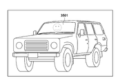
- the windshield when photographing an object inside a car as shown in FIG. 35A, at a certain polarization angle, the windshield reflects light as shown in region 3501 in FIG. 35B, making it impossible to photograph the interior of the car. Assume state.
- an imaging device provided with a polarizer array is used to take an image, and the acquired image is subjected to polarization removal processing to remove the reflected light, but the resolution is reduced.
- the present invention has been made in view of the above problems, and an object of the present invention is to enable more accurate polarization removal processing by using image signals having a plurality of different polarization characteristics obtained in one shot.
- the image processing apparatus of the present invention includes input means for inputting an image signal generated by photoelectrically converting a plurality of polarized light beams having different polarization angles, and an image signal based on the plurality of polarized light beams.
- a first processing means for obtaining, for each set of a plurality of image signals, the maximum value of the polarization intensity of the polarization components of the plurality of image signals and the polarization angle at which the polarization intensity is maximized; setting means for obtaining a target area to be subjected to polarization removal based on an image signal and setting a statistic area for obtaining statistics included in the target area; and the polarization of the set included in the statistic area.
- second processing means for obtaining a representative intensity that is the mode of the intensity and a representative angle that is the mode of the polarization angle; and correction means for performing a first correction process for correcting each image signal of the set according to the polarization angle of each image signal.
- more accurate polarization removal processing can be performed using image signals having a plurality of different polarization characteristics obtained in one shot.
- FIG. 2 is a block diagram showing the functional configuration of an imaging apparatus according to first to fourth, sixth, and eighth to tenth embodiments of the present invention
- FIG. 4 is a diagram showing an arrangement example of polarizing filters in the embodiment
- FIG. 4 is a diagram showing an arrangement example of polarizing filters in the embodiment
- FIG. 4 is a diagram showing an arrangement example of color filters and polarizing filters according to the embodiment
- FIG. 4 is a diagram showing an arrangement example of color filters and polarizing filters according to the embodiment
- 4A and 4B are diagrams showing an example of a subject according to the first embodiment
- FIG. 5A and 5B are views showing examples of images generated for different polarization directions when the subject shown in FIG. 4 is photographed;
- FIG. 5A and 5B are views showing examples of images generated for different polarization directions when the subject shown in FIG. 4 is photographed;
- FIG. 5A and 5B are views showing examples of images generated for different polarization directions when the subject shown in FIG. 4 is photographed;
- FIG. 5A and 5B are views showing examples of images generated for different polarization directions when the subject shown in FIG. 4 is photographed;
- FIG. 5A and 5B are views showing examples of images generated for different polarization directions when the subject shown in FIG. 4 is photographed;
- FIG. 10 is a diagram showing an example of a histogram showing the frequency of occurrence of polarization intensity and polarization angle according to the first to fourth embodiments;
- FIG. 10 is a diagram showing an example of a histogram showing the frequency of occurrence of polarization intensity and polarization angle according to the first to fourth embodiments;
- FIG. 10 is a diagram showing an example of a histogram showing the frequency of occurrence of polarization intensity and polarization angle according to the first to fourth embodiments;
- FIG. 10 is a diagram showing an example of a histogram showing the frequency of occurrence of polarization intensity and polarization angle according to the first to fourth embodiments;
- FIG. 10 is a diagram showing an example of a histogram showing the frequency of occurrence of polarization intensity and polarization angle according to the first to fourth embodiments;
- FIG. 10 is a diagram showing an example of a histogram showing the frequency of occurrence of polarization intensity and polarization angle according to the first to fourth embodiments;
- FIG. 10 is a diagram showing an example of a subject according to second to fourth embodiments;
- FIG. 8 is a flowchart showing a method for removing polarized light components according to the second embodiment; 10 is a flow chart showing a polarization component removal method according to the third embodiment.
- FIG. 11 is a diagram showing an example of exposure time and arrangement of polarizing filters for HDR synthesis in the fifth embodiment; The figure explaining HDR synthesis.
- FIG. 4 is a diagram for explaining a problem that occurs in HDR synthesis when a polarizing filter is used;
- FIG. 4 is a diagram for explaining a problem that occurs in HDR synthesis when a polarizing filter is used;
- FIG. 4 is a diagram for explaining a problem that occurs in HDR synthesis when a polarizing filter is used;
- FIG. 11 is a block diagram showing the functional configuration of an imaging device according to the fifth embodiment;
- FIG. 11 is a diagram showing gain conversion for obtaining an approximate function of polarization components according to the fifth embodiment;
- FIG. 15 is a flowchart of HDR synthesis processing using a depolarized image according to the fifth embodiment;
- FIG. 12 is a flow chart showing a method for removing polarization components according to the sixth embodiment;
- FIG. 11 is a diagram for explaining how to shift four local pixels in the sixth embodiment;
- 14 is a flowchart showing a method for removing polarized light components according to a modified example of the sixth embodiment;
- FIG. 14 is a diagram for explaining how to shift four local pixels in a modification of the sixth embodiment;
- FIG. 12 is a block diagram showing the functional configuration of an imaging device according to the seventh embodiment;
- FIG. 12 is a diagram for explaining an interpolation method according to the seventh embodiment;
- FIG. FIG. 12 is a diagram for explaining an interpolation method when color filters according to the seventh embodiment are arranged;
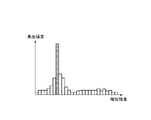
- FIG. 12 is a diagram for explaining a method for determining the presence or absence of an edge according to the seventh embodiment; 14 is a flowchart showing the flow of edge determination processing according to the seventh embodiment; FIG. 12 is a diagram showing an example of a subject having a plurality of reflecting surfaces according to the eighth embodiment; FIG. 20 is a diagram showing a histogram of polarization components when a subject has a plurality of reflecting surfaces according to the eighth embodiment; 14 is a flowchart showing a method for removing polarized light components according to the eighth embodiment; FIG. 12 is a diagram showing an example of a subject having a curved surface according to the ninth embodiment; FIG.
- FIG. 20 is a diagram showing a histogram of polarization components when a subject has a curved surface according to the ninth embodiment
- FIG. 20 is a diagram showing a histogram of polarization components when a subject has a curved surface according to the ninth embodiment
- 14 is a flowchart showing a method for removing polarized light components according to the ninth embodiment
- 14 is a flow chart showing a polarization component removal method according to the tenth embodiment.
- FIG. 13 is a diagram for explaining an edge determination method according to the tenth embodiment; A diagram for explaining the problem. A diagram for explaining the problem.
- FIG. 1 is a block diagram showing the functional configuration of an imaging device 100 in the first embodiment to which the image processing device of the present invention is applied, and shows extracted functions related to polarization component removal processing (correction processing). ing.
- the imaging device 100 is an example of a device that can input an image, reduce an arbitrary polarization component from the input image, and output the image.
- the imaging device 101 has a photoelectric conversion unit that converts incident light into an analog electrical signal, and an AD conversion unit that converts the converted analog signal into a digital signal.
- a plurality of polarizing filters with different polarization directions are arranged for each pixel on the imaging surface of the imaging device 101 .
- the image sensor 101 has a polarizing filter for each pixel.
- the polarizing filter of each pixel has a polarization direction different from that of the polarizing filter of the adjacent pixel, and the adjacent pixels can photoelectrically convert polarized light with different polarization directions.
- the pixel unit 112 in which the polarizing filters are arranged in this manner will be referred to as an "imaging plane polarization sensor 112".
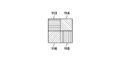
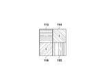
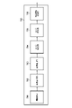
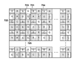
- the imaging plane polarization sensor 112 is provided with four types of polarizing filters each having a different polarization direction of 45°, each having four pixels as a set.
- a polarizing filter 113 with a polarizing angle of 0°, a polarizing filter 114 with a polarizing angle of 45°, a polarizing filter 115 with a polarizing angle of 90°, and a polarizing filter 116 with a polarizing angle of 135° are arranged.
- this set of 4 pixels will be referred to as "local 4 pixels”.
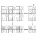
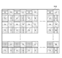
- a large number of local 4-pixels are periodically arranged as shown in FIG. 2A.
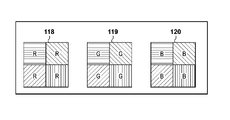
- FIG. 3A shows a case in which four local pixels covered by the filter 120 are arranged in a Bayer array as shown in FIG. 3A.
- FIGS. 2A, 2B, 3A, and 3B show an example of the imaging surface polarization sensor 112 that constitutes the imaging element 101, and it is possible to arbitrarily set the arrangement method and polarization direction of the polarizing filters. is. A method of combining the presence or absence of a polarizing filter is also conceivable.
- a single image is generated by extracting only the signals of pixels in which a polarizing filter in a certain polarization direction is arranged from the image signal of a single image obtained by photographing with the imaging surface polarization sensor 112. , an image can be obtained with polarized light having the same polarization direction as that of the polarizing filter.
- the polarizing filters 113 to 116 images in four different polarization directions can be obtained.
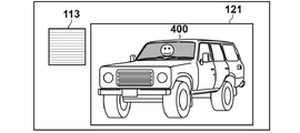
- FIG. 4 shows a subject in which a person 402 is in a car 401, and the area 400 is the windshield of the car.
- the reflected light in the region 400 is large. The details of the polarization characteristics of reflected light will be described later.
- FIG. 5A to 5D show examples of four polarized images obtained by separating the image signal obtained from the image sensor 101 for each polarization direction.
- FIG. 5A shows a polarization image 121 generated from image signals output only from the pixels in which the polarizing filters 113 with a polarization angle of 0° shown in FIGS. 2A and 2B are arranged.
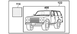
- FIG. 5B shows a polarization image 122 generated from image signals output only from pixels where the polarization filter 114 with a polarization angle of 45° is arranged.
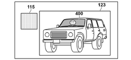
- FIG. 5C shows a polarization image 123 generated from image signals output only from pixels where the polarization filter 115 with a polarization angle of 90° is arranged.
- FIG. 5A shows a polarization image 121 generated from image signals output only from the pixels in which the polarizing filters 113 with a polarization angle of 0° shown in FIGS. 2A and 2B are arranged.
- FIG. 5B shows a polarization image
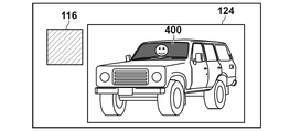
- 5D is a polarization image 124 generated from image signals output only from pixels in which the polarizing filter 116 with a polarization angle of 135° is arranged.
- the light reflected from the subject is expressed bright in areas where the polarizing filter is transmitted, and dark in areas where the light is blocked by the polarizing filter.
- the polarizing filter 114 with a polarizing angle of 45° transmits most of the light reflected from the windshield
- the area 400 shown in FIG. 5B is represented brightly.
- the polarizing filter 116 with a polarizing angle of 135° blocks most of the reflected light from the windshield, thus darkening the region 400 shown in FIG. 5D.
- the amount of reflected light transmitted by the polarizing filter 113 with a polarizing angle of 0° and the polarizing filter 115 with a polarizing angle of 90° is between that of the polarizing filter 114 and the polarizing filter 116, the region 400 shown in FIGS. Expressed with a medium brightness.
- the area where the brightness does not change in the polarized images in the four directions that is, the area excluding the area 400 is a non-polarized area in which the light is not polarized. That is, since the polarization angle cannot be adjusted for the non-polarized area, only the area 400 can adjust the magnitude of the reflected light in the subject example shown in FIG.
- a digital signal (image signal) generated by the imaging plane polarization sensor 112 in the imaging device 101 is input to the image acquisition unit 102 .
- the image acquisition unit 102 receives an image signal from the image sensor 101 and outputs the image signal to the area determination unit 103 and the approximate function calculation unit 104 .
- the area determination unit 103 totalizes the polarization characteristics obtained by the four local pixels when performing polarization removal processing, which will be described later, on the image signal input from the image acquisition unit 102, and determines a range (statistical area) for creating a histogram. . For example, if the difference between the maximum value and the minimum value of the four image signals (luminance values) output from each of the four local pixels is equal to or greater than a predetermined threshold value, the four local pixels are subject to depolarization. (hereinafter referred to as "polarization removal target area"). Then, an area obtained by collecting four adjacent local pixels determined to belong to the polarization removal target area is set as the polarization removal target area.
- the area determining unit 103 determines the obtained polarization removal target area as a statistical area. A region narrower than the target region for depolarization may be determined as the statistical region.
- Approximate function calculator 104 obtains polarization characteristics of polarized light for each of four local pixels from the image signal obtained by image obtaining unit 102 . Here, a method for obtaining polarization characteristics will be described.
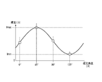
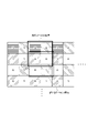
- FIG. 6A is a graph of an approximation function F( ⁇ ) representing the polarization characteristics of arbitrary four local pixels within the region 400.
- FIG. In the present embodiment, the luminance I( ⁇ ) component that changes for each polarization angle ⁇ is called a “polarization component”.
- the luminance I( ⁇ ) at polarization angles of 0°, 45°, 90°, and 135° is obtained from the image obtained by the image obtaining unit 102, and the obtained luminance I( ⁇ ) is plotted for each polarization angle ⁇ .
- I( ⁇ ) can be approximated by a sine or cosine function with a period of 180°. That is, an approximate function F( ⁇ ) can be obtained.
- the polarizing filters 113 to 116 shown in FIGS. 2A and 2B are used to utilize the brightness of four polarization angles.
- a function F( ⁇ ) can be generated.
- Equation (1) The approximation function F( ⁇ ) of this polarization component can be expressed by Equation (1).
- F( ⁇ ) Acos(2 ⁇ +2B)+C (1)
- A is the polarization intensity of the polarization component
- B is the polarization angle of the polarization component
- C is the offset component.
- F( ⁇ ) since the point with the minimum luminance Imin has the least polarized component, it represents the luminance of only the non-polarized component.
- the polarization component within the region 400 has the maximum luminance Imax when the polarization angle is 45° and the minimum luminance Imin when the polarization angle is 135°, as described above.
- FIG. 6B shows the polarization components (non-polarization components) of the non-polarization regions excluding the region 400 in FIGS. 5A to 5D, and the polarization components are 0 at all polarization angles ⁇ .
- the polarization component is set to 0 for convenience of explanation.
- the polarization intensity extraction unit 105 extracts intensity information (polarization intensity) of the polarization component from the approximation function F( ⁇ ) of the polarization component obtained by the approximation function calculation unit 104 , and outputs the intensity information (polarization intensity) to the polarization intensity histogram generation unit 106 .
- the polarization intensity indicates the amplitude of the approximation function F( ⁇ ), and the polarization intensity changes depending on the brightness of the polarized light.
- the polarization intensity histogram generation unit 106 totalizes the polarization intensity of each four local pixels extracted by the polarization intensity extraction unit 105 in the area determined by the area determination unit 103, and creates a histogram of the occurrence frequency.
- the polarization intensity mode value calculation unit 107 obtains the polarization intensity (representative intensity) that is the mode value in the histogram generated by the polarization intensity histogram generation unit 106 and outputs it to the polarization removal processing unit 111 .
- the polarization angle extraction unit 108 extracts the angle information (polarization angle) of the polarization component from the approximation function F( ⁇ ) of the polarization component obtained by the approximation function calculation unit 104 , and outputs the angle information (polarization angle) to the polarization angle histogram generation unit 109 .
- the polarization angle refers to the angle at which the approximation function F( ⁇ ) indicates the maximum luminance Imax.
- a polarization angle histogram generation unit 109 totalizes the polarization angles for each four local pixels extracted by the polarization angle extraction unit 108 in the statistical region determined by the region determination unit 103, and creates a histogram of the occurrence frequency.
- the polarization angle mode value calculation unit 110 obtains the polarization angle (representative angle) that is the mode value in the histogram generated by the polarization angle histogram generation unit 109 , and outputs it to the polarization removal processing unit 111 .
- the polarization removal processing unit 111 using the mode of the polarization intensity acquired by the polarization intensity mode calculation unit 107 and the mode of the polarization angle acquired by the polarization angle mode calculation unit 110, Determine the representative polarization properties at Then, the polarization component at each angle (here, 0°, 45°, 90°, 135°) is calculated from the determined representative polarization characteristics, and the polarization component is subtracted from each luminance value. For example, by substituting the mode of the polarization intensity Imode for A in Equation (1), the mode of the polarization angle ⁇ mode for B, and each angle for ⁇ , the polarization component shown in Equation (2) below is obtained. An approximation function can be obtained. Then, by substituting each polarization angle into the following equation (2), the polarization component of each polarization angle is obtained.
- the polarization component can be removed by subtracting the obtained polarization component from the luminance I( ⁇ ) obtained from each pixel in the polarization removal target area.
- the polarization removal image is obtained by appropriately removing the polarization component and maintaining the resolution.
- a non-polarized component edge such an edge due to a non-polarized component such as a person in a car
- polarized component edge an edge due to a polarized component such as reflected light
- an image signal is acquired from the imaging plane polarization sensor 112 .
- the approximation function calculation unit 104 obtains the approximation function F( ⁇ ) of the polarization component for each four local pixels based on the image signal acquired by the image acquisition unit 102 .
- the approximation function F( ⁇ ) of the polarization component a similar approximation function is calculated in regions having the same polarization characteristics. However, as shown in FIG.
- the approximation function obtained with the four local pixels including the edge of the non-polarized component in the region 400 is The polarization characteristics represented by F( ⁇ ) are different from the original polarization characteristics.
- the approximation function F(.theta.) obtained from the four local pixels that do not include the edge of the person in the area 400 is an approximation function that exhibits correct polarization characteristics.
- the polarization intensity and the polarization angle are calculated by the polarization intensity extraction unit 105 and the polarization angle extraction unit 108, respectively, from the approximation function F( ⁇ ) of the polarization component obtained for each four local pixels by the approximation function calculation unit 104. .
- a plurality of polarization characteristics are used when the polarization component is removed by the polarization removal processing unit 111, and a statistical region for acquiring the polarization characteristics is determined.
- a statistical region for acquiring the polarization characteristics is determined.
- it may be a polarization removal target area (for example, the area 400) from which the polarization component is to be removed, or a narrower area within the polarization removal target area.
- the polarization intensity and polarization angle acquired in S103 are totaled for each statistical area determined by the area determination unit 103 in S104. Then, the polarization intensity histogram generation unit 106 and the polarization angle histogram generation unit 109 use the aggregated polarization intensity and polarization angle to create histograms of occurrence frequencies.
- the polarization angle mode calculation unit 110 and the polarization intensity mode calculation unit 107 obtain the mode values (representative intensity and representative angle) in the histograms of the polarization intensity and the polarization angle created in S105, This is the representative polarization characteristic of the statistical area.
- the approximate function F( ⁇ ) obtained by the local 4 pixels without the edge of the non-polarized component behind the windshield becomes a function representing the correct polarization characteristic, This polarization characteristic has the largest number of components within the statistical domain.
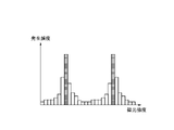
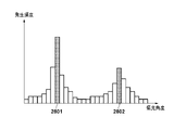
- the approximation function F( ⁇ ) calculated for the four local pixels including the edge of the non-polarized component differs from the polarization characteristics of the four local pixels not including the edge, and the approximation function F( ⁇ ) are different. Therefore, the histogram generated in this region is a histogram in which correct polarization characteristics and randomly distributed polarization characteristics including edges are mixed, as shown in FIGS. 8A and 8B. Therefore, by obtaining the mode of the polarization intensity and the polarization angle in the statistical region from the generated histogram and using it as the representative polarization characteristic, the influence of the edge component can be removed.
- polarization component removal processing (correction processing) is performed on all pixels in the polarization removal target area using the representative polarization characteristics of the corresponding statistical area.
- a region 901 in FIG. 9 is a region having reflected light with low luminance
- a region 902 is a region having reflection with high luminance.
- the same step numbers are assigned to the same processes as those shown in FIG. 7, and the description thereof will be omitted as appropriate.
- the boundary of polarized light may be included in the area subject to polarization removal.
- the histogram will include a plurality of peaks.
- the one with the higher occurrence frequency is selected as the representative polarization characteristic as the mode value in the statistical region, and in S107, the representative polarization characteristic is determined for each polarization removal target area. Depolarization is performed using However, when a plurality of polarization components having different polarization characteristics are included in the polarization removal target area, the polarization components cannot be correctly removed, which causes noise.
- the amplitude of the approximation function F( ⁇ ) differs between the regions 901 and 902 because the polarization intensity differs. Therefore, if the statistical region spans the regions 901 and 902, two types of polarization intensities are included in the statistical region.
- two peaks corresponding to regions 901 and 902 occur in the histogram of polarization intensity, as shown in FIG. 8C.
- the one with the larger value is selected as the mode and becomes the representative polarization characteristic of the statistical region.
- the polarization characteristic of the area 901 is selected as the representative polarization characteristic and the polarization component is removed, the polarization component will be removed incorrectly in the area 902 .
- a plurality of polarization-removed images from which the polarization components are removed are generated while changing the statistical region of the polarization components.
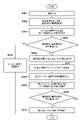
- S208 it is determined whether or not a predetermined number of polarization-removed images corrected by changing the statistical region have been created by the processing of S101 to S107. If the prescribed number of times has been reached, the process proceeds directly to S210. On the other hand, if the prescribed number of times has not been reached, the process advances to S209 to change the statistic area.
- a polarization removal target area such as area 901 and area 902, which includes a plurality of polarized lights with different polarization intensities and cannot successfully remove the polarized component, occurs.
- the statistical region is selected so that it does not include the polarization boundary according to the pattern of the statistical region, and a corrected image is created.
- synthesis processing such as averaging is performed on a plurality of depolarized images created by changing the statistical region to create one depolarized image.
- noise may occur due to depolarization in the wrong polarization component in each depolarization image, but by combining multiple images with different depolarization target areas, the effect of noise can be reduced and the correct image can be obtained. It can be approximated to depolarized images.
- a plurality of images are created from which the polarization component is removed by changing the size and position of the statistical region, and synthesis processing such as averaging is performed. That is, in the vicinity of the boundary between two types of reflected light, even if two types of polarized light are included in the area in the first statistical region, in the N-th statistical region, It may contain only one type of polarized light.
- a third embodiment of the invention will be described.
- the method for removing the polarization component by changing the size and position of the statistical area when a plurality of types of reflected light with different polarization intensities is included in the polarization removal target area has been described.
- another polarization component removal method will be described when a plurality of types of reflected light with different polarization intensities are included in the polarization removal target area.
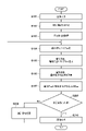
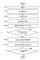
- FIG. 11 is a flow chart showing a polarization component removal method according to the third embodiment.
- the same step numbers are assigned to the same processes as those shown in FIG. 7, and the description thereof will be omitted as appropriate.
- the number of occurrence frequency peaks is acquired in the histogram of the polarization intensity acquired in S105.
- the subject as shown in FIG. 9 includes areas 901 and 902 in the statistical area, two types of polarization intensities are included. Therefore, as shown in FIG. and two peaks corresponding to region 902 occur.
- the histogram of polarization intensity has one peak.
- S307 it is determined whether or not the histogram of the polarization intensity includes a plurality of peaks. If there is one peak, in S106 and S107, the same processing as described in the first embodiment with reference to FIG. 7 is performed. , and depolarization is performed using the representative polarization characteristics of the statistical region.
- the process proceeds to S308, the polarization component is obtained based on the polarization intensity and the polarization angle obtained for every four local pixels, and the polarization component is removed.
- polarization removal is performed using the representative polarization characteristic for the image signal in the polarization removal target region. conduct.
- the polarization component is removed (correction processing) using the polarization intensity and the polarization angle determined for every four local pixels.
- the histogram of the polarization intensity in the polarization removal target area includes a plurality of peaks
- the polarization characteristics obtained for each of the four local pixels are used to determine the polarization component for each of the four local pixels.
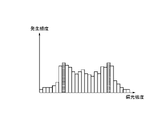
- the histogram of the polarization intensity does not always have a shape that allows multiple peaks to be determined as shown in FIG. 8C.
- peaks may not be clear as shown in FIG. 8D, and it may be difficult to accurately determine the number of peaks.
- the local 4 pixels for which the approximate function is calculated contains edges of polarized components and edges of non-polarized components, basically correct polarization characteristics cannot be calculated.
- the obtained approximation function becomes various approximation functions depending on the orientation of the edge, the included polarization characteristics, and the like. For example, when many edges of non-polarized components are included in the area to be depolarized, when a histogram of the polarization intensity is created, as shown in FIG. The histogram will look like it is distributed.
- the number of peaks fluctuates depending on the type of polarization intensity when creating a histogram. The number may not be determined.
- the mode is obtained from the histogram of the polarization angles, and the polarization intensity of the local 4 pixels having the polarization angle away from the mode is excluded from the polarization intensity histogram. That is, the polarization intensity histogram is regenerated using the polarization intensities of the four local pixels having polarization angles within a predetermined range from the mode. By doing so, it is possible to create a polarization intensity histogram that includes an edge within four pixels and excludes pixels for which an erroneous approximation function of the polarization characteristic is calculated. As a result, the shape of the polarization intensity histogram can be created using only correct polarization characteristics, and the determination accuracy in the third embodiment can be improved.
- FIG. 12 is a diagram showing the relationship between the arrangement of polarizing filters and the exposure time.
- the same arrangement as the polarizing filters 113 to 116 shown in FIGS. Let the exposure time of the pixels corresponding to 114 and 116 be short seconds (S).
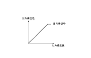
- FIGS. 13A to 13C a simple HDR synthesis method without using a polarizing filter will be described with reference to FIGS. 13A to 13C.
- the long-second (L) exposure condition is called a high-gain signal
- the short-second (S) exposure condition is called a low-gain signal.
- the solid line in FIG. 13A shows the relationship of the output luminance value to the input luminance value of the low gain signal.
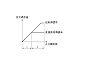
- the dashed line in FIG. 13B shows the relationship of the output luminance value to the input luminance value of the high gain signal
- the solid line in FIG. 13B shows the relationship of the output luminance value to the input luminance value of the high gain signal.
- FIG. 13C shows the low gain signal shown in FIG. 13A and the converted high gain signal shown in FIG. 13B on the same graph.
- the converted high-gain signal is used to generate the output luminance value
- the low-gain signal is used to generate the output luminance value, thereby performing HDR synthesis.
- the pixel value ratio and the exposure condition ratio do not match between the low-gain signal and the high-gain signal.
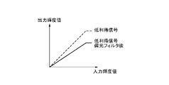
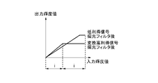
- FIGS. 13A to 13C show an example of the relationship between the input luminance value and the output luminance value when the HDR synthesis method shown in FIGS. 13A to 13C is applied when polarizing filters with different polarization angles are used.
- the dotted line in FIG. 14A shows the relationship between the output luminance value and the input luminance value of the low-gain signal indicated by the solid line in FIG. 13A
- the solid line in FIG. 4 shows the relationship of output luminance values to luminance values.
- the dashed line in FIG. 14B shows the relationship between the output luminance value and the input luminance value of the high-gain signal shown by the dashed line in FIG. 13B
- the dotted line in FIG. 4 shows the relationship of output luminance values to luminance values.
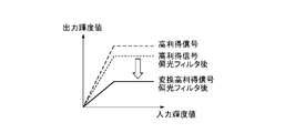
- the solid line in FIG. 14B is the output for the input luminance value of the converted high-gain signal after passing through the polarizing filter, which is converted by the ratio of the exposure conditions of the high-gain signal and the low-gain signal for the high-gain signal that has passed through the polarizing filter. It shows the relationship between luminance values.
- FIG. 14C shows the low-gain signal after passing through the polarizing filter indicated by the solid line in FIG. 14A and the converted high-gain signal after passing through the polarizing filter indicated by the solid line in FIG. 14B on the same graph.
- the converted high-gain signal after passing through the polarizing filter is used to generate the output luminance value
- the low-gain signal after passing the polarizing filter is used to generate the output luminance value generate a value.
- a step occurs at the boundary between the input luminance value area i and the input luminance value area ii.
- the fifth embodiment will describe HDR synthesis when the polarization removal method implemented in the first embodiment is performed.
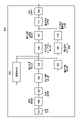
- FIG. 15 is a block diagram showing the functional configuration of an imaging device 500 according to the fifth embodiment, which implements HDR synthesis after polarization removal.
- the imaging device 500 is obtained by adding a gain conversion unit 501 and an HDR synthesizing unit 502 to the imaging device 100 shown in FIG. Numbers are attached and explanations are omitted.
- every four local pixels are covered with the polarizing filters 113 to 116, and the pixels covered with the polarizing filters 113 and 115 are exposed for a long time (L), and the polarized light is Assume that the pixels covered by filters 114 and 116 are exposed for a short time (S).
- L long time
- S short time
- a high gain signal and a low gain signal are acquired depending on the exposure time, but the present invention is not limited to this.
- the gain of the amplifier of the image sensor 101 may be used to change the sensitivity, or both the exposure time and the sensitivity may be changed.
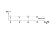
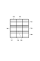
- FIG. 16 shows an example of pixel values (luminance values) obtained from four local pixels input to the gain conversion unit 501 .
- a pixel covered with a polarizing filter 113 having a polarization angle of 0° acquires a luminance IH_0° , which is a high-gain signal.
- a pixel with a polarization angle of 45° covered by the polarizing filter 114 acquires a luminance IL_45° , which is a low-gain signal.
- a luminance IH_90° which is a high-gain signal, is obtained from a pixel covered with a polarizing filter 115 having a polarization angle of 90°.
- a pixel covered with a polarizing filter 116 with a polarization angle of 135° acquires a luminance IL_135° , which is a low-gain signal.
- the gain conversion unit 501 converts each pixel into a value acquired with the same gain based on the exposure conditions of the four local pixels.
- luminance IH_0 ° and luminance IH_90° obtained as high-gain signals are converted into low-gain signals
- luminance IL_0° and luminance IL_90° are obtained as pixel values of the converted high-gain signals.
- the gain conversion method may be adjusted to a high gain signal or to a different gain, so the method of gain conversion is not limited to this.
- the image signal converted by the gain conversion unit 501 is depolarized by the process of the depolarization processing unit 111 from the area determination unit 103 described in the first embodiment, and the depolarized image is input to the HDR synthesis unit 502. be. Assuming that appropriate depolarization has been performed on the depolarized image input to the HDR synthesizing unit 502, the relationship shown in FIG. 13C can be obtained. Therefore, HDR synthesis is performed by using, for example, a converted high-gain signal in region i and a low-gain signal in region ii, as described with reference to FIGS. 13A to 13C. However, the method of HDR synthesis shown in this embodiment is an example, and is not limited to this. For example, a low-gain signal may be converted and used for HDR synthesis, or pixel values for each exposure condition may be appropriately selected or added for use.
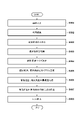
- the image acquisition unit 102 acquires image signals obtained under different exposure conditions from each of the four local pixels output from the image sensor 101 .
- the acquired image signal is gain-converted by the gain conversion unit 501 as described above, and adjusted so that the difference due to the exposure conditions of the acquired image signal is evened out, so that the image signal can be depolarized. Convert.
- polarization removal processing (correction processing) is performed using the methods described in the first to fourth embodiments.
- the HDR synthesis unit 502 performs HDR synthesis using the image signal from which the polarization component has been removed by the polarization removal processing unit 111 .
- image signals with different exposure conditions are acquired for four local pixels, and after adjusting the exposure conditions and removing polarized light, HDR synthesis is performed.
- HDR synthesis is performed.
- the imaging surface polarization sensor 112 is provided with polarizing filters having different polarization angles for a set of four local pixels, and photoelectrically converts incident light to output it as an image signal. be done. Then, using the luminance value of the output image signal, an approximation function of the luminance component (polarization component) that changes according to the polarization angle is obtained, and the polarization component is extracted.
- the edge portion of the object is within the four local pixels, the correct approximation function cannot be obtained for the four local pixels, or even if the approximation function is obtained, the polarization components of the four local pixels are It becomes false information completely different from the realm. Therefore, from the mode of the polarization information in the polarization removal target area, the polarization component for each polarization angle of the statistical area is obtained and applied to all four local pixels in the polarization removal target area.
- the polarization components of the four local pixels and the representative polarization component in the statistical area are compared, and it is determined whether the polarization intensity or the polarization angle is close. Processing in this embodiment will be described below with reference to the flowchart of FIG. 18 .
- a target image signal is input from the imaging plane polarization sensor 112, and in S602, as described in any one of the first to fourth embodiments, the maximum polarization intensity and polarization angle of the statistical region are detected. Get frequent values.
- the process proceeds to S606 to change the grouping of the local 4 pixels.
- the process proceeds to S606 to change the grouping of the local 4 pixels.
- four new local pixels are formed by shifting one pixel in any one of the vertical and horizontal directions.
- a new approximation function F( ⁇ ) of four local pixels is obtained, and the polarization intensity and the polarization angle are obtained.
- S608 the intensity difference and angle difference between the polarization intensity and polarization angle of the new four local pixels and the representative intensity and representative angle are obtained.
- the process returns to S606 to change the grouping of the local 4 pixels to another grouping. and repeat the above process.
- the local 4-pixel grouping is changed in any of the up, down, left, and right directions and the result is equal to or greater than the threshold value, for example, polarization removal is performed on the local 4-pixel grouping with the smallest difference.
- the image signal input in S601 is the output of an imaging surface polarization sensor with color filters, and has color information.
- each of the four local pixels is grouped for each color of R, G, and B, and the polarization intensity and polarization angle are calculated for each.
- each of the four local pixels is provided with the same color filter, so an image that has not yet been developed has a different output for each color.
- the G filter and the B filter are mixed, and the approximate function F ( ⁇ ) cannot be obtained.
- a white balance gain for polarization calculation is calculated for matching the polarization intensity of each of R, G, and B to G from the representative intensity calculated within the statistical region. Then, the R polarization intensity and the B polarization intensity are multiplied by the white balance gain for polarization calculation to make the polarization intensity almost the same as that of G, and then the approximate function F( ⁇ ) is calculated with the new four local pixels.
- the white balance gain is a gain value that is corrected to the reference white level by combining the R and B levels with respect to the G output of the white portion that serves as the reference.
- the white balance gain for polarization calculation is used to obtain the approximate function.
- a seventh embodiment of the invention will be described.
- a method of determining the type of edge in the image acquired by the imaging plane polarization sensor 112 and performing polarization removal (correction processing) according to the type of the determined edge will be described.
- FIG. 22 is a block diagram showing the functional configuration of an imaging device 700 according to the seventh embodiment.
- the imaging device 700 is a device capable of inputting and outputting an image.
- the image generation unit 703 separates the image signal acquired from the image sensor 101 by the image acquisition unit 102 for each polarization angle and generates each image. For example, when photographing the subject shown in FIG. 4, four polarized images 121 to 124 shown in FIGS. 5A to 5D are obtained. At this time, the resolution of the polarization image generated by the image generation unit 703 is 1/4 of the resolution of the image signal obtained by the image acquisition unit 102 from the imaging device 101 .
- FIG. 23 is a diagram for explaining the interpolation method, and shows the polarizing filters arranged in the same arrangement as the polarizing filters shown in FIG. 2A.
- the pixel value of the polarizing angle of 0° in the pixel of interest 711 to which the polarizing filter 114 having a polarizing angle of 45° is arranged is obtained by dividing the pixel value of the polarizing angle in the direction of 0° with the peripheral pixel 712 to which the polarizing filter 113 having a polarizing angle of 0° is arranged.
- An image is generated by interpolating by averaging 713 pixel values.
- the above interpolation method is only an example, and the interpolation method is not limited to this, and may refer to four surrounding pixels or pixels in an oblique direction.
- FIG. FIG. 24 is a diagram for explaining the interpolation method in that case, and shows the polarizing filters arranged in the same arrangement as the polarizing filters shown in FIG. 3A. In that case, first, interpolation is performed using neighboring pixels having the same color and the same polarization angle as the pixel value to be interpolated for the target pixel. Subsequently, by performing separation for each polarization angle, a plane image for each color and each polarization angle is generated.
- the pixel values of the four pixels of the peripheral pixels 722 to 725 in which the G color filter and the polarizing filter 114 are arranged are G pixel values are interpolated by taking the average value of .
- the plane image is separated for each polarization angle to generate a polarization image for each color and each polarization angle.
- the interpolation method described above is only an example, and the interpolation method may refer to eight surrounding pixels or to pixels in an oblique direction, and the interpolation method is not limited to this.
- the above image generation method is only an example, and the image to be generated may be only a G image, or may be a YUV image obtained by performing YUV conversion on an RGB image, so the image generation method is not limited to this.
- the edge detection unit 704 detects the presence or absence of an edge in the pixel of interest from the luminance difference with the surrounding pixels in the polarized image generated by the image generation unit 703 .
- the edge detection method will be specifically described with reference to FIG.
- FIG. 25 shows a total of 9 pixels, 3 pixels vertically and 3 pixels horizontally, of the polarization image 121 with a polarization angle of 0° generated by the image generation unit 703 .
- a method for determining whether or not there is an edge in the pixel of interest 730 will be described below.
- the average pixel value of the peripheral pixels 732, 735, and 737 is obtained and used as the first longitudinal average value.
- the average pixel values of the surrounding pixels 733, 731, and 738 are obtained and used as the second vertical direction average value.
- the average pixel value of the surrounding pixels 734, 736, and 739 is calculated and set as the third vertical direction average value.
- the average pixel values of the peripheral pixels 732, 733, and 734 are obtained and used as the first horizontal average value.
- the average pixel values of the surrounding pixels 735, 731, and 736 are obtained and used as the second horizontal direction average value.
- the average pixel values of the surrounding pixels 737, 738, and 739 are obtained and used as the third horizontal direction average value.
- the difference between the first vertical direction average value and the second vertical direction average value is defined as the first difference.
- the difference between the second vertical direction average value and the third vertical direction average value is defined as the second difference.
- the difference between the first horizontal average value and the second horizontal average value is defined as the third difference.
- a difference between the second horizontal average value and the third horizontal average value is defined as a fourth difference. If any of the first to fourth differences is less than a predetermined threshold, it is determined that there is no edge, and if any of the first to fourth differences is equal to or greater than the predetermined threshold, an edge Determined as present.
- edge detection method is only an example, and the edge detection method itself is not limited to this, since diagonal edge detection may be performed or a 3 ⁇ 3 edge detection filter may be used.
- the edge determination unit 705 compares the detection results of the edge detection unit 704 focusing on the pixels at the same position in the polarization image generated by the image generation unit 703, thereby determining the type of edge present in the four local pixels. .
- the determination result of the edge determination unit 705 is whether there is no edge, the edge of the non-polarized area (area other than the area 400 in FIG. 4) where the light is not polarized, the edge of the non-polarized component in the polarized area (area 400), Any of the edges of the polarization component in the polarization domain. A detailed edge determination method will be described later.
- a polarization characteristic processing unit 706 processes the polarization characteristics of the polarization image according to the determination result of the edge determination unit 705 . Specifically, when the edge determination unit 705 determines that there is no edge or determines that there is an edge in a non-polarized area, the polarization characteristic processing unit 706 calculates the polarization characteristic approximate function F( ⁇ ) is calculated, and depolarization is performed for every four local pixels. Alternatively, depolarization may be performed by a method similar to that of the first embodiment, or may be performed by a conventional method.
- the polarization characteristic processing unit 706 performs the processing described in the first embodiment, that is, the representative polarization characteristic in the divided area. is used to depolarize.
- the polarization characteristic processing unit 706 performs the process described in the second embodiment, that is, the polarization-removed images are processed in different area sizes. Depolarized light is removed by synthesizing.
- the processing of the polarization characteristic processing unit 706 in this embodiment is an example, and different processing may be performed according to the result of the edge determination unit 705 .
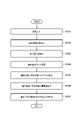
- FIG. 26 A method for determining the type of edge in the polarization image in the system described above will be described using the flowchart of FIG.
- the processing shown in FIG. 26 is processing performed by the edge determination unit 705 from the imaging element 101 shown in FIG.
- an image signal is acquired from the image sensor 101 .
- the image generation unit 703 generates a plurality of polarization images for each polarization angle from the image signal obtained in S701.
- the edge detection unit 704 performs edge detection on each of the polarization images generated in S702.
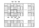
- the edge determination unit 705 determines whether or not there is a pixel determined to have an edge by the process of S703 in the edge detection process for the pixel signals output from the local 4 pixels 710 shown in FIG. If there is no pixel determined to have an edge, it is determined that the local 4 pixels 710 have no edge (S705), and the process proceeds to S711. If there is a pixel determined to have an edge, it is determined that an edge exists in the local 4 pixels 710, and the process proceeds to S706.
- S706 it is determined whether or not there is a pixel for which an edge has not been detected among the pixels 714 to 717 included in the local 4 pixels 710. If it is determined that there is an edge in pixels of all polarization angles (NO in S706), it is determined that the edge detected by the local 4 pixels 710 is an edge of the non-polarization area (S707), and the process proceeds to S711. If it is determined that there is no edge in the pixels of any polarization angle, it is determined that the edge present in the local 4 pixels 710 is the edge of the polarization region, and the process proceeds to S708.
- the pixel value of the pixel with the polarization angle determined to have an edge is compared with the pixel value of the pixel with the polarization angle determined to have no edge. If the pixel value of the pixel with the polarization angle determined to have an edge is less than or equal to the pixel value of the pixel with the polarization angle determined to have no edge, the edge present in the local 4 pixels 710 is determined to be the edge of the non-polarization component. (S709) and proceeds to S711.
- the edge present in the local 4 pixels 710 is the edge of the polarization component (S710). , to S711.
- S711 it is determined whether or not edge type determination processing has been performed for all four local pixels. If there are unprocessed four local pixels, the process returns to S704 and the above processing is performed for the next four local pixels.
- the seventh embodiment by comparing the edge detection results for each polarization angle, it is possible to determine the presence or absence of edges in the polarized image and the type of edges, thereby eliminating polarized light according to the subject or scene. (correction processing) can be performed.
- the representative polarization characteristics of the polarization removal target area are calculated, and the polarization component is removed while maintaining the resolution by subtracting the correct amount of polarization component for each angle in the polarization removal target area.
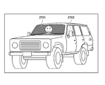
- the polarization component is uniformly removed using the representative polarization characteristics in the statistical area, the reflective surfaces having the same characteristics as the representative polarization characteristics will have good polarization. Although it can be removed, polarization cannot be removed sufficiently on a reflecting surface having characteristics different from the representative polarization characteristics.
- FIG. 28 shows a histogram of polarization angles when a combined area of the areas 2701 and 2702 is set as the statistical area.
- the area 2701 has one peak 2801, but the area 2701 and the area 2702 have different polarization angles.
- a histogram of polarization angles is created for statistical regions containing different polarization characteristics, multiple peaks appear.
- FIG. 29 is a flowchart showing processing for solving the above problem.
- the same reference numerals are assigned to the same processes as in FIG. 7, and the description thereof will be omitted as appropriate.
- the polarization angle mode value calculation unit 110 counts the number of peaks in the polarization angle histogram generated by the polarization angle histogram generation unit 109, and calculates the number of reflecting surfaces included in the statistical region from the counted number of peaks. judge. For example, when the number of peaks is 2, it is determined that two reflecting surfaces with different polarization characteristics are included. If it is determined that the number of reflecting surfaces is plural, the process returns to S104 and redetermines the size of the statistical area. At that time, the size of the statistical area is made smaller than the previously determined size. By repeating this process, the statistical area is made up of one reflecting surface.
- the mode is acquired from the histogram of the polarization intensity and the polarization angle generated in the statistical area, and in S107, based on the acquired mode, polarized light is removed within the depolarization target area.
- the statistical area and the polarization removal target area are the same.
- S802 it is determined whether or not polarization removal processing has been performed for all polarized regions. If there are regions that have not undergone polarization removal, the process returns to S104, and the above processing is repeated for the applicable regions.
- multiple histogram peaks may be formed due to subject edges, reflected light edges, noise, and the like.
- the number of peaks may be determined by smoothing the histogram or performing maximum likelihood estimation.
- depolarization correction processing
- depolarization can be favorably performed even when the subject includes a plurality of reflecting surfaces.
- the polarization component is removed while maintaining the resolution by calculating the representative polarization characteristic in the statistical region and subtracting the correct amount of polarization component for each polarization angle from the luminance value.
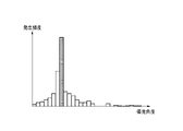
- the histogram becomes flat and depolarization is not sufficient at the edge of the curved surface.
- FIG. 31A is the histogram of the polarization angles created in the region 3001 of the windshield in FIG. Due to the curved surface of the windshield, the polarization angle calculated for every four local pixels in the area 3001 is not uniform, and the histogram becomes gentle.
- the edges of the windshield, where the curvature is significantly different have different polarization properties. Even if depolarization is performed based on the mode calculated from this histogram, good depolarization cannot be performed in areas outside the peak of the histogram, particularly at the edge of the windshield.
- FIG. 32 is a flowchart showing processing in the ninth embodiment.
- the same reference numbers are assigned to the same processes as in FIG. 7, and description thereof will be omitted as appropriate.
- the polarization angle mode calculation unit 110 compares the variance of the polarization angle histogram generated by the polarization angle histogram generation unit 109 with a threshold. Then, the process returns to S104 and re-determines the size of the statistical area. At this time, the statistical area is made smaller than the previously determined statistical area. By repeating this process, the statistical area is made up of reflective surfaces with similar curvatures.
- the mode is acquired from the histogram of polarization intensity and the histogram of polarization angle generated for the statistical region, and in S107, based on the acquired mode, polarized light is removed from the polarization correction target region. In this case, it is preferable that the statistical area and the polarization removal target area are the same.
- a region 3002 shown in FIG. 30 is within region 3001, but is a smaller region.
- a histogram of polarization angles created in this region 3002 is shown in FIG. 31B.
- the region 3002 is also within the curved surface, the curvature of the reflecting surface within the region 3002 is not significantly different, so the kurtosis of the histogram is increased.
- the reflecting surface is a curved surface in this way, narrowing the statistical area can increase the kurtosis of the histogram, and as a result, excellent depolarization (correction processing) can be performed.
- S902 it is determined whether or not polarization removal processing has been performed for all polarized regions. If there are regions that have not undergone polarization removal, the process returns to S104, and the above processing is repeated for the applicable regions.
- the statistical region includes a curved surface by comparing the variance of the histogram of the polarization angles with the threshold value.
- a probability distribution may be fitted by maximum likelihood estimation, and an index representing the variation and spread of the distribution may be used.
- the threshold may be set arbitrarily.
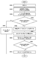
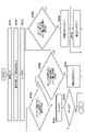
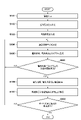
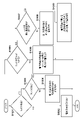
- FIG. 33 is a flow chart showing a polarization component removing method according to the tenth embodiment.
- the polarization intensity mode value calculation unit 107 determines the presence or absence of reflection. If the histogram of polarization intensity obtained by the polarization intensity histogram generation unit 106 has a peak of polarization intensity equal to or greater than a predetermined threshold value, it is determined that there is a reflecting area, and the process proceeds to S1003. Otherwise, it is determined that there is no reflecting area, the process advances to S1002, and the process ends without removing polarized light.
- S1003 it is determined whether or not there is an edge. If there is no edge, the process advances to S1004 to remove polarized light by the method for removing polarized light described in the first embodiment. On the other hand, if there is an edge, the process proceeds to S1005.
- the pixel value with the lowest level is used as the pixel value of the pixel of interest.
- S1007 it is determined whether the polarization intensity changes across the edge. If the polarization intensity does not change across the edge, the process advances to S1008 to remove the polarization using the polarization removal method described in the first embodiment. If the polarization intensity changes across the edge, the process proceeds to S1009.
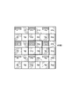
- FIG. 34 shows pixels referred to in edge determination in the tenth embodiment.
- the edge determination method in S1003, S1005, and S1007 will be described with reference to FIG.
- the pixels P33, P34, P43, and P44 in the four local pixels 1100 to be determined are used to obtain the approximation function F( ⁇ ) of the polarization characteristic. Let this be the first approximation function F 1 ( ⁇ ).
- the approximation function F( ⁇ ) of the polarization characteristic is obtained. Let this be the second approximation function F 2 ( ⁇ ).
- the left and right pixels P32, P42, P35, and P45 of the four local pixels 1100 are used to obtain the approximation function F( ⁇ ) of the polarization characteristic.
- the difference between the polarization angle of the first approximation function F 1 ( ⁇ ) and the polarization angle of the second approximation function F 2 ( ⁇ ) is defined as the first difference.
- the difference between the polarization angle of the first approximation function F 1 ( ⁇ ) and the polarization angle of the third approximation function F 3 ( ⁇ ) is defined as a second difference.
- the pixels P33, P34, P43, and P44 in the local 4 pixels 1100 is determined to have an edge. Also, in this case, since the direction of the edge is the vertical direction, it is determined in S1005 that the direction of the edge is known.
- both the first difference and the second difference are equal to or greater than the predetermined threshold, it is determined in S1003 that there is an edge between the pixels P33, P34, P43, and P44 in the four local pixels 1100, but S1005 , the direction of the edge is determined to be unknown.
- the polarization intensity obtained from the pixels P13, P14, P23, and P24 included in another local 4 pixel above the local 4 pixel 1100 is set as the first polarization intensity.
- the polarization intensity obtained from the pixels P31, P32, P41, and P42 included in another local 4 pixel on the left of the local 4 pixel 1100 is set as the second polarization intensity.
- the polarization intensity obtained from the pixels P35, P36, P45, and P46 included in another local 4 pixel on the right of the local 4 pixel 1100 is taken as the third polarization intensity.
- the polarization intensity obtained from the pixels P53, P54, P63, and P64 included in another local 4 pixel below the local 4 pixel 1100 is set as the fourth polarization intensity.
- the edge is detected if there is an edge between the pixels P33, P34, P43, and P44 in the local 4 pixels 1100. If the edge is detected if the difference between the first polarization intensity and the fourth polarization intensity is equal to or greater than a predetermined threshold. It is determined that there is a change in polarization intensity on the boundary. If the difference between the first polarization intensity and the fourth polarization intensity is less than a predetermined threshold, it is determined that there is no change in the polarization intensity across the edge.
- the edge is detected as the boundary. It is determined that there is a change in the polarization intensity corresponding to If the difference between the second polarization intensity and the third polarization intensity is less than a predetermined threshold, it is determined that there is no change in the polarization intensity across the edge.
- the polarization component calculated from the representative polarization characteristic is subtracted from the luminance value of each pixel. can be generated.
- edge determination using peripheral pixels and switching the polarization removal method, it is possible to appropriately remove polarization (correction processing) even for pixels that include edges of non-polarized components and edges of polarized components. is possible.
- the present invention may be applied to a system composed of a plurality of devices or to an apparatus composed of a single device.
- the present invention supplies a program that implements one or more functions of the above-described embodiments to a system or device via a network or a storage medium, and one or more processors in the computer of the system or device executes the program. It can also be realized by a process of reading and executing. It can also be implemented by a circuit (for example, ASIC) that implements one or more functions.
- a program that implements one or more functions of the above-described embodiments to a system or device via a network or a storage medium, and one or more processors in the computer of the system or device executes the program. It can also be realized by a process of reading and executing. It can also be implemented by a circuit (for example, ASIC) that implements one or more functions.
- ASIC application specific integrated circuit
Landscapes
- Engineering & Computer Science (AREA)
- Multimedia (AREA)
- Signal Processing (AREA)
- Physics & Mathematics (AREA)
- General Physics & Mathematics (AREA)
- Theoretical Computer Science (AREA)
- Computer Vision & Pattern Recognition (AREA)
- Spectroscopy & Molecular Physics (AREA)
- Image Processing (AREA)
- Blocking Light For Cameras (AREA)
- Camera Bodies And Camera Details Or Accessories (AREA)
- Studio Devices (AREA)
Priority Applications (1)
| Application Number | Priority Date | Filing Date | Title |
|---|---|---|---|
| US18/408,905 US12395745B2 (en) | 2021-07-12 | 2024-01-10 | Image processing apparatus and method, and image capturing apparatus |
Applications Claiming Priority (2)
| Application Number | Priority Date | Filing Date | Title |
|---|---|---|---|
| JP2021-115147 | 2021-07-12 | ||
| JP2021115147A JP7755402B2 (ja) | 2021-07-12 | 2021-07-12 | 画像処理装置及び方法、及び撮像装置 |
Related Child Applications (1)
| Application Number | Title | Priority Date | Filing Date |
|---|---|---|---|
| US18/408,905 Continuation US12395745B2 (en) | 2021-07-12 | 2024-01-10 | Image processing apparatus and method, and image capturing apparatus |
Publications (1)
| Publication Number | Publication Date |
|---|---|
| WO2023286496A1 true WO2023286496A1 (ja) | 2023-01-19 |
Family
ID=84920024
Family Applications (1)
| Application Number | Title | Priority Date | Filing Date |
|---|---|---|---|
| PCT/JP2022/022948 Ceased WO2023286496A1 (ja) | 2021-07-12 | 2022-06-07 | 画像処理装置及び方法、及び撮像装置 |
Country Status (3)
| Country | Link |
|---|---|
| US (1) | US12395745B2 (enExample) |
| JP (1) | JP7755402B2 (enExample) |
| WO (1) | WO2023286496A1 (enExample) |
Families Citing this family (6)
| Publication number | Priority date | Publication date | Assignee | Title |
|---|---|---|---|---|
| JP2024066718A (ja) * | 2022-11-02 | 2024-05-16 | キヤノン株式会社 | 画像処理装置、撮像装置、画像処理方法、およびプログラム |
| JP7719812B2 (ja) * | 2023-01-27 | 2025-08-06 | 株式会社平和 | 遊技機 |
| JP7642690B2 (ja) * | 2023-01-27 | 2025-03-10 | 株式会社平和 | 遊技機 |
| JP7731923B2 (ja) * | 2023-01-27 | 2025-09-01 | 株式会社平和 | 遊技機 |
| CN119697500B (zh) * | 2024-12-30 | 2025-12-16 | 天翼视联科技股份有限公司 | 一种视觉感知区域校准方法及系统 |
| CN119417831B (zh) * | 2025-01-07 | 2025-04-08 | 南京派光智慧感知信息技术有限公司 | 一种铁路隧道全景图合成监测方法、装置、设备及介质 |
Citations (4)
| Publication number | Priority date | Publication date | Assignee | Title |
|---|---|---|---|---|
| JP2015109625A (ja) * | 2013-05-15 | 2015-06-11 | 株式会社リコー | 画像処理システム |
| JP2017212678A (ja) * | 2016-05-27 | 2017-11-30 | キヤノン株式会社 | 画像処理装置、撮像装置、画像処理方法、プログラム、記憶媒体 |
| JP2020048140A (ja) * | 2018-09-21 | 2020-03-26 | キヤノン株式会社 | 撮影装置 |
| JP2021097348A (ja) * | 2019-12-18 | 2021-06-24 | キヤノン株式会社 | 撮像装置、制御方法およびプログラム |
Family Cites Families (6)
| Publication number | Priority date | Publication date | Assignee | Title |
|---|---|---|---|---|
| JP6391316B2 (ja) * | 2014-06-25 | 2018-09-19 | キヤノン株式会社 | 撮像装置 |
| JP6818444B2 (ja) | 2016-06-22 | 2021-01-20 | キヤノン株式会社 | 画像処理装置、撮像装置、画像処理プログラムおよび画像処理方法 |
| US11474334B2 (en) * | 2018-02-14 | 2022-10-18 | Sony Corporation | Observation device and observation method |
| US11637967B2 (en) * | 2018-04-09 | 2023-04-25 | Sony Corporation | Information processing apparatus, information processing method, and calibration apparatus |
| US11847762B2 (en) * | 2018-04-26 | 2023-12-19 | Sony Corporation | Information processing apparatus and method for processing information |
| JP7446804B2 (ja) * | 2019-12-18 | 2024-03-11 | キヤノン株式会社 | 撮像装置およびその制御方法、プログラム |
-
2021
- 2021-07-12 JP JP2021115147A patent/JP7755402B2/ja active Active
-
2022
- 2022-06-07 WO PCT/JP2022/022948 patent/WO2023286496A1/ja not_active Ceased
-
2024
- 2024-01-10 US US18/408,905 patent/US12395745B2/en active Active
Patent Citations (4)
| Publication number | Priority date | Publication date | Assignee | Title |
|---|---|---|---|---|
| JP2015109625A (ja) * | 2013-05-15 | 2015-06-11 | 株式会社リコー | 画像処理システム |
| JP2017212678A (ja) * | 2016-05-27 | 2017-11-30 | キヤノン株式会社 | 画像処理装置、撮像装置、画像処理方法、プログラム、記憶媒体 |
| JP2020048140A (ja) * | 2018-09-21 | 2020-03-26 | キヤノン株式会社 | 撮影装置 |
| JP2021097348A (ja) * | 2019-12-18 | 2021-06-24 | キヤノン株式会社 | 撮像装置、制御方法およびプログラム |
Also Published As
| Publication number | Publication date |
|---|---|
| US20240147080A1 (en) | 2024-05-02 |
| JP7755402B2 (ja) | 2025-10-16 |
| US12395745B2 (en) | 2025-08-19 |
| JP2023011342A (ja) | 2023-01-24 |
Similar Documents
| Publication | Publication Date | Title |
|---|---|---|
| WO2023286496A1 (ja) | 画像処理装置及び方法、及び撮像装置 | |
| JP4351825B2 (ja) | カラーのディジタルイメージを収集する方法 | |
| EP3414896B1 (en) | Combined hdr/ldr video streaming | |
| US7667738B2 (en) | Image processing device for detecting chromatic difference of magnification from raw data, image processing program, and electronic camera | |
| US8467088B2 (en) | Image signal processing apparatus, imaging apparatus, image signal processing method and computer program | |
| TWI428025B (zh) | Image processing apparatus and image processing method, image capturing apparatus and computer program product | |
| TWI333381B (enExample) | ||
| EP1209903B1 (en) | Method and system of noise removal for a sparsely sampled extended dynamic range image | |
| JP4668185B2 (ja) | 画像処理方法 | |
| JP5186517B2 (ja) | 撮像装置 | |
| US20030063185A1 (en) | Three-dimensional imaging with complementary color filter arrays | |
| JP5414691B2 (ja) | 画像処理装置及び画像処理方法 | |
| JP2004222231A (ja) | 画像処理装置および画像処理プログラム | |
| EP1484928B1 (en) | Imaging device | |
| JP2011171842A (ja) | 画像処理装置及び画像処理プログラム | |
| EP3799420A1 (en) | Image processing apparatus, method of processing image and program | |
| JP2004222233A (ja) | 画像処理装置および画像処理プログラム | |
| JP2008141658A (ja) | 電子カメラおよび画像処理装置 | |
| JP7445508B2 (ja) | 撮像装置 | |
| JP4993275B2 (ja) | 画像処理装置 | |
| Allen et al. | Digital cameras and scanners | |
| KR100741517B1 (ko) | 잡음에 강한 채널 간 상관관계를 고려한 고해상도 색상보간 방법 | |
| JP2013187711A (ja) | 画像処理装置、撮像装置及び画像処理方法 | |
| US20230169750A1 (en) | Method of and System for Capturing Color Images | |
| CN119316730A (zh) | 图像信号处理器 |
Legal Events
| Date | Code | Title | Description |
|---|---|---|---|
| NENP | Non-entry into the national phase |
Ref country code: DE |
|
| 122 | Ep: pct application non-entry in european phase |
Ref document number: 22841842 Country of ref document: EP Kind code of ref document: A1 |