WO2023286496A1 - Image processing device and method, and imaging device - Google Patents
Image processing device and method, and imaging device Download PDFInfo
- Publication number
- WO2023286496A1 WO2023286496A1 PCT/JP2022/022948 JP2022022948W WO2023286496A1 WO 2023286496 A1 WO2023286496 A1 WO 2023286496A1 JP 2022022948 W JP2022022948 W JP 2022022948W WO 2023286496 A1 WO2023286496 A1 WO 2023286496A1
- Authority
- WO
- WIPO (PCT)
- Prior art keywords
- polarization
- intensity
- angle
- histogram
- image
- Prior art date
Links
- 238000000034 method Methods 0.000 title claims description 126
- 238000012545 processing Methods 0.000 title claims description 119
- 238000003384 imaging method Methods 0.000 title claims description 47
- 230000010287 polarization Effects 0.000 claims abstract description 598
- 238000006243 chemical reaction Methods 0.000 claims abstract description 16
- 230000008569 process Effects 0.000 claims description 63
- 238000012937 correction Methods 0.000 claims description 41
- 230000015572 biosynthetic process Effects 0.000 claims description 26
- 238000003786 synthesis reaction Methods 0.000 claims description 26
- 230000008859 change Effects 0.000 claims description 12
- 230000002194 synthesizing effect Effects 0.000 claims description 10
- 238000001514 detection method Methods 0.000 claims description 7
- 230000002093 peripheral effect Effects 0.000 claims description 6
- 238000007476 Maximum Likelihood Methods 0.000 claims description 3
- 239000003086 colorant Substances 0.000 claims 2
- FFBHFFJDDLITSX-UHFFFAOYSA-N benzyl N-[2-hydroxy-4-(3-oxomorpholin-4-yl)phenyl]carbamate Chemical compound OC1=C(NC(=O)OCC2=CC=CC=C2)C=CC(=C1)N1CCOCC1=O FFBHFFJDDLITSX-UHFFFAOYSA-N 0.000 claims 1
- 238000003672 processing method Methods 0.000 claims 1
- 238000010586 diagram Methods 0.000 description 37
- 230000028161 membrane depolarization Effects 0.000 description 23
- 238000004364 calculation method Methods 0.000 description 17
- 238000003708 edge detection Methods 0.000 description 11
- 238000000605 extraction Methods 0.000 description 6
- 239000011521 glass Substances 0.000 description 4
- 230000004048 modification Effects 0.000 description 4
- 238000012986 modification Methods 0.000 description 4
- 238000012935 Averaging Methods 0.000 description 3
- 230000000694 effects Effects 0.000 description 3
- 239000000284 extract Substances 0.000 description 2
- 230000035945 sensitivity Effects 0.000 description 2
- 238000001308 synthesis method Methods 0.000 description 2
- 230000000295 complement effect Effects 0.000 description 1
- 238000007796 conventional method Methods 0.000 description 1
- 230000000593 degrading effect Effects 0.000 description 1
- 230000002999 depolarising effect Effects 0.000 description 1
- 230000005611 electricity Effects 0.000 description 1
- 238000009499 grossing Methods 0.000 description 1
- 230000007246 mechanism Effects 0.000 description 1
- 229910044991 metal oxide Inorganic materials 0.000 description 1
- 150000004706 metal oxides Chemical class 0.000 description 1
- 239000000203 mixture Substances 0.000 description 1
- 238000009877 rendering Methods 0.000 description 1
- 239000004065 semiconductor Substances 0.000 description 1
- 238000000926 separation method Methods 0.000 description 1
- 230000003595 spectral effect Effects 0.000 description 1
- XLYOFNOQVPJJNP-UHFFFAOYSA-N water Substances O XLYOFNOQVPJJNP-UHFFFAOYSA-N 0.000 description 1
Images


Classifications
-
- G—PHYSICS
- G03—PHOTOGRAPHY; CINEMATOGRAPHY; ANALOGOUS TECHNIQUES USING WAVES OTHER THAN OPTICAL WAVES; ELECTROGRAPHY; HOLOGRAPHY
- G03B—APPARATUS OR ARRANGEMENTS FOR TAKING PHOTOGRAPHS OR FOR PROJECTING OR VIEWING THEM; APPARATUS OR ARRANGEMENTS EMPLOYING ANALOGOUS TECHNIQUES USING WAVES OTHER THAN OPTICAL WAVES; ACCESSORIES THEREFOR
- G03B11/00—Filters or other obturators specially adapted for photographic purposes
-
- G—PHYSICS
- G03—PHOTOGRAPHY; CINEMATOGRAPHY; ANALOGOUS TECHNIQUES USING WAVES OTHER THAN OPTICAL WAVES; ELECTROGRAPHY; HOLOGRAPHY
- G03B—APPARATUS OR ARRANGEMENTS FOR TAKING PHOTOGRAPHS OR FOR PROJECTING OR VIEWING THEM; APPARATUS OR ARRANGEMENTS EMPLOYING ANALOGOUS TECHNIQUES USING WAVES OTHER THAN OPTICAL WAVES; ACCESSORIES THEREFOR
- G03B17/00—Details of cameras or camera bodies; Accessories therefor
- G03B17/02—Bodies
Definitions
- the present invention relates to an image processing apparatus and method, and an imaging apparatus, and more particularly to a technique for processing image signals generated by photoelectrically converting a plurality of polarized light beams with mutually different polarization angles.
- pixels multiple light-receiving elements (pixels) are arranged in an imaging device represented by CCD (Charge Coupled Device) and CMOS (Complementary Metal Oxide Semiconductor) sensors.
- CCD Charge Coupled Device
- CMOS Complementary Metal Oxide Semiconductor
- RGB Red
- G Green
- B Blue
- Polarization can be considered as the vibration direction of light, and it is known that light emitted from a light source has various vibration direction components (polarization directions) when reflected by a subject.
- vibration direction components polarization directions
- the polarized light component cannot be distinguished.
- Patent Document 1 proposes a technique for generating an output image corresponding to polarized light with a desired polarization angle using luminance values of a plurality of polarized images obtained by photoelectrically converting light with different polarization angles.
- this technique an approximation function of the luminance component (polarization component) that changes according to the polarization angle is obtained, the polarization component at a specific polarization angle is obtained based on the obtained approximation function, and the polarized light of the desired polarization angle is obtained.
- the polarization angle of the output image can be arbitrarily adjusted.
- Patent Document 1 as a method for acquiring a plurality of polarized images, a polarizer array in which four polarizers with different polarization directions are arranged as a set is integrally provided in an imaging device, and the polarized light is obtained from the output image signal. An example of generating four images with different angles is shown.
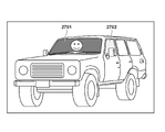
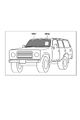
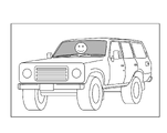
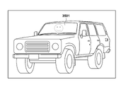
- the windshield when photographing an object inside a car as shown in FIG. 35A, at a certain polarization angle, the windshield reflects light as shown in region 3501 in FIG. 35B, making it impossible to photograph the interior of the car. Assume state.
- an imaging device provided with a polarizer array is used to take an image, and the acquired image is subjected to polarization removal processing to remove the reflected light, but the resolution is reduced.
- the present invention has been made in view of the above problems, and an object of the present invention is to enable more accurate polarization removal processing by using image signals having a plurality of different polarization characteristics obtained in one shot.
- the image processing apparatus of the present invention includes input means for inputting an image signal generated by photoelectrically converting a plurality of polarized light beams having different polarization angles, and an image signal based on the plurality of polarized light beams.
- a first processing means for obtaining, for each set of a plurality of image signals, the maximum value of the polarization intensity of the polarization components of the plurality of image signals and the polarization angle at which the polarization intensity is maximized; setting means for obtaining a target area to be subjected to polarization removal based on an image signal and setting a statistic area for obtaining statistics included in the target area; and the polarization of the set included in the statistic area.
- second processing means for obtaining a representative intensity that is the mode of the intensity and a representative angle that is the mode of the polarization angle; and correction means for performing a first correction process for correcting each image signal of the set according to the polarization angle of each image signal.
- more accurate polarization removal processing can be performed using image signals having a plurality of different polarization characteristics obtained in one shot.
- FIG. 2 is a block diagram showing the functional configuration of an imaging apparatus according to first to fourth, sixth, and eighth to tenth embodiments of the present invention
- FIG. 4 is a diagram showing an arrangement example of polarizing filters in the embodiment
- FIG. 4 is a diagram showing an arrangement example of polarizing filters in the embodiment
- FIG. 4 is a diagram showing an arrangement example of color filters and polarizing filters according to the embodiment
- FIG. 4 is a diagram showing an arrangement example of color filters and polarizing filters according to the embodiment
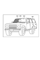
- 4A and 4B are diagrams showing an example of a subject according to the first embodiment
- FIG. 5A and 5B are views showing examples of images generated for different polarization directions when the subject shown in FIG. 4 is photographed;
- FIG. 5A and 5B are views showing examples of images generated for different polarization directions when the subject shown in FIG. 4 is photographed;
- FIG. 5A and 5B are views showing examples of images generated for different polarization directions when the subject shown in FIG. 4 is photographed;
- FIG. 5A and 5B are views showing examples of images generated for different polarization directions when the subject shown in FIG. 4 is photographed;
- FIG. 5A and 5B are views showing examples of images generated for different polarization directions when the subject shown in FIG. 4 is photographed;
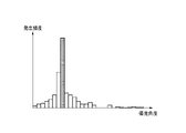
- FIG. 10 is a diagram showing an example of a histogram showing the frequency of occurrence of polarization intensity and polarization angle according to the first to fourth embodiments;
- FIG. 10 is a diagram showing an example of a histogram showing the frequency of occurrence of polarization intensity and polarization angle according to the first to fourth embodiments;
- FIG. 10 is a diagram showing an example of a histogram showing the frequency of occurrence of polarization intensity and polarization angle according to the first to fourth embodiments;
- FIG. 10 is a diagram showing an example of a histogram showing the frequency of occurrence of polarization intensity and polarization angle according to the first to fourth embodiments;
- FIG. 10 is a diagram showing an example of a histogram showing the frequency of occurrence of polarization intensity and polarization angle according to the first to fourth embodiments;
- FIG. 10 is a diagram showing an example of a histogram showing the frequency of occurrence of polarization intensity and polarization angle according to the first to fourth embodiments;
- FIG. 10 is a diagram showing an example of a subject according to second to fourth embodiments;
- FIG. 8 is a flowchart showing a method for removing polarized light components according to the second embodiment; 10 is a flow chart showing a polarization component removal method according to the third embodiment.
- FIG. 11 is a diagram showing an example of exposure time and arrangement of polarizing filters for HDR synthesis in the fifth embodiment; The figure explaining HDR synthesis.
- FIG. 4 is a diagram for explaining a problem that occurs in HDR synthesis when a polarizing filter is used;
- FIG. 4 is a diagram for explaining a problem that occurs in HDR synthesis when a polarizing filter is used;
- FIG. 4 is a diagram for explaining a problem that occurs in HDR synthesis when a polarizing filter is used;
- FIG. 11 is a block diagram showing the functional configuration of an imaging device according to the fifth embodiment;
- FIG. 11 is a diagram showing gain conversion for obtaining an approximate function of polarization components according to the fifth embodiment;
- FIG. 15 is a flowchart of HDR synthesis processing using a depolarized image according to the fifth embodiment;
- FIG. 12 is a flow chart showing a method for removing polarization components according to the sixth embodiment;
- FIG. 11 is a diagram for explaining how to shift four local pixels in the sixth embodiment;
- 14 is a flowchart showing a method for removing polarized light components according to a modified example of the sixth embodiment;
- FIG. 14 is a diagram for explaining how to shift four local pixels in a modification of the sixth embodiment;
- FIG. 12 is a block diagram showing the functional configuration of an imaging device according to the seventh embodiment;
- FIG. 12 is a diagram for explaining an interpolation method according to the seventh embodiment;
- FIG. FIG. 12 is a diagram for explaining an interpolation method when color filters according to the seventh embodiment are arranged;
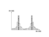
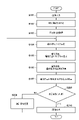
- FIG. 12 is a diagram for explaining a method for determining the presence or absence of an edge according to the seventh embodiment; 14 is a flowchart showing the flow of edge determination processing according to the seventh embodiment; FIG. 12 is a diagram showing an example of a subject having a plurality of reflecting surfaces according to the eighth embodiment; FIG. 20 is a diagram showing a histogram of polarization components when a subject has a plurality of reflecting surfaces according to the eighth embodiment; 14 is a flowchart showing a method for removing polarized light components according to the eighth embodiment; FIG. 12 is a diagram showing an example of a subject having a curved surface according to the ninth embodiment; FIG.
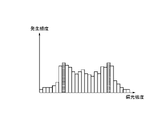
- FIG. 20 is a diagram showing a histogram of polarization components when a subject has a curved surface according to the ninth embodiment
- FIG. 20 is a diagram showing a histogram of polarization components when a subject has a curved surface according to the ninth embodiment
- 14 is a flowchart showing a method for removing polarized light components according to the ninth embodiment
- 14 is a flow chart showing a polarization component removal method according to the tenth embodiment.
- FIG. 13 is a diagram for explaining an edge determination method according to the tenth embodiment; A diagram for explaining the problem. A diagram for explaining the problem.
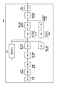
- FIG. 1 is a block diagram showing the functional configuration of an imaging device 100 in the first embodiment to which the image processing device of the present invention is applied, and shows extracted functions related to polarization component removal processing (correction processing). ing.
- the imaging device 100 is an example of a device that can input an image, reduce an arbitrary polarization component from the input image, and output the image.
- the imaging device 101 has a photoelectric conversion unit that converts incident light into an analog electrical signal, and an AD conversion unit that converts the converted analog signal into a digital signal.
- a plurality of polarizing filters with different polarization directions are arranged for each pixel on the imaging surface of the imaging device 101 .
- the image sensor 101 has a polarizing filter for each pixel.
- the polarizing filter of each pixel has a polarization direction different from that of the polarizing filter of the adjacent pixel, and the adjacent pixels can photoelectrically convert polarized light with different polarization directions.
- the pixel unit 112 in which the polarizing filters are arranged in this manner will be referred to as an "imaging plane polarization sensor 112".
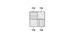
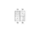
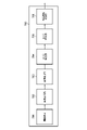
- the imaging plane polarization sensor 112 is provided with four types of polarizing filters each having a different polarization direction of 45°, each having four pixels as a set.
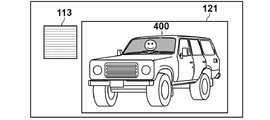
- a polarizing filter 113 with a polarizing angle of 0°, a polarizing filter 114 with a polarizing angle of 45°, a polarizing filter 115 with a polarizing angle of 90°, and a polarizing filter 116 with a polarizing angle of 135° are arranged.
- this set of 4 pixels will be referred to as "local 4 pixels”.
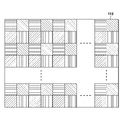
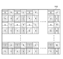
- a large number of local 4-pixels are periodically arranged as shown in FIG. 2A.
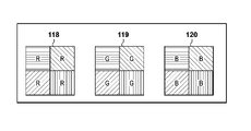
- FIG. 3A shows a case in which four local pixels covered by the filter 120 are arranged in a Bayer array as shown in FIG. 3A.
- FIGS. 2A, 2B, 3A, and 3B show an example of the imaging surface polarization sensor 112 that constitutes the imaging element 101, and it is possible to arbitrarily set the arrangement method and polarization direction of the polarizing filters. is. A method of combining the presence or absence of a polarizing filter is also conceivable.
- a single image is generated by extracting only the signals of pixels in which a polarizing filter in a certain polarization direction is arranged from the image signal of a single image obtained by photographing with the imaging surface polarization sensor 112. , an image can be obtained with polarized light having the same polarization direction as that of the polarizing filter.
- the polarizing filters 113 to 116 images in four different polarization directions can be obtained.
- FIG. 4 shows a subject in which a person 402 is in a car 401, and the area 400 is the windshield of the car.
- the reflected light in the region 400 is large. The details of the polarization characteristics of reflected light will be described later.
- FIG. 5A to 5D show examples of four polarized images obtained by separating the image signal obtained from the image sensor 101 for each polarization direction.
- FIG. 5A shows a polarization image 121 generated from image signals output only from the pixels in which the polarizing filters 113 with a polarization angle of 0° shown in FIGS. 2A and 2B are arranged.
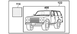
- FIG. 5B shows a polarization image 122 generated from image signals output only from pixels where the polarization filter 114 with a polarization angle of 45° is arranged.
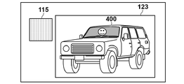
- FIG. 5C shows a polarization image 123 generated from image signals output only from pixels where the polarization filter 115 with a polarization angle of 90° is arranged.
- FIG. 5A shows a polarization image 121 generated from image signals output only from the pixels in which the polarizing filters 113 with a polarization angle of 0° shown in FIGS. 2A and 2B are arranged.
- FIG. 5B shows a polarization image
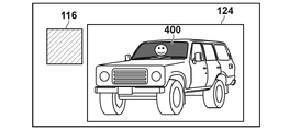
- 5D is a polarization image 124 generated from image signals output only from pixels in which the polarizing filter 116 with a polarization angle of 135° is arranged.
- the light reflected from the subject is expressed bright in areas where the polarizing filter is transmitted, and dark in areas where the light is blocked by the polarizing filter.
- the polarizing filter 114 with a polarizing angle of 45° transmits most of the light reflected from the windshield
- the area 400 shown in FIG. 5B is represented brightly.
- the polarizing filter 116 with a polarizing angle of 135° blocks most of the reflected light from the windshield, thus darkening the region 400 shown in FIG. 5D.
- the amount of reflected light transmitted by the polarizing filter 113 with a polarizing angle of 0° and the polarizing filter 115 with a polarizing angle of 90° is between that of the polarizing filter 114 and the polarizing filter 116, the region 400 shown in FIGS. Expressed with a medium brightness.
- the area where the brightness does not change in the polarized images in the four directions that is, the area excluding the area 400 is a non-polarized area in which the light is not polarized. That is, since the polarization angle cannot be adjusted for the non-polarized area, only the area 400 can adjust the magnitude of the reflected light in the subject example shown in FIG.
- a digital signal (image signal) generated by the imaging plane polarization sensor 112 in the imaging device 101 is input to the image acquisition unit 102 .
- the image acquisition unit 102 receives an image signal from the image sensor 101 and outputs the image signal to the area determination unit 103 and the approximate function calculation unit 104 .
- the area determination unit 103 totalizes the polarization characteristics obtained by the four local pixels when performing polarization removal processing, which will be described later, on the image signal input from the image acquisition unit 102, and determines a range (statistical area) for creating a histogram. . For example, if the difference between the maximum value and the minimum value of the four image signals (luminance values) output from each of the four local pixels is equal to or greater than a predetermined threshold value, the four local pixels are subject to depolarization. (hereinafter referred to as "polarization removal target area"). Then, an area obtained by collecting four adjacent local pixels determined to belong to the polarization removal target area is set as the polarization removal target area.
- the area determining unit 103 determines the obtained polarization removal target area as a statistical area. A region narrower than the target region for depolarization may be determined as the statistical region.
- Approximate function calculator 104 obtains polarization characteristics of polarized light for each of four local pixels from the image signal obtained by image obtaining unit 102 . Here, a method for obtaining polarization characteristics will be described.
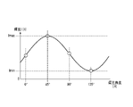
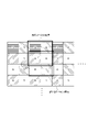
- FIG. 6A is a graph of an approximation function F( ⁇ ) representing the polarization characteristics of arbitrary four local pixels within the region 400.
- FIG. In the present embodiment, the luminance I( ⁇ ) component that changes for each polarization angle ⁇ is called a “polarization component”.
- the luminance I( ⁇ ) at polarization angles of 0°, 45°, 90°, and 135° is obtained from the image obtained by the image obtaining unit 102, and the obtained luminance I( ⁇ ) is plotted for each polarization angle ⁇ .
- I( ⁇ ) can be approximated by a sine or cosine function with a period of 180°. That is, an approximate function F( ⁇ ) can be obtained.
- the polarizing filters 113 to 116 shown in FIGS. 2A and 2B are used to utilize the brightness of four polarization angles.
- a function F( ⁇ ) can be generated.
- Equation (1) The approximation function F( ⁇ ) of this polarization component can be expressed by Equation (1).
- F( ⁇ ) Acos(2 ⁇ +2B)+C (1)
- A is the polarization intensity of the polarization component
- B is the polarization angle of the polarization component
- C is the offset component.
- F( ⁇ ) since the point with the minimum luminance Imin has the least polarized component, it represents the luminance of only the non-polarized component.
- the polarization component within the region 400 has the maximum luminance Imax when the polarization angle is 45° and the minimum luminance Imin when the polarization angle is 135°, as described above.
- FIG. 6B shows the polarization components (non-polarization components) of the non-polarization regions excluding the region 400 in FIGS. 5A to 5D, and the polarization components are 0 at all polarization angles ⁇ .
- the polarization component is set to 0 for convenience of explanation.
- the polarization intensity extraction unit 105 extracts intensity information (polarization intensity) of the polarization component from the approximation function F( ⁇ ) of the polarization component obtained by the approximation function calculation unit 104 , and outputs the intensity information (polarization intensity) to the polarization intensity histogram generation unit 106 .
- the polarization intensity indicates the amplitude of the approximation function F( ⁇ ), and the polarization intensity changes depending on the brightness of the polarized light.
- the polarization intensity histogram generation unit 106 totalizes the polarization intensity of each four local pixels extracted by the polarization intensity extraction unit 105 in the area determined by the area determination unit 103, and creates a histogram of the occurrence frequency.
- the polarization intensity mode value calculation unit 107 obtains the polarization intensity (representative intensity) that is the mode value in the histogram generated by the polarization intensity histogram generation unit 106 and outputs it to the polarization removal processing unit 111 .
- the polarization angle extraction unit 108 extracts the angle information (polarization angle) of the polarization component from the approximation function F( ⁇ ) of the polarization component obtained by the approximation function calculation unit 104 , and outputs the angle information (polarization angle) to the polarization angle histogram generation unit 109 .
- the polarization angle refers to the angle at which the approximation function F( ⁇ ) indicates the maximum luminance Imax.
- a polarization angle histogram generation unit 109 totalizes the polarization angles for each four local pixels extracted by the polarization angle extraction unit 108 in the statistical region determined by the region determination unit 103, and creates a histogram of the occurrence frequency.
- the polarization angle mode value calculation unit 110 obtains the polarization angle (representative angle) that is the mode value in the histogram generated by the polarization angle histogram generation unit 109 , and outputs it to the polarization removal processing unit 111 .
- the polarization removal processing unit 111 using the mode of the polarization intensity acquired by the polarization intensity mode calculation unit 107 and the mode of the polarization angle acquired by the polarization angle mode calculation unit 110, Determine the representative polarization properties at Then, the polarization component at each angle (here, 0°, 45°, 90°, 135°) is calculated from the determined representative polarization characteristics, and the polarization component is subtracted from each luminance value. For example, by substituting the mode of the polarization intensity Imode for A in Equation (1), the mode of the polarization angle ⁇ mode for B, and each angle for ⁇ , the polarization component shown in Equation (2) below is obtained. An approximation function can be obtained. Then, by substituting each polarization angle into the following equation (2), the polarization component of each polarization angle is obtained.
- the polarization component can be removed by subtracting the obtained polarization component from the luminance I( ⁇ ) obtained from each pixel in the polarization removal target area.
- the polarization removal image is obtained by appropriately removing the polarization component and maintaining the resolution.
- a non-polarized component edge such an edge due to a non-polarized component such as a person in a car
- polarized component edge an edge due to a polarized component such as reflected light
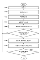
- an image signal is acquired from the imaging plane polarization sensor 112 .
- the approximation function calculation unit 104 obtains the approximation function F( ⁇ ) of the polarization component for each four local pixels based on the image signal acquired by the image acquisition unit 102 .
- the approximation function F( ⁇ ) of the polarization component a similar approximation function is calculated in regions having the same polarization characteristics. However, as shown in FIG.
- the approximation function obtained with the four local pixels including the edge of the non-polarized component in the region 400 is The polarization characteristics represented by F( ⁇ ) are different from the original polarization characteristics.
- the approximation function F(.theta.) obtained from the four local pixels that do not include the edge of the person in the area 400 is an approximation function that exhibits correct polarization characteristics.
- the polarization intensity and the polarization angle are calculated by the polarization intensity extraction unit 105 and the polarization angle extraction unit 108, respectively, from the approximation function F( ⁇ ) of the polarization component obtained for each four local pixels by the approximation function calculation unit 104. .
- a plurality of polarization characteristics are used when the polarization component is removed by the polarization removal processing unit 111, and a statistical region for acquiring the polarization characteristics is determined.
- a statistical region for acquiring the polarization characteristics is determined.
- it may be a polarization removal target area (for example, the area 400) from which the polarization component is to be removed, or a narrower area within the polarization removal target area.
- the polarization intensity and polarization angle acquired in S103 are totaled for each statistical area determined by the area determination unit 103 in S104. Then, the polarization intensity histogram generation unit 106 and the polarization angle histogram generation unit 109 use the aggregated polarization intensity and polarization angle to create histograms of occurrence frequencies.
- the polarization angle mode calculation unit 110 and the polarization intensity mode calculation unit 107 obtain the mode values (representative intensity and representative angle) in the histograms of the polarization intensity and the polarization angle created in S105, This is the representative polarization characteristic of the statistical area.
- the approximate function F( ⁇ ) obtained by the local 4 pixels without the edge of the non-polarized component behind the windshield becomes a function representing the correct polarization characteristic, This polarization characteristic has the largest number of components within the statistical domain.
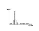
- the approximation function F( ⁇ ) calculated for the four local pixels including the edge of the non-polarized component differs from the polarization characteristics of the four local pixels not including the edge, and the approximation function F( ⁇ ) are different. Therefore, the histogram generated in this region is a histogram in which correct polarization characteristics and randomly distributed polarization characteristics including edges are mixed, as shown in FIGS. 8A and 8B. Therefore, by obtaining the mode of the polarization intensity and the polarization angle in the statistical region from the generated histogram and using it as the representative polarization characteristic, the influence of the edge component can be removed.
- polarization component removal processing (correction processing) is performed on all pixels in the polarization removal target area using the representative polarization characteristics of the corresponding statistical area.
- a region 901 in FIG. 9 is a region having reflected light with low luminance
- a region 902 is a region having reflection with high luminance.
- the same step numbers are assigned to the same processes as those shown in FIG. 7, and the description thereof will be omitted as appropriate.
- the boundary of polarized light may be included in the area subject to polarization removal.
- the histogram will include a plurality of peaks.
- the one with the higher occurrence frequency is selected as the representative polarization characteristic as the mode value in the statistical region, and in S107, the representative polarization characteristic is determined for each polarization removal target area. Depolarization is performed using However, when a plurality of polarization components having different polarization characteristics are included in the polarization removal target area, the polarization components cannot be correctly removed, which causes noise.
- the amplitude of the approximation function F( ⁇ ) differs between the regions 901 and 902 because the polarization intensity differs. Therefore, if the statistical region spans the regions 901 and 902, two types of polarization intensities are included in the statistical region.
- two peaks corresponding to regions 901 and 902 occur in the histogram of polarization intensity, as shown in FIG. 8C.
- the one with the larger value is selected as the mode and becomes the representative polarization characteristic of the statistical region.
- the polarization characteristic of the area 901 is selected as the representative polarization characteristic and the polarization component is removed, the polarization component will be removed incorrectly in the area 902 .
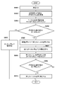
- a plurality of polarization-removed images from which the polarization components are removed are generated while changing the statistical region of the polarization components.
- S208 it is determined whether or not a predetermined number of polarization-removed images corrected by changing the statistical region have been created by the processing of S101 to S107. If the prescribed number of times has been reached, the process proceeds directly to S210. On the other hand, if the prescribed number of times has not been reached, the process advances to S209 to change the statistic area.
- a polarization removal target area such as area 901 and area 902, which includes a plurality of polarized lights with different polarization intensities and cannot successfully remove the polarized component, occurs.
- the statistical region is selected so that it does not include the polarization boundary according to the pattern of the statistical region, and a corrected image is created.
- synthesis processing such as averaging is performed on a plurality of depolarized images created by changing the statistical region to create one depolarized image.
- noise may occur due to depolarization in the wrong polarization component in each depolarization image, but by combining multiple images with different depolarization target areas, the effect of noise can be reduced and the correct image can be obtained. It can be approximated to depolarized images.
- a plurality of images are created from which the polarization component is removed by changing the size and position of the statistical region, and synthesis processing such as averaging is performed. That is, in the vicinity of the boundary between two types of reflected light, even if two types of polarized light are included in the area in the first statistical region, in the N-th statistical region, It may contain only one type of polarized light.
- a third embodiment of the invention will be described.
- the method for removing the polarization component by changing the size and position of the statistical area when a plurality of types of reflected light with different polarization intensities is included in the polarization removal target area has been described.
- another polarization component removal method will be described when a plurality of types of reflected light with different polarization intensities are included in the polarization removal target area.
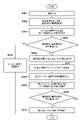
- FIG. 11 is a flow chart showing a polarization component removal method according to the third embodiment.
- the same step numbers are assigned to the same processes as those shown in FIG. 7, and the description thereof will be omitted as appropriate.
- the number of occurrence frequency peaks is acquired in the histogram of the polarization intensity acquired in S105.
- the subject as shown in FIG. 9 includes areas 901 and 902 in the statistical area, two types of polarization intensities are included. Therefore, as shown in FIG. and two peaks corresponding to region 902 occur.
- the histogram of polarization intensity has one peak.
- S307 it is determined whether or not the histogram of the polarization intensity includes a plurality of peaks. If there is one peak, in S106 and S107, the same processing as described in the first embodiment with reference to FIG. 7 is performed. , and depolarization is performed using the representative polarization characteristics of the statistical region.
- the process proceeds to S308, the polarization component is obtained based on the polarization intensity and the polarization angle obtained for every four local pixels, and the polarization component is removed.
- polarization removal is performed using the representative polarization characteristic for the image signal in the polarization removal target region. conduct.
- the polarization component is removed (correction processing) using the polarization intensity and the polarization angle determined for every four local pixels.
- the histogram of the polarization intensity in the polarization removal target area includes a plurality of peaks
- the polarization characteristics obtained for each of the four local pixels are used to determine the polarization component for each of the four local pixels.
- the histogram of the polarization intensity does not always have a shape that allows multiple peaks to be determined as shown in FIG. 8C.
- peaks may not be clear as shown in FIG. 8D, and it may be difficult to accurately determine the number of peaks.
- the local 4 pixels for which the approximate function is calculated contains edges of polarized components and edges of non-polarized components, basically correct polarization characteristics cannot be calculated.
- the obtained approximation function becomes various approximation functions depending on the orientation of the edge, the included polarization characteristics, and the like. For example, when many edges of non-polarized components are included in the area to be depolarized, when a histogram of the polarization intensity is created, as shown in FIG. The histogram will look like it is distributed.
- the number of peaks fluctuates depending on the type of polarization intensity when creating a histogram. The number may not be determined.
- the mode is obtained from the histogram of the polarization angles, and the polarization intensity of the local 4 pixels having the polarization angle away from the mode is excluded from the polarization intensity histogram. That is, the polarization intensity histogram is regenerated using the polarization intensities of the four local pixels having polarization angles within a predetermined range from the mode. By doing so, it is possible to create a polarization intensity histogram that includes an edge within four pixels and excludes pixels for which an erroneous approximation function of the polarization characteristic is calculated. As a result, the shape of the polarization intensity histogram can be created using only correct polarization characteristics, and the determination accuracy in the third embodiment can be improved.
- FIG. 12 is a diagram showing the relationship between the arrangement of polarizing filters and the exposure time.
- the same arrangement as the polarizing filters 113 to 116 shown in FIGS. Let the exposure time of the pixels corresponding to 114 and 116 be short seconds (S).
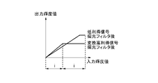
- FIGS. 13A to 13C a simple HDR synthesis method without using a polarizing filter will be described with reference to FIGS. 13A to 13C.
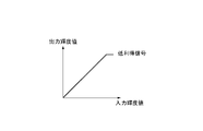
- the long-second (L) exposure condition is called a high-gain signal
- the short-second (S) exposure condition is called a low-gain signal.
- the solid line in FIG. 13A shows the relationship of the output luminance value to the input luminance value of the low gain signal.
- the dashed line in FIG. 13B shows the relationship of the output luminance value to the input luminance value of the high gain signal
- the solid line in FIG. 13B shows the relationship of the output luminance value to the input luminance value of the high gain signal.
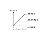
- FIG. 13C shows the low gain signal shown in FIG. 13A and the converted high gain signal shown in FIG. 13B on the same graph.
- the converted high-gain signal is used to generate the output luminance value
- the low-gain signal is used to generate the output luminance value, thereby performing HDR synthesis.
- the pixel value ratio and the exposure condition ratio do not match between the low-gain signal and the high-gain signal.
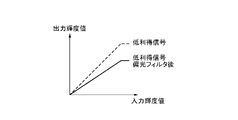
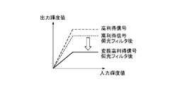
- FIGS. 13A to 13C show an example of the relationship between the input luminance value and the output luminance value when the HDR synthesis method shown in FIGS. 13A to 13C is applied when polarizing filters with different polarization angles are used.
- the dotted line in FIG. 14A shows the relationship between the output luminance value and the input luminance value of the low-gain signal indicated by the solid line in FIG. 13A
- the solid line in FIG. 4 shows the relationship of output luminance values to luminance values.
- the dashed line in FIG. 14B shows the relationship between the output luminance value and the input luminance value of the high-gain signal shown by the dashed line in FIG. 13B
- the dotted line in FIG. 4 shows the relationship of output luminance values to luminance values.
- the solid line in FIG. 14B is the output for the input luminance value of the converted high-gain signal after passing through the polarizing filter, which is converted by the ratio of the exposure conditions of the high-gain signal and the low-gain signal for the high-gain signal that has passed through the polarizing filter. It shows the relationship between luminance values.
- FIG. 14C shows the low-gain signal after passing through the polarizing filter indicated by the solid line in FIG. 14A and the converted high-gain signal after passing through the polarizing filter indicated by the solid line in FIG. 14B on the same graph.
- the converted high-gain signal after passing through the polarizing filter is used to generate the output luminance value
- the low-gain signal after passing the polarizing filter is used to generate the output luminance value generate a value.
- a step occurs at the boundary between the input luminance value area i and the input luminance value area ii.
- the fifth embodiment will describe HDR synthesis when the polarization removal method implemented in the first embodiment is performed.
- FIG. 15 is a block diagram showing the functional configuration of an imaging device 500 according to the fifth embodiment, which implements HDR synthesis after polarization removal.
- the imaging device 500 is obtained by adding a gain conversion unit 501 and an HDR synthesizing unit 502 to the imaging device 100 shown in FIG. Numbers are attached and explanations are omitted.
- every four local pixels are covered with the polarizing filters 113 to 116, and the pixels covered with the polarizing filters 113 and 115 are exposed for a long time (L), and the polarized light is Assume that the pixels covered by filters 114 and 116 are exposed for a short time (S).
- L long time
- S short time
- a high gain signal and a low gain signal are acquired depending on the exposure time, but the present invention is not limited to this.
- the gain of the amplifier of the image sensor 101 may be used to change the sensitivity, or both the exposure time and the sensitivity may be changed.
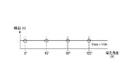
- FIG. 16 shows an example of pixel values (luminance values) obtained from four local pixels input to the gain conversion unit 501 .
- a pixel covered with a polarizing filter 113 having a polarization angle of 0° acquires a luminance IH_0° , which is a high-gain signal.
- a pixel with a polarization angle of 45° covered by the polarizing filter 114 acquires a luminance IL_45° , which is a low-gain signal.
- a luminance IH_90° which is a high-gain signal, is obtained from a pixel covered with a polarizing filter 115 having a polarization angle of 90°.
- a pixel covered with a polarizing filter 116 with a polarization angle of 135° acquires a luminance IL_135° , which is a low-gain signal.
- the gain conversion unit 501 converts each pixel into a value acquired with the same gain based on the exposure conditions of the four local pixels.
- luminance IH_0 ° and luminance IH_90° obtained as high-gain signals are converted into low-gain signals
- luminance IL_0° and luminance IL_90° are obtained as pixel values of the converted high-gain signals.
- the gain conversion method may be adjusted to a high gain signal or to a different gain, so the method of gain conversion is not limited to this.
- the image signal converted by the gain conversion unit 501 is depolarized by the process of the depolarization processing unit 111 from the area determination unit 103 described in the first embodiment, and the depolarized image is input to the HDR synthesis unit 502. be. Assuming that appropriate depolarization has been performed on the depolarized image input to the HDR synthesizing unit 502, the relationship shown in FIG. 13C can be obtained. Therefore, HDR synthesis is performed by using, for example, a converted high-gain signal in region i and a low-gain signal in region ii, as described with reference to FIGS. 13A to 13C. However, the method of HDR synthesis shown in this embodiment is an example, and is not limited to this. For example, a low-gain signal may be converted and used for HDR synthesis, or pixel values for each exposure condition may be appropriately selected or added for use.
- the image acquisition unit 102 acquires image signals obtained under different exposure conditions from each of the four local pixels output from the image sensor 101 .
- the acquired image signal is gain-converted by the gain conversion unit 501 as described above, and adjusted so that the difference due to the exposure conditions of the acquired image signal is evened out, so that the image signal can be depolarized. Convert.
- polarization removal processing (correction processing) is performed using the methods described in the first to fourth embodiments.
- the HDR synthesis unit 502 performs HDR synthesis using the image signal from which the polarization component has been removed by the polarization removal processing unit 111 .
- image signals with different exposure conditions are acquired for four local pixels, and after adjusting the exposure conditions and removing polarized light, HDR synthesis is performed.
- HDR synthesis is performed.
- the imaging surface polarization sensor 112 is provided with polarizing filters having different polarization angles for a set of four local pixels, and photoelectrically converts incident light to output it as an image signal. be done. Then, using the luminance value of the output image signal, an approximation function of the luminance component (polarization component) that changes according to the polarization angle is obtained, and the polarization component is extracted.
- the edge portion of the object is within the four local pixels, the correct approximation function cannot be obtained for the four local pixels, or even if the approximation function is obtained, the polarization components of the four local pixels are It becomes false information completely different from the realm. Therefore, from the mode of the polarization information in the polarization removal target area, the polarization component for each polarization angle of the statistical area is obtained and applied to all four local pixels in the polarization removal target area.
- the polarization components of the four local pixels and the representative polarization component in the statistical area are compared, and it is determined whether the polarization intensity or the polarization angle is close. Processing in this embodiment will be described below with reference to the flowchart of FIG. 18 .
- a target image signal is input from the imaging plane polarization sensor 112, and in S602, as described in any one of the first to fourth embodiments, the maximum polarization intensity and polarization angle of the statistical region are detected. Get frequent values.
- the process proceeds to S606 to change the grouping of the local 4 pixels.
- the process proceeds to S606 to change the grouping of the local 4 pixels.
- four new local pixels are formed by shifting one pixel in any one of the vertical and horizontal directions.
- a new approximation function F( ⁇ ) of four local pixels is obtained, and the polarization intensity and the polarization angle are obtained.
- S608 the intensity difference and angle difference between the polarization intensity and polarization angle of the new four local pixels and the representative intensity and representative angle are obtained.
- the process returns to S606 to change the grouping of the local 4 pixels to another grouping. and repeat the above process.
- the local 4-pixel grouping is changed in any of the up, down, left, and right directions and the result is equal to or greater than the threshold value, for example, polarization removal is performed on the local 4-pixel grouping with the smallest difference.
- the image signal input in S601 is the output of an imaging surface polarization sensor with color filters, and has color information.
- each of the four local pixels is grouped for each color of R, G, and B, and the polarization intensity and polarization angle are calculated for each.
- each of the four local pixels is provided with the same color filter, so an image that has not yet been developed has a different output for each color.
- the G filter and the B filter are mixed, and the approximate function F ( ⁇ ) cannot be obtained.
- a white balance gain for polarization calculation is calculated for matching the polarization intensity of each of R, G, and B to G from the representative intensity calculated within the statistical region. Then, the R polarization intensity and the B polarization intensity are multiplied by the white balance gain for polarization calculation to make the polarization intensity almost the same as that of G, and then the approximate function F( ⁇ ) is calculated with the new four local pixels.
- the white balance gain is a gain value that is corrected to the reference white level by combining the R and B levels with respect to the G output of the white portion that serves as the reference.
- the white balance gain for polarization calculation is used to obtain the approximate function.
- a seventh embodiment of the invention will be described.
- a method of determining the type of edge in the image acquired by the imaging plane polarization sensor 112 and performing polarization removal (correction processing) according to the type of the determined edge will be described.
- FIG. 22 is a block diagram showing the functional configuration of an imaging device 700 according to the seventh embodiment.
- the imaging device 700 is a device capable of inputting and outputting an image.
- the image generation unit 703 separates the image signal acquired from the image sensor 101 by the image acquisition unit 102 for each polarization angle and generates each image. For example, when photographing the subject shown in FIG. 4, four polarized images 121 to 124 shown in FIGS. 5A to 5D are obtained. At this time, the resolution of the polarization image generated by the image generation unit 703 is 1/4 of the resolution of the image signal obtained by the image acquisition unit 102 from the imaging device 101 .
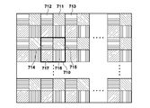
- FIG. 23 is a diagram for explaining the interpolation method, and shows the polarizing filters arranged in the same arrangement as the polarizing filters shown in FIG. 2A.
- the pixel value of the polarizing angle of 0° in the pixel of interest 711 to which the polarizing filter 114 having a polarizing angle of 45° is arranged is obtained by dividing the pixel value of the polarizing angle in the direction of 0° with the peripheral pixel 712 to which the polarizing filter 113 having a polarizing angle of 0° is arranged.
- An image is generated by interpolating by averaging 713 pixel values.
- the above interpolation method is only an example, and the interpolation method is not limited to this, and may refer to four surrounding pixels or pixels in an oblique direction.
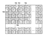
- FIG. FIG. 24 is a diagram for explaining the interpolation method in that case, and shows the polarizing filters arranged in the same arrangement as the polarizing filters shown in FIG. 3A. In that case, first, interpolation is performed using neighboring pixels having the same color and the same polarization angle as the pixel value to be interpolated for the target pixel. Subsequently, by performing separation for each polarization angle, a plane image for each color and each polarization angle is generated.
- the pixel values of the four pixels of the peripheral pixels 722 to 725 in which the G color filter and the polarizing filter 114 are arranged are G pixel values are interpolated by taking the average value of .
- the plane image is separated for each polarization angle to generate a polarization image for each color and each polarization angle.
- the interpolation method described above is only an example, and the interpolation method may refer to eight surrounding pixels or to pixels in an oblique direction, and the interpolation method is not limited to this.
- the above image generation method is only an example, and the image to be generated may be only a G image, or may be a YUV image obtained by performing YUV conversion on an RGB image, so the image generation method is not limited to this.
- the edge detection unit 704 detects the presence or absence of an edge in the pixel of interest from the luminance difference with the surrounding pixels in the polarized image generated by the image generation unit 703 .
- the edge detection method will be specifically described with reference to FIG.
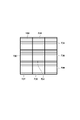
- FIG. 25 shows a total of 9 pixels, 3 pixels vertically and 3 pixels horizontally, of the polarization image 121 with a polarization angle of 0° generated by the image generation unit 703 .
- a method for determining whether or not there is an edge in the pixel of interest 730 will be described below.
- the average pixel value of the peripheral pixels 732, 735, and 737 is obtained and used as the first longitudinal average value.
- the average pixel values of the surrounding pixels 733, 731, and 738 are obtained and used as the second vertical direction average value.
- the average pixel value of the surrounding pixels 734, 736, and 739 is calculated and set as the third vertical direction average value.
- the average pixel values of the peripheral pixels 732, 733, and 734 are obtained and used as the first horizontal average value.
- the average pixel values of the surrounding pixels 735, 731, and 736 are obtained and used as the second horizontal direction average value.
- the average pixel values of the surrounding pixels 737, 738, and 739 are obtained and used as the third horizontal direction average value.
- the difference between the first vertical direction average value and the second vertical direction average value is defined as the first difference.
- the difference between the second vertical direction average value and the third vertical direction average value is defined as the second difference.
- the difference between the first horizontal average value and the second horizontal average value is defined as the third difference.
- a difference between the second horizontal average value and the third horizontal average value is defined as a fourth difference. If any of the first to fourth differences is less than a predetermined threshold, it is determined that there is no edge, and if any of the first to fourth differences is equal to or greater than the predetermined threshold, an edge Determined as present.
- edge detection method is only an example, and the edge detection method itself is not limited to this, since diagonal edge detection may be performed or a 3 ⁇ 3 edge detection filter may be used.
- the edge determination unit 705 compares the detection results of the edge detection unit 704 focusing on the pixels at the same position in the polarization image generated by the image generation unit 703, thereby determining the type of edge present in the four local pixels. .
- the determination result of the edge determination unit 705 is whether there is no edge, the edge of the non-polarized area (area other than the area 400 in FIG. 4) where the light is not polarized, the edge of the non-polarized component in the polarized area (area 400), Any of the edges of the polarization component in the polarization domain. A detailed edge determination method will be described later.
- a polarization characteristic processing unit 706 processes the polarization characteristics of the polarization image according to the determination result of the edge determination unit 705 . Specifically, when the edge determination unit 705 determines that there is no edge or determines that there is an edge in a non-polarized area, the polarization characteristic processing unit 706 calculates the polarization characteristic approximate function F( ⁇ ) is calculated, and depolarization is performed for every four local pixels. Alternatively, depolarization may be performed by a method similar to that of the first embodiment, or may be performed by a conventional method.
- the polarization characteristic processing unit 706 performs the processing described in the first embodiment, that is, the representative polarization characteristic in the divided area. is used to depolarize.
- the polarization characteristic processing unit 706 performs the process described in the second embodiment, that is, the polarization-removed images are processed in different area sizes. Depolarized light is removed by synthesizing.
- the processing of the polarization characteristic processing unit 706 in this embodiment is an example, and different processing may be performed according to the result of the edge determination unit 705 .
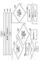
- FIG. 26 A method for determining the type of edge in the polarization image in the system described above will be described using the flowchart of FIG.
- the processing shown in FIG. 26 is processing performed by the edge determination unit 705 from the imaging element 101 shown in FIG.
- an image signal is acquired from the image sensor 101 .
- the image generation unit 703 generates a plurality of polarization images for each polarization angle from the image signal obtained in S701.
- the edge detection unit 704 performs edge detection on each of the polarization images generated in S702.
- the edge determination unit 705 determines whether or not there is a pixel determined to have an edge by the process of S703 in the edge detection process for the pixel signals output from the local 4 pixels 710 shown in FIG. If there is no pixel determined to have an edge, it is determined that the local 4 pixels 710 have no edge (S705), and the process proceeds to S711. If there is a pixel determined to have an edge, it is determined that an edge exists in the local 4 pixels 710, and the process proceeds to S706.
- S706 it is determined whether or not there is a pixel for which an edge has not been detected among the pixels 714 to 717 included in the local 4 pixels 710. If it is determined that there is an edge in pixels of all polarization angles (NO in S706), it is determined that the edge detected by the local 4 pixels 710 is an edge of the non-polarization area (S707), and the process proceeds to S711. If it is determined that there is no edge in the pixels of any polarization angle, it is determined that the edge present in the local 4 pixels 710 is the edge of the polarization region, and the process proceeds to S708.
- the pixel value of the pixel with the polarization angle determined to have an edge is compared with the pixel value of the pixel with the polarization angle determined to have no edge. If the pixel value of the pixel with the polarization angle determined to have an edge is less than or equal to the pixel value of the pixel with the polarization angle determined to have no edge, the edge present in the local 4 pixels 710 is determined to be the edge of the non-polarization component. (S709) and proceeds to S711.
- the edge present in the local 4 pixels 710 is the edge of the polarization component (S710). , to S711.
- S711 it is determined whether or not edge type determination processing has been performed for all four local pixels. If there are unprocessed four local pixels, the process returns to S704 and the above processing is performed for the next four local pixels.
- the seventh embodiment by comparing the edge detection results for each polarization angle, it is possible to determine the presence or absence of edges in the polarized image and the type of edges, thereby eliminating polarized light according to the subject or scene. (correction processing) can be performed.
- the representative polarization characteristics of the polarization removal target area are calculated, and the polarization component is removed while maintaining the resolution by subtracting the correct amount of polarization component for each angle in the polarization removal target area.
- the polarization component is uniformly removed using the representative polarization characteristics in the statistical area, the reflective surfaces having the same characteristics as the representative polarization characteristics will have good polarization. Although it can be removed, polarization cannot be removed sufficiently on a reflecting surface having characteristics different from the representative polarization characteristics.
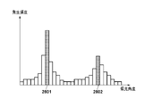
- FIG. 28 shows a histogram of polarization angles when a combined area of the areas 2701 and 2702 is set as the statistical area.
- the area 2701 has one peak 2801, but the area 2701 and the area 2702 have different polarization angles.
- a histogram of polarization angles is created for statistical regions containing different polarization characteristics, multiple peaks appear.
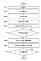
- FIG. 29 is a flowchart showing processing for solving the above problem.
- the same reference numerals are assigned to the same processes as in FIG. 7, and the description thereof will be omitted as appropriate.
- the polarization angle mode value calculation unit 110 counts the number of peaks in the polarization angle histogram generated by the polarization angle histogram generation unit 109, and calculates the number of reflecting surfaces included in the statistical region from the counted number of peaks. judge. For example, when the number of peaks is 2, it is determined that two reflecting surfaces with different polarization characteristics are included. If it is determined that the number of reflecting surfaces is plural, the process returns to S104 and redetermines the size of the statistical area. At that time, the size of the statistical area is made smaller than the previously determined size. By repeating this process, the statistical area is made up of one reflecting surface.
- the mode is acquired from the histogram of the polarization intensity and the polarization angle generated in the statistical area, and in S107, based on the acquired mode, polarized light is removed within the depolarization target area.
- the statistical area and the polarization removal target area are the same.
- S802 it is determined whether or not polarization removal processing has been performed for all polarized regions. If there are regions that have not undergone polarization removal, the process returns to S104, and the above processing is repeated for the applicable regions.
- multiple histogram peaks may be formed due to subject edges, reflected light edges, noise, and the like.
- the number of peaks may be determined by smoothing the histogram or performing maximum likelihood estimation.
- depolarization correction processing
- depolarization can be favorably performed even when the subject includes a plurality of reflecting surfaces.
- the polarization component is removed while maintaining the resolution by calculating the representative polarization characteristic in the statistical region and subtracting the correct amount of polarization component for each polarization angle from the luminance value.
- the histogram becomes flat and depolarization is not sufficient at the edge of the curved surface.
- FIG. 31A is the histogram of the polarization angles created in the region 3001 of the windshield in FIG. Due to the curved surface of the windshield, the polarization angle calculated for every four local pixels in the area 3001 is not uniform, and the histogram becomes gentle.
- the edges of the windshield, where the curvature is significantly different have different polarization properties. Even if depolarization is performed based on the mode calculated from this histogram, good depolarization cannot be performed in areas outside the peak of the histogram, particularly at the edge of the windshield.
- FIG. 32 is a flowchart showing processing in the ninth embodiment.
- the same reference numbers are assigned to the same processes as in FIG. 7, and description thereof will be omitted as appropriate.
- the polarization angle mode calculation unit 110 compares the variance of the polarization angle histogram generated by the polarization angle histogram generation unit 109 with a threshold. Then, the process returns to S104 and re-determines the size of the statistical area. At this time, the statistical area is made smaller than the previously determined statistical area. By repeating this process, the statistical area is made up of reflective surfaces with similar curvatures.
- the mode is acquired from the histogram of polarization intensity and the histogram of polarization angle generated for the statistical region, and in S107, based on the acquired mode, polarized light is removed from the polarization correction target region. In this case, it is preferable that the statistical area and the polarization removal target area are the same.
- a region 3002 shown in FIG. 30 is within region 3001, but is a smaller region.
- a histogram of polarization angles created in this region 3002 is shown in FIG. 31B.
- the region 3002 is also within the curved surface, the curvature of the reflecting surface within the region 3002 is not significantly different, so the kurtosis of the histogram is increased.
- the reflecting surface is a curved surface in this way, narrowing the statistical area can increase the kurtosis of the histogram, and as a result, excellent depolarization (correction processing) can be performed.
- S902 it is determined whether or not polarization removal processing has been performed for all polarized regions. If there are regions that have not undergone polarization removal, the process returns to S104, and the above processing is repeated for the applicable regions.
- the statistical region includes a curved surface by comparing the variance of the histogram of the polarization angles with the threshold value.
- a probability distribution may be fitted by maximum likelihood estimation, and an index representing the variation and spread of the distribution may be used.
- the threshold may be set arbitrarily.
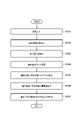
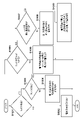
- FIG. 33 is a flow chart showing a polarization component removing method according to the tenth embodiment.
- the polarization intensity mode value calculation unit 107 determines the presence or absence of reflection. If the histogram of polarization intensity obtained by the polarization intensity histogram generation unit 106 has a peak of polarization intensity equal to or greater than a predetermined threshold value, it is determined that there is a reflecting area, and the process proceeds to S1003. Otherwise, it is determined that there is no reflecting area, the process advances to S1002, and the process ends without removing polarized light.
- S1003 it is determined whether or not there is an edge. If there is no edge, the process advances to S1004 to remove polarized light by the method for removing polarized light described in the first embodiment. On the other hand, if there is an edge, the process proceeds to S1005.
- the pixel value with the lowest level is used as the pixel value of the pixel of interest.
- S1007 it is determined whether the polarization intensity changes across the edge. If the polarization intensity does not change across the edge, the process advances to S1008 to remove the polarization using the polarization removal method described in the first embodiment. If the polarization intensity changes across the edge, the process proceeds to S1009.
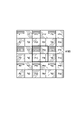
- FIG. 34 shows pixels referred to in edge determination in the tenth embodiment.
- the edge determination method in S1003, S1005, and S1007 will be described with reference to FIG.
- the pixels P33, P34, P43, and P44 in the four local pixels 1100 to be determined are used to obtain the approximation function F( ⁇ ) of the polarization characteristic. Let this be the first approximation function F 1 ( ⁇ ).
- the approximation function F( ⁇ ) of the polarization characteristic is obtained. Let this be the second approximation function F 2 ( ⁇ ).
- the left and right pixels P32, P42, P35, and P45 of the four local pixels 1100 are used to obtain the approximation function F( ⁇ ) of the polarization characteristic.
- the difference between the polarization angle of the first approximation function F 1 ( ⁇ ) and the polarization angle of the second approximation function F 2 ( ⁇ ) is defined as the first difference.
- the difference between the polarization angle of the first approximation function F 1 ( ⁇ ) and the polarization angle of the third approximation function F 3 ( ⁇ ) is defined as a second difference.
- the pixels P33, P34, P43, and P44 in the local 4 pixels 1100 is determined to have an edge. Also, in this case, since the direction of the edge is the vertical direction, it is determined in S1005 that the direction of the edge is known.
- both the first difference and the second difference are equal to or greater than the predetermined threshold, it is determined in S1003 that there is an edge between the pixels P33, P34, P43, and P44 in the four local pixels 1100, but S1005 , the direction of the edge is determined to be unknown.
- the polarization intensity obtained from the pixels P13, P14, P23, and P24 included in another local 4 pixel above the local 4 pixel 1100 is set as the first polarization intensity.
- the polarization intensity obtained from the pixels P31, P32, P41, and P42 included in another local 4 pixel on the left of the local 4 pixel 1100 is set as the second polarization intensity.
- the polarization intensity obtained from the pixels P35, P36, P45, and P46 included in another local 4 pixel on the right of the local 4 pixel 1100 is taken as the third polarization intensity.
- the polarization intensity obtained from the pixels P53, P54, P63, and P64 included in another local 4 pixel below the local 4 pixel 1100 is set as the fourth polarization intensity.
- the edge is detected if there is an edge between the pixels P33, P34, P43, and P44 in the local 4 pixels 1100. If the edge is detected if the difference between the first polarization intensity and the fourth polarization intensity is equal to or greater than a predetermined threshold. It is determined that there is a change in polarization intensity on the boundary. If the difference between the first polarization intensity and the fourth polarization intensity is less than a predetermined threshold, it is determined that there is no change in the polarization intensity across the edge.
- the edge is detected as the boundary. It is determined that there is a change in the polarization intensity corresponding to If the difference between the second polarization intensity and the third polarization intensity is less than a predetermined threshold, it is determined that there is no change in the polarization intensity across the edge.
- the polarization component calculated from the representative polarization characteristic is subtracted from the luminance value of each pixel. can be generated.
- edge determination using peripheral pixels and switching the polarization removal method, it is possible to appropriately remove polarization (correction processing) even for pixels that include edges of non-polarized components and edges of polarized components. is possible.
- the present invention may be applied to a system composed of a plurality of devices or to an apparatus composed of a single device.
- the present invention supplies a program that implements one or more functions of the above-described embodiments to a system or device via a network or a storage medium, and one or more processors in the computer of the system or device executes the program. It can also be realized by a process of reading and executing. It can also be implemented by a circuit (for example, ASIC) that implements one or more functions.
- a program that implements one or more functions of the above-described embodiments to a system or device via a network or a storage medium, and one or more processors in the computer of the system or device executes the program. It can also be realized by a process of reading and executing. It can also be implemented by a circuit (for example, ASIC) that implements one or more functions.
- ASIC application specific integrated circuit
Abstract
Image signals generated by photoelectric conversion of a plurality of polarized lights having mutually different polarization angles are input, and a plurality of image signals based on the plurality of polarized lights are used as a single set to determine, for each set, a maximum value of the polarization intensities of the polarization components of the plurality of image signals and a polarization angle at which the polarization intensity is at a maximum. Further, a region of interest for polarization removal is determined on the basis of the image signals, a statistics region included in the region of interest is set for obtaining statistics, and a representative intensity which is the mode value of the polarization intensities of the set included in the statistics region, and a representative angle which is the mode value of the polarization angles are determined. The representative intensity and the representative angle that have been determined are used to correct the image signals of a set included in the region of interest in accordance with the polarization angles of the respective image signals.
Description
本発明は、画像処理装置及び方法、及び撮像装置に関し、特に、互いに偏光角度が異なる複数の偏光光を光電変換することにより生成された画像信号を処理する技術に関する。
The present invention relates to an image processing apparatus and method, and an imaging apparatus, and more particularly to a technique for processing image signals generated by photoelectrically converting a plurality of polarized light beams with mutually different polarization angles.
従来、CCD(Charge Coupled device:電荷結合素子)や、CMOS(Complementary Metal Oxide Semiconductor:相補性金属酸化膜半導体)センサ等に代表される撮像素子には、複数の受光素子(画素)が配置されている。そして、各画素において光を電気に変換することで、光の強さ(輝度)を検出することができる。また、赤(R)、緑(G)、青(B)のうちいずれかの波長帯域の光を主に通過させるカラーフィルタを各画素に配置することで、可視光の波長(色)の光の強さのみを検出することができる。このような仕組みを用いることで、可視光の被写体を、映像信号(電気信号)として記憶装置に記録したり、表示装置に表示することが可能になる。
Conventionally, multiple light-receiving elements (pixels) are arranged in an imaging device represented by CCD (Charge Coupled Device) and CMOS (Complementary Metal Oxide Semiconductor) sensors. there is By converting light into electricity in each pixel, the intensity of light (luminance) can be detected. In addition, by arranging a color filter that mainly passes light in one of the wavelength bands of red (R), green (G), and blue (B) in each pixel, light of visible light wavelength (color) can only detect the strength of By using such a mechanism, it becomes possible to record a subject in visible light as a video signal (electrical signal) in a storage device or display it on a display device.
ところで、光は輝度や色等の要素のほかに、偏光と呼ばれる性質を持つ。偏光は、光の振動方向と考えることができ、光源から発した光は、被写体で反射する際に様々な振動方向成分(偏光方向)を持つことが知られている。しかし、実際は偏光された光と偏光していない光とが混合した光が眼に届くため、偏光した光の成分(偏光成分)を見分けることはできない。
By the way, in addition to factors such as brightness and color, light has a property called polarization. Polarization can be considered as the vibration direction of light, and it is known that light emitted from a light source has various vibration direction components (polarization directions) when reflected by a subject. However, in reality, since a mixture of polarized light and non-polarized light reaches the eye, the polarized light component (polarization component) cannot be distinguished.
一方で、この偏光の性質を利用することで、必要な反射光を際立たせたり、不必要な反射光を除去したりできることが一般的に知られている。例えば、水面やガラス面に映り込んでしまう映像を偏光(Polarized Light:PL)フィルタを使って除去することは、撮影のテクニックとしてよく利用されている。不要な反射光を抑えることでコントラストの協調効果を生み出したり、偏光強度から物体にかかる応力を可視化する等、従来とは異なる光の性質の利用方法として、今後も様々な応用が期待される。
On the other hand, it is generally known that by using this property of polarized light, it is possible to make necessary reflected light stand out and remove unnecessary reflected light. For example, using a polarized light (PL) filter to remove images reflected on water or glass surfaces is often used as a photography technique. Various applications are expected in the future as a way to use the properties of light that are different from the conventional ones, such as creating a contrast coordination effect by suppressing unnecessary reflected light and visualizing the stress applied to an object from the intensity of polarized light.
特許文献1では、異なる偏光角度の光を光電変換して取得した複数の偏光画像の輝度値を用いて、所望の偏光角度の偏光光に対応する出力画像を生成する技術が提案されている。この技術では、偏光角度に応じて変化する輝度成分(偏光成分)の近似関数を求め、求めた近似関数に基づいて特定の偏光角度における偏光成分を求め、所望の偏光角度の偏光光に対応する出力画像を生成する。この技術を用いることで、出力画像の偏光角度を任意に調整することができる。
Patent Document 1 proposes a technique for generating an output image corresponding to polarized light with a desired polarization angle using luminance values of a plurality of polarized images obtained by photoelectrically converting light with different polarization angles. In this technique, an approximation function of the luminance component (polarization component) that changes according to the polarization angle is obtained, the polarization component at a specific polarization angle is obtained based on the obtained approximation function, and the polarized light of the desired polarization angle is obtained. Generate an output image. By using this technique, the polarization angle of the output image can be arbitrarily adjusted.
また、特許文献1は、複数の偏光画像の取得方法として、偏光方向が異なる4つの偏光子を一組として配列された偏光子アレイを撮像素子に一体的に設け、出力された画像信号から偏光角度が異なる4枚の画像を生成する例を示している。
Further, in Patent Document 1, as a method for acquiring a plurality of polarized images, a polarizer array in which four polarizers with different polarization directions are arranged as a set is integrally provided in an imaging device, and the polarized light is obtained from the output image signal. An example of generating four images with different angles is shown.
しかしながら、特許文献1の技術を用いて、上述した偏光子アレイを用いて偏光角度の異なる画像を取得し、任意の偏光角度の偏光成分の除去を行う場合、次のような問題があった。すなわち、近似関数の最小輝度値が近似関数を求める際に使用した偏光子の各組に対応する4画素の画像信号に適用されてしまうため、偏光除去処理後の解像度が低下してしまう。
However, when using the technique of Patent Document 1 to acquire images with different polarization angles using the above-described polarizer array and remove polarization components with arbitrary polarization angles, there are the following problems. That is, since the minimum luminance value of the approximation function is applied to the image signals of the four pixels corresponding to each set of polarizers used when obtaining the approximation function, the resolution after polarization removal processing is degraded.
例えば、図35Aに示すような車の中の被写体を撮影する際に、ある偏光角度において、図35Bの領域3501に示すように、フロントガラスが光を反射して車の中の様子が撮影できない状態を想定する。この場合、偏光子アレイが設けられた撮像素子を用いて撮影を行い、取得した画像に対して偏光除去処理を行うことで反射光を取り除くことはできるが、解像度が低下してしまう。
For example, when photographing an object inside a car as shown in FIG. 35A, at a certain polarization angle, the windshield reflects light as shown in region 3501 in FIG. 35B, making it impossible to photograph the interior of the car. Assume state. In this case, an imaging device provided with a polarizer array is used to take an image, and the acquired image is subjected to polarization removal processing to remove the reflected light, but the resolution is reduced.
また、近似関数を求める際に使用した4画素の画像信号にエッジ成分が含まれている場合には、そもそも近似関数を正しく求めることができないため、エッジ成分を含む画像信号からは偏光成分を除去することができない。
Also, if edge components are included in the four-pixel image signals used to obtain the approximation function, the approximation function cannot be obtained correctly in the first place. Can not do it.
本発明は上記問題点を鑑みてなされたものであり、1回の撮影で得られる複数の異なる偏光特性を有する画像信号を用いて、より精度の高い偏光除去処理を行えるようにすることを目的とする。
The present invention has been made in view of the above problems, and an object of the present invention is to enable more accurate polarization removal processing by using image signals having a plurality of different polarization characteristics obtained in one shot. and
上記目的を達成するために、本発明の画像処理装置は、互いに偏光角度が異なる複数の偏光光を光電変換することにより生成された画像信号を入力する入力手段と、前記複数の偏光光に基づく複数の画像信号を1つのセットとして、各セットごとに前記複数の画像信号の偏光成分の偏光強度の最大値と、前記偏光強度が最大となる偏光角度とを求める第1の処理手段と、前記画像信号に基づいて、偏光除去を行う対象となる対象領域を求め、当該対象領域に含まれる、統計を取るための統計領域を設定する設定手段と、前記統計領域に含まれる前記セットの前記偏光強度の最頻値である代表強度と、前記偏光角度の最頻値である代表角度とを求める第2の処理手段と、前記代表強度と前記代表角度とを用いて、前記対象領域に含まれる前記セットの各画像信号を、当該各画像信号の偏光角度に応じて補正する第1の補正処理を行う補正手段とを有する。
To achieve the above object, the image processing apparatus of the present invention includes input means for inputting an image signal generated by photoelectrically converting a plurality of polarized light beams having different polarization angles, and an image signal based on the plurality of polarized light beams. a first processing means for obtaining, for each set of a plurality of image signals, the maximum value of the polarization intensity of the polarization components of the plurality of image signals and the polarization angle at which the polarization intensity is maximized; setting means for obtaining a target area to be subjected to polarization removal based on an image signal and setting a statistic area for obtaining statistics included in the target area; and the polarization of the set included in the statistic area. second processing means for obtaining a representative intensity that is the mode of the intensity and a representative angle that is the mode of the polarization angle; and correction means for performing a first correction process for correcting each image signal of the set according to the polarization angle of each image signal.
本発明によれば、1回の撮影で得られる複数の異なる偏光特性を有する画像信号を用いて、より精度の高い偏光除去処理を行うことができる。
According to the present invention, more accurate polarization removal processing can be performed using image signals having a plurality of different polarization characteristics obtained in one shot.
本発明のその他の特徴及び利点は、添付図面を参照とした以下の説明により明らかになるであろう。なお、添付図面においては、同じ若しくは同様の構成には、同じ参照番号を付す。
Other features and advantages of the present invention will become apparent from the following description with reference to the accompanying drawings. In the accompanying drawings, the same or similar configurations are given the same reference numerals.
添付図面は明細書に含まれ、その一部を構成し、本発明の実施の形態を示し、その記述と共に本発明の原理を説明するために用いられる。
The accompanying drawings, which are incorporated in and constitute a part of the specification, illustrate embodiments of the present invention and, together with the description, are used to explain the principles of the present invention.
添付図面は明細書に含まれ、その一部を構成し、本発明の実施の形態を示し、その記述と共に本発明の原理を説明するために用いられる。
本発明の第1乃至第4、第6、及び、第8乃至第10の実施形態に係る撮像装置の機能構成を示すブロック図。
実施形態における偏光フィルタの配置例を示す図。
実施形態における偏光フィルタの配置例を示す図。
実施形態におけるカラーフィルタ及び偏光フィルタの配置例を示す図。
実施形態におけるカラーフィルタ及び偏光フィルタの配置例を示す図。
第1の実施形態における被写体例を示す図。
図4に示す被写体を撮影した場合に異なる偏光方向毎に生成された画像の例を示す図。
図4に示す被写体を撮影した場合に異なる偏光方向毎に生成された画像の例を示す図。
図4に示す被写体を撮影した場合に異なる偏光方向毎に生成された画像の例を示す図。
図4に示す被写体を撮影した場合に異なる偏光方向毎に生成された画像の例を示す図。
第1の実施形態に係る偏光成分の近似関数を表したグラフ。
第1の実施形態に係る偏光成分の近似関数を表したグラフ。
第1の実施形態に係る偏光成分の除去方法を示すフローチャート。
第1乃至第4の実施形態に係る偏光強度及び偏光角度の発生頻度を示すヒストグラムの例を示す図。
第1乃至第4の実施形態に係る偏光強度及び偏光角度の発生頻度を示すヒストグラムの例を示す図。
第1乃至第4の実施形態に係る偏光強度及び偏光角度の発生頻度を示すヒストグラムの例を示す図。
第1乃至第4の実施形態に係る偏光強度及び偏光角度の発生頻度を示すヒストグラムの例を示す図。
第2乃至第4の実施形態における被写体例を示す図。
第2の実施形態に係る偏光成分の除去方法を示すフローチャート。
第3の実施形態に係る偏光成分の除去方法を示すフローチャート。
第5の実施形態におけるHDR合成のための露光時間と偏光フィルタの配置例を示す図。
HDR合成を説明する図。
HDR合成を説明する図。
HDR合成を説明する図。
偏光フィルタを用いた場合にHDR合成で起こる課題を説明する図。
偏光フィルタを用いた場合にHDR合成で起こる課題を説明する図。
偏光フィルタを用いた場合にHDR合成で起こる課題を説明する図。
第5の実施形態に係る撮像装置の機能構成を示すブロック図。
第5の実施形態に係る偏光成分の近似関数取得に向けた利得変換を示す図。
第5の実施形態に係る偏光除去画像を用いたHDR合成処理のフローチャート。
第6の実施形態に係る偏光成分の除去方法を示すフローチャート。
第6の実施形態におけるローカル4画素のずらし方を説明する図。
第6の実施形態の変形例に係る偏光成分の除去方法を示すフローチャート。
第6の実施形態の変形例におけるローカル4画素のずらし方を説明する図。
第7の実施形態に係る撮像装置の機能構成を示すブロック図。
第7の実施形態に係る補間方法を説明するための図。
第7の実施形態に係るカラーフィルタが配された場合の補間方法を説明するための図。
第7の実施形態に係るエッジ有無の判定方法を説明するための図。
第7の実施形態に係るエッジ判別処理の流れを示すフローチャート。
第8の実施形態に係る複数の反射面を有する被写体例を示す図。
第8の実施形態に係る被写体が複数の反射面を有する場合の偏光成分のヒストグラムを示す図。
第8の実施形態に係る偏光成分の除去方法を示すフローチャート。
第9の実施形態に係る曲面を有する被写体例を示す図。
第9の実施形態に係る被写体が曲面を有する場合の偏光成分のヒストグラムを示す図。
第9の実施形態に係る被写体が曲面を有する場合の偏光成分のヒストグラムを示す図。
第9の実施形態に係る偏光成分の除去方法を示すフローチャート。
第10の実施形態に係る偏光成分の除去方法を示すフローチャート。
第10の実施形態におけるエッジの判定方法を説明するための図。
課題を説明するための図。
課題を説明するための図。
The accompanying drawings, which are incorporated in and constitute a part of the specification, illustrate embodiments of the invention and, together with the description, serve to explain the principles of the invention.
FIG. 2 is a block diagram showing the functional configuration of an imaging apparatus according to first to fourth, sixth, and eighth to tenth embodiments of the present invention; FIG. 4 is a diagram showing an arrangement example of polarizing filters in the embodiment; FIG. 4 is a diagram showing an arrangement example of polarizing filters in the embodiment; FIG. 4 is a diagram showing an arrangement example of color filters and polarizing filters according to the embodiment; FIG. 4 is a diagram showing an arrangement example of color filters and polarizing filters according to the embodiment; 4A and 4B are diagrams showing an example of a subject according to the first embodiment; FIG. 5A and 5B are views showing examples of images generated for different polarization directions when the subject shown in FIG. 4 is photographed; FIG. 5A and 5B are views showing examples of images generated for different polarization directions when the subject shown in FIG. 4 is photographed; FIG. 5A and 5B are views showing examples of images generated for different polarization directions when the subject shown in FIG. 4 is photographed; FIG. 5A and 5B are views showing examples of images generated for different polarization directions when the subject shown in FIG. 4 is photographed; FIG. 5 is a graph showing an approximation function of polarization components according to the first embodiment; 5 is a graph showing an approximation function of polarization components according to the first embodiment; 4 is a flowchart showing a method for removing polarized light components according to the first embodiment; FIG. 10 is a diagram showing an example of a histogram showing the frequency of occurrence of polarization intensity and polarization angle according to the first to fourth embodiments; FIG. 10 is a diagram showing an example of a histogram showing the frequency of occurrence of polarization intensity and polarization angle according to the first to fourth embodiments; FIG. 10 is a diagram showing an example of a histogram showing the frequency of occurrence of polarization intensity and polarization angle according to the first to fourth embodiments; FIG. 10 is a diagram showing an example of a histogram showing the frequency of occurrence of polarization intensity and polarization angle according to the first to fourth embodiments; FIG. 10 is a diagram showing an example of a subject according to second to fourth embodiments; FIG. 8 is a flowchart showing a method for removing polarized light components according to the second embodiment; 10 is a flow chart showing a polarization component removal method according to the third embodiment. FIG. 11 is a diagram showing an example of exposure time and arrangement of polarizing filters for HDR synthesis in the fifth embodiment; The figure explaining HDR synthesis. The figure explaining HDR synthesis. The figure explaining HDR synthesis. FIG. 4 is a diagram for explaining a problem that occurs in HDR synthesis when a polarizing filter is used; FIG. 4 is a diagram for explaining a problem that occurs in HDR synthesis when a polarizing filter is used; FIG. 4 is a diagram for explaining a problem that occurs in HDR synthesis when a polarizing filter is used; FIG. 11 is a block diagram showing the functional configuration of an imaging device according to the fifth embodiment; FIG. 11 is a diagram showing gain conversion for obtaining an approximate function of polarization components according to the fifth embodiment; FIG. 15 is a flowchart of HDR synthesis processing using a depolarized image according to the fifth embodiment; FIG. 12 is a flow chart showing a method for removing polarization components according to the sixth embodiment; FIG. 11 is a diagram for explaining how to shift four local pixels in the sixth embodiment; 14 is a flowchart showing a method for removing polarized light components according to a modified example of the sixth embodiment; FIG. 14 is a diagram for explaining how to shift four local pixels in a modification of the sixth embodiment; FIG. 12 is a block diagram showing the functional configuration of an imaging device according to the seventh embodiment; FIG. 12 is a diagram for explaining an interpolation method according to the seventh embodiment; FIG. FIG. 12 is a diagram for explaining an interpolation method when color filters according to the seventh embodiment are arranged; FIG. 12 is a diagram for explaining a method for determining the presence or absence of an edge according to the seventh embodiment; 14 is a flowchart showing the flow of edge determination processing according to the seventh embodiment; FIG. 12 is a diagram showing an example of a subject having a plurality of reflecting surfaces according to the eighth embodiment; FIG. 20 is a diagram showing a histogram of polarization components when a subject has a plurality of reflecting surfaces according to the eighth embodiment; 14 is a flowchart showing a method for removing polarized light components according to the eighth embodiment; FIG. 12 is a diagram showing an example of a subject having a curved surface according to the ninth embodiment; FIG. 20 is a diagram showing a histogram of polarization components when a subject has a curved surface according to the ninth embodiment; FIG. 20 is a diagram showing a histogram of polarization components when a subject has a curved surface according to the ninth embodiment; 14 is a flowchart showing a method for removing polarized light components according to the ninth embodiment; 14 is a flow chart showing a polarization component removal method according to the tenth embodiment. FIG. 13 is a diagram for explaining an edge determination method according to the tenth embodiment; A diagram for explaining the problem. A diagram for explaining the problem.
以下、添付図面を参照して実施形態を詳しく説明する。なお、以下の実施形態は特許請求の範囲に係る発明を限定するものではない。実施形態には複数の特徴が記載されているが、これらの複数の特徴の全てが発明に必須のものとは限らず、また、複数の特徴は任意に組み合わせられてもよい。さらに、添付図面においては、同一若しくは同様の構成に同一の参照番号を付し、重複した説明は省略する。
Hereinafter, embodiments will be described in detail with reference to the accompanying drawings. In addition, the following embodiments do not limit the invention according to the scope of claims. Although multiple features are described in the embodiments, not all of these multiple features are essential to the invention, and multiple features may be combined arbitrarily. Furthermore, in the accompanying drawings, the same or similar configurations are denoted by the same reference numerals, and redundant description is omitted.
<第1の実施形態>
以下、本発明の第1の実施形態について説明する。
図1は、本発明の画像処理装置を適用した第1の実施形態における撮像装置100の機能構成を示すブロック図であり、偏光成分の除去処理(補正処理)に関係する機能を抽出して示している。撮像装置100は、画像を入力し、入力した画像から任意の偏光成分を削減して出力することが可能な装置の一例である。 <First Embodiment>
A first embodiment of the present invention will be described below.
FIG. 1 is a block diagram showing the functional configuration of animaging device 100 in the first embodiment to which the image processing device of the present invention is applied, and shows extracted functions related to polarization component removal processing (correction processing). ing. The imaging device 100 is an example of a device that can input an image, reduce an arbitrary polarization component from the input image, and output the image.
以下、本発明の第1の実施形態について説明する。
図1は、本発明の画像処理装置を適用した第1の実施形態における撮像装置100の機能構成を示すブロック図であり、偏光成分の除去処理(補正処理)に関係する機能を抽出して示している。撮像装置100は、画像を入力し、入力した画像から任意の偏光成分を削減して出力することが可能な装置の一例である。 <First Embodiment>
A first embodiment of the present invention will be described below.
FIG. 1 is a block diagram showing the functional configuration of an
撮像素子101は、入射光をアナログの電気信号に変換する光電変換部と、変換されたアナログ信号をデジタル信号に変換するためのAD変換部とを有する。また、撮像素子101の撮像面上には、偏光方向が異なる複数の偏光フィルタが、各画素毎に配置されている。
The imaging device 101 has a photoelectric conversion unit that converts incident light into an analog electrical signal, and an AD conversion unit that converts the converted analog signal into a digital signal. A plurality of polarizing filters with different polarization directions are arranged for each pixel on the imaging surface of the imaging device 101 .
ここで、本実施形態で用いる撮像素子101の画素部112における偏光フィルタの配置について、図2A及び図2Bを用いて説明する。図2Aに示すように、撮像素子101は画素毎に偏光フィルタを備えている。また、各画素の偏光フィルタは、隣接する画素の偏光フィルタと偏光方向が異なっており、隣接する画素は異なる偏光方向の偏光光を光電変換することが可能である。以後、このように偏光フィルタが配置された画素部112を、「撮像面偏光センサ112」と呼ぶ。
Here, the arrangement of the polarizing filters in the pixel unit 112 of the image sensor 101 used in this embodiment will be described with reference to FIGS. 2A and 2B. As shown in FIG. 2A, the image sensor 101 has a polarizing filter for each pixel. Also, the polarizing filter of each pixel has a polarization direction different from that of the polarizing filter of the adjacent pixel, and the adjacent pixels can photoelectrically convert polarized light with different polarization directions. Hereinafter, the pixel unit 112 in which the polarizing filters are arranged in this manner will be referred to as an "imaging plane polarization sensor 112".
撮像面偏光センサ112には、図2Bに示すように、4つの画素を一組(セット)として、偏光方向が45°ずつ異なる4種類の偏光フィルタが配置されている。一例として、偏光角度0°の偏光フィルタ113、偏光角度45°の偏光フィルタ114、偏光角度90°の偏光フィルタ115、偏光角度135°の偏光フィルタ116が配置されている。以後、この4画素の組(セット)のことを「ローカル4画素」と呼ぶ。撮像面偏光センサ112には、多数のローカル4画素が、図2Aに示す通り周期的に配置される。
As shown in FIG. 2B, the imaging plane polarization sensor 112 is provided with four types of polarizing filters each having a different polarization direction of 45°, each having four pixels as a set. As an example, a polarizing filter 113 with a polarizing angle of 0°, a polarizing filter 114 with a polarizing angle of 45°, a polarizing filter 115 with a polarizing angle of 90°, and a polarizing filter 116 with a polarizing angle of 135° are arranged. Hereinafter, this set of 4 pixels will be referred to as "local 4 pixels". In the imaging plane polarization sensor 112, a large number of local 4-pixels are periodically arranged as shown in FIG. 2A.
このような構成にすることで、常に複数の異なる偏光方向の偏光光を同じタイミングで光電変換し、同一フレームの画像として取得することができる。この撮像素子101の場合、4つの異なる偏光方向の偏光光による画像を1回の撮影で取得できるようになる。このように、図2A及び図2Bに示す偏光フィルタが配置された撮像面偏光センサ112を用いることで、異なる偏光方向の偏光光による画像を得るために、異なる偏光方向の偏光特性を有するPLフィルタをレンズ前に複数配置して、手動または自動で動かす、といったような作業は不要となる。
With such a configuration, it is possible to always photoelectrically convert a plurality of polarized light beams with different polarization directions at the same timing, and acquire images of the same frame. In the case of this image pickup device 101, it is possible to obtain an image with polarized light in four different polarization directions in one shot. In this way, by using the imaging surface polarization sensor 112 in which the polarizing filters shown in FIGS. 2A and 2B are arranged, in order to obtain an image with polarized light in different polarization directions, PL filters having polarization characteristics in different polarization directions can be obtained. There is no need to place multiple units in front of the lens and move them manually or automatically.
なお、撮像面偏光センサ112が、カラーフィルタ等の分光機能を有さない場合、得られる画像はモノクロ画像となるが、図3A及び図3B示すように、ローカル4画素毎に同色のカラーフィルタを配置することで、カラー画像を得ることが可能である。ここでは、図3Bに示すように、赤(R)のカラーフィルタ118により覆われたローカル4画素と、緑(G)のカラーフィルタ119により覆われたローカル4画素と、青(B)のカラーフィルタ120により覆われたローカル4画素とを、図3Aに示すようにベイヤー配列にした場合を示している。
Note that if the imaging plane polarization sensor 112 does not have a spectral function such as a color filter, the resulting image will be a monochrome image. However, as shown in FIGS. By arranging them, it is possible to obtain a color image. Here, as shown in FIG. 3B, four local pixels covered by a red (R) color filter 118, four local pixels covered by a green (G) color filter 119, and a blue (B) color filter FIG. 3A shows a case in which four local pixels covered by the filter 120 are arranged in a Bayer array as shown in FIG. 3A.
図2A、図2B、図3A及び図3Bに示したのは撮像素子101を構成する撮像面偏光センサ112の一例であり、偏光フィルタの配置方法及び偏光方向に関しては任意の設定を行うことが可能である。また、偏光フィルタの有無を組み合わせる方法も考えられる。
FIGS. 2A, 2B, 3A, and 3B show an example of the imaging surface polarization sensor 112 that constitutes the imaging element 101, and it is possible to arbitrarily set the arrangement method and polarization direction of the polarizing filters. is. A method of combining the presence or absence of a polarizing filter is also conceivable.
ここで、偏光光の偏光方向と、出力される画像信号の明るさとの関係について、図4に示す被写体を撮影した場合を例にとって説明する。撮像面偏光センサ112により撮影して得られた1枚の画像の画像信号から、ある一つの偏光方向の偏光フィルタが配置された画素の信号だけを抽出して1枚の画像を生成することで、その偏光フィルタと同じ偏光方向の偏光光による画像を得ることができる。これを偏光フィルタ113~116毎に行うことで、4種類の偏光方向の画像を得ることができる。
Here, the relationship between the polarization direction of the polarized light and the brightness of the output image signal will be described, taking the case of photographing the subject shown in FIG. 4 as an example. A single image is generated by extracting only the signals of pixels in which a polarizing filter in a certain polarization direction is arranged from the image signal of a single image obtained by photographing with the imaging surface polarization sensor 112. , an image can be obtained with polarized light having the same polarization direction as that of the polarizing filter. By performing this for each of the polarizing filters 113 to 116, images in four different polarization directions can be obtained.
図4は、車401の中に人物402が居る被写体であり、車のフロントガラスを領域400としている。ここでは、領域400における反射光が大きくなる場合を想定している。反射光の偏光特性の詳細については後述する。
FIG. 4 shows a subject in which a person 402 is in a car 401, and the area 400 is the windshield of the car. Here, it is assumed that the reflected light in the region 400 is large. The details of the polarization characteristics of reflected light will be described later.
図5A~図5Dは、撮像素子101から得られた画像信号を偏光方向毎に分離した4枚の偏光画像の例を示す。図5Aは、図2A及び図2Bに示した偏光角度0°の偏光フィルタ113が配置された画素のみから出力された画像信号から生成された偏光画像121を示す。図5Bは、偏光角度45°の偏光フィルタ114が配置された画素のみから出力された画像信号から生成された偏光画像122を示す。図5Cは、偏光角度90°の偏光フィルタ115が配置された画素のみから出力された画像信号から生成された偏光画像123を示す。また、図5Dは、偏光角度135°の偏光フィルタ116が配置された画素のみから出力された画像信号から生成された偏光画像124である。図5A~図5Dでは、被写体から反射した光が、偏光フィルタを透過した領域は明るく、偏光フィルタによって遮断された領域は暗く表現している。
5A to 5D show examples of four polarized images obtained by separating the image signal obtained from the image sensor 101 for each polarization direction. FIG. 5A shows a polarization image 121 generated from image signals output only from the pixels in which the polarizing filters 113 with a polarization angle of 0° shown in FIGS. 2A and 2B are arranged. FIG. 5B shows a polarization image 122 generated from image signals output only from pixels where the polarization filter 114 with a polarization angle of 45° is arranged. FIG. 5C shows a polarization image 123 generated from image signals output only from pixels where the polarization filter 115 with a polarization angle of 90° is arranged. FIG. 5D is a polarization image 124 generated from image signals output only from pixels in which the polarizing filter 116 with a polarization angle of 135° is arranged. In FIGS. 5A to 5D, the light reflected from the subject is expressed bright in areas where the polarizing filter is transmitted, and dark in areas where the light is blocked by the polarizing filter.
ここでは、偏光角度45°の偏光フィルタ114が、フロントガラスからの反射光を最も多く透過するため、図5Bに示す領域400を明るく表現している。また、偏光角度135°の偏光フィルタ116が、フロントガラスからの反射光を最も多く遮断するため、図5Dに示す領域400を暗く表現している。また、偏光角度0°の偏光フィルタ113及び偏光角度90°の偏光フィルタ115が透過する反射光の量が偏光フィルタ114と偏光フィルタ116の中間になるため、図5A及び図5Cに示す領域400を中間的な明るさで表現している。
Here, since the polarizing filter 114 with a polarizing angle of 45° transmits most of the light reflected from the windshield, the area 400 shown in FIG. 5B is represented brightly. Also, the polarizing filter 116 with a polarizing angle of 135° blocks most of the reflected light from the windshield, thus darkening the region 400 shown in FIG. 5D. In addition, since the amount of reflected light transmitted by the polarizing filter 113 with a polarizing angle of 0° and the polarizing filter 115 with a polarizing angle of 90° is between that of the polarizing filter 114 and the polarizing filter 116, the region 400 shown in FIGS. Expressed with a medium brightness.
また、4方向の偏光画像において明るさが変わらない領域、つまり領域400を除く領域は、光が偏光していない無偏光領域となる。すなわち、無偏光領域については偏光角度を調整することができないので、図4に示す被写体例において反射光の大きさを調整できるのは、領域400のみとなる。
In addition, the area where the brightness does not change in the polarized images in the four directions, that is, the area excluding the area 400 is a non-polarized area in which the light is not polarized. That is, since the polarization angle cannot be adjusted for the non-polarized area, only the area 400 can adjust the magnitude of the reflected light in the subject example shown in FIG.
撮像素子101で撮像面偏光センサ112により生成されたデジタル信号(画像信号)は、画像取得部102に入力される。画像取得部102は、撮像素子101から画像信号を入力し、領域決定部103及び近似関数算出部104に出力する。
A digital signal (image signal) generated by the imaging plane polarization sensor 112 in the imaging device 101 is input to the image acquisition unit 102 . The image acquisition unit 102 receives an image signal from the image sensor 101 and outputs the image signal to the area determination unit 103 and the approximate function calculation unit 104 .
領域決定部103は、画像取得部102から入力した画像信号に後述する偏光除去処理を行う際にローカル4画素で取得された偏光特性を集計し、ヒストグラムを作成する範囲(統計領域)を決定する。例えば、各ローカル4画素から出力された4つの画像信号(輝度値)のうち、最大値と最小値との差が予め決められた閾値以上の場合に、そのローカル4画素が偏光除去を行う対象の領域(以下、「偏光除去対象領域」と呼ぶ。)に属すると判定する。そして、偏光除去対象領域に属すると判定された互いに隣接するローカル4画素を集めた領域を、偏光除去対象領域とする。領域決定部103は、こうして求めた偏光除去対象領域を統計領域として決定する。なお、偏光除去対象領域よりも狭い領域を統計領域として決定してもよい。
近似関数算出部104は、画像取得部102で取得した画像信号から、ローカル4画素毎に偏光光の偏光特性を求める。ここで、偏光特性を求める方法について説明する。 Thearea determination unit 103 totalizes the polarization characteristics obtained by the four local pixels when performing polarization removal processing, which will be described later, on the image signal input from the image acquisition unit 102, and determines a range (statistical area) for creating a histogram. . For example, if the difference between the maximum value and the minimum value of the four image signals (luminance values) output from each of the four local pixels is equal to or greater than a predetermined threshold value, the four local pixels are subject to depolarization. (hereinafter referred to as "polarization removal target area"). Then, an area obtained by collecting four adjacent local pixels determined to belong to the polarization removal target area is set as the polarization removal target area. The area determining unit 103 determines the obtained polarization removal target area as a statistical area. A region narrower than the target region for depolarization may be determined as the statistical region.
Approximate function calculator 104 obtains polarization characteristics of polarized light for each of four local pixels from the image signal obtained by image obtaining unit 102 . Here, a method for obtaining polarization characteristics will be described.
近似関数算出部104は、画像取得部102で取得した画像信号から、ローカル4画素毎に偏光光の偏光特性を求める。ここで、偏光特性を求める方法について説明する。 The
図6Aは、領域400内の任意のローカル4画素における偏光特性を表す近似関数F(θ)のグラフである。本実施形態においては偏光角度θ毎に変化する輝度I(θ)の成分を、「偏光成分」と呼ぶ。偏光角度0°、45°、90°、135°における輝度I(θ)を画像取得部102から得られた画像から取得し、取得した輝度I(θ)を偏光角度θごとにプロットすると、輝度I(θ)は、180°の周期をもった正弦関数、または余弦関数で近似することができる。即ち、近似関数F(θ)を得ることができる。なお、本実施形態では図2A及び図2Bに示す偏光フィルタ113~116を用いて4つの偏光角度の輝度を利用しているが、3つ以上の偏光角度の輝度が分かれば、偏光成分の近似関数F(θ)を生成することができる。
FIG. 6A is a graph of an approximation function F(θ) representing the polarization characteristics of arbitrary four local pixels within the region 400. FIG. In the present embodiment, the luminance I(θ) component that changes for each polarization angle θ is called a “polarization component”. The luminance I(θ) at polarization angles of 0°, 45°, 90°, and 135° is obtained from the image obtained by the image obtaining unit 102, and the obtained luminance I(θ) is plotted for each polarization angle θ. I(θ) can be approximated by a sine or cosine function with a period of 180°. That is, an approximate function F(θ) can be obtained. In this embodiment, the polarizing filters 113 to 116 shown in FIGS. 2A and 2B are used to utilize the brightness of four polarization angles. A function F(θ) can be generated.
この偏光成分の近似関数F(θ)は、式(1)により表すことができる。
F(θ)=Acos(2θ+2B)+C …(1)
式(1)において、Aは偏光成分の偏光強度、Bは偏光成分の偏光角度、Cはオフセット成分となる。近似関数F(θ)において、最小輝度Iminとなる点は偏光成分が一番少ないため、無偏光成分のみの輝度を表している。この近似関数F(θ)を求めることで、反射光の大きさが所望の大きさとなるように、偏光角度θを調整することが可能になる。 The approximation function F(θ) of this polarization component can be expressed by Equation (1).
F(θ)=Acos(2θ+2B)+C (1)
In equation (1), A is the polarization intensity of the polarization component, B is the polarization angle of the polarization component, and C is the offset component. In the approximation function F(θ), since the point with the minimum luminance Imin has the least polarized component, it represents the luminance of only the non-polarized component. By obtaining this approximation function F(θ), it becomes possible to adjust the polarization angle θ so that the magnitude of the reflected light becomes a desired magnitude.
領域400内の偏光成分は、図6Aに示す本実施形態の例では、前述したように偏光角度45°の時に最大輝度Imaxとなり、135°の時に最小輝度Iminとなる。
In the example of this embodiment shown in FIG. 6A, the polarization component within the region 400 has the maximum luminance Imax when the polarization angle is 45° and the minimum luminance Imin when the polarization angle is 135°, as described above.
図6Bは、図5A~図5Dにおける領域400を除く無偏光領域の偏光成分(無偏光成分)を示しており、偏光成分はすべての偏光角度θにおいて0になる。実際には、偏光成分が完全に0になるシーンは少ないが、本実施形態においては説明の便宜上、偏光成分を0としている。
FIG. 6B shows the polarization components (non-polarization components) of the non-polarization regions excluding the region 400 in FIGS. 5A to 5D, and the polarization components are 0 at all polarization angles θ. In reality, there are few scenes in which the polarization component is completely 0, but in this embodiment the polarization component is set to 0 for convenience of explanation.
偏光強度抽出部105では、近似関数算出部104で求めた偏光成分の近似関数F(θ)から、偏光成分の強度情報(偏光強度)を抽出し、偏光強度ヒストグラム生成部106に出力する。偏光強度は近似関数F(θ)の振幅を指し、偏光光の輝度によって偏光強度は変わる。
偏光強度ヒストグラム生成部106は、領域決定部103で決定された領域内における偏光強度抽出部105で抽出されたローカル4画素毎の偏光強度を集計し、発生頻度のヒストグラムを作成する。
偏光強度最頻値算出部107は、偏光強度ヒストグラム生成部106で生成されたヒストグラムにおいて最頻値となる偏光強度(代表強度)を求め、偏光除去処理部111へ出力する。 The polarizationintensity extraction unit 105 extracts intensity information (polarization intensity) of the polarization component from the approximation function F(θ) of the polarization component obtained by the approximation function calculation unit 104 , and outputs the intensity information (polarization intensity) to the polarization intensity histogram generation unit 106 . The polarization intensity indicates the amplitude of the approximation function F(θ), and the polarization intensity changes depending on the brightness of the polarized light.
The polarization intensityhistogram generation unit 106 totalizes the polarization intensity of each four local pixels extracted by the polarization intensity extraction unit 105 in the area determined by the area determination unit 103, and creates a histogram of the occurrence frequency.
The polarization intensity modevalue calculation unit 107 obtains the polarization intensity (representative intensity) that is the mode value in the histogram generated by the polarization intensity histogram generation unit 106 and outputs it to the polarization removal processing unit 111 .
偏光強度ヒストグラム生成部106は、領域決定部103で決定された領域内における偏光強度抽出部105で抽出されたローカル4画素毎の偏光強度を集計し、発生頻度のヒストグラムを作成する。
偏光強度最頻値算出部107は、偏光強度ヒストグラム生成部106で生成されたヒストグラムにおいて最頻値となる偏光強度(代表強度)を求め、偏光除去処理部111へ出力する。 The polarization
The polarization intensity
The polarization intensity mode
一方、偏光角度抽出部108では、近似関数算出部104で求めた偏光成分の近似関数F(θ)から、偏光成分の角度情報(偏光角度)を抽出し、偏光角度ヒストグラム生成部109に出力する。偏光角度は、近似関数F(θ)が最大輝度Imaxを示す角度を指す。
偏光角度ヒストグラム生成部109は、領域決定部103で決定された統計領域内における偏光角度抽出部108で抽出されたローカル4画素毎の偏光角度を集計し、発生頻度のヒストグラムを作成する。
偏光角度最頻値算出部110は、偏光角度ヒストグラム生成部109で生成されたヒストグラムにおいて最頻値となる偏光角度(代表角度)を求め、偏光除去処理部111へ出力する。 On the other hand, the polarizationangle extraction unit 108 extracts the angle information (polarization angle) of the polarization component from the approximation function F(θ) of the polarization component obtained by the approximation function calculation unit 104 , and outputs the angle information (polarization angle) to the polarization angle histogram generation unit 109 . . The polarization angle refers to the angle at which the approximation function F(θ) indicates the maximum luminance Imax.
A polarization anglehistogram generation unit 109 totalizes the polarization angles for each four local pixels extracted by the polarization angle extraction unit 108 in the statistical region determined by the region determination unit 103, and creates a histogram of the occurrence frequency.
The polarization angle modevalue calculation unit 110 obtains the polarization angle (representative angle) that is the mode value in the histogram generated by the polarization angle histogram generation unit 109 , and outputs it to the polarization removal processing unit 111 .
偏光角度ヒストグラム生成部109は、領域決定部103で決定された統計領域内における偏光角度抽出部108で抽出されたローカル4画素毎の偏光角度を集計し、発生頻度のヒストグラムを作成する。
偏光角度最頻値算出部110は、偏光角度ヒストグラム生成部109で生成されたヒストグラムにおいて最頻値となる偏光角度(代表角度)を求め、偏光除去処理部111へ出力する。 On the other hand, the polarization
A polarization angle
The polarization angle mode
偏光除去処理部111では、偏光強度最頻値算出部107で取得した偏光強度の最頻値と偏光角度最頻値算出部110で取得した偏光角度の最頻値とを用いて、統計領域内における代表偏光特性を決定する。そして、決定した代表偏光特性から各角度(ここでは0°、45°、90°、135°)の偏光成分を算出し、各輝度値から偏光成分を減算する。例えば、式(1)のAに偏光強度の最頻値Imodeを、Bに偏光角度の最頻値θmodeを、θに各角度を代入することにより、以下の式(2)に示す偏光成分の近似関数を得ることができる。そして、以下の式(2)に各偏光角度を代入することにより、各偏光角度の偏光成分を求める。
In the polarization removal processing unit 111, using the mode of the polarization intensity acquired by the polarization intensity mode calculation unit 107 and the mode of the polarization angle acquired by the polarization angle mode calculation unit 110, Determine the representative polarization properties at Then, the polarization component at each angle (here, 0°, 45°, 90°, 135°) is calculated from the determined representative polarization characteristics, and the polarization component is subtracted from each luminance value. For example, by substituting the mode of the polarization intensity Imode for A in Equation (1), the mode of the polarization angle θmode for B, and each angle for θ, the polarization component shown in Equation (2) below is obtained. An approximation function can be obtained. Then, by substituting each polarization angle into the following equation (2), the polarization component of each polarization angle is obtained.
F(θ)=Imode・cos(2θ+2θmode)+C …(2)
F(θ)=Imode・cos(2θ+2θmode)+C...(2)
そして、偏光除去対象領域の各画素から得られる輝度I(θ)から、求めた偏光成分を減算することで、偏光成分を除去することができる。
Then, the polarization component can be removed by subtracting the obtained polarization component from the luminance I(θ) obtained from each pixel in the polarization removal target area.
次に、図7のフローチャートを参照しながら、上述した偏光成分の除去処理と、車内の人物のエッジと偏光成分が重なる場合にも、偏光成分を適切に除去し、解像度を保った偏光除去画像を生成することができる理由について説明する。以後、このように車内の人物のような無偏光成分によるエッジを「無偏光成分のエッジ」と呼び、反射光等の偏光成分によるエッジを「偏光成分のエッジ」と呼ぶ。
Next, referring to the flowchart of FIG. 7, even when the above-described polarization component removal process and the polarization component overlap the edge of the person in the car, the polarization removal image is obtained by appropriately removing the polarization component and maintaining the resolution. Explain why it is possible to generate Hereinafter, such an edge due to a non-polarized component such as a person in a car will be referred to as a "non-polarized component edge", and an edge due to a polarized component such as reflected light will be referred to as a "polarized component edge".
まず、S101では、撮像面偏光センサ112から画像信号を取得する。S102では、近似関数算出部104において、画像取得部102で取得された画像信号に基づいて、ローカル4画素毎に偏光成分の近似関数F(θ)を求める。この偏光成分の近似関数F(θ)は、同じ偏光特性を持つ領域では似たような近似関数が算出される。ただし、図4に示すように、反射するフロントガラスの後ろに人物等の無偏光成分のエッジが存在する場合、領域400内の無偏光成分のエッジを含んだローカル4画素で求められた近似関数F(θ)が表す偏光特性は、本来の偏光特性とは異なるものとなる。一方、領域400内の人物のエッジが含まれないローカル4画素で求められた近似関数F(θ)は正しい偏光特性を示した近似関数になる。
First, in S<b>101 , an image signal is acquired from the imaging plane polarization sensor 112 . In S102, the approximation function calculation unit 104 obtains the approximation function F(θ) of the polarization component for each four local pixels based on the image signal acquired by the image acquisition unit 102 . As for the approximation function F(θ) of the polarization component, a similar approximation function is calculated in regions having the same polarization characteristics. However, as shown in FIG. 4, when there is an edge of a non-polarized component such as a person behind the reflecting windshield, the approximation function obtained with the four local pixels including the edge of the non-polarized component in the region 400 is The polarization characteristics represented by F(θ) are different from the original polarization characteristics. On the other hand, the approximation function F(.theta.) obtained from the four local pixels that do not include the edge of the person in the area 400 is an approximation function that exhibits correct polarization characteristics.
S103では、近似関数算出部104でローカル4画素毎に求められた偏光成分の近似関数F(θ)から、偏光強度抽出部105及び偏光角度抽出部108により、それぞれ偏光強度と偏光角度を算出する。
In S103, the polarization intensity and the polarization angle are calculated by the polarization intensity extraction unit 105 and the polarization angle extraction unit 108, respectively, from the approximation function F(θ) of the polarization component obtained for each four local pixels by the approximation function calculation unit 104. .
S104では、偏光除去処理部111で偏光成分の除去を行う際に、複数の偏光特性を用いるが、その偏光特性を取得するための統計領域を決定する。上述したように例えば、偏光成分の除去を行う対象である偏光除去対象領域(例えば領域400)であってもよいし、偏光除去対象領域内のより狭い領域であってもよい。
In S104, a plurality of polarization characteristics are used when the polarization component is removed by the polarization removal processing unit 111, and a statistical region for acquiring the polarization characteristics is determined. As described above, for example, it may be a polarization removal target area (for example, the area 400) from which the polarization component is to be removed, or a narrower area within the polarization removal target area.
S105では、S103で取得した偏光強度と偏光角度を、S104で領域決定部103により決定した統計領域毎に集計する。そして、偏光強度ヒストグラム生成部106及び偏光角度ヒストグラム生成部109が、集計した偏光強度と偏光角度を用いて、それぞれ発生頻度のヒストグラムを作成する。
In S105, the polarization intensity and polarization angle acquired in S103 are totaled for each statistical area determined by the area determination unit 103 in S104. Then, the polarization intensity histogram generation unit 106 and the polarization angle histogram generation unit 109 use the aggregated polarization intensity and polarization angle to create histograms of occurrence frequencies.
S106では、偏光角度最頻値算出部110、偏光強度最頻値算出部107が、S105で作成された偏光強度と偏光角度のヒストグラムそれぞれにおける最頻値(代表強度及び代表角度)を取得し、統計領域の代表偏光特性とする。
In S106, the polarization angle mode calculation unit 110 and the polarization intensity mode calculation unit 107 obtain the mode values (representative intensity and representative angle) in the histograms of the polarization intensity and the polarization angle created in S105, This is the representative polarization characteristic of the statistical area.
領域400内における人物のエッジが含まれる領域に注目した場合、フロントガラスの後ろの無偏光成分のエッジが無いローカル4画素で得られる近似関数F(θ)が正しい偏光特性を表す関数になり、この偏光特性は統計領域内において最多成分になる。一方、無偏光成分のエッジを含むローカル4画素で算出した近似関数F(θ)は、エッジを含まないローカル4画素の偏光特性とは異なり、エッジの角度やコントラストによって得られる近似関数F(θ)が異なる。そのため、この領域内で生成されるヒストグラムは、図8A及び図8Bに示すような、正しい偏光特性と、エッジを含んだランダムに分布する偏光特性とが混在したヒストグラムになる。したがって、作成されたヒストグラムから、統計領域における偏光強度と偏光角度の最頻値を求めて代表偏光特性とすることで、エッジ成分の影響を除去することができる。
When focusing on a region including the edge of a person in the region 400, the approximate function F(θ) obtained by the local 4 pixels without the edge of the non-polarized component behind the windshield becomes a function representing the correct polarization characteristic, This polarization characteristic has the largest number of components within the statistical domain. On the other hand, the approximation function F(θ) calculated for the four local pixels including the edge of the non-polarized component differs from the polarization characteristics of the four local pixels not including the edge, and the approximation function F(θ ) are different. Therefore, the histogram generated in this region is a histogram in which correct polarization characteristics and randomly distributed polarization characteristics including edges are mixed, as shown in FIGS. 8A and 8B. Therefore, by obtaining the mode of the polarization intensity and the polarization angle in the statistical region from the generated histogram and using it as the representative polarization characteristic, the influence of the edge component can be removed.
S107では、S106で取得した代表偏光特性を使って、式(2)で説明したようにして各偏光角度の偏光成分を算出し、各画素の輝度値から減算することで、偏光成分を削減する。
In S107, using the representative polarization characteristics obtained in S106, the polarization component of each polarization angle is calculated as described in Equation (2), and subtracted from the luminance value of each pixel to reduce the polarization component. .
上記の通り第1の実施形態によれば、偏光除去対象領域内のすべての画素に対して、対応する統計領域の代表偏光特性を用いて偏光成分除去処理(補正処理)を行う。これにより、ローカル4画素がエッジを含む場合にエッジの影響を受けた偏光特性が算出されたローカル4画素に対しても、エッジの影響を受けていない偏光特性を適用することにより、より正確に偏光成分を低減することが可能になる。また、偏光フィルタの各偏光角度に対して適切な量の偏光成分を、各画素の輝度値から減算することで、解像度を低下させることなく、偏光成分を低減することが可能となる。
As described above, according to the first embodiment, polarization component removal processing (correction processing) is performed on all pixels in the polarization removal target area using the representative polarization characteristics of the corresponding statistical area. As a result, by applying the polarization characteristics not affected by the edges to the local 4 pixels for which the polarization characteristics affected by the edges are calculated when the local 4 pixels include edges, more accurate It becomes possible to reduce the polarization component. Further, by subtracting an appropriate amount of polarization component for each polarization angle of the polarizing filter from the luminance value of each pixel, it is possible to reduce the polarization component without degrading the resolution.
<第2の実施形態>
次に、本発明の第2の実施形態について説明する。
上述した第1の実施形態では、統計領域内の代表偏光特性を算出し、対応する偏光除去対象領域の画素の輝度値から、各偏光角度についてより適切な量の偏光成分を減算することで、解像度を保ったまま偏光成分を低減した。しかし、図9に示す被写体のように、偏光除去対象領域内から反射される光は、必ずしも一種類の偏光成分だけとは限らない。光を反射している物体によっては、ヒストグラムの形状が大きく異なる場合があり、例えば、偏光強度のヒストグラムのピークが複数発生する場合がある。 <Second embodiment>
Next, a second embodiment of the invention will be described.
In the above-described first embodiment, by calculating the representative polarization characteristic in the statistical region and subtracting a more appropriate amount of polarization component for each polarization angle from the luminance value of the pixel in the corresponding polarization removal target region, The polarization component was reduced while maintaining the resolution. However, like the object shown in FIG. 9, the light reflected from within the depolarization target area is not necessarily limited to one type of polarization component. Depending on the object reflecting the light, the shape of the histogram may differ greatly. For example, a plurality of peaks may occur in the histogram of polarization intensity.
そこで、第2の実施形態では、図9に示すように光を反射する被写体における偏光成分の除去方法について、図10のフローチャートを用いて説明する。図9の領域901は、輝度が小さい反射光を持つ領域、領域902は輝度が大きい反射を持つ領域となる。なお、図10において、図7に示す処理と同様の処理には同じステップ番号を付し、適宜説明を省略する。
Therefore, in the second embodiment, a method for removing polarized light components from a subject that reflects light as shown in FIG. 9 will be described using the flowchart in FIG. A region 901 in FIG. 9 is a region having reflected light with low luminance, and a region 902 is a region having reflection with high luminance. In addition, in FIG. 10, the same step numbers are assigned to the same processes as those shown in FIG. 7, and the description thereof will be omitted as appropriate.
図9のような偏光強度の違う反射光が複数含まれる被写体では、偏光除去対象領域内に偏光の境目が含まれる場合がある。この時、S105で偏光強度のヒストグラムを作成すると、ピークが複数含まれるヒストグラムになる。この場合、第1の実施形態の方法では、S106において、発生頻度が多い方が統計領域内の最頻値として代表偏光特性に選ばれ、S107において、各偏光除去対象領域毎に代表偏光特性を用いて偏光除去を行う。しかしながら、偏光除去対象領域内に複数の異なる偏光特性を有する偏光成分が含まれている場合、正しく偏光成分の除去ができず、ノイズの原因になる。
In a subject that includes multiple reflected lights with different polarization intensities, as shown in FIG. 9, the boundary of polarized light may be included in the area subject to polarization removal. At this time, if a histogram of polarization intensity is created in S105, the histogram will include a plurality of peaks. In this case, in the method of the first embodiment, in S106, the one with the higher occurrence frequency is selected as the representative polarization characteristic as the mode value in the statistical region, and in S107, the representative polarization characteristic is determined for each polarization removal target area. Depolarization is performed using However, when a plurality of polarization components having different polarization characteristics are included in the polarization removal target area, the polarization components cannot be correctly removed, which causes noise.
領域901と領域902では、偏光強度が異なるため、近似関数F(θ)の振幅は異なる。そのため、統計領域が領域901と領域902にまたがっていると、統計領域内に2種類の偏光強度が含まれることになる。そのような統計領域でヒストグラムを作成すると、偏光強度のヒストグラムでは、図8Cに示すように、領域901と領域902に対応する2つのピークが発生する。この時、2つのピークのうち、多い値を持つ方が最頻値として選択され、統計領域の代表偏光特性になる。しかし、仮に領域901の偏光特性が代表偏光特性に選ばれ、偏光成分の除去が行われた場合、領域902では誤った偏光成分の除去が行われることになる。
The amplitude of the approximation function F(θ) differs between the regions 901 and 902 because the polarization intensity differs. Therefore, if the statistical region spans the regions 901 and 902, two types of polarization intensities are included in the statistical region. When a histogram is created in such a statistical region, two peaks corresponding to regions 901 and 902 occur in the histogram of polarization intensity, as shown in FIG. 8C. At this time, of the two peaks, the one with the larger value is selected as the mode and becomes the representative polarization characteristic of the statistical region. However, if the polarization characteristic of the area 901 is selected as the representative polarization characteristic and the polarization component is removed, the polarization component will be removed incorrectly in the area 902 .
そこで、第2の実施形態では、偏光成分の統計領域を変えながら、複数枚の偏光成分を除去した偏光除去画像を生成する。S208では、S101~S107の処理により、統計領域を変更して補正した偏光除去画像が既定の枚数作成されたかを判断する。規定回数に到達している場合は、そのままS210に進む。一方、規定回数に到達していない場合は、S209に進み、統計領域を変更する。
Therefore, in the second embodiment, a plurality of polarization-removed images from which the polarization components are removed are generated while changing the statistical region of the polarization components. In S208, it is determined whether or not a predetermined number of polarization-removed images corrected by changing the statistical region have been created by the processing of S101 to S107. If the prescribed number of times has been reached, the process proceeds directly to S210. On the other hand, if the prescribed number of times has not been reached, the process advances to S209 to change the statistic area.
図9のような被写体の場合、統計領域のパターンによっては領域901と領域902のような偏光強度の違う複数の偏光を含み、うまく偏光成分が除去できない偏光除去対象領域が発生する。その場合に統計領域の位置やサイズを変更した偏光除去画像を複数枚作成することで、統計領域のパターンによって、偏光の境界を含まないように統計領域が選択され、補正された画像が作成される。
In the case of the subject as shown in FIG. 9, depending on the pattern of the statistical area, a polarization removal target area, such as area 901 and area 902, which includes a plurality of polarized lights with different polarization intensities and cannot successfully remove the polarized component, occurs. In that case, by creating multiple depolarized images with the position and size of the statistical region changed, the statistical region is selected so that it does not include the polarization boundary according to the pattern of the statistical region, and a corrected image is created. be.
S210では、統計領域を変更して作成された複数枚の偏光除去画像に対して、平均化等の合成処理を行って、1枚の偏光除去画像を作成する。そうすることで、各偏光除去画像では誤った偏光成分での偏光除去でノイズが発生することがあるが、偏光除去対象領域を変更した画像を複数枚合成することでノイズの影響を減らし、正しい偏光除去画像に近づけることができる。
In S210, synthesis processing such as averaging is performed on a plurality of depolarized images created by changing the statistical region to create one depolarized image. By doing so, noise may occur due to depolarization in the wrong polarization component in each depolarization image, but by combining multiple images with different depolarization target areas, the effect of noise can be reduced and the correct image can be obtained. It can be approximated to depolarized images.
第2の実施形態では、統計領域のサイズや位置を変えて偏光成分の除去を行った画像を複数枚作成し、平均化等の合成処理を行う。つまり、2種類の反射光の境目付近において、1回目の統計領域の取り方では、領域内に2種類の偏光光が含まれる場合でも、N回目の統計領域の取り方では、統計領域内に1種類の偏光光のみを含む場合がある。このようにして得られた異なる統計領域の代表偏光情報に基づいて補正された複数の偏光除去画像を合成することで、1つの偏光除去対象領域の取り方で偏光除去したものよりも、誤った値で偏光除去した場合に発生するノイズが抑制される。
In the second embodiment, a plurality of images are created from which the polarization component is removed by changing the size and position of the statistical region, and synthesis processing such as averaging is performed. That is, in the vicinity of the boundary between two types of reflected light, even if two types of polarized light are included in the area in the first statistical region, in the N-th statistical region, It may contain only one type of polarized light. By synthesizing a plurality of depolarization images corrected based on the representative polarization information of the different statistical regions obtained in this way, the erroneous The noise that occurs when depolarizing with a value is suppressed.
上記の通り第2の実施形態によれば、異なるサイズ及び位置の統計領域で偏光除去した画像を複数枚合成することで、被写体やシーンに合わせた偏光除去(補正処理)を行うことができる。
As described above, according to the second embodiment, by synthesizing a plurality of depolarized images in statistical regions of different sizes and positions, it is possible to perform depolarization (correction processing) suitable for the subject or scene.
<第3の実施形態>
次に、本発明の第3の実施形態について説明する。
第2の実施形態では、偏光除去対象領域内に複数種類の偏光強度の異なる反射光が含まれる場合に、統計領域のサイズ及び位置を変更して、偏光成分を除去する方法について説明した。第3の実施形態では、第2の実施形態と同様に偏光除去対象領域内に複数種類の偏光強度の異なる反射光が含まれる場合の、別の偏光成分の除去方法について説明する。 <Third Embodiment>
Next, a third embodiment of the invention will be described.
In the second embodiment, the method for removing the polarization component by changing the size and position of the statistical area when a plurality of types of reflected light with different polarization intensities is included in the polarization removal target area has been described. In the third embodiment, as in the second embodiment, another polarization component removal method will be described when a plurality of types of reflected light with different polarization intensities are included in the polarization removal target area.
図11は、第3の実施形態における偏光成分の除去方法を示すフローチャートである。なお、図11において、図7に示す処理と同様の処理には同じステップ番号を付し、適宜説明を省略する。
FIG. 11 is a flow chart showing a polarization component removal method according to the third embodiment. In addition, in FIG. 11, the same step numbers are assigned to the same processes as those shown in FIG. 7, and the description thereof will be omitted as appropriate.
S306では、S105で取得した偏光強度のヒストグラムにおいて、発生頻度のピークの数を取得する。例えば、図9のような被写体において統計領域内に領域901と領域902が含まれている場合、2種類の偏光強度が含まれるため、図8Cに示すように、偏光強度のヒストグラムでは、領域901と領域902に対応する2つのピークが発生する。一方、統計領域が、図4に示すような領域400である場合には、偏光強度のヒストグラムのピークは1つになる。
In S306, the number of occurrence frequency peaks is acquired in the histogram of the polarization intensity acquired in S105. For example, if the subject as shown in FIG. 9 includes areas 901 and 902 in the statistical area, two types of polarization intensities are included. Therefore, as shown in FIG. and two peaks corresponding to region 902 occur. On the other hand, when the statistical region is the region 400 as shown in FIG. 4, the histogram of polarization intensity has one peak.
S307では、偏光強度のヒストグラムに複数のピークが含まれるかどうかを判定し、ピークが1つの場合には、S106、S107において、図7を参照して第1の実施形態で説明した処理と同様の処理を行い、統計領域の代表偏光特性を用いて偏光除去を行う。
In S307, it is determined whether or not the histogram of the polarization intensity includes a plurality of peaks. If there is one peak, in S106 and S107, the same processing as described in the first embodiment with reference to FIG. 7 is performed. , and depolarization is performed using the representative polarization characteristics of the statistical region.
一方、複数のピークが含まれる場合には、S308に進み、ローカル4画素毎に求めた偏光強度及び偏光角度に基づいて偏光成分を求めて、偏光成分の除去を行う。
On the other hand, if a plurality of peaks are included, the process proceeds to S308, the polarization component is obtained based on the polarization intensity and the polarization angle obtained for every four local pixels, and the polarization component is removed.
上記の通り第3の実施形態によれば、統計領域内の偏光強度のヒストグラムにおいて、ピークが1つの場合には、偏光除去対象領域内の画像信号に対して代表偏光特性を用いて偏光除去を行う。一方、複数のピークが複数発生している場合には、ローカル4画素毎に求めた偏光強度及び偏光角度を用いて、偏光成分の除去(補正処理)を行う。
As described above, according to the third embodiment, when the histogram of the polarization intensity in the statistical region has one peak, polarization removal is performed using the representative polarization characteristic for the image signal in the polarization removal target region. conduct. On the other hand, when multiple peaks occur, the polarization component is removed (correction processing) using the polarization intensity and the polarization angle determined for every four local pixels.
このように第3の実施形態によれば、偏光除去対象領域内に複数の偏光成分が含まれ、代表偏光特性を1つに特定できない場合にも、誤った偏光成分の除去によるノイズの発生を抑制することができる。
As described above, according to the third embodiment, even when a plurality of polarization components are included in the polarization removal target area and one representative polarization characteristic cannot be identified, noise due to removal of an incorrect polarization component can be prevented. can be suppressed.
<第4の実施形態>
次に、本発明の第4の実施形態について説明する。
第3の実施形態では、偏光除去対象領域における偏光強度のヒストグラムに複数のピークが含まれると判定した場合に、ローカル4画素毎に求めた偏光特性を用いて当該ローカル4画素毎に偏光成分の除去を行うことで、間違った偏光成分による偏光除去を回避した。しかし、偏光強度のヒストグラムが必ずしも図8Cのように複数のピークを判定できる形状になるとは限らない。被写体によっては、図8Dのようにピークが明確ではなく、正確にピークの数が判定しにくい場合がある。 <Fourth Embodiment>
Next, a fourth embodiment of the invention will be described.
In the third embodiment, when it is determined that the histogram of the polarization intensity in the polarization removal target area includes a plurality of peaks, the polarization characteristics obtained for each of the four local pixels are used to determine the polarization component for each of the four local pixels. The cancellation avoided depolarization due to the wrong polarization component. However, the histogram of the polarization intensity does not always have a shape that allows multiple peaks to be determined as shown in FIG. 8C. Depending on the object, peaks may not be clear as shown in FIG. 8D, and it may be difficult to accurately determine the number of peaks.
そこで、第4の実施形態では、偏光強度のヒストグラムが図8Dに示すような形状となった場合における、不必要な偏光特性の除外によるピーク数の判定精度を向上する方法について説明する。
Therefore, in the fourth embodiment, a method for improving the determination accuracy of the number of peaks by excluding unnecessary polarization characteristics when the histogram of polarization intensity has a shape as shown in FIG. 8D will be described.
近似関数を算出するローカル4画素内に偏光成分のエッジや無偏光成分のエッジが含まれる場合、基本的に正しい偏光特性を算出することができない。また、求められた近似関数はエッジの向きや含まれる偏光特性等によってさまざまな近似関数となる。例えば、偏光除去対象領域内に無偏光成分のエッジが多く含まれる場合、偏光強度のヒストグラムを作成すると、図8Dに示すように、1つのピークとローカル4画素内にエッジが含まれるノイズ成分が分散されたような形状のヒストグラムになる。また、偏光除去対象領域内に異なる複数種類の偏光強度を含む場合、ヒストグラムを作成すると、偏光強度の種類に応じてピークの数は変動するが、ピークの形によってはノイズ成分に埋もれてピークの数を判定できない場合がある。
If the local 4 pixels for which the approximate function is calculated contains edges of polarized components and edges of non-polarized components, basically correct polarization characteristics cannot be calculated. Also, the obtained approximation function becomes various approximation functions depending on the orientation of the edge, the included polarization characteristics, and the like. For example, when many edges of non-polarized components are included in the area to be depolarized, when a histogram of the polarization intensity is created, as shown in FIG. The histogram will look like it is distributed. In addition, when multiple different types of polarization intensities are included in the target area for polarization removal, the number of peaks fluctuates depending on the type of polarization intensity when creating a histogram. The number may not be determined.
そこで、第4の実施形態では、偏光角度のヒストグラムから最頻値を取得し、最頻値から離れた偏光角度を持つローカル4画素の偏光強度を偏光強度ヒストグラムから除外する。すなわち、最頻値から予め決められた範囲内の偏光角度を有するローカル4画素の偏光強度を用いて偏光強度ヒストグラムを生成し直す。そうすることで、4画素内にエッジを含み、誤った偏光特性の近似関数を算出した画素を除外した偏光強度ヒストラムを作成することができる。これにより、偏光強度ヒストグラムの形を正しい偏光特性のみで作成することができ、第3の実施形態における判定精度を向上することができる。
Therefore, in the fourth embodiment, the mode is obtained from the histogram of the polarization angles, and the polarization intensity of the local 4 pixels having the polarization angle away from the mode is excluded from the polarization intensity histogram. That is, the polarization intensity histogram is regenerated using the polarization intensities of the four local pixels having polarization angles within a predetermined range from the mode. By doing so, it is possible to create a polarization intensity histogram that includes an edge within four pixels and excludes pixels for which an erroneous approximation function of the polarization characteristic is calculated. As a result, the shape of the polarization intensity histogram can be created using only correct polarization characteristics, and the determination accuracy in the third embodiment can be improved.
<第5の実施形態>
次に、本発明の第5の実施形態について説明する。
偏光方向が異なるローカル4画素で露出条件を変更した画像信号を取得することにより、一度の露光でダイナミックレンジ拡大の手法であるHDR合成(High Dynamic Range rendering)を実施することができる。図12は、偏光フィルタの配置と、露光時間との関係を示す図である。本実施形態では、図2A及び図2Bに示す偏光フィルタ113~116と同様の配置を行っているものとし、偏光フィルタ113及び115に対応する画素の露光時間を長秒(L)とし、偏光フィルタ114及び116に対応する画素の露光時間を短秒(S)とする。そして、それぞれの露出の比率を勘案して画像合成を行うことで、ダイナミックレンジの広い画像を合成することができる。 <Fifth Embodiment>
Next, a fifth embodiment of the invention will be described.
By obtaining image signals with different exposure conditions for four local pixels with different polarization directions, high dynamic range rendering (HDR synthesis), which is a technique for expanding the dynamic range, can be performed with a single exposure. FIG. 12 is a diagram showing the relationship between the arrangement of polarizing filters and the exposure time. In this embodiment, it is assumed that the same arrangement as thepolarizing filters 113 to 116 shown in FIGS. Let the exposure time of the pixels corresponding to 114 and 116 be short seconds (S). By performing image synthesis in consideration of the respective exposure ratios, an image with a wide dynamic range can be synthesized.
次に、本発明の第5の実施形態について説明する。
偏光方向が異なるローカル4画素で露出条件を変更した画像信号を取得することにより、一度の露光でダイナミックレンジ拡大の手法であるHDR合成(High Dynamic Range rendering)を実施することができる。図12は、偏光フィルタの配置と、露光時間との関係を示す図である。本実施形態では、図2A及び図2Bに示す偏光フィルタ113~116と同様の配置を行っているものとし、偏光フィルタ113及び115に対応する画素の露光時間を長秒(L)とし、偏光フィルタ114及び116に対応する画素の露光時間を短秒(S)とする。そして、それぞれの露出の比率を勘案して画像合成を行うことで、ダイナミックレンジの広い画像を合成することができる。 <Fifth Embodiment>
Next, a fifth embodiment of the invention will be described.
By obtaining image signals with different exposure conditions for four local pixels with different polarization directions, high dynamic range rendering (HDR synthesis), which is a technique for expanding the dynamic range, can be performed with a single exposure. FIG. 12 is a diagram showing the relationship between the arrangement of polarizing filters and the exposure time. In this embodiment, it is assumed that the same arrangement as the
ここで、偏光フィルタを用いない場合の簡易的なHDR合成方法について、図13A~図13Cを参照して説明する。なお、ここでは長秒(L)での露出条件を高利得信号、短秒(S)での露出条件を低利得信号と呼ぶ。図13Aの実線は、低利得信号の入力輝度値に対する出力輝度値の関係を示す。図13Bの破線は、高利得信号の入力輝度値に対する出力輝度値の関係を示し、図13Bの実線は、高利得信号の入力輝度値に対する出力輝度値の関係を、高利得信号と低利得信号の露出条件の比率により圧縮した変換高利得信号の入力輝度値と出力輝度値の関係を示す。そして図13Cは、図13Aで示した低利得信号と、図13Bで示した変換高利得信号を同一グラフ上に示たものである。例えば、入力輝度値の領域iでは、変換高利得信号を用いて出力輝度値を生成し、入力輝度値の領域iiでは、低利得信号を用いて出力輝度値を生成することで、HDR合成を実施する。
Here, a simple HDR synthesis method without using a polarizing filter will be described with reference to FIGS. 13A to 13C. Here, the long-second (L) exposure condition is called a high-gain signal, and the short-second (S) exposure condition is called a low-gain signal. The solid line in FIG. 13A shows the relationship of the output luminance value to the input luminance value of the low gain signal. The dashed line in FIG. 13B shows the relationship of the output luminance value to the input luminance value of the high gain signal, and the solid line in FIG. 13B shows the relationship of the output luminance value to the input luminance value of the high gain signal. 2 shows the relationship between the input luminance value and the output luminance value of the converted high-gain signal compressed by the ratio of the exposure conditions of . FIG. 13C shows the low gain signal shown in FIG. 13A and the converted high gain signal shown in FIG. 13B on the same graph. For example, in the input luminance value region i, the converted high-gain signal is used to generate the output luminance value, and in the input luminance value region ii, the low-gain signal is used to generate the output luminance value, thereby performing HDR synthesis. implement.
しかしながら、ローカル4画素においてそれぞれ偏光角度が異なる偏光フィルタ113~116を各画素前面に配置している場合、低利得信号と高利得信号において画素値の比率と露出条件の比率が一致しなくなる。
However, when polarizing filters 113 to 116 with different polarization angles are arranged in front of each of the four local pixels, the pixel value ratio and the exposure condition ratio do not match between the low-gain signal and the high-gain signal.
図14A~図14Cは、偏光角度が異なる偏光フィルタを用いた場合に、図13A~図13Cに示すHDR合成方法を応用した場合の入力輝度値と出力輝度値の関係の一例を示す。図14Aの点線は、図13Aの実線で示した低利得信号の入力輝度値に対する出力輝度値の関係を示し、図14Aの実線は、所定の偏光角度の偏光フィルタを通過した低利得信号の入力輝度値に対する出力輝度値の関係を示す。図14Bの破線は、図13Bの破線で示した高利得信号の入力輝度値に対する出力輝度値の関係を示し、図14Bの点線は、所定の偏光角度の偏光フィルタを通過した高利得信号の入力輝度値に対する出力輝度値の関係を示す。また、図14Bの実線は、偏光フィルタを通過した高利得信号に対して、高利得信号と低利得信号の露出条件の比率により変換した偏光フィルタ通過後の変換高利得信号の入力輝度値に対する出力輝度値の関係を示す。
14A to 14C show an example of the relationship between the input luminance value and the output luminance value when the HDR synthesis method shown in FIGS. 13A to 13C is applied when polarizing filters with different polarization angles are used. The dotted line in FIG. 14A shows the relationship between the output luminance value and the input luminance value of the low-gain signal indicated by the solid line in FIG. 13A, and the solid line in FIG. 4 shows the relationship of output luminance values to luminance values. The dashed line in FIG. 14B shows the relationship between the output luminance value and the input luminance value of the high-gain signal shown by the dashed line in FIG. 13B, and the dotted line in FIG. 4 shows the relationship of output luminance values to luminance values. In addition, the solid line in FIG. 14B is the output for the input luminance value of the converted high-gain signal after passing through the polarizing filter, which is converted by the ratio of the exposure conditions of the high-gain signal and the low-gain signal for the high-gain signal that has passed through the polarizing filter. It shows the relationship between luminance values.
図14Cは、図14Aの実線で示した偏光フィルタ通過後の低利得信号と、図14Bの実線で示した偏光フィルタ通過後の変換高利得信号を同一グラフ上に示たものである。例えば、入力輝度値の領域iでは、偏光フィルタ通過後の変換高利得信号を用いて出力輝度値を生成し、入力輝度値の領域iiでは、偏光フィルタ通過後の低利得信号を用いて出力輝度値を生成する。しかしながら、この場合には、入力輝度値の領域iと入力輝度値の領域iiとの境界で段差が発生する。また偏光フィルタ通過後の低利得信号が有する傾きと、偏光フィルタ通過後の変換高利得信号が有する傾きが異なるため、線形性が保たれない。したがって、偏光フィルタの誤差による段差や非線形によって、所望のHDR合成が実施できないという課題がある。
FIG. 14C shows the low-gain signal after passing through the polarizing filter indicated by the solid line in FIG. 14A and the converted high-gain signal after passing through the polarizing filter indicated by the solid line in FIG. 14B on the same graph. For example, in the input luminance value region i, the converted high-gain signal after passing through the polarizing filter is used to generate the output luminance value, and in the input luminance value region ii, the low-gain signal after passing the polarizing filter is used to generate the output luminance value generate a value. However, in this case, a step occurs at the boundary between the input luminance value area i and the input luminance value area ii. Moreover, since the slope of the low-gain signal after passing through the polarizing filter is different from the slope of the converted high-gain signal after passing through the polarizing filter, linearity cannot be maintained. Therefore, there is a problem that desired HDR synthesis cannot be performed due to steps and nonlinearity due to errors in the polarizing filter.
上述した課題を鑑みて、第5の実施形態では、第1の実施形態で実施した偏光除去方法を行った場合の、HDR合成について説明する。
In view of the above-described problems, the fifth embodiment will describe HDR synthesis when the polarization removal method implemented in the first embodiment is performed.
図15は、第5の実施形態における撮像装置500の機能構成を示すブロック図であり、偏光除去後にHDR合成を実施する。撮像装置500は、図1で示した撮像装置100に、利得変換部501とHDR合成部502が追加されたものであり、それ以外の構成は撮像装置100と同様の構成であるため、同じ参照番号を付して説明を省略する。
FIG. 15 is a block diagram showing the functional configuration of an imaging device 500 according to the fifth embodiment, which implements HDR synthesis after polarization removal. The imaging device 500 is obtained by adding a gain conversion unit 501 and an HDR synthesizing unit 502 to the imaging device 100 shown in FIG. Numbers are attached and explanations are omitted.
第5の実施形態では、図12で示したように、ローカル4画素毎に偏光フィルタ113~116で覆われ、偏光フィルタ113及び115に覆われた画素を長秒(L)で露光し、偏光フィルタ114及び116に覆われた画素を短秒(S)で露光するものとする。なお、第5の実施形態では、露光時間により高利得信号及び低利得信号を取得することを想定しているが、本発明はこれに限られるものではない。例えば、撮像素子101が有するアンプのゲインを利用して、感度を変えても良いし、露光時間と感度とを共に変えてもよい。
In the fifth embodiment, as shown in FIG. 12, every four local pixels are covered with the polarizing filters 113 to 116, and the pixels covered with the polarizing filters 113 and 115 are exposed for a long time (L), and the polarized light is Assume that the pixels covered by filters 114 and 116 are exposed for a short time (S). In addition, in the fifth embodiment, it is assumed that a high gain signal and a low gain signal are acquired depending on the exposure time, but the present invention is not limited to this. For example, the gain of the amplifier of the image sensor 101 may be used to change the sensitivity, or both the exposure time and the sensitivity may be changed.
撮像素子101で取得した、ローカル4画素内で露出条件が異なる画像信号は、画像取得部102に送られた後、利得変換部501に入力される。利得変換部501に入力されるローカル4画素から得られる画素値(輝度値)の一例を図16に示す。偏光角度が0°の偏光フィルタ113に覆われた画素からは、高利得信号である輝度IH_0°が取得される。偏光角度45°が偏光フィルタ114に覆われた画素からは、低利得信号である輝度IL_45°が取得される。偏光角度90°の偏光フィルタ115に覆われた画素からは、高利得信号である輝度IH_90°が取得される。また、偏光角度135°の偏光フィルタ116に覆われた画素からは、低利得信号である輝度IL_135°が取得される。
Image signals with different exposure conditions within the four local pixels acquired by the image sensor 101 are sent to the image acquisition unit 102 and then input to the gain conversion unit 501 . FIG. 16 shows an example of pixel values (luminance values) obtained from four local pixels input to the gain conversion unit 501 . A pixel covered with a polarizing filter 113 having a polarization angle of 0° acquires a luminance IH_0° , which is a high-gain signal. A pixel with a polarization angle of 45° covered by the polarizing filter 114 acquires a luminance IL_45° , which is a low-gain signal. A luminance IH_90° , which is a high-gain signal, is obtained from a pixel covered with a polarizing filter 115 having a polarization angle of 90°. A pixel covered with a polarizing filter 116 with a polarization angle of 135° acquires a luminance IL_135° , which is a low-gain signal.
ローカル4画素で露出条件を異ならせているため、画像取得部102の出力をそのまま用いて偏光除去してしまうと、適切な偏光特性を取得することができない。そのため、利得変換部501では、ローカル4画素の露出条件に基づき、各画素が同一の利得で取得された値に変換する。ここでは、高利得信号で取得された輝度IH_0°及び輝度IH_90°を低利得信号に変換し、変換高利得信号の画素値として輝度IL_0°及び輝度IL_90°を取得する。ただし、利得変換は高利得信号に揃えても良いし、別の利得に揃えても構わないため、利得変換の方法はこの限りではない。
Since the four local pixels have different exposure conditions, if the output of the image acquisition unit 102 is used as it is and the polarization is removed, appropriate polarization characteristics cannot be obtained. Therefore, the gain conversion unit 501 converts each pixel into a value acquired with the same gain based on the exposure conditions of the four local pixels. Here, luminance IH_0 ° and luminance IH_90° obtained as high-gain signals are converted into low-gain signals, and luminance IL_0° and luminance IL_90° are obtained as pixel values of the converted high-gain signals. However, the gain conversion method may be adjusted to a high gain signal or to a different gain, so the method of gain conversion is not limited to this.
利得変換部501で変換された画像信号は、第1の実施形態で説明した領域決定部103から偏光除去処理部111の処理により偏光除去され、偏光除去された画像はHDR合成部502に入力される。HDR合成部502に入力された偏光除去画像に対して適切な偏光除去が実施されているとすると、図13Cで示した関係が取得できる。そのため図13A~図13Cで説明を行ったように、例えば、領域iにおいては変換高利得信号を使用し、領域iiでは低利得信号を使用することで、HDR合成を実施する。ただし本実施形態に示すHDR合成の手法は一例であり、これに限られるものではない。例えば、低利得信号を変換してHDR合成に用いても良いし、各露出条件の画素値を適宜選択、もしくは加算して用いても良い。
The image signal converted by the gain conversion unit 501 is depolarized by the process of the depolarization processing unit 111 from the area determination unit 103 described in the first embodiment, and the depolarized image is input to the HDR synthesis unit 502. be. Assuming that appropriate depolarization has been performed on the depolarized image input to the HDR synthesizing unit 502, the relationship shown in FIG. 13C can be obtained. Therefore, HDR synthesis is performed by using, for example, a converted high-gain signal in region i and a low-gain signal in region ii, as described with reference to FIGS. 13A to 13C. However, the method of HDR synthesis shown in this embodiment is an example, and is not limited to this. For example, a low-gain signal may be converted and used for HDR synthesis, or pixel values for each exposure condition may be appropriately selected or added for use.
次に、第5の実施形態における、偏光成分の除去後にHDR合成を実施する処理について、図17に示すフローチャートを参照して説明する。なお、図17の処理において、第1の実施形態で図7を参照して説明した処理と同じ処理には同じ参照番号を付して、適宜説明を省略する。
Next, processing for performing HDR synthesis after removal of polarization components in the fifth embodiment will be described with reference to the flowchart shown in FIG. 17, the same reference numerals are assigned to the same processes as those described with reference to FIG. 7 in the first embodiment, and the description thereof will be omitted as appropriate.
S501では、撮像素子101から出力された、各ローカル4画素から、異なる露出条件で得られた画像信号を画像取得部102において取得する。S502において、取得した画像信号を、上述したようにして利得変換部501にて利得変換し、取得した画像信号の露出条件による差が揃うように調整することで、偏光除去が可能な画像信号に変換する。
In S<b>501 , the image acquisition unit 102 acquires image signals obtained under different exposure conditions from each of the four local pixels output from the image sensor 101 . In S502, the acquired image signal is gain-converted by the gain conversion unit 501 as described above, and adjusted so that the difference due to the exposure conditions of the acquired image signal is evened out, so that the image signal can be depolarized. Convert.
そして、S102からS106において、利得変換部501により利得変換された偏光画像に基づいて、第1乃至第4の実施形態で説明した方法を用いて、偏光除去処理(補正処理)を行う。S503では、偏光除去処理部111により偏光成分が除去された画像信号を用いて、HDR合成部502においてHDR合成を実施する。
Then, in S102 to S106, based on the polarization image gain-converted by the gain conversion unit 501, polarization removal processing (correction processing) is performed using the methods described in the first to fourth embodiments. In S<b>503 , the HDR synthesis unit 502 performs HDR synthesis using the image signal from which the polarization component has been removed by the polarization removal processing unit 111 .
上記の通り第5の実施形態によれば、ローカル4画素で露出条件が異なる画像信号を取得し、露出条件を揃えて偏光除去を行ったのちにHDR合成を行う。これにより、ローカル4画素が、互いに異なる偏光角度の偏光フィルタに覆われ、かつ、HDR合成を実施するためにローカル4画素で異なる露出条件を用いた場合においても、偏光フィルタによる画素値の誤差影響を低減しつつ、ダイナミックレンジを拡大したHDR画像を生成することが可能となる。
As described above, according to the fifth embodiment, image signals with different exposure conditions are acquired for four local pixels, and after adjusting the exposure conditions and removing polarized light, HDR synthesis is performed. As a result, even when the 4 local pixels are covered with polarizing filters with different polarization angles and different exposure conditions are used for the 4 local pixels to perform HDR synthesis, the effect of error on pixel values due to the polarizing filters It is possible to generate an HDR image with an expanded dynamic range while reducing the .
<第6の実施形態>
次に、本発明の第6の実施形態について説明する。なお、第6の実施形態における撮像装置100の構成は、図1に示すものと同様であるため、説明を省略する。
これまでの実施形態で説明したように、撮像面偏光センサ112には、ローカル4画素を一組として異なる複数の偏光角度の偏光フィルタが配され、入射した光が光電変換されて画像信号として出力される。そして、出力された画像信号の輝度値を用いて、偏光角度に応じて変化する輝度成分(偏光成分)の近似関数を求め、偏光成分を抽出する。 <Sixth embodiment>
Next, a sixth embodiment of the invention will be described. Note that the configuration of theimaging apparatus 100 in the sixth embodiment is the same as that shown in FIG. 1, and thus description thereof is omitted.
As described in the previous embodiments, the imagingsurface polarization sensor 112 is provided with polarizing filters having different polarization angles for a set of four local pixels, and photoelectrically converts incident light to output it as an image signal. be done. Then, using the luminance value of the output image signal, an approximation function of the luminance component (polarization component) that changes according to the polarization angle is obtained, and the polarization component is extracted.
次に、本発明の第6の実施形態について説明する。なお、第6の実施形態における撮像装置100の構成は、図1に示すものと同様であるため、説明を省略する。
これまでの実施形態で説明したように、撮像面偏光センサ112には、ローカル4画素を一組として異なる複数の偏光角度の偏光フィルタが配され、入射した光が光電変換されて画像信号として出力される。そして、出力された画像信号の輝度値を用いて、偏光角度に応じて変化する輝度成分(偏光成分)の近似関数を求め、偏光成分を抽出する。 <Sixth embodiment>
Next, a sixth embodiment of the invention will be described. Note that the configuration of the
As described in the previous embodiments, the imaging
しかし、被写体のエッジの部分がローカル4画素内に入っていると、ローカル4画素については正しい近似関数を求めることができなかったり、近似関数を求めてもそのローカル4画素だけ偏光成分が周囲の領域と全く異なった偽情報となる。そのため、偏光除去対象領域内の偏光情報の最頻値から、その統計領域の偏光角度毎の偏光成分を求めて、偏光除去対象領域内のローカル4画素すべてに適用していた。
However, if the edge portion of the object is within the four local pixels, the correct approximation function cannot be obtained for the four local pixels, or even if the approximation function is obtained, the polarization components of the four local pixels are It becomes false information completely different from the realm. Therefore, from the mode of the polarization information in the polarization removal target area, the polarization component for each polarization angle of the statistical area is obtained and applied to all four local pixels in the polarization removal target area.
これに対し、第6の実施形態では、まず、ローカル4画素の偏光成分と統計領域における代表偏光成分とを比較し、偏光強度もしくは偏光角度が近しいものであるかを判定する。以下、本実施形態における処理について、図18のフローチャートを用いて説明する。
On the other hand, in the sixth embodiment, first, the polarization components of the four local pixels and the representative polarization component in the statistical area are compared, and it is determined whether the polarization intensity or the polarization angle is close. Processing in this embodiment will be described below with reference to the flowchart of FIG. 18 .
まずS601で、撮像面偏光センサ112から対象となる画像信号を入力し、S602において、第1乃至第4の実施形態のいずれかで説明したようにして、統計領域の偏光強度及び偏光角度の最頻値を取得する。
First, in S601, a target image signal is input from the imaging plane polarization sensor 112, and in S602, as described in any one of the first to fourth embodiments, the maximum polarization intensity and polarization angle of the statistical region are detected. Get frequent values.
そして、S603において、各ローカル4画素の偏光強度及び偏光角度と、統計領域の代表強度及び代表角度との強度差及び角度差を求める。
Then, in S603, the intensity difference and angle difference between the polarization intensity and polarization angle of each of the four local pixels and the representative intensity and angle of the statistical region are obtained.
S604で、S603で求めた強度差及び角度差が、共に、予め設定されたそれぞれの閾値以上かどうかを判断する。閾値未満である場合、エッジ部分が含まれていないものとしてS605に進み、各ローカル4画素から出力された画像信号に対して、S602で算出された偏光成分を用いて偏光除去を行う。
At S604, it is determined whether both the intensity difference and the angle difference obtained at S603 are equal to or greater than the preset threshold values. If it is less than the threshold, it proceeds to S605 assuming that an edge portion is not included, and depolarization is performed using the polarization component calculated in S602 for the image signal output from each of the four local pixels.
一方、強度差及び角度差の少なくともいずれかが閾値以上の場合、そのローカル4画素にはエッジ部分が含まれているものとして、S606に進み、ローカル4画素のくくりを変更する。ここでは、図19に示すように上下左右方向のいずれかに1画素ずらし、新たなローカル4画素を形成する。そして、S607において、新たなローカル4画素の近似関数F(θ)を求め、偏光強度と偏光角度を取得する。そしてS608において、新たなローカル4画素の偏光強度及び偏光角度と、代表強度及び代表角度との強度差及び角度差を求める。
On the other hand, if at least one of the intensity difference and the angle difference is equal to or greater than the threshold, it is assumed that the local 4 pixels include an edge portion, and the process proceeds to S606 to change the grouping of the local 4 pixels. In this case, as shown in FIG. 19, four new local pixels are formed by shifting one pixel in any one of the vertical and horizontal directions. Then, in S607, a new approximation function F(θ) of four local pixels is obtained, and the polarization intensity and the polarization angle are obtained. Then, in S608, the intensity difference and angle difference between the polarization intensity and polarization angle of the new four local pixels and the representative intensity and representative angle are obtained.
S609で、S608で求めた強度差及び角度差が、それぞれの閾値以上かどうかを判断する。共に閾値未満である場合、新たなローカル4画素にはエッジ部分が含まれていないとものしてS610に進み、新たなローカル4画素から出力された画像信号に対して、S602で算出された偏光成分を用いて偏光除去を行う。
At S609, it is determined whether the intensity difference and the angle difference obtained at S608 are equal to or greater than their respective thresholds. If both are less than the threshold, it is assumed that the new 4 local pixels do not include an edge portion, and the process proceeds to S610. The component is used to depolarize.
一方、強度差及び角度差の少なくともいずれかが閾値以上の場合、新たなローカル4画素にもエッジ部分が含まれているものとして、S606に戻って、ローカル4画素のくくりを別のくくりに変更し、上述した処理を繰り返す。
On the other hand, if at least one of the intensity difference and the angle difference is equal to or greater than the threshold, it is assumed that the new local 4 pixels also include an edge portion, and the process returns to S606 to change the grouping of the local 4 pixels to another grouping. and repeat the above process.
なお、上下左右方向のいずれにローカル4画素のくくりを変更しても閾値以上となる場合には、例えば、差が最も小さいくくりのローカル4画素に対して、偏光除去を行う。
In addition, if the local 4-pixel grouping is changed in any of the up, down, left, and right directions and the result is equal to or greater than the threshold value, for example, polarization removal is performed on the local 4-pixel grouping with the smallest difference.
上記の通り第6の実施形態によれば、ローカル4画素の組み合わせを変更してエッジが入らないローカル4画素とすることで、様々な被写体に適した偏光除去を実行することができる。
As described above, according to the sixth embodiment, by changing the combination of 4 local pixels to 4 local pixels that do not include edges, polarization removal suitable for various subjects can be performed.
<第6の実施形態の変形例>
第6の実施形態では、ローカル4画素の組み合わせをずらして再形成する場合について説明したが、本変形例では、図3A及び図3Bに示すように複数色のカラーフィルタを配している場合の処理について、図20のフローチャートを用いて説明する。なお、第6の実施形態で説明した図18に示す処理と同様の処理には同じ参照番号を付し、適宜説明を省略する。 <Modified Example of Sixth Embodiment>
In the sixth embodiment, the case where the combination of four local pixels is shifted and recreated has been described, but in this modification, as shown in FIGS. Processing will be described with reference to the flowchart of FIG. 20 . The same reference numerals are given to the same processes as those shown in FIG. 18 described in the sixth embodiment, and the description thereof will be omitted as appropriate.
S601で入力された画像信号は、カラーフィルタを配した撮像面偏光センサの出力であり、色情報を有している。本変形例では、図3A及び図3Bに示すように、各ローカル4画素は、R,G,Bの色ごとにまとまっており、それぞれにおいて偏光強度、偏光角度を算出する。
The image signal input in S601 is the output of an imaging surface polarization sensor with color filters, and has color information. In this modified example, as shown in FIGS. 3A and 3B, each of the four local pixels is grouped for each color of R, G, and B, and the polarization intensity and polarization angle are calculated for each.
S604において、S603で求めた強度差及び角度差がそれぞれ予め決められた閾値以上の場合、ローカル4画素の被写体にはエッジ部分が含まれているものとしてS606に進み、隣接画素を用いて新たなローカル4画素を形成する。
In S604, if the intensity difference and the angle difference obtained in S603 are each equal to or greater than a predetermined threshold value, it is determined that an edge portion is included in the local 4-pixel object, and the process advances to S606 to obtain a new image using adjacent pixels. Form local 4 pixels.
本変形例では、各ローカル4画素には同じ色のカラーフィルタが配されているため、まだ現像処理されていない画像では、各色で出力が異なる。例えば、図21に示すように下方向に1画素分、ローカル4画素のくくりをずらした場合、GフィルタとBフィルタが混在してしまい、撮像面偏光センサ112のそのままの出力では近似関数F(θ)を求めることができない。
In this modified example, each of the four local pixels is provided with the same color filter, so an image that has not yet been developed has a different output for each color. For example, as shown in FIG. 21, when the grouping of four local pixels is shifted downward by one pixel, the G filter and the B filter are mixed, and the approximate function F ( θ) cannot be obtained.
そこで、本変形例では、S611において、統計領域内で算出した代表強度から、R,G,Bそれぞれの偏光強度をGに合わせるための偏光算出用ホワイトバランスゲインを算出する。そして、偏光算出用ホワイトバランスゲインをそれぞれRの偏光強度、Bの偏光強度に乗算し、Gとほぼ同じ偏光強度にしてから、新たなローカル4画素で近似関数F(θ)を算出する。
Therefore, in this modification, in S611, a white balance gain for polarization calculation is calculated for matching the polarization intensity of each of R, G, and B to G from the representative intensity calculated within the statistical region. Then, the R polarization intensity and the B polarization intensity are multiplied by the white balance gain for polarization calculation to make the polarization intensity almost the same as that of G, and then the approximate function F(θ) is calculated with the new four local pixels.
従来、ホワイトバランスゲインは、基準となる白部分のG出力に対し、RとBのレベルを合わせて基準の白レベルに補正するゲイン値である。しかし、ここでは被写体の色を正確に表すことを目的としているわけではないため、近似関数を求めるために、偏光算出用ホワイトバランスゲインを用いている。
Conventionally, the white balance gain is a gain value that is corrected to the reference white level by combining the R and B levels with respect to the G output of the white portion that serves as the reference. However, since the objective here is not to accurately express the color of the subject, the white balance gain for polarization calculation is used to obtain the approximate function.
以上のような処理を行うことで、カラーフィルタを配した撮像面偏光センサでも、様々な被写体に適した偏光除去(補正処理)を実行することができる。
By performing the above processing, it is possible to perform depolarization (correction processing) suitable for various subjects even with an imaging plane polarization sensor with color filters.
<第7の実施形態>
次に、本発明の第7の実施形態について説明する。
第7の実施形態では、撮像面偏光センサ112により取得した画像内のエッジの種類を判別して、判別したエッジの種類に応じて偏光除去(補正処理)を行う方法について説明する。 <Seventh embodiment>
Next, a seventh embodiment of the invention will be described.
In the seventh embodiment, a method of determining the type of edge in the image acquired by the imagingplane polarization sensor 112 and performing polarization removal (correction processing) according to the type of the determined edge will be described.
次に、本発明の第7の実施形態について説明する。
第7の実施形態では、撮像面偏光センサ112により取得した画像内のエッジの種類を判別して、判別したエッジの種類に応じて偏光除去(補正処理)を行う方法について説明する。 <Seventh embodiment>
Next, a seventh embodiment of the invention will be described.
In the seventh embodiment, a method of determining the type of edge in the image acquired by the imaging
図22は、第7の実施形態における撮像装置700の機能構成を示すブロック図である。なお、図1と同じ構成には同じ参照番号を付し、適宜説明を省略する。撮像装置700は、画像の入力から出力まで可能な装置となっている。
FIG. 22 is a block diagram showing the functional configuration of an imaging device 700 according to the seventh embodiment. In addition, the same reference numerals are given to the same configurations as in FIG. 1, and the description thereof will be omitted as appropriate. The imaging device 700 is a device capable of inputting and outputting an image.
画像生成部703は、画像取得部102で撮像素子101から取得された画像信号を偏光角度毎に分離して、それぞれの画像を生成する。例えば、図4に示す被写体を撮影した場合、図5A~図5Dに示す4枚の偏光画像121~124が得られる。この際に画像生成部703で生成される偏光画像の解像度は、画像取得部102で撮像素子101から取得される画像信号の解像度の1/4となる。
The image generation unit 703 separates the image signal acquired from the image sensor 101 by the image acquisition unit 102 for each polarization angle and generates each image. For example, when photographing the subject shown in FIG. 4, four polarized images 121 to 124 shown in FIGS. 5A to 5D are obtained. At this time, the resolution of the polarization image generated by the image generation unit 703 is 1/4 of the resolution of the image signal obtained by the image acquisition unit 102 from the imaging device 101 .
本実施形態では、画像生成部703において偏光角度毎に画像信号を分離して画像を生成する例を示したが、同じ偏光角度の周辺画素から出力された画像信号を用いて補間することで、撮像素子101から取得された画像信号と同じ解像度の画像を生成しても良い。図23は、補間方法を説明するための図であり、図2Aに示す偏光フィルタと同じ並びの偏光フィルタを示している。
In the present embodiment, an example is shown in which the image generation unit 703 separates image signals for each polarization angle to generate an image. An image having the same resolution as that of the image signal acquired from the image sensor 101 may be generated. FIG. 23 is a diagram for explaining the interpolation method, and shows the polarizing filters arranged in the same arrangement as the polarizing filters shown in FIG. 2A.
具体的には、偏光角度45°の偏光フィルタ114が配される着目画素711における0°方向の偏光角度の画素値を、偏光角度0°の偏光フィルタ113が配される周辺画素712と周辺画素713の画素値の平均値を取ることで補間して画像を生成する。ただし上記補間方法は一例であり、周辺4画素を参照したり、斜め方向の画素を参照しても良く、補間方法はこの限りではない。
Specifically, the pixel value of the polarizing angle of 0° in the pixel of interest 711 to which the polarizing filter 114 having a polarizing angle of 45° is arranged is obtained by dividing the pixel value of the polarizing angle in the direction of 0° with the peripheral pixel 712 to which the polarizing filter 113 having a polarizing angle of 0° is arranged. An image is generated by interpolating by averaging 713 pixel values. However, the above interpolation method is only an example, and the interpolation method is not limited to this, and may refer to four surrounding pixels or pixels in an oblique direction.
また、撮像素子101に、図3A及び図3Bに示すカラー撮像面偏光センサを用いても良い。図24は、その場合の補間方法を説明するための図であり、図3Aに示す偏光フィルタと同じ並びの偏光フィルタを示している。その場合は、まず、着目画素に補間する画素値と同色同偏光角度の周辺画素による補間を行う。続いて、偏光角度ごとの分離を行うことで各色各偏光角度のプレーン画像を生成する。
Also, the color imaging surface polarization sensor shown in FIGS. 3A and 3B may be used for the imaging device 101. FIG. FIG. 24 is a diagram for explaining the interpolation method in that case, and shows the polarizing filters arranged in the same arrangement as the polarizing filters shown in FIG. 3A. In that case, first, interpolation is performed using neighboring pixels having the same color and the same polarization angle as the pixel value to be interpolated for the target pixel. Subsequently, by performing separation for each polarization angle, a plane image for each color and each polarization angle is generated.
具体的には、Bのカラーフィルタと偏光角度45°の偏光フィルタ114が配された着目画素721において、Gのカラーフィルタと偏光フィルタ114が配された周辺画素722~725の4画素の画素値の平均値を取ることで、G画素値を補間する。この方法で各色のプレーン画像を生成した後、偏光角度ごとに分離することで、各色・各偏光角度の偏光画像を生成する。ただし、上記補間方法は一例であり、補間は周辺8画素を参照したり、また、斜め方向の画素を参照しても良く、補間方法はこの限りではない。また、上記画像生成方法は一例であり、生成する画像はGの画像のみでも良く、RGB画像にYUV変換を行ったYUV画像でも良いため、画像生成方法はこの限りではない。
Specifically, in the target pixel 721 in which the B color filter and the polarizing filter 114 with a polarization angle of 45° are arranged, the pixel values of the four pixels of the peripheral pixels 722 to 725 in which the G color filter and the polarizing filter 114 are arranged are G pixel values are interpolated by taking the average value of . After generating a plane image for each color by this method, the plane image is separated for each polarization angle to generate a polarization image for each color and each polarization angle. However, the interpolation method described above is only an example, and the interpolation method may refer to eight surrounding pixels or to pixels in an oblique direction, and the interpolation method is not limited to this. The above image generation method is only an example, and the image to be generated may be only a G image, or may be a YUV image obtained by performing YUV conversion on an RGB image, so the image generation method is not limited to this.
エッジ検出部704では、画像生成部703で生成した偏光画像において、周囲の画素との輝度差から着目画素におけるエッジの有無を検出する。ここで、図25を用いてエッジの検出方法について具体的に説明する。
The edge detection unit 704 detects the presence or absence of an edge in the pixel of interest from the luminance difference with the surrounding pixels in the polarized image generated by the image generation unit 703 . Here, the edge detection method will be specifically described with reference to FIG.
図25は、画像生成部703で生成した偏光角度0°の偏光画像121のうち、縦3画素、横3画素の計9画素を示している。以下、着目画素730のエッジ有無の判定方法について説明する。
FIG. 25 shows a total of 9 pixels, 3 pixels vertically and 3 pixels horizontally, of the polarization image 121 with a polarization angle of 0° generated by the image generation unit 703 . A method for determining whether or not there is an edge in the pixel of interest 730 will be described below.
まず、周辺画素732、735、737の平均画素値を求め、これを第1の縦方向平均値とする。次に、周辺画素733、731、738の平均画素値を求め、これを第2の縦方向平均値とする。さらに、周辺画素734、736、739の平均画素値を求め、これを第3の縦方向平均値とする。横方向についても同様に、周辺画素732、733、734の平均画素値を求め、これを第1の横方向平均値とする。次に、周辺画素735、731、736の平均画素値を求め、これを第2の横方向平均値とする。さらに、周辺画素737、738、739の平均画素値を求め、これを第3の横方向平均値をとする。
First, the average pixel value of the peripheral pixels 732, 735, and 737 is obtained and used as the first longitudinal average value. Next, the average pixel values of the surrounding pixels 733, 731, and 738 are obtained and used as the second vertical direction average value. Furthermore, the average pixel value of the surrounding pixels 734, 736, and 739 is calculated and set as the third vertical direction average value. Similarly, in the horizontal direction, the average pixel values of the peripheral pixels 732, 733, and 734 are obtained and used as the first horizontal average value. Next, the average pixel values of the surrounding pixels 735, 731, and 736 are obtained and used as the second horizontal direction average value. Further, the average pixel values of the surrounding pixels 737, 738, and 739 are obtained and used as the third horizontal direction average value.
続いて、第1の縦方向平均値と第2の縦方向平均値との差分を、第1の差分とする。また、第2の縦方向平均値と第3の縦方向平均値との差分を、第2の差分とする。また、第1の横方向平均値と第2の横方向平均値との差分を、第3の差分とする。また、第2の横方向平均値と第3の横方向平均値の差分を、第4の差分とする。そして、第1乃至第4の差分のいずれも所定の閾値未満であった場合は、エッジ無しと判定し、第1乃至第4の差分のいずれかでも所定の閾値以上であった場合は、エッジ有りと判定する。
Then, the difference between the first vertical direction average value and the second vertical direction average value is defined as the first difference. Also, the difference between the second vertical direction average value and the third vertical direction average value is defined as the second difference. Also, the difference between the first horizontal average value and the second horizontal average value is defined as the third difference. A difference between the second horizontal average value and the third horizontal average value is defined as a fourth difference. If any of the first to fourth differences is less than a predetermined threshold, it is determined that there is no edge, and if any of the first to fourth differences is equal to or greater than the predetermined threshold, an edge Determined as present.
ただし、上述したエッジ検出方法は一例であり、斜め方向のエッジ検出を行っても良く、3×3のエッジ検出フィルタにより行っても良いため、エッジ検出の方法自体はこの限りではない。
However, the above-described edge detection method is only an example, and the edge detection method itself is not limited to this, since diagonal edge detection may be performed or a 3×3 edge detection filter may be used.
エッジ判別部705では、画像生成部703で生成した偏光画像の同位置の画素に着目してエッジ検出部704での検出結果を比較することで、ローカル4画素に存在するエッジの種類を判別する。エッジ判別部705の判別結果は、エッジ無しか、光が偏光していない無偏光領域(図4の領域400以外の領域)のエッジか、偏光領域(領域400)における無偏光成分のエッジか、偏光領域における偏光成分のエッジのいずれかである。詳細なエッジ判別方法は後述する。
The edge determination unit 705 compares the detection results of the edge detection unit 704 focusing on the pixels at the same position in the polarization image generated by the image generation unit 703, thereby determining the type of edge present in the four local pixels. . The determination result of the edge determination unit 705 is whether there is no edge, the edge of the non-polarized area (area other than the area 400 in FIG. 4) where the light is not polarized, the edge of the non-polarized component in the polarized area (area 400), Any of the edges of the polarization component in the polarization domain. A detailed edge determination method will be described later.
偏光特性処理部706では、エッジ判別部705の判別結果に応じて、偏光画像の偏光特性を処理する。具体的には、エッジ判別部705でエッジ無しと判断された場合、及び、無偏光領域のエッジと判断された場合、偏光特性処理部706は、ローカル4画素から偏光特性の近似関数F(θ)を算出して、ローカル4画素毎に偏光除去を行う。または、第1の実施形態と同様の方法により偏光除去してもよいし、従来の方法により偏光除去してもよい。
A polarization characteristic processing unit 706 processes the polarization characteristics of the polarization image according to the determination result of the edge determination unit 705 . Specifically, when the edge determination unit 705 determines that there is no edge or determines that there is an edge in a non-polarized area, the polarization characteristic processing unit 706 calculates the polarization characteristic approximate function F(θ ) is calculated, and depolarization is performed for every four local pixels. Alternatively, depolarization may be performed by a method similar to that of the first embodiment, or may be performed by a conventional method.
また、エッジ判別部705で、偏光領域における無偏光成分のエッジであると判断された場合、偏光特性処理部706は、第1の実施形態で説明した処理、すなわち、分割領域内の代表偏光特性を用いて偏光除去を行う。エッジ判別部705で、偏光領域における偏光成分のエッジであると判断された場合、偏光特性処理部706は、第2の実施形態で説明した処理、すなわち、異なる領域サイズで偏光除去した画像を複数枚合成することで偏光除去を行う。ただし本実施形態における偏光特性処理部706の処理は一例であり、エッジ判別部705の結果に応じて異なる処理を行っても良い。
Further, when the edge determination unit 705 determines that the edge is a non-polarized component in the polarized area, the polarization characteristic processing unit 706 performs the processing described in the first embodiment, that is, the representative polarization characteristic in the divided area. is used to depolarize. When the edge determination unit 705 determines that the edge is the polarization component in the polarization area, the polarization characteristic processing unit 706 performs the process described in the second embodiment, that is, the polarization-removed images are processed in different area sizes. Depolarized light is removed by synthesizing. However, the processing of the polarization characteristic processing unit 706 in this embodiment is an example, and different processing may be performed according to the result of the edge determination unit 705 .
上述したシステムにおいて、偏光画像内のエッジの種類を判別する方法について、図26のフローチャートを用いて説明する。図26に示す処理は、図22に示す撮像素子101からエッジ判別部705において行われる処理である。
A method for determining the type of edge in the polarization image in the system described above will be described using the flowchart of FIG. The processing shown in FIG. 26 is processing performed by the edge determination unit 705 from the imaging element 101 shown in FIG.
まず、S701では、撮像素子101から画像信号を取得する。そして、S702において、S701で得られた画像信号から、画像生成部703において、偏光角度毎の複数の偏光画像を生成する。
続いて、S703において、エッジ検出部704は、S702で生成した偏光画像それぞれに対してエッジ検出を行う。 First, in S<b>701 , an image signal is acquired from theimage sensor 101 . Then, in S702, the image generation unit 703 generates a plurality of polarization images for each polarization angle from the image signal obtained in S701.
Subsequently, in S703, theedge detection unit 704 performs edge detection on each of the polarization images generated in S702.
続いて、S703において、エッジ検出部704は、S702で生成した偏光画像それぞれに対してエッジ検出を行う。 First, in S<b>701 , an image signal is acquired from the
Subsequently, in S703, the
そして、S704において、エッジ判別部705は、図23に示すローカル4画素710から出力された画素信号に対するエッジ検出処理で、S703の処理によりエッジ有りと判断された画素の有無を判別する。エッジ有りと判断された画素が無ければ、ローカル4画素710はエッジ無しと判別して(S705)、S711に進む。エッジ有りと判断された画素があれば、ローカル4画素710にエッジが存在すると判断し、S706に進む。
Then, in S704, the edge determination unit 705 determines whether or not there is a pixel determined to have an edge by the process of S703 in the edge detection process for the pixel signals output from the local 4 pixels 710 shown in FIG. If there is no pixel determined to have an edge, it is determined that the local 4 pixels 710 have no edge (S705), and the process proceeds to S711. If there is a pixel determined to have an edge, it is determined that an edge exists in the local 4 pixels 710, and the process proceeds to S706.
S706では、ローカル4画素710に含まれる画素714~717に、エッジが検出されていない画素があるかどうかを判別する。すべての偏光角度の画素でエッジ有りと判断されている場合(S706でNO)、ローカル4画素710で検出されたエッジは無偏光領域のエッジであると判別して(S707)、S711に進む。いずれかの偏光角度の画素でエッジ無しと判断されている場合、ローカル4画素710に存在するエッジは偏光領域のエッジであると判別して、S708に進む。
In S706, it is determined whether or not there is a pixel for which an edge has not been detected among the pixels 714 to 717 included in the local 4 pixels 710. If it is determined that there is an edge in pixels of all polarization angles (NO in S706), it is determined that the edge detected by the local 4 pixels 710 is an edge of the non-polarization area (S707), and the process proceeds to S711. If it is determined that there is no edge in the pixels of any polarization angle, it is determined that the edge present in the local 4 pixels 710 is the edge of the polarization region, and the process proceeds to S708.
S708では、ローカル4画素710に含まれる画素714~717のうち、エッジ有りと判断された偏光角度の画素の画素値と、エッジ無しと判断された偏光角度の画素値とを比較する。エッジ有りと判断された偏光角度の画素の画素値がエッジ無しと判断された偏光角度の画素の画素値以下の場合、ローカル4画素710に存在するエッジは無偏光成分のエッジであると判別して(S709)、S711に進む。一方、エッジ有りと判断された画素の画素値がエッジ無しと判断された画素の画素値よりも大きい場合、ローカル4画素710に存在するエッジは偏光成分のエッジであると判別して(S710)、S711に進む。
In S708, among the pixels 714 to 717 included in the local 4 pixels 710, the pixel value of the pixel with the polarization angle determined to have an edge is compared with the pixel value of the pixel with the polarization angle determined to have no edge. If the pixel value of the pixel with the polarization angle determined to have an edge is less than or equal to the pixel value of the pixel with the polarization angle determined to have no edge, the edge present in the local 4 pixels 710 is determined to be the edge of the non-polarization component. (S709) and proceeds to S711. On the other hand, when the pixel value of the pixel determined to have an edge is larger than the pixel value of the pixel determined to have no edge, it is determined that the edge present in the local 4 pixels 710 is the edge of the polarization component (S710). , to S711.
S711では、すべてのローカル4画素についてエッジの種別の判別処理を行ったかを判断し、未処理のローカル4画素があれば、S704に戻って、次のローカル4画素について上記処理を行う。
In S711, it is determined whether or not edge type determination processing has been performed for all four local pixels.If there are unprocessed four local pixels, the process returns to S704 and the above processing is performed for the next four local pixels.
すべてのローカル4画素について判別処理を終了すると、エッジ判別部705の処理を終了する。
When the determination processing for all four local pixels ends, the processing of the edge determination unit 705 ends.
上記の通り本第7の実施形態によれば、エッジ検出結果を偏光角度ごとに比較することで、偏光画像のエッジの有無と、エッジの種類を判別可能となり、被写体やシーンに応じた偏光除去(補正処理)を行うことができる。
As described above, according to the seventh embodiment, by comparing the edge detection results for each polarization angle, it is possible to determine the presence or absence of edges in the polarized image and the type of edges, thereby eliminating polarized light according to the subject or scene. (correction processing) can be performed.
<第8の実施形態>
次に、本発明の第8の実施形態について説明する。なお、第8の実施形態における撮像装置100の構成は、図1に示すものと同様であるため、説明を省略する。 <Eighth embodiment>
Next, an eighth embodiment of the invention will be described. Note that the configuration of theimaging apparatus 100 in the eighth embodiment is the same as that shown in FIG. 1, so description thereof will be omitted.
次に、本発明の第8の実施形態について説明する。なお、第8の実施形態における撮像装置100の構成は、図1に示すものと同様であるため、説明を省略する。 <Eighth embodiment>
Next, an eighth embodiment of the invention will be described. Note that the configuration of the
第1の実施形態では、偏光除去対象領域の代表偏光特性を算出し、偏光除去対象領域では、各角度の正しい量の偏光成分を減算することで解像度を保ちながら偏光成分の除去を行った。しかし、偏光除去対象領域内に異なる反射面が含まれるとき、統計領域内の代表偏光特性を用いて一律に偏光成分の除去を行うと、代表偏光特性と同じ特性を持つ反射面では良好に偏光除去ができるが、代表偏光特性と異なる特性を持つ反射面では偏光除去が十分にできない。つまり、統計領域内の代表偏光特性に基づく偏光除去方法において、良好な偏光除去を行うためには、偏光除去対象領域の多くの偏光特性が代表偏光特性と同じであることが望ましい。
In the first embodiment, the representative polarization characteristics of the polarization removal target area are calculated, and the polarization component is removed while maintaining the resolution by subtracting the correct amount of polarization component for each angle in the polarization removal target area. However, when different reflective surfaces are included in the polarization removal target area, if the polarization component is uniformly removed using the representative polarization characteristics in the statistical area, the reflective surfaces having the same characteristics as the representative polarization characteristics will have good polarization. Although it can be removed, polarization cannot be removed sufficiently on a reflecting surface having characteristics different from the representative polarization characteristics. In other words, in the polarization removal method based on the representative polarization characteristics in the statistical region, it is desirable that most of the polarization characteristics of the polarization removal target regions are the same as the representative polarization characteristics in order to perform good polarization removal.
一例として、図27に示す被写体のように、フロントガラスの領域2701とサイドガラスの領域2702とを合わせた領域の偏光除去方法について、以下に説明する。フロントガラスの領域2701とサイドガラスの領域2702とでは、反射面が異なる。図28に、領域2701と領域2702を合わせた領域を統計領域とした場合の偏光角度のヒストグラムを示す。偏光角度のヒストグラムにおいて、領域2701で1つのピーク2801を持つ一方で、領域2701と領域2702とでは偏光角度が異なるため、領域2702はピーク2801とは異なるピーク2802を持つ。このように、異なる偏光特性を含む統計領域について偏光角度のヒストグラムを作成すると、複数のピークが現れる。
As an example, a method for removing polarized light in an area where a windshield area 2701 and a side glass area 2702 are combined, like the subject shown in FIG. 27, will be described below. The front glass area 2701 and the side glass area 2702 have different reflecting surfaces. FIG. 28 shows a histogram of polarization angles when a combined area of the areas 2701 and 2702 is set as the statistical area. In the histogram of the polarization angles, the area 2701 has one peak 2801, but the area 2701 and the area 2702 have different polarization angles. Thus, when a histogram of polarization angles is created for statistical regions containing different polarization characteristics, multiple peaks appear.
図27に示す例では、領域2701の面積が、領域2702に比べて広いため、領域2701に含まれる画素数も多くなることから、領域2701に起因する偏光角度の発生頻度が高くなる。この偏光角度のヒストグラムに対して最頻値を算出すると、領域2701に対応するピークが最頻値となり、領域2701では良好に偏光除去ができる。一方で、領域2702に対しては異なる偏光角度で偏光成分の除去がされるため、領域2702では偏光成分の除去が十分にできない。
In the example shown in FIG. 27, since the area of the region 2701 is larger than that of the region 2702, the number of pixels included in the region 2701 is increased, and the frequency of occurrence of the polarization angle caused by the region 2701 is increased. When the mode is calculated for this histogram of polarization angles, the peak corresponding to the area 2701 becomes the mode, and the polarization can be removed satisfactorily in the area 2701 . On the other hand, since the polarization component is removed at a different polarization angle for the region 2702, the polarization component cannot be sufficiently removed from the region 2702. FIG.
図29は、上記課題を解決するための処理を示すフローチャートである。なお、図29において、図7と同様の処理には同じ参照番号を付し、適宜説明を省略する。
FIG. 29 is a flowchart showing processing for solving the above problem. In FIG. 29, the same reference numerals are assigned to the same processes as in FIG. 7, and the description thereof will be omitted as appropriate.
S801において、偏光角度最頻値算出部110は、偏光角度ヒストグラム生成部109により生成された偏光角度のヒストグラムのピーク数をカウントし、カウントしたピーク数から、統計領域に含まれる反射面の数を判定する。例えばピーク数が2である場合、偏光特性の異なる反射面が2つ含まれていると判定する。反射面の数が複数であると判定した場合は、S104に戻り、統計領域のサイズを再決定する。その際に、前回決定した統計領域のサイズよりも小さくする。これを繰り返すことで、統計領域が1つの反射面で構成されるようになる。S106では、統計領域で生成した偏光強度及び偏光角度のヒストグラムから最頻値を取得し、S107において、取得した最頻値に基づき、偏光除去対象領域内の偏光除去を行う。なお、この場合には、統計領域と偏光除去対象領域が同じであることが好ましい。
In S801, the polarization angle mode value calculation unit 110 counts the number of peaks in the polarization angle histogram generated by the polarization angle histogram generation unit 109, and calculates the number of reflecting surfaces included in the statistical region from the counted number of peaks. judge. For example, when the number of peaks is 2, it is determined that two reflecting surfaces with different polarization characteristics are included. If it is determined that the number of reflecting surfaces is plural, the process returns to S104 and redetermines the size of the statistical area. At that time, the size of the statistical area is made smaller than the previously determined size. By repeating this process, the statistical area is made up of one reflecting surface. In S106, the mode is acquired from the histogram of the polarization intensity and the polarization angle generated in the statistical area, and in S107, based on the acquired mode, polarized light is removed within the depolarization target area. In this case, it is preferable that the statistical area and the polarization removal target area are the same.
S802において、すべての偏光領域について、偏光除去処理を行ったかどうかを判断し、偏光除去を行っていない領域があれば、S104に戻り、該当する領域について上記処理を繰り返す。
In S802, it is determined whether or not polarization removal processing has been performed for all polarized regions. If there are regions that have not undergone polarization removal, the process returns to S104, and the above processing is repeated for the applicable regions.
なお、実画像においては、均一な反射面であっても、被写体のエッジや反射光のエッジ、またノイズ等によってヒストグラムのピークが複数形成されることがある。その場合には、ヒストグラムを平滑化したり、最尤推定を行ったりしてピーク数を判定しても良い。
In an actual image, even with a uniform reflecting surface, multiple histogram peaks may be formed due to subject edges, reflected light edges, noise, and the like. In that case, the number of peaks may be determined by smoothing the histogram or performing maximum likelihood estimation.
上記の通り第8の実施形態によれば、被写体に複数の反射面が含まれる場合にも、良好に偏光除去(補正処理)を行うことができる。
As described above, according to the eighth embodiment, depolarization (correction processing) can be favorably performed even when the subject includes a plurality of reflecting surfaces.
<第9の実施形態>
次に、本発明の第9の実施形態について説明する。なお、第9の実施形態における撮像装置100の構成は、図1に示すものと同様であるため、説明を省略する。 <Ninth Embodiment>
Next, a ninth embodiment of the present invention will be described. Note that the configuration of theimaging apparatus 100 in the ninth embodiment is the same as that shown in FIG. 1, so description thereof will be omitted.
次に、本発明の第9の実施形態について説明する。なお、第9の実施形態における撮像装置100の構成は、図1に示すものと同様であるため、説明を省略する。 <Ninth Embodiment>
Next, a ninth embodiment of the present invention will be described. Note that the configuration of the
第1の実施形態では、統計領域内の代表偏光特性を算出し、各偏光角度について正しい量の偏光成分を輝度値から減算することで、解像度を保ちつつ偏光成分の除去を行った。しかし、統計領域内に曲面が含まれるとき、ヒストグラムはなだらかになり、曲面の端では偏光除去が十分にできない。例えば、図30のフロントガラスの領域3001で作成した偏光角度のヒストグラムが図31Aであるとする。フロントガラスが曲面であることにより、領域3001内のローカル4画素毎に算出した偏光角度が単一とならず、ヒストグラムはなだらかになる。特に曲率が大きく異なるフロントガラスの端部は、偏光特性が異なる。このヒストグラムから算出した最頻値に基づいて偏光除去を行っても、ヒストグラムのピークから外れた領域、特にフロントガラスの端部では、良好な偏光除去ができない。
In the first embodiment, the polarization component is removed while maintaining the resolution by calculating the representative polarization characteristic in the statistical region and subtracting the correct amount of polarization component for each polarization angle from the luminance value. However, when a curved surface is included in the statistical region, the histogram becomes flat and depolarization is not sufficient at the edge of the curved surface. For example, assume that FIG. 31A is the histogram of the polarization angles created in the region 3001 of the windshield in FIG. Due to the curved surface of the windshield, the polarization angle calculated for every four local pixels in the area 3001 is not uniform, and the histogram becomes gentle. In particular, the edges of the windshield, where the curvature is significantly different, have different polarization properties. Even if depolarization is performed based on the mode calculated from this histogram, good depolarization cannot be performed in areas outside the peak of the histogram, particularly at the edge of the windshield.
図32は、第9の実施形態における処理を示すフローチャートである。なお、図32において、図7と同様の処理には同じ参照番号を付し、適宜説明を省略する。
FIG. 32 is a flowchart showing processing in the ninth embodiment. In FIG. 32, the same reference numbers are assigned to the same processes as in FIG. 7, and description thereof will be omitted as appropriate.
S901では、偏光角度最頻値算出部110は、偏光角度ヒストグラム生成部109によって生成された偏光角度のヒストグラムの分散と閾値を比較し、ヒストグラムの分散が閾値以上であれば統計領域に曲面が含まれるものと判定してS104に戻り、統計領域のサイズを再決定する。この際に、前回決定した統計領域よりも小さくする。これを繰り返すことで、統計領域が曲率が似通った反射面で構成されるようになる。S106では、統計領域について生成した偏光強度のヒストグラム及び偏光角度のヒストグラムから最頻値を取得し、S107では、取得した最頻値に基づき、偏光補正対象領域内の偏光除去を行う。なお、この場合には、統計領域と偏光除去対象領域が同じであることが好ましい。
In S901, the polarization angle mode calculation unit 110 compares the variance of the polarization angle histogram generated by the polarization angle histogram generation unit 109 with a threshold. Then, the process returns to S104 and re-determines the size of the statistical area. At this time, the statistical area is made smaller than the previously determined statistical area. By repeating this process, the statistical area is made up of reflective surfaces with similar curvatures. In S106, the mode is acquired from the histogram of polarization intensity and the histogram of polarization angle generated for the statistical region, and in S107, based on the acquired mode, polarized light is removed from the polarization correction target region. In this case, it is preferable that the statistical area and the polarization removal target area are the same.
図30に示す領域3002は領域3001内にあるが、より小さい領域である。この領域3002で作成した偏光角度のヒストグラムを図31Bに示す。領域3002も曲面内ではあるが、領域3002内の反射面の曲率に大きな違いが無いため、ヒストグラムの尖度が上がる。このように反射面が曲面である場合は統計領域を狭めることで、ヒストグラムの尖度を上げることができ、結果として良好な偏光除去(補正処理)が可能となる。
A region 3002 shown in FIG. 30 is within region 3001, but is a smaller region. A histogram of polarization angles created in this region 3002 is shown in FIG. 31B. Although the region 3002 is also within the curved surface, the curvature of the reflecting surface within the region 3002 is not significantly different, so the kurtosis of the histogram is increased. When the reflecting surface is a curved surface in this way, narrowing the statistical area can increase the kurtosis of the histogram, and as a result, excellent depolarization (correction processing) can be performed.
S902において、すべての偏光領域について、偏光除去処理を行ったかどうかを判断し、偏光除去を行っていない領域があれば、S104に戻り、該当する領域について上記処理を繰り返す。
In S902, it is determined whether or not polarization removal processing has been performed for all polarized regions. If there are regions that have not undergone polarization removal, the process returns to S104, and the above processing is repeated for the applicable regions.
なお、本実施形態では、偏光角度のヒストグラムの分散と閾値を比較することで統計領域に曲面が含まれるを判定したが、ヒストグラムの広がりから曲面か否かを判定すればよい。例えば、最尤推定によって確率分布をフィッティングし、そのばらつきや分布の広がりを表す指標を用いてもよい。また閾値は任意に設定しても良い。
In this embodiment, it is determined whether or not the statistical region includes a curved surface by comparing the variance of the histogram of the polarization angles with the threshold value. For example, a probability distribution may be fitted by maximum likelihood estimation, and an index representing the variation and spread of the distribution may be used. Also, the threshold may be set arbitrarily.
<第10の実施形態>
次に、本発明の第10の実施形態について説明する。なお、第10の実施形態における撮像装置100の構成は、図1に示すものと同様であるため、説明を省略する。 <Tenth Embodiment>
Next, a tenth embodiment of the present invention will be described. Note that the configuration of theimaging apparatus 100 in the tenth embodiment is the same as that shown in FIG. 1, so description thereof will be omitted.
次に、本発明の第10の実施形態について説明する。なお、第10の実施形態における撮像装置100の構成は、図1に示すものと同様であるため、説明を省略する。 <Tenth Embodiment>
Next, a tenth embodiment of the present invention will be described. Note that the configuration of the
図33は、第10の実施形態における偏光成分の除去方法を示すフローチャートである。
S1001では、偏光強度最頻値算出部107において、反射の有無を判定する。偏光強度ヒストグラム生成部106において得られた偏光強度のヒストグラムが、所定の閾値以上の偏光強度のピークを有していた場合は反射している領域が有ると判定し、S1003へ進む。そうでない場合は反射している領域が無いと判定して、S1002へ進み、偏光除去を行わずに処理を終了する。 FIG. 33 is a flow chart showing a polarization component removing method according to the tenth embodiment.
In S1001, the polarization intensity modevalue calculation unit 107 determines the presence or absence of reflection. If the histogram of polarization intensity obtained by the polarization intensity histogram generation unit 106 has a peak of polarization intensity equal to or greater than a predetermined threshold value, it is determined that there is a reflecting area, and the process proceeds to S1003. Otherwise, it is determined that there is no reflecting area, the process advances to S1002, and the process ends without removing polarized light.
S1001では、偏光強度最頻値算出部107において、反射の有無を判定する。偏光強度ヒストグラム生成部106において得られた偏光強度のヒストグラムが、所定の閾値以上の偏光強度のピークを有していた場合は反射している領域が有ると判定し、S1003へ進む。そうでない場合は反射している領域が無いと判定して、S1002へ進み、偏光除去を行わずに処理を終了する。 FIG. 33 is a flow chart showing a polarization component removing method according to the tenth embodiment.
In S1001, the polarization intensity mode
S1003では、エッジの有無を判定する。エッジが無い場合はS1004へ進み、第1の実施形態で説明した偏光除去方法で偏光除去を行う。一方、エッジがある場合はS1005へ進む。
In S1003, it is determined whether or not there is an edge. If there is no edge, the process advances to S1004 to remove polarized light by the method for removing polarized light described in the first embodiment. On the other hand, if there is an edge, the process proceeds to S1005.
S1005では、エッジの方向が分かるかどうかを判定する。エッジの方向が分からない場合はS1006へ進み、エッジの方向が分かる場合はS1007へ進む。
In S1005, it is determined whether the direction of the edge is known. If the direction of the edge is unknown, the process proceeds to S1006, and if the direction of the edge is known, the process proceeds to S1007.
S1006では、着目画素が含まれるローカル4画素のうち、最もレベルの小さい画素値を、着目画素の画素値として用いる。
In S1006, among the four local pixels including the pixel of interest, the pixel value with the lowest level is used as the pixel value of the pixel of interest.
S1007では、エッジを境に偏光強度が変わるかどうかを判定する。エッジを境に偏光強度が変わらない場合はS1008へ進み、第1の実施形態で説明した偏光除去方法で偏光除去を行う。エッジを境に偏光強度が変わる場合には、S1009へ進む。
In S1007, it is determined whether the polarization intensity changes across the edge. If the polarization intensity does not change across the edge, the process advances to S1008 to remove the polarization using the polarization removal method described in the first embodiment. If the polarization intensity changes across the edge, the process proceeds to S1009.
S1009では、エッジを境に領域を2分割したときに、着目画素と同じ領域に存在する複数のローカル4画素から算出した代表偏光特性を用いて、着目画素の偏光成分を減算することにより偏光除去を行う。
In S1009, when the region is divided into two by the edge, polarization is removed by subtracting the polarization component of the pixel of interest using representative polarization characteristics calculated from a plurality of local 4 pixels existing in the same region as the pixel of interest. I do.
図34は第10の実施形態におけるエッジの判定で参照する画素である。図34を用いて、S1003、S1005、S1007における、エッジの判定方法について説明する。
FIG. 34 shows pixels referred to in edge determination in the tenth embodiment. The edge determination method in S1003, S1005, and S1007 will be described with reference to FIG.
S1003における、エッジ有無の判定では、まず、判定対象となるローカル4画素1100内の画素P33、P34、P43、P44を用いて、偏光特性の近似関数F(θ)を求める。これを第1の近似関数F1(θ)とする。
次に、ローカル4画素1100の上下の画素P23、P24、P53、P54を用いて、偏光特性の近似関数F(θ)を求める。これを第2の近似関数F2(θ)とする。
さらに、ローカル4画素1100の左右の画素P32、P42、P35、P45を用いて、偏光特性の近似関数F(θ)を求める。これを第3の近似関数F3(θ)とする。
また、ローカル4画素1100の斜め方向に隣接する画素P22、P25、P52、P55を用いて、偏光特性の近似関数F(θ)を求める。これを第4の近似関数F4(θ)とする。 In the edge presence/absence determination in S1003, first, the pixels P33, P34, P43, and P44 in the fourlocal pixels 1100 to be determined are used to obtain the approximation function F(θ) of the polarization characteristic. Let this be the first approximation function F 1 (θ).
Next, using the pixels P23, P24, P53, and P54 above and below the fourlocal pixels 1100, the approximation function F(θ) of the polarization characteristic is obtained. Let this be the second approximation function F 2 (θ).
Furthermore, the left and right pixels P32, P42, P35, and P45 of the fourlocal pixels 1100 are used to obtain the approximation function F(θ) of the polarization characteristic. Let this be the third approximation function F 3 (θ).
Also, using the pixels P22, P25, P52, and P55 obliquely adjacent to the fourlocal pixels 1100, the approximation function F(θ) of the polarization characteristic is obtained. Let this be the fourth approximation function F 4 (θ).
次に、ローカル4画素1100の上下の画素P23、P24、P53、P54を用いて、偏光特性の近似関数F(θ)を求める。これを第2の近似関数F2(θ)とする。
さらに、ローカル4画素1100の左右の画素P32、P42、P35、P45を用いて、偏光特性の近似関数F(θ)を求める。これを第3の近似関数F3(θ)とする。
また、ローカル4画素1100の斜め方向に隣接する画素P22、P25、P52、P55を用いて、偏光特性の近似関数F(θ)を求める。これを第4の近似関数F4(θ)とする。 In the edge presence/absence determination in S1003, first, the pixels P33, P34, P43, and P44 in the four
Next, using the pixels P23, P24, P53, and P54 above and below the four
Furthermore, the left and right pixels P32, P42, P35, and P45 of the four
Also, using the pixels P22, P25, P52, and P55 obliquely adjacent to the four
そして、第1の近似関数F1(θ)の偏光角度と、第2の近似関数F2(θ)の偏光角度の差分を、第1の差分とする。
第1の近似関数F1(θ)の偏光角度と、第3の近似関数F3(θ)の偏光角度の差分を、第2の差分とする。 Then, the difference between the polarization angle of the first approximation function F 1 (θ) and the polarization angle of the second approximation function F 2 (θ) is defined as the first difference.
The difference between the polarization angle of the first approximation function F 1 (θ) and the polarization angle of the third approximation function F 3 (θ) is defined as a second difference.
第1の差分と第2の差分のそれぞれが所定の閾値未満であった場合は、S1003においてエッジ無しと判定し、第1の差分と第2の差分のいずれかが所定の閾値以上であった場合は、S1003においてエッジ有りと判定する。
If each of the first difference and the second difference is less than the predetermined threshold, it is determined that there is no edge in S1003, and either the first difference or the second difference is greater than or equal to the predetermined threshold. If so, it is determined in S1003 that there is an edge.
すなわち、第1の差分が所定の閾値以上であり、第2の差分の差分が所定の閾値未満である場合は、S1003において、ローカル4画素1100内の画素P33、P34、P43、P44の間にエッジがあると判定する。また、この場合、エッジの方向は横方向であるため、S1005では、エッジがの方向が分かると判断される。
That is, if the first difference is greater than or equal to the predetermined threshold value and the difference of the second difference is less than the predetermined threshold value, in S1003, between the pixels P33, P34, P43, and P44 in the local 4 pixels 1100, Determine that there is an edge. Also, in this case, since the direction of the edge is the horizontal direction, it is determined in S1005 that the direction of the edge is known.
また、第1の差分が所定の閾値未満であり、第2の差分の差分が所定の閾値以上である場合にも、S1003において、ローカル4画素1100内の画素P33、P34、P43、P44の間にエッジがあると判定する。また、この場合、エッジの方向は縦方向であるため、S1005では、エッジがの方向が分かると判断される。
Further, when the first difference is less than the predetermined threshold value and the second difference difference is greater than or equal to the predetermined threshold value, in S1003, the pixels P33, P34, P43, and P44 in the local 4 pixels 1100 is determined to have an edge. Also, in this case, since the direction of the edge is the vertical direction, it is determined in S1005 that the direction of the edge is known.
更に、第1の差分も第2の差分も所定の閾値以上である場合は、S1003において、ローカル4画素1100内の画素P33、P34、P43、P44の間にエッジがあると判定するが、S1005においてエッジの方向は不明と判定する。
Furthermore, if both the first difference and the second difference are equal to or greater than the predetermined threshold, it is determined in S1003 that there is an edge between the pixels P33, P34, P43, and P44 in the four local pixels 1100, but S1005 , the direction of the edge is determined to be unknown.
S1007における、エッジを境にした偏光強度の変化の判定方法を以下に述べる。
A method for determining a change in polarization intensity with an edge as a boundary in S1007 will be described below.
ローカル4画素1100の上にある別のローカル4画素に含まれる画素P13、P14、P23、P24から求めた偏光強度を、第1の偏光強度とする。
The polarization intensity obtained from the pixels P13, P14, P23, and P24 included in another local 4 pixel above the local 4 pixel 1100 is set as the first polarization intensity.
同様に、ローカル4画素1100の左にある別のローカル4画素に含まれる画素P31、P32、P41、P42から求めた偏光強度を、第2の偏光強度とする。
Similarly, the polarization intensity obtained from the pixels P31, P32, P41, and P42 included in another local 4 pixel on the left of the local 4 pixel 1100 is set as the second polarization intensity.
また、ローカル4画素1100の右にある別のローカル4画素に含まれる画素P35、P36、P45、P46から求めた偏光強度を、第3の偏光強度とする。
Also, the polarization intensity obtained from the pixels P35, P36, P45, and P46 included in another local 4 pixel on the right of the local 4 pixel 1100 is taken as the third polarization intensity.
そして、ローカル4画素1100の下にある別のローカル4画素に含まれる画素P53、P54、P63、P64から求めた偏光強度を、第4の偏光強度とする。
Then, the polarization intensity obtained from the pixels P53, P54, P63, and P64 included in another local 4 pixel below the local 4 pixel 1100 is set as the fourth polarization intensity.
S1007では、ローカル4画素1100内の画素P33、P34、P43、P44の間にエッジがある場合は、第1の偏光強度と第4の偏光強度の差分が所定の閾値以上であれば、エッジを境にした偏光強度の変化がある、と判定する。第1の偏光強度と第4の偏光強度の差分が所定の閾値未満であれば、エッジを境にした偏光強度の変化がない、と判定する。
In S1007, if there is an edge between the pixels P33, P34, P43, and P44 in the local 4 pixels 1100, the edge is detected if the difference between the first polarization intensity and the fourth polarization intensity is equal to or greater than a predetermined threshold. It is determined that there is a change in polarization intensity on the boundary. If the difference between the first polarization intensity and the fourth polarization intensity is less than a predetermined threshold, it is determined that there is no change in the polarization intensity across the edge.
また、ローカル4画素1100内の画素P33、P34、P43、P44の間にエッジがある場合は、第2の偏光強度と第3の偏光強度の差分が所定の閾値以上であれば、エッジを境にした偏光強度の変化がある、と判定する。第2の偏光強度と第3の偏光強度の差分が所定の閾値未満であれば、エッジを境にした偏光強度の変化がない、と判定する。
Further, when there is an edge between the pixels P33, P34, P43, and P44 in the local 4 pixels 1100, if the difference between the second polarization intensity and the third polarization intensity is equal to or greater than a predetermined threshold value, the edge is detected as the boundary. It is determined that there is a change in the polarization intensity corresponding to If the difference between the second polarization intensity and the third polarization intensity is less than a predetermined threshold, it is determined that there is no change in the polarization intensity across the edge.
以上説明したように、第10の実施形態では、代表偏光特性から算出した偏光成分を、各画素の輝度値から減算することで、解像度を低下させずに、偏光除去(補正処理)された画像を生成することが可能となる。また、周辺画素を用いてエッジの判定を行い、偏光除去方法を切り替えることで、無偏光成分のエッジ及び偏光成分のエッジが含まれる画素に対しても、適切に偏光除去(補正処理)することが可能である。
As described above, in the tenth embodiment, the polarization component calculated from the representative polarization characteristic is subtracted from the luminance value of each pixel. can be generated. In addition, by performing edge determination using peripheral pixels and switching the polarization removal method, it is possible to appropriately remove polarization (correction processing) even for pixels that include edges of non-polarized components and edges of polarized components. is possible.
<他の実施形態>
なお、本発明は、複数の機器から構成されるシステムに適用しても、一つの機器からなる装置に適用してもよい。 <Other embodiments>
The present invention may be applied to a system composed of a plurality of devices or to an apparatus composed of a single device.
なお、本発明は、複数の機器から構成されるシステムに適用しても、一つの機器からなる装置に適用してもよい。 <Other embodiments>
The present invention may be applied to a system composed of a plurality of devices or to an apparatus composed of a single device.
また、本発明は、上述の実施形態の1以上の機能を実現するプログラムを、ネットワーク又は記憶媒体を介してシステム又は装置に供給し、そのシステム又は装置のコンピュータにおける1つ以上のプロセッサーがプログラムを読出し実行する処理でも実現可能である。また、1以上の機能を実現する回路(例えば、ASIC)によっても実現可能である。
Further, the present invention supplies a program that implements one or more functions of the above-described embodiments to a system or device via a network or a storage medium, and one or more processors in the computer of the system or device executes the program. It can also be realized by a process of reading and executing. It can also be implemented by a circuit (for example, ASIC) that implements one or more functions.
発明は上記実施形態に制限されるものではなく、発明の精神及び範囲から離脱することなく、様々な変更及び変形が可能である。従って、発明の範囲を公にするために請求項を添付する。
The invention is not limited to the above embodiments, and various changes and modifications are possible without departing from the spirit and scope of the invention. Accordingly, the claims are appended to make public the scope of the invention.
本願は、2021年7月12日提出の日本国特許出願特願2021-115147を基礎として優先権を主張するものであり、その記載内容の全てを、ここに援用する。
This application claims priority based on Japanese Patent Application No. 2021-115147 filed on July 12, 2021, and the entire contents thereof are incorporated herein.
Claims (24)
- 互いに偏光角度が異なる複数の偏光光を光電変換することにより生成された画像信号を入力する入力手段と、
前記複数の偏光光に基づく複数の画像信号を1つのセットとして、各セットごとに前記複数の画像信号の偏光成分の偏光強度の最大値と、前記偏光強度が最大となる偏光角度とを求める第1の処理手段と、
前記画像信号に基づいて、偏光除去を行う対象となる対象領域を求め、当該対象領域に含まれる、統計を取るための統計領域を設定する設定手段と、
前記統計領域に含まれる前記セットの前記偏光強度の最頻値である代表強度と、前記偏光角度の最頻値である代表角度とを求める第2の処理手段と、
前記代表強度と前記代表角度とを用いて、前記対象領域に含まれる前記セットの各画像信号を、当該各画像信号の偏光角度に応じて補正する第1の補正処理を行う補正手段と
を有することを特徴とする画像処理装置。 input means for inputting an image signal generated by photoelectrically converting a plurality of polarized light beams having different polarization angles;
A plurality of image signals based on the plurality of polarized lights are set as one set, and a maximum value of polarization intensity of the polarization components of the plurality of image signals and a polarization angle at which the polarization intensity is maximized are obtained for each set. 1 processing means;
setting means for determining a target area to be subjected to polarization removal based on the image signal, and setting a statistical area for obtaining statistics, which is included in the target area;
second processing means for obtaining a representative intensity that is the mode of the polarization intensity and a representative angle that is the mode of the polarization angle of the set included in the statistical region;
and correction means for performing a first correction process of correcting each image signal of the set included in the target region according to the polarization angle of each image signal using the representative intensity and the representative angle. An image processing apparatus characterized by: - 前記設定手段は、
前記各セットにおける画像信号の最大値と最小値との差が、予め決められた第1の閾値以上の領域と、前記差が前記第1の閾値よりも小さい領域とに分け、
前記第1の閾値よりも大きい領域内の任意の領域を、前記統計領域として設定する
ことを特徴とする請求項1に記載の画像処理装置。 The setting means
The difference between the maximum value and the minimum value of the image signal in each set is divided into a region where the difference is a predetermined first threshold or more and the region where the difference is smaller than the first threshold,
The image processing apparatus according to claim 1, wherein an arbitrary area within an area larger than the first threshold is set as the statistical area. - 前記第2の処理手段は、前記統計領域に含まれる前記セットの前記偏光強度のヒストグラムと前記偏光角度のヒストグラムとを生成し、それぞれの最頻値を求めることを特徴とする請求項1または2に記載の画像処理装置。 3. The second processing means generates the histogram of the polarization intensity and the histogram of the polarization angle of the set included in the statistical region, and obtains the respective modes. The image processing device according to .
- 前記第1の処理手段は、θを角度、Aを偏光成分の偏光強度、Bを偏光成分の偏光角度、Cをオフセット成分として、各セットについて近似関数F(θ)
F(θ)=Acos(2θ+2B)+C
を求め、Aを前記偏光強度、F(θ)が最大値を取るときのθを前記偏光角度とすることを特徴とする請求項1乃至3のいずれか1項に記載の画像処理装置。 The first processing means uses an approximate function F(θ) for each set, where θ is the angle, A is the polarization intensity of the polarization component, B is the polarization angle of the polarization component, and C is the offset component.
F(θ)=Acos(2θ+2B)+C
4. The image processing apparatus according to claim 1, wherein A is the polarization intensity, and .theta. when F(.theta.) takes the maximum value is the polarization angle. - 前記補正手段は、前記代表強度をImode、前記代表角度をθmode、Cをオフセット成分として、近似関数F(θ)
F(θ)=Imode・cos(2θ+2θmode)+C
を求め、前記偏光光の偏光角度をθに代入することにより、各偏光角度の偏光成分を求めることを特徴とする請求項1乃至4のいずれか1項に記載の画像処理装置。 With the representative intensity as Imode, the representative angle as θmode, and C as an offset component, an approximation function F(θ)
F(θ)=Imode cos(2θ+2θmode)+C
5. The image processing apparatus according to claim 1, wherein the polarization component of each polarization angle is obtained by obtaining , and substituting the polarization angle of the polarized light for θ. - 合成手段を更に有し、
前記第2の処理手段は、前記統計領域に含まれる前記セットの前記偏光強度のヒストグラムと前記偏光角度のヒストグラムとを生成し、
前記偏光強度のヒストグラムにピークが1つ存在する場合に、前記補正手段は、前記第1の補正処理を行い、
前記偏光強度のヒストグラムに複数のピークが存在する場合に、第2の補正処理を行い、
前記第2の補正処理は、前記設定手段が、前記統計領域のサイズ及び位置を変更する第1の処理と、前記第2の処理手段が変更したの統計領域に含まれる前記セットの前記偏光強度のヒストグラムと前記偏光角度のヒストグラムとを生成する第2の処理とを、予め決めた回数、繰り返し、前記補正手段が、前記第2の処理により生成された前記偏光強度のヒストグラムと前記偏光角度のヒストグラムの最頻値に基づいて得られた代表強度と代表角度とを用いて補正し、前記合成手段が、前記第2の処理により得られた複数の補正した後の画像信号を合成する処理である
ことを特徴とする請求項1乃至5のいずれか1項に記載の画像処理装置。 further comprising synthesis means;
the second processing means generates a histogram of the polarization intensities and a histogram of the polarization angles of the set included in the statistical region;
When one peak exists in the histogram of the polarization intensity, the correction means performs the first correction process,
performing a second correction process when a plurality of peaks are present in the histogram of the polarization intensity;
In the second correction processing, the setting means performs first processing for changing the size and position of the statistical region; and the second processing for generating the histogram of the polarization angles is repeated a predetermined number of times, and the correcting means generates the histogram of the polarization intensity generated by the second processing and the histogram of the polarization angles Correction is performed using the representative intensity and the representative angle obtained based on the mode of the histogram, and the synthesizing means synthesizes a plurality of corrected image signals obtained by the second processing. The image processing apparatus according to any one of claims 1 to 5, characterized by: - 前記第2の処理手段は、前記統計領域に含まれる前記セットの前記偏光強度のヒストグラムと前記偏光角度のヒストグラムとを生成し、
前記偏光強度のヒストグラムにピークが1つ存在する場合に、前記第2の処理手段は、前記代表強度および前記代表角度を求め、前記補正手段は、前記第1の補正処理を行い、
前記偏光強度のヒストグラムに複数のピークが存在する場合に、前記第2の処理手段は、前記代表強度および前記代表角度を求めず、前記補正手段は、前記第1の処理手段によって求められた前記各セットの偏光強度および偏光角度とを用いて、前記対象領域の画像信号を、前記偏光角度に応じて補正する第3の補正処理を行う
ことを特徴とする請求項1乃至5のいずれか1項に記載の画像処理装置。 the second processing means generates a histogram of the polarization intensities and a histogram of the polarization angles of the set included in the statistical region;
When one peak exists in the histogram of the polarization intensity, the second processing means obtains the representative intensity and the representative angle, the correction means performs the first correction process,
When a plurality of peaks are present in the histogram of the polarization intensity, the second processing means does not obtain the representative intensity and the representative angle, and the correction means determines the peak obtained by the first processing means. 6. The method according to any one of claims 1 to 5, wherein using each set of polarization intensity and polarization angle, a third correction process is performed to correct the image signal of the target area according to the polarization angle. 10. The image processing device according to claim 1. - 前記偏光強度のヒストグラムのピークを判定できない場合に、前記第2の処理手段は、前記統計領域に含まれる前記セットの偏光強度のうち、前記代表角度から予め決められた範囲内の前記偏光角度を有する前記セットの前記偏光強度を用いて、前記偏光強度のヒストグラムを生成し直すことを特徴とする請求項6または7に記載の画像処理装置。 When the peak of the histogram of the polarization intensities cannot be determined, the second processing means selects the polarization angles within a predetermined range from the representative angle among the set of polarization intensities included in the statistical region. 8. An image processing apparatus according to claim 6 or 7, wherein said polarization intensities of said set are used to regenerate said histogram of said polarization intensities.
- 前記補正手段は、前記代表強度と前記各セットの偏光強度との強度差を予め決められた第3の閾値とを比較するとともに、前記代表角度と前記各セットの偏光角度との角度差を、予め決められた第4の閾値とを比較し、
前記強度差が第3の閾値未満、かつ、前記角度差が第4の閾値未満である前記セットに対して、前記補正手段は前記第1の補正処理を行い、
前記強度差および角度差の少なくともいずれか一方が前記第3の閾値または第4の閾値以上である前記セットに対して、前記第1の処理手段が、前記セットを構成する画像信号の組み合わせを変更することを特徴とする請求項1乃至5のいずれか1項に記載の画像処理装置。 The correction means compares the intensity difference between the representative intensity and the polarization intensity of each set with a predetermined third threshold, and determines the angle difference between the representative angle and the polarization angle of each set as Comparing with a predetermined fourth threshold,
The correction means performs the first correction process on the set in which the intensity difference is less than a third threshold and the angle difference is less than a fourth threshold,
For the set in which at least one of the intensity difference and the angle difference is equal to or greater than the third threshold value or the fourth threshold value, the first processing means changes a combination of image signals forming the set. 6. The image processing apparatus according to any one of claims 1 to 5, wherein: - 前記第1の処理手段が、前記強度差および角度差の少なくともいずれか一方が前記第3の閾値または第4の閾値以上である前記セットに対して、前記組み合わせが変更された新しいセットの偏光強度および偏光角度を求める第1の処理と、前記補正手段が、前記新しいセットについて、前記強度差および前記角度差を、それぞれ予め決められた前記第3の閾値及び前記第4の閾値と比較する第2の処理と、を、前記強度差および前記角度差がそれぞれ前記第3の閾値および前記第4の閾値未満となるまで繰り返すことを特徴とする請求項9に記載の画像処理装置。 The first processing means performs a new set of polarization intensities in which the combination is changed for the set in which at least one of the intensity difference and the angle difference is equal to or greater than the third threshold or the fourth threshold. and a first process of obtaining a polarization angle; and a second process in which said correction means compares said intensity difference and said angle difference with said predetermined third and fourth threshold values, respectively, for said new set. 10. The image processing apparatus according to claim 9, wherein the processing of step 2 and the processing of step 2 are repeated until the intensity difference and the angle difference are less than the third threshold value and the fourth threshold value, respectively.
- 前記画像信号が色情報を有している場合に、前記第1の処理手段は、前記組み合わせが変更された新しいセットの画像信号を、予め決められた色の画像信号の強度に合わせる処理を行い、当該処理をした後の画像信号を用いて、前記偏光強度および前記偏光角度を求めることを特徴とする請求項9または10に記載の画像処理装置。 If the image signals have color information, the first processing means performs processing for adjusting the new set of image signals, the combination of which has been changed, to the intensity of image signals of predetermined colors. 11. The image processing apparatus according to claim 9, wherein the polarization intensity and the polarization angle are obtained using the image signal after the processing.
- 前記セットそれぞれにおけるエッジの有無を検出する検出手段と、
前記検出手段によりエッジが検出された場合に、当該エッジの種類を判別する判別手段と、を更に有し、
前記判別手段により判別されたエッジが前記対象領域に存在する無偏光成分のエッジである場合に、前記第1の補正処理を行い、前記エッジが前記対象領域に存在する偏光成分のエッジの場合に、前記第2の補正処理を行う
ことを特徴とする請求項6に記載の画像処理装置。 detection means for detecting the presence or absence of edges in each of said sets;
a determination means for determining the type of edge when the edge is detected by the detection means;
When the edge determined by the determining means is an edge of a non-polarized component existing in the target area, performing the first correction process, and when the edge is an edge of a polarized component existing in the target area 7. The image processing apparatus according to claim 6, wherein the second correction process is performed on the second correction process. - 前記第2の処理手段は、前記統計領域に含まれる前記セットの前記偏光強度のヒストグラムと前記偏光角度のヒストグラムとを生成し、
前記偏光角度のヒストグラムにピークが1つ存在する場合に、前記補正手段は、前記第1の補正処理を行い、
前記偏光角度のヒストグラムに複数のピークが存在する場合に、前記設定手段は、前記統計領域を小さくする第1の処理を行い、前記第2の処理手段は、変更した後の前記統計領域に含まれる前記セットの前記偏光強度のヒストグラムと前記偏光角度のヒストグラムとを生成する第2の処理を行い、前記第2の処理において生成された前記偏光角度のヒストグラムのピークが1つとなるまで、前記第1の処理と前記第2の処理とを繰り返し、前記補正手段は、前記変更した後の統計領域の代表強度と代表角度とを用いて、当該統計領域に含まれる前記セットの各画像信号を、前記各画像信号の偏光角度に応じて補正することを特徴とする請求項1乃至5のいずれか1項に記載の画像処理装置。 the second processing means generates a histogram of the polarization intensities and a histogram of the polarization angles of the set included in the statistical region;
When one peak exists in the histogram of the polarization angles, the correction means performs the first correction process,
When the histogram of polarization angles has a plurality of peaks, the setting means performs a first process of reducing the statistical area, and the second processing means performs performing a second process of generating the histogram of the polarization intensity and the histogram of the polarization angles of the set of the set of the Repeating the process 1 and the second process, the correction means uses the representative intensity and the representative angle of the changed statistical area to convert each image signal of the set included in the statistical area into 6. The image processing apparatus according to any one of claims 1 to 5, wherein the correction is performed according to the polarization angle of each image signal. - 前記第2の処理手段は、前記統計領域に含まれる前記セットの前記偏光強度のヒストグラムと前記偏光角度のヒストグラムとを生成し、
前記偏光角度のヒストグラムの形状が予め決められた条件を満たす場合に、前記補正手段は前記第1の補正処理を行い、
前記偏光角度のヒストグラムの形状が前記予め決められた条件を満たさない場合に、前記設定手段は、前記統計領域を小さくする第1の処理を行い、前記第2の処理手段は、変更した後の前記統計領域に含まれる前記セットの前記偏光強度のヒストグラムと前記偏光角度のヒストグラムとを生成する第2の処理とを行い、前記第2の処理において生成された前記偏光角度のヒストグラムの形状が前記条件を満たすようになるまで、前記第1の処理と前記第2の処理とを繰り返し、前記補正手段は、前記変更した後の統計領域の代表強度と代表角度とを用いて、当該統計領域に含まれる前記セットの各画像信号を、前記各画像信号の偏光角度に応じて補正することを特徴とする請求項1乃至5のいずれか1項に記載の画像処理装置。 the second processing means generates a histogram of the polarization intensities and a histogram of the polarization angles of the set included in the statistical region;
when the shape of the histogram of the polarization angles satisfies a predetermined condition, the correction means performs the first correction process;
When the shape of the histogram of the polarization angles does not satisfy the predetermined condition, the setting means performs first processing to reduce the statistical region, and the second processing means performs performing a second process of generating the histogram of the polarization intensity and the histogram of the polarization angle of the set included in the statistical region, wherein the shape of the histogram of the polarization angle generated in the second process is the The first processing and the second processing are repeated until the condition is satisfied, and the correction means uses the representative intensity and the representative angle of the changed statistical region to apply 6. An image processing apparatus according to any one of claims 1 to 5, wherein each image signal of said set included is corrected according to the polarization angle of said each image signal. - 前記条件は、前記偏光角度のヒストグラムの分散が予め決められた閾値未満であること、または、前記偏光角度のヒストグラムを最尤推定によって確率分布をフィッティングして得られたばらつきまたは分布の広がりを表す指標が、予め決められたばらつきまたは分布よりも小さいことを特徴とする請求項14に記載の画像処理装置。 The condition is that the variance of the histogram of the polarization angles is less than a predetermined threshold, or represents the variation or spread of the distribution obtained by fitting the histogram of the polarization angles to a probability distribution by maximum likelihood estimation. 15. The image processing apparatus according to claim 14, wherein the index is smaller than a predetermined variation or distribution.
- 前記セットそれぞれにおけるエッジの有無を検出する検出手段を更に有し、
前記補正手段は、
前記検出手段によりエッジが検出されなかった場合、および、エッジが検出され、かつ、前記エッジを境に偏光強度が変化しない場合に、前記第1の補正処理を行い、
エッジが検出され、かつ、当該エッジの方向が不明である場合に、補正対象の画素信号を、当該画素信号が含まれる前記セットの最小値で置き換え、
エッジが検出され、かつ、当該エッジを境に偏光強度が変化する場合に、補正対象の画素信号の輝度値を、当該画素信号が属する領域の複数の前記セットの代表強度および代表角度とを用いて、前記補正対象の画素信号の偏光角度に応じて補正する
ことを特徴とする請求項1乃至5のいずれか1項に記載の画像処理装置。 further comprising detection means for detecting the presence or absence of edges in each of said sets;
The correcting means is
performing the first correction process when an edge is not detected by the detection means or when an edge is detected and the polarization intensity does not change across the edge;
when an edge is detected and the direction of the edge is unknown, replacing the pixel signal to be corrected with the minimum value of the set in which the pixel signal is included;
When an edge is detected and the polarization intensity changes at the boundary of the edge, the luminance value of the pixel signal to be corrected is obtained by using the representative intensity and the representative angle of the plurality of sets of the region to which the pixel signal belongs. 6. The image processing apparatus according to any one of claims 1 to 5, wherein the correction is performed according to the polarization angle of the pixel signal to be corrected. - 前記検出手段は、前記セットの周辺画素から算出した偏光特性の近似関数の偏光強度に基づいてエッジの有無を検出することを特徴とする、請求項16に記載の画像処理装置。 17. The image processing apparatus according to claim 16, wherein said detection means detects the presence or absence of an edge based on the polarization intensity of the approximation function of the polarization characteristics calculated from the surrounding pixels of said set.
- 前記検出手段は、前記セットの周辺画素から算出した偏光特性の近似関数の偏光角度に基づいてエッジの方向を検出することを特徴とする、請求項16または17に記載の画像処理装置。 18. The image processing apparatus according to claim 16, wherein said detection means detects the direction of the edge based on the polarization angle of the approximation function of the polarization characteristics calculated from the peripheral pixels of said set.
- 互いに偏光角度が異なる複数の偏光光を透過する複数の偏光フィルタを備えた撮像素子と、
請求項1乃至18のいずれか1項に記載の画像処理装置と
を有することを特徴とする撮像装置。 an imaging device having a plurality of polarizing filters that transmit a plurality of polarized light beams having different polarization angles;
An imaging apparatus comprising: the image processing apparatus according to any one of claims 1 to 18. - 前記撮像素子は、さらに、複数色のカラーフィルタにより覆われ、前記セットに対応する複数の画素ごとに同色のカラーフィルタが配置されていることを特徴とする請求項19に記載の撮像装置。 The imaging device according to claim 19, wherein the imaging device is further covered with color filters of a plurality of colors, and color filters of the same color are arranged for each of the plurality of pixels corresponding to the set.
- 前記各セットに対応する複数の画素に対して、複数の異なる露出条件を用いて露光を行い、
前記画像処理装置は、前記入力手段から入力された各画素の前記画像信号の露出条件に応じて、前記画像信号を調整する変換手段と、
ダイナミックレンジを拡大する合成処理を行う合成手段とを更に有し、
前記画像処理装置は、前記調整された画像信号を処理し、前記合成手段は、前記偏光成分が除去された画像信号を用いて、前記合成処理を行うことを特徴とする請求項19または20に記載の撮像装置。 Exposing a plurality of pixels corresponding to each set using a plurality of different exposure conditions,
The image processing apparatus includes conversion means for adjusting the image signal according to exposure conditions of the image signal of each pixel input from the input means;
a synthesizing means for performing synthesizing processing for expanding the dynamic range,
21. The image processing device according to claim 19 or 20, wherein the image processing device processes the adjusted image signal, and the synthesizing unit performs the synthesizing process using the image signal from which the polarization component has been removed. The imaging device described. - 入力手段が、互いに偏光角度が異なる複数の偏光光を光電変換することにより生成された画像信号を入力する入力工程と、
第1の処理手段が、前記複数の偏光光に基づく複数の画像信号を1つのセットとして、各セットごとに前記複数の画像信号の偏光成分の偏光強度の最大値と、前記偏光強度が最大となる偏光角度とを求める第1の処理工程と、
設定手段が、画像信号に基づいて、偏光除去を行う対象となる対象領域を求め、当該対象領域に含まれる、統計を取るための統計領域を設定する設定工程と、
第2の処理手段が、前記統計領域に含まれる前記セットの前記偏光強度の最頻値である代表強度と、前記偏光角度の最頻値である代表角度とを求める第2の処理工程と、
補正手段が、前記代表強度と前記代表角度とを用いて、前記対象領域に含まれる前記セットの各画像信号を、当該各画像信号の偏光角度に応じて補正する補正工程と
を有することを特徴とする画像処理方法。 an input step of inputting an image signal generated by photoelectric conversion of a plurality of polarized light beams having different polarization angles from each other;
A first processing means sets the plurality of image signals based on the plurality of polarized light beams as one set, and for each set, the maximum value of the polarization intensity of the polarization components of the plurality of image signals and the maximum value of the polarization intensity. a first processing step for obtaining a polarization angle that is
a setting step in which the setting means obtains a target area to be subjected to polarization removal based on the image signal, and sets a statistical area for obtaining statistics, which is included in the target area;
a second processing step in which second processing means obtains a representative intensity that is the mode of the polarization intensity and a representative angle that is the mode of the polarization angle of the set included in the statistical region;
and a correcting step of correcting each image signal of the set included in the target region according to the polarization angle of each image signal using the representative intensity and the representative angle. image processing method. - コンピュータに、請求項1乃至18のいずれか1項に記載の画像処理装置の各手段として機能させるためのプログラム。 A program for causing a computer to function as each means of the image processing apparatus according to any one of claims 1 to 18.
- 請求項23に記載のプログラムを記憶したコンピュータが読み取り可能な記憶媒体。 A computer-readable storage medium storing the program according to claim 23.
Applications Claiming Priority (2)
| Application Number | Priority Date | Filing Date | Title |
|---|---|---|---|
| JP2021115147A JP2023011342A (en) | 2021-07-12 | 2021-07-12 | Image processing apparatus and method, as well as imaging apparatus |
| JP2021-115147 | 2021-07-12 |
Related Child Applications (1)
| Application Number | Title | Priority Date | Filing Date |
|---|---|---|---|
| US18/408,905 Continuation US20240147080A1 (en) | 2021-07-12 | 2024-01-10 | Image processing apparatus and method, and image capturing apparatus |
Publications (1)
| Publication Number | Publication Date |
|---|---|
| WO2023286496A1 true WO2023286496A1 (en) | 2023-01-19 |
Family
ID=84920024
Family Applications (1)
| Application Number | Title | Priority Date | Filing Date |
|---|---|---|---|
| PCT/JP2022/022948 WO2023286496A1 (en) | 2021-07-12 | 2022-06-07 | Image processing device and method, and imaging device |
Country Status (2)
| Country | Link |
|---|---|
| JP (1) | JP2023011342A (en) |
| WO (1) | WO2023286496A1 (en) |
Citations (4)
| Publication number | Priority date | Publication date | Assignee | Title |
|---|---|---|---|---|
| JP2015109625A (en) * | 2013-05-15 | 2015-06-11 | 株式会社リコー | Image processing system |
| JP2017212678A (en) * | 2016-05-27 | 2017-11-30 | キヤノン株式会社 | Image processing apparatus, imaging apparatus, image processing method, program, and storage medium |
| JP2020048140A (en) * | 2018-09-21 | 2020-03-26 | キヤノン株式会社 | Imaging apparatus |
| JP2021097348A (en) * | 2019-12-18 | 2021-06-24 | キヤノン株式会社 | Imaging apparatus, control method, and program |
-
2021
- 2021-07-12 JP JP2021115147A patent/JP2023011342A/en active Pending
-
2022
- 2022-06-07 WO PCT/JP2022/022948 patent/WO2023286496A1/en unknown
Patent Citations (4)
| Publication number | Priority date | Publication date | Assignee | Title |
|---|---|---|---|---|
| JP2015109625A (en) * | 2013-05-15 | 2015-06-11 | 株式会社リコー | Image processing system |
| JP2017212678A (en) * | 2016-05-27 | 2017-11-30 | キヤノン株式会社 | Image processing apparatus, imaging apparatus, image processing method, program, and storage medium |
| JP2020048140A (en) * | 2018-09-21 | 2020-03-26 | キヤノン株式会社 | Imaging apparatus |
| JP2021097348A (en) * | 2019-12-18 | 2021-06-24 | キヤノン株式会社 | Imaging apparatus, control method, and program |
Also Published As
| Publication number | Publication date |
|---|---|
| JP2023011342A (en) | 2023-01-24 |
Similar Documents
| Publication | Publication Date | Title |
|---|---|---|
| JP4351825B2 (en) | How to collect color digital images | |
| EP3414896B1 (en) | Combined hdr/ldr video streaming | |
| US7667738B2 (en) | Image processing device for detecting chromatic difference of magnification from raw data, image processing program, and electronic camera | |
| US8467088B2 (en) | Image signal processing apparatus, imaging apparatus, image signal processing method and computer program | |
| US7796814B2 (en) | Imaging device | |
| TWI428025B (en) | Image processing apparatus and image processing method, image capturing apparatus and computer program product | |
| EP1209903B1 (en) | Method and system of noise removal for a sparsely sampled extended dynamic range image | |
| JP4668185B2 (en) | Image processing method | |
| JP2011010108A (en) | Imaging control apparatus, imaging apparatus, and imaging control method | |
| US20030063185A1 (en) | Three-dimensional imaging with complementary color filter arrays | |
| JP5186517B2 (en) | Imaging device | |
| JP5414691B2 (en) | Image processing apparatus and image processing method | |
| JP2008141658A (en) | Electronic camera and image processor | |
| EP1484928B1 (en) | Imaging device | |
| JP2011171842A (en) | Image processor and image processing program | |
| WO2023286496A1 (en) | Image processing device and method, and imaging device | |
| KR100741517B1 (en) | Noise insensitive high resolution color interpolation method for considering cross-channel correlation | |
| JP7445508B2 (en) | Imaging device | |
| US20240147080A1 (en) | Image processing apparatus and method, and image capturing apparatus | |
| JP4993275B2 (en) | Image processing device | |
| JP4122082B2 (en) | Signal processing apparatus and processing method thereof | |
| Allen et al. | Digital cameras and scanners | |
| EP3799420A1 (en) | Image processing apparatus, method of processing image and program | |
| JP2004159176A (en) | Noise elimination method, imaging apparatus, and noise elimination program | |
| JP2020061750A (en) | Imaging device, control method thereof, and program |
Legal Events
| Date | Code | Title | Description |
|---|---|---|---|
| NENP | Non-entry into the national phase |
Ref country code: DE |