WO2023286462A1 - Ledモジュールおよび培養装置 - Google Patents
Ledモジュールおよび培養装置 Download PDFInfo
- Publication number
- WO2023286462A1 WO2023286462A1 PCT/JP2022/021426 JP2022021426W WO2023286462A1 WO 2023286462 A1 WO2023286462 A1 WO 2023286462A1 JP 2022021426 W JP2022021426 W JP 2022021426W WO 2023286462 A1 WO2023286462 A1 WO 2023286462A1
- Authority
- WO
- WIPO (PCT)
- Prior art keywords
- led
- box
- module
- control device
- coefficient
- Prior art date
- Legal status (The legal status is an assumption and is not a legal conclusion. Google has not performed a legal analysis and makes no representation as to the accuracy of the status listed.)
- Ceased
Links
Images



Classifications
-
- C—CHEMISTRY; METALLURGY
- C12—BIOCHEMISTRY; BEER; SPIRITS; WINE; VINEGAR; MICROBIOLOGY; ENZYMOLOGY; MUTATION OR GENETIC ENGINEERING
- C12M—APPARATUS FOR ENZYMOLOGY OR MICROBIOLOGY; APPARATUS FOR CULTURING MICROORGANISMS FOR PRODUCING BIOMASS, FOR GROWING CELLS OR FOR OBTAINING FERMENTATION OR METABOLIC PRODUCTS, i.e. BIOREACTORS OR FERMENTERS
- C12M21/00—Bioreactors or fermenters specially adapted for specific uses
- C12M21/02—Photobioreactors
-
- C—CHEMISTRY; METALLURGY
- C12—BIOCHEMISTRY; BEER; SPIRITS; WINE; VINEGAR; MICROBIOLOGY; ENZYMOLOGY; MUTATION OR GENETIC ENGINEERING
- C12M—APPARATUS FOR ENZYMOLOGY OR MICROBIOLOGY; APPARATUS FOR CULTURING MICROORGANISMS FOR PRODUCING BIOMASS, FOR GROWING CELLS OR FOR OBTAINING FERMENTATION OR METABOLIC PRODUCTS, i.e. BIOREACTORS OR FERMENTERS
- C12M37/00—Means for sterilizing, maintaining sterile conditions or avoiding chemical or biological contamination
-
- A—HUMAN NECESSITIES
- A61—MEDICAL OR VETERINARY SCIENCE; HYGIENE
- A61L—METHODS OR APPARATUS FOR STERILISING MATERIALS OR OBJECTS IN GENERAL; DISINFECTION, STERILISATION OR DEODORISATION OF AIR; CHEMICAL ASPECTS OF BANDAGES, DRESSINGS, ABSORBENT PADS OR SURGICAL ARTICLES; MATERIALS FOR BANDAGES, DRESSINGS, ABSORBENT PADS OR SURGICAL ARTICLES
- A61L2/00—Disinfection or sterilisation of materials or objects, in general; Accessories therefor
- A61L2/02—Disinfection or sterilisation of materials or objects, in general; Accessories therefor using physical processes
- A61L2/04—Heat
-
- A—HUMAN NECESSITIES
- A61—MEDICAL OR VETERINARY SCIENCE; HYGIENE
- A61L—METHODS OR APPARATUS FOR STERILISING MATERIALS OR OBJECTS IN GENERAL; DISINFECTION, STERILISATION OR DEODORISATION OF AIR; CHEMICAL ASPECTS OF BANDAGES, DRESSINGS, ABSORBENT PADS OR SURGICAL ARTICLES; MATERIALS FOR BANDAGES, DRESSINGS, ABSORBENT PADS OR SURGICAL ARTICLES
- A61L2/00—Disinfection or sterilisation of materials or objects, in general; Accessories therefor
- A61L2/02—Disinfection or sterilisation of materials or objects, in general; Accessories therefor using physical processes
- A61L2/08—Radiation
- A61L2/10—Ultraviolet [UV] radiation
-
- A—HUMAN NECESSITIES
- A61—MEDICAL OR VETERINARY SCIENCE; HYGIENE
- A61L—METHODS OR APPARATUS FOR STERILISING MATERIALS OR OBJECTS IN GENERAL; DISINFECTION, STERILISATION OR DEODORISATION OF AIR; CHEMICAL ASPECTS OF BANDAGES, DRESSINGS, ABSORBENT PADS OR SURGICAL ARTICLES; MATERIALS FOR BANDAGES, DRESSINGS, ABSORBENT PADS OR SURGICAL ARTICLES
- A61L9/00—Disinfection, sterilisation or deodorisation of air
- A61L9/16—Disinfection, sterilisation or deodorisation of air using physical phenomena
-
- A—HUMAN NECESSITIES
- A61—MEDICAL OR VETERINARY SCIENCE; HYGIENE
- A61L—METHODS OR APPARATUS FOR STERILISING MATERIALS OR OBJECTS IN GENERAL; DISINFECTION, STERILISATION OR DEODORISATION OF AIR; CHEMICAL ASPECTS OF BANDAGES, DRESSINGS, ABSORBENT PADS OR SURGICAL ARTICLES; MATERIALS FOR BANDAGES, DRESSINGS, ABSORBENT PADS OR SURGICAL ARTICLES
- A61L9/00—Disinfection, sterilisation or deodorisation of air
- A61L9/16—Disinfection, sterilisation or deodorisation of air using physical phenomena
- A61L9/18—Radiation
- A61L9/20—Ultraviolet radiation
-
- C—CHEMISTRY; METALLURGY
- C12—BIOCHEMISTRY; BEER; SPIRITS; WINE; VINEGAR; MICROBIOLOGY; ENZYMOLOGY; MUTATION OR GENETIC ENGINEERING
- C12M—APPARATUS FOR ENZYMOLOGY OR MICROBIOLOGY; APPARATUS FOR CULTURING MICROORGANISMS FOR PRODUCING BIOMASS, FOR GROWING CELLS OR FOR OBTAINING FERMENTATION OR METABOLIC PRODUCTS, i.e. BIOREACTORS OR FERMENTERS
- C12M29/00—Means for introduction, extraction or recirculation of materials, e.g. pumps
- C12M29/24—Recirculation of gas
-
- C—CHEMISTRY; METALLURGY
- C12—BIOCHEMISTRY; BEER; SPIRITS; WINE; VINEGAR; MICROBIOLOGY; ENZYMOLOGY; MUTATION OR GENETIC ENGINEERING
- C12M—APPARATUS FOR ENZYMOLOGY OR MICROBIOLOGY; APPARATUS FOR CULTURING MICROORGANISMS FOR PRODUCING BIOMASS, FOR GROWING CELLS OR FOR OBTAINING FERMENTATION OR METABOLIC PRODUCTS, i.e. BIOREACTORS OR FERMENTERS
- C12M31/00—Means for providing, directing, scattering or concentrating light
- C12M31/10—Means for providing, directing, scattering or concentrating light by light emitting elements located inside the reactor, e.g. LED or OLED
-
- C—CHEMISTRY; METALLURGY
- C12—BIOCHEMISTRY; BEER; SPIRITS; WINE; VINEGAR; MICROBIOLOGY; ENZYMOLOGY; MUTATION OR GENETIC ENGINEERING
- C12M—APPARATUS FOR ENZYMOLOGY OR MICROBIOLOGY; APPARATUS FOR CULTURING MICROORGANISMS FOR PRODUCING BIOMASS, FOR GROWING CELLS OR FOR OBTAINING FERMENTATION OR METABOLIC PRODUCTS, i.e. BIOREACTORS OR FERMENTERS
- C12M41/00—Means for regulation, monitoring, measurement or control, e.g. flow regulation
- C12M41/12—Means for regulation, monitoring, measurement or control, e.g. flow regulation of temperature
-
- C—CHEMISTRY; METALLURGY
- C12—BIOCHEMISTRY; BEER; SPIRITS; WINE; VINEGAR; MICROBIOLOGY; ENZYMOLOGY; MUTATION OR GENETIC ENGINEERING
- C12M—APPARATUS FOR ENZYMOLOGY OR MICROBIOLOGY; APPARATUS FOR CULTURING MICROORGANISMS FOR PRODUCING BIOMASS, FOR GROWING CELLS OR FOR OBTAINING FERMENTATION OR METABOLIC PRODUCTS, i.e. BIOREACTORS OR FERMENTERS
- C12M41/00—Means for regulation, monitoring, measurement or control, e.g. flow regulation
- C12M41/12—Means for regulation, monitoring, measurement or control, e.g. flow regulation of temperature
- C12M41/14—Incubators; Climatic chambers
-
- C—CHEMISTRY; METALLURGY
- C12—BIOCHEMISTRY; BEER; SPIRITS; WINE; VINEGAR; MICROBIOLOGY; ENZYMOLOGY; MUTATION OR GENETIC ENGINEERING
- C12M—APPARATUS FOR ENZYMOLOGY OR MICROBIOLOGY; APPARATUS FOR CULTURING MICROORGANISMS FOR PRODUCING BIOMASS, FOR GROWING CELLS OR FOR OBTAINING FERMENTATION OR METABOLIC PRODUCTS, i.e. BIOREACTORS OR FERMENTERS
- C12M41/00—Means for regulation, monitoring, measurement or control, e.g. flow regulation
- C12M41/30—Means for regulation, monitoring, measurement or control, e.g. flow regulation of concentration
- C12M41/34—Means for regulation, monitoring, measurement or control, e.g. flow regulation of concentration of gas
-
- A—HUMAN NECESSITIES
- A61—MEDICAL OR VETERINARY SCIENCE; HYGIENE
- A61L—METHODS OR APPARATUS FOR STERILISING MATERIALS OR OBJECTS IN GENERAL; DISINFECTION, STERILISATION OR DEODORISATION OF AIR; CHEMICAL ASPECTS OF BANDAGES, DRESSINGS, ABSORBENT PADS OR SURGICAL ARTICLES; MATERIALS FOR BANDAGES, DRESSINGS, ABSORBENT PADS OR SURGICAL ARTICLES
- A61L2202/00—Aspects relating to methods or apparatus for disinfecting or sterilising materials or objects
- A61L2202/10—Apparatus features
- A61L2202/12—Apparatus for isolating biocidal substances from the environment
- A61L2202/122—Chambers for sterilisation
-
- A—HUMAN NECESSITIES
- A61—MEDICAL OR VETERINARY SCIENCE; HYGIENE
- A61L—METHODS OR APPARATUS FOR STERILISING MATERIALS OR OBJECTS IN GENERAL; DISINFECTION, STERILISATION OR DEODORISATION OF AIR; CHEMICAL ASPECTS OF BANDAGES, DRESSINGS, ABSORBENT PADS OR SURGICAL ARTICLES; MATERIALS FOR BANDAGES, DRESSINGS, ABSORBENT PADS OR SURGICAL ARTICLES
- A61L2202/00—Aspects relating to methods or apparatus for disinfecting or sterilising materials or objects
- A61L2202/10—Apparatus features
- A61L2202/14—Means for controlling sterilisation processes, data processing, presentation and storage means, e.g. sensors, controllers, programs
-
- A—HUMAN NECESSITIES
- A61—MEDICAL OR VETERINARY SCIENCE; HYGIENE
- A61L—METHODS OR APPARATUS FOR STERILISING MATERIALS OR OBJECTS IN GENERAL; DISINFECTION, STERILISATION OR DEODORISATION OF AIR; CHEMICAL ASPECTS OF BANDAGES, DRESSINGS, ABSORBENT PADS OR SURGICAL ARTICLES; MATERIALS FOR BANDAGES, DRESSINGS, ABSORBENT PADS OR SURGICAL ARTICLES
- A61L2209/00—Aspects relating to disinfection, sterilisation or deodorisation of air
- A61L2209/10—Apparatus features
- A61L2209/11—Apparatus for controlling air treatment
- A61L2209/111—Sensor means, e.g. motion, brightness, scent, contaminant sensors
-
- A—HUMAN NECESSITIES
- A61—MEDICAL OR VETERINARY SCIENCE; HYGIENE
- A61L—METHODS OR APPARATUS FOR STERILISING MATERIALS OR OBJECTS IN GENERAL; DISINFECTION, STERILISATION OR DEODORISATION OF AIR; CHEMICAL ASPECTS OF BANDAGES, DRESSINGS, ABSORBENT PADS OR SURGICAL ARTICLES; MATERIALS FOR BANDAGES, DRESSINGS, ABSORBENT PADS OR SURGICAL ARTICLES
- A61L2209/00—Aspects relating to disinfection, sterilisation or deodorisation of air
- A61L2209/10—Apparatus features
- A61L2209/12—Lighting means
-
- F—MECHANICAL ENGINEERING; LIGHTING; HEATING; WEAPONS; BLASTING
- F21—LIGHTING
- F21V—FUNCTIONAL FEATURES OR DETAILS OF LIGHTING DEVICES OR SYSTEMS THEREOF; STRUCTURAL COMBINATIONS OF LIGHTING DEVICES WITH OTHER ARTICLES, NOT OTHERWISE PROVIDED FOR
- F21V23/00—Arrangement of electric circuit elements in or on lighting devices
- F21V23/06—Arrangement of electric circuit elements in or on lighting devices the elements being coupling devices, e.g. connectors
-
- F—MECHANICAL ENGINEERING; LIGHTING; HEATING; WEAPONS; BLASTING
- F21—LIGHTING
- F21Y—INDEXING SCHEME ASSOCIATED WITH SUBCLASSES F21K, F21L, F21S and F21V, RELATING TO THE FORM OR THE KIND OF THE LIGHT SOURCES OR OF THE COLOUR OF THE LIGHT EMITTED
- F21Y2115/00—Light-generating elements of semiconductor light sources
- F21Y2115/10—Light-emitting diodes [LED]
Definitions
- the present disclosure relates to LED modules and culture systems.
- the culture space is sterilized.
- devices for sterilization include UV lamps (see, for example, Patent Document 1).
- an object of the present disclosure is to provide a novel device that can be used to sterilize a culture apparatus, and to provide a culture system that can sterilize the culture space of the culture apparatus with the novel device. do.
- One aspect of the LED module according to the present disclosure includes an LED that emits ultraviolet rays, an information holding device, and a module-side connector electrically connected to the LED and the information holding device.
- one aspect of the culture system includes an LED module including an LED that emits ultraviolet light, an information holding device, and a module-side connector electrically connected to the LED and the information holding device; a body, a device-side connector attached to the box and to which the module-side connector is connected, an atmosphere adjusting device for adjusting the atmosphere inside the box, and a control device for controlling the atmosphere adjusting device. wherein the control device controls the LED based on information acquired from the information holding device via the device-side connector and the module-side connector.
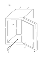
- FIG. 1 is a schematic diagram of a culture system according to an embodiment of the present disclosure
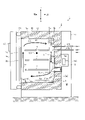
- FIG. Fig. 2 is a schematic vertical cross-section of the culture device according to an embodiment of the present disclosure as viewed from the right side
- Perspective view of LED module A perspective view of an LED module attached to a box.
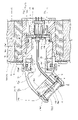
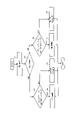
- Longitudinal cross-sectional view of the LED module attached to the box and its surroundings Longitudinal sectional view of the dummy module attached to the box and its surroundings Flowchart showing an operation example of the culture device
- the front, rear, left, and right of the culture device are defined as follows. That is, the side facing the user when in use (the side with the outer door 3a and the inner door 3b, which will be described later) is the front side, and the opposite side is the rear side. In addition, left and right are defined based on the case of viewing from the front to the back.
- FIG. 1 is a schematic diagram of a culture system according to one embodiment of the present disclosure.
- a culture system 200 shown in FIG. 1 includes a culture device 1 and an LED module 7 .
- the LED module 7 can be detachably attached to the culture device 1 from the inside of the culture device 1 (the culture space 20 side described later). Arrows in FIG. 1 indicate how the LED module 7 is attached to the culture device 1 and how the LED module 7 is removed from the culture device 1 .
- FIG. 2 is a schematic longitudinal section of the culture apparatus 1 viewed from the right side.
- the culture device 1 shown in FIG. 2 is a device for culturing cultures such as cells or microorganisms.
- This culture apparatus 1 includes a substantially box-shaped box body 2 having a culture space 20 formed therein and an opening 21 formed on the front surface, and an outer door 3a and an inner door 3b for opening and closing the opening 21 .
- the culture space 20 is vertically partitioned by a plurality of shelves 4 .
- a packing P1 is provided on the outer edge of the outer door 3a.
- the temperature, humidity, O 2 (oxygen) concentration, and CO 2 (carbon dioxide) concentration of the culture space 20 are maintained within appropriate ranges so as to create an atmosphere suitable for culturing the culture.
- the culture apparatus 1 has a temperature sensor 101 that detects the temperature of the culture space 20 .
- the box body 2 includes a substantially box-shaped inner box 2a in which the culture space 20 is formed, and a substantially box-shaped outer box 2b that covers the inner box 2a.
- the inner box 2a and the outer box 2b are made of metal plates.
- a heat insulating material 2c is arranged between the inner box 2a and the outer box 2b.
- the heat insulating material 2c is formed, for example, by combining plate-shaped heat insulating materials.
- a space (so-called air jacket) may be formed between the inner box 2a and the heat insulating material 2c.
- a vertically extending duct 5 is arranged on the back surface of the inner box 2a.
- a gas passage K is formed inside the duct 5 .
- a circulation fan 5c is arranged in the gas passage K. As shown in FIG.
- the circulation blower 5c By operating the circulation blower 5c, the air in the culture space 20 is sucked from the suction port 5a formed in the upper part of the duct 5, and the air flows into the culture space 20 from the outlet 5b provided in the lower part of the duct 5. blown out. This results in forced circulation of air as indicated by arrows A1, A2, A3 and A4.
- a humidification tray 6 for storing water W for humidification (hereinafter referred to as “humidification water W”) is installed.
- Adjustment gases (O 2 gas, N 2 gas, and CO 2 gas) for adjusting the O 2 gas concentration and the CO 2 gas concentration of the LED module 7 and the culture space 20 are supplied to the culture space 20 in the duct 5 .
- Gas supply devices 12a and 12b are installed for this purpose.
- the LED module 7 sterilizes the water W in the humidifying tray 6 and the air in the culture space 20 by emitting ultraviolet rays. The LED module 7 will be explained in detail later.
- each rear surface of the right side wall, the left side wall, the rear wall 2a2, the top wall and the bottom wall 2a1 of the inner box 2a (the surface on the side of the outer box 2b)
- temperature control that is, for controlling the temperature of the culture space 20.
- heaters 8 are installed respectively. In principle, the heater 8 is in a state of being energized and generating heat while the culture apparatus 1 is in operation.
- the output (heating power) of the heater 8 is controlled by the control device 100 .
- the circulation fan 5c, the gas supply devices 12a and 12b, and the heater 8 constitute an atmosphere adjusting device.
- the atmosphere adjustment device is a device that makes the inside of the box 2 (the culture space 20) an atmosphere suitable for culturing the culture. Needless to say, the atmosphere adjustment device may be configured by other elements in addition to the circulation fan 5c, the gas supply devices 12a and 12b, and the heater 8. FIG.
- the culture apparatus 1 receives commands to start and stop the culture apparatus 1, settings of the operation mode, and input of various setting values for the culture space 20 from the operation device 50 provided on the outer door 3a.
- Various set values for the culture space 20 include a set temperature, a set humidity, a set concentration of O 2 gas, a set concentration of CO 2 gas, and the like.
- the control device 100 controls components such as the atmosphere adjustment device and the LED module 7 based on the input from the operation device 50 .
- the operating device 50 has a display section for displaying the state of the culture device 1 .
- the operation modes of the culture apparatus 1 include at least a normal operation mode and a dry heat sterilization mode.
- the normal operation mode is a mode in which the atmosphere adjusting device is operated so that the inside of the box 2 (the culture space 20) has an atmosphere (for example, 37° C.) suitable for culturing the culture.
- the dry heat sterilization mode is a mode in which the atmosphere adjusting device is operated so as to dry heat sterilize the inside of the box 2 (the culture space 20). During the dry heat sterilization, the humidifying tray 6 is emptied, and the inside of the box 2 (the culture space 20) is maintained at 180° C., for example.
- the back surface and bottom surface of the outer box 2b of the box body 2 are covered with a cover 10.
- a space between the back surface of the outer casing 2b and the cover 10 forms a machine room M for arranging various devices.
- An electrical box 13 is provided in the machine room M.
- An interior 13a of the electrical equipment box 13 accommodates the control device 100 and other electrical components (not shown).
- the tip of the dew condensation member 11a is inserted into the culture space 20.
- This condensation member 11a is cooled by a Peltier element (not shown).
- condensed water is generated on the surface of the condensation member 11 a in the culture space 20 .
- the humidity in the culture space 20 can be lowered and controlled within an appropriate range. Condensed water generated on the surface of the condensation member 11a drips into the humidifying tray 6 from the tip of the condensation member 11a.
- FIG. 3 is a perspective view of the LED module 7.
- the LED module 7 includes an LED 76a (see FIG. 5) which will be described later, a metal cylinder 71 in which the LED 76a is housed, and a metal coupling 74. As shown in FIG.
- the tubular body 71 includes a distal tubular body 72 and a proximal tubular body 73 .
- a groove 73 a 1 extending parallel to the central axis of the proximal side cylinder is formed in the outer peripheral surface of the proximal side cylinder 73 .
- a through hole having a female screw is formed in the outer peripheral surface of the base end side cylindrical body 73, and a rotation restricting member 75 having a male screw shape is inserted into this through hole.
- the groove 73a1 and the rotation restricting member 75 will be described later in detail.
- the coupling 74 is a ring-shaped member surrounding the cylinder 71 and is rotatable relative to the cylinder 71 .
- FIG. 4 is a perspective view of the LED module 7 attached to the box 2, viewed from the culture space 20 side.
- the box 2 is formed with an insertion opening that opens at least on the culture space 20 side, and the LED module 7 is inserted into this insertion opening and fixed.
- a seal 15 is interposed between the engaged portion 14 and the rear wall 2a2.
- the engaged portion 14 has a male threaded portion, and the coupling 74 has a female threaded portion.
- the LED module 7 is fixed to the box body 2 by connecting the male screw portion and the female screw portion.
- connection between the coupling 74 and the engaged portion 14 can be realized by various known connection means such as a bayonet or a quick joint instead of screws.
- a bayonet is a connection means used, for example, in an interchangeable lens mounting structure of a single-lens reflex camera. That is, when applied to this embodiment, the engaged portion 14 has a plate-like portion in which a plurality of holes or grooves are formed, and the coupling 74 is formed with a plurality of engaging pieces. After the mating piece is inserted into the hole or groove, the coupling 74 rotates around the central axis of the coupling 74 and moves to the rear side of the plate-like portion, whereby the coupling 74 is connected to the engaged portion 14.
- FIG. 5 is a longitudinal sectional view of the LED module 7 attached to the box 2 and its surroundings.
- the insertion opening of the box 2 into which the LED module 7 is inserted is formed by a sleeve 16 made of resin.
- the sleeve 16 is arranged between the inner box 2a and the outer box 2b.
- the sleeve 16 is arranged between the inner case 2a and the outer case 2b, and is arranged in a cylindrical heat insulating material 2f that forms the opening of the box 2.
- a guide rail 16a is formed on the inner surface of the sleeve 16 so as to protrude inward.
- the insertion opening of the box 2 into which the LED module 7 is inserted is, of course, a space without the heat insulating material 2c. Therefore, this portion has low heat insulation and tends to become a heat path between the outside of the box 2 and the inside of the box 2 (the culture space 20).
- the sleeve 16 made of resin in the vicinity of the insertion opening into which the LED module 7 is inserted, between the inside and outside of the box 2 (specifically, between the inner box 2a and the outer box 2b, and It is possible to reduce the ease of heat transfer between the inner side and the outer side of the outer casing 2b.
- a device-side connector 2e is attached to the outer box 2b.
- the device-side connector 2 e is arranged in an insertion opening into which the LED module 7 is inserted, specifically in a sleeve 16 .
- the device-side connector 2e is located closer to the outer casing 2b than to the inner casing 2a, specifically, between the inner and outer end faces of the outer casing 2b and closer to the outer end face. In other words, the device-side connector 2 e is arranged at a position that is less susceptible to the temperature of the culture space 20 .
- the cylindrical body 71 that constitutes the LED module 7 includes a metal distal end side cylindrical body 72 and a metal proximal side cylindrical body 73 arranged on the proximal end side of the distal end side cylindrical body 72 .
- the base-end cylinder 73 includes a socket joint 73a and an end cap 73b.
- a through hole into which the aforementioned rotation restricting member 75 (see FIG. 2) is inserted is specifically formed in the socket joint 73a.
- the tip-side cylindrical body 72 is coaxial with the socket joint 73a, is inclined with respect to the connection portion 72a connected to the socket joint 73a, and is inclined with respect to the connection portion 72a. It has an elbow portion 72c that connects 72a and the LED housing portion 72b.
- the connection portion 72a and the elbow portion 72c are configured as one component, but the connection portion 72a and the elbow portion 72c may be configured as separate components.
- the LED housing portion 72b includes an LED mounting body 72b1 and a front cap 72b2.
- the LED mounting body 72b1 has a relatively thick solid portion, and a tip side substrate 76 to which an LED 76a is attached is arranged on the tip side of this solid portion.
- a heat conductive sheet 76b is arranged between the LED mounting body 72b1 and the tip side substrate 76. As shown in FIG. Therefore, the heat generated by the LED 76a is efficiently transferred to the relatively thick solid portion through the heat conductive sheet 76b.
- the relatively thick solid portion functions as a kind of heat sink.
- a male threaded portion is formed on the tip side of the LED mounting body 72b1, and a female threaded portion is formed on the inner surface side of the front cap 72b2.
- the LED mounting body 72b1 and the front cap 72b2 are connected.
- the window 72b3 and the O-ring R are sandwiched between the tip of the LED mounting body 72b1 and the tip side inner surface of the front cap 72b2, and between the proximal side inner surface of the front cap 72b2 and the LED mounting body 72b1. , an O-ring R is sandwiched.
- a male threaded portion is formed on the outer peripheral surface of the base end side of the LED mounting body 72b1, and a female threaded portion is formed on the inner peripheral surface of the elbow portion 72c. By connecting these screw portions, the elbow portion 72c is connected to the LED mounting body 72b1 and further to the LED housing portion 72b.
- a male threaded portion is formed on the outer peripheral surface of the connection portion 72a integrally formed with the elbow portion 72c, and a female threaded portion is formed on the inner peripheral surface of the socket joint 73a on the tip side.
- a rotation restricting member 75 is inserted into the socket joint 73a.
- a flat portion is formed on a part of the outer peripheral surface of the connecting portion 72a.
- the distal side cylinder 72 and the socket joint 73a are restricted from rotating relative to each other. can be set to a specific posture (the direction in which the LED storage portion 72b faces the humidifying tray 6). If the frictional force acting between the rotation restricting member 75 and the connection portion 72a can be made sufficiently large, no flat portion is formed on the outer peripheral surface of the connection portion 72a, and the entire outer peripheral surface of the connection portion 72a is It may be a cylindrical surface.
- the rotation restricting member 75 is in close contact with the socket joint 73a and the connecting portion 72a. Therefore, as will be described later, the LED 76 a generates heat, and the rotation restricting member 75 can transfer the heat transferred from the LED 76 a to the distal side tubular body 72 to the proximal side tubular body 73 . That is, by attaching the rotation restricting member 75, it is possible to increase the number of paths through which the heat generated by the LED 76a is released, and to dissipate the heat more efficiently.
- a male threaded portion is formed on the base end side of the socket joint 73a, and a female threaded portion is formed on the inner surface side of the end cap 73b.
- the socket joint 73a and the end cap 73b are connected.
- the proximal side substrate 77 and the seal 78 are sandwiched between the proximal side stepped portion of the socket joint 73a and the stepped portion of the end cap 73b.
- An O-ring R is sandwiched between
- a module-side connector 77d is attached to the proximal-side surface of the proximal-side substrate 77, that is, the surface facing the outside of the cylindrical body 71.
- the device-side connector 2e is connected to the module-side connector.
- the position and orientation of the module-side connector 77d are set so that the module-side connector 77d is fitted.
- Various parts electrically connected to the module-side connector 77d are attached to the surface of the base end-side substrate 77 on the front end side, that is, the surface facing the inside of the cylindrical body 71 .
- One of these components is a cable C that connects proximal board 77 and distal board 76 and provides power to LED 76a.
- a heater 77 a may be attached to the proximal substrate 77 .
- a metal foil pattern 77b may be formed on the surface of the proximal substrate 77 .
- An information holding device 77c is attached to the proximal substrate 77. As shown in FIG.
- the information holding device 77c may be any device capable of holding and outputting predetermined information, such as a semiconductor memory or a DIP switch.
- the information holding device 77c is preferably composed of a semiconductor memory capable of reading and writing information. Further, in this case, the control device 100 is configured to be able to store the time when the LED 76a is turned on in the information holding device 77c.
- the coupling 74 has a flange-like portion and a cylindrical portion connected to the outer peripheral end of the flange-like portion.
- the flange-like portion is located between the proximal end surface 72c1 of the elbow portion 72c and the flange portion 73a2 formed on the distal end side of the socket joint 73a.
- a female screw portion is formed on the inner surface of the cylindrical portion. This female threaded portion is connected to a male threaded portion formed so as to protrude toward the distal end side of the engaged portion 14 .
- the coupling 74 By rotating the coupling 74 after inserting the cylindrical body 71 into the sleeve 16, the female threaded portion of the coupling 74 and the male threaded portion of the engaged portion 14 can be connected. At this time, the O-ring R is sandwiched between the outer peripheral surface of the socket joint 73 a and the inner peripheral surface of the engaged portion 14 . Further, at this time, the flange portion 73a2 contacts the coupling 74 and the engaged portion 14 and is relatively strongly sandwiched between the coupling 74 and the engaged portion 14. As shown in FIG. That is, the cylindrical body 71 is in close contact with the coupling 74 and the engaged portion 14 . Therefore, as will be described later, the heat transmitted to the cylindrical body 71 is rapidly transmitted to the inner casing 2a via the engaged portion 14. As shown in FIG.
- the control device 100 acquires predetermined information from the information holding device 77c via the device-side connector 2e and the module-side connector 77d.
- the predetermined information is, for example, information indicating that the device attached to the box 2 is the LED module 7, or identification information with which at least one of the LED 76a and the LED module 7 can be identified.
- a specific example of the identification information is the model number identification number or the individual identification number of the LED 76a or the LED module 7, or the like.
- the control device 100 can control the LEDs 76a under appropriate conditions according to the type of the LEDs 76a included in the LED module 7 by acquiring the identification information. For example, it is possible to determine an appropriate supply current value and the length of time to supply the current based on the type of the LED 76a, and light the LED 76a with the determined supply current value and supply time. For example, in the case of the LED module 7 including the LED 76a that emits a high rated current and emits a high intensity of ultraviolet rays, the sterilization of the culture space 20 can be completed in a relatively short time. The supply time may be shortened.
- the control device 100 may control not only the length of time for lighting the LED 76a and the magnitude of the current supplied to the LED 76a, but also either one of them, based on the identification information. Needless to say.
- the identification information may be obtained based on a combination of voltage values generated at two predetermined pins among the plurality of pins of the module-side connector 77d.
- the voltage value generated at each pin can be changed by adjusting the resistance value of each pin. That is, instead of the information holding device 77c, which is a semiconductor memory or a DIP switch, for example, two resistors attached to two predetermined pins out of a plurality of pins of the module-side connector 77d function as the information holding device. You may
- the control device 100 may store in advance a combination of two voltage values and identification information in association with each other.
- the control device 100 can acquire identification information about the LED module 7 based on the voltage values acquired from the two predetermined pins and information stored in advance.
- the control device 100 may acquire the voltage values of two predetermined pins as analog values, A/D convert the acquired analog values, and acquire the identification information based on the two values after conversion.
- analog values By using analog values, many patterns of combinations of two voltage values can be created. In other words, simply by changing the resistance values of two pins, it is possible to create various kinds of identification information without increasing the number of pins of the module-side connector 77d.
- the LED module 7 can be manufactured at a lower cost than when using a semiconductor memory.
- the predetermined information may be the accumulated lighting time of the LED 76a.
- the control device 100 can control the LEDs 76a under appropriate conditions according to the state (for example, the degree of deterioration) of the LEDs 76a provided in the LED module 7 . For example, it is possible to determine at least one of the appropriate supply current value and the length of time to supply the current based on the state of the LED 76a, and to light the LED 76a at the determined supply current value and supply time.
- the controller 100 increases the current supplied to the LED 76a as the acquired cumulative lighting time increases. This can suppress the deterioration of the sterilization effect.
- control device 100 may store in advance a first coefficient that monotonically increases or increases stepwise as the cumulative lighting time of the LED 76a increases, in association with the cumulative lighting time of the LED 76a. In this case, the control device 100 determines the first coefficient based on the acquired accumulated lighting time, multiplies the determined first coefficient by the reference current value, and obtains the magnitude of the current supplied to the LED 76a. can be determined to As a result, the LED 76a can be lit with an appropriate current value according to the cumulative lighting time.
- the longer the acquired accumulated lighting time the longer the time for lighting the LED 76a instead of increasing the current supplied to the LED 76a. This can suppress the deterioration of the sterilization effect.
- control device 100 may store in advance a second coefficient that increases monotonically or in steps as the cumulative lighting time of the LED 76a increases, in association with the cumulative lighting time of the LED 76a.
- the control device 100 determines the second coefficient based on the acquired cumulative lighting time, multiplies the determined second coefficient by the reference length of time, and uses the obtained value as the length of time for lighting the LED 76a. can be determined to As a result, the LED 76a can be lit for an appropriate lighting time according to the accumulated lighting time.
- the LED 76a generates heat when emitting ultraviolet rays, and is relatively weak against heat.
- the higher the temperature inside the box 2 that is, the temperature of the culture space 20
- the supply current value is decreased, the intensity of the ultraviolet rays is decreased and the sterilization effect is decreased.
- the control device 100 may reduce the current supplied to the LED 76a and lengthen the lighting time of the LED 76a as the temperature inside the box 2 increases. By doing so, the sterilization effect can be maintained, and the culture space 20 can be reliably sterilized while slowing down the deterioration of the LEDs 76a.
- the control device 100 acquires the temperature inside the box 2 from the temperature sensor 101 . Note that the control device 100 may acquire the set temperature of the culture space 20 input to the operation device 50 as the temperature inside the box 2 .
- control device 100 may store in advance a third coefficient that monotonously decreases or decreases stepwise as the temperature inside the box 2 rises, in association with the temperature inside the box 2 .
- the control device 100 determines the third coefficient based on the obtained internal temperature of the box 2, multiplies the determined third coefficient by the reference current value, and supplies the obtained value to the LED 76a. can be determined by the magnitude of the current. Therefore, it is possible to light the LED 76 a with an appropriate current value according to the temperature inside the box 2 .
- control device 100 may store in advance a plurality of sets of the third coefficient and the temperature inside the box 2, and may select a set to be used for controlling the LED 76a based on the acquired identification information. .
- the control device 100 may store in advance a plurality of sets of the third coefficient and the temperature inside the box 2, and may select a set to be used for controlling the LED 76a based on the acquired identification information. .
- the control device 100 may store in advance a plurality of sets of the third coefficient and the temperature inside the box 2, and may select a set to be used for controlling the LED 76a based on the acquired identification information.
- control device 100 may store in advance a fourth coefficient that increases monotonically or stepwise with the temperature inside the box 2 in association with the temperature inside the box 2 .
- the control device 100 determines the fourth coefficient based on the acquired internal temperature of the box 2 so as to maintain the sterilization effect in response to the decrease in the supply current value, and the determined fourth coefficient
- the reference length of time can be multiplied by a factor and the resulting value determined to be the length of time the LED 76a is to be illuminated. Thereby, the LED 76a can be lit for an appropriate lighting time according to the temperature inside the box 2 so as to maintain the sterilization effect.
- control device 100 stores in advance a plurality of sets of the fourth coefficient and the temperature inside the box 2 of the LED 76a, and selects a set to be used for controlling the LED 76a based on the acquired identification information. good. By selecting an appropriate set based on the type of the LEDs 76a, it is possible to appropriately prevent the temperature of the LEDs 76a from increasing and premature deterioration of the LEDs 76a while maintaining the sterilization effect.
- the LED 76a When the LED 76a emits ultraviolet rays, it generates heat at the same time. Since the LED 76a is relatively heat-sensitive, it is necessary to quickly dissipate the heat emitted from the LED 76a to prevent the LED 76a from becoming hot.
- the LED module 7 includes the metal cylinder 71 as described above. Therefore, the heat generated by the LED 76a is easily transferred to the cylindrical body 71. As shown in FIG. Further, the cylinder 71 is in contact with the metal engaged portion 14, and the engaged portion 14 is in contact with the metal inner box 2a. Therefore, the cylindrical body 71 and the coupling 74 release the heat generated by the LED 76 a to the engaged portion 14 . The heat transmitted to the engaged portion 14 is quickly transmitted to the metal inner box. In other words, the heat transmitted from the LED 76a to the cylindrical body 71 is transmitted to the inner casing 2a via the engaged portion 14. As shown in FIG.
- the heat generated by the LED 76a is efficiently dissipated through the heat transfer route made of the metal member, and the LED 76a can be prevented from becoming hot.
- the resin sleeve 16 which does not easily conduct heat, is arranged between the inner box 2a and the outer box 2b, it is possible to prevent the heat generated by the LED 76a from being transferred to the device-side connector 2e. can.
- the LED 76a may malfunction or deteriorate due to the heat generated by itself in the environment of the temperature of the culture space 20 (for example, 37° C.) when the normal operation mode is performed. can be prevented.
- the LED module 7 is removed from the box 2 when the culture apparatus 1 is operated in the dry heat sterilization mode.
- the dummy module 9 shown in FIG. FIG. 6 is a longitudinal sectional view of the dummy module 9 attached to the box 2 and its surroundings.
- the dummy module 9 includes a dummy main body 91 and a handle 92 formed on the distal end side of the dummy main body 91 .
- the dummy module 9 can be attached to the box body 2 by holding the handle 92 and inserting it into the insertion opening.
- a groove 91a into which the guide rail 16a can be inserted is formed in the side surface of the dummy main body 91. As shown in FIG.
- a dummy substrate 93 may be fixed to the base end side of the dummy module 9 .
- a dummy connector 93b is attached to the base end side surface of the dummy substrate 93, and an information holding device 93a electrically connected to the dummy connector 93b is attached to the tip side surface of the dummy substrate 93. good too.
- the controller 100 connects the device-side connector 2e and the dummy connector 93b by connecting the dummy connector 93b to the device-side connector 2e. Predetermined information is acquired from the information holding device 93a via the information holding device 93a.
- the predetermined information is, for example, information indicating that the device attached to the box 2 is the dummy module 9 .
- the control device 100 can recognize that the dummy module 9 is attached.
- the control device 100 operates the dry heat sterilization mode while protecting the device-side connector 2e from heat with the dummy module 9. It can be done in a culture device.
- the device-side connector 2e is arranged at a position closer to the outer casing 2b than the inner casing 2a. Therefore, the device-side connector 2e is less likely to be affected by the temperature of the culture space 20, particularly by the high temperature when dry heat sterilization is performed. Moreover, the space into which the dummy main body 91 is inserted can be increased, in other words, the volume of the dummy main body 91 inserted into the insertion port can be increased. Therefore, the heat insulation performance of the dummy module 9, that is, the effect of protecting the device-side connector 2e from heat can be increased.
- FIG. 7 is a flow chart showing an operation example of the culture device 1 according to the present disclosure. An operation example will be described below with reference to FIG.
- the control device 100 accepts a driving instruction (S1). Upon receiving the driving instruction, the control device 100 confirms the content of the instruction (S2). If the content of the instruction is an instruction for cultivation operation (cultivation in S2), the control device 100 confirms whether or not the LED module 7 is attached to the box 2 (S3). When the LED module 7 is attached (YES in S3), the control device 100 activates the atmosphere adjustment device (the circulation fan 5c, the gas supply devices 12a and 12b, the heater 8, etc.) to operate the culture device 1. is operated in normal operation mode (S4).
- the atmosphere adjustment device the circulation fan 5c, the gas supply devices 12a and 12b, the heater 8, etc.
- the control device 100 acquires predetermined information from the information holding device 77c, and controls the LED 76a based on the acquired predetermined information. Therefore, an appropriate current value and lighting time can be set based on the type or state of the LED module 7 or the LED 76a. Also, at this time, the temperature of the culture space 20 may be detected by the temperature sensor 101, and the current value to be supplied to the LEDs 76a and the length of time during which the current is supplied to the LEDs 76a may be determined based on the detected temperature.
- the control device 100 acquires the accumulated lighting time from the information holding device 77c
- the control device 100 calculates the latest accumulated lighting time by adding the length of time during which the LED 76a is lit after that, and stores it in the information holding device 77c. You may let Further, when the calculated cumulative lighting time exceeds a predetermined threshold value, the operation device 50 may display a display prompting replacement of the LED module 7 .
- This threshold is, for example, the length of life for which the LED 76a functions effectively, or the length obtained by subtracting a predetermined time from the life. By performing such a display, the LED module 7 can be replaced at an appropriate timing, and the culture space 20 can be properly sterilized at all times.
- the control device 100 displays a message prompting the user to attach the LED module 7 on the display section of the operation device 50 (S5). Therefore, it is possible to prevent the operation of culturing the culture in a state in which the LED module 7 is not attached, that is, in a state in which sterilization by ultraviolet irradiation cannot be performed.
- the control device 100 confirms whether or not the dummy module 9 is attached to the box 2 (S6). . If the dummy module 9 is attached (YES in S6), the control device 100 operates the atmosphere adjustment device to operate the culture device 1 in the dry heat operation mode (S7).
- the control device 100 displays a display prompting the installation of the dummy module 9 on the display section of the operation device 50 (S8). Therefore, it is possible to prevent the dry heat operation from being performed in a state in which the dummy module 9 is not attached, that is, in a state in which there is nothing blocking the space between the device-side connector 2e and the culture space 20.
- the LED module 7 according to the present disclosure includes the metal cylindrical body 71, heat is easily conducted. Moreover, the insertion opening of the box 2 into which the LED module 7 is inserted has low heat insulation. Therefore, when the outside air temperature is low, the temperature on the tip side of the LED module 7 may be lowered, and the temperature of the culture space 20 may be lowered. In order to prevent such a temperature drop, the LED module 7 according to this embodiment can be provided with a heater 77a on the surface of the proximal substrate 77. As shown in FIG. By operating the heater 77a by the control device 100, it is possible to prevent the temperature of the culture space 20 from dropping when the ambient temperature of the culture device 1, that is, the outside air temperature is low.
- the LED module 7 can have a metal foil pattern 77b on the surface of the proximal substrate 77 .
- the metal foil pattern 77b By providing the metal foil pattern 77b, the heat generated by the heater 77a can be efficiently transferred to the cylindrical body 71.
- the metal foil pattern 77b may be in contact with the cylindrical body 71, specifically the base end side cylindrical body 73, more specifically the inner peripheral surface of the socket joint 73a. Heat can be transferred more efficiently by making contact.
- the heater 77a may be attached to a place other than the surface of the proximal substrate 77, for example, the inner surface of the socket joint 73a.
- the culture device 1 according to the present disclosure also includes a resin sleeve 16 arranged between the inner box 2a and the outer box 2b. Therefore, it is possible to suppress the heat transfer between the inside and the outside of the box body, that is, to suppress the degree of decrease in the temperature of the culture space 20 when the outside air temperature is low.
- the LED 76a emits heat. Therefore, when the LED 76a is turned off, the temperature of the culture space 20 is lowered. Therefore, by activating the heater 77a when the LED 76a is turned off, it is possible to prevent the temperature of the culture space 20 from decreasing. In this case, the amount of heat given to the inner box 2a by the LED 76a when the LED 76a is operating and the amount of heat given by the heater 77a to the inner box 2a when the heater 77a is operating are substantially equal. , the power supplied to the heater 77a may be controlled. By controlling the electric power in such a manner, it is possible to prevent the temperature change of the culture space 20 due to the operation of the LED 76a and the heater 77a.
- the temperature on the tip side of the LED module 7 may drop, and the temperature of the culture space 20 may drop.
- this characteristic may be used to generate condensed water on the tip side surface of the LED module 7 when the outside air temperature is lower than the dew point inside the box 2 , that is, the culture space 20 .
- the LED module 7 may function as a member for adjusting the humidity in the culture space 20 instead of the condensation member 11a.
- the positions of the LED module 7 and the humidifying tray 6 are set so that the condensed water generated on the tip side surface of the LED module 7 falls into the humidifying tray 6 .
- the present disclosure is suitably used as an LED module and culture system.
Landscapes
- Health & Medical Sciences (AREA)
- Life Sciences & Earth Sciences (AREA)
- Chemical & Material Sciences (AREA)
- Engineering & Computer Science (AREA)
- Zoology (AREA)
- Organic Chemistry (AREA)
- Bioinformatics & Cheminformatics (AREA)
- Wood Science & Technology (AREA)
- General Health & Medical Sciences (AREA)
- Genetics & Genomics (AREA)
- Biotechnology (AREA)
- Biochemistry (AREA)
- Sustainable Development (AREA)
- General Engineering & Computer Science (AREA)
- Microbiology (AREA)
- Biomedical Technology (AREA)
- Public Health (AREA)
- Epidemiology (AREA)
- Animal Behavior & Ethology (AREA)
- Veterinary Medicine (AREA)
- Analytical Chemistry (AREA)
- Physics & Mathematics (AREA)
- Thermal Sciences (AREA)
- Molecular Biology (AREA)
- Apparatus Associated With Microorganisms And Enzymes (AREA)
Priority Applications (4)
| Application Number | Priority Date | Filing Date | Title |
|---|---|---|---|
| JP2023535164A JP7668881B2 (ja) | 2021-07-15 | 2022-05-25 | Ledモジュールおよび培養装置 |
| CN202280040144.2A CN117460816A (zh) | 2021-07-15 | 2022-05-25 | Led模块及培养装置 |
| EP22841809.1A EP4335915A4 (en) | 2021-07-15 | 2022-05-25 | LED module and culture device |
| US18/408,848 US20240141267A1 (en) | 2021-07-15 | 2024-01-10 | Led module and culture apparatus |
Applications Claiming Priority (2)
| Application Number | Priority Date | Filing Date | Title |
|---|---|---|---|
| JP2021117005 | 2021-07-15 | ||
| JP2021-117005 | 2021-07-15 |
Related Child Applications (1)
| Application Number | Title | Priority Date | Filing Date |
|---|---|---|---|
| US18/408,848 Continuation US20240141267A1 (en) | 2021-07-15 | 2024-01-10 | Led module and culture apparatus |
Publications (1)
| Publication Number | Publication Date |
|---|---|
| WO2023286462A1 true WO2023286462A1 (ja) | 2023-01-19 |
Family
ID=84919930
Family Applications (1)
| Application Number | Title | Priority Date | Filing Date |
|---|---|---|---|
| PCT/JP2022/021426 Ceased WO2023286462A1 (ja) | 2021-07-15 | 2022-05-25 | Ledモジュールおよび培養装置 |
Country Status (5)
| Country | Link |
|---|---|
| US (1) | US20240141267A1 (https=) |
| EP (1) | EP4335915A4 (https=) |
| JP (1) | JP7668881B2 (https=) |
| CN (1) | CN117460816A (https=) |
| WO (1) | WO2023286462A1 (https=) |
Families Citing this family (1)
| Publication number | Priority date | Publication date | Assignee | Title |
|---|---|---|---|---|
| DE112023004292T5 (de) * | 2022-10-07 | 2025-08-14 | Microchip Technology Incorporated | Authentisierung und identifizierung von produkten |
Citations (6)
| Publication number | Priority date | Publication date | Assignee | Title |
|---|---|---|---|---|
| WO2010150782A1 (ja) * | 2009-06-26 | 2010-12-29 | ノーリツ鋼機株式会社 | 印刷装置 |
| WO2011031167A1 (en) * | 2009-09-08 | 2011-03-17 | Mondiale Technologies Limited | Heating and sterilisation apparatus, incubators and incubator systems |
| JP2015026901A (ja) * | 2013-07-24 | 2015-02-05 | 株式会社東芝 | リコンフィギュラブル論理回路 |
| WO2018061934A1 (ja) * | 2016-09-27 | 2018-04-05 | 日機装株式会社 | 紫外光照射装置 |
| CN212116492U (zh) * | 2020-01-06 | 2020-12-11 | 华南农业大学 | 一种食用菌温控培养箱 |
| JP2021117005A (ja) | 2020-01-22 | 2021-08-10 | 株式会社島津製作所 | 水素濃度測定装置及び水素濃度測定方法 |
Family Cites Families (4)
| Publication number | Priority date | Publication date | Assignee | Title |
|---|---|---|---|---|
| WO2010024163A1 (ja) * | 2008-08-26 | 2010-03-04 | 三洋電機株式会社 | 培養装置 |
| WO2013047213A1 (ja) | 2011-09-27 | 2013-04-04 | 日本電気株式会社 | 不揮発抵抗ネットワーク集合体、および、それを用いた障害耐性を高めた不揮発論理ゲート |
| KR101852410B1 (ko) * | 2017-06-19 | 2018-04-27 | 엘지전자 주식회사 | 피부 관리 기기 |
| US11735599B2 (en) | 2018-03-12 | 2023-08-22 | Rohm Co., Ltd. | Semiconductor device and semiconductor device identification method |
-
2022
- 2022-05-25 JP JP2023535164A patent/JP7668881B2/ja active Active
- 2022-05-25 WO PCT/JP2022/021426 patent/WO2023286462A1/ja not_active Ceased
- 2022-05-25 EP EP22841809.1A patent/EP4335915A4/en active Pending
- 2022-05-25 CN CN202280040144.2A patent/CN117460816A/zh active Pending
-
2024
- 2024-01-10 US US18/408,848 patent/US20240141267A1/en active Pending
Patent Citations (6)
| Publication number | Priority date | Publication date | Assignee | Title |
|---|---|---|---|---|
| WO2010150782A1 (ja) * | 2009-06-26 | 2010-12-29 | ノーリツ鋼機株式会社 | 印刷装置 |
| WO2011031167A1 (en) * | 2009-09-08 | 2011-03-17 | Mondiale Technologies Limited | Heating and sterilisation apparatus, incubators and incubator systems |
| JP2015026901A (ja) * | 2013-07-24 | 2015-02-05 | 株式会社東芝 | リコンフィギュラブル論理回路 |
| WO2018061934A1 (ja) * | 2016-09-27 | 2018-04-05 | 日機装株式会社 | 紫外光照射装置 |
| CN212116492U (zh) * | 2020-01-06 | 2020-12-11 | 华南农业大学 | 一种食用菌温控培养箱 |
| JP2021117005A (ja) | 2020-01-22 | 2021-08-10 | 株式会社島津製作所 | 水素濃度測定装置及び水素濃度測定方法 |
Non-Patent Citations (1)
| Title |
|---|
| See also references of EP4335915A4 |
Also Published As
| Publication number | Publication date |
|---|---|
| EP4335915A4 (en) | 2025-04-16 |
| CN117460816A (zh) | 2024-01-26 |
| EP4335915A1 (en) | 2024-03-13 |
| JP7668881B2 (ja) | 2025-04-25 |
| JPWO2023286462A1 (https=) | 2023-01-19 |
| US20240141267A1 (en) | 2024-05-02 |
Similar Documents
| Publication | Publication Date | Title |
|---|---|---|
| CA2709084C (en) | Volatile material diffuser and method of preventing undesirable mixing of volatile materials | |
| US8765073B1 (en) | Wall socket aroma diffuser using aroma capsule | |
| EP2319911B1 (en) | Culture apparatus | |
| KR101740325B1 (ko) | 구강스캐너 거치 장치 및 이를 포함하는 구강스캐너 시스템 | |
| KR101539985B1 (ko) | 조명장치 | |
| WO2023286462A1 (ja) | Ledモジュールおよび培養装置 | |
| US20190336634A1 (en) | Housing apparatus | |
| KR200347100Y1 (ko) | 살균, 탈취 및 건조 수단을 구비한 신발수납장 | |
| JP6666768B2 (ja) | 培養装置 | |
| JP7719185B2 (ja) | 培養装置 | |
| WO2023286461A1 (ja) | Ledモジュールおよび培養装置 | |
| ES2908851T3 (es) | Dispositivo de medición de nivel para un dispositivo de gabinete de laboratorio | |
| JP5341434B2 (ja) | 培養装置 | |
| JP2011004943A (ja) | 歯ブラシ殺菌装置 | |
| JP2009153899A5 (https=) | ||
| JP7793037B2 (ja) | 培養装置及び培養システム | |
| KR101798913B1 (ko) | 살균 기능을 가진 조명 장치 | |
| CN214469964U (zh) | 压力气枪及气源装置 | |
| JP6142443B2 (ja) | 培養システム、および培養システムの使用方法 | |
| JPH05168583A (ja) | 硬性内視鏡システム |
Legal Events
| Date | Code | Title | Description |
|---|---|---|---|
| 121 | Ep: the epo has been informed by wipo that ep was designated in this application |
Ref document number: 22841809 Country of ref document: EP Kind code of ref document: A1 |
|
| WWE | Wipo information: entry into national phase |
Ref document number: 2023535164 Country of ref document: JP |
|
| WWE | Wipo information: entry into national phase |
Ref document number: 202280040144.2 Country of ref document: CN |
|
| WWE | Wipo information: entry into national phase |
Ref document number: 2022841809 Country of ref document: EP |
|
| ENP | Entry into the national phase |
Ref document number: 2022841809 Country of ref document: EP Effective date: 20231208 |
|
| NENP | Non-entry into the national phase |
Ref country code: DE |