WO2023286440A1 - 連続焼鈍装置及び連続溶融亜鉛めっき装置、並びに鋼板の製造方法 - Google Patents
連続焼鈍装置及び連続溶融亜鉛めっき装置、並びに鋼板の製造方法 Download PDFInfo
- Publication number
- WO2023286440A1 WO2023286440A1 PCT/JP2022/020579 JP2022020579W WO2023286440A1 WO 2023286440 A1 WO2023286440 A1 WO 2023286440A1 JP 2022020579 W JP2022020579 W JP 2022020579W WO 2023286440 A1 WO2023286440 A1 WO 2023286440A1
- Authority
- WO
- WIPO (PCT)
- Prior art keywords
- steel sheet
- cold
- rolled steel
- less
- vibration
- Prior art date
- Legal status (The legal status is an assumption and is not a legal conclusion. Google has not performed a legal analysis and makes no representation as to the accuracy of the status listed.)
- Ceased
Links
Images



Classifications
-
- C—CHEMISTRY; METALLURGY
- C21—METALLURGY OF IRON
- C21D—MODIFYING THE PHYSICAL STRUCTURE OF FERROUS METALS; GENERAL DEVICES FOR HEAT TREATMENT OF FERROUS OR NON-FERROUS METALS OR ALLOYS; MAKING METAL MALLEABLE, e.g. BY DECARBURISATION OR TEMPERING
- C21D9/00—Heat treatment, e.g. annealing, hardening, quenching or tempering, adapted for particular articles; Furnaces therefor
- C21D9/005—Furnaces in which the charge is moving up or down
-
- C—CHEMISTRY; METALLURGY
- C22—METALLURGY; FERROUS OR NON-FERROUS ALLOYS; TREATMENT OF ALLOYS OR NON-FERROUS METALS
- C22C—ALLOYS
- C22C38/00—Ferrous alloys, e.g. steel alloys
- C22C38/18—Ferrous alloys, e.g. steel alloys containing chromium
- C22C38/40—Ferrous alloys, e.g. steel alloys containing chromium with nickel
- C22C38/58—Ferrous alloys, e.g. steel alloys containing chromium with nickel with more than 1.5% by weight of manganese
-
- C—CHEMISTRY; METALLURGY
- C21—METALLURGY OF IRON
- C21D—MODIFYING THE PHYSICAL STRUCTURE OF FERROUS METALS; GENERAL DEVICES FOR HEAT TREATMENT OF FERROUS OR NON-FERROUS METALS OR ALLOYS; MAKING METAL MALLEABLE, e.g. BY DECARBURISATION OR TEMPERING
- C21D1/00—General methods or devices for heat treatment, e.g. annealing, hardening, quenching or tempering
- C21D1/04—General methods or devices for heat treatment, e.g. annealing, hardening, quenching or tempering with simultaneous application of supersonic waves, magnetic or electric fields
-
- C—CHEMISTRY; METALLURGY
- C21—METALLURGY OF IRON
- C21D—MODIFYING THE PHYSICAL STRUCTURE OF FERROUS METALS; GENERAL DEVICES FOR HEAT TREATMENT OF FERROUS OR NON-FERROUS METALS OR ALLOYS; MAKING METAL MALLEABLE, e.g. BY DECARBURISATION OR TEMPERING
- C21D1/00—General methods or devices for heat treatment, e.g. annealing, hardening, quenching or tempering
- C21D1/26—Methods of annealing
-
- C—CHEMISTRY; METALLURGY
- C21—METALLURGY OF IRON
- C21D—MODIFYING THE PHYSICAL STRUCTURE OF FERROUS METALS; GENERAL DEVICES FOR HEAT TREATMENT OF FERROUS OR NON-FERROUS METALS OR ALLOYS; MAKING METAL MALLEABLE, e.g. BY DECARBURISATION OR TEMPERING
- C21D10/00—Modifying the physical properties by methods other than heat treatment or deformation
-
- C—CHEMISTRY; METALLURGY
- C21—METALLURGY OF IRON
- C21D—MODIFYING THE PHYSICAL STRUCTURE OF FERROUS METALS; GENERAL DEVICES FOR HEAT TREATMENT OF FERROUS OR NON-FERROUS METALS OR ALLOYS; MAKING METAL MALLEABLE, e.g. BY DECARBURISATION OR TEMPERING
- C21D3/00—Diffusion processes for extraction of non-metals; Furnaces therefor
- C21D3/02—Extraction of non-metals
- C21D3/06—Extraction of hydrogen
-
- C—CHEMISTRY; METALLURGY
- C21—METALLURGY OF IRON
- C21D—MODIFYING THE PHYSICAL STRUCTURE OF FERROUS METALS; GENERAL DEVICES FOR HEAT TREATMENT OF FERROUS OR NON-FERROUS METALS OR ALLOYS; MAKING METAL MALLEABLE, e.g. BY DECARBURISATION OR TEMPERING
- C21D9/00—Heat treatment, e.g. annealing, hardening, quenching or tempering, adapted for particular articles; Furnaces therefor
- C21D9/46—Heat treatment, e.g. annealing, hardening, quenching or tempering, adapted for particular articles; Furnaces therefor for sheet metals
-
- C—CHEMISTRY; METALLURGY
- C21—METALLURGY OF IRON
- C21D—MODIFYING THE PHYSICAL STRUCTURE OF FERROUS METALS; GENERAL DEVICES FOR HEAT TREATMENT OF FERROUS OR NON-FERROUS METALS OR ALLOYS; MAKING METAL MALLEABLE, e.g. BY DECARBURISATION OR TEMPERING
- C21D9/00—Heat treatment, e.g. annealing, hardening, quenching or tempering, adapted for particular articles; Furnaces therefor
- C21D9/52—Heat treatment, e.g. annealing, hardening, quenching or tempering, adapted for particular articles; Furnaces therefor for wires; for strips ; for rods of unlimited length
- C21D9/54—Furnaces for treating strips or wire
- C21D9/56—Continuous furnaces for strip or wire
-
- C—CHEMISTRY; METALLURGY
- C21—METALLURGY OF IRON
- C21D—MODIFYING THE PHYSICAL STRUCTURE OF FERROUS METALS; GENERAL DEVICES FOR HEAT TREATMENT OF FERROUS OR NON-FERROUS METALS OR ALLOYS; MAKING METAL MALLEABLE, e.g. BY DECARBURISATION OR TEMPERING
- C21D9/00—Heat treatment, e.g. annealing, hardening, quenching or tempering, adapted for particular articles; Furnaces therefor
- C21D9/52—Heat treatment, e.g. annealing, hardening, quenching or tempering, adapted for particular articles; Furnaces therefor for wires; for strips ; for rods of unlimited length
- C21D9/54—Furnaces for treating strips or wire
- C21D9/56—Continuous furnaces for strip or wire
- C21D9/562—Details
-
- C—CHEMISTRY; METALLURGY
- C22—METALLURGY; FERROUS OR NON-FERROUS ALLOYS; TREATMENT OF ALLOYS OR NON-FERROUS METALS
- C22C—ALLOYS
- C22C38/00—Ferrous alloys, e.g. steel alloys
- C22C38/001—Ferrous alloys, e.g. steel alloys containing N
-
- C—CHEMISTRY; METALLURGY
- C22—METALLURGY; FERROUS OR NON-FERROUS ALLOYS; TREATMENT OF ALLOYS OR NON-FERROUS METALS
- C22C—ALLOYS
- C22C38/00—Ferrous alloys, e.g. steel alloys
- C22C38/002—Ferrous alloys, e.g. steel alloys containing In, Mg, or other elements not provided for in one single group C22C38/001 - C22C38/60
-
- C—CHEMISTRY; METALLURGY
- C22—METALLURGY; FERROUS OR NON-FERROUS ALLOYS; TREATMENT OF ALLOYS OR NON-FERROUS METALS
- C22C—ALLOYS
- C22C38/00—Ferrous alloys, e.g. steel alloys
- C22C38/005—Ferrous alloys, e.g. steel alloys containing rare earths, i.e. Sc, Y, Lanthanides
-
- C—CHEMISTRY; METALLURGY
- C22—METALLURGY; FERROUS OR NON-FERROUS ALLOYS; TREATMENT OF ALLOYS OR NON-FERROUS METALS
- C22C—ALLOYS
- C22C38/00—Ferrous alloys, e.g. steel alloys
- C22C38/008—Ferrous alloys, e.g. steel alloys containing tin
-
- C—CHEMISTRY; METALLURGY
- C22—METALLURGY; FERROUS OR NON-FERROUS ALLOYS; TREATMENT OF ALLOYS OR NON-FERROUS METALS
- C22C—ALLOYS
- C22C38/00—Ferrous alloys, e.g. steel alloys
- C22C38/02—Ferrous alloys, e.g. steel alloys containing silicon
-
- C—CHEMISTRY; METALLURGY
- C22—METALLURGY; FERROUS OR NON-FERROUS ALLOYS; TREATMENT OF ALLOYS OR NON-FERROUS METALS
- C22C—ALLOYS
- C22C38/00—Ferrous alloys, e.g. steel alloys
- C22C38/04—Ferrous alloys, e.g. steel alloys containing manganese
-
- C—CHEMISTRY; METALLURGY
- C22—METALLURGY; FERROUS OR NON-FERROUS ALLOYS; TREATMENT OF ALLOYS OR NON-FERROUS METALS
- C22C—ALLOYS
- C22C38/00—Ferrous alloys, e.g. steel alloys
- C22C38/06—Ferrous alloys, e.g. steel alloys containing aluminium
-
- C—CHEMISTRY; METALLURGY
- C22—METALLURGY; FERROUS OR NON-FERROUS ALLOYS; TREATMENT OF ALLOYS OR NON-FERROUS METALS
- C22C—ALLOYS
- C22C38/00—Ferrous alloys, e.g. steel alloys
- C22C38/08—Ferrous alloys, e.g. steel alloys containing nickel
-
- C—CHEMISTRY; METALLURGY
- C22—METALLURGY; FERROUS OR NON-FERROUS ALLOYS; TREATMENT OF ALLOYS OR NON-FERROUS METALS
- C22C—ALLOYS
- C22C38/00—Ferrous alloys, e.g. steel alloys
- C22C38/12—Ferrous alloys, e.g. steel alloys containing tungsten, tantalum, molybdenum, vanadium, or niobium
-
- C—CHEMISTRY; METALLURGY
- C22—METALLURGY; FERROUS OR NON-FERROUS ALLOYS; TREATMENT OF ALLOYS OR NON-FERROUS METALS
- C22C—ALLOYS
- C22C38/00—Ferrous alloys, e.g. steel alloys
- C22C38/14—Ferrous alloys, e.g. steel alloys containing titanium or zirconium
-
- C—CHEMISTRY; METALLURGY
- C22—METALLURGY; FERROUS OR NON-FERROUS ALLOYS; TREATMENT OF ALLOYS OR NON-FERROUS METALS
- C22C—ALLOYS
- C22C38/00—Ferrous alloys, e.g. steel alloys
- C22C38/16—Ferrous alloys, e.g. steel alloys containing copper
-
- C—CHEMISTRY; METALLURGY
- C22—METALLURGY; FERROUS OR NON-FERROUS ALLOYS; TREATMENT OF ALLOYS OR NON-FERROUS METALS
- C22C—ALLOYS
- C22C38/00—Ferrous alloys, e.g. steel alloys
- C22C38/18—Ferrous alloys, e.g. steel alloys containing chromium
- C22C38/32—Ferrous alloys, e.g. steel alloys containing chromium with boron
-
- C—CHEMISTRY; METALLURGY
- C22—METALLURGY; FERROUS OR NON-FERROUS ALLOYS; TREATMENT OF ALLOYS OR NON-FERROUS METALS
- C22C—ALLOYS
- C22C38/00—Ferrous alloys, e.g. steel alloys
- C22C38/18—Ferrous alloys, e.g. steel alloys containing chromium
- C22C38/38—Ferrous alloys, e.g. steel alloys containing chromium with more than 1.5% by weight of manganese
-
- C—CHEMISTRY; METALLURGY
- C22—METALLURGY; FERROUS OR NON-FERROUS ALLOYS; TREATMENT OF ALLOYS OR NON-FERROUS METALS
- C22C—ALLOYS
- C22C38/00—Ferrous alloys, e.g. steel alloys
- C22C38/18—Ferrous alloys, e.g. steel alloys containing chromium
- C22C38/40—Ferrous alloys, e.g. steel alloys containing chromium with nickel
- C22C38/42—Ferrous alloys, e.g. steel alloys containing chromium with nickel with copper
-
- C—CHEMISTRY; METALLURGY
- C22—METALLURGY; FERROUS OR NON-FERROUS ALLOYS; TREATMENT OF ALLOYS OR NON-FERROUS METALS
- C22C—ALLOYS
- C22C38/00—Ferrous alloys, e.g. steel alloys
- C22C38/18—Ferrous alloys, e.g. steel alloys containing chromium
- C22C38/40—Ferrous alloys, e.g. steel alloys containing chromium with nickel
- C22C38/44—Ferrous alloys, e.g. steel alloys containing chromium with nickel with molybdenum or tungsten
-
- C—CHEMISTRY; METALLURGY
- C22—METALLURGY; FERROUS OR NON-FERROUS ALLOYS; TREATMENT OF ALLOYS OR NON-FERROUS METALS
- C22C—ALLOYS
- C22C38/00—Ferrous alloys, e.g. steel alloys
- C22C38/18—Ferrous alloys, e.g. steel alloys containing chromium
- C22C38/40—Ferrous alloys, e.g. steel alloys containing chromium with nickel
- C22C38/46—Ferrous alloys, e.g. steel alloys containing chromium with nickel with vanadium
-
- C—CHEMISTRY; METALLURGY
- C22—METALLURGY; FERROUS OR NON-FERROUS ALLOYS; TREATMENT OF ALLOYS OR NON-FERROUS METALS
- C22C—ALLOYS
- C22C38/00—Ferrous alloys, e.g. steel alloys
- C22C38/18—Ferrous alloys, e.g. steel alloys containing chromium
- C22C38/40—Ferrous alloys, e.g. steel alloys containing chromium with nickel
- C22C38/48—Ferrous alloys, e.g. steel alloys containing chromium with nickel with niobium or tantalum
-
- C—CHEMISTRY; METALLURGY
- C22—METALLURGY; FERROUS OR NON-FERROUS ALLOYS; TREATMENT OF ALLOYS OR NON-FERROUS METALS
- C22C—ALLOYS
- C22C38/00—Ferrous alloys, e.g. steel alloys
- C22C38/18—Ferrous alloys, e.g. steel alloys containing chromium
- C22C38/40—Ferrous alloys, e.g. steel alloys containing chromium with nickel
- C22C38/50—Ferrous alloys, e.g. steel alloys containing chromium with nickel with titanium or zirconium
-
- C—CHEMISTRY; METALLURGY
- C22—METALLURGY; FERROUS OR NON-FERROUS ALLOYS; TREATMENT OF ALLOYS OR NON-FERROUS METALS
- C22C—ALLOYS
- C22C38/00—Ferrous alloys, e.g. steel alloys
- C22C38/18—Ferrous alloys, e.g. steel alloys containing chromium
- C22C38/40—Ferrous alloys, e.g. steel alloys containing chromium with nickel
- C22C38/54—Ferrous alloys, e.g. steel alloys containing chromium with nickel with boron
-
- C—CHEMISTRY; METALLURGY
- C22—METALLURGY; FERROUS OR NON-FERROUS ALLOYS; TREATMENT OF ALLOYS OR NON-FERROUS METALS
- C22C—ALLOYS
- C22C38/00—Ferrous alloys, e.g. steel alloys
- C22C38/60—Ferrous alloys, e.g. steel alloys containing lead, selenium, tellurium, or antimony, or more than 0.04% by weight of sulfur
-
- C—CHEMISTRY; METALLURGY
- C23—COATING METALLIC MATERIAL; COATING MATERIAL WITH METALLIC MATERIAL; CHEMICAL SURFACE TREATMENT; DIFFUSION TREATMENT OF METALLIC MATERIAL; COATING BY VACUUM EVAPORATION, BY SPUTTERING, BY ION IMPLANTATION OR BY CHEMICAL VAPOUR DEPOSITION, IN GENERAL; INHIBITING CORROSION OF METALLIC MATERIAL OR INCRUSTATION IN GENERAL
- C23C—COATING METALLIC MATERIAL; COATING MATERIAL WITH METALLIC MATERIAL; SURFACE TREATMENT OF METALLIC MATERIAL BY DIFFUSION INTO THE SURFACE, BY CHEMICAL CONVERSION OR SUBSTITUTION; COATING BY VACUUM EVAPORATION, BY SPUTTERING, BY ION IMPLANTATION OR BY CHEMICAL VAPOUR DEPOSITION, IN GENERAL
- C23C2/00—Hot-dipping or immersion processes for applying the coating material in the molten state without affecting the shape; Apparatus therefor
- C23C2/003—Apparatus
-
- C—CHEMISTRY; METALLURGY
- C23—COATING METALLIC MATERIAL; COATING MATERIAL WITH METALLIC MATERIAL; CHEMICAL SURFACE TREATMENT; DIFFUSION TREATMENT OF METALLIC MATERIAL; COATING BY VACUUM EVAPORATION, BY SPUTTERING, BY ION IMPLANTATION OR BY CHEMICAL VAPOUR DEPOSITION, IN GENERAL; INHIBITING CORROSION OF METALLIC MATERIAL OR INCRUSTATION IN GENERAL
- C23C—COATING METALLIC MATERIAL; COATING MATERIAL WITH METALLIC MATERIAL; SURFACE TREATMENT OF METALLIC MATERIAL BY DIFFUSION INTO THE SURFACE, BY CHEMICAL CONVERSION OR SUBSTITUTION; COATING BY VACUUM EVAPORATION, BY SPUTTERING, BY ION IMPLANTATION OR BY CHEMICAL VAPOUR DEPOSITION, IN GENERAL
- C23C2/00—Hot-dipping or immersion processes for applying the coating material in the molten state without affecting the shape; Apparatus therefor
- C23C2/02—Pretreatment of the material to be coated, e.g. for coating on selected surface areas
-
- C—CHEMISTRY; METALLURGY
- C23—COATING METALLIC MATERIAL; COATING MATERIAL WITH METALLIC MATERIAL; CHEMICAL SURFACE TREATMENT; DIFFUSION TREATMENT OF METALLIC MATERIAL; COATING BY VACUUM EVAPORATION, BY SPUTTERING, BY ION IMPLANTATION OR BY CHEMICAL VAPOUR DEPOSITION, IN GENERAL; INHIBITING CORROSION OF METALLIC MATERIAL OR INCRUSTATION IN GENERAL
- C23C—COATING METALLIC MATERIAL; COATING MATERIAL WITH METALLIC MATERIAL; SURFACE TREATMENT OF METALLIC MATERIAL BY DIFFUSION INTO THE SURFACE, BY CHEMICAL CONVERSION OR SUBSTITUTION; COATING BY VACUUM EVAPORATION, BY SPUTTERING, BY ION IMPLANTATION OR BY CHEMICAL VAPOUR DEPOSITION, IN GENERAL
- C23C2/00—Hot-dipping or immersion processes for applying the coating material in the molten state without affecting the shape; Apparatus therefor
- C23C2/02—Pretreatment of the material to be coated, e.g. for coating on selected surface areas
- C23C2/022—Pretreatment of the material to be coated, e.g. for coating on selected surface areas by heating
-
- C—CHEMISTRY; METALLURGY
- C23—COATING METALLIC MATERIAL; COATING MATERIAL WITH METALLIC MATERIAL; CHEMICAL SURFACE TREATMENT; DIFFUSION TREATMENT OF METALLIC MATERIAL; COATING BY VACUUM EVAPORATION, BY SPUTTERING, BY ION IMPLANTATION OR BY CHEMICAL VAPOUR DEPOSITION, IN GENERAL; INHIBITING CORROSION OF METALLIC MATERIAL OR INCRUSTATION IN GENERAL
- C23C—COATING METALLIC MATERIAL; COATING MATERIAL WITH METALLIC MATERIAL; SURFACE TREATMENT OF METALLIC MATERIAL BY DIFFUSION INTO THE SURFACE, BY CHEMICAL CONVERSION OR SUBSTITUTION; COATING BY VACUUM EVAPORATION, BY SPUTTERING, BY ION IMPLANTATION OR BY CHEMICAL VAPOUR DEPOSITION, IN GENERAL
- C23C2/00—Hot-dipping or immersion processes for applying the coating material in the molten state without affecting the shape; Apparatus therefor
- C23C2/04—Hot-dipping or immersion processes for applying the coating material in the molten state without affecting the shape; Apparatus therefor characterised by the coating material
- C23C2/06—Zinc or cadmium or alloys based thereon
-
- C—CHEMISTRY; METALLURGY
- C23—COATING METALLIC MATERIAL; COATING MATERIAL WITH METALLIC MATERIAL; CHEMICAL SURFACE TREATMENT; DIFFUSION TREATMENT OF METALLIC MATERIAL; COATING BY VACUUM EVAPORATION, BY SPUTTERING, BY ION IMPLANTATION OR BY CHEMICAL VAPOUR DEPOSITION, IN GENERAL; INHIBITING CORROSION OF METALLIC MATERIAL OR INCRUSTATION IN GENERAL
- C23C—COATING METALLIC MATERIAL; COATING MATERIAL WITH METALLIC MATERIAL; SURFACE TREATMENT OF METALLIC MATERIAL BY DIFFUSION INTO THE SURFACE, BY CHEMICAL CONVERSION OR SUBSTITUTION; COATING BY VACUUM EVAPORATION, BY SPUTTERING, BY ION IMPLANTATION OR BY CHEMICAL VAPOUR DEPOSITION, IN GENERAL
- C23C2/00—Hot-dipping or immersion processes for applying the coating material in the molten state without affecting the shape; Apparatus therefor
- C23C2/14—Removing excess of molten coatings; Controlling or regulating the coating thickness
- C23C2/16—Removing excess of molten coatings; Controlling or regulating the coating thickness using fluids under pressure, e.g. air knives
- C23C2/18—Removing excess of molten coatings from elongated material
- C23C2/20—Strips; Plates
-
- C—CHEMISTRY; METALLURGY
- C23—COATING METALLIC MATERIAL; COATING MATERIAL WITH METALLIC MATERIAL; CHEMICAL SURFACE TREATMENT; DIFFUSION TREATMENT OF METALLIC MATERIAL; COATING BY VACUUM EVAPORATION, BY SPUTTERING, BY ION IMPLANTATION OR BY CHEMICAL VAPOUR DEPOSITION, IN GENERAL; INHIBITING CORROSION OF METALLIC MATERIAL OR INCRUSTATION IN GENERAL
- C23C—COATING METALLIC MATERIAL; COATING MATERIAL WITH METALLIC MATERIAL; SURFACE TREATMENT OF METALLIC MATERIAL BY DIFFUSION INTO THE SURFACE, BY CHEMICAL CONVERSION OR SUBSTITUTION; COATING BY VACUUM EVAPORATION, BY SPUTTERING, BY ION IMPLANTATION OR BY CHEMICAL VAPOUR DEPOSITION, IN GENERAL
- C23C2/00—Hot-dipping or immersion processes for applying the coating material in the molten state without affecting the shape; Apparatus therefor
- C23C2/26—After-treatment
- C23C2/28—Thermal after-treatment, e.g. treatment in oil bath
-
- C—CHEMISTRY; METALLURGY
- C23—COATING METALLIC MATERIAL; COATING MATERIAL WITH METALLIC MATERIAL; CHEMICAL SURFACE TREATMENT; DIFFUSION TREATMENT OF METALLIC MATERIAL; COATING BY VACUUM EVAPORATION, BY SPUTTERING, BY ION IMPLANTATION OR BY CHEMICAL VAPOUR DEPOSITION, IN GENERAL; INHIBITING CORROSION OF METALLIC MATERIAL OR INCRUSTATION IN GENERAL
- C23C—COATING METALLIC MATERIAL; COATING MATERIAL WITH METALLIC MATERIAL; SURFACE TREATMENT OF METALLIC MATERIAL BY DIFFUSION INTO THE SURFACE, BY CHEMICAL CONVERSION OR SUBSTITUTION; COATING BY VACUUM EVAPORATION, BY SPUTTERING, BY ION IMPLANTATION OR BY CHEMICAL VAPOUR DEPOSITION, IN GENERAL
- C23C2/00—Hot-dipping or immersion processes for applying the coating material in the molten state without affecting the shape; Apparatus therefor
- C23C2/26—After-treatment
- C23C2/28—Thermal after-treatment, e.g. treatment in oil bath
- C23C2/29—Cooling or quenching
-
- C—CHEMISTRY; METALLURGY
- C23—COATING METALLIC MATERIAL; COATING MATERIAL WITH METALLIC MATERIAL; CHEMICAL SURFACE TREATMENT; DIFFUSION TREATMENT OF METALLIC MATERIAL; COATING BY VACUUM EVAPORATION, BY SPUTTERING, BY ION IMPLANTATION OR BY CHEMICAL VAPOUR DEPOSITION, IN GENERAL; INHIBITING CORROSION OF METALLIC MATERIAL OR INCRUSTATION IN GENERAL
- C23C—COATING METALLIC MATERIAL; COATING MATERIAL WITH METALLIC MATERIAL; SURFACE TREATMENT OF METALLIC MATERIAL BY DIFFUSION INTO THE SURFACE, BY CHEMICAL CONVERSION OR SUBSTITUTION; COATING BY VACUUM EVAPORATION, BY SPUTTERING, BY ION IMPLANTATION OR BY CHEMICAL VAPOUR DEPOSITION, IN GENERAL
- C23C2/00—Hot-dipping or immersion processes for applying the coating material in the molten state without affecting the shape; Apparatus therefor
- C23C2/34—Hot-dipping or immersion processes for applying the coating material in the molten state without affecting the shape; Apparatus therefor characterised by the shape of the material to be treated
- C23C2/36—Elongated material
- C23C2/40—Plates; Strips
Definitions
- the present invention relates to a continuous annealing apparatus, a continuous hot-dip galvanizing apparatus, and a steel sheet manufacturing method.
- INDUSTRIAL APPLICABILITY The present invention provides a continuous annealing apparatus and a continuous annealing apparatus for manufacturing steel sheets that are suitably used in the fields of automobiles, home electric appliances, building materials, etc., and have excellent resistance to hydrogen embrittlement due to the small amount of hydrogen contained in the steel.
- the present invention relates to a hot dip galvanizing apparatus and a steel sheet manufacturing method.
- an annealed steel sheet and a hot-dip galvanized steel sheet are produced in a continuous annealing apparatus and a continuous hot-dip galvanizing apparatus, respectively, the steel sheet is annealed in a reducing atmosphere containing hydrogen.
- Hydrogen enters. Hydrogen present in the steel sheet lowers formability such as ductility, bendability and stretch-flangeability of the steel sheet.
- hydrogen present in the steel sheet can embrittle the steel sheet and cause delayed fracture. Therefore, a treatment for reducing the amount of hydrogen in the steel sheet is required.
- the amount of hydrogen in the steel can be reduced by leaving the product coils at room temperature after being manufactured with a continuous annealing device and a continuous hot dip galvanizing device.
- a continuous annealing device and a continuous hot dip galvanizing device it takes time for hydrogen to move from the inside of the steel sheet to the surface and desorb from the surface. . Therefore, the space and time required for such dehydrogenation treatment pose a problem in the manufacturing process.
- Patent Document 1 a steel sheet, a hot-dip galvanized steel sheet, or an alloyed hot-dip galvanized steel sheet after annealing is held in a temperature range of 50 ° C. or higher and 300 ° C. or lower for 1800 seconds or more and 43200 seconds or less.
- a method for reducing the amount of hydrogen is disclosed.
- Patent Document 1 there are concerns about changes in mechanical properties such as an increase in yield strength and temper embrittlement due to structural changes due to heating.
- the present invention provides a continuous annealing apparatus and continuous hot-dip galvanizing capable of manufacturing steel sheets with excellent hydrogen embrittlement resistance without impairing production efficiency and without changing mechanical properties.
- An object of the present invention is to provide an apparatus and a method for manufacturing a steel sheet.
- the inventors of the present invention found the following as a result of extensive research. That is, in a continuous annealing line (CAL) or a continuous hot-dip galvanizing line (CGL), the steel sheet is annealed in a reducing atmosphere containing hydrogen, and then cooled from the annealing temperature to room temperature.
- CAL continuous annealing line
- CGL continuous hot-dip galvanizing line
- the hydrogen in the steel sheet can be sufficiently and efficiently reduced by applying vibration of a predetermined frequency and maximum amplitude to the steel sheet that is subsequently being threaded.
- the hydrogen in the steel sheet can be sufficiently efficiently reduced by micro-vibrating the steel sheet at a high frequency and a small maximum amplitude. This is presumed to be due to the following mechanism.
- the steel plate By forcibly vibrating the steel plate, the steel plate is subjected to repeated bending deformation. As a result, the lattice spacing on the surface is expanded compared to the central part of the thickness of the steel plate. Hydrogen in the steel sheet diffuses toward the surface of the steel sheet with wide lattice spacing and low potential energy and desorbs from the surface.
- a pay-off reel for dispensing the cold-rolled steel sheet from the cold-rolled coil An annealing furnace in which the cold-rolled steel sheet is passed through and continuously annealed, wherein a heating zone, a soaking zone, and a cooling zone are positioned from the upstream side in the sheet passing direction, and the heating zone and the soaking zone include a reducing zone containing hydrogen.
- an annealing furnace for annealing the cold-rolled steel sheet in a cold-rolled atmosphere and cooling the cold-rolled steel sheet in the cooling zone; a downstream facility for continuously threading the cold-rolled steel sheet discharged from the annealing furnace; a tension reel for winding the cold-rolled steel sheet being passed through the downstream facility; With respect to the cold-rolled steel sheet being passed from the cooling zone to the tension reel, the vibration frequency of the cold-rolled steel sheet is 100 Hz or more and 100000 Hz or less, and the maximum amplitude of the cold-rolled steel sheet is 10 nm or more and 500 ⁇ m or less.
- a vibration adding device that adds vibration so that continuous annealing equipment.
- the vibration adding device has an electromagnet having a magnetic pole surface facing the surface of the cold-rolled steel sheet with a space therebetween, and the cold-rolled steel sheet is vibrated by an external force applied to the cold-rolled steel sheet by the electromagnet.
- the continuous annealing apparatus according to any one of [1] to [4] above.
- the vibration adding device has a vibrator that contacts the cold-rolled steel sheet, and is configured to vibrate the cold-rolled steel sheet by the vibrator.
- the continuous annealing apparatus according to item 1.
- the vibration adding device has an electromagnet having a magnetic pole surface facing the surface of the cold-rolled steel sheet with a space therebetween, and the cold-rolled steel sheet is vibrated by an external force applied to the cold-rolled steel sheet by the electromagnet.
- the continuous hot dip galvanizing apparatus according to any one of [7] to [13] above.
- the vibration adding device has a vibrator that contacts the cold-rolled steel sheet, and is configured to vibrate the cold-rolled steel sheet by the vibrator.
- the continuous hot-dip galvanizing apparatus according to item 1.
- the step (C) is (C-1) a step of immersing the cold-rolled steel sheet in a hot-dip galvanizing bath located downstream of the annealing furnace in the sheet running direction to apply hot-dip galvanization to the cold-rolled steel sheet.
- the step (C) includes, following the step (C-1), (C-2) passing the cold-rolled steel sheet through an alloying furnace located downstream of the hot dip galvanizing bath in the sheet passing direction.
- the cold-rolled steel sheet is vibrated by an external force applied to the cold-rolled steel sheet by an electromagnet having a magnetic pole surface facing the surface of the cold-rolled steel sheet with a space therebetween. 25].
- the component composition further contains, in % by mass, Ti: 0.200% or less, Nb: 0.200% or less, V: 0.500% or less, W: 0.500% or less, B: 0.0050% or less, Ni: 1.000% or less, Cr: 1.000% or less, Mo: 1.000% or less, Cu: 1.000% or less, Sn: 0.200% or less, Sb: 0.200% or less, Ta: 0.100% or less, Ca: 0.0050% or less, Mg: 0.0050% or less, The method for producing a steel sheet according to [29] above, containing at least one element selected from the group consisting of Zr: 0.1000% or less and REM: 0.0050% or less.
- the cold-rolled steel sheet contains, by mass%, C: 0.001 to 0.400%, Si: 0.01 to 2.00%, Mn: 0.01 to 5.00%, P: 0.001 to 0.100%, S: 0.0001 to 0.0200%, Cr: 9.0 to 28.0%, Ni: 0.01 to 40.0%, N: 0.0005 to 0.500%, and Al: 0.001 to 3.000%,
- the component composition further comprises, in % by mass, Ti: 0.500% or less, Nb: 0.500% or less, V: 0.500% or less, W: 2.000% or less, B: 0.0050% or less, Mo: 2.000% or less, Cu: 3.000% or less, Sn: 0.500% or less, Sb: 0.200% or less, Ta: 0.100% or less, Ca: 0.0050% or less, Mg: 0.0050% or less, The method for producing a steel sheet according to [31] above, containing at least one element selected from the group consisting of Zr: 0.1000% or less and REM: 0.0050% or less.
- a steel sheet having excellent hydrogen embrittlement resistance can be manufactured without impairing production efficiency and without changing mechanical properties. be able to.
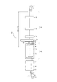
- FIG. 1 is a schematic diagram of a continuous annealing apparatus 100 according to one embodiment of the present invention
- FIG. 1 is a schematic diagram of a continuous hot dip galvanizing apparatus 200 according to one embodiment of the present invention
- FIG. FIG. 3 is a schematic diagram of a continuous hot-dip galvanizing apparatus 300 according to another embodiment of the present invention
- 1 is a schematic diagram showing the configuration of a vibration adding device 60 used in each embodiment of the present invention
- FIG. (A) and (B) are diagrams schematically showing an example of an installation mode of an electromagnet 63 of a vibration adding device 60 with respect to a cold-rolled steel sheet S being threaded in each embodiment of the present invention.
- FIG. 1 is a schematic diagram showing the configuration of a vibration adding device 70 used in each embodiment of the present invention
- FIG. 4 is a diagram schematically showing an example of an installation mode of a vibrator 72 of a vibration adding device 70 with respect to a cold-rolled steel sheet S being threaded.
- FIG. 1 and (B) are schematic diagrams showing an example of the positional relationship between the cooling nozzle 26A and the vibration adding device 60 or 70 when the vibration adding device 60 or 70 is installed in the cooling zone 26.
- One embodiment of the present invention relates to a continuous annealing line (CAL), and another embodiment of the present invention relates to a continuous hot-dip galvanizing line (CGL). is.
- CAL continuous annealing line
- CGL continuous hot-dip galvanizing line
- a steel sheet manufacturing method is realized by a continuous annealing line (CAL) or a continuous hot-dip galvanizing line (CGL).
- CAL continuous annealing line
- CGL continuous hot-dip galvanizing line
- a continuous annealing apparatus (CAL) 100 includes a pay-off reel 10 for dispensing cold-rolled steel sheet S from a cold-rolled coil C, and a cold-rolled steel sheet S for threading.
- An annealing furnace 20 for continuous annealing, a downstream facility 30 for continuously threading the cold-rolled steel sheet S discharged from the annealing furnace 20, and the cold-rolled steel sheet S being threaded in the downstream facility 30 is wound up to produce a product coil P and a tension reel 50.
- a heating zone 22, a soaking zone 24, and a cooling zone 26 are positioned from the upstream side in the sheet passing direction.
- the cold rolled steel sheet S is annealed in a reducing atmosphere containing hydrogen.
- the cold-rolled steel sheet S is cooled in the cooling zone 26 .
- the annealing furnace 20 of CAL100 preferably has an overaging treatment zone 28 downstream of the cooling zone 26, but this is not essential. In the overaging zone 28, the cold-rolled steel sheet S is overaged.
- CAL 100 produces product coils of cold-rolled and annealed steel sheets (CR).
- the steel sheet manufacturing method realized by a continuous annealing apparatus (CAL) 100 includes (A) a cold-rolled steel sheet (steel strip) S from a cold-rolled coil C by a pay-off reel 10; (B) Passing the cold-rolled steel sheet S through the annealing furnace 20 in which the heating zone 22, the soaking zone 24, and the cooling zone 26 are located from the upstream side in the sheet passing direction, (B-1 ) annealing the cold-rolled steel sheet S in a reducing atmosphere containing hydrogen in the heating zone 22 and the soaking zone 24, and (B-2) cooling the cold-rolled steel sheet S in the cooling zone 26, performing continuous annealing; C) a step of continuously threading the cold-rolled steel sheet S discharged from the annealing furnace 20; In the continuous annealing step (B) in the annealing furnace 20 of CAL100, (B-3) it is preferable to subject the cold-rolled steel sheet S to an overaging treatment in an overaging treatment zone 28
- a continuous hot-dip galvanizing apparatus (CGL) 200 includes a pay-off reel 10 for dispensing a cold-rolled steel sheet S from a cold-rolled coil C, and a cold-rolled steel sheet S
- An annealing furnace 20 for continuously annealing a sheet
- a downstream facility 30 for continuously threading the cold-rolled steel sheet S discharged from the annealing furnace 20, and the cold-rolled steel sheet S being threaded in the downstream facility 30 is wound up to produce a product.
- a tension reel 50 as a coil P.
- a heating zone 22, a soaking zone 24, and a cooling zone 26 are positioned from the upstream side in the sheet passing direction.
- the cold rolled steel sheet S is annealed in a reducing atmosphere containing hydrogen.
- the cold-rolled steel sheet S is cooled in the cooling zone 26 .
- the CGL 200 is positioned downstream of the annealing furnace 20 in the direction of sheet passing as a downstream facility 30, and immerses the cold-rolled steel sheet S in a hot-dip galvanizing bath 31 for hot-dip galvanizing the cold-rolled steel sheet S; It further has an alloying furnace 33 which is located downstream of the plating bath 31 in the sheet passing direction, passes the cold-rolled steel sheet S, and heats and alloys the hot-dip galvanized steel sheet.
- the CGL 200 produces a product coil of alloyed hot-dip galvanized steel sheet (GA) in which the galvanized layer is alloyed.
- GA alloyed hot-dip galvanized steel sheet
- GI hot-dip galvanized steel sheet
- the steel sheet manufacturing method realized by a continuous hot dip galvanizing apparatus (CGL) 200 includes (A) a cold-rolled steel sheet (steel strip) from a cold-rolled coil C by a payoff reel 10; (B) passing the cold-rolled steel sheet S through an annealing furnace 20 in which a heating zone 22, a soaking zone 24, and a cooling zone 26 are positioned from the upstream side in the sheet passing direction; -1) A step of continuously annealing the cold-rolled steel sheet S in a reducing atmosphere containing hydrogen in the heating zone 22 and the soaking zone 24, and (B-2) cooling the cold-rolled steel sheet S in the cooling zone 26; , (C) a step of continuously threading the cold-rolled steel sheet S discharged from the annealing furnace 20, and (D) a step of winding the cold-rolled steel sheet S by the tension reel 50 to form a product coil P, in this order.
- a cold-rolled steel sheet (steel strip) from a cold-rolled coil C by a payoff
- step (C) is (C-1) a step of immersing the cold-rolled steel sheet S in a hot-dip galvanizing bath 31 located downstream of the annealing furnace 20 in the sheet running direction to apply hot-dip galvanization to the cold-rolled steel sheet S.
- step (C-2) the cold-rolled steel sheet S is passed through an alloying furnace 33 located downstream of the hot-dip galvanizing bath 31 in the sheet-passing direction to heat-alloy the hot-dip galvanized steel.
- This embodiment is a method of manufacturing a product coil of an alloyed hot-dip galvanized steel sheet (GA) in which a galvanized layer is alloyed by CGL200.
- a continuous hot dip galvanizing apparatus (CGL) 300 according to the third embodiment of the present invention has the same configuration as the CGL 200 except that it does not have an alloying furnace 33.
- the CGL 300 produces product coils of hot-dip galvanized steel sheets (GI) in which the galvanized layer is unalloyed.
- GI hot-dip galvanized steel sheets
- the steel sheet manufacturing method according to the third embodiment in which the step (C-1) is performed and the step (C-2) is not performed is realized by, for example, the CGL 300 without the alloying furnace 33, and the CGL 200 It can also be realized by a method in which the steel plate S is passed through the alloying furnace 33 without heat alloying.
- This embodiment is a method of manufacturing a product coil of a hot-dip galvanized steel sheet (GI) in which the galvanized layer is not alloyed by CGL200 or CGL300.
- GI hot-dip galvanized steel sheet
- Step (A) a payoff reel 10 pays out a cold-rolled steel sheet S from a cold-rolled coil C. As shown in FIG. That is, in step (A), the cold-rolled steel sheet S is paid out from the cold-rolled coil C by the pay-off reel 10 .
- the discharged cold-rolled steel sheet S passes through the welding machine 11 , the cleaning equipment 12 and the entrance looper 13 and is supplied to the annealing furnace 20 .
- the upstream equipment between the payoff reel 10 and the annealing furnace 20 is not limited to the welding machine 11, the cleaning equipment 12, and the entrance looper 13, and may be known or arbitrary equipment.
- an annealing furnace 20 continuously anneals a cold-rolled steel sheet S through which it passes.
- a heating zone 22 a soaking zone 24, and a cooling zone 26 are positioned from the upstream side in the sheet passing direction.
- the cold rolled steel sheet S is annealed in a reducing atmosphere containing hydrogen.
- the cold-rolled steel sheet S is cooled in the cooling zone 26 .
- step (B) the cold-rolled steel sheet S is passed through an annealing furnace 20 in which a heating zone 22, a soaking zone 24, and a cooling zone 26 are positioned from the upstream side in the sheet-passing direction, and continuous annealing is performed.
- the cooling zone 26 may be composed of multiple cooling zones. Further, a preheating zone may be provided on the upstream side of the heating zone 22 in the sheet threading direction.
- the annealing furnace 20 of the CAL 100 shown in FIG. 1 preferably has an overaging treatment zone 28 downstream of the cooling zone 26, but this is not essential.
- each belt is illustrated as a vertical furnace, but it is not limited to this, and may be a horizontal furnace. In the case of a vertical furnace, adjacent strips communicate through throats (throttles) connecting the upper parts or the lower parts of the respective strips.
- the cold-rolled steel sheet S can be directly heated using a burner, or indirectly heated using a radiant tube (RT) or an electric heater. Heating by induction heating, roll heating, electric resistance heating, direct electric heating, salt bath heating, electron beam heating, etc. is also possible.
- the average temperature inside the heating zone 22 is preferably 500-800.degree.
- a reducing gas is separately supplied.
- an H 2 -N 2 mixed gas is usually used, for example, H 2 : 1 to 35% by volume, the balance being one or both of N 2 and Ar and inevitable impurities (dew point : about -60°C).
- the cold-rolled steel sheet S can be indirectly heated using a radiant tube (RT).
- the average temperature inside the soaking zone 24 is preferably 600 to 950°C.
- a reducing gas is supplied to the soaking zone 24 .
- an H 2 -N 2 mixed gas is usually used, for example, H 2 : 1 to 35% by volume, the balance being one or both of N 2 and Ar and inevitable impurities (dew point : about -60°C).
- cooling zone 26 In the cooling zone 26, the cold-rolled steel sheet S is cooled by either gas, a mixture of gas and water, or water. The cold-rolled steel sheet S is cooled to about 100 to 400° C. for CAL and to about 470 to 530° C. for CGL at the stage of leaving the annealing furnace 20 . As shown in FIGS. 8A and 8B, the cooling zone 26 is provided with a plurality of cooling nozzles 26A along the steel sheet conveying path.
- the cooling nozzle 26A is, for example, a circular pipe longer than the width of the steel plate, as described in Japanese Unexamined Patent Application Publication No. 2010-185101, and is installed so that the extending direction of the circular pipe is parallel to the width direction of the steel plate. .
- the circular pipe is provided with a plurality of through-holes at a predetermined interval along the extending direction of the circular pipe at a portion facing the steel plate, and the water inside the circular pipe is jetted from the through-holes toward the steel plate.
- a pair of cooling nozzles are provided so as to face the front and back of the steel plate, and a plurality of pairs (for example, 5 to 10 pairs) of cooling nozzles are arranged at predetermined intervals along the steel plate conveying path to form one cooling zone. Constitute. It is preferable to arrange about 3 to 6 cooling zones along the steel plate conveying path.
- cold-rolled steel sheet S exiting cooling zone 26 is subjected to at least one treatment of isothermal holding, reheating, furnace cooling, and air cooling.
- the rolled steel sheet S is cooled to about 100 to 400° C. at the stage of leaving the annealing furnace 20 .
- step (C) the cold-rolled steel sheet S discharged from the annealing furnace 20 is continuously passed through the downstream facility 30.
- CGL 100 has a delivery side looper 35 and a temper rolling mill 36 as downstream equipment 30 .
- CGL 200 has, as downstream equipment 30 , hot dip galvanizing bath 31 , gas wiping device 32 , alloying furnace 33 , cooling device 34 , exit looper 35 , and temper rolling mill 36 .
- CGL 300 has, as downstream equipment 30 , hot dip galvanizing bath 31 , gas wiping device 32 , cooling device 34 , delivery side looper 35 , and temper rolling mill 36 .
- the downstream equipment 30 is not limited to these, and may be known or arbitrary equipment.
- the downstream equipment 30 can include tension levelers, chemical conversion equipment, surface conditioning equipment, oiling equipment, and inspection equipment.
- the hot-dip galvanizing bath 31 is located downstream of the annealing furnace 20 in the direction of sheet feeding, immerses the cold-rolled steel sheet S, and hot-dip galvanizes the cold-rolled steel sheet S.
- the cold-rolled steel sheet S is immersed in a hot-dip galvanizing bath 31 located downstream of the annealing furnace 20 in the sheet-threading direction, and the cold-rolled steel sheet S is hot-dip galvanized.
- the snout 29 connected to the most downstream zone (cooling zone 26 in FIGS.
- Hot-dip galvanizing may be performed according to a standard method.
- the alloying furnace 33 is located downstream of the hot dip galvanizing bath 31 and the gas wiping device 32 in the sheet passing direction, passes the cold rolled steel sheet S, and heats and alloys the hot dip galvanized. . That is, in the step (C-2), the cold-rolled steel sheet S is passed through an alloying furnace 33 located downstream of the hot dip galvanizing bath 31 and the gas wiping device 32 in the sheet passing direction, and the hot dip galvanized is heated and alloyed. do.
- the alloying treatment may be performed according to a standard method.
- the heating means in the alloying furnace 33 is not particularly limited, and examples thereof include heating with high-temperature gas and induction heating. However, the alloying furnace 33 is optional equipment in the CGL, and the alloying process is an optional process in the steel sheet manufacturing method using the CGL.
- the cooling device 34 is located downstream of the gas wiping device 32 and the alloying furnace 33 in the sheet passing direction.
- the cold-rolled steel sheet S can be cooled by passing the cold-rolled steel sheet S through the cooling device 34 .
- the cooling device 34 cools the cold-rolled steel sheet S by water cooling, air cooling, gas cooling, mist cooling, or the like.
- the CAL 100 of the first embodiment, the CGL 200 of the second embodiment, and the CGL 300 of the third embodiment add vibration to the cold-rolled steel sheet S being threaded from the cooling band 26 to the tension reel 50. It is essential to have a vibration adding device 60 or 70 that That is, in the steel sheet manufacturing methods according to the first, second, and third embodiments, after the step (B-2) and before the step (D), the cold-rolled steel sheet S being threaded is It is essential to include a vibration adding step of adding vibrations at the bottom.
- the vibration applied to the cold-rolled steel sheet S by the vibration adding device 60 or 70 has a vibration frequency of 100 Hz or more and 100000 Hz or less, and a maximum amplitude of the cold-rolled steel sheet S of 10 nm or more and 500 ⁇ m or less. It is essential to be something. As a result, the hydrogen contained in the cold-rolled steel sheet S can be sufficiently and efficiently reduced by annealing, and a steel sheet having excellent resistance to hydrogen embrittlement can be produced. Moreover, since vibration application is incorporated into the steel plate manufacturing process (in-line) by CAL100, CGL200 or CGL300, production efficiency is not impaired. In addition, since hydrogen is desorbed not by heating but by applying vibration, there is no fear of changing the mechanical properties of the steel sheet.
- vibration adding device 60 Each embodiment of the present invention can be realized by installing a vibration adding device 60 as shown in FIG. Vibration is added to the rolled steel sheet S.
- vibration adding device 60 includes controller 61 , amplifier 62 , electromagnet 63 , vibration detector 64 and power supply 65 .
- vibration adding device 60 has electromagnet 63 including magnet 63A and coil 63B winding magnet 63A. has a magnetic pole face 63A1 spacedly opposed to the surface of the .
- the vibration adding device 60 is configured to vibrate the cold-rolled steel sheet S by an external force (attractive force) applied to the cold-rolled steel sheet S by the electromagnet 63 .
- the electromagnet 63 has a magnetic pole face 63A1 that faces the surface of the cold-rolled steel sheet S with a gap therebetween, its shape and installation mode are not limited. As a result, as shown in FIGS. 6A and 6B, the direction of the magnetic lines of force becomes perpendicular to the cold-rolled steel sheet S, and an attractive force can be exerted on the cold-rolled steel sheet S. Examples of the shape and installation mode of the electromagnet are shown in FIGS. 5A and 5B.
- the rectangular parallelepiped electromagnet 63 extends along the width direction of the steel sheet with a predetermined gap from the surface of the cold-rolled steel sheet S.
- An external force (attractive force) can be applied uniformly in the width direction of the , and uniform vibration in the width direction can be realized.
- the electromagnet 63 has a magnet 63A and a coil 63B wound therearound. In this case, depending on the direction of the current flowing through the coil 63B, as shown in FIG. , the magnetic pole surface 63A1 facing the cold-rolled steel sheet S becomes the S pole.
- a plurality of columnar electromagnets 63 are arranged at predetermined intervals along the width direction of the steel sheet S so that the magnetic pole faces at the bottom face the surface of the cold-rolled steel sheet S with a space therebetween.
- an external force attractive force
- each electromagnet 63 has a cylindrical magnet and a coil wound around it, and the axial direction of the coil coincides with the thickness direction of the cold-rolled steel sheet S.
- the magnetic pole surface 63A1 facing the cold-rolled steel sheet S becomes the N pole as shown in FIG.
- the magnetic pole surface 63A1 facing the cold-rolled steel sheet S becomes the S pole.
- an external force acts on the cold-rolled steel sheet S by applying a current to the electromagnet 63 .
- the current supplied to the electromagnet 63 is a direct current pulse current or an alternating current continuous current.
- a DC pulse current is applied to the electromagnet 63
- the cold-rolled steel sheet S vibrates due to intermittent attractive force acting on the cold-rolled steel sheet S.
- a continuous alternating current is passed through the electromagnet, the magnetic pole surface 63A1 facing the cold-rolled steel sheet S switches between the N pole and the S pole each time the direction of the current changes.
- An external force acts.
- the magnitude of the external force (attractive force) acting on the cold-rolled steel sheet S also changes according to the change in the current value over time, the cold-rolled steel sheet S vibrates.
- the electromagnet 63 it is sufficient to provide the electromagnet 63 so as to face one surface of the cold-rolled steel sheet S, but it may be provided so as to face both the front and back surfaces. However, in that case, it is preferable to shift the height position so that the electromagnet on one side is not at the same height position as the electromagnet on the other side.
- the vibration detector 64 shown in FIG. 4 is a laser displacement meter or a laser Doppler vibrometer arranged at a predetermined distance from the surface of the cold-rolled steel sheet S, and measures the frequency and amplitude of the vibration of the cold-rolled steel sheet S. be able to. By disposing the vibration detector 64 at the same height position as the electromagnet 63 of the cold-rolled steel sheet S, the vibration detector 64 can measure the maximum amplitude of the vibration of the cold-rolled steel sheet S. The frequency and maximum amplitude detected by vibration detector 64 are output to controller 61 .
- the controller 61 receives the values of the frequency and maximum amplitude output from the vibration detector 64, compares them with the set values, performs PID calculation on the deviation, etc., and controls the cold-rolled steel sheet S at a predetermined frequency and maximum amplitude.
- the frequency of the electromagnet 63 (the frequency of the DC pulse current or the frequency of the continuous AC current) and the current value are determined so as to oscillate, and the current value to be given to the amplifier 62 is determined in consideration of the amplification factor of the amplifier 62. and gives a command value to the power supply 65 .
- the power supply 65 is a power supply for supplying current to the coil of the electromagnet 63, receives a command value input from the controller 61, and provides the amplifier 62 with current having a predetermined frequency and current value.
- the amplifier 62 amplifies the current value given from the power supply 65 with a predetermined amplification factor and gives a command value to the electromagnet 63 .
- a current with a predetermined frequency and current value flows through the electromagnet 63, and the cold-rolled steel sheet S can be vibrated at a predetermined frequency and maximum amplitude.
- vibration adding device 70 Each embodiment of the present invention can be realized by installing a vibration adding device 70 as shown in FIG. Vibration is added to the rolled steel sheet S.
- vibration adding device 70 includes controller 71 , vibrator 72 , and vibration detector 73 .
- the vibration adding device 70 has a vibrator 72 that contacts the cold-rolled steel sheet S, and is configured to vibrate the cold-rolled steel sheet S with the vibrator 72 .
- the vibrator 72 is not particularly limited as long as it is a general piezoelectric element, and its shape and installation mode are also not limited. For example, as shown in FIG. is brought into surface contact with the cold-rolled steel sheet S, the cold-rolled steel sheet S can be vibrated.
- the vibrator 72 it is sufficient to provide the vibrator 72 so as to be in contact with one surface of the cold-rolled steel sheet S, but it may be provided so as to be in contact with both the front and back surfaces. However, in that case, it is preferable to shift the height position so that the vibrator on one side is not at the same height position as the vibrator on the other side.
- the vibration detector 73 shown in FIG. 7A is a laser displacement meter or a laser Doppler vibrometer arranged at a predetermined distance from the surface of the cold-rolled steel sheet S, and measures the frequency and amplitude of the vibration of the cold-rolled steel sheet S. be able to. By arranging the vibration detector 73 at the same height position as the vibrator 72 of the cold-rolled steel sheet S, the maximum amplitude of vibration of the cold-rolled steel sheet S can be measured by the vibration detector 73 . The frequency and maximum amplitude detected by vibration detector 73 are output to controller 71 .
- the controller 71 receives the values of the frequency and maximum amplitude output from the vibration detector 73, compares them with the set values, performs PID calculation on the deviation, etc., and controls the cold-rolled steel sheet S at a predetermined frequency and maximum amplitude.
- the frequency and current value of the DC pulse current flowing through the vibrator 72 are determined so as to vibrate the vibrator 72, and a power source (not shown) is controlled to give the vibrator 72 a DC pulse current of a predetermined frequency and current value.
- the vibrator 72 vibrates at a predetermined frequency and amplitude, and as a result, the cold-rolled steel sheet S can be vibrated at a predetermined frequency and maximum amplitude.
- the position of the vibration applying device 60 or 70 is such that vibration can be applied to the cold-rolled steel sheet S being threaded from the cooling band 26 to the tension reel 50. as unrestricted as possible.
- a suitable position of the vibration applying device 60 or 70 that is, a suitable execution timing of the vibration applying process is explain.
- a vibration applicator 60 or 70 may be provided on the cooling zone 26 .
- the vibration application step can be performed in step (B-2).
- the electromagnet 63 shown in FIG. 4 or the electromagnet 63 shown in FIG. , B can be installed.
- 8A and 8B show examples of the positional relationship between the cooling nozzle 26A and the vibration adding device 60 or 70 when the vibration adding device 60 or 70 is installed in the cooling zone 26.
- FIG. It should be noted that the entire vibration adding device 60 or 70 does not have to be positioned inside the cooling zone 26 , and at least the electromagnet 63 or the vibrator 72 may be positioned inside the cooling zone 26 .
- the vibration applying device 60 or 70 can be provided at a position where vibration can be applied to the cold-rolled steel sheet S being passed through the downstream facility 30 .
- the vibration application step can be performed in step (C). Specifically, (i) between the overaging treatment zone 28 and the delivery side looper 35, (ii) within the delivery side looper 35, (iii) between the delivery side looper 35 and the temper rolling mill 36, (iv) )
- a vibration adding device 60 or 70 can be provided at least one between the temper rolling mill 36 and the tension reel 50 .
- the vibration applying device 60 or 70 may be provided both in the cooling zone 26 and in a position where vibration can be applied to the cold-rolled steel sheet S being passed through the downstream equipment 30 . That is, the vibration application step may be performed in both step (B-2) and step (C). Moreover, the vibration applying device 60 or 70 may be provided in the overaging treatment zone 28 to perform the vibration applying process during the overaging treatment.
- the preferred position of the vibration applying device 60 or 70 that is, the preferred position of the vibration applying process I will explain the implementation timing.
- the vibration applying device 60 or 70 can be provided upstream from the hot-dip galvanizing bath 31 at a first position where vibration can be applied to the cold-rolled steel sheet S being passed.
- the vibration application step can be performed before step (C-1).
- a vibration adding device 60 or 70 may be provided in the cooling zone 26 .
- the electromagnet 63 shown in FIG. 4 or the electromagnet 63 shown in FIG. A vibrator 72 shown in 7A and 7B can be installed.
- the entire vibration adding device 60 or 70 does not need to be positioned inside the cooling zone 26 , and at least the electromagnet 63 or the vibrator 72 may be positioned inside the cooling zone 26 . Also, at least the electromagnet 63 or vibrator 72 of the vibration adding device 60 or 70 can be installed in the snout 29 .
- the vibration applying device 60 or 70 can be provided downstream from the hot dip galvanizing bath 31 at a second position where vibration can be applied to the cold-rolled steel sheet S being passed.
- the vibration applying step can be performed after the step (C-1). Specifically, (i) between the hot dip galvanizing bath 31 and the gas wiping device 32, (ii) between the gas wiping device 32 and the alloying furnace 33, (iii) inside the alloying furnace 33, and (iv) Air cooling zone between the alloying furnace 33 and the cooling device 34, (v) between the cooling device 34 and the delivery side looper 35, (vi) within the delivery side looper 35, (vii) the delivery side looper 35 and temper rolling (viii) between the temper mill 36 and the tension reel 50.
- the vibration applying device 60 or 70 is preferably provided at the first position rather than at the second position. That is, the vibration application step is preferably performed before step (C-1) rather than after step (C-1). However, the vibration adding device 60 or 70 may be provided at both the first position and the second position. That is, the vibration applying step may be performed both before and after the step (C-1).
- the preferred position of the vibration adding device 60 or 70 that is, the preferred execution of the vibration adding process Explain timing.
- the vibration applying device 60 or 70 can be provided upstream from the hot-dip galvanizing bath 31 at a first position where vibration can be applied to the cold-rolled steel sheet S being passed.
- the vibration application step can be performed before step (C-1).
- a vibration adding device 60 or 70 may be provided in the cooling zone 26 .
- the electromagnet 63 shown in FIG. 4 or the electromagnet 63 shown in FIG. A vibrator 72 shown in 7A and 7B can be installed.
- the entire vibration adding device 60 or 70 does not need to be positioned inside the cooling zone 26 , and at least the electromagnet 63 or the vibrator 72 may be positioned inside the cooling zone 26 . Also, at least the electromagnet 63 or vibrator 72 of the vibration adding device 60 or 70 can be installed in the snout 29 .
- the vibration applying device 60 or 70 can be provided downstream from the hot dip galvanizing bath 31 at a second position where vibration can be applied to the cold-rolled steel sheet S being passed.
- the vibration applying step can be performed after the step (C-1). Specifically, (i) between the hot dip galvanizing bath 31 and the gas wiping device 32, (ii) an air cooling zone between the gas wiping device 32 and the cooling device 34, and (iii) the cooling device 34 and the outlet looper 35, (iv) inside the delivery side looper 35, (v) between the delivery side looper 35 and the temper mill 36, and (vi) between the temper mill 36 and the tension reel 50.
- a vibration adding device 60 or 70 can be provided. In particular, it is preferable to provide the vibration adding device 60 or 70 in the air cooling zone (ii).
- the vibration applying device 60 or 70 is preferably provided at the first position rather than at the second position. That is, the vibration application step is preferably performed before step (C-1) rather than after step (C-1). However, the vibration adding device 60 or 70 may be provided at both the first position and the second position. That is, the vibration applying step may be performed both before and after the step (C-1).
- the vibration frequency of the cold-rolled steel sheet S is 100 Hz or higher. If the frequency is less than 100 Hz, the effect of desorbing hydrogen contained in the cold-rolled steel sheet S cannot be obtained. From this point of view, the frequency is 100 Hz or higher, preferably 500 Hz or higher, and more preferably 1000 Hz or higher.
- the cold-rolled steel sheet S naturally vibrates during the sheet threading process, or vibrates by receiving gas from the gas wiping device 32, for example. However, in these vibrations, the vibration frequency of the cold-rolled steel sheet S is at most about 20 Hz, and in this case, the effect of desorbing hydrogen contained in the cold-rolled steel sheet S cannot be obtained.
- the frequency be 100,000 Hz or less, preferably 80,000 Hz or less, and more preferably 50,000 Hz or less.
- the vibration frequency of the cold-rolled steel sheet S can be measured by the vibration detector 64 shown in FIG. 4 or the vibration detector 73 shown in FIG. 7A.
- the vibration frequency of the cold-rolled steel sheet S can be adjusted by controlling the frequency of the DC pulse current or the frequency of the AC continuous current.
- the vibration applying device 70 shown in B it can be adjusted by controlling the vibration frequency of the vibrator 72 .
- the maximum amplitude of the cold-rolled steel sheet S is 10 nm or more, preferably 100 nm or more, and more preferably 500 nm or more.
- the maximum amplitude of the cold-rolled steel sheet S exceeds 500 ⁇ m, the strain on the steel sheet surface increases, plastic deformation occurs, and as a result hydrogen is trapped, so hydrogen contained in the cold-rolled steel sheet S is removed.
- the maximum amplitude of the cold-rolled steel sheet S is 500 ⁇ m or less, preferably 400 ⁇ m or less, and more preferably 300 ⁇ m or less.
- the cold-rolled steel sheet S naturally vibrates during the sheet threading process, or vibrates by receiving gas from the gas wiping device 32, for example.
- the maximum amplitude of the cold-rolled steel sheet S exceeds at least 0.5 mm, the effect of desorbing hydrogen contained in the cold-rolled steel sheet S cannot be obtained.
- the maximum amplitude of the cold-rolled steel sheet S can be measured by the vibration detector 64 shown in FIG. 4 or the vibration detector 73 shown in FIG. 7A.
- the maximum amplitude of the cold-rolled steel sheet S can be adjusted by controlling the amount of current flowing through the electromagnet 63 in the case of the vibration adding device 60 shown in FIG. can be adjusted by controlling the amplitude of the vibration of the vibrator 72 .
- the vibration application time to the cold-rolled steel sheet S is preferably 1 second or longer, more preferably 5 seconds or longer. Seconds or longer is more preferable.
- the duration of vibration applied to the cold-rolled steel sheet S is preferably 3600 seconds or less, more preferably 1800 seconds or less, and even more preferably 900 seconds or less.
- vibration application time to the cold-rolled steel sheet S means the time during which vibration is applied to each position on the surface of the cold-rolled steel sheet S, and each position is provided with a plurality of vibration applying devices 60 or 70 .
- vibration When vibration is given from , it means the accumulated time.
- vibration applying device 60 when vibration applying device 60 is used, it can be considered that the portion of the surface of cold-rolled steel sheet S facing electromagnet 63 is vibrating. Therefore, the sum of the times during which each part of the cold-rolled steel sheet S faces the electromagnet 63 can be used as the vibration addition time.
- the vibration adding device 70 shown in FIGS. 7A and 7B the cumulative time during which each part of the cold-rolled steel sheet S is in contact with the vibrator 72 can be used as the vibration adding time.
- the vibration application time depends on the threading speed of the cold-rolled steel sheet S and the position of the vibration applying device 60 or 70 (for example, the number of electromagnets 63 shown in FIG. 72 along the threading direction).
- the cold-rolled steel sheet S supplied to CAL100, CGL200 and CGL300 is not particularly limited.
- the cold-rolled steel sheet S preferably has a thickness of less than 6 mm, and includes, for example, a high-strength steel sheet having a tensile strength of 590 MPa or more and a stainless steel sheet.
- C 0.030-0.800% C has the effect of increasing the strength of the steel sheet. From the viewpoint of obtaining this effect, the amount of C should be 0.030% or more, preferably 0.080% or more. However, when the amount of C is excessive, the steel sheet becomes significantly embrittled regardless of the amount of hydrogen in the steel sheet. Therefore, the amount of C should be 0.800% or less, preferably 0.500% or less.
- Si 0.01-3.00% Si has the effect of increasing the strength of the steel sheet. From the viewpoint of obtaining this effect, the amount of Si should be 0.01% or more, preferably 0.10% or more. However, when the amount of Si is excessive, the steel sheet becomes embrittled and the ductility is lowered, red scales are generated, the surface properties are deteriorated, and the plating quality is lowered. Therefore, the Si content is 3.00% or less, preferably 2.50% or less.
- Mn 0.01-10.00%
- Mn has the effect of increasing the strength of the steel sheet through solid-solution strengthening. From the viewpoint of obtaining this effect, the amount of Mn should be 0.01% or more, preferably 0.5% or more. However, when the amount of Mn is excessive, unevenness tends to occur in the steel structure due to the segregation of Mn, and hydrogen embrittlement starting from the unevenness may occur. Therefore, the Mn content is set to 10.00% or less, preferably 8.00% or less.
- P 0.001 to 0.100%
- P is an element that has a solid-solution strengthening action and can be added according to the desired strength. From the viewpoint of obtaining such effects, the amount of P should be 0.001% or more, preferably 0.003% or more. However, when the amount of P is excessive, the weldability deteriorates, and when the zinc plating is alloyed, the alloying speed decreases and the quality of the zinc plating deteriorates. Therefore, the P content is set to 0.100% or less, preferably 0.050% or less.
- S 0.0001 to 0.0200% S segregates at grain boundaries to embrittle the steel during hot working, and also exists as sulfides to reduce local deformability. Therefore, the S content is 0.0200% or less, preferably 0.0100% or less, more preferably 0.0050% or less. On the other hand, the amount of S is set to 0.0001% or more due to production technology restrictions.
- N 0.0005 to 0.0100% N is an element that deteriorates the aging resistance of steel. Therefore, the N content is set to 0.0100% or less, preferably 0.0070% or less. The smaller the amount of N, the better, but due to production technology restrictions, the amount of N is set to 0.0005% or more, preferably 0.0010% or more.
- Al acts as a deoxidizing agent and is an element effective for the cleanliness of steel. From the viewpoint of obtaining this effect, the amount of Al should be 0.001% or more, preferably 0.010% or more. However, if the amount of Al is excessive, there is a possibility that cracks will occur during continuous casting. Therefore, the Al content is set to 2.000% or less, preferably 1.200% or less.
- the balance other than the above components is Fe and unavoidable impurities. However, it may optionally contain at least one element selected from the following.
- Ti 0.200% or less Ti contributes to an increase in the strength of the steel sheet by precipitation strengthening of the steel and fine grain strengthening by suppressing the growth of ferrite crystal grains. Therefore, when adding Ti, the amount of Ti is preferably 0.005% or more, more preferably 0.010% or more. However, if the amount of Ti is excessive, a large amount of carbonitrides may be precipitated and formability may deteriorate. Therefore, when adding Ti, the amount of Ti should be 0.200% or less, preferably 0.100% or less.
- Nb 0.200% or less
- V 0.500% or less
- W 0.500% or less
- Nb, V, and W are effective for precipitation strengthening of steel. Therefore, when Nb, V, and W are added, the content of each element is preferably 0.005% or more, more preferably 0.010% or more. However, if each content is excessive, a large amount of carbonitrides may be precipitated and formability may be lowered. Therefore, when Nb is added, the amount of Nb should be 0.200% or less, preferably 0.100% or less. When V and W are added, the content of each element should be 0.500% or less, preferably 0.300% or less.
- B 0.0050% or less B is effective for strengthening grain boundaries and increasing the strength of steel sheets. Therefore, when adding B, the amount of B is preferably 0.0003% or more. However, when the amount of B is excessive, moldability may deteriorate. Therefore, when adding B, the amount of B should be 0.0050% or less, preferably 0.0030% or less.
- Ni 1.000% or less
- Ni is an element that increases the strength of steel through solid-solution strengthening. Therefore, when Ni is added, the amount of Ni is preferably 0.005% or more. However, when the amount of Ni is excessive, the area ratio of hard martensite becomes excessive, and microvoids at grain boundaries of martensite increase during tensile tests, furthermore, propagation of cracks progresses, resulting in ductility. may decrease. Therefore, when Ni is added, the amount of Ni should be 1.000% or less.
- Cr 1.000% or less
- Mo 1.000% or less Cr and Mo have the effect of improving the balance between strength and formability. Therefore, when Cr and Mo are added, the content of each element is preferably 0.005% or more. However, if each content is excessive, the area ratio of hard martensite becomes excessive, and microvoids at grain boundaries of martensite increase during tensile tests, and crack propagation progresses. Ductility may decrease. Therefore, when Cr and Mo are added, the content of each element should be 1.000% or less.
- Cu 1.000% or less
- Cu is an element effective in strengthening steel. Therefore, when adding Cu, the amount of Cu is preferably 0.005% or more. However, when the amount of Cu is excessive, the area ratio of hard martensite becomes excessive, and microvoids at grain boundaries of tempered martensite increase during a tensile test, and crack propagation progresses. Ductility may decrease. Therefore, when adding Cu, the amount of Cu is set to 1.000% or less.
- Sn 0.200% or less
- Sb 0.200% or less
- Sn and Sb suppress decarburization of a region of about several tens of ⁇ m in the surface layer of the steel sheet caused by nitridation or oxidation of the steel sheet surface, and improve strength and material stability. It is effective in securing the sex. Therefore, when Sn and Sb are added, the content of each element is preferably 0.002% or more. However, if each content is excessive, the toughness may decrease. Therefore, when Sn and Sb are added, the content of each element should be 0.200% or less.
- Ta 0.100% or less Ta, like Ti and Nb, forms alloy carbides and alloy carbonitrides and contributes to high strength.
- the amount of Ta is preferably 0.001% or more.
- the amount of Ta should be 0.100% or less.
- Ca, Mg, Zr and REM have the shape of sulfides. It is an effective element for spheroidizing and ameliorating the adverse effects of sulfides on formability.
- the content of each element is preferably 0.0005% or more. However, if each content is excessive, inclusions and the like increase, and surface and internal defects may occur. Therefore, when these elements are added, the content of each element should be 0.0050% or less.
- C 0.001 to 0.400%
- C is an essential element for obtaining high strength in stainless steel. However, it combines with Cr during tempering in steel production and precipitates as carbides, which deteriorate the corrosion resistance and toughness of the steel. If the amount of C is less than 0.001%, sufficient strength cannot be obtained, and if it exceeds 0.400%, the above deterioration becomes remarkable. Therefore, the amount of C is set to 0.001 to 0.400%.
- Si 0.01-2.00% Si is an element useful as a deoxidizing agent. From the viewpoint of obtaining this effect, the amount of Si is made 0.01% or more. However, when the amount of Si is excessive, the Si dissolved in the steel reduces the workability of the steel. Therefore, Si should be 2.00% or less.
- Mn 0.01-5.00% Mn has the effect of increasing the strength of steel. From the viewpoint of obtaining this effect, the amount of Mn is set to 0.01% or more. However, when the amount of Mn is excessive, the workability of the steel deteriorates. Therefore, the Mn content is set to 5.00% or less.
- P 0.001 to 0.100%
- P is an element that promotes intergranular fracture due to intergranular segregation. Therefore, the lower the P content is, the more preferably it is 0.100% or less, preferably 0.030% or less, and more preferably 0.020% or less. On the other hand, the amount of P is set to 0.001% or more due to restrictions on production technology.
- S 0.0001 to 0.0200% S exists as sulfide-based inclusions such as MnS and lowers ductility, corrosion resistance, and the like. Therefore, the lower the S content is, the more preferably it is 0.0200% or less, preferably 0.0100% or less, and more preferably 0.0050% or less. On the other hand, the amount of S is set to 0.0001% or more due to production technology restrictions.
- Cr 9.0-28.0%
- Cr is a basic element that constitutes stainless steel, and is an important element that develops corrosion resistance.
- the Cr content is set to 9.0 to 28.0%.
- Ni 0.01-40.0% Ni is an element that improves the corrosion resistance of stainless steel. If the amount of Ni is less than 0.01%, the effect is not sufficiently exhibited. On the other hand, if the amount of Ni is excessive, the formability is deteriorated and stress corrosion cracking is likely to occur. Therefore, the Ni content is set to 0.01 to 40.0%.
- N 0.0005 to 0.500% N is an element harmful to improving the corrosion resistance of stainless steel. Therefore, the N content is set to 0.500% or less, preferably 0.200% or less. The smaller the amount of N, the better, but due to production technology restrictions, the amount of N is set to 0.0005% or more.
- Al 0.001-3.000%
- Al has the effect of suppressing the peeling of oxide scale. From the viewpoint of obtaining these effects, the amount of Al is made 0.001% or more. However, when the amount of Al is excessive, a decrease in elongation and deterioration of surface quality occur. Therefore, the Al content is set to 3.000% or less.
- the balance other than the above components is Fe and unavoidable impurities. However, it may optionally contain at least one element selected from the following.
- Ti 0.500% or less Ti combines with C, N, and S to improve corrosion resistance, intergranular corrosion resistance, and deep drawability. However, when the amount of Ti exceeds 0.500%, the toughness deteriorates due to dissolved Ti. Therefore, when adding Ti, the amount of Ti shall be 0.500% or less.
- Nb 0.500% or less Nb, like Ti, combines with C, N, and S to improve corrosion resistance, intergranular corrosion resistance, and deep drawability. In addition to improving workability and high-temperature strength, it suppresses crevice corrosion and promotes re-passivation. However, excessive addition causes hardening and deteriorates moldability. Therefore, when Nb is added, the amount of Nb should be 0.500% or less.
- V 0.500% or less V suppresses crevice corrosion. However, excessive addition deteriorates moldability. Therefore, when adding V, the amount of V should be 0.500% or less.
- W 2.000% or less W contributes to improvement of corrosion resistance and high-temperature strength.
- excessive addition leads to deterioration of toughness and cost increase during steel sheet production. Therefore, when adding W, the amount of W shall be 2.000% or less.
- B 0.0050% or less B segregates at grain boundaries to improve secondary workability of products.
- excessive addition results in deterioration of workability and corrosion resistance. Therefore, when adding B, the amount of B shall be 0.0050% or less.
- Mo 2.000% or less
- Mo is an element that improves corrosion resistance and particularly suppresses crevice corrosion.
- excessive addition deteriorates moldability. Therefore, when adding Mo, the amount of Mo shall be 2.000% or less.
- Cu 3.000% or less
- Cu is an austenite-stabilizing element and is effective in refining crystal grains by phase transformation. It also promotes suppression of crevice corrosion and re-passivation. However, excessive addition degrades toughness and formability. Therefore, when adding Cu, the amount of Cu is 3.000% or less.
- Sn 0.500% or less Sn contributes to improvement in corrosion resistance and high-temperature strength. However, excessive addition may cause slab cracking during steel sheet production. Therefore, when Sn is added, the amount of Sn should be 0.500% or less.
- Sb 0.200% or less Sb segregates at grain boundaries to increase high-temperature strength. However, excessive addition may cause cracks during welding due to Sb segregation. Therefore, when Sb is added, the amount of Sb should be 0.200% or less.
- Ta 0.100% or less Ta combines with C and N and contributes to the improvement of toughness. However, excessive addition saturates the effect, leading to an increase in production costs. Therefore, when Ta is added, the amount of Ta is set to 0.100% or less.
- Ca, Mg, Zr and REM have the shape of sulfides. It is an effective element for spheroidizing and ameliorating the adverse effects of sulfides on formability.
- the content of each element is preferably 0.0005% or more. However, if each content is excessive, inclusions and the like increase, and surface and internal defects may occur. Therefore, when these elements are added, the content of each element should be 0.0050% or less.
- the amount of diffusible hydrogen in the product coil is preferably 0.50 mass ppm or less, more preferably 0.30 mass ppm or less, and 0 .20 mass ppm or less is more preferable.
- the lower limit of the amount of diffusible hydrogen in the product coil is not specified, the amount of diffusible hydrogen in the product coil can be 0.01 ppm by mass or more due to production technology restrictions.
- the method for measuring the amount of diffusible hydrogen in the product coil is as follows.
- a test piece with a length of 30 mm and a width of 5 mm is taken from the product coil.
- the hot-dip galvanized layer or alloyed hot-dip galvanized layer of the test piece is removed by grinding or alkali.
- the amount of hydrogen released from the test piece is measured by thermal desorption spectrometry (TDS). Specifically, the test piece was continuously heated from room temperature to 300°C at a temperature increase rate of 200°C/h, then cooled to room temperature, and the cumulative amount of hydrogen released from the test piece from room temperature to 210°C was measured. , the amount of diffusible hydrogen in the product coil.
- a steel having a chemical composition with the elements shown in Table 1 and the balance being Fe and unavoidable impurities was melted in a converter and made into a slab by a continuous casting method.
- the obtained slab was hot rolled and cold rolled to obtain a cold rolled coil.
- some levels produced product coils of cold-rolled annealed steel sheets (CR) by CAL shown in FIG. 1, and other levels produced CGL shown in FIG. , produced product coils of hot-dip galvanized steel sheets (GI), and in the remaining levels, produced product coils of alloyed hot-dip galvanized steel sheets (GA) by CGL shown in FIG.
- vibration application location indicates the area where the vibration application process was performed in CAL or CGL, that is, the location where the vibration application device was installed.
- (B-2) means that in CAL and CGL, a vibration adding device was installed in the cooling zone and the vibration adding step was performed in the cooling zone of step (B-2).
- (C) means that in CAL, the vibration applying device is installed at a position where vibration can be applied to the cold-rolled steel sheet being passed through the downstream equipment, and is positioned downstream from the cooling zone and upstream from the tension reel.
- (C-1) Before” is a position downstream of the cooling zone and upstream of the hot dip galvanizing bath in the CGL, specifically, a vibration adding device is installed in the snout 29, and from the step (B-2) It means that the vibration applying step was performed after the step (C-1) and before the step (C-1).
- (C-1) After is a position downstream of the hot dip galvanizing bath and upstream of the tension reel in the CGL, specifically, (i) between the hot dip galvanizing bath 31 and the gas wiping device 32, ( ii) between the gas wiping device 32 and the alloying furnace 33; (iii) within the alloying furnace 33; (iv) an air cooling zone between the alloying furnace 33 and the cooling device 34; (vi) inside the delivery side looper 35; (vii) between the delivery side looper 35 and the temper mill 36; (viii) between the temper mill 36 and the tension reel 50. It means that a vibration applying device is installed in at least one place, and the vibration applying step is performed in at least one of the above (i) to (viii) after the step (C-1).
- the tensile test was performed in accordance with JIS Z 2241 (2011) using a JIS No. 5 test piece that was sampled so that the tensile direction was perpendicular to the rolling direction of the steel plate, and TS (tensile strength) and EL (total elongation) was measured.
- the resistance to hydrogen embrittlement was evaluated as follows from the above tensile test. Good hydrogen embrittlement resistance when the value obtained by dividing the EL of the steel sheet after vibration addition measured above by the EL' when the amount of hydrogen in the steel of the same steel sheet is 0.00 mass ppm is 0.70 or more. I judged. In addition, EL' is obtained by leaving the same steel plate in the atmosphere for a long time to reduce the hydrogen in the steel inside, and then confirming that the amount of hydrogen in the steel was 0.00 ppm by mass by TDS. , was measured by performing a tensile test.
- the vibration application process was performed under the conditions of a predetermined frequency and maximum amplitude, so a steel sheet with excellent resistance to hydrogen embrittlement was produced.
- a steel sheet having excellent hydrogen embrittlement resistance can be manufactured without impairing production efficiency and without changing mechanical properties. be able to.
- REFERENCE SIGNS LIST 100 continuous annealing device 200 continuous hot-dip galvanizing device 300 continuous hot-dip galvanizing device 10 payoff reel 11 welding machine 12 cleaning equipment 13 entrance looper 20 annealing furnace 22 heating zone 24 soaking zone 26 cooling zone 26A cooling nozzle 28 overaging treatment zone 29 Snout 30 Downstream equipment 31 Hot-dip galvanizing bath 32 Gas wiping device 33 Alloying furnace 34 Cooling device 35 Outgoing looper 36 Tempering rolling mill 50
Landscapes
- Chemical & Material Sciences (AREA)
- Engineering & Computer Science (AREA)
- Organic Chemistry (AREA)
- Materials Engineering (AREA)
- Mechanical Engineering (AREA)
- Metallurgy (AREA)
- Physics & Mathematics (AREA)
- Thermal Sciences (AREA)
- Crystallography & Structural Chemistry (AREA)
- Chemical Kinetics & Catalysis (AREA)
- Oil, Petroleum & Natural Gas (AREA)
- Heat Treatment Of Strip Materials And Filament Materials (AREA)
- Coating With Molten Metal (AREA)
Priority Applications (6)
| Application Number | Priority Date | Filing Date | Title |
|---|---|---|---|
| MX2024000684A MX2024000684A (es) | 2021-07-14 | 2022-05-17 | Linea de recocido continua, linea de galvanizacion por inmersion en caliente continua y metodo de produccion de laminas de acero. |
| CN202280048053.3A CN117616138A (zh) | 2021-07-14 | 2022-05-17 | 连续退火装置和连续热浸镀锌装置以及钢板的制造方法 |
| KR1020237045028A KR20240014501A (ko) | 2021-07-14 | 2022-05-17 | 연속 어닐링 장치 및 연속 용융 아연 도금 장치, 그리고 강판의 제조 방법 |
| EP22841787.9A EP4361295A4 (en) | 2021-07-14 | 2022-05-17 | CONTINUOUS ANNEALING APPARATUS, CONTINUOUS HOT-DIP GALVANIZING APPARATUS AND STEEL SHEET MANUFACTURING METHOD |
| JP2022555184A JP7388570B2 (ja) | 2021-07-14 | 2022-05-17 | 連続焼鈍装置及び連続溶融亜鉛めっき装置、並びに鋼板の製造方法 |
| US18/576,365 US20240425959A1 (en) | 2021-07-14 | 2022-05-17 | Continuous annealing line, continuous hot-dip galvanizing line, and steel sheet production method |
Applications Claiming Priority (2)
| Application Number | Priority Date | Filing Date | Title |
|---|---|---|---|
| JP2021-116761 | 2021-07-14 | ||
| JP2021116761 | 2021-07-14 |
Publications (1)
| Publication Number | Publication Date |
|---|---|
| WO2023286440A1 true WO2023286440A1 (ja) | 2023-01-19 |
Family
ID=84919177
Family Applications (1)
| Application Number | Title | Priority Date | Filing Date |
|---|---|---|---|
| PCT/JP2022/020579 Ceased WO2023286440A1 (ja) | 2021-07-14 | 2022-05-17 | 連続焼鈍装置及び連続溶融亜鉛めっき装置、並びに鋼板の製造方法 |
Country Status (7)
| Country | Link |
|---|---|
| US (1) | US20240425959A1 (https=) |
| EP (1) | EP4361295A4 (https=) |
| JP (1) | JP7388570B2 (https=) |
| KR (1) | KR20240014501A (https=) |
| CN (1) | CN117616138A (https=) |
| MX (1) | MX2024000684A (https=) |
| WO (1) | WO2023286440A1 (https=) |
Cited By (6)
| Publication number | Priority date | Publication date | Assignee | Title |
|---|---|---|---|---|
| WO2023181820A1 (ja) * | 2022-03-25 | 2023-09-28 | Jfeスチール株式会社 | 連続焼鈍装置及び連続溶融亜鉛めっき装置、並びに鋼板の製造方法 |
| WO2023181821A1 (ja) * | 2022-03-25 | 2023-09-28 | Jfeスチール株式会社 | 脱水素装置及び鋼板の製造システム、並びに鋼板の製造方法 |
| JP7786652B1 (ja) * | 2024-06-11 | 2025-12-16 | Jfeスチール株式会社 | 溶融亜鉛めっき鋼板及びその製造方法 |
| JP7786653B1 (ja) * | 2024-06-11 | 2025-12-16 | Jfeスチール株式会社 | 溶融亜鉛めっき鋼板及びその製造方法 |
| WO2025258207A1 (ja) * | 2024-06-11 | 2025-12-18 | Jfeスチール株式会社 | 溶融亜鉛めっき鋼板及びその製造方法 |
| WO2025258206A1 (ja) * | 2024-06-11 | 2025-12-18 | Jfeスチール株式会社 | 溶融亜鉛めっき鋼板及びその製造方法 |
Families Citing this family (1)
| Publication number | Priority date | Publication date | Assignee | Title |
|---|---|---|---|---|
| CN120536851B (zh) * | 2025-07-28 | 2025-11-04 | 烟台一诺电子材料有限公司 | 一种镀锡铜丝的表面处理工艺 |
Citations (8)
| Publication number | Priority date | Publication date | Assignee | Title |
|---|---|---|---|---|
| JPS5665934A (en) * | 1979-10-31 | 1981-06-04 | Nippon Parkerizing Co Ltd | Continuous annealing method for steel sheet strip |
| JPS62287019A (ja) * | 1986-06-05 | 1987-12-12 | Nippon Steel Corp | 走行金属板に非接触で振動を付与する方法及び装置 |
| JP2004131794A (ja) * | 2002-10-10 | 2004-04-30 | Nippon Steel Corp | 鋼板の脱水素方法およびそれを用いた鋼板の製造方法 |
| JP2010185101A (ja) | 2009-02-12 | 2010-08-26 | Jfe Steel Corp | 連続焼鈍炉のガスジェット冷却装置 |
| WO2017145322A1 (ja) * | 2016-02-25 | 2017-08-31 | 新日鐵住金株式会社 | 鋼板の製造方法及び鋼板の連続焼鈍装置 |
| WO2019188642A1 (ja) | 2018-03-30 | 2019-10-03 | Jfeスチール株式会社 | 高強度鋼板およびその製造方法 |
| JP2019173099A (ja) * | 2018-03-28 | 2019-10-10 | 日鉄日新製鋼株式会社 | ステンレス鋼材 |
| JP2020153003A (ja) * | 2019-03-22 | 2020-09-24 | Jfeスチール株式会社 | 高強度溶融亜鉛めっき鋼板の製造方法 |
Family Cites Families (7)
| Publication number | Priority date | Publication date | Assignee | Title |
|---|---|---|---|---|
| JPH0633150A (ja) * | 1992-07-15 | 1994-02-08 | Nkk Corp | ストリップクーラ |
| WO2008099457A1 (ja) * | 2007-02-09 | 2008-08-21 | Toshiba Mitsubishi-Electric Industrial Systems Corporation | プロセスラインの制御装置及びその制御方法 |
| CN103938072A (zh) * | 2014-04-10 | 2014-07-23 | 马钢(集团)控股有限公司 | 一种电工钢板及其生产方法 |
| JP7044998B2 (ja) * | 2019-03-22 | 2022-03-31 | Jfeスチール株式会社 | 溶融Zn-Al系めっき鋼板、およびその製造方法 |
| CN111041325B (zh) * | 2019-11-06 | 2021-03-23 | 中天钢铁集团有限公司 | 一种手工工具用钢的生产方法 |
| US20230243006A1 (en) * | 2020-07-14 | 2023-08-03 | Jfe Steel Corporation | Dehydrogenation method for steel material and steel product, and production method for steel material and steel product |
| US12571068B2 (en) * | 2020-07-14 | 2026-03-10 | Jfe Steel Corporation | Continuous annealing line, continuous hot-dip galvanizing line, and steel sheet production method |
-
2022
- 2022-05-17 US US18/576,365 patent/US20240425959A1/en active Pending
- 2022-05-17 CN CN202280048053.3A patent/CN117616138A/zh active Pending
- 2022-05-17 KR KR1020237045028A patent/KR20240014501A/ko active Pending
- 2022-05-17 WO PCT/JP2022/020579 patent/WO2023286440A1/ja not_active Ceased
- 2022-05-17 MX MX2024000684A patent/MX2024000684A/es unknown
- 2022-05-17 JP JP2022555184A patent/JP7388570B2/ja active Active
- 2022-05-17 EP EP22841787.9A patent/EP4361295A4/en active Pending
Patent Citations (8)
| Publication number | Priority date | Publication date | Assignee | Title |
|---|---|---|---|---|
| JPS5665934A (en) * | 1979-10-31 | 1981-06-04 | Nippon Parkerizing Co Ltd | Continuous annealing method for steel sheet strip |
| JPS62287019A (ja) * | 1986-06-05 | 1987-12-12 | Nippon Steel Corp | 走行金属板に非接触で振動を付与する方法及び装置 |
| JP2004131794A (ja) * | 2002-10-10 | 2004-04-30 | Nippon Steel Corp | 鋼板の脱水素方法およびそれを用いた鋼板の製造方法 |
| JP2010185101A (ja) | 2009-02-12 | 2010-08-26 | Jfe Steel Corp | 連続焼鈍炉のガスジェット冷却装置 |
| WO2017145322A1 (ja) * | 2016-02-25 | 2017-08-31 | 新日鐵住金株式会社 | 鋼板の製造方法及び鋼板の連続焼鈍装置 |
| JP2019173099A (ja) * | 2018-03-28 | 2019-10-10 | 日鉄日新製鋼株式会社 | ステンレス鋼材 |
| WO2019188642A1 (ja) | 2018-03-30 | 2019-10-03 | Jfeスチール株式会社 | 高強度鋼板およびその製造方法 |
| JP2020153003A (ja) * | 2019-03-22 | 2020-09-24 | Jfeスチール株式会社 | 高強度溶融亜鉛めっき鋼板の製造方法 |
Non-Patent Citations (1)
| Title |
|---|
| See also references of EP4361295A4 |
Cited By (7)
| Publication number | Priority date | Publication date | Assignee | Title |
|---|---|---|---|---|
| WO2023181820A1 (ja) * | 2022-03-25 | 2023-09-28 | Jfeスチール株式会社 | 連続焼鈍装置及び連続溶融亜鉛めっき装置、並びに鋼板の製造方法 |
| WO2023181821A1 (ja) * | 2022-03-25 | 2023-09-28 | Jfeスチール株式会社 | 脱水素装置及び鋼板の製造システム、並びに鋼板の製造方法 |
| JP7380965B1 (ja) * | 2022-03-25 | 2023-11-15 | Jfeスチール株式会社 | 連続焼鈍装置及び連続溶融亜鉛めっき装置、並びに鋼板の製造方法 |
| JP7786652B1 (ja) * | 2024-06-11 | 2025-12-16 | Jfeスチール株式会社 | 溶融亜鉛めっき鋼板及びその製造方法 |
| JP7786653B1 (ja) * | 2024-06-11 | 2025-12-16 | Jfeスチール株式会社 | 溶融亜鉛めっき鋼板及びその製造方法 |
| WO2025258207A1 (ja) * | 2024-06-11 | 2025-12-18 | Jfeスチール株式会社 | 溶融亜鉛めっき鋼板及びその製造方法 |
| WO2025258206A1 (ja) * | 2024-06-11 | 2025-12-18 | Jfeスチール株式会社 | 溶融亜鉛めっき鋼板及びその製造方法 |
Also Published As
| Publication number | Publication date |
|---|---|
| CN117616138A (zh) | 2024-02-27 |
| EP4361295A1 (en) | 2024-05-01 |
| KR20240014501A (ko) | 2024-02-01 |
| EP4361295A4 (en) | 2024-10-16 |
| JP7388570B2 (ja) | 2023-11-29 |
| MX2024000684A (es) | 2024-02-07 |
| US20240425959A1 (en) | 2024-12-26 |
| JPWO2023286440A1 (https=) | 2023-01-19 |
Similar Documents
| Publication | Publication Date | Title |
|---|---|---|
| JP7259974B2 (ja) | 連続焼鈍装置及び連続溶融亜鉛めっき装置、並びに鋼板の製造方法 | |
| JP7388570B2 (ja) | 連続焼鈍装置及び連続溶融亜鉛めっき装置、並びに鋼板の製造方法 | |
| JP6323617B1 (ja) | 高強度亜鉛めっき鋼板及びその製造方法 | |
| JP5029361B2 (ja) | 熱延鋼板及び冷延鋼板並びにそれらの製造方法 | |
| US20200291499A1 (en) | High-strength galvanized steel sheet and method for manufacturing same | |
| JP2008231493A (ja) | スポット溶接用合金化溶融亜鉛めっき鋼板の製造方法 | |
| JP2009270126A (ja) | 冷延鋼板および溶融めっき鋼板ならびに該鋼板の製造方法 | |
| KR20200131331A (ko) | 합금화 용융 아연도금 강판, 및 합금화 용융 아연도금 강판의 제조 방법 | |
| JP7006857B1 (ja) | 脱水素装置及び鋼板の製造システム、並びに鋼板の製造方法 | |
| JP7380965B1 (ja) | 連続焼鈍装置及び連続溶融亜鉛めっき装置、並びに鋼板の製造方法 | |
| JP7384296B2 (ja) | 脱水素装置及び鋼板の製造システム、並びに鋼板の製造方法 | |
| JP7460032B2 (ja) | 脱水素装置及び鋼板の製造システム、並びに鋼板の製造方法 | |
| JP7786652B1 (ja) | 溶融亜鉛めっき鋼板及びその製造方法 | |
| WO2025258204A1 (ja) | 溶融亜鉛めっき鋼板及びその製造方法 | |
| WO2025258206A1 (ja) | 溶融亜鉛めっき鋼板及びその製造方法 | |
| JP2021147654A (ja) | 金属酸化物の還元除去方法 | |
| JPH04365845A (ja) | 穴拡げ性に優れた高強度溶融亜鉛めっき鋼板の製造方法 |
Legal Events
| Date | Code | Title | Description |
|---|---|---|---|
| ENP | Entry into the national phase |
Ref document number: 2022555184 Country of ref document: JP Kind code of ref document: A |
|
| 121 | Ep: the epo has been informed by wipo that ep was designated in this application |
Ref document number: 22841787 Country of ref document: EP Kind code of ref document: A1 |
|
| ENP | Entry into the national phase |
Ref document number: 20237045028 Country of ref document: KR Kind code of ref document: A |
|
| WWE | Wipo information: entry into national phase |
Ref document number: 1020237045028 Country of ref document: KR |
|
| WWE | Wipo information: entry into national phase |
Ref document number: 18576365 Country of ref document: US |
|
| WWE | Wipo information: entry into national phase |
Ref document number: 202280048053.3 Country of ref document: CN |
|
| WWE | Wipo information: entry into national phase |
Ref document number: 202417001568 Country of ref document: IN |
|
| WWE | Wipo information: entry into national phase |
Ref document number: MX/A/2024/000684 Country of ref document: MX Ref document number: 2401000187 Country of ref document: TH |
|
| WWE | Wipo information: entry into national phase |
Ref document number: 2022841787 Country of ref document: EP |
|
| ENP | Entry into the national phase |
Ref document number: 2022841787 Country of ref document: EP Effective date: 20240123 |
|
| NENP | Non-entry into the national phase |
Ref country code: DE |