WO2023286133A1 - 映像提供装置、映像提供システム、映像提供方法及び非一時的なコンピュータ可読媒体 - Google Patents
映像提供装置、映像提供システム、映像提供方法及び非一時的なコンピュータ可読媒体 Download PDFInfo
- Publication number
- WO2023286133A1 WO2023286133A1 PCT/JP2021/026174 JP2021026174W WO2023286133A1 WO 2023286133 A1 WO2023286133 A1 WO 2023286133A1 JP 2021026174 W JP2021026174 W JP 2021026174W WO 2023286133 A1 WO2023286133 A1 WO 2023286133A1
- Authority
- WO
- WIPO (PCT)
- Prior art keywords
- user
- video
- image
- racer
- laser
- Prior art date
- Legal status (The legal status is an assumption and is not a legal conclusion. Google has not performed a legal analysis and makes no representation as to the accuracy of the status listed.)
- Ceased
Links
Images


Classifications
-
- G—PHYSICS
- G07—CHECKING-DEVICES
- G07C—TIME OR ATTENDANCE REGISTERS; REGISTERING OR INDICATING THE WORKING OF MACHINES; GENERATING RANDOM NUMBERS; VOTING OR LOTTERY APPARATUS; ARRANGEMENTS, SYSTEMS OR APPARATUS FOR CHECKING NOT PROVIDED FOR ELSEWHERE
- G07C1/00—Registering, indicating or recording the time of events or elapsed time, e.g. time-recorders for work people
- G07C1/22—Registering, indicating or recording the time of events or elapsed time, e.g. time-recorders for work people in connection with sports or games
- G07C1/24—Race time-recorders
-
- G—PHYSICS
- G06—COMPUTING OR CALCULATING; COUNTING
- G06T—IMAGE DATA PROCESSING OR GENERATION, IN GENERAL
- G06T5/00—Image enhancement or restoration
- G06T5/50—Image enhancement or restoration using two or more images, e.g. averaging or subtraction
-
- G—PHYSICS
- G06—COMPUTING OR CALCULATING; COUNTING
- G06V—IMAGE OR VIDEO RECOGNITION OR UNDERSTANDING
- G06V10/00—Arrangements for image or video recognition or understanding
- G06V10/20—Image preprocessing
- G06V10/25—Determination of region of interest [ROI] or a volume of interest [VOI]
-
- G—PHYSICS
- G06—COMPUTING OR CALCULATING; COUNTING
- G06V—IMAGE OR VIDEO RECOGNITION OR UNDERSTANDING
- G06V20/00—Scenes; Scene-specific elements
- G06V20/40—Scenes; Scene-specific elements in video content
- G06V20/41—Higher-level, semantic clustering, classification or understanding of video scenes, e.g. detection, labelling or Markovian modelling of sport events or news items
- G06V20/42—Higher-level, semantic clustering, classification or understanding of video scenes, e.g. detection, labelling or Markovian modelling of sport events or news items of sport video content
-
- G—PHYSICS
- G06—COMPUTING OR CALCULATING; COUNTING
- G06V—IMAGE OR VIDEO RECOGNITION OR UNDERSTANDING
- G06V20/00—Scenes; Scene-specific elements
- G06V20/50—Context or environment of the image
- G06V20/52—Surveillance or monitoring of activities, e.g. for recognising suspicious objects
-
- H—ELECTRICITY
- H04—ELECTRIC COMMUNICATION TECHNIQUE
- H04N—PICTORIAL COMMUNICATION, e.g. TELEVISION
- H04N21/00—Selective content distribution, e.g. interactive television or video on demand [VOD]
- H04N21/20—Servers specifically adapted for the distribution of content, e.g. VOD servers; Operations thereof
- H04N21/23—Processing of content or additional data; Elementary server operations; Server middleware
- H04N21/234—Processing of video elementary streams, e.g. splicing of video streams or manipulating encoded video stream scene graphs
-
- H—ELECTRICITY
- H04—ELECTRIC COMMUNICATION TECHNIQUE
- H04N—PICTORIAL COMMUNICATION, e.g. TELEVISION
- H04N7/00—Television systems
- H04N7/18—Closed-circuit television [CCTV] systems, i.e. systems in which the video signal is not broadcast
-
- G—PHYSICS
- G06—COMPUTING OR CALCULATING; COUNTING
- G06T—IMAGE DATA PROCESSING OR GENERATION, IN GENERAL
- G06T2207/00—Indexing scheme for image analysis or image enhancement
- G06T2207/20—Special algorithmic details
- G06T2207/20212—Image combination
- G06T2207/20221—Image fusion; Image merging
-
- G—PHYSICS
- G06—COMPUTING OR CALCULATING; COUNTING
- G06V—IMAGE OR VIDEO RECOGNITION OR UNDERSTANDING
- G06V2201/00—Indexing scheme relating to image or video recognition or understanding
- G06V2201/07—Target detection
Definitions
- the present disclosure relates to an image providing device, an image providing system, an image providing method, and a non-transitory computer-readable medium, and in particular, an image providing device, an image providing system, an image providing method, and a non-transitory computer-readable medium for providing race images. Regarding the medium.
- Patent Literature 1 discloses a live viewing system for professional golf competitions, etc., in which a plurality of players simultaneously perform at different positions.
- the video collecting and distributing equipment device stores a recommendation flag that has a predetermined signal state in a recommended scene where watching by spectators is recommended, and information for specifying a player recognized in the video, Add to broadcast signal. Then, the spectator terminal detects the recommended scene and information for identifying the player from the broadcast signal, and notifies the spectator.
- the object of the present disclosure is to provide a video providing device, a video providing system, a video providing method, and a non-temporary computer-readable medium that suitably provide a race video for a user related to a racer designated by the user. to provide.
- a video providing device includes: Designating means for acquiring a racer ID for identifying a racer designated by a user among the racers participating in the race; video collecting means for collecting videos related to the race captured in the same time interval from each of a plurality of cameras; generating means for generating a user image from images collected from the plurality of cameras based on the laser ID designated by the user; and output control means for outputting the user video to a user terminal used by the user.
- a video providing system includes: a video providing device; a user terminal used by a user, and the video providing device comprising: Designating means for acquiring a racer ID for identifying a racer designated by the user among the racers participating in the race; video collecting means for collecting videos related to the race captured in the same time interval from each of a plurality of cameras; generating means for generating a user image from images collected from the plurality of cameras based on the laser ID designated by the user; and output control means for outputting the user video to the user terminal.
- a video providing method includes: Acquiring a racer ID for identifying a racer specified by a user among racers participating in the race; collecting images of the race taken during the same time interval from each of a plurality of cameras; generating a user image from images collected from the plurality of cameras based on the laser ID specified by the user; The user video is output to a user terminal used by the user.
- a non-transitory computer-readable medium comprising: A designation process of acquiring a racer ID for identifying a racer designated by a user among the racers participating in the race; A video collection process for collecting videos related to the race captured in the same time interval from each of a plurality of cameras; a generating process for generating a user image from images collected from the plurality of cameras based on the laser ID specified by the user; A program for causing a computer to execute an output control process for outputting the user video to a user terminal used by the user is stored.
- a video providing device a video providing system, a video providing method, and a non-temporary computer-readable medium that suitably provide a race video for a user related to a racer designated by the user.
- FIG. 1 is a block diagram showing the configuration of an image providing device according to a first embodiment
- FIG. 4 is a flow chart showing the flow of the image providing method according to the first embodiment
- 2 is a block diagram showing the overall configuration of a video providing system according to a second embodiment
- FIG. 8 is a block diagram showing the configuration of a user terminal according to the second embodiment
- FIG. 11 is a block diagram showing the configuration of an image providing device according to a second embodiment
- FIG. 9 is a flow chart showing the flow of a video providing method according to the second embodiment
- FIG. 11 is a diagram showing an example of a display screen displayed on the user terminal according to the second embodiment
- FIG. 10 is a diagram showing another example of a display screen displayed on the user terminal according to the second embodiment;
- FIG. 10 is a diagram showing another example of a display screen displayed on the user terminal according to the second embodiment;
- FIG. FIG. 11 is a block diagram showing the configuration of an image providing device according to a third embodiment;
- FIG. FIG. 12 is a diagram for explaining an example of a camerawork priority rule according to the third embodiment;
- FIG. FIG. 12 is a diagram showing an example of a display screen displayed on the user terminal according to the third embodiment;
- FIG. FIG. 11 is a block diagram showing the overall configuration of a video providing system according to a fourth embodiment;
- FIG. 11 is a block diagram showing the configuration of an image providing device according to a fourth embodiment;
- FIG. 14 is a flow chart showing the flow of a video providing method according to the fourth embodiment
- FIG. 13 is a diagram showing an example of a display screen displayed on the user terminal according to the fourth embodiment
- FIG. 13 is a diagram showing an example of a display screen displayed on the user terminal according to the fourth embodiment
- FIG. 13 is a diagram showing an example of a display screen displayed on the user terminal according to the fourth embodiment
- FIG. 1 is a block diagram showing the configuration of an image providing device 10 according to the first embodiment.
- the image providing device 10 is a computer device that provides a user who is a spectator with an image of a race competition.
- a racing competition may be a competition in which a plurality of racers compete for speed on a track.
- the racing competition may be horse racing, boat racing, bicycle racing, car racing, track and field, speed skating, or the like.
- a racer may be an athlete in a race, an animal (eg a racehorse), or a device used in competition (eg a car or bicycle).
- the image providing device 10 is connected to a network (not shown).
- a network may be wired or wireless.
- User terminals (not shown) used by users are also connected to the network. That is, the image providing device 10 is communicably connected to the user terminal via the network.
- the video providing device 10 includes a specifying unit 11, a video collecting unit 12, a generating unit 15, and an output control unit 16.
- the designation unit 11 is also called designation means.
- the designation unit 11 acquires a racer ID for identifying a racer designated by a user among racers participating in the race.
- the racer designated by the user may be referred to as a designated racer.
- the video collection unit 12 is also called video collection means.
- the image collection unit 12 collects images of the race captured during the same time period from each of the cameras.
- the multiple cameras may include cameras with different camerawork.
- the camerawork may be an angle of view, presence or absence of movement of the camera, a movement mode, or the like.
- a time interval is a time interval at which the user can recognize that the images were shot at the same timing or in the same time period, such as one to several frame rates [fps], or several to several tens [s]. It can be an interval.
- the time interval may be predetermined based on the frame rates of multiple cameras.
- the generation unit 15 is also called generation means. Based on the laser ID of the designated laser, the generation unit 15 generates a user image from the images collected from the plurality of cameras described above.
- the output control unit 16 is also called output control means.
- the output control unit 16 outputs the user video to the user terminal.
- the output control unit 16 transmits (distributes) streaming data of the user video to the user terminal, and the user terminal displays the user video on a display unit (not shown) in real time.
- the output control unit 16 may collectively transmit the stock data of the user video to the user terminal, and the user terminal may display the user video on the display unit (not shown).
- such streaming data or stock data may be referred to as distribution data.
- FIG. 2 is a flow chart showing the flow of the video providing method according to the first embodiment.
- the designation unit 11 of the image providing device 10 acquires the racer ID of the racer designated by the user (S10).
- the image collection unit 12 collects images captured in the same time period from each of the cameras (S11).
- the generation unit 15 generates a user image from the image collected by the image collection unit 12 based on the laser ID acquired by the designation unit 11 (S12).
- the output control unit 16 outputs the user video to the user terminal (S13).
- the video providing device 10 can suitably provide a race video for the user related to the racer designated by the user. As a result, the user can preferably watch the desired race video, thereby improving the user's satisfaction.
- FIG. 3 is a block diagram showing the overall configuration of the image providing system 1000 according to the second embodiment.
- the image providing system 1000 is a computer system that provides a user who is a spectator with an image of a race competition.
- the image providing system 1000 includes one or more fixed cameras 310 , one or more drone cameras 320 , one or more onboard cameras 330 , an image providing device 100 and a user terminal 200 .
- the fixed camera 310, the drone camera 320, the onboard camera 330, and the image providing apparatus 100 are connected wirelessly.
- the fixed camera 310, the drone camera 320, the onboard camera 330, and the image providing apparatus 100 are connected by a 5G (5th Generation Mobile Communication System) or local 5G network.
- the various cameras and the image providing apparatus 100 may be connected by a network of another mobile communication system or a wireless LAN (Local Area Network) such as Wi-Fi (registered trademark).
- a wireless LAN Local Area Network
- the image providing device 100 and the user terminal 200 are connected to each other via a network N.
- the network N is a wired or wireless communication line.
- Fixed cameras 310 are installed at different locations in the race venue.
- each fixed camera 310 may be installed at a place where it is possible to photograph the scenery of the start point, middle point, and finish point of the track.
- the drone camera 320 is a camera that captures the scenery of the race in the air.
- the drone camera 320 may move to follow the one or more lasers and take an aerial image of the one or more lasers.
- the on-board camera 330 is a camera that is attached to the body of each racer or the tool that each racer uses and that moves as each racer moves.
- on-board camera 330 is a camera that captures the field of view of each laser.
- the video providing device 100 is an example of the video providing device 10 described above.
- the image providing apparatus 100 collects images from each of the fixed camera 310, the drone camera 320, and the onboard camera 330, which have different camerawork. Based on the collected images, the image providing apparatus 100 generates a user image related to the racer specified by the user. The image providing apparatus 100 then transmits the generated user image to the user terminal via the network N.
- FIG. 1 A block diagram illustrating an example of the video providing device 10 described above.
- the image providing apparatus 100 collects images from each of the fixed camera 310, the drone camera 320, and the onboard camera 330, which have different camerawork. Based on the collected images, the image providing apparatus 100 generates a user image related to the racer specified by the user. The image providing apparatus 100 then transmits the generated user image to the user terminal via the network N.
- the user terminal 200 is an information terminal used by the user.
- the user terminal 200 notifies the image providing device 100 of the racer ID of the designated racer.
- the user terminal 200 accesses a web page or application related to racing, displays a list of racers, and prompts the user to select a user ID.
- the user terminal 200 then notifies the image providing apparatus 100 of the selected user ID.
- the user terminal 200 notifies the image providing apparatus 100 of the ID of the racer linked to the betting ticket (for example, betting ticket) purchased by the user.
- the user terminal 200 may notify the image providing apparatus 100 of the racer ID of the designated racer by reading the QR code (registered trademark) printed on the purchased race voting ticket.
- the notification of the racer ID may be performed by an external device that manages the sale of voting tickets. Then, the user terminal 200 receives the distribution data of the user's video from the video providing device 100 at the start time of the race, and displays the user's video according to the distribution data.
- FIG. 4 is a block diagram showing the configuration of the user terminal 200 according to the second embodiment.
- the user terminal 200 includes a storage section 220 , a communication section 230 , a display section 240 , an audio output section 245 , an input section 250 and a control section 260 .
- the storage unit 220 is a storage device in which programs for realizing each function of the user terminal 200 are stored.
- the communication unit 230 is a communication interface with the network N.
- the display unit 240 is a display device.
- Audio output unit 245 includes a speaker that outputs audio.
- the input unit 250 is an input device that receives input.
- the display unit 240 and the input unit 250 may be configured integrally like a touch panel.
- the control unit 260 controls hardware of the user terminal 200 .
- the control unit 260 displays the received input screen on the display unit 240 in response to receiving the input screen for specifying the racer ID from the image providing device 100 via the communication unit 230 . Then, when receiving an input of a racer ID through the input unit 250 , the control unit 260 transmits the racer ID to the image providing apparatus 100 through the communication unit 230 . Alternatively, the control unit 260 transmits the racer ID acquired by reading the QR code written on the purchased voting ticket to the image providing device 100 . Then, in response to receiving distribution data including a user image from the image providing apparatus 100 via the communication unit 230, the control unit 260 displays the user image on the display unit 240 based on the received distribution data. do.
- FIG. 5 is a block diagram showing the configuration of the image providing device 100 according to the second embodiment.
- the image providing device 100 includes a storage unit 110 , a memory 120 , a communication unit 130 and a control unit 140 .
- the storage unit 110 is a storage device such as a hard disk or flash memory.
- Storage unit 110 stores program 111 , user DB 112 , racer DB 113 , and camera DB 114 .
- the program 111 is a computer program in which processing of the image providing method according to the second embodiment is implemented.
- the user DB 112 is a database that associates a user ID 1121 with a racer ID 1122.
- the user ID 1121 is information for identifying the user.
- the racer ID 1122 is information for identifying the designated racer designated by the user.
- the racer DB 113 is a database that associates the racer ID 1131 with the feature information 1132 .
- the racer ID 1131 is information for identifying each racer participating in the race.
- the feature information 1132 is information indicating a feature amount extracted from an image obtained by capturing the laser having the laser ID 1131 .
- the feature information 1132 may be information indicating facial features.
- the feature information 1132 is information indicating a feature amount extracted from an image of clothing worn by the racer (e.g., uniform or bib) or equipment used by the racer (e.g., automobile or bicycle). good too.
- the feature information 1132 may be information indicating the feature quantity of the number of the bib.
- the camera DB 114 is a database that associates a camera ID 1141, camera work type 1142, position information 1143, and video data 1144 with each other.
- the camera ID 1141 is information identifying each camera included in the fixed camera 310 , the drone camera 320 , and the onboard camera 330 .
- the camerawork type 1142 is information indicating the type of camerawork of the camera. As described above, the camera work may be the angle of view, the presence or absence of movement, the movement mode, etc.
- the camera work type 1142 is information indicating whether the fixed camera 310, the drone camera 320, or the onboard camera 330. It's okay.
- Position information 1143 is the position information of the camera.
- the position information 1143 may be the position information of the installation location of the camera. If the camera is the drone camera 320 or the onboard camera 330, the position information 1143 may be GPS (Global Positioning System) information received by the camera.
- the image data 1144 is image data captured by the camera and acquired by the image providing apparatus 100 from the camera.
- the memory 120 is a volatile storage device such as RAM (Random Access Memory), and is a storage area for temporarily holding information when the control unit 140 operates.
- Communication unit 130 includes a communication interface with network N and a communication interface with each camera.
- the control unit 140 is a processor that controls each component of the image providing device 100, that is, a control device.
- the control unit 140 loads the program 111 from the storage unit 110 into the memory 120 and executes the program 111 .
- the control unit 140 implements the functions of the specifying unit 141 , the image collection unit 142 , the degree of association calculation unit 143 , the priority setting unit 144 , the generation unit 145 and the output control unit 146 .
- the designation unit 141 is an example of the designation unit 11 described above.
- the designation unit 141 receives data from the user terminal 200 via the network N.
- the received data may include the user ID of the user of the user terminal 200 in addition to the racer ID of the designated racer.
- the designation unit 141 registers the racer ID in the user DB 112 in association with the user ID.
- the designation unit 141 acquires the race ID associated with the user ID from the user DB 112 and supplies the race ID to the degree-of-association calculation unit 143 .
- the video collection unit 142 is an example of the video collection unit 12 described above.
- the image collection unit 142 receives image data from each of a plurality of cameras including the fixed camera 310, the drone camera 320, and the onboard camera 330 at a predetermined frame rate, and collects a plurality of image data captured in the same time period. to collect.
- the degree-of-relevance calculation unit 143 is also called degree-of-relevance calculation means.
- the degree-of-association calculator 143 calculates the degree of association between the image data collected from each of the plurality of cameras and the laser ID. The degree of association may be calculated based on whether or not the designated racer appears in the video data. For example, the relevance calculator 143 first calculates the relevance of each image data using the feature information 1132 associated with the racer ID of the designated racer in the racer DB 113 . Specifically, the relevance calculator 143 calculates the relevance by extracting feature information from the frame image of the video data and comparing the extracted feature information with the feature information 1132 for each video data. The degree of relevance is based on the size of the image area of the specified laser, the position of the image area in the frame image, the degree of focus, etc., in addition to whether or not the specified laser is shown in the video data. may be calculated.
- the relevance calculator 143 may calculate the relevance between the video data collected from each camera having that camerawork type and the laser ID.
- the degree-of-relevance calculator 143 calculates the degree of relevance between each piece of video data collected from the plurality of fixed cameras 310 and the racer ID, and for each piece of video data collected from the plurality of on-board cameras 330 , A degree of association between IDs may be calculated.
- the degree-of-relevance calculation unit 143 may calculate the degree of relevance for the image of the on-board camera 330 based on whether or not the on-board camera 330 is attached to the designated laser.
- the relevance calculation unit 143 calculates the relevance based on the position information of the laser and the position information of the camera from which the image was captured. You may Specifically, the degree-of-association calculation unit 143 first identifies, from the camera DB 114, the position information 1143 corresponding to the camera ID of the camera that shot the video for each piece of collected video data. Then, the degree-of-association calculating unit 143 may calculate the degree of association such that the closer the camera is to the designated laser, the higher the degree of association. Note that the degree-of-association calculator 143 may estimate the position information of the laser from the position information of the onboard camera 330 . Also in this case, the degree of association may be calculated by this method only for video data of cameras other than the on-board camera 330 .
- the priority setting unit 144 is also called priority setting means.
- the priority setting unit 144 sets the priority of each of the multiple cameras including the fixed camera 310 , the drone camera 320 and the onboard camera 330 .
- the priority setting unit 144 sets the priority of each camera based on the degree of association of each piece of video data calculated by the degree of association calculation unit 143 .
- the priority setting unit 144 sets a higher priority to a camera that captured video data having a higher degree of association with the laser ID.
- the generation unit 145 is an example of the generation unit 15 described above.
- the generation unit 145 generates distribution data of user video based on the priority set by the priority setting unit 144 .
- the generation unit 145 selects one or more pieces of image data to be displayed on the display means of the user terminal 200 from image data collected from a plurality of cameras, based on priority.
- the generation unit 145 may select video data from video data collected from each camera having the camerawork type based on the priority for each camerawork type.
- the generation unit 145 generates one image data from the image data of the plurality of fixed cameras 310, one image data from the image data of the plurality of drone cameras 320, and one image data from the image data of the plurality of onboard cameras 330.
- Video data may be selected. Then, when there is a plurality of selected video data, the generation unit 145 may determine the display mode of the selected video data on the display unit 240 of the user terminal 200 based on the priority.
- the display mode may be the display position or the display size, or may be whether or not the video data is activated on the display unit 240 .
- the generation unit 145 may determine the display mode such that the higher the priority of the selected image data, the higher the priority displayed in the center of the screen of the display unit 240, or the larger the display size. Further, for example, the generation unit 145 may determine the image data with the highest priority among the selected image data as the image data to be actively displayed on the display unit 240 .
- the generation unit 145 supplies the user video distribution data including the selected video data and information about the display mode to the output control unit 146 .
- the output control unit 146 is an example of the output control unit 16 described above.
- the output control unit 146 transmits the distribution data of the user video to the user terminal 200 and causes the display unit 240 of the user terminal 200 to display the user video.
- FIG. 6 is a flow chart showing the flow of the video providing method according to the second embodiment.
- the designation unit 141 of the image providing apparatus 100 acquires the racer ID of the racer designated by the user and associated with the user ID from the user DB 112 in response to the start time of the race. (S20).
- the designation unit 141 supplies the racer ID to the association degree calculation unit 143 .
- the image collection unit 142 starts collecting image data captured in the same time period from each of the cameras (S21).
- the degree-of-association calculation unit 143 calculates the degree of association between each piece of image data and the designated laser based on the racer ID and the image data (S22).
- the priority setting unit 144 sets the priority of the camera that captured the video data based on the degree of association of each video data (S23).
- the generation unit 145 generates distribution data of user video based on the priority of each camera (S24). For example, the generation unit 145 generates video data selected based on the priority of each camera and information on the display mode determined based on the priority of each camera as user video distribution data.
- the output control unit 146 then transmits the distribution data to the user terminal 200 via the network N, and causes the user terminal 200 to display the user video (S25).
- FIG. 7 is a diagram showing an example of a display screen displayed on the user terminal 200 according to the second embodiment.
- the user images included in the distribution data include an image 501 of the fixed camera 310 showing the racer with the racer ID "2" and an onboard camera attached to the racer with the racer ID "2".
- 330 images 502 are included.
- the user terminal 200 displays the image 501 and the image 502 on the display unit 240 so as to form a two-screen configuration based on the information regarding the display mode included in the distribution data.
- the display unit 240 may display information about the designated racer in addition to the user image described above.
- Information about the designated racer may include the name of the designated racer, racer number (horse number or frame number), age, gender, race record, and, if the designated racer is a horse, the name of the jockey.
- the distribution data includes the image 501 of the fixed camera 310 described above, the image 504 (not shown) of the drone camera 320 in which the laser with the racer ID "2" is captured, and the image 502 of the onboard camera 330 described above.
- the user terminal 200 actively displays only one image among the images included in the distribution data on the display unit 240, and inactively displays (that is, hides) the remaining images.
- image 502 of drone camera 320 is actively displayed and the rest of the image is displayed inactive.
- the user can switch the active video by tapping a tab indicating the type of camera work displayed on the display unit 240 .
- the user terminal 200 may change the active display image before switching to inactive display, and switch the image of the camera corresponding to the switched tab to active display.
- the distribution data may include video data of cameras with low priority (for example, with low relevance to the designated laser).
- the distribution data includes a video 503 (not shown) of the leading racehorse.
- video 503 may be video from any fixed camera 310 .
- the display screen shown in FIG. 8 shifts to the display screen shown in FIG. In FIG. 9, the image 503 of the fixed camera 310 showing the leading racehorse is actively displayed.
- the display screen of the user terminal 200 may have a tab for switching to the image of the camera. When the user selects the tab, the image of the camera can be switched to the active display.
- the image providing apparatus 100 can provide the user with the user image configured so that the camera image highly related to the designated racer is preferentially displayed. .
- the user can preferably watch the race video of the desired racer, thereby improving the user's satisfaction.
- Embodiment 3 of the present disclosure will be described.
- the camera video to be broadcast is manually selected and edited according to the stages such as the beginning, middle, and end of the race.
- the camera images to be broadcast are manually selected and edited according to the racer's performance.
- Embodiment 3 is characterized in that the image providing apparatus changes the priority of each camera according to the situation of such a race, thereby automatically editing the user's image.
- FIG. 10 is a block diagram showing the configuration of the image providing device 100a according to the third embodiment.
- the image providing apparatus 100a has basically the same configuration and functions as the image providing apparatus 100, but differs in that it includes a storage section 110a and a control section 140a instead of the storage section 110 and the control section 140.
- Storage unit 110 a stores program 111 a instead of program 111 .
- the program 111a is a computer program in which processing of the image providing method according to the third embodiment is implemented.
- the storage unit 110a also stores a camerawork priority rule 115.
- the camerawork priority rule 115 is a rule for changing the priority according to the race situation.
- the camerawork priority rule 115 is a rule for determining the camerawork priority indicating the priority of the camera having that camerawork for each camerawork type.
- the status of the race may be at least one of the positional information of each racer, the positional relationship between the racers, and the elapsed time from the start of the race.
- the control unit 140a differs from the control unit 140 in that it has a priority setting unit 144a instead of the priority setting unit 144.
- the priority setting unit 144a sets the priority of each camera based on the degree of association and the camera work priority rule 115. For example, first, the priority setting unit 144a sets camerawork priority for each camerawork type based on the camerawork priority rule 115 . That is, the priority setting unit 144a sets the camerawork priority for each camerawork type based on at least one of the positional information of the designated laser, the positional relationship between the designated laser and other lasers, and the elapsed time from the start of the race. do. Also, the priority setting unit 144a sets the individual priority of each camera based on the degree of association of video data collected from a plurality of cameras, as in the second embodiment described above. A method for setting individual priorities may be the same as the method for setting priorities according to the second embodiment. Then, the priority setting unit 144a sets the priority of each camera based on the camera work priority and the individual priority.
- the generation unit 145 generates distribution data of user video based on the priority set by the priority setting unit 144a.
- FIG. 11 is a diagram for explaining an example of the camerawork priority rule 115 according to the third embodiment.
- the camerawork priority rule 115 in this figure defines the camerawork type to be prioritized according to the elapsed time from the start of the race.
- the priority setting unit 144a adds a predetermined amount to the camerawork priority of a camera whose camerawork type is a fixed camera from t 1 to t 2 from the start of the race.
- the priority setting unit 144a adds a predetermined amount to the camera work priority of the camera whose camera work type is a drone camera from t 2 to t 3 from the start of the race.
- the priority setting unit 144a adds a predetermined amount to the camera work priority of the camera whose camera work type is the on-board camera during t 3 to t 4 from the start of the race. Further, for example, after t4 from the start of the race, the priority setting unit 144a adds a predetermined amount to the camerawork priority of the camera whose camerawork type is the fixed camera.
- the priority setting unit 144a employs a rule that, when some event is detected, the priority of the camera capturing the scene is increased by a predetermined amount. You may Some event may be, for example, when racers are racing and are in close proximity to each other or collide, or when racers are horses and jockeys fall off their horses. Specifically, when the distance between the lasers is within a predetermined threshold or when an impact is detected from one of the lasers, the priority setting unit 144a sets the priority of the on-board camera of that laser and the priority of that laser. A predetermined amount may be added to the priority of the imaging camera.
- the priority setting unit 144a employs a rule that, when there is a racer arriving near a predetermined point (for example, a goal point), the priority of a fixed camera installed near the goal point is added by a predetermined amount. good too. Specifically, if the priority setting unit 144a determines that any one of the lasers has arrived within a predetermined distance from a predetermined point based on the position information of each laser, the priority setting unit 144a may be added by a predetermined amount. When an event as described above is detected, the priority of the camera capturing the scene may be set higher than the other cameras. As a result, the image of that scene can be reliably interrupted and displayed on the user terminal 200 .
- a predetermined point for example, a goal point
- FIG. 12 is a diagram showing an example of a display screen displayed on the user terminal 200 according to the third embodiment.
- FIG. 12 shows user images from the start of the race to t 1 to t 2 .
- the user images included in the distribution data of this example include an image 501 of the fixed camera 310 showing the designated laser, an image 504 of the drone camera 320 showing the designated laser, and an onboard camera attached to the designated laser.
- An image 502 of the camera 330 is included. From the start of the race to t 1 to t 2 , the display size of the image 501 is increased because the fixed camera is prioritized.
- An image 504 of the drone camera 320 and an image 502 of the onboard camera 330 having lower priority than the fixed camera are displayed smaller than the image 501 .
- the image providing device 100a can automatically edit the user's image according to the camera work priority rule 115 determined according to the situation of the race.
- the image providing device 100a can perform editing such as preferentially displaying the fixed camera in the early stage of the race, the drone camera or onboard camera in the middle of the race, and the fixed camera near the goal in the final stage of the race, which satisfies the user. can be further increased.
- the priority setting unit 144a may set the camera work priority of each camera using a learned camera work priority setting model that outputs the camera work priority according to the race situation.
- the camerawork priority setting model may be a model that receives camerawork types of broadcast video and broadcast timings as inputs and outputs camerawork priorities at predetermined timings for each camerawork type. By repeatedly learning, it is possible to realize more natural automatic switching of camera work.
- Embodiment 4 is characterized in that the image providing device gives an effect expressing the state of the designated racer to the image based on the positional information or vitals (biological information) of the designated racer.
- FIG. 13 is a block diagram showing the overall configuration of a video providing system 1000b according to the fourth embodiment.
- the image providing system 1000b includes an image providing device 100b, one or more biological information measuring devices 400, and one or more position information measuring devices 410 instead of the image providing device 100a.
- the biological information measuring instrument 400 is a measuring instrument that is attached to the body of each laser and measures the biological information of each laser.
- the biological information is, for example, heartbeat, pulse, blood pressure, and the like.
- the biological information measuring instrument 400 transmits the measured biological information together with the laser ID to the image providing apparatus 100b.
- the position information measuring device 410 is a measuring device that is attached to the body of each racer or the tool used by each racer and measures the position information of each racer. Position information measuring device 410 may be mounted on on-board camera 330 . The position information measuring device 410 may measure position information by receiving GPS information. The position information measuring device 410 transmits the measured position information together with the laser ID to the image providing device 100b.
- the video providing device 100b uses at least one of the biometric information of each laser and the positional information of each laser to generate user video distribution data. The video providing device 100b then transmits the distribution data to the user terminal 200.
- FIG. 1 A block diagram
- FIG. 14 is a block diagram showing the configuration of the image providing device 100b according to the fourth embodiment.
- the image providing device 100b differs from the image providing device 100a in that it includes a storage unit 110b and a control unit 140b instead of the storage unit 110a and the control unit 140a.
- the storage unit 110b stores the program 111b instead of the program 111a.
- the program 111b is a computer program in which processing of the image providing method according to the fourth embodiment is implemented.
- the control unit 140b differs from the control unit 140a in that it includes a generation unit 145b instead of the generation unit 145.
- the generation unit 145b generates a first user image from images collected from a plurality of cameras based on the priority set by the priority setting unit 144a.
- the priority is set based on the degree of association calculated based on the racer ID of the designated racer.
- the priority is set based on the camerawork priority rule 115 in addition to the degree of association, as in the third embodiment.
- the method for generating the first user video may be the same as the method for generating the user video according to the second embodiment.
- the generation unit 145b generates a superimposed image showing the state of the designated laser.
- the state of the designated laser may be location information or biometric information of the designated laser.
- the generation unit 145b generates a superimposed image showing positional information based on the positional information of the designated laser, or generates a superimposed image showing biological information based on the biological information of the designated laser.
- the generation unit 145b generates a video for the second user by superimposing the generated superimposed image on the video for the first user.
- the generation unit 145b may determine whether to superimpose the superimposed image and the superimposed position of the superimposed image according to the camerawork type of the camera that shot the video included in the first user video.
- the generation unit 145b may also determine the type of superimposed image to be superimposed (either the superimposed image indicating biometric information or the superimposed image indicating position information) according to the camerawork type.
- the generation unit 145 b generates distribution data of the user video including the second user video and information about the display mode, and supplies the distribution data to the output control unit 146 .
- the output control unit 146 transmits the distribution data including the second user video described above to the user terminal 200, and causes the display unit 240 of the user terminal 200 to display the second user video.
- FIG. 15 is a flowchart showing the flow of the image providing method according to the fourth embodiment. The steps shown in FIG. 15 include S30 to S36 in addition to S20 to S22 shown in FIG.
- the priority setting unit 144a determines the priority of each camera based on the degree of relevance and the camera work priority rule 115. is set (S30).
- the generation unit 145b generates the first user video based on the priority of each camera (S31).
- the generation unit 145b acquires the biological information or the positional information of the designated laser from the biological information measuring device 400 or the positional information measuring device 410 (S33).
- the generation unit 145b generates a superimposed image indicating the state of the designated laser based on the biometric information or position information of the designated laser (S34).
- the generating unit 145b generates distribution data of the video for the second user by superimposing the superimposed image on the video for the first user (S35).
- the output control unit 146 then transmits the distribution data to the user terminal 200 and causes the user terminal 200 to display the second user video (S36).
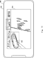
- FIG. 16 and 17 are diagrams showing examples of display screens displayed on the user terminal 200 according to the fourth embodiment.
- FIG. 16 shows a video image for the second user in which a superimposed image 600 indicating biological information of the designated laser is superimposed on the video image 502 of the on-board camera 330 attached to the designated laser.
- the superimposed image 600 in this figure shows how high the heart rate of the designated laser is. As a result, the user can easily grasp the current state of the designated racer and feel more realistic about the race.
- the image for the second user includes a superimposed image 601 indicating the speed of the designated racer, showing the current state of the designated racer in more detail.
- FIG. 17 shows a video for the second user in which a superimposed image 602 indicating the position information of the designated laser is superimposed on the video 504 of the drone camera 320 in which the designated laser is captured.
- a superimposed image 602 in this figure indicates where on the track the designated racer is running. Note that the superimposed image 602 may further indicate the position of the leading laser. As a result, the user can easily grasp the situation of the entire race while confirming the state of the designated racer on the video.
- the hardware configuration is described, but it is not limited to this.
- the present disclosure can also implement arbitrary processing by causing a processor to execute a computer program.
- the program includes instructions (or software code) that, when read into a computer, cause the computer to perform one or more of the functions described in the embodiments.
- the program may be stored in a non-transitory computer-readable medium or tangible storage medium.
- computer readable media or tangible storage media may include random-access memory (RAM), read-only memory (ROM), flash memory, solid-state drives (SSD) or other memory technology, CDs - ROM, digital versatile disc (DVD), Blu-ray disc or other optical disc storage, magnetic cassette, magnetic tape, magnetic disc storage or other magnetic storage device.
- the program may be transmitted on a transitory computer-readable medium or communication medium.
- transitory computer readable media or communication media include electrical, optical, acoustic, or other forms of propagated signals.
- the image providing apparatus 100b may generate distribution data for user images using biological information from the biological information measuring device 400 attached to the body of each racer.
- the biological information measuring device 400 is attached to the body of the horse, but instead of or in addition to this, it may be attached to the body of the jockey to measure the biological information of the jockey.
- the image providing device 100b may generate the distribution data of the user image using the biometric information of each jockey.
- the racer is a boat racer
- a measuring instrument used by the racer to measure the condition of the boat may be attached to the boat.
- the image providing device 100b may acquire the state of the ship used by the designated racer and superimpose a superimposed image showing the state of the ship on the first user image, thereby generating distribution data of the user image.
- (Appendix 2) further comprising priority setting means for setting the priority of each of the plurality of cameras;
- the image providing apparatus according to appendix 1, wherein the generating means generates the user image based on the priority.
- (Appendix 3) The image according to appendix 2, wherein the priority setting means sets the priority of each of the plurality of cameras based on the degree of association between the image collected from each of the plurality of cameras and the laser ID. delivery device.
- the priority setting means sets the priority of each of the plurality of cameras based on at least one of the position information of the laser having the laser ID and the elapsed time from the start of the race. Video providing device. (Appendix 5) 5.
- the generating means selects one or more images to be displayed on the display means of the user terminal from the images collected from the plurality of cameras, based on the priority.
- video providing device (Appendix 6) 6.
- the generating means is generating a first user image from images collected from the plurality of cameras based on the user-designated laser ID; generating a superimposed image showing the state of the laser based on the position information of the laser having the laser ID specified by the user or the biological information of the laser; generating a video for a second user by superimposing the superimposed image on the video for the first user; 7.
- the video providing device according to any one of additional notes 1 to 6, wherein the output control means causes the user terminal to output the video for the second user.
- (Appendix 8) a video providing device; a user terminal used by a user, and the video providing device comprising: Designating means for acquiring a racer ID for identifying a racer designated by the user among the racers participating in the race; video collecting means for collecting videos related to the race captured in the same time interval from each of a plurality of cameras; generating means for generating a user image from images collected from the plurality of cameras based on the laser ID designated by the user; and output control means for outputting the user video to the user terminal.
- (Appendix 9) Acquiring a racer ID for identifying a racer designated by a user among the racers participating in the race; collecting images of the race taken during the same time interval from each of a plurality of cameras; generating a user image from images collected from the plurality of cameras based on the laser ID specified by the user;
- a video providing method comprising outputting the video for the user to a user terminal used by the user.
- a non-temporary computer-readable medium storing a program for causing a computer to execute an output control process for outputting the user video to a user terminal used by the user.
- Reference Signs List 10 100, 100a, 100b Image providing device 11, 141 Designating unit 12 Image collecting unit 142 Image collecting unit 15, 145, 145b Generation unit 16, 146 Output control unit 110, 110a, 110b Storage unit 111, 111a, 111b Program 112 User database 1121 User ID 1122 Racer ID 113 Racer DB 1131 Racer ID 1132 Feature information 114 Camera DB 1141 Camera ID 1142 camerawork type 1143 position information 1144 video data 115 camerawork priority rule 120 memory 130 communication unit 140, 140a, 140b control unit 143 relevance calculation unit 144 priority setting unit 144a priority setting unit 200 user terminal 220 storage unit 230 communication Section 240 Display Section 245 Audio Output Section 250 Input Section 260 Control Section 310 Fixed Camera 320 Drone Camera 330 Onboard Camera 400 Biological Information Measuring Instrument 410 Position Information Measuring Instrument 501, 502, 503, 504 Video 600, 601 Superimposed Image 1000, 1000b Video providing system N network
Landscapes
- Engineering & Computer Science (AREA)
- Physics & Mathematics (AREA)
- General Physics & Mathematics (AREA)
- Multimedia (AREA)
- Theoretical Computer Science (AREA)
- Signal Processing (AREA)
- Computational Linguistics (AREA)
- Software Systems (AREA)
- Closed-Circuit Television Systems (AREA)
- Two-Way Televisions, Distribution Of Moving Picture Or The Like (AREA)
Priority Applications (3)
| Application Number | Priority Date | Filing Date | Title |
|---|---|---|---|
| JP2023534455A JP7517612B2 (ja) | 2021-07-12 | 2021-07-12 | 映像提供装置、映像提供システム、映像提供方法及びプログラム |
| PCT/JP2021/026174 WO2023286133A1 (ja) | 2021-07-12 | 2021-07-12 | 映像提供装置、映像提供システム、映像提供方法及び非一時的なコンピュータ可読媒体 |
| US18/272,910 US12361766B2 (en) | 2021-07-12 | 2021-07-12 | Video provision apparatus, video provision method, and non-transitory computer-readable medium |
Applications Claiming Priority (1)
| Application Number | Priority Date | Filing Date | Title |
|---|---|---|---|
| PCT/JP2021/026174 WO2023286133A1 (ja) | 2021-07-12 | 2021-07-12 | 映像提供装置、映像提供システム、映像提供方法及び非一時的なコンピュータ可読媒体 |
Publications (1)
| Publication Number | Publication Date |
|---|---|
| WO2023286133A1 true WO2023286133A1 (ja) | 2023-01-19 |
Family
ID=84919109
Family Applications (1)
| Application Number | Title | Priority Date | Filing Date |
|---|---|---|---|
| PCT/JP2021/026174 Ceased WO2023286133A1 (ja) | 2021-07-12 | 2021-07-12 | 映像提供装置、映像提供システム、映像提供方法及び非一時的なコンピュータ可読媒体 |
Country Status (3)
| Country | Link |
|---|---|
| US (1) | US12361766B2 (https=) |
| JP (1) | JP7517612B2 (https=) |
| WO (1) | WO2023286133A1 (https=) |
Families Citing this family (1)
| Publication number | Priority date | Publication date | Assignee | Title |
|---|---|---|---|---|
| US20240146706A1 (en) * | 2022-11-02 | 2024-05-02 | Comcast Cable Communications, Llc | Systems and Methods for Service Entitlement Authorization |
Citations (8)
| Publication number | Priority date | Publication date | Assignee | Title |
|---|---|---|---|---|
| JPH09233458A (ja) * | 1996-02-28 | 1997-09-05 | Toshiba Corp | 画像選択方法および画像選択装置 |
| JP2004192632A (ja) * | 2002-11-26 | 2004-07-08 | Seiko Instruments Inc | 競技観覧システム |
| JP2007158860A (ja) * | 2005-12-06 | 2007-06-21 | Canon Inc | 撮影システム、撮影装置、画像切替装置、およびデータ保持装置 |
| WO2014024475A1 (ja) * | 2012-08-10 | 2014-02-13 | パナソニック株式会社 | 映像提供方法、送信装置および受信装置 |
| JP2018025734A (ja) * | 2016-08-03 | 2018-02-15 | 由希子 岡 | 画像表示システムおよび画像表示プログラム |
| JP2018081515A (ja) * | 2016-11-17 | 2018-05-24 | 日本電信電話株式会社 | リソース検索装置およびリソース検索方法 |
| JP2018098573A (ja) * | 2016-12-09 | 2018-06-21 | セイコーエプソン株式会社 | データ収集装置、映像生成装置、映像配信システム、プログラム及び記録媒体 |
| US20190089996A1 (en) * | 2017-09-15 | 2019-03-21 | Cisco Technology, Inc. | Virtualized and automated real time video production system |
Family Cites Families (4)
| Publication number | Priority date | Publication date | Assignee | Title |
|---|---|---|---|---|
| JP2004064511A (ja) | 2002-07-30 | 2004-02-26 | Suzuka Circuitland Co Ltd | レース中継システム |
| JP6598334B2 (ja) | 2018-10-29 | 2019-10-30 | みこらった株式会社 | スポーツ競技ライブ観戦システム、スポーツ競技ライブ観戦システムの映像収集配信設備装置及び観戦者端末 |
| WO2020095647A1 (ja) * | 2018-11-07 | 2020-05-14 | キヤノン株式会社 | 画像処理装置、画像処理サーバー、画像処理方法、コンピュータプログラム及び記憶媒体 |
| JP7323355B2 (ja) | 2019-06-28 | 2023-08-08 | 株式会社Nttドコモ | 情報処理装置 |
-
2021
- 2021-07-12 WO PCT/JP2021/026174 patent/WO2023286133A1/ja not_active Ceased
- 2021-07-12 JP JP2023534455A patent/JP7517612B2/ja active Active
- 2021-07-12 US US18/272,910 patent/US12361766B2/en active Active
Patent Citations (8)
| Publication number | Priority date | Publication date | Assignee | Title |
|---|---|---|---|---|
| JPH09233458A (ja) * | 1996-02-28 | 1997-09-05 | Toshiba Corp | 画像選択方法および画像選択装置 |
| JP2004192632A (ja) * | 2002-11-26 | 2004-07-08 | Seiko Instruments Inc | 競技観覧システム |
| JP2007158860A (ja) * | 2005-12-06 | 2007-06-21 | Canon Inc | 撮影システム、撮影装置、画像切替装置、およびデータ保持装置 |
| WO2014024475A1 (ja) * | 2012-08-10 | 2014-02-13 | パナソニック株式会社 | 映像提供方法、送信装置および受信装置 |
| JP2018025734A (ja) * | 2016-08-03 | 2018-02-15 | 由希子 岡 | 画像表示システムおよび画像表示プログラム |
| JP2018081515A (ja) * | 2016-11-17 | 2018-05-24 | 日本電信電話株式会社 | リソース検索装置およびリソース検索方法 |
| JP2018098573A (ja) * | 2016-12-09 | 2018-06-21 | セイコーエプソン株式会社 | データ収集装置、映像生成装置、映像配信システム、プログラム及び記録媒体 |
| US20190089996A1 (en) * | 2017-09-15 | 2019-03-21 | Cisco Technology, Inc. | Virtualized and automated real time video production system |
Also Published As
| Publication number | Publication date |
|---|---|
| JP7517612B2 (ja) | 2024-07-17 |
| US12361766B2 (en) | 2025-07-15 |
| JPWO2023286133A1 (https=) | 2023-01-19 |
| US20240087369A1 (en) | 2024-03-14 |
Similar Documents
| Publication | Publication Date | Title |
|---|---|---|
| US12076642B2 (en) | Delivery of spectator feedback content to virtual reality environments provided by head mounted display | |
| US20220256120A1 (en) | Image-stream windowing system and method | |
| US10771760B2 (en) | Information processing device, control method of information processing device, and storage medium | |
| JPWO2018199115A1 (ja) | 演出制御装置、演出システム、及びプログラム | |
| EP4050470B1 (en) | Video playback method, medium, glasses and program product | |
| CN112533003A (zh) | 一种视频处理系统、装置、方法 | |
| AU2014271318B2 (en) | Autonomous systems and methods for still and moving picture production | |
| TWI291887B (https=) | ||
| JP6385543B1 (ja) | サーバ装置、配信システム、配信方法及びプログラム | |
| JP7517612B2 (ja) | 映像提供装置、映像提供システム、映像提供方法及びプログラム | |
| JP6848036B1 (ja) | 情報提供装置、情報提供方法、ならびに、プログラム | |
| KR102171356B1 (ko) | 대회 일정과 연동되는 경기영상 스트리밍 방법 및 장치 | |
| EP4050402A1 (en) | Information prompt display method, apparatus, computer readable medium, program product and smart glasses | |
| JP7526955B2 (ja) | 観客分析装置、観客分析方法、及び、コンピュータプログラム | |
| CN114981760A (zh) | 信息处理设备、信息处理终端和程序 | |
| JP7609252B2 (ja) | 画像生成装置、画像生成方法、プログラム | |
| WO2022102550A1 (ja) | 情報処理装置及び情報処理方法 | |
| WO2025154220A1 (ja) | 情報処理システムおよびゲーム画像共有方法 | |
| JP2021159307A (ja) | 情報処理システム、情報処理方法、及びプログラム | |
| JP7258603B2 (ja) | 人物による所定の動作を検証するためのシステム、方法、プログラム、及び装置 | |
| JP2023064585A (ja) | 情報処理装置、情報処理方法およびゲーム実況配信システム | |
| NL1039228C2 (en) | Method and system for capturing, generating and sharing activity data. | |
| CN113992865A (zh) | 超高清转播现场的氛围烘托方法、装置及系统 | |
| WO2021199628A1 (ja) | 情報処理システム、情報処理方法、及びプログラム | |
| CN114930274A (zh) | 信息处理设备、信息处理终端和程序 |
Legal Events
| Date | Code | Title | Description |
|---|---|---|---|
| 121 | Ep: the epo has been informed by wipo that ep was designated in this application |
Ref document number: 21950076 Country of ref document: EP Kind code of ref document: A1 |
|
| ENP | Entry into the national phase |
Ref document number: 2023534455 Country of ref document: JP Kind code of ref document: A |
|
| WWE | Wipo information: entry into national phase |
Ref document number: 18272910 Country of ref document: US |
|
| NENP | Non-entry into the national phase |
Ref country code: DE |
|
| 122 | Ep: pct application non-entry in european phase |
Ref document number: 21950076 Country of ref document: EP Kind code of ref document: A1 |
|
| WWG | Wipo information: grant in national office |
Ref document number: 18272910 Country of ref document: US |