WO2023282071A1 - 無方向性電磁鋼板とその製造方法 - Google Patents
無方向性電磁鋼板とその製造方法 Download PDFInfo
- Publication number
- WO2023282071A1 WO2023282071A1 PCT/JP2022/025040 JP2022025040W WO2023282071A1 WO 2023282071 A1 WO2023282071 A1 WO 2023282071A1 JP 2022025040 W JP2022025040 W JP 2022025040W WO 2023282071 A1 WO2023282071 A1 WO 2023282071A1
- Authority
- WO
- WIPO (PCT)
- Prior art keywords
- mass
- steel sheet
- oriented electrical
- annealing
- electrical steel
- Prior art date
- Legal status (The legal status is an assumption and is not a legal conclusion. Google has not performed a legal analysis and makes no representation as to the accuracy of the status listed.)
- Ceased
Links
Images

Classifications
-
- C—CHEMISTRY; METALLURGY
- C22—METALLURGY; FERROUS OR NON-FERROUS ALLOYS; TREATMENT OF ALLOYS OR NON-FERROUS METALS
- C22C—ALLOYS
- C22C38/00—Ferrous alloys, e.g. steel alloys
- C22C38/02—Ferrous alloys, e.g. steel alloys containing silicon
-
- C—CHEMISTRY; METALLURGY
- C22—METALLURGY; FERROUS OR NON-FERROUS ALLOYS; TREATMENT OF ALLOYS OR NON-FERROUS METALS
- C22C—ALLOYS
- C22C38/00—Ferrous alloys, e.g. steel alloys
- C22C38/18—Ferrous alloys, e.g. steel alloys containing chromium
- C22C38/34—Ferrous alloys, e.g. steel alloys containing chromium with more than 1.5% by weight of silicon
-
- C—CHEMISTRY; METALLURGY
- C21—METALLURGY OF IRON
- C21D—MODIFYING THE PHYSICAL STRUCTURE OF FERROUS METALS; GENERAL DEVICES FOR HEAT TREATMENT OF FERROUS OR NON-FERROUS METALS OR ALLOYS; MAKING METAL MALLEABLE, e.g. BY DECARBURISATION OR TEMPERING
- C21D1/00—General methods or devices for heat treatment, e.g. annealing, hardening, quenching or tempering
- C21D1/26—Methods of annealing
-
- C—CHEMISTRY; METALLURGY
- C21—METALLURGY OF IRON
- C21D—MODIFYING THE PHYSICAL STRUCTURE OF FERROUS METALS; GENERAL DEVICES FOR HEAT TREATMENT OF FERROUS OR NON-FERROUS METALS OR ALLOYS; MAKING METAL MALLEABLE, e.g. BY DECARBURISATION OR TEMPERING
- C21D6/00—Heat treatment of ferrous alloys
- C21D6/008—Heat treatment of ferrous alloys containing Si
-
- C—CHEMISTRY; METALLURGY
- C21—METALLURGY OF IRON
- C21D—MODIFYING THE PHYSICAL STRUCTURE OF FERROUS METALS; GENERAL DEVICES FOR HEAT TREATMENT OF FERROUS OR NON-FERROUS METALS OR ALLOYS; MAKING METAL MALLEABLE, e.g. BY DECARBURISATION OR TEMPERING
- C21D8/00—Modifying the physical properties of ferrous metals or ferrous alloys by deformation combined with, or followed by, heat treatment
- C21D8/12—Modifying the physical properties of ferrous metals or ferrous alloys by deformation combined with, or followed by, heat treatment during manufacturing of articles with special electromagnetic properties
- C21D8/1216—Modifying the physical properties of ferrous metals or ferrous alloys by deformation combined with, or followed by, heat treatment during manufacturing of articles with special electromagnetic properties characterised by the working steps
- C21D8/1222—Hot rolling
-
- C—CHEMISTRY; METALLURGY
- C21—METALLURGY OF IRON
- C21D—MODIFYING THE PHYSICAL STRUCTURE OF FERROUS METALS; GENERAL DEVICES FOR HEAT TREATMENT OF FERROUS OR NON-FERROUS METALS OR ALLOYS; MAKING METAL MALLEABLE, e.g. BY DECARBURISATION OR TEMPERING
- C21D8/00—Modifying the physical properties of ferrous metals or ferrous alloys by deformation combined with, or followed by, heat treatment
- C21D8/12—Modifying the physical properties of ferrous metals or ferrous alloys by deformation combined with, or followed by, heat treatment during manufacturing of articles with special electromagnetic properties
- C21D8/1216—Modifying the physical properties of ferrous metals or ferrous alloys by deformation combined with, or followed by, heat treatment during manufacturing of articles with special electromagnetic properties characterised by the working steps
- C21D8/1233—Cold rolling
-
- C—CHEMISTRY; METALLURGY
- C21—METALLURGY OF IRON
- C21D—MODIFYING THE PHYSICAL STRUCTURE OF FERROUS METALS; GENERAL DEVICES FOR HEAT TREATMENT OF FERROUS OR NON-FERROUS METALS OR ALLOYS; MAKING METAL MALLEABLE, e.g. BY DECARBURISATION OR TEMPERING
- C21D8/00—Modifying the physical properties of ferrous metals or ferrous alloys by deformation combined with, or followed by, heat treatment
- C21D8/12—Modifying the physical properties of ferrous metals or ferrous alloys by deformation combined with, or followed by, heat treatment during manufacturing of articles with special electromagnetic properties
- C21D8/1244—Modifying the physical properties of ferrous metals or ferrous alloys by deformation combined with, or followed by, heat treatment during manufacturing of articles with special electromagnetic properties characterised by the heat treatment
- C21D8/125—Modifying the physical properties of ferrous metals or ferrous alloys by deformation combined with, or followed by, heat treatment during manufacturing of articles with special electromagnetic properties characterised by the heat treatment with application of tension
-
- C—CHEMISTRY; METALLURGY
- C21—METALLURGY OF IRON
- C21D—MODIFYING THE PHYSICAL STRUCTURE OF FERROUS METALS; GENERAL DEVICES FOR HEAT TREATMENT OF FERROUS OR NON-FERROUS METALS OR ALLOYS; MAKING METAL MALLEABLE, e.g. BY DECARBURISATION OR TEMPERING
- C21D8/00—Modifying the physical properties of ferrous metals or ferrous alloys by deformation combined with, or followed by, heat treatment
- C21D8/12—Modifying the physical properties of ferrous metals or ferrous alloys by deformation combined with, or followed by, heat treatment during manufacturing of articles with special electromagnetic properties
- C21D8/1244—Modifying the physical properties of ferrous metals or ferrous alloys by deformation combined with, or followed by, heat treatment during manufacturing of articles with special electromagnetic properties characterised by the heat treatment
- C21D8/1261—Modifying the physical properties of ferrous metals or ferrous alloys by deformation combined with, or followed by, heat treatment during manufacturing of articles with special electromagnetic properties characterised by the heat treatment following hot rolling
-
- C—CHEMISTRY; METALLURGY
- C21—METALLURGY OF IRON
- C21D—MODIFYING THE PHYSICAL STRUCTURE OF FERROUS METALS; GENERAL DEVICES FOR HEAT TREATMENT OF FERROUS OR NON-FERROUS METALS OR ALLOYS; MAKING METAL MALLEABLE, e.g. BY DECARBURISATION OR TEMPERING
- C21D8/00—Modifying the physical properties of ferrous metals or ferrous alloys by deformation combined with, or followed by, heat treatment
- C21D8/12—Modifying the physical properties of ferrous metals or ferrous alloys by deformation combined with, or followed by, heat treatment during manufacturing of articles with special electromagnetic properties
- C21D8/1244—Modifying the physical properties of ferrous metals or ferrous alloys by deformation combined with, or followed by, heat treatment during manufacturing of articles with special electromagnetic properties characterised by the heat treatment
- C21D8/1272—Final recrystallisation annealing
-
- C—CHEMISTRY; METALLURGY
- C21—METALLURGY OF IRON
- C21D—MODIFYING THE PHYSICAL STRUCTURE OF FERROUS METALS; GENERAL DEVICES FOR HEAT TREATMENT OF FERROUS OR NON-FERROUS METALS OR ALLOYS; MAKING METAL MALLEABLE, e.g. BY DECARBURISATION OR TEMPERING
- C21D9/00—Heat treatment, e.g. annealing, hardening, quenching or tempering, adapted for particular articles; Furnaces therefor
- C21D9/46—Heat treatment, e.g. annealing, hardening, quenching or tempering, adapted for particular articles; Furnaces therefor for sheet metals
-
- C—CHEMISTRY; METALLURGY
- C22—METALLURGY; FERROUS OR NON-FERROUS ALLOYS; TREATMENT OF ALLOYS OR NON-FERROUS METALS
- C22C—ALLOYS
- C22C38/00—Ferrous alloys, e.g. steel alloys
- C22C38/001—Ferrous alloys, e.g. steel alloys containing N
-
- C—CHEMISTRY; METALLURGY
- C22—METALLURGY; FERROUS OR NON-FERROUS ALLOYS; TREATMENT OF ALLOYS OR NON-FERROUS METALS
- C22C—ALLOYS
- C22C38/00—Ferrous alloys, e.g. steel alloys
- C22C38/002—Ferrous alloys, e.g. steel alloys containing In, Mg, or other elements not provided for in one single group C22C38/001 - C22C38/60
-
- C—CHEMISTRY; METALLURGY
- C22—METALLURGY; FERROUS OR NON-FERROUS ALLOYS; TREATMENT OF ALLOYS OR NON-FERROUS METALS
- C22C—ALLOYS
- C22C38/00—Ferrous alloys, e.g. steel alloys
- C22C38/004—Very low carbon steels, i.e. having a carbon content of less than 0,01%
-
- C—CHEMISTRY; METALLURGY
- C22—METALLURGY; FERROUS OR NON-FERROUS ALLOYS; TREATMENT OF ALLOYS OR NON-FERROUS METALS
- C22C—ALLOYS
- C22C38/00—Ferrous alloys, e.g. steel alloys
- C22C38/005—Ferrous alloys, e.g. steel alloys containing rare earths, i.e. Sc, Y, Lanthanides
-
- C—CHEMISTRY; METALLURGY
- C22—METALLURGY; FERROUS OR NON-FERROUS ALLOYS; TREATMENT OF ALLOYS OR NON-FERROUS METALS
- C22C—ALLOYS
- C22C38/00—Ferrous alloys, e.g. steel alloys
- C22C38/008—Ferrous alloys, e.g. steel alloys containing tin
-
- C—CHEMISTRY; METALLURGY
- C22—METALLURGY; FERROUS OR NON-FERROUS ALLOYS; TREATMENT OF ALLOYS OR NON-FERROUS METALS
- C22C—ALLOYS
- C22C38/00—Ferrous alloys, e.g. steel alloys
- C22C38/04—Ferrous alloys, e.g. steel alloys containing manganese
-
- C—CHEMISTRY; METALLURGY
- C22—METALLURGY; FERROUS OR NON-FERROUS ALLOYS; TREATMENT OF ALLOYS OR NON-FERROUS METALS
- C22C—ALLOYS
- C22C38/00—Ferrous alloys, e.g. steel alloys
- C22C38/06—Ferrous alloys, e.g. steel alloys containing aluminium
-
- C—CHEMISTRY; METALLURGY
- C22—METALLURGY; FERROUS OR NON-FERROUS ALLOYS; TREATMENT OF ALLOYS OR NON-FERROUS METALS
- C22C—ALLOYS
- C22C38/00—Ferrous alloys, e.g. steel alloys
- C22C38/08—Ferrous alloys, e.g. steel alloys containing nickel
-
- C—CHEMISTRY; METALLURGY
- C22—METALLURGY; FERROUS OR NON-FERROUS ALLOYS; TREATMENT OF ALLOYS OR NON-FERROUS METALS
- C22C—ALLOYS
- C22C38/00—Ferrous alloys, e.g. steel alloys
- C22C38/12—Ferrous alloys, e.g. steel alloys containing tungsten, tantalum, molybdenum, vanadium, or niobium
-
- C—CHEMISTRY; METALLURGY
- C22—METALLURGY; FERROUS OR NON-FERROUS ALLOYS; TREATMENT OF ALLOYS OR NON-FERROUS METALS
- C22C—ALLOYS
- C22C38/00—Ferrous alloys, e.g. steel alloys
- C22C38/14—Ferrous alloys, e.g. steel alloys containing titanium or zirconium
-
- C—CHEMISTRY; METALLURGY
- C22—METALLURGY; FERROUS OR NON-FERROUS ALLOYS; TREATMENT OF ALLOYS OR NON-FERROUS METALS
- C22C—ALLOYS
- C22C38/00—Ferrous alloys, e.g. steel alloys
- C22C38/16—Ferrous alloys, e.g. steel alloys containing copper
-
- C—CHEMISTRY; METALLURGY
- C22—METALLURGY; FERROUS OR NON-FERROUS ALLOYS; TREATMENT OF ALLOYS OR NON-FERROUS METALS
- C22C—ALLOYS
- C22C38/00—Ferrous alloys, e.g. steel alloys
- C22C38/18—Ferrous alloys, e.g. steel alloys containing chromium
-
- C—CHEMISTRY; METALLURGY
- C22—METALLURGY; FERROUS OR NON-FERROUS ALLOYS; TREATMENT OF ALLOYS OR NON-FERROUS METALS
- C22C—ALLOYS
- C22C38/00—Ferrous alloys, e.g. steel alloys
- C22C38/18—Ferrous alloys, e.g. steel alloys containing chromium
- C22C38/32—Ferrous alloys, e.g. steel alloys containing chromium with boron
-
- C—CHEMISTRY; METALLURGY
- C22—METALLURGY; FERROUS OR NON-FERROUS ALLOYS; TREATMENT OF ALLOYS OR NON-FERROUS METALS
- C22C—ALLOYS
- C22C38/00—Ferrous alloys, e.g. steel alloys
- C22C38/18—Ferrous alloys, e.g. steel alloys containing chromium
- C22C38/38—Ferrous alloys, e.g. steel alloys containing chromium with more than 1.5% by weight of manganese
-
- C—CHEMISTRY; METALLURGY
- C22—METALLURGY; FERROUS OR NON-FERROUS ALLOYS; TREATMENT OF ALLOYS OR NON-FERROUS METALS
- C22C—ALLOYS
- C22C38/00—Ferrous alloys, e.g. steel alloys
- C22C38/60—Ferrous alloys, e.g. steel alloys containing lead, selenium, tellurium, or antimony, or more than 0.04% by weight of sulfur
-
- H—ELECTRICITY
- H01—ELECTRIC ELEMENTS
- H01F—MAGNETS; INDUCTANCES; TRANSFORMERS; SELECTION OF MATERIALS FOR THEIR MAGNETIC PROPERTIES
- H01F1/00—Magnets or magnetic bodies characterised by the magnetic materials therefor; Selection of materials for their magnetic properties
- H01F1/01—Magnets or magnetic bodies characterised by the magnetic materials therefor; Selection of materials for their magnetic properties of inorganic materials
- H01F1/03—Magnets or magnetic bodies characterised by the magnetic materials therefor; Selection of materials for their magnetic properties of inorganic materials characterised by their coercivity
- H01F1/12—Magnets or magnetic bodies characterised by the magnetic materials therefor; Selection of materials for their magnetic properties of inorganic materials characterised by their coercivity of soft-magnetic materials
- H01F1/14—Magnets or magnetic bodies characterised by the magnetic materials therefor; Selection of materials for their magnetic properties of inorganic materials characterised by their coercivity of soft-magnetic materials metals or alloys
- H01F1/147—Alloys characterised by their composition
- H01F1/14766—Fe-Si based alloys
- H01F1/14775—Fe-Si based alloys in the form of sheets
-
- H—ELECTRICITY
- H01—ELECTRIC ELEMENTS
- H01F—MAGNETS; INDUCTANCES; TRANSFORMERS; SELECTION OF MATERIALS FOR THEIR MAGNETIC PROPERTIES
- H01F1/00—Magnets or magnetic bodies characterised by the magnetic materials therefor; Selection of materials for their magnetic properties
- H01F1/01—Magnets or magnetic bodies characterised by the magnetic materials therefor; Selection of materials for their magnetic properties of inorganic materials
- H01F1/03—Magnets or magnetic bodies characterised by the magnetic materials therefor; Selection of materials for their magnetic properties of inorganic materials characterised by their coercivity
- H01F1/12—Magnets or magnetic bodies characterised by the magnetic materials therefor; Selection of materials for their magnetic properties of inorganic materials characterised by their coercivity of soft-magnetic materials
- H01F1/14—Magnets or magnetic bodies characterised by the magnetic materials therefor; Selection of materials for their magnetic properties of inorganic materials characterised by their coercivity of soft-magnetic materials metals or alloys
- H01F1/16—Magnets or magnetic bodies characterised by the magnetic materials therefor; Selection of materials for their magnetic properties of inorganic materials characterised by their coercivity of soft-magnetic materials metals or alloys in the form of sheets
-
- C—CHEMISTRY; METALLURGY
- C21—METALLURGY OF IRON
- C21D—MODIFYING THE PHYSICAL STRUCTURE OF FERROUS METALS; GENERAL DEVICES FOR HEAT TREATMENT OF FERROUS OR NON-FERROUS METALS OR ALLOYS; MAKING METAL MALLEABLE, e.g. BY DECARBURISATION OR TEMPERING
- C21D2211/00—Microstructure comprising significant phases
- C21D2211/005—Ferrite
-
- Y—GENERAL TAGGING OF NEW TECHNOLOGICAL DEVELOPMENTS; GENERAL TAGGING OF CROSS-SECTIONAL TECHNOLOGIES SPANNING OVER SEVERAL SECTIONS OF THE IPC; TECHNICAL SUBJECTS COVERED BY FORMER USPC CROSS-REFERENCE ART COLLECTIONS [XRACs] AND DIGESTS
- Y02—TECHNOLOGIES OR APPLICATIONS FOR MITIGATION OR ADAPTATION AGAINST CLIMATE CHANGE
- Y02P—CLIMATE CHANGE MITIGATION TECHNOLOGIES IN THE PRODUCTION OR PROCESSING OF GOODS
- Y02P10/00—Technologies related to metal processing
- Y02P10/20—Recycling
-
- Y—GENERAL TAGGING OF NEW TECHNOLOGICAL DEVELOPMENTS; GENERAL TAGGING OF CROSS-SECTIONAL TECHNOLOGIES SPANNING OVER SEVERAL SECTIONS OF THE IPC; TECHNICAL SUBJECTS COVERED BY FORMER USPC CROSS-REFERENCE ART COLLECTIONS [XRACs] AND DIGESTS
- Y02—TECHNOLOGIES OR APPLICATIONS FOR MITIGATION OR ADAPTATION AGAINST CLIMATE CHANGE
- Y02T—CLIMATE CHANGE MITIGATION TECHNOLOGIES RELATED TO TRANSPORTATION
- Y02T10/00—Road transport of goods or passengers
- Y02T10/60—Other road transportation technologies with climate change mitigation effect
- Y02T10/64—Electric machine technologies in electromobility
Definitions
- the present invention relates to a non-oriented electrical steel sheet with high strength and low eddy current loss in a high frequency region and a method for manufacturing the same.
- a non-oriented electrical steel sheet which is a soft magnetic material, is mainly used for the iron core material of the motor.
- the centrifugal force generated in the rotor is proportional to the square of the rotational speed, so in the design of a motor that rotates at high speed, prevention of rotor destruction is a problem to be solved. Therefore, in a motor that rotates at high speed, the strength of the steel sheet, which is the raw material of the rotor, is increased by refining the crystal grains or leaving a non-recrystallized structure.
- the rotor excitation waveform contains harmonics (slot harmonics) of about 1 Hz to 10 kHz due to the motor structure, an increase in iron loss due to these harmonics is also a problem.
- harmonics slot harmonics
- non-oriented electrical steel sheets which are iron core materials, are strongly required not only to have high strength but also to reduce iron loss in the high frequency region.
- the iron loss W of a non-oriented electrical steel sheet is the sum of the hysteresis loss Wh and the eddy current loss We, which are proportional to the first power and the square of the frequency. become dominant.
- Wh hysteresis loss
- We eddy current loss
- Patent Document 1 proposes to adopt warm rolling for cold rolling
- Patent Document 2 proposes to utilize Mn in order to suppress the increase in strength of steel.
- the warm rolling proposed in Patent Document 1 has a problem that if the steel sheet temperature at the start of rolling is too high, the shape of the steel sheet after rolling deteriorates, and there is a limit to its application to industrial production. .
- the method of utilizing Mn proposed in Patent Document 2 requires the addition of a large amount of Mn in order to sufficiently obtain the effect of reducing iron loss. There is a problem that the loss is likely to become unstable.
- the present invention has been made in view of the above-mentioned problems of the prior art, and its object is to reduce eddy current loss in a high frequency region by means other than high alloying, thereby achieving high strength and
- An object of the present invention is to provide a non-oriented electrical steel sheet with low iron loss in a high frequency region and to propose an advantageous manufacturing method thereof.
- the inventors premised on using a technique for leaving a non-recrystallized structure as a means of achieving high strength, and on that basis, steel sheets that are used in grain-oriented electrical steel sheets Focusing on the technology to reduce the core loss by applying a tensile stress to the steel sheet, we have made extensive studies on measures to reduce the eddy current loss of non-oriented electrical steel sheets. As a result, the present inventors have found that eddy current loss in the high frequency range can be reduced even with high strength by controlling the value of residual stress in product steel sheets within an appropriate range, leading to the development of the present invention.
- the present invention based on the above knowledge has an average grain size of ferrite of less than 50 ⁇ m, a yield stress of 500 MPa or more, and a compressive residual stress ⁇ in the width direction at the surface of the steel sheet and the center of the thickness measured by the X-ray stress measurement method.
- the non-oriented electrical steel sheet is characterized in that S 1 and ⁇ C are each 2.0 MPa or more.
- the 2 ⁇ -sin 2 ⁇ method using the ⁇ -Fe (211) peak is used as the X-ray stress measurement method.
- the non-oriented electrical steel sheet of the present invention has C: 0 to 0.0050 mass%, Si: 2.0 to 5.0 mass%, Mn: 0 to 3.0 mass%, P: 0 to 0.2 mass%, S : 0 to 0.0050 mass%, Al: 0 to 3.0 mass%, N: 0 to 0.0050 mass%, Cr: 0 to 3.0 mass% and O: 0 to 0.0050 mass%, the balance being Fe and unavoidable impurities.
- the non-oriented electrical steel sheet of the present invention is characterized by containing at least one group of ingredients among the following groups A to D in addition to the above ingredient composition.
- Group A Sn: 0 to 0.20 mass% and Sb: at least one of 0 to 0.20 mass% Group B; Ca: 0 to 0.01 mass%, Mg: 0 to 0.01 mass% and REM: at least one of 0 to 0.05 mass% Group C; Cu: 0 to 0.5 mass% and Ni: at least one of 0 to 0.5 mass% Group D; Ge: 0 to 0 At least one of 0.05 mass%, As: 0 to 0.05 mass%, and Co: 0 to 0.05 mass%
- the above non-oriented electrical steel sheet of the present invention is characterized by containing at least one group of ingredients from Groups E to I below in addition to the above ingredient composition.
- Group E Ti: 0 to 0.005 mass%, Nb: 0 to 0.005 mass%, V: 0 to 0.010 mass% and Ta: at least one of 0 to 0.002 mass% Group F; B: 0 to 0.002 mass% and Ga: at least one of 0 to 0.005% Group G; Pb: 0 to 0.002 mass% ⁇ H group; Zn: 0 to 0.005 mass% Group I; at least one of Mo: 0 to 0.05 mass% and W: 0 to 0.05 mass%
- the non-oriented electrical steel sheet of the present invention is characterized in that the non-recrystallized structure in the plate thickness cross section parallel to the rolling direction has an area ratio of 1% or more.
- the present invention also provides a method for producing a non-oriented electrical steel sheet, comprising hot-rolling a slab having any one of the chemical compositions described above, annealing the hot-rolled sheet, cold-rolling it, and finish-annealing it in a continuous annealing furnace.
- the maximum temperature of the finish annealing is less than 900°C, and the average cooling rate from the temperature (maximum temperature -50°C) to 500°C in the cooling process of the finish annealing is 40°C/s or more.
- a parameter ⁇ /t defined from the plastic elongation rate ⁇ (%) in the rolling direction before and after the finish annealing and the soaking time t (s) of the finish annealing is set to 0.10 or more.
- a method for producing a non-oriented electrical steel sheet according to any one of 1 to 5 is proposed.
- the present invention it is possible to increase the strength of a non-oriented electrical steel sheet and reduce iron loss in a high frequency range without using means that adversely affect manufacturing costs and productivity, such as high alloying and thinning. . Therefore, by using the non-oriented electrical steel sheet of the present invention for rotor cores such as drive motors for EVs and HEVs, compressor motors for high-efficiency air conditioners, etc., it greatly contributes to high efficiency and miniaturization of motors.
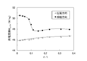
- FIG. 4 is a graph showing the relationship between the ratio ⁇ /t of the plastic elongation rate ⁇ (%) to the soaking time t (s) in the final annealing and the eddy current loss W e3/5k in the rolling direction and width direction of the steel plate. .
- the relationship between the ratio ⁇ /t of the plastic elongation rate ⁇ (%) in the final annealing and the soaking time t (s) and the compressive residual stresses ⁇ S and ⁇ C in the width direction at the steel plate surface and at the center of the thickness are shown. It is a graph showing.
- the maximum temperature is set to 780 ° C.
- soaking is performed by holding in the temperature range from the maximum temperature to (maximum temperature -10 ° C.) for 1 to 30 seconds, and then (maximum temperature -50 ° C.).
- Finish annealing was performed by gas cooling from the temperature to 500°C at an average cooling rate of 50°C/s to obtain a product sheet.
- the plastic elongation rate ⁇ is the elongation rate of the nominal strain.
- the soaking time is defined as the residence time in the temperature range from the maximum temperature to (maximum temperature -10°C).
- the results were analyzed focusing on the eddy current loss We3 /5k at a maximum magnetic flux density of 0.3 T and a frequency of 5 kHz as an index of iron loss increase due to harmonics.
- FIG. 1 shows the parameter ⁇ /t defined from the plastic elongation rate ⁇ (%) and the soaking time t (s) in the final annealing, and the eddy current loss W e3/5k in the rolling direction and width direction of the steel plate. It shows the relationship. From this figure, when ⁇ /t is 0.10 or more, W e3/5k in the rolling direction increases slightly, but W e3/5k in the width direction decreases greatly, and the average of W e3/5k in the rolling direction and width direction It can be seen that the iron loss value is reduced.
- the inventors examined the reason why eddy current loss is reduced by setting ⁇ /t to 0.10 or more as described above. As a result, it was found that the reduction of this eddy current loss has a strong correlation with the residual stress of the product plate.
- the residual stress is a value measured by an X-ray stress measurement method. Specifically, MSF-2M manufactured by Rigaku Corporation was used as an X-ray measurement device.
- the ⁇ angles were 12, 16, 20, 24, 28, 32, 36, 40, 44, and 48°, and the swing angle of ⁇ was in the range of ⁇ 3°.
- the residual stress ⁇ was measured at two points, the surface and the center of the thickness of the test piece. In addition, the measurement of the plate thickness central portion was performed by removing from one surface of the test piece to the central portion by chemical polishing.
- the above residual stress ⁇ is a positive value, it means that there is a compressive residual stress in the material, and conversely, if it is a negative value, it means that there is a tensile residual stress in the material.
- FIG. 2 shows the relationship between the compressive residual stresses ⁇ S and ⁇ C in the sheet width direction at the steel sheet surface and the sheet thickness center obtained by measuring as described above, and the iron loss W e3/5k in the sheet width direction. . From FIG. 2 and FIG. 1 described above, it can be seen that when the compressive residual stress increases, W e3/5k in the plate width direction decreases.
- C 0 to 0.0050 mass%
- C is a component that forms carbides in the product sheet by magnetic aging and deteriorates iron loss. Therefore, in order to suppress the above magnetic aging, C is set in the range of 0 to 0.0050 mass%. It is preferably in the range of 0.0001 to 0.0020 mass%.
- Si 2.0 to 5.0 mass%
- Si has the effect of increasing the resistivity of steel and reducing iron loss. In addition, it also has the effect of increasing the strength of steel through solid-solution strengthening.
- the lower limit of Si is set to 2.0 mass%.
- the upper limit is made 5.0 mass%. It is preferably in the range of 3.5 to 5.0 mass%. The range of 3.5 to 4.5 mass% is preferable from the viewpoint of ensuring a particularly excellent strength/iron loss balance.
- Mn 0-3.0 mass% Mn has the effect of increasing the specific resistance of steel and reducing iron loss. However, when the content exceeds 3.0 mass%, carbonitrides are precipitated and the core loss is rather deteriorated. Therefore, Mn is added in the range of 0 to 3.0 mass%. In order to reliably obtain the iron loss reduction effect, it is preferable to add 0.3 mass % or more, and the upper limit is preferably 2.0 mass from the viewpoint of suppressing the formation of carbonitrides.
- P 0 to 0.2 mass%
- P is a component used for strength adjustment of steel and can be added as appropriate. However, when P exceeds 0.2 mass%, the steel becomes embrittled and rolling becomes difficult. Therefore, the P content should be in the range of 0 to 0.2 mass%. When P is not used for strength adjustment, it is preferably less than 0.02 mass%, while when it is used, it is preferably in the range of 0.02 to 0.10 mass%.
- S 0 to 0.0050 mass%
- S is a harmful component that precipitates fine sulfides to inhibit grain growth and increase iron loss.
- the S content exceeds 0.0050 mass%, the above-mentioned adverse effects become pronounced, so the S content is made in the range of 0 to 0.0050 mass%.
- a preferable upper limit is 0.0020 mass%.
- Al 0 to 3.0 mass%
- Al has the effect of increasing the resistivity of steel and reducing iron loss. In addition, it also has the effect of increasing the strength of steel through solid-solution strengthening.
- the Al content is made in the range of 0 to 3.0 mass%. It is preferably in the range of 1.2 to 3.0 mass%. From the viewpoint of ensuring a particularly excellent strength/iron loss balance, the range of 1.2 to 2.5 mass% is more preferable.
- Al is a component that facilitates the formation of cavities during casting and solidification, so it is preferable to limit Al to 0.01 mass% or less when emphasizing recyclability.
- N 0 to 0.0050 mass%
- N is a harmful component that precipitates fine nitrides to inhibit grain growth and increase iron loss.
- the N content exceeds 0.0050 mass%, the above-mentioned adverse effects become pronounced, so the N content is made in the range of 0 to 0.0050 mass%.
- a preferable upper limit is 0.0020 mass%.
- Cr 0 to 3.0 mass% Cr has the effect of increasing the resistivity of steel and reducing iron loss. However, if the Cr content exceeds 3.0 mass%, precipitation of carbonitrides rather deteriorates the iron loss, so the Cr content is made in the range of 0 to 3.0 mass%. If the Cr content is less than 0.3 mass%, the effect of reducing the iron loss is small. Therefore, when the iron loss is emphasized, the addition of 0.3 mass% or more is preferable. Moreover, from the viewpoint of suppressing the formation of carbonitrides, the upper limit is preferably 2.0 mass%.
- O 0 to 0.0050 mass%
- O is a harmful component that forms oxide-based inclusions, inhibits grain growth, and increases iron loss. Therefore, the O content should be in the range of 0 to 0.0050 mass%. In addition, a preferable upper limit is 0.0020 mass%.
- the non-oriented electrical steel sheet of the present invention may further contain the following components in addition to the components described above, depending on the required properties.
- At least one of Sn: 0 to 0.20 mass% and Sb: 0 to 0.20 mass% Sn and Sb have the effect of improving recrystallization texture and reducing iron loss, and are added as appropriate. can be done. However, even if it is added in excess of 0.20 mass%, the above effect is saturated, so the upper limit of each is preferably 0.20 mass%. More preferably, each is in the range of 0.005 to 0.01 mass%.
- Ca, Mg and REM (rare earth metal) form stable sulfides. Since it reduces fine sulfides, it has the effect of improving grain growth and iron loss. However, excessive addition rather causes an increase in iron loss. Therefore, when they are added, the upper limits of Ca: 0.01 mass%, Mg: 0.010 mass%, and REM: 0.05 mass% are preferable. More preferably, Ca: 0.001 to 0.005 mass%, Mg: 0.0005 to 0.003 mass%, and REM: 0.005 to 0.03 mass%.
- the non-oriented electrical steel sheet of the present invention may further contain the following components within the following ranges. At least one of Cu: 0 to 0.5 mass% and Ni: 0 to 0.5 mass% Cu and Ni are components effective in increasing the toughness of steel, and can be added as appropriate. However, the above effects are saturated even if they are added in excess of 0.5 mass%, so the upper limit of each is preferably 0.5 mass%. More preferably, each is in the range of 0.01 to 0.1 mass%.
- At least one of Ge: 0 to 0.05 mass%, As: 0 to 0.05 mass%, and Co: 0 to 0.05 mass% Ge, As, and Co increase magnetic flux density and reduce core loss. It is an effective component for and can be added as appropriate. However, even if each is added in excess of 0.05 mass%, the above effects are saturated, so the upper limit of each is preferably 0.05 mass%. More preferably, each is in the range of 0.002 to 0.01 mass%.
- the non-oriented electrical steel sheet of the present invention may further contain the following components in the following ranges in addition to the above components.
- Ti, Nb, V and Ta are It is a harmful component that forms fine carbonitrides and increases iron loss, and in particular, if the above upper limit is exceeded, the adverse effects become noticeable. Therefore, Ti, Nb, V and Ta are respectively Ti: 0 to 0.005 mass%, Nb: 0 to 0.005 mass%, V: 0 to 0.010 mass% and Ta: in the range of 0 to 0.002 mass% It is preferably contained. More preferable upper limits are Ti: 0.002 mass%, Nb: 0.002 mass%, V: 0.005 mass% and Ta: 0.001 mass%.
- B 0 to 0.002 mass% and Ga: at least one of 0 to 0.005 mass%
- B and Ga are harmful components that form fine nitrides and increase iron loss. If the value is exceeded, the adverse effects become noticeable. Therefore, B and Ga are preferably added in the ranges of B: 0 to 0.002 mass% and Ga: 0 to 0.005 mass%, respectively. In addition, more preferable upper limit values are B: 0.001 mass% and Ga: 0.002 mass%.
- Pb 0 to 0.002 mass%
- Pb is a harmful component that forms fine Pb particles and increases iron loss. In particular, when it exceeds 0.002 mass%, the above-mentioned adverse effects become noticeable. Therefore, Pb is preferably contained in the range of 0 to 0.002 mass%. In addition, a more preferable upper limit is 0.001 mass%.
- Zn 0 to 0.005 mass%
- Zn is a harmful component that increases fine inclusions and iron loss, and in particular, when it exceeds 0.005 mass%, the above-mentioned adverse effects become remarkable. Therefore, the Zn content is preferably in the range of 0 to 0.005 mass%. In addition, a more preferable upper limit is 0.003 mass%.
- Mo: 0 to 0.05 mass% and W: at least one of 0 to 0.05 mass% Mo and W are harmful components that form fine carbides and increase iron loss. If it is contained in excess, the above-mentioned adverse effects become remarkable. Therefore, it is preferable to contain Mo and W in the ranges of Mo: 0 to 0.05 mass% and W: 0 to 0.05 mass%, respectively. More preferable upper limits are Mo: 0.02 mass% and W: 0.02 mass%.
- the balance other than the above components is substantially Fe and unavoidable impurities.
- the non-oriented electrical steel sheet of the present invention needs to have a yield stress of 500 MPa or more in order to prevent breakage of the motor during high-speed rotation.
- the yield stress is a value obtained by performing a tensile test according to JIS Z 2241 using a JIS No. 5 tensile test piece whose tensile direction is the rolling direction.
- the yield stress is defined as the upper yield point, and when discontinuous yielding is not recognized, the 0.2% proof stress.
- a preferred yield stress is in the range of 600-800 MPa.
- the non-oriented electrical steel sheet of the present invention needs to have an average ferrite grain size of less than 50 ⁇ m. If the grain size of the ferrite is 50 ⁇ m or more, there is a problem of rotor breakage due to a decrease in strength. It is preferably 25 ⁇ m or less.
- the above average grain size is the value of the average grain size measured by the cutting method for the microstructure that is revealed by etching the plate thickness cross section perpendicular to the plate width direction (rolling direction plate thickness cross section) with nital solution or the like. (average line segment length per crystal of test line).
- the non-recrystallized structure in addition to refining the grains, when observing the thickness cross section parallel to the rolling direction, has an area It is preferable that the ratio is 1% or more. More preferably, it is in the range of 10-42%.
- the average grain size of the ferrite when the non-recrystallized structure remains means the average grain size of only recrystallized crystal grains.
- the compressive residual stress ⁇ S in the sheet width direction on the surface of the steel sheet obtained by the X-ray stress measurement method and the thickness It is necessary that the compressive residual stress ⁇ C at the central portion is 2.0 MPa or more.
- the X-ray stress measurement method is the 2 ⁇ -sin 2 ⁇ method using the ⁇ -Fe (211) peak, and the measured compressive stress is calculated from the lattice spacing of the ⁇ 211 ⁇ plane of Fe. value.
- the compressive stress detected here is a value calculated from the lattice spacing of the ⁇ 211 ⁇ plane of Fe, and it is considered that the tensile stress is applied to the magnetization easy axis ⁇ 100> of each crystal grain. . If the value of residual compressive stress exceeds 100 MPa, micro-yielding occurs in some crystal grains, so the upper limit is preferably 100 MPa.
- the residual stress introduced in the present invention must be substantially uniform in the plate thickness direction. This is because the effect of the present invention cannot be obtained if the residual stress fluctuates in the plate thickness direction. For example, when a compressive stress is applied to the surface layer of a steel sheet by shot blasting, a tensile stress is generated at the center of the thickness of the steel sheet, so that the effect of the present invention cannot be obtained.
- the steel material (slab) used for the production of the non-oriented electrical steel sheet of the present invention is prepared by secondary refining such as vacuum degassing of molten steel melted in a converter or an electric furnace to adjust the composition to the above-mentioned composition. After that, it can be manufactured by a continuous casting method or an ingot casting/blooming rolling method.
- the slab is hot-rolled by a known method and conditions to obtain a hot-rolled sheet, hot-rolled sheet annealing is performed as necessary, pickling is performed, and cold rolling or intermediate annealing is performed once.
- a cold-rolled sheet having a final thickness (product thickness) is obtained by cold rolling two or more times.
- the cold-rolled sheet is subjected to final annealing using a continuous annealing furnace in order to impart desired strength and magnetic properties.
- the final annealing conditions be such that the maximum temperature is less than 900° C. and the soaking time is in the range of 1 to 120 seconds. More preferably, the maximum temperature reached is 650 to 850° C., and the soaking time is 5 to 30 seconds.
- the atmosphere during the final annealing is preferably a reducing atmosphere such as a dry H 2 —N 2 mixed atmosphere from the viewpoint of suppressing oxidation.
- the parameter ⁇ /t must be 0.10 or more. If the parameter ⁇ /t is less than 0.10, ⁇ is too small to introduce a sufficient residual stress into the steel sheet, or t is too large and the residual stress disappears due to recovery. A preferable ⁇ /t is 0.15 or more.
- the plastic deformation behavior during finish annealing changes depending on the chemical composition of the steel sheet, finish annealing conditions (annealing temperature, heating time), and line tension. Therefore, in steel sheets containing a large amount of Si and Al, which have high high-temperature strength, ⁇ /t can be increased by increasing the annealing temperature or increasing the line tension.
- the residual stress introduced into the steel sheet in the high temperature range remains until room temperature, so that the temperature (maximum attained temperature -50 ° C.) to 500 ° C. in the cooling process after soaking. It means that the average cooling rate of must be 40° C./s or more. If the average cooling rate in the above temperature range is less than 40° C./s, the residual stress introduced at high temperature is released by recovery, and the effects of the present invention cannot be obtained. It is preferably 50° C./s or more.
- the steel sheet after the finish annealing is coated with an insulating coating to be used as a product sheet.
- an insulating coating to be used as a product sheet.
- Known organic or inorganic or organic+inorganic coatings can be applied to the insulating coating, and none of them impair the effects of the present invention.
- the cold-rolled sheets were subjected to finish annealing under various conditions shown in Table 1 in a continuous annealing furnace. At this time, the plastic elongation rate ⁇ (%) before and after the final annealing was measured by the method described above.
- a test piece having a width of 30 mm and a length of 280 mm was taken from the finish-annealed sheet thus obtained, and the iron loss W 3/5k was measured by the Epstein test.
- the value of the eddy current loss We3 /5k at 0.3 T and 5 kHz was calculated by the method.
- the residual stresses ⁇ S and ⁇ C in the sheet width direction of the finish-annealed sheets were measured by the method described above.
- a JIS No. 5 test piece was sampled from the finish-annealed sheet with the rolling direction as the tensile direction, and a tensile test was performed according to JIS Z 2241 to measure the yield stress.
- the slab was heated to a temperature of 1150° C. for 30 minutes and then hot rolled to obtain a hot-rolled sheet having a thickness of 1.8 mm.
- the hot-rolled sheet was subjected to hot-rolled sheet annealing at 940° C. ⁇ 10 s, pickled, and cold-rolled to obtain a cold-rolled sheet having a final thickness (product thickness) of 0.20 mm.
- the cold-rolled sheet is soaked in a continuous annealing furnace with a maximum temperature of 750 ° C.
- a test piece having a width of 30 mm and a length of 280 mm was taken from the finish-annealed sheet thus obtained, and the iron loss W 3/5k was measured by the Epstein test.
- the value of the eddy current loss We3 /5k at 0.3 T and 5 kHz was calculated by the method.
- the residual stresses ⁇ S and ⁇ C in the sheet width direction of the finish-annealed sheets were measured by the method described above.
- a JIS No. 5 test piece was sampled from the finish-annealed sheet with the rolling direction as the tensile direction, and a tensile test was performed according to JIS Z 2241 to measure the yield stress.
- Table 2 also shows the results of the above measurements.
- W (700 ⁇ t)/(Si+Al)
- t plate thickness (mm)
- Si, Al content of each (mass%)
- W eddy current loss We3/5k
Landscapes
- Chemical & Material Sciences (AREA)
- Engineering & Computer Science (AREA)
- Mechanical Engineering (AREA)
- Organic Chemistry (AREA)
- Metallurgy (AREA)
- Materials Engineering (AREA)
- Physics & Mathematics (AREA)
- Crystallography & Structural Chemistry (AREA)
- Thermal Sciences (AREA)
- Electromagnetism (AREA)
- Manufacturing & Machinery (AREA)
- Dispersion Chemistry (AREA)
- Power Engineering (AREA)
- Soft Magnetic Materials (AREA)
- Manufacturing Of Steel Electrode Plates (AREA)
Priority Applications (6)
| Application Number | Priority Date | Filing Date | Title |
|---|---|---|---|
| JP2022556654A JP7231895B1 (ja) | 2021-07-05 | 2022-06-23 | 無方向性電磁鋼板とその製造方法 |
| US18/571,824 US20240295015A1 (en) | 2021-07-05 | 2022-06-23 | Non-oriented electrical steel sheet and production method thereof |
| KR1020247003476A KR102961099B1 (ko) | 2021-07-05 | 2022-06-23 | 무방향성 전자 강판과 그의 제조 방법 |
| MX2024000338A MX2024000338A (es) | 2021-07-05 | 2022-06-23 | Chapa de acero electrico no orientado y metodo de produccion de la misma. |
| CN202280045184.6A CN117545868A (zh) | 2021-07-05 | 2022-06-23 | 无取向性电磁钢板及其制造方法 |
| EP22837488.0A EP4365318A4 (en) | 2021-07-05 | 2022-06-23 | NON-ORIENTED ELECTROMAGNETIC STEEL SHEET AND METHOD FOR PRODUCING THE SAME |
Applications Claiming Priority (2)
| Application Number | Priority Date | Filing Date | Title |
|---|---|---|---|
| JP2021111433 | 2021-07-05 | ||
| JP2021-111433 | 2021-07-05 |
Publications (1)
| Publication Number | Publication Date |
|---|---|
| WO2023282071A1 true WO2023282071A1 (ja) | 2023-01-12 |
Family
ID=84800285
Family Applications (1)
| Application Number | Title | Priority Date | Filing Date |
|---|---|---|---|
| PCT/JP2022/025040 Ceased WO2023282071A1 (ja) | 2021-07-05 | 2022-06-23 | 無方向性電磁鋼板とその製造方法 |
Country Status (7)
| Country | Link |
|---|---|
| US (1) | US20240295015A1 (https=) |
| EP (1) | EP4365318A4 (https=) |
| JP (1) | JP7231895B1 (https=) |
| CN (1) | CN117545868A (https=) |
| MX (1) | MX2024000338A (https=) |
| TW (1) | TWI850690B (https=) |
| WO (1) | WO2023282071A1 (https=) |
Cited By (3)
| Publication number | Priority date | Publication date | Assignee | Title |
|---|---|---|---|---|
| WO2024210197A1 (ja) * | 2023-04-07 | 2024-10-10 | 日本製鉄株式会社 | 無方向性電磁鋼板、ロータコア、モータ、及び、無方向性電磁鋼板の製造方法 |
| WO2025008095A1 (de) * | 2023-07-04 | 2025-01-09 | Thyssenkrupp Steel Europe Ag | Nicht kornorientiertes metallisches Elektroband oder -blech, Verfahren zur Herstellung eines nicht kornorientierten Elektrobands sowie Verwendung |
| JP2025523697A (ja) * | 2022-07-20 | 2025-07-23 | バオシャン アイアン アンド スティール カンパニー リミテッド | 無方向性電磁鋼板およびその製造方法 |
Citations (6)
| Publication number | Priority date | Publication date | Assignee | Title |
|---|---|---|---|---|
| JPH01219125A (ja) * | 1988-02-26 | 1989-09-01 | Nkk Corp | 鉄損特性及び低磁場での磁束密度の優れた無方向性電磁鋼板の製造方法 |
| JP2008231504A (ja) | 2007-03-20 | 2008-10-02 | Jfe Steel Kk | 無方向性電磁鋼板 |
| JP2009185357A (ja) * | 2008-02-07 | 2009-08-20 | Jfe Steel Corp | 無方向性電磁鋼板およびその製造方法 |
| JP2012036455A (ja) * | 2010-08-09 | 2012-02-23 | Sumitomo Metal Ind Ltd | 無方向性電磁鋼板およびその製造方法 |
| JP2014210978A (ja) | 2012-03-29 | 2014-11-13 | 新日鐵住金株式会社 | 無方向性電磁鋼板およびその製造方法 |
| CN111057821A (zh) * | 2019-12-27 | 2020-04-24 | 首钢智新迁安电磁材料有限公司 | 一种无取向电工钢及其制备方法、应用 |
Family Cites Families (5)
| Publication number | Priority date | Publication date | Assignee | Title |
|---|---|---|---|---|
| KR100479992B1 (ko) * | 1999-09-22 | 2005-03-30 | 주식회사 포스코 | 자성이 우수한 무방향성 전기강판 및 그 제조방법 |
| JP5130637B2 (ja) * | 2006-03-22 | 2013-01-30 | Jfeスチール株式会社 | 高強度無方向性電磁鋼板およびその製造方法 |
| JP6398967B2 (ja) * | 2015-12-25 | 2018-10-03 | Jfeスチール株式会社 | 表面外観及びめっき密着性に優れた高強度溶融めっき熱延鋼板およびその製造方法 |
| TWI658152B (zh) * | 2017-03-07 | 2019-05-01 | 日商新日鐵住金股份有限公司 | 無方向性電磁鋼板及無方向性電磁鋼板之製造方法 |
| KR102278897B1 (ko) * | 2019-12-19 | 2021-07-16 | 주식회사 포스코 | 무방향성 전기강판 및 그 제조방법 |
-
2022
- 2022-06-23 CN CN202280045184.6A patent/CN117545868A/zh active Pending
- 2022-06-23 US US18/571,824 patent/US20240295015A1/en active Pending
- 2022-06-23 MX MX2024000338A patent/MX2024000338A/es unknown
- 2022-06-23 WO PCT/JP2022/025040 patent/WO2023282071A1/ja not_active Ceased
- 2022-06-23 EP EP22837488.0A patent/EP4365318A4/en active Pending
- 2022-06-23 JP JP2022556654A patent/JP7231895B1/ja active Active
- 2022-07-01 TW TW111124658A patent/TWI850690B/zh active
Patent Citations (6)
| Publication number | Priority date | Publication date | Assignee | Title |
|---|---|---|---|---|
| JPH01219125A (ja) * | 1988-02-26 | 1989-09-01 | Nkk Corp | 鉄損特性及び低磁場での磁束密度の優れた無方向性電磁鋼板の製造方法 |
| JP2008231504A (ja) | 2007-03-20 | 2008-10-02 | Jfe Steel Kk | 無方向性電磁鋼板 |
| JP2009185357A (ja) * | 2008-02-07 | 2009-08-20 | Jfe Steel Corp | 無方向性電磁鋼板およびその製造方法 |
| JP2012036455A (ja) * | 2010-08-09 | 2012-02-23 | Sumitomo Metal Ind Ltd | 無方向性電磁鋼板およびその製造方法 |
| JP2014210978A (ja) | 2012-03-29 | 2014-11-13 | 新日鐵住金株式会社 | 無方向性電磁鋼板およびその製造方法 |
| CN111057821A (zh) * | 2019-12-27 | 2020-04-24 | 首钢智新迁安电磁材料有限公司 | 一种无取向电工钢及其制备方法、应用 |
Non-Patent Citations (1)
| Title |
|---|
| See also references of EP4365318A4 |
Cited By (5)
| Publication number | Priority date | Publication date | Assignee | Title |
|---|---|---|---|---|
| JP2025523697A (ja) * | 2022-07-20 | 2025-07-23 | バオシャン アイアン アンド スティール カンパニー リミテッド | 無方向性電磁鋼板およびその製造方法 |
| WO2024210197A1 (ja) * | 2023-04-07 | 2024-10-10 | 日本製鉄株式会社 | 無方向性電磁鋼板、ロータコア、モータ、及び、無方向性電磁鋼板の製造方法 |
| JPWO2024210197A1 (https=) * | 2023-04-07 | 2024-10-10 | ||
| JP7776796B2 (ja) | 2023-04-07 | 2025-11-27 | 日本製鉄株式会社 | 無方向性電磁鋼板、ロータコア、モータ、及び、無方向性電磁鋼板の製造方法 |
| WO2025008095A1 (de) * | 2023-07-04 | 2025-01-09 | Thyssenkrupp Steel Europe Ag | Nicht kornorientiertes metallisches Elektroband oder -blech, Verfahren zur Herstellung eines nicht kornorientierten Elektrobands sowie Verwendung |
Also Published As
| Publication number | Publication date |
|---|---|
| CN117545868A (zh) | 2024-02-09 |
| EP4365318A4 (en) | 2025-01-08 |
| EP4365318A1 (en) | 2024-05-08 |
| US20240295015A1 (en) | 2024-09-05 |
| TW202302877A (zh) | 2023-01-16 |
| JPWO2023282071A1 (https=) | 2023-01-12 |
| KR20240027787A (ko) | 2024-03-04 |
| MX2024000338A (es) | 2024-01-25 |
| TWI850690B (zh) | 2024-08-01 |
| JP7231895B1 (ja) | 2023-03-02 |
Similar Documents
| Publication | Publication Date | Title |
|---|---|---|
| TWI717201B (zh) | 無方向性電磁鋼板及其製造方法 | |
| JP7143900B2 (ja) | 無方向性電磁鋼板 | |
| JP7444275B2 (ja) | 無方向性電磁鋼板とその製造方法 | |
| CN110651058B (zh) | 取向性电磁钢板及其制造方法 | |
| CN111527218B (zh) | 无取向电工钢板及其制造方法 | |
| WO2020262063A1 (ja) | 無方向性電磁鋼板の製造方法とモータコアの製造方法およびモータコア | |
| JP7231895B1 (ja) | 無方向性電磁鋼板とその製造方法 | |
| TW202104614A (zh) | 無方向性電磁鋼板及其製造方法及電動機芯 | |
| TWI829403B (zh) | 無方向性電磁鋼板及其製造方法 | |
| WO2014024222A1 (ja) | 高強度電磁鋼板およびその製造方法 | |
| JPH11310857A (ja) | 無方向性電磁鋼板およびその製造方法 | |
| JP7328597B2 (ja) | 無方向性電磁鋼板およびその製造方法 | |
| WO2024057940A1 (ja) | 高強度無方向性電磁鋼板とその製造方法 | |
| JP6950748B2 (ja) | 無方向性電磁鋼板の製造方法 | |
| JP7736157B2 (ja) | 無方向性電磁鋼板とその製造方法 | |
| TWI890169B (zh) | 無方向性電磁鋼板及其製造方法 | |
| KR102961099B1 (ko) | 무방향성 전자 강판과 그의 제조 방법 | |
| JP7828022B2 (ja) | 無方向性電磁鋼板およびその製造方法 | |
| JP7828027B2 (ja) | 無方向性電磁鋼板およびその製造方法 | |
| RU2859824C2 (ru) | Изотропный лист электротехнической стали и способ его изготовления | |
| JP2819994B2 (ja) | 優れた磁気特性を有する電磁鋼板の製造方法 | |
| JP2819993B2 (ja) | 優れた磁気特性を有する電磁鋼板の製造方法 | |
| WO2023176866A1 (ja) | 無方向性電磁鋼板およびその製造方法 | |
| TW202528556A (zh) | 無方向性電磁鋼板及其製造方法 |
Legal Events
| Date | Code | Title | Description |
|---|---|---|---|
| ENP | Entry into the national phase |
Ref document number: 2022556654 Country of ref document: JP Kind code of ref document: A |
|
| 121 | Ep: the epo has been informed by wipo that ep was designated in this application |
Ref document number: 22837488 Country of ref document: EP Kind code of ref document: A1 |
|
| WWE | Wipo information: entry into national phase |
Ref document number: 18571824 Country of ref document: US |
|
| WWE | Wipo information: entry into national phase |
Ref document number: 202280045184.6 Country of ref document: CN |
|
| WWE | Wipo information: entry into national phase |
Ref document number: MX/A/2024/000338 Country of ref document: MX Ref document number: 2401000044 Country of ref document: TH |
|
| WWE | Wipo information: entry into national phase |
Ref document number: 202417002879 Country of ref document: IN |
|
| ENP | Entry into the national phase |
Ref document number: 20247003476 Country of ref document: KR Kind code of ref document: A |
|
| WWE | Wipo information: entry into national phase |
Ref document number: 1020247003476 Country of ref document: KR |
|
| WWE | Wipo information: entry into national phase |
Ref document number: 2022837488 Country of ref document: EP |
|
| NENP | Non-entry into the national phase |
Ref country code: DE |
|
| ENP | Entry into the national phase |
Ref document number: 2022837488 Country of ref document: EP Effective date: 20240131 |