WO2023282031A1 - シールド導電路 - Google Patents
シールド導電路 Download PDFInfo
- Publication number
- WO2023282031A1 WO2023282031A1 PCT/JP2022/024362 JP2022024362W WO2023282031A1 WO 2023282031 A1 WO2023282031 A1 WO 2023282031A1 JP 2022024362 W JP2022024362 W JP 2022024362W WO 2023282031 A1 WO2023282031 A1 WO 2023282031A1
- Authority
- WO
- WIPO (PCT)
- Prior art keywords
- locking
- sleeve
- shield
- peripheral side
- conductive path
- Prior art date
- Legal status (The legal status is an assumption and is not a legal conclusion. Google has not performed a legal analysis and makes no representation as to the accuracy of the status listed.)
- Ceased
Links
Images


Classifications
-
- H—ELECTRICITY
- H01—ELECTRIC ELEMENTS
- H01R—ELECTRICALLY-CONDUCTIVE CONNECTIONS; STRUCTURAL ASSOCIATIONS OF A PLURALITY OF MUTUALLY-INSULATED ELECTRICAL CONNECTING ELEMENTS; COUPLING DEVICES; CURRENT COLLECTORS
- H01R9/00—Structural associations of a plurality of mutually-insulated electrical connecting elements, e.g. terminal strips or terminal blocks; Terminals or binding posts mounted upon a base or in a case; Bases therefor
- H01R9/03—Connectors arranged to contact a plurality of the conductors of a multiconductor cable, e.g. tapping connections
- H01R9/05—Connectors arranged to contact a plurality of the conductors of a multiconductor cable, e.g. tapping connections for coaxial cables
- H01R9/0518—Connection to outer conductor by crimping or by crimping ferrule
-
- H—ELECTRICITY
- H01—ELECTRIC ELEMENTS
- H01R—ELECTRICALLY-CONDUCTIVE CONNECTIONS; STRUCTURAL ASSOCIATIONS OF A PLURALITY OF MUTUALLY-INSULATED ELECTRICAL CONNECTING ELEMENTS; COUPLING DEVICES; CURRENT COLLECTORS
- H01R13/00—Details of coupling devices of the kinds covered by groups H01R12/70 or H01R24/00 - H01R33/00
- H01R13/62—Means for facilitating engagement or disengagement of coupling parts or for holding them in engagement
- H01R13/639—Additional means for holding or locking coupling parts together, after engagement, e.g. separate keylock, retainer strap
-
- H—ELECTRICITY
- H01—ELECTRIC ELEMENTS
- H01R—ELECTRICALLY-CONDUCTIVE CONNECTIONS; STRUCTURAL ASSOCIATIONS OF A PLURALITY OF MUTUALLY-INSULATED ELECTRICAL CONNECTING ELEMENTS; COUPLING DEVICES; CURRENT COLLECTORS
- H01R4/00—Electrically-conductive connections between two or more conductive members in direct contact, i.e. touching one another; Means for effecting or maintaining such contact; Electrically-conductive connections having two or more spaced connecting locations for conductors and using contact members penetrating insulation
- H01R4/10—Electrically-conductive connections between two or more conductive members in direct contact, i.e. touching one another; Means for effecting or maintaining such contact; Electrically-conductive connections having two or more spaced connecting locations for conductors and using contact members penetrating insulation effected solely by twisting, wrapping, bending, crimping, or other permanent deformation
- H01R4/18—Electrically-conductive connections between two or more conductive members in direct contact, i.e. touching one another; Means for effecting or maintaining such contact; Electrically-conductive connections having two or more spaced connecting locations for conductors and using contact members penetrating insulation effected solely by twisting, wrapping, bending, crimping, or other permanent deformation by crimping
- H01R4/183—Electrically-conductive connections between two or more conductive members in direct contact, i.e. touching one another; Means for effecting or maintaining such contact; Electrically-conductive connections having two or more spaced connecting locations for conductors and using contact members penetrating insulation effected solely by twisting, wrapping, bending, crimping, or other permanent deformation by crimping for cylindrical elongated bodies, e.g. cables having circular cross-section
-
- H—ELECTRICITY
- H01—ELECTRIC ELEMENTS
- H01R—ELECTRICALLY-CONDUCTIVE CONNECTIONS; STRUCTURAL ASSOCIATIONS OF A PLURALITY OF MUTUALLY-INSULATED ELECTRICAL CONNECTING ELEMENTS; COUPLING DEVICES; CURRENT COLLECTORS
- H01R4/00—Electrically-conductive connections between two or more conductive members in direct contact, i.e. touching one another; Means for effecting or maintaining such contact; Electrically-conductive connections having two or more spaced connecting locations for conductors and using contact members penetrating insulation
- H01R4/10—Electrically-conductive connections between two or more conductive members in direct contact, i.e. touching one another; Means for effecting or maintaining such contact; Electrically-conductive connections having two or more spaced connecting locations for conductors and using contact members penetrating insulation effected solely by twisting, wrapping, bending, crimping, or other permanent deformation
- H01R4/18—Electrically-conductive connections between two or more conductive members in direct contact, i.e. touching one another; Means for effecting or maintaining such contact; Electrically-conductive connections having two or more spaced connecting locations for conductors and using contact members penetrating insulation effected solely by twisting, wrapping, bending, crimping, or other permanent deformation by crimping
- H01R4/20—Electrically-conductive connections between two or more conductive members in direct contact, i.e. touching one another; Means for effecting or maintaining such contact; Electrically-conductive connections having two or more spaced connecting locations for conductors and using contact members penetrating insulation effected solely by twisting, wrapping, bending, crimping, or other permanent deformation by crimping using a crimping sleeve
-
- H—ELECTRICITY
- H01—ELECTRIC ELEMENTS
- H01R—ELECTRICALLY-CONDUCTIVE CONNECTIONS; STRUCTURAL ASSOCIATIONS OF A PLURALITY OF MUTUALLY-INSULATED ELECTRICAL CONNECTING ELEMENTS; COUPLING DEVICES; CURRENT COLLECTORS
- H01R13/00—Details of coupling devices of the kinds covered by groups H01R12/70 or H01R24/00 - H01R33/00
- H01R13/648—Protective earth or shield arrangements on coupling devices, e.g. anti-static shielding
- H01R13/658—High frequency shielding arrangements, e.g. against EMI [Electro-Magnetic Interference] or EMP [Electro-Magnetic Pulse]
- H01R13/6591—Specific features or arrangements of connection of shield to conductive members
- H01R13/6592—Specific features or arrangements of connection of shield to conductive members the conductive member being a shielded cable
Definitions
- the present disclosure relates to shielded conductive paths.
- Patent Document 1 discloses a structure in which a U-shaped crimped portion formed on an outer conductor terminal is crimped to the outer periphery of a shield conductor of a shield wire.
- a first hook-shaped piece bent in a folded shape is formed at one end of the crimped portion, and a second hook-shaped piece bent in a folded shape is formed at the other end of the crimped portion.
- the first hook-shaped piece having a folded shape and the second hook-shaped piece having a folded shape are engaged so as to overlap in four layers in the radial direction. There is a problem that the portion becomes large in the radial direction.
- the shield conductive path of the present disclosure has been completed based on the circumstances described above, and aims to reduce the diameter.
- the shielded conductive path of the present disclosure includes: A shielded wire having an insulating coating surrounding a core wire, a shield layer surrounding the insulating coating, and a sheath surrounding the shield layer; a sleeve that surrounds the exposed portion of the shield layer that extends forward of the sheath and is crimped to the outer peripheral surface of the insulating coating; a shield terminal having an outer conductor, The open-barrel crimping portion formed at the rear end portion of the outer conductor is crimped onto the sleeve while surrounding the sleeve and a region of the insulating coating behind the sleeve, An inner peripheral side locking portion and an outer peripheral side locking portion are formed in a region of the crimping portion that covers the insulating coating, The inner peripheral locking portion is positioned radially inward of a region of the crimping portion surrounding the sleeve, The outer-peripheral-side engaging portion is engaged with the inner-peripheral-side engaging
- the diameter can be reduced.
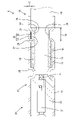
- FIG. 1 is a plan view of a shielded conductive path of Example 1.
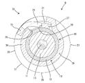
- FIG. 2 is a cross-sectional view taken along line XX of FIG. 1.
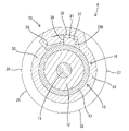
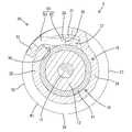
- FIG. 3 is a cross-sectional view taken along line YY of FIG.
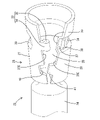
- FIG. 4 is a perspective view showing the form of the crimping portion before crimping.
- FIG. 5 is a partially exploded view of the crimping portion.
- FIG. 6 is a cross-sectional view corresponding to line YY in the shield conductive path of the second embodiment.
- FIG. 7 is a cross-sectional view corresponding to line YY of the shield conductive path of the third embodiment.
- FIG. 8 is a cross-sectional view corresponding to line YY in the shield conductive path of the fourth embodiment.
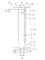
- FIG. 9 is a partial plan view of the shield conductive path of Example 5.
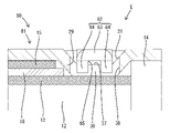
- FIG. 10 is a cross-sectional view taken along line ZZ of FIG. 9.
- FIG. 10 is a
- the shielded conductive path of the present disclosure includes: (1) A shielded wire having an insulating coating surrounding a core wire, a shield layer surrounding the insulating coating, and a sheath surrounding the shield layer, and an exposed portion of the shield layer extending forward of the sheath.
- the inner peripheral side locking portion is positioned radially inward of a region of the crimping portion surrounding the sleeve, and the outer peripheral side locking portion is formed with the inner peripheral side locking portion. is locked to the inner peripheral side locking portion in a state of being accommodated in the recess of the outer peripheral surface of the.
- the inner peripheral side locking portion is located radially inside the region of the crimping portion that surrounds the sleeve, and the outer peripheral side locking portion is located on the outer periphery of the inner peripheral side locking portion. Since it is accommodated in the recessed portion, it is possible to reduce the diameter as compared with the case where the crimping portion is not provided with the inner peripheral locking portion and the recessed portion.
- the crimping portion is formed with a retaining portion arranged at a position abutting against the sleeve from the rear or at a position closely facing the sleeve from the rear. According to this configuration, when a rearward tensile load is applied to the shielded wire, the rear end of the sleeve is engaged with the retaining portion, so that the shielded wire is displaced rearward relative to the shield terminal. can be prevented.
- the retaining portion extends continuously over at least half the circumference in the circumferential direction. According to this configuration, it is possible to reliably prevent the shielded wire from being displaced rearward relative to the shield terminal when a rearward tensile load acts on the shielded wire.
- the inner peripheral locking portion is formed in the retaining portion. According to this configuration, the shape of the crimping portion can be simplified as compared with the case where the inner peripheral side locking portion is formed in a portion different from the retaining portion.
- the depth dimension of the recess is equal to or greater than the plate thickness of the crimping portion. According to this configuration, since the entire outer peripheral side engaging portion is housed in the recess, it is possible to prevent the outer peripheral side engaging portion from partially protruding from the outer peripheral surface of the crimping portion.
- a locking hole is formed in one of the inner circumference side locking portion and the outer circumference side locking portion, and the other of the inner circumference side locking portion and the outer circumference side locking portion is formed with a locking hole. It is preferable that a locking protrusion that is locked in the locking hole is formed. According to this configuration, the crimping portion is prevented from being opened by the engagement of the locking protrusion with the hole edge of the locking hole.
- the longitudinal dimension of the locking hole is set larger than the longitudinal dimension of the locking protrusion. According to this configuration, even if there is a large dimensional tolerance of the crimping portion or an assembly error during crimping, the locking hole and the locking projection can be reliably locked.
- the circumferential opening dimension of the locking hole is set larger than the circumferential dimension of the locking projection. According to this configuration, even if there is a large dimensional tolerance of the crimping portion or an assembly error during crimping, the locking hole and the locking projection can be reliably locked.
- the locking hole is formed in the inner peripheral side locking portion and the locking protrusion is formed in the outer peripheral side locking portion. According to this configuration, since the locking portion between the hole edge of the locking hole and the locking projection is covered with the outer peripheral side locking portion, foreign matter does not enter the locking portion between the locking hole and the locking projection. can be prevented from interfering with
- the locking projection has a shape in which a portion of the inner circumference side locking section or the outer circumference side locking section is bent in a folded shape.
- This configuration corresponds to the first and second embodiments. According to this configuration, the locking strength of the locking protrusion is higher than that of the locking protrusion obtained by bending the leading edge of the inner peripheral side locking part or the outer peripheral side locking part at a right angle.
- the locking protrusion has a shape obtained by cutting and raising a part of the inner peripheral side locking part or the outer peripheral side locking part in the plate thickness direction.
- This configuration corresponds to the third and fourth embodiments. According to this configuration, the material cost can be reduced as compared with the case where the portion extending flush from the outer peripheral edge of the inner peripheral side locking portion or the outer peripheral side locking portion is bent.
- the locking protrusion has a shape obtained by bending the inner peripheral side locking part or the outer peripheral side locking part along a fold in the circumferential direction. .
- This configuration corresponds to the fifth embodiment. According to this configuration, since the locking projection has high rigidity against external force in the circumferential direction, it is possible to prevent the crimping portion from expanding and deforming due to the deformation of the locking projection.
- FIG. 1 A first embodiment embodying the present disclosure will be described with reference to FIGS. 1 to 5.
- FIG. The present invention is not limited to these exemplifications, but is indicated by the scope of the claims, and is intended to include all modifications within the scope and meaning equivalent to the scope of the claims.
- the front-rear direction the left side in FIGS. 1, 2 and 4 is defined as the front.
- the front-rear direction and the axial direction are used synonymously.
- the shield conductive path A of the first embodiment includes a shielded wire 10, a sleeve 18 fitted onto the shielded wire 10, and a sleeve 18 connected to the front end of the shielded wire 10. and a shield terminal 20 that is connected to the terminal.
- the shielded wire 10 has a configuration in which a core wire 11 is surrounded by an insulating coating 12 , a cylindrical shield layer 13 is overlaid on the outer periphery of the insulating coating 12 , and the outer periphery of the shield layer 13 is surrounded by a sheath 14 .
- the shield layer 13 is composed of a braided wire.
- the front end portion of the shielded wire 10 is arranged with its axial direction directed in the front-rear direction. As shown in FIG. 2 , the sheath 14 is removed from the front end of the shielded wire 10 , and the core wire 11 , insulation coating 12 and shield layer 13 are exposed forward of the sheath 14 . A portion of the insulating coating 12 is removed in front of the sheath 14 , and the core wire 11 is exposed in front of the insulating coating 12 .
- a sleeve 18 is fitted on a region of the outer peripheral surface of the shield layer 13 behind the front end of the insulating coating 12 .
- a sleeve 18 surrounds the shield layer 13 and the insulating coating 12 .
- a front end portion of the shield layer 13 is folded back to cover the outer circumference of the sleeve 18 .
- a region of the shield layer 13 surrounding the sleeve 18 is defined as a folded portion 15 .
- the rear end of the folded portion 15 is positioned slightly forward of the rear end of the sleeve 18 .
- the front end of the sleeve 18 is positioned slightly behind the front end of the insulating coating 12 .
- the rear end of the sleeve 18 is positioned forward of the front end of the sheath 14 .
- a region of the shielded wire 10 between the front end of the sheath 14 and the rear end of the sleeve 18 is defined as a functional portion 16 having a smaller diameter than the sheath 14 and the folded portion 15 .
- the shield terminal 20 includes an inner conductor 21 connected to the front end of the core wire 11, a dielectric 22 accommodating the inner conductor 21, and a dielectric 22 surrounding the outer periphery of the dielectric 22. and an attached outer conductor 23 .
- the outer conductor 23 has a cylindrical body portion 24 forming the front end portion of the outer conductor 23 and a cylindrical crimping portion 25 connecting to the rear end portion of the main body portion 24 and forming the rear end portion of the outer conductor 23 . configured with.
- the axial direction of the outer conductor 23 is coaxial with the axial direction of the shielded wire 10 and faces the front-rear direction.
- the inner conductor 21 and the dielectric 22 are accommodated in the body portion 24 .
- the crimping portion 25 is a portion for fixing the outer conductor 23 to the outer peripheral surface of the shielded wire 10 .
- the front end portion of the shielded wire 10 and the rear end portion of the shielded terminal 20 are connected in such a manner that they are restricted from being detached in the axial direction. and layer 13 are electrically connected.
- the crimping portion 25 includes a substrate portion 26 extending rearward from the rear end of the main body portion 24, and one direction (counterclockwise direction in FIG. 3) in the circumferential direction from the substrate portion 26. It has a first crimped portion 27 extending from the substrate portion 26 and a second crimped portion 28 extending in the opposite direction (clockwise direction in FIG. 3) from the first crimped portion 27 in the circumferential direction.
- the crimping portion 25 when the crimping portion 25 is not crimped to the shielded wire 10, the crimping portion 25 has a tapered shape that gradually increases in diameter from the front end to the rear end.
- a first extending edge 27E which is an edge on the leading end side in the extending direction of the first crimped portion 27, and a second extending edge 28E, which is an edge on the leading end side in the extending direction of the second crimped portion 28, They are separated in the circumferential direction.
- a retaining portion 29 extending in the circumferential direction is formed in a region of the crimping portion 25 that surrounds the functional portion 16 in the front-rear direction.
- the retaining portion 29 has a shape in which a portion of the crimping portion 25 is punched radially inward.
- the bottom plate portion 30 of the retainer portion 29 protrudes inward from the region of the crimping portion 25 surrounding the sheath 14 , the folded portion 15 and the sleeve 18 .
- a circumferential concave portion 31 is formed on the outer peripheral surface of the retaining portion 29 .
- the formation area of the retaining portion 29 in the circumferential direction is a range from a position closer to the substrate portion 26 than the first extending edge 27E to the second extending edge 28E. In a state where the crimping portion 25 is crimped, the retaining portion 29 extends continuously over a large portion in the circumferential direction, that is, over at least half the circumference.
- An outer peripheral locking portion 33 is formed integrally with the first crimped portion 27 . As shown in FIG. 4, the outer locking portion 33 protrudes in the circumferential direction from the first extending edge 27E toward the second extending edge 28E. As shown in FIG. 5 , the outer locking portion 33 is positioned on an extension line of the retaining portion 29 . That is, the outer peripheral locking portion 33 is arranged in a region of the first crimped portion 27 surrounding the functional portion 16 .
- the outer locking portion 33 has a base portion 34 protruding flush from the first caulked portion 27 and a locking protrusion 35 bent radially inward from the protruding end of the base portion 34 .
- the outer peripheral surface of the base portion 34 and the outer peripheral surface of the first crimped portion 27 are smoothly continuous, and the inner peripheral surface of the base portion 34 and the inner peripheral surface of the first crimped portion 27 are smoothly continuous.
- the locking protrusion 35 is arranged so as to overlap the inner peripheral surface of the base 34 and is located radially inward of the base 34 .
- the locking projection 35 has a projection shape projecting radially inward from the first crimped portion 27 .
- the width dimension of the locking projection 35 in the axial direction is the same as the width dimension of the base portion 34 in the axial direction.
- the locking protrusion 35 has a first locking surface 36 facing in the direction opposite to the projecting direction of the base 34 in the circumferential direction.
- a region of the retaining portion 29 close to the second extending edge 28E functions as an inner peripheral locking portion 37.
- the inner peripheral locking portion 37 has a square locking hole 38 penetrating through the retaining portion 29 from the outer peripheral side to the inner peripheral side.
- the inner surface parallel to the axial direction and closer to the second extending edge 28E in the circumferential direction functions as a second locking surface 39. .
- a first displacement restricting portion 40 is formed in a region forward of the outer peripheral locking portion 33 of the first extending edge 27E.
- the first displacement restricting portion 40 has a shape obtained by notching the first extending edge 27E in the circumferential direction.
- a second displacement restricting portion 41 is formed in a region of the second extending edge 28 ⁇ /b>E in front of the retaining portion 29 and the inner peripheral locking portion 37 .
- the second displacement restricting portion 41 has a shape that protrudes in the circumferential direction from the second extending edge 28E.
- the crimping portion 25 is crimped onto the shielded wire 10 by setting the crimping portion 25 and the front end portion of the shielded wire 10 on an applicator (not shown).
- the first crimped portion 27 and the second crimped portion 28 are crimped so as to be deformed to have a reduced diameter and wrap around the outer circumference of the shielded wire 10 .
- the outer peripheral surface is crimped, and the folded portion 15 is radially sandwiched between the sleeve 18 and the crimping portion 25 .
- the folded portion 15, the sleeve 18, and the crimping portion 25 are fixed in an integrated state so as to be electrically conductive.
- the outer locking portion 33 , the retaining portion 29 , and the inner locking portion 37 surround the functional portion 16 . Since the outer diameter dimension of the functional portion 16 is smaller than the outer diameter dimension of the sheath 14 and the outer diameter dimension of the folded portion 15 , the inner peripheral surface of the bottom plate portion 30 of the retainer portion 29 is positioned against the outer peripheral surface of the functional portion 16 . A contact state or a contact state with respect to the outer peripheral surface of the functional portion 16 is achieved.
- the outer locking portion 33 is accommodated in the recessed portion 31 on the outer peripheral surface of the retaining portion 29 and overlaps the outer peripheral surface of the inner locking portion 37 .
- the locking protrusion 35 of the outer locking portion 33 is accommodated in the locking hole 38 of the inner locking portion 37, and the first locking surface 36 and the second locking surface 39 contact and engage in the circumferential direction. It will be in a stopped state.
- the engagement between the first engagement surface 36 and the second engagement surface 39 prevents the crimping portion 25 from being deformed so as to open in the circumferential direction, and the crimping portion 25 is securely fixed to the outer circumference of the shielded wire 10 . be done.
- the front end of the retaining portion 29 is arranged at a position that abuts against the rear end of the sleeve 18 from the rear or at a position that closely faces the rear end of the sleeve 18 from the rear.
- the first crimped portion 27 and the first crimped portion 27 and The second crimped portion 28 is restricted from relative displacement in the axial direction. Since the outer locking portion 33 is accommodated in the recessed portion 31 of the retaining portion 29, the outer circumferential surface of the outer locking portion 33 extends radially from the outer circumferential surface of the region of the crimping portion 25 where the retaining portion 29 is not formed. It does not protrude outward.
- the shield conductive path A of Embodiment 1 includes a shield wire 10, a sleeve 18, and a shield terminal 20.
- a shielded wire 10 has an insulating coating 12 surrounding a core wire 11 , a shield layer 13 surrounding the insulating coating 12 , and a sheath 14 surrounding the shield layer 13 .
- the sleeve 18 surrounds the exposed portion of the shield layer 13 that extends forward of the sheath 14 and is crimped to the outer peripheral surface of the insulating coating 12 .
- the shield terminal 20 has an outer conductor 23 .
- An open-barrel crimp portion 25 is formed at the rear end portion of the outer conductor 23 . The crimping portion 25 is crimped to the sleeve 18 while surrounding the sleeve 18 and the region of the insulating coating 12 behind the sleeve 18 .
- An inner peripheral side locking portion 37 and an outer peripheral side locking portion 33 are formed in a region of the crimping portion 25 that covers the insulating coating 12 .
- the inner peripheral locking portion 37 is located radially inward of a region of the crimping portion 25 surrounding the sleeve 18 .
- the outer locking portion 33 is locked to the inner locking portion 37 while being accommodated in the recess 31 on the outer peripheral surface of the inner locking portion 37 . Therefore, the diameter of the shielded conductive path A according to the first embodiment can be reduced compared to the case where the crimping portion 25 is not provided with the inner locking portion 37 and the concave portion 31 .
- the depth dimension d (see FIG.
- the crimping portion 25 is formed with a retaining portion 29 arranged at a position abutting against the sleeve 18 from behind or at a position closely facing the sleeve 18 from behind.
- a rearward tensile load acts on the shielded wire 10
- the rear end of the sleeve 18 is engaged with the retaining portion 29 , so that the shielded wire 10 is displaced rearward relative to the shield terminal 20 . can be prevented.
- the retaining portion 29 extends continuously over at least half the circumference in the circumferential direction. According to this configuration, it is possible to reliably prevent the shielded wire 10 from being displaced rearward relative to the shield terminal 20 when a rearward tensile load acts on the shielded wire 10 .
- the inner peripheral locking portion 37 of the shield conductive path A of Embodiment 1 is formed in the retaining portion 29 .
- the shape of the crimping portion 25 of the shield conductive path A of the first embodiment can be simplified as compared with the case where the inner peripheral locking portion 37 is formed at a portion different from the retaining portion 29 .
- a locking hole 38 is formed in the inner peripheral side locking portion 37 , and a locking protrusion 35 that is locked in the locking hole 38 is formed in the outer peripheral side locking portion 33 .
- the engagement of the locking projection 35 with the edge of the locking hole 38 prevents the crimping portion 25 from opening.
- the locking portion between the hole edge of the locking hole 38 and the locking projection 35 is covered with the outer locking portion 33 , so that the locking hole 38 and the locking projection 35 are separated from each other. Foreign matter can be prevented from interfering with the locking portion.
- the longitudinal opening dimension Wa of the locking hole 38 is set larger than the longitudinal dimension Wb of the locking protrusion 35 .
- a circumferential opening dimension Da of the locking hole 38 is set larger than a circumferential dimension Db of the locking projection 35 . According to this configuration, even if the dimensional tolerance of the crimping portion 25 or the assembly error during crimping is large, the locking hole 38 and the locking protrusion 35 can be securely locked.
- the locking projection 35 of the first embodiment has a shape in which a portion of the outer locking portion 33 is bent in a folded shape.
- the locking strength of the locking projection 35 of the shield conductive path A of the first embodiment is higher than that of the locking projection formed by bending the tip edge of the outer locking portion at right angles.
- Example 2 A second embodiment embodying the present disclosure will be described with reference to FIG.
- the crimped portion 51 of the outer conductor 50 has a structure different from that of the first embodiment. Since other configurations are the same as those of the first embodiment, the same configurations are denoted by the same reference numerals, and descriptions of the structures, actions and effects are omitted.
- the crimping portion 51 of the second embodiment includes the substrate portion 26, the first crimped portion 27 extending from the substrate portion 26 in one direction in the circumferential direction, and the first crimped portion 27 opposite to the first crimped portion 27 in the circumferential direction from the substrate portion 26. and a second caulked portion 28 extending in the direction.
- the crimping portion 51 When the crimping portion 51 is not crimped to the shielded wire 10, the crimping portion 51 has a tapered shape that gradually increases in diameter from the front end to the rear end.
- a retainer portion 29 extending in the circumferential direction is formed as in the first embodiment.
- An outer peripheral locking portion 52 is formed integrally with the first crimped portion 27 .
- the outer locking portion 52 protrudes in the circumferential direction from the first extended edge (not shown) of the first crimped portion 27 toward the second extended end (not shown) of the second crimped portion 28 . .
- the outer locking portion 52 is positioned on an extension line of the retaining portion 29 . That is, the outer locking portion 52 is arranged in a region of the first crimped portion 27 surrounding the functional portion 16 .
- the outer circumferential surface of the outer locking portion 52 and the outer circumferential surface of the first crimped portion 27 are smoothly continuous, and the inner circumferential surface of the outer circumferential locking portion 52 and the inner circumferential surface of the first crimped portion 27 are smoothly continuous.
- the outer locking portion 52 has a square locking hole 53 penetrating the outer locking portion 52 from the outer circumference to the inner circumference.
- the inner surface parallel to the axial direction and farther from the first extending edge 27E (not shown) functions as a first locking surface 54. do.
- a region of the retaining portion 29 that is close to the second extending edge 28E (not shown) functions as an inner peripheral locking portion 55 .
- the inner peripheral locking portion 55 has a locking protrusion 57 formed by bending the second extending edge 28E of the bottom plate portion 30 of the retaining portion 29 radially outward.
- the locking protrusion 57 is arranged so as to overlap the outer peripheral surface of the bottom plate portion 30 and is located radially inward of the bottom plate portion 30 .
- the locking protrusion 57 has a projection shape projecting radially outward from the bottom plate portion 30 and is accommodated in the recess 31 of the outer peripheral surface of the inner peripheral side locking portion 55 .
- the locking protrusion 57 has a second locking surface 58 facing in the circumferential direction.
- the outer locking portion 52 , the retaining portion 29 and the inner locking portion 55 surround the functional portion 16 . Since the outer diameter of the functional portion 16 is smaller than the outer diameter of the sheath (not shown) and the outer diameter of the folded portion (not shown), the inner peripheral surface of the retaining portion 29 is aligned with the outer peripheral surface of the functional portion 16. , or in contact with the outer peripheral surface of the functional portion 16 .
- the outer locking portion 52 is accommodated in the recess 31 on the outer peripheral surface of the retaining portion 29 and overlaps the outer peripheral surface of the inner locking portion 55 .
- the locking protrusion 57 of the inner locking portion 55 is accommodated in the locking hole 53 of the outer locking portion 52, and the first locking surface 54 and the second locking surface 58 contact and engage in the circumferential direction. It will be in a stopped state.
- the engagement between the first engagement surface 54 and the second engagement surface 58 prevents the crimping portion 51 from being deformed so as to open in the circumferential direction, and the crimping portion 51 is securely fixed to the outer circumference of the shielded wire 10 . be done.
- Example 3 A third embodiment embodying the present disclosure will be described with reference to FIG.
- the outer engaging portion 62 forming the crimping portion 61 of the outer conductor 60 is configured differently from that of the first embodiment. Since other configurations are the same as those of the second embodiment, the same configurations are denoted by the same reference numerals, and descriptions of the structures, functions and effects are omitted.
- the outer-peripheral-side engaging portion 62 of Embodiment 3 has an engaging projection 63 formed by cutting and raising a portion of the outer-peripheral-side engaging portion 62 of the first crimped portion 27 radially inward.
- the locking protrusion 63 has a bent portion 64 and an abutment portion 65 .
- the bent portion 64 protrudes in the circumferential direction from the distal end portion side of the outer peripheral locking portion 62 toward the proximal end portion side.
- the bent portion 64 has a shape bent so as to protrude radially inward from the distal end portion of the outer locking portion 62 .
- the abutting portion 65 extends in the circumferential direction from the projecting end of the bent portion 64 .
- the projection dimension of the abutting portion 65 from the outer peripheral side locking portion 62 to the radially inner side is the same as the plate thickness of the inner peripheral side locking portion 37 .
- the extending end surface of the abutting portion 65 functions as a first locking surface 66 perpendicular to the circumferential direction.
- the outer locking portion 62 is accommodated in the recessed portion 31 of the retaining portion 29 and overlaps the outer circumference of the inner locking portion 37 .
- a portion of the locking protrusion 63 enters the locking hole 38 of the inner circumferential side locking portion 37 . That is, part of the bent portion 64 and the entire abutting portion 65 are accommodated in the locking hole 38 .
- the first locking surface 66 contacts the second locking surface 39 of the locking hole 38 in the circumferential direction, and the first locking surface 66 and the second locking surface 39 are locked. Due to this locking action, the crimping portion 61 is prevented from being expanded and deformed, and the crimping state of the crimping portion 61 to the shielded wire 10 is maintained.
- the locking protrusion 63 has a shape obtained by cutting and raising a portion of the outer circumferential locking portion 62 in the plate thickness direction of the outer circumferential locking portion 62 .
- the material cost of the shield conductive path C of the third embodiment can be reduced as compared with the case in which the portion extending flush from the outer peripheral edge of the outer engaging portion 62 is bent.
- Example 4 A fourth embodiment embodying the present disclosure will be described with reference to FIG.
- the outer engaging portion 72 constituting the crimping portion 71 of the outer conductor 70 is configured differently from that of the first embodiment. Since other configurations are the same as those of the first embodiment, the same configurations are denoted by the same reference numerals, and descriptions of the structures, actions and effects are omitted.
- the outer-periphery-side locking portion 72 of the fourth embodiment has a locking protrusion 73 formed by cutting and raising a portion of the first crimped portion 27 radially inward.
- the locking protrusion 73 protrudes in the circumferential direction from the distal end side of the outer circumferential locking part 72 toward the proximal end side.
- the radially inward projection dimension of the locking protrusion 73 from the outer circumferential locking portion 72 is the same as the plate thickness of the inner circumferential locking portion 37 .
- the outer locking portion 72 is accommodated in the recessed portion 31 of the retaining portion 29 and overlaps the outer circumference of the inner locking portion 37 .
- a portion of the locking protrusion 73 is accommodated in the locking hole 38 of the inner peripheral side locking portion 37 , and the projecting edge of the locking protrusion 73 faces the second locking surface 39 of the locking hole 38 . Circumferentially locked in line contact. This locking action prevents the crimping portion 71 from expanding and deforming, and the crimping state of the crimping portion 71 to the shielded wire 10 is maintained.
- the locking protrusion 73 has a shape obtained by cutting and raising a portion of the outer circumferential locking portion 72 in the plate thickness direction of the outer circumferential locking portion 72 . According to this configuration, the material cost of the shield conductive path D of the fourth embodiment can be reduced as compared with the case in which the portion extending flush from the outer peripheral edge of the outer engaging portion 72 is bent. .
- FIG. 5 A fifth embodiment embodying the present disclosure will be described with reference to FIGS. 9 to 10.
- the outer peripheral locking portion 82 of the fifth embodiment has a base portion 83 and a pair of front and rear locking protrusions 84 .
- the base portion 83 is flush with the first caulked portion 27 and protrudes in the circumferential direction from the first extending edge 27E.
- the pair of locking protrusions 84 are obtained by bending the front edge and the rear edge of the base portion 83 at right angles to the base portion 83 .
- a boundary line between the base portion 83 and the locking projection 84, that is, a crease 85 of the locking projection 84 extends along the circumferential direction.
- the locking protrusion 84 has a form that protrudes radially inward from the inner peripheral surfaces of the base portion 83 and the first crimped portion 27 .
- the projection dimension in the radial direction of the locking projection 84 is the same dimension as the plate thickness of the second crimped portion 28 and the inner circumference side locking portion 37 .
- the locking protrusion 84 is arranged at a position spaced apart in the circumferential direction from the first extending end edge 27E, that is, in a region of the base 83 on the protruding end side.
- a surface of the locking protrusion 84 facing the first extending edge 27E functions as a first locking surface 86 perpendicular to the circumferential direction.
- the outer locking part 82 is accommodated in the recessed part 31 of the retaining part 29 and overlapped with the outer circumference of the inner locking part 37 .
- a pair of front and rear locking projections 84 are accommodated in the locking hole 38 of the inner peripheral side locking portion 37 , and the first locking surface 86 of the locking projection 84 is aligned with the second locking surface 39 of the locking hole 38 . Circumferentially locked against. Due to this locking action, the crimping portion 81 is prevented from being expanded and deformed, and the crimping state of the crimping portion 81 to the shielded wire 10 is maintained.
- the locking projection 84 has a shape obtained by bending the outer circumferential side locking portion 82 along the circumferential crease 85, so it has high rigidity against external forces in the circumferential direction. Therefore, the shield conductive path E of the fifth embodiment can prevent the crimping portion 81 from being expanded and deformed due to the deformation of the locking protrusion 84 .
- one retaining portion extends continuously in the circumferential direction, but a plurality of retaining portions are arranged at intervals in the circumferential direction, and are closest to the outer locking portion in the circumferential direction.
- An inner peripheral side retaining portion may be formed in the retaining portion.
- the retaining portion extends over most of the circumferential direction (at least a half circumference area), but the retaining portion has a minimum area necessary for locking with the outer locking portion.
- the inner peripheral side engaging portion is formed in the retaining portion, but the inner peripheral side engaging portion may be formed in a portion other than the retaining portion.
- the front end portion of the shield layer is folded back to form a folded portion surrounding the outer peripheral surface of the sleeve, but the front end portion of the shield layer may not be folded back.
- the crimping portion surrounds the outer peripheral surface of the sheath, but the crimping portion may not surround the outer peripheral surface of the sheath.
- the shield layer is formed of a braided wire, but the shield layer may be a metal foil.
- the locking protrusion may be formed in the inner peripheral side locking portion, and the locking hole may be formed in the outer peripheral side locking portion.
Landscapes
- Details Of Connecting Devices For Male And Female Coupling (AREA)
- Connections Effected By Soldering, Adhesion, Or Permanent Deformation (AREA)
Priority Applications (2)
| Application Number | Priority Date | Filing Date | Title |
|---|---|---|---|
| CN202280044399.6A CN117546375A (zh) | 2021-07-07 | 2022-06-17 | 屏蔽导电路径 |
| US18/576,096 US20240313482A1 (en) | 2021-07-07 | 2022-06-17 | Shielded electrically conductive path |
Applications Claiming Priority (2)
| Application Number | Priority Date | Filing Date | Title |
|---|---|---|---|
| JP2021112601A JP7524849B2 (ja) | 2021-07-07 | 2021-07-07 | シールド導電路 |
| JP2021-112601 | 2021-07-07 |
Publications (1)
| Publication Number | Publication Date |
|---|---|
| WO2023282031A1 true WO2023282031A1 (ja) | 2023-01-12 |
Family
ID=84800192
Family Applications (1)
| Application Number | Title | Priority Date | Filing Date |
|---|---|---|---|
| PCT/JP2022/024362 Ceased WO2023282031A1 (ja) | 2021-07-07 | 2022-06-17 | シールド導電路 |
Country Status (4)
| Country | Link |
|---|---|
| US (1) | US20240313482A1 (enExample) |
| JP (1) | JP7524849B2 (enExample) |
| CN (1) | CN117546375A (enExample) |
| WO (1) | WO2023282031A1 (enExample) |
Families Citing this family (1)
| Publication number | Priority date | Publication date | Assignee | Title |
|---|---|---|---|---|
| JP7766984B2 (ja) * | 2022-02-14 | 2025-11-11 | 矢崎総業株式会社 | シールド電線とシールド部材の接続構造、シールド部材 |
Citations (3)
| Publication number | Priority date | Publication date | Assignee | Title |
|---|---|---|---|---|
| JP2006244815A (ja) * | 2005-03-02 | 2006-09-14 | Sumitomo Wiring Syst Ltd | バレル部の構造 |
| JP2013206620A (ja) * | 2012-03-27 | 2013-10-07 | Sumitomo Wiring Syst Ltd | 同軸ケーブル用端子 |
| JP2019021632A (ja) * | 2017-07-15 | 2019-02-07 | ローゼンベルガー ホーフフレクベンツテクニーク ゲーエムベーハー ウント ツェーオー カーゲー | コネクタ装置 |
-
2021
- 2021-07-07 JP JP2021112601A patent/JP7524849B2/ja active Active
-
2022
- 2022-06-17 CN CN202280044399.6A patent/CN117546375A/zh active Pending
- 2022-06-17 US US18/576,096 patent/US20240313482A1/en active Pending
- 2022-06-17 WO PCT/JP2022/024362 patent/WO2023282031A1/ja not_active Ceased
Patent Citations (3)
| Publication number | Priority date | Publication date | Assignee | Title |
|---|---|---|---|---|
| JP2006244815A (ja) * | 2005-03-02 | 2006-09-14 | Sumitomo Wiring Syst Ltd | バレル部の構造 |
| JP2013206620A (ja) * | 2012-03-27 | 2013-10-07 | Sumitomo Wiring Syst Ltd | 同軸ケーブル用端子 |
| JP2019021632A (ja) * | 2017-07-15 | 2019-02-07 | ローゼンベルガー ホーフフレクベンツテクニーク ゲーエムベーハー ウント ツェーオー カーゲー | コネクタ装置 |
Also Published As
| Publication number | Publication date |
|---|---|
| JP7524849B2 (ja) | 2024-07-30 |
| CN117546375A (zh) | 2024-02-09 |
| JP2024133300A (ja) | 2024-10-01 |
| JP2023009380A (ja) | 2023-01-20 |
| US20240313482A1 (en) | 2024-09-19 |
Similar Documents
| Publication | Publication Date | Title |
|---|---|---|
| JP3365550B2 (ja) | シールド端子 | |
| JP7240607B2 (ja) | ケーブル付きコネクタ | |
| JP6863164B2 (ja) | 電線の圧着構造及びシールド導電路 | |
| US12388196B2 (en) | Shielded electrically conductive path | |
| JPH08250218A (ja) | シールド線のシースずれ防止構造 | |
| JP4767760B2 (ja) | シールド電線用アース端子 | |
| WO2023282031A1 (ja) | シールド導電路 | |
| US12413013B2 (en) | Shielded electrically conductive cable connector | |
| JP7792070B2 (ja) | シールド導電路 | |
| JP7679796B2 (ja) | 電線と外導体との圧着構造 | |
| JP7687179B2 (ja) | ワイヤハーネス | |
| WO2013030955A1 (ja) | シールド電線のアース接続構造 | |
| JP4392381B2 (ja) | シールドコネクタ | |
| JP7624154B2 (ja) | シールド導電路 | |
| JP7737613B2 (ja) | 電線と外導体との圧着構造 | |
| JP2021180089A (ja) | コネクタ装置 | |
| JP2015079651A (ja) | シールド電線の端末接続構造 | |
| WO2023149116A1 (ja) | コネクタ |
Legal Events
| Date | Code | Title | Description |
|---|---|---|---|
| 121 | Ep: the epo has been informed by wipo that ep was designated in this application |
Ref document number: 22837449 Country of ref document: EP Kind code of ref document: A1 |
|
| WWE | Wipo information: entry into national phase |
Ref document number: 202280044399.6 Country of ref document: CN |
|
| NENP | Non-entry into the national phase |
Ref country code: DE |
|
| 122 | Ep: pct application non-entry in european phase |
Ref document number: 22837449 Country of ref document: EP Kind code of ref document: A1 |