WO2023281821A1 - 内接歯車ポンプ及び内接歯車モータ - Google Patents
内接歯車ポンプ及び内接歯車モータ Download PDFInfo
- Publication number
- WO2023281821A1 WO2023281821A1 PCT/JP2022/010369 JP2022010369W WO2023281821A1 WO 2023281821 A1 WO2023281821 A1 WO 2023281821A1 JP 2022010369 W JP2022010369 W JP 2022010369W WO 2023281821 A1 WO2023281821 A1 WO 2023281821A1
- Authority
- WO
- WIPO (PCT)
- Prior art keywords
- internal gear
- communicating
- grooves
- communication
- pressure region
- Prior art date
- Legal status (The legal status is an assumption and is not a legal conclusion. Google has not performed a legal analysis and makes no representation as to the accuracy of the status listed.)
- Ceased
Links
Images






Classifications
-
- F—MECHANICAL ENGINEERING; LIGHTING; HEATING; WEAPONS; BLASTING
- F04—POSITIVE - DISPLACEMENT MACHINES FOR LIQUIDS; PUMPS FOR LIQUIDS OR ELASTIC FLUIDS
- F04C—ROTARY-PISTON, OR OSCILLATING-PISTON, POSITIVE-DISPLACEMENT MACHINES FOR LIQUIDS; ROTARY-PISTON, OR OSCILLATING-PISTON, POSITIVE-DISPLACEMENT PUMPS
- F04C2/00—Rotary-piston machines or pumps
- F04C2/08—Rotary-piston machines or pumps of intermeshing-engagement type, i.e. with engagement of co-operating members similar to that of toothed gearing
- F04C2/10—Rotary-piston machines or pumps of intermeshing-engagement type, i.e. with engagement of co-operating members similar to that of toothed gearing of internal-axis type with the outer member having more teeth or tooth-equivalents, e.g. rollers, than the inner member
- F04C2/102—Rotary-piston machines or pumps of intermeshing-engagement type, i.e. with engagement of co-operating members similar to that of toothed gearing of internal-axis type with the outer member having more teeth or tooth-equivalents, e.g. rollers, than the inner member the two members rotating simultaneously around their respective axes
-
- F—MECHANICAL ENGINEERING; LIGHTING; HEATING; WEAPONS; BLASTING
- F04—POSITIVE - DISPLACEMENT MACHINES FOR LIQUIDS; PUMPS FOR LIQUIDS OR ELASTIC FLUIDS
- F04C—ROTARY-PISTON, OR OSCILLATING-PISTON, POSITIVE-DISPLACEMENT MACHINES FOR LIQUIDS; ROTARY-PISTON, OR OSCILLATING-PISTON, POSITIVE-DISPLACEMENT PUMPS
- F04C2/00—Rotary-piston machines or pumps
- F04C2/08—Rotary-piston machines or pumps of intermeshing-engagement type, i.e. with engagement of co-operating members similar to that of toothed gearing
- F04C2/082—Details specially related to intermeshing engagement type machines or pumps
- F04C2/086—Carter
-
- F—MECHANICAL ENGINEERING; LIGHTING; HEATING; WEAPONS; BLASTING
- F01—MACHINES OR ENGINES IN GENERAL; ENGINE PLANTS IN GENERAL; STEAM ENGINES
- F01C—ROTARY-PISTON OR OSCILLATING-PISTON MACHINES OR ENGINES
- F01C21/00—Component parts, details or accessories not provided for in groups F01C1/00 - F01C20/00
- F01C21/10—Outer members for co-operation with rotary pistons; Casings
- F01C21/104—Stators; Members defining the outer boundaries of the working chamber
- F01C21/108—Stators; Members defining the outer boundaries of the working chamber with an axial surface, e.g. side plates
-
- F—MECHANICAL ENGINEERING; LIGHTING; HEATING; WEAPONS; BLASTING
- F04—POSITIVE - DISPLACEMENT MACHINES FOR LIQUIDS; PUMPS FOR LIQUIDS OR ELASTIC FLUIDS
- F04C—ROTARY-PISTON, OR OSCILLATING-PISTON, POSITIVE-DISPLACEMENT MACHINES FOR LIQUIDS; ROTARY-PISTON, OR OSCILLATING-PISTON, POSITIVE-DISPLACEMENT PUMPS
- F04C15/00—Component parts, details or accessories of machines, pumps or pumping installations, not provided for in groups F04C2/00 - F04C14/00
- F04C15/0003—Sealing arrangements in rotary-piston machines or pumps
- F04C15/0023—Axial sealings for working fluid
- F04C15/0026—Elements specially adapted for sealing of the lateral faces of intermeshing-engagement type machines or pumps, e.g. gear machines or pumps
-
- F—MECHANICAL ENGINEERING; LIGHTING; HEATING; WEAPONS; BLASTING
- F04—POSITIVE - DISPLACEMENT MACHINES FOR LIQUIDS; PUMPS FOR LIQUIDS OR ELASTIC FLUIDS
- F04C—ROTARY-PISTON, OR OSCILLATING-PISTON, POSITIVE-DISPLACEMENT MACHINES FOR LIQUIDS; ROTARY-PISTON, OR OSCILLATING-PISTON, POSITIVE-DISPLACEMENT PUMPS
- F04C15/00—Component parts, details or accessories of machines, pumps or pumping installations, not provided for in groups F04C2/00 - F04C14/00
- F04C15/0042—Systems for the equilibration of forces acting on the machines or pump
- F04C15/0049—Equalization of pressure pulses
-
- F—MECHANICAL ENGINEERING; LIGHTING; HEATING; WEAPONS; BLASTING
- F04—POSITIVE - DISPLACEMENT MACHINES FOR LIQUIDS; PUMPS FOR LIQUIDS OR ELASTIC FLUIDS
- F04C—ROTARY-PISTON, OR OSCILLATING-PISTON, POSITIVE-DISPLACEMENT MACHINES FOR LIQUIDS; ROTARY-PISTON, OR OSCILLATING-PISTON, POSITIVE-DISPLACEMENT PUMPS
- F04C2/00—Rotary-piston machines or pumps
- F04C2/08—Rotary-piston machines or pumps of intermeshing-engagement type, i.e. with engagement of co-operating members similar to that of toothed gearing
- F04C2/082—Details specially related to intermeshing engagement type machines or pumps
- F04C2/084—Toothed wheels
-
- F—MECHANICAL ENGINEERING; LIGHTING; HEATING; WEAPONS; BLASTING
- F04—POSITIVE - DISPLACEMENT MACHINES FOR LIQUIDS; PUMPS FOR LIQUIDS OR ELASTIC FLUIDS
- F04C—ROTARY-PISTON, OR OSCILLATING-PISTON, POSITIVE-DISPLACEMENT MACHINES FOR LIQUIDS; ROTARY-PISTON, OR OSCILLATING-PISTON, POSITIVE-DISPLACEMENT PUMPS
- F04C2/00—Rotary-piston machines or pumps
- F04C2/08—Rotary-piston machines or pumps of intermeshing-engagement type, i.e. with engagement of co-operating members similar to that of toothed gearing
- F04C2/10—Rotary-piston machines or pumps of intermeshing-engagement type, i.e. with engagement of co-operating members similar to that of toothed gearing of internal-axis type with the outer member having more teeth or tooth-equivalents, e.g. rollers, than the inner member
- F04C2/101—Rotary-piston machines or pumps of intermeshing-engagement type, i.e. with engagement of co-operating members similar to that of toothed gearing of internal-axis type with the outer member having more teeth or tooth-equivalents, e.g. rollers, than the inner member with a crescent-shaped filler element, located between the inner and outer intermeshing members
-
- F—MECHANICAL ENGINEERING; LIGHTING; HEATING; WEAPONS; BLASTING
- F04—POSITIVE - DISPLACEMENT MACHINES FOR LIQUIDS; PUMPS FOR LIQUIDS OR ELASTIC FLUIDS
- F04C—ROTARY-PISTON, OR OSCILLATING-PISTON, POSITIVE-DISPLACEMENT MACHINES FOR LIQUIDS; ROTARY-PISTON, OR OSCILLATING-PISTON, POSITIVE-DISPLACEMENT PUMPS
- F04C14/00—Control of, monitoring of, or safety arrangements for, machines, pumps or pumping installations
- F04C14/08—Control of, monitoring of, or safety arrangements for, machines, pumps or pumping installations characterised by varying the rotational speed
Definitions
- the present invention relates to an internal gear pump and an internal gear motor.
- Patent Document 1 discloses that one pressure introduction groove is provided in a cover, which is a sealing member that abuts on the side surfaces of both gears, and is formed between the crescent and the tooth grooves of the gears. The enclosed space and the high pressure area are communicated with each other.
- the inventors of the present invention have found that in a conventional internal gear pump provided with a single pressure introduction groove having a monotonic shape, when the gear rotates at a high speed, the gear rotates at a low speed. It was found that the timing of the pressure rise in the tooth space due to rotation is delayed compared to the conventional method.
- the inventor of the present invention has conducted extensive research and found that, in conventional internal gear pumps, the difference in the timing of the pressure rise in the tooth spaces between high and low rotations is large. Therefore, when the rotation speed of the pump is changed from low to high, the ratio of the high pressure region in the liquid feeding space changes greatly. As a result, the pressure balance is lost, and the performance and durability of the pump may be lowered. The same can be said for an internal gear motor having a configuration similar to this phenomenon.
- the main object of the present invention is to reduce the difference in the timing of pressure changes in the tooth spaces between low rotation and high rotation.
- a first aspect of the present invention includes an internal gear rotatably fitted in a body, an external gear that internally contacts and meshes with the internal gear, and a transmission gear formed between the internal gear and the external gear.
- a filler piece that partitions a liquid space into a high pressure region and a low pressure region;
- a communication groove is formed for communicating between the surrounding space surrounded by the tooth groove of one of the gears and the high pressure region, and the communication groove communicates with the surrounding space as the rotation phase of the two gears advances.
- the present invention relates to an internal gear pump which is formed such that the cross-sectional area to be pumped continuously increases and the rate of increase increases at an accelerated rate.
- an internal gear is rotatably fitted in a body, an external gear is in contact with and meshes with the internal gear, and the gear is formed between the internal gear and the external gear.
- a filler piece that divides a liquid feeding space into a high-pressure region and a low-pressure region;
- a communication groove is formed for communicating between the surrounding space surrounded by the tooth grooves of at least one of the gears and the low-pressure region, and the communication groove extends into the surrounding space as the rotation phase of the two gears advances.
- the present invention relates to an internal gear motor in which a communicating cross-sectional area continuously increases and the rate of increase increases at an accelerated rate.
- the cross-sectional area of the communicating groove communicating with the surrounding space continuously increases as the rotation phase of both gears advances, and the rate of increase increases at an accelerating rate.
- the amount of hydraulic fluid (such as oil) introduced from the communication grooves into the tooth spaces of the gear can be increased at an accelerated rate with rotation. Therefore, compared to the conventional gear in which only one monotonic communication groove is formed, the timing of the pressure change in the tooth spaces during low rotation of both gears is not greatly advanced, and the tooth spaces during high rotation are improved. Only the timing of pressure changes within can be greatly advanced.
- the internal gear pump and the internal gear motor it is possible to reduce the difference in the timing of the pressure change in the tooth spaces between low rotation and high rotation, thereby improving the performance and durability of the pump.
- FIG. 1 is a longitudinal sectional view showing the configuration of an internal gear pump according to a first embodiment of the invention
- FIG. FIG. 2 is a cross-sectional view showing the configuration of the internal gear pump of the same embodiment
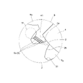
- the figure which expands and shows the B section of FIG. The figure which shows the relationship between the rotation phase of the internal gear pump of the same embodiment, and the total cross-sectional area of a communication groove.
- FIG. 4 is an enlarged view showing the configuration around the communicating grooves when there are a plurality of communicating grooves and the communication timings of the communicating grooves are the same;
- FIG. 4 is an enlarged view showing the configuration around the communicating grooves when there are a plurality of communicating grooves and the communication timings of the communicating grooves are the same;
- FIG. 5 is a diagram showing the relationship between the rotational phase of the internal gear pump and the total cross-sectional area of the communication grooves when there are a plurality of communication grooves and the communication timings of the communication grooves match.
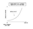
- FIG. 5 is a diagram showing the relationship between the rotational phase of the internal gear pump and the pressure in the tooth spaces when there are a plurality of communication grooves and the communication timings of the communication grooves match.
- FIG. 5 is a cross-sectional view showing the configuration of an internal gear pump according to a second embodiment of the present invention; The figure which expands and shows the C section of FIG. The figure which expands and shows the D section of FIG. The figure which shows the structure of the inner communicating groove
- the internal gear pump 100 of the present embodiment is used as a hydraulic source for, for example, industrial vehicles, construction machinery, agricultural machinery, and the like. By rotating the gear 3, fluid (oil such as mineral oil, also called hydraulic fluid) is sucked and discharged.
- this internal gear pump 100 includes a body 1, an internal gear 2, an external gear 3, a filler piece 4, and a sealing member 5, as shown in FIGS.
- the body 1 has a substantially cylindrical hollow body shape. As shown in FIG. 1 , an opening on one axial end side of the body 1 is closed by a front cover 7 , and an opening on the other axial end side is closed by a rear cover 8 . As shown in FIG. 2, the side wall 11 of the body 1 is formed with through holes communicating with an inlet P i for sucking oil and an outlet P o for discharging oil.
- the internal gear 2 is a ring-shaped gear having a plurality of radially inward teeth 22, and is a so-called internal gear.
- the internal gear 2 is rotatably fitted and accommodated in the body 1 so that its rotation axis is parallel to the axial direction of the body 1 .
- the external gear 3 has a plurality of radially outward teeth 32, and is a so-called pinion gear.
- the external gear 3 has a smaller reference circle diameter than the internal gear 2 and has fewer teeth than the internal gear 2 .
- the external gear 3 is arranged so that its rotation axis is parallel to the rotation axis of the internal gear 2 so as to be in contact with and mesh with the internal gear 2 .
- a liquid feeding space is formed between the external gear 3 and the internal gear 2 .
- a drive shaft 9 is connected to the rotation shaft of the external gear 3 for rotationally driving it.
- the filler piece 4 is provided between the internal gear 2 and the external gear 3 in the body 1 and divides the liquid feeding space into a high pressure region RH and a low pressure region RL .
- the filler piece 4 has a crescent shape integrally protruding from the front cover 7, and has an outer peripheral surface 41 in contact with the tip of the internal gear 2 and an inner peripheral surface 41 in contact with the tip of the external gear 3. a peripheral surface 42;
- the outer peripheral surface 41 has the same circular diameter as the addendum circle diameter of the internal gear 2 , and is in contact with a plurality of addendums of the internal gear 2 at the same time to seal oil accumulated in the tooth spaces 21 thereof.
- the inner peripheral surface 42 has the same diameter as the addendum circle diameter of the external gear 3 , and is in contact with a plurality of addendums of the external gear 3 simultaneously to seal oil accumulated in the tooth spaces 31 .
- a plurality of surrounding spaces T (outer surrounding spaces T o ) are formed between the filler piece 4 and the internal gear 2 .
- there are a plurality of surrounding spaces T (also referred to as inner surrounding spaces Ti) surrounded by the inner peripheral surface 42 of the filler piece 4 and the tooth spaces 31 of the external gear 3. formed.
- the high pressure region RH and the low pressure region RL communicate with the suction port P i and the discharge port P o through ports (not shown), respectively.
- the sealing member 5 of the present embodiment is inserted between the body 1 and the gears 2 and 3 so as to cover both end surfaces of the internal gear 2 and the external gear 3 to seal the liquid feeding space.
- the sealing member 5 also referred to as a side plate
- the sealing member 5 is a plate-like member having a certain thickness, and is fitted to the inner circumference of the body 1 so as to be slidable in the axial direction.
- the sealing member 5 is provided with a communication port 51 that communicates the high pressure region RH with the space between the sealing member 5 and the front cover 7 (or the rear cover 8).
- the communication port 51 is formed by a through hole penetrating the sealing member 5 in the plate thickness direction, and is open on both side surfaces of the sealing member 5 .
- a plurality of (specifically, two) communication ports 51 are provided in the sealing member 5, and each communication port 51 is located in the high pressure region RH of the rotating internal gear 2 when viewed from the rotation axis direction.
- the tooth 22 and the tooth 32 of the external gear 3 are provided at a position passing thereover.
- a communication groove 6 for communicating the high pressure region RH and the surrounding space T is formed in the sealing member 5 .
- This communication groove 6 is for gradually increasing the pressure in the surrounding space T by introducing oil from the high pressure region RH into the surrounding space T having a relatively low pressure.
- the drive shaft 9 rotates the external gear 3 and the internal gear 2 to discharge the oil sucked from the suction port Pi from the discharge port Po .
- oil which is the hydraulic fluid
- the suction port P i into the low pressure region RL
- the surrounding space T is carried to the high pressure region RH , and discharged from the discharge port Po .
- the cross-sectional area of the communication groove 6 communicating with the surrounding space T continuously increases as the rotation phase of both gears 2 and 3 advances, and the rate of increase increases. is formed to rise at an accelerated rate.
- a plurality of communication grooves 6 are formed to communicate the surrounding space T and the high pressure region RH , and each communication groove 6 is connected to the internal gear 2 and the external gear 3.
- the high pressure region RH and the surrounding space T are formed to communicate with each other at different timings as they rotate.
- the sealing member 5 includes a plurality of inner communication grooves 6 i for communicating the high pressure region RH and the inner surrounding space T i , and the high pressure region RH
- a plurality of outer communication grooves 6 o are formed as the communication grooves 6 for communicating with the outer surrounding space T 0 .
- the inner communication grooves 6i have different timings for communicating the high pressure region RH and the inner surrounding space Ti with the rotation of the gears 2 and 3.
- the timings for communicating the high pressure region RH and the outer surrounding space T0 with the second and third rotations are different from each other.
- the plurality of inner communicating grooves 6i and the plurality of outer communicating grooves 6o are formed in the sealing member 5 in the same number (three in this case). These communication grooves 6 i and 6 o are arranged in accordance with the rotation of both gears 2 and 3 so that the timing at which the inner enclosing space T i contacts each inner communication groove 6 i and the timing at which the outer enclosing space T 0 reaches each outer communication groove. 6o is formed so as to coincide with the timing.
- each communication groove 6 has a needle shape formed along the side surface of the sealing member 5 . More specifically, each communicating groove 6 is formed such that its proximal end is connected to the communicating port 51 in the high pressure region RH , and its distal end faces the surrounding space T straightly.
- each communicating groove 6 has a tapered shape toward the tip.
- the communication grooves 6 communicating with the common enclosing space T are arranged at approximately equal intervals so as to be distant from the central axis of the body 1 . Moreover, they are formed so as to be substantially parallel to each other from the communication port 51 toward the surrounding space T. As shown in FIG. The depth, width and length of each communication groove 6 may be different from each other or may be the same. Here, the length of each communication groove 6 is made shorter as the distance from the central axis of the body 1 increases.
- each inner communication groove 6 i is formed so as to straddle the teeth 32 of the external gear 3 that separate the high pressure region RH and the inner surrounding space T i .
- Each outer communication groove 6 o is formed so as to straddle the tooth 22 of the internal gear 2 that separates the high pressure region RH and the outer surrounding space T 0 .
- the positions of the leading ends of the communication grooves 6 are set so that the timings at which the tooth grooves 21 and 31 contact the communication grooves 6 with the rotation of the gears 2 and 3 are different from each other.
- the plurality of communication grooves 6 communicating with the common surrounding space T are configured such that the tooth flanks 2b, 3b on the front side in the rotational direction that constitute the tooth grooves 21, 31 of the gears 2, 3 are connected to each of the communication grooves 6.
- the rotation phases reaching the tip are formed to be different from each other. For example, as shown in FIG.
- the plurality of inner communication grooves 6 i are formed on the tooth flanks on the forward side in the rotational direction that constitute the tooth spaces 31 of the external gear 3 (that is, the tooth flanks on the rearward side in the rotational direction provided by the teeth 32 ). 3b are formed so that the rotation phases reaching the tip of each inner communicating groove 6i are different from each other.
- the plurality of outer communication grooves 6 rome are tooth flanks on the forward side in the rotational direction (that is, tooth flanks on the rearward side in the rotational direction provided by the teeth 22 ) that constitute the tooth spaces 21 of the internal gear 2 .
- the rotational phases reaching the tips of the respective outer communicating grooves 6' are different from each other.
- each communicating groove 6 By forming each communicating groove 6 in this way, as shown in FIG.
- the total cross-sectional area increases continuously as the phase advances, and there can be an inflection point where the rate of increase in the total cross-sectional area changes stepwise (or discontinuously) as the rotational phase advances. That is, as the gears 2 and 3 rotate, each time the tooth spaces 21 and 31 reach the ends of the communicating grooves 6, the total cross-sectional area of the communicating grooves 6 communicating with the surrounding space T increases at an accelerating rate. ing.
- the "cross-sectional area of the communication groove 6 communicating with the surrounding space T" refers to the state in which the communication groove 6 communicates with the surrounding space T, that is, the teeth 22 separating the high pressure region RH and the surrounding space T. 32, means the channel cross-sectional area of the communication groove 6 at the position of the tooth flanks 2a, 3a on the forward side in the rotational direction provided by the teeth 22, 32 in a state where the communication groove 6 straddles 32.
- the timings of communicating the high pressure region RH and the surrounding space T with the rotation of both gears 2 and 3 are different from each other. Since a plurality of communication grooves 6 are formed in the inner space T, the total cross section of the communication grooves 6 communicating with the surrounding space T is increased each time the tooth grooves 21 and 31 of the gears 2 and 3 overlap the communication grooves 6 as the rotation phase advances. Area increases. As a result, as the rotation phase of both gears 2 and 3 advances, the total cross-sectional area of the plurality of communication grooves 6 communicating with the surrounding space T increases continuously, and the rate of increase increases at an accelerating rate.
- the amount of hydraulic fluid (such as oil) introduced from the communication groove 6 into the tooth spaces 21, 31 of the gears 2, 3 can be increased at an accelerating rate with rotation. Therefore, there is one monotonous communication groove (for example, a linear communication groove whose cross-sectional area does not change as the rotation phase of the gear advances, or a communication groove whose cross-sectional area monotonously increases as the rotation phase of the gear advances).
- the timing of the pressure rise of the tooth spaces 21, 31 during high speed without greatly advancing the pressure rise timing of the tooth spaces 21, 31 during low speed rotation of both gears 2, 3 compared with the conventional one. can be greatly accelerated.
- the internal gear pump 100 and the internal gear motor 100 have more It is possible to reduce the difference in the timing of the pressure rise in the tooth spaces 21 and 31 between low rotation and high rotation, thereby improving the performance and durability of the pump.
- the internal gear pump 100 of the second embodiment has substantially the same configuration as that of the first embodiment except for the communication groove 6. As shown in FIG. The configuration of the communication groove 6 of the internal gear pump 100 of the second embodiment will be mainly described below.
- the cross-sectional area of the communication groove 6 communicating with the surrounding space T becomes continuous as the rotation phase of both gears 2 and 3 progresses. It is formed so that as it increases, the rate of increase increases at an accelerated rate.
- the sealing member 5 includes an inner communication groove 6 i for communicating the high pressure region RH and the inner surrounding space Ti , and a high pressure region RH and the outer surrounding space Ti.
- An outer communication groove 6 o communicating with the space To is formed as the communication groove 6 .
- One inner communicating groove 6 i and one outer communicating groove 6 o are formed in the sealing member 5 .
- these communicating grooves 6 i and 6 o are arranged such that the timing at which the inner surrounding space T i contacts the inner communicating groove 6 i and the timing at which the outer surrounding space T o It is formed so that the timing of contact with the communication groove 6o coincides.
- the communication groove 6 is needle-shaped and formed along the side surface of the sealing member 5 . More specifically, the communication groove 6 is formed such that its proximal end is connected to the communication port 51 in the high pressure region RH and its distal end tapers toward the surrounding space T. As shown in FIG.
- the communicating groove 6 has a pyramidal shape (specifically, a pyramidal shape) that tapers from the high pressure region RH toward the surrounding space T. , and at least one of the plurality of side edges 61 has a curved shape that gradually spreads outward as it goes from the tip side (surrounding space T side) to the base end side (high pressure region RH side) ( R shape).
- the communicating groove 6 has a triangular pyramid shape with three sides 61, and all the three sides 61 are curvilinear shapes that widen outward from the distal side to the proximal side. is formed.
- each side 61 is formed so as to expand outward in a quadratic function from the distal end side to the proximal end side.
- the shape of the communication groove 6 is not limited to the triangular pyramid shape, and may be, for example, a polygonal pyramid shape such as a quadrangular pyramid shape, or a conical shape.
- the communication groove 6 has a triangular pyramid shape that tapers from the high pressure region RH toward the surrounding space T.
- the plurality of side edges 61 all form a curvilinear shape that widens outward from the distal end side toward the proximal end side. Therefore, as shown in FIG.
- the cross-sectional area of the communication groove 6 communicating with the surrounding space T can be continuously increased, and the rate of increase can be accelerated. As shown in FIG.
- the rate of change (rate of increase) of the cross-sectional area of the communication groove 6 accompanying the progression of the rotational phases of the two gears 2 and 3 can be rapidly increased.
- the amount of hydraulic fluid (such as oil) introduced from the communication groove 6 into the tooth spaces 21 and 31 of the gears 2 and 3 is changed as the gears 2 and 3 rotate. It can increase at an accelerated rate. As a result, as shown in FIG.
- the timing of the pressure rise in the tooth grooves 21 and 31 during low rotation of the gears 2 and 3 can be adjusted as compared with the conventional one having a monotonic communication groove. Only the timing of the pressure rise in the tooth spaces 21, 31 at the time of high rotation can be greatly advanced without being greatly advanced. As a result, the internal gear pump 100 of the present embodiment can reduce the difference in the timing of the pressure rise in the tooth spaces 21 and 31 between low rotation and high rotation, thereby improving the performance and durability of the pump.
- the communication groove 6 has a pyramidal shape that widens from the distal end side toward the proximal end side.
- the rate of increase in the cross-sectional area of the communication groove 6 accompanying rotation can be increased at an accelerated rate. Therefore, even if it is difficult to form a plurality of communication grooves 6 in a limited machining area, by forming one communication groove 6, both gears 2 and 3 can be rotated at low speeds. Without greatly advancing the timing of the pressure rise in the tooth spaces 21, 31, it is possible to achieve the effect of greatly advancing only the timing of the pressure rise in the tooth spaces 21, 31 at the time of high rotation.
- one or more communication grooves 6 are formed in the sealing member 5, but this is not restrictive.
- one or more communication grooves 6 may be formed on the peripheral surface of the filler piece 4 that contacts the cutting edges of the gears 2 and 3 to seal the tooth spaces 21 and 31 .
- one or more outer communication grooves 6 o are formed in the outer peripheral surface 41 of the filler piece 4 so as to extend from the high pressure region RH toward the outer surrounding space T o
- one or more inner communication grooves 6 o are formed.
- the communication groove 6i may be formed in the inner peripheral surface 42 of the filler piece 4 so as to extend from the high pressure region RH toward the inner surrounding space Ti .
- the sealing member 5 in each of the above embodiments is composed of a side plate inserted between the body 1 and both gears 2 and 3, it is not limited to this.
- the internal gear pump 100 of another embodiment may not include the side plate, and the function as the sealing member 5 may be exhibited by the front cover 7 and the rear cover 8 .
- one or more communication grooves 6 may be formed in the side surface of the front cover 7 or the rear cover 8 facing the liquid feeding space.
- the communication groove 6 does not have to be connected at its base end to the communication port 51 as long as the high pressure region RH and the surrounding space T can be communicated with each other. Further, the communication port 51 may not be provided at a position through which the teeth 22, 32 of the rotating gears 2, 3 pass.
- each communicating groove 6 of the first embodiment may have a rectangular shape, for example, instead of a tapered shape. Further, each communication groove 6 may be linear or curved.
- a plurality of both the outer communicating grooves 6 o and the inner communicating grooves 6 i are formed in the same number, but this is not restrictive.
- only one of the outer communicating grooves 6 o and the inner communicating grooves 6 i may be provided with a plurality of communicating grooves 6 , and the number of the other communicating grooves may be one or zero.
- one of the plurality of outer communicating grooves 6 o and the plurality of inner communicating grooves 6 i is formed so that the timing at which the high pressure region RH and the surrounding space T are communicated with each other with the rotation of the gears 2 and 3 is different from each other.
- the other may be formed so that the timing of communicating the high pressure region RH and the surrounding space T with the rotation of both gears 2 and 3 is the same.
- these communication grooves 6 are formed at the timing when the inner surrounding space T i is applied to each inner communication groove 6 i and the timing when the outer surrounding space T o is applied to each outer communication groove 6 o as the gears 2 and 3 rotate. and may not be formed so as to match each other.
- the communication groove 6 is preferably formed so that the pressure rise timings of the tooth grooves 21 and 31 are substantially the same when the two gears 2 and 3 rotate at high speed and/or at low speed. .
- the communication groove 6 of the internal gear pump 100 of another embodiment has part or all of the aspect of the communication groove 6 of the first embodiment and part or all of the aspect of the communication groove 6 of the second embodiment.
- a plurality of communication grooves 6 are formed so that the timing of connecting the high-pressure region RH and the surrounding space T with each rotation of the two gears 2 and 3 are different from each other.
- a part or all of the plurality of communication grooves 6 has a pyramid shape that tapers from the high pressure region RH toward the surrounding space T, and at least one side of the pyramid extends from the distal end side to the proximal end side. It may have a curved shape that widens outward as it goes.
- the internal gear pump 100 of each embodiment described above can also function as the internal gear motor 100 in other embodiments.
- the internal gear pump 100 by introducing the working fluid into the liquid feeding space from the inlet P i and discharging it from the outlet P o , it is possible to apply rotational torque to the driving shaft 9 connected to the rotating shaft of the external gear 3 .
- a region communicating with the suction port P i becomes a high pressure region RH
- a region communicating with the discharge port P o becomes a low pressure region RL .
- the communication groove 6 when functioning as the internal gear motor 100, the communication groove 6 is formed so as to communicate the surrounding space T and the low pressure region RL , and the communication groove 6 is such that the rotational phases of the two gears 2 and 3 are As it progresses, the cross-sectional area communicating with the surrounding space T increases continuously, and the rate of increase increases at an accelerating rate.
- the communicating groove 6 has a pyramidal shape that tapers from the high pressure region RH toward the surrounding space T, and at least one side 61 of the communicating groove 6 has a curved line that widens outward from the distal side toward the proximal side. It may be shaped.
- a plurality of communication grooves 6 are formed so as to communicate the surrounding space T and the low pressure region RL , and each communication groove 6 moves between the low pressure region RL and the surrounding space as the internal gear 2 and the external gear 3 rotate.
- the timings of communicating with T are different from each other.
- the internal gear pump includes an internal gear rotatably fitted in a body, an external gear internally contacting and meshing with the internal gear, and the internal gear and the external gear.
- the internal gear pump of item 1 As the rotation phase of both gears advances, the cross-sectional area of the communication groove communicating with the surrounding space continuously increases, and the rate of increase increases at an accelerating rate. , the amount of hydraulic fluid (such as oil) introduced from the communication grooves into the tooth spaces of the gear can be increased at an accelerated rate with rotation. Therefore, it is possible to greatly advance only the timing of pressure change in the tooth space during high speed rotation without greatly advancing the timing of pressure change in the tooth space during low speed rotation of both gears. As a result, in the internal gear pump, it is possible to reduce the difference in the timing of the pressure change in the tooth spaces between low rotation and high rotation, thereby improving the performance and durability of the pump.
- hydraulic fluid such as oil
- cross-sectional area of the communicating groove is the flow channel cross-sectional area of the single communicating groove when the number of communicating grooves communicating with the surrounding space is one. When communication grooves are formed, it is the sum of the flow channel cross-sectional areas of the plurality of communication grooves.
- the communication groove has a pyramidal shape that tapers from the high pressure region toward the surrounding space, and at least one The side edges may have a curved shape that expands outward from the distal side toward the proximal side.
- the communicating groove since the communicating groove has a pyramidal shape with the sides expanding in a curved shape from the tip to the base end, the cross-sectional area of the communicating groove communicating with the surrounding space can be As the rotation phase of the gear advances, it can be continuously increased and the rate of increase can be accelerated. Further, according to the internal gear pump described in item 2, even if there is only one communication groove without forming a plurality of communication grooves, the rate of increase in the cross-sectional area of the communication groove is accelerated with rotation. can be raised. Therefore, even if it is difficult to form a plurality of communicating grooves in a limited machining area, the effect of the internal gear pump described in item 1 above can be achieved by forming a single communicating groove. can be played.
- the communication groove has a triangular pyramid shape tapering from the high pressure region toward the surrounding space, and has three sides. can have a curvilinear shape that spreads outward from the distal side toward the proximal side.
- the effect of the internal gear pump described in item 2 can be exhibited more remarkably.
- the rotation phase advances.
- the total cross-sectional area of each communication groove communicating with the surrounding space T increases each time the tooth groove of the gear overlaps each communication groove, and the amount of hydraulic fluid (such as oil) introduced from each communication groove into the tooth groove of the gear can increase more rapidly with rotation. Therefore, it is possible to further advance the timing of pressure increase in the tooth space during high speed rotation without greatly changing the timing of pressure increase in the tooth space during low speed rotation of both gears. As a result, in the internal gear pump, it is possible to further reduce the difference in the timing of the pressure rise in the tooth spaces between the low rotation and the high rotation.
- the plurality of communication grooves are formed between an outer surrounding space surrounded by tooth spaces of the filler piece and the internal gear and the high pressure region. and a plurality of inner communication grooves communicating between an inner surrounding space surrounded by tooth spaces of the filler piece and the external gear and the high pressure region, wherein each outer communication groove is , the timing of communicating the high pressure area and the outer surrounding space with the rotation of the gears is different from each other, and the inner communication grooves are connected with the high pressure area with the inner surrounding space with the rotation of the gears.
- the timings of communicating with the space may be different from each other.
- the plurality of inner communicating grooves and the plurality of outer communicating grooves have the same number, and the plurality of inner communicating grooves and the plurality of outer communicating grooves However, it may be formed so that the timing at which the inner surrounding space contacts the inner communicating grooves and the timing at which the outer surrounding space contacts the outer communicating grooves coincide with the rotation of the gears. .
- the increase in pressure in the surrounding space due to rotation can be moderated, and pressure can be smoothly introduced from the high pressure region into the surrounding space.
- the communication groove may be formed in the sealing member.
- the communication groove described above can be formed, for example, in both the sealing member and the filler piece.
- the filler piece is often made of a material such as brass that is excellent in workability, and therefore, when the communication groove is formed in the filler piece, there is a risk that the communication groove will be scraped off due to the pressure of the hydraulic fluid.
- the communication groove is formed in the sealing member made of a material having higher wear resistance than the filler piece, the communication groove is prevented from being damaged by the pressure of the hydraulic fluid. can be suppressed.
- the communication groove is formed between the high pressure region and the surrounding space adjacent to the high pressure region. and those formed so as to communicate with each other.
- the communication groove is formed so as to straddle the teeth that partition the high pressure area and the surrounding space. What was done is mentioned.
- the internal gear motor includes an internal gear rotatably fitted in a body, an external gear that internally contacts and meshes with the internal gear, and the internal gear and the internal gear.
- a filler piece that divides the liquid feeding space formed between the external gear into a high-pressure region and a low-pressure region, and a sealing member that covers both end faces in the rotation axis direction of the both gears and seals the liquid feeding space.
- a communication groove for communicating between the space surrounded by the filler piece and the tooth grooves of the at least one gear and the low-pressure region, wherein the communication groove is adapted to rotate the two gears.
- the internal gear motor of item 12 As the rotation phase of both gears advances, the cross-sectional area of the communication groove communicating with the surrounding space continuously increases, and the rate of increase increases at an accelerating rate. , the amount of hydraulic fluid (such as oil) that is led out from the tooth spaces of the gear to the low-pressure region through the communication grooves can be increased at an accelerated rate with rotation. Therefore, it is possible to greatly advance only the timing of the pressure drop in the tooth spaces during high speed rotation without greatly changing the timing of pressure drop in the tooth spaces during low speed rotation of both gears. As a result, in the internal gear motor, it is possible to reduce the difference in the timing of the pressure drop in the tooth spaces between the low rotation and the high rotation.
Landscapes
- Engineering & Computer Science (AREA)
- Mechanical Engineering (AREA)
- General Engineering & Computer Science (AREA)
- Rotary Pumps (AREA)
Priority Applications (4)
| Application Number | Priority Date | Filing Date | Title |
|---|---|---|---|
| US18/569,804 US12234823B2 (en) | 2021-07-05 | 2022-03-09 | Internal gear pump and internal gear motor |
| EP22837243.9A EP4368836A4 (en) | 2021-07-05 | 2022-03-09 | INTERNAL GEAR PUMP AND INTERNAL GEAR MOTOR |
| JP2023533075A JP7616388B2 (ja) | 2021-07-05 | 2022-03-09 | 内接歯車ポンプ及び内接歯車モータ |
| CN202280041903.7A CN117480322A (zh) | 2021-07-05 | 2022-03-09 | 内啮合齿轮泵及内啮合齿轮马达 |
Applications Claiming Priority (2)
| Application Number | Priority Date | Filing Date | Title |
|---|---|---|---|
| JP2021111748 | 2021-07-05 | ||
| JP2021-111748 | 2021-07-05 |
Publications (1)
| Publication Number | Publication Date |
|---|---|
| WO2023281821A1 true WO2023281821A1 (ja) | 2023-01-12 |
Family
ID=84801625
Family Applications (1)
| Application Number | Title | Priority Date | Filing Date |
|---|---|---|---|
| PCT/JP2022/010369 Ceased WO2023281821A1 (ja) | 2021-07-05 | 2022-03-09 | 内接歯車ポンプ及び内接歯車モータ |
Country Status (5)
| Country | Link |
|---|---|
| US (1) | US12234823B2 (https=) |
| EP (1) | EP4368836A4 (https=) |
| JP (1) | JP7616388B2 (https=) |
| CN (1) | CN117480322A (https=) |
| WO (1) | WO2023281821A1 (https=) |
Cited By (1)
| Publication number | Priority date | Publication date | Assignee | Title |
|---|---|---|---|---|
| WO2024194170A1 (de) * | 2023-03-22 | 2024-09-26 | Eckerle Technologies GmbH | Fluidmaschine |
Citations (3)
| Publication number | Priority date | Publication date | Assignee | Title |
|---|---|---|---|---|
| JPS5430506A (en) * | 1977-08-11 | 1979-03-07 | Fujikoshi Kk | Internal gear pump motor |
| JPH04203373A (ja) | 1990-11-29 | 1992-07-23 | Shimadzu Corp | 内接歯車ポンプ又はモータ |
| JPH11229802A (ja) * | 1997-12-03 | 1999-08-24 | Luk Getriebe Syst Gmbh | ハイドロリック式の歯車機械 |
Family Cites Families (5)
| Publication number | Priority date | Publication date | Assignee | Title |
|---|---|---|---|---|
| DE2606082A1 (de) * | 1976-02-16 | 1977-08-25 | Otto Eckerle | Hochdruck-zahnradpumpe oder -motor |
| JP4224378B2 (ja) * | 2003-11-04 | 2009-02-12 | 株式会社日立製作所 | オイルポンプ |
| DE102012213775A1 (de) | 2012-08-03 | 2014-02-06 | Robert Bosch Gmbh | Innenzahnradpumpe |
| DE102014103958A1 (de) * | 2014-03-21 | 2015-09-24 | Eckerle Industrie-Elektronik Gmbh | Motor-Pumpen-Einheit |
| DE102014103959A1 (de) * | 2014-03-21 | 2015-09-24 | Eckerle Industrie-Elektronik Gmbh | Motor-Pumpen-Einheit |
-
2022
- 2022-03-09 WO PCT/JP2022/010369 patent/WO2023281821A1/ja not_active Ceased
- 2022-03-09 US US18/569,804 patent/US12234823B2/en active Active
- 2022-03-09 EP EP22837243.9A patent/EP4368836A4/en active Pending
- 2022-03-09 JP JP2023533075A patent/JP7616388B2/ja active Active
- 2022-03-09 CN CN202280041903.7A patent/CN117480322A/zh active Pending
Patent Citations (3)
| Publication number | Priority date | Publication date | Assignee | Title |
|---|---|---|---|---|
| JPS5430506A (en) * | 1977-08-11 | 1979-03-07 | Fujikoshi Kk | Internal gear pump motor |
| JPH04203373A (ja) | 1990-11-29 | 1992-07-23 | Shimadzu Corp | 内接歯車ポンプ又はモータ |
| JPH11229802A (ja) * | 1997-12-03 | 1999-08-24 | Luk Getriebe Syst Gmbh | ハイドロリック式の歯車機械 |
Non-Patent Citations (1)
| Title |
|---|
| See also references of EP4368836A4 |
Cited By (1)
| Publication number | Priority date | Publication date | Assignee | Title |
|---|---|---|---|---|
| WO2024194170A1 (de) * | 2023-03-22 | 2024-09-26 | Eckerle Technologies GmbH | Fluidmaschine |
Also Published As
| Publication number | Publication date |
|---|---|
| US12234823B2 (en) | 2025-02-25 |
| EP4368836A1 (en) | 2024-05-15 |
| EP4368836A4 (en) | 2025-06-18 |
| JPWO2023281821A1 (https=) | 2023-01-12 |
| US20240280098A1 (en) | 2024-08-22 |
| CN117480322A (zh) | 2024-01-30 |
| JP7616388B2 (ja) | 2025-01-17 |
Similar Documents
| Publication | Publication Date | Title |
|---|---|---|
| EP1540184B1 (en) | Gear pump | |
| EP2071122B1 (en) | Gear pump cavitation reduction | |
| US8734140B2 (en) | Reversible gerotor pump | |
| CN104508301B (zh) | 齿轮泵 | |
| WO2023281821A1 (ja) | 内接歯車ポンプ及び内接歯車モータ | |
| CN107035682B (zh) | 油泵 | |
| US6896500B2 (en) | Gear pump | |
| CN108291537A (zh) | 外啮合齿轮泵 | |
| US8579618B2 (en) | Internal gear pump with optimized noise behaviour | |
| US5685704A (en) | Rotary gear pump having asymmetrical convex tooth profiles | |
| JP2010196582A (ja) | シングルスクリュー圧縮機 | |
| CN104343678B (zh) | 齿轮泵 | |
| JP2002501147A (ja) | ギヤポンプ | |
| JPS6035557B2 (ja) | ねじ回転子機械の1対の共働する回転子 | |
| EP1921316B1 (en) | Internal gear pump | |
| JPH01267378A (ja) | 内歯歯車機械 | |
| US9951619B2 (en) | Actuator of a rotary positive displacement machine | |
| US3075470A (en) | Rotary displacement pumps | |
| JP6361573B2 (ja) | 燃料ポンプ | |
| JPWO2023281821A5 (https=) | ||
| JP4844333B2 (ja) | 内接ギヤ型ポンプ | |
| JP6609163B2 (ja) | ベーンポンプ | |
| JP7623824B2 (ja) | 内接歯車ポンプ | |
| JP7763645B2 (ja) | 内接歯車ポンプ | |
| JP7771841B2 (ja) | 摺動部品 |
Legal Events
| Date | Code | Title | Description |
|---|---|---|---|
| 121 | Ep: the epo has been informed by wipo that ep was designated in this application |
Ref document number: 22837243 Country of ref document: EP Kind code of ref document: A1 |
|
| WWE | Wipo information: entry into national phase |
Ref document number: 2023533075 Country of ref document: JP |
|
| WWE | Wipo information: entry into national phase |
Ref document number: 202280041903.7 Country of ref document: CN |
|
| WWE | Wipo information: entry into national phase |
Ref document number: 18569804 Country of ref document: US |
|
| WWE | Wipo information: entry into national phase |
Ref document number: 2022837243 Country of ref document: EP |
|
| NENP | Non-entry into the national phase |
Ref country code: DE |
|
| ENP | Entry into the national phase |
Ref document number: 2022837243 Country of ref document: EP Effective date: 20240205 |
|
| WWG | Wipo information: grant in national office |
Ref document number: 18569804 Country of ref document: US |