WO2023281698A1 - 充放電器、充放電システム、ジャンクションボックスモジュール、及び、蓄電池の充放電方法 - Google Patents
充放電器、充放電システム、ジャンクションボックスモジュール、及び、蓄電池の充放電方法 Download PDFInfo
- Publication number
- WO2023281698A1 WO2023281698A1 PCT/JP2021/025784 JP2021025784W WO2023281698A1 WO 2023281698 A1 WO2023281698 A1 WO 2023281698A1 JP 2021025784 W JP2021025784 W JP 2021025784W WO 2023281698 A1 WO2023281698 A1 WO 2023281698A1
- Authority
- WO
- WIPO (PCT)
- Prior art keywords
- information
- charge
- storage battery
- discharge
- vehicle
- Prior art date
- Legal status (The legal status is an assumption and is not a legal conclusion. Google has not performed a legal analysis and makes no representation as to the accuracy of the status listed.)
- Ceased
Links
Images




Classifications
-
- H—ELECTRICITY
- H02—GENERATION; CONVERSION OR DISTRIBUTION OF ELECTRIC POWER
- H02J—ELECTRIC POWER NETWORKS; CIRCUIT ARRANGEMENTS OR SYSTEMS FOR SUPPLYING OR DISTRIBUTING ELECTRIC POWER; SYSTEMS FOR STORING ELECTRIC ENERGY
- H02J7/00—Circuit arrangements for charging or discharging batteries or for supplying loads from batteries
-
- Y—GENERAL TAGGING OF NEW TECHNOLOGICAL DEVELOPMENTS; GENERAL TAGGING OF CROSS-SECTIONAL TECHNOLOGIES SPANNING OVER SEVERAL SECTIONS OF THE IPC; TECHNICAL SUBJECTS COVERED BY FORMER USPC CROSS-REFERENCE ART COLLECTIONS [XRACs] AND DIGESTS
- Y02—TECHNOLOGIES OR APPLICATIONS FOR MITIGATION OR ADAPTATION AGAINST CLIMATE CHANGE
- Y02T—CLIMATE CHANGE MITIGATION TECHNOLOGIES RELATED TO TRANSPORTATION
- Y02T10/00—Road transport of goods or passengers
- Y02T10/60—Other road transportation technologies with climate change mitigation effect
- Y02T10/70—Energy storage systems for electromobility, e.g. batteries
Definitions
- the present disclosure relates to a charger/discharger, a charge/discharge system, a junction box module, and a method of charging/discharging a storage battery.
- V2G Vehicle to Grid
- a storage battery mounted on an electric vehicle can be charged/discharged by being connected to a power system (Grid), and is suitable for use in power supply and demand adjustment.
- a charger/discharger that is attachable to and detachable from an electric vehicle and intervenes between the electric vehicle and a power system when attached to the electric vehicle, a battery information acquisition unit that acquires state information of a storage battery mounted on the electric vehicle; A charge/discharge control unit that controls charge/discharge power between the storage battery and the power system, The charge/discharge control unit is a charger/discharger that controls the charge/discharge power based on the state information.
- a charging/discharging system in which an electric vehicle is electrically connected to a power system, a battery information acquisition unit that acquires information on the degree of deterioration of a storage battery mounted on the electric vehicle; a charge/discharge control unit that controls charge/discharge power between the storage battery and the power system; an information terminal that transmits vehicle information including vehicle identification information of the electric vehicle, travel plan information, and desired discharge information to the electric power system; A vehicle information acquisition unit that acquires the vehicle information, The charge/discharge control unit controls the charge/discharge power based on the deterioration degree information and the vehicle information, The information terminal is a charging/discharging system having a display for displaying the deterioration degree information, charging/discharging power information, and the SOC of the storage battery.
- SOC State of Charge
- Charge/discharge system Disclosed is a charging/discharging system in which an electric vehicle is electrically connected to a power system, a battery information acquisition unit that acquires state information of a storage battery mounted on the electric vehicle; A charge/discharge control unit that controls charge/discharge power between the storage battery and the power system, The charge/discharge control unit is a charge/discharge system that controls the charge/discharge power based on the state information.
- junction box module mounted on an electric vehicle for connecting a power system and a storage battery of the electric vehicle to each other, comprising: a battery information acquisition unit that acquires state information of the storage battery; A charge/discharge control unit that controls charge/discharge power between the storage battery and the power system, The charge/discharge control unit is a junction box module that controls the charge/discharge power based on the state information.
- (Charging and discharging method of storage battery) Disclosed is a method for charging and discharging a storage battery by a charger/discharger when performing V2G by electrically connecting an electric vehicle to a power system, Acquiring information on the degree of deterioration of a storage battery mounted on the electric vehicle, In controlling the charge/discharge power between the storage battery and the power system, the charge/discharge power is controlled based on the information on the degree of deterioration; A method for charging and discharging a storage battery.
- FIG. 1 is a diagram showing an outline of a charging/discharging system.
- FIG. 2 is a diagram illustrating the internal configuration of the charger/discharger in more detail.
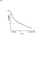
- FIG. 3 is a graph showing an example of the relationship between SOH and charge/discharge power control.
- FIG. 4 is a diagram showing vehicle registration of an electric vehicle.
- FIG. 5 is a diagram showing a procedure for a user to participate in V2G.
- FIG. 6 is a diagram showing an example of a V2G (including charging) control method using a charging plan.
- FIG. 7 is a diagram illustrating an example of a V2G control instruction by an application.
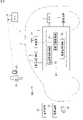
- FIG. 8 is a diagram showing another example of the outline of the charging/discharging system.
- An object of the present disclosure is to first suppress the progress of deterioration of the storage battery in order to provide an incentive to participate in supply and demand adjustment.
- Embodiments of the present disclosure include at least the following as gists thereof.
- This is a charger/discharger that is detachable from an electric vehicle and intervenes between the electric vehicle and the electric power system when attached to the electric vehicle, and is used for the storage battery mounted on the electric vehicle.
- a battery information acquisition unit that acquires state information
- a charge/discharge control unit that controls charging/discharging power between the storage battery and the power system, wherein the charge/discharge control unit controls based on the state information.
- a charger/discharger for controlling the charging/discharging power.
- the battery information acquisition unit acquires information on the voltage value, current value, humidity, and temperature of the storage battery from the electric vehicle, and at least one of the information Information on the degree of deterioration of the storage battery as the state information may be obtained based on one of the above.
- the internal resistance of the storage battery can be obtained based on the voltage value or current value after charging/discharging is switched. Since the rate of increase in internal resistance, humidity, and temperature (humidity and temperature in the storage battery) are physical quantities representing the state of deterioration of the storage battery, information on the degree of deterioration of the storage battery can be obtained based on these physical quantities.
- the charger/discharger of (2) above includes a vehicle information acquisition unit that acquires vehicle information including vehicle identification information of the electric vehicle, travel plan information, and desired discharge information to the electric power system.
- the charging/discharging control section may control the charging/discharging power based on the deterioration degree information and the vehicle information. In this case, V2G can be performed (or not performed) based on the user's travel plan and discharge request.
- the charge/discharge control unit obtains a period until the start of the next run from the travel plan information, and controls the charge/discharge power based on the period.
- the SOC of the storage battery can be in a better state when the next running is started.
- the charge/discharge control unit controls the charge/discharge power based on the period, and the SOC of the storage battery when the period is longer than a predetermined period of time, It is also possible to control the SOC to be lower than the SOC of the storage battery when the period is shorter than the predetermined period. As a result, the SOC of the storage battery can be adjusted based on the period until the user drives next time, and it is possible to satisfy both the improvement of convenience for the user and the suppression of progress of deterioration of the storage battery.
- the charge/discharge control unit controls the SOC of the storage battery to be equal to or lower than a predetermined threshold, and the predetermined threshold is 40. % or more and 60% or less. As a result, when the user does not drive for a while, progress of deterioration of the storage battery can be suppressed.
- this is a charging/discharging system in which an electric vehicle is electrically connected to a power system, and includes a battery information acquisition unit for acquiring information on the degree of deterioration of a storage battery mounted on the electric vehicle; and a charge/discharge control unit for controlling charging/discharging power between the electric vehicle and the electric power system; vehicle identification information of the electric vehicle; travel plan information; and a vehicle information acquisition unit that acquires the vehicle information, the charge/discharge control unit controls the charge/discharge power based on the deterioration degree information and the vehicle information, and the The information terminal is a charging/discharging system having a display for displaying the deterioration degree information, charging/discharging power information, and the SOC of the storage battery.
- charging/discharging power can be controlled based on information on the degree of deterioration of the storage battery and the user's driving plan for the electric vehicle.
- V2G can be performed while suppressing the progress of deterioration of the storage battery.
- the user can decide whether or not to participate in V2G by looking at the display of the information terminal.
- this is a charging/discharging system in which an electric vehicle is electrically connected to a power system, and includes a battery information acquiring unit for acquiring state information of a storage battery mounted on the electric vehicle; a charging/discharging control unit that controls charging/discharging power with a power system, wherein the charging/discharging control unit controls the charging/discharging power based on the state information.
- the charging/discharging power can be controlled based on the state information of the storage battery.
- V2G can be performed while suppressing the progress of deterioration of the storage battery.
- the battery information acquisition unit acquires information on the voltage value, current value, humidity, and temperature of the storage battery from the electric vehicle, and at least one of the information Information on the degree of deterioration of the storage battery as the state information may be obtained based on one of the above.
- the internal resistance of the storage battery can be obtained based on the voltage value or current value after charging/discharging is switched. Since the rate of increase in internal resistance, humidity, and temperature (humidity and temperature in the storage battery) are physical quantities representing the state of deterioration of the storage battery, information on the degree of deterioration of the storage battery can be obtained based on these physical quantities.
- the charging/discharging system of (9) above includes a vehicle information acquisition unit that acquires vehicle information including vehicle identification information of the electric vehicle, travel plan information, and desired discharge information to the power system.
- the charging/discharging control section may control the charging/discharging power based on the deterioration degree information and the vehicle information. In this case, V2G can be performed (or not performed) based on the user's travel plan and discharge request.
- junction box module With such a junction box module, it is possible to control the charging and discharging power based on the state information of the storage battery. As a result, V2G can be performed while suppressing the progress of deterioration of the storage battery.
- the battery information acquisition unit acquires information on the voltage value, current value, humidity, and temperature of the storage battery, and based on at least one of the information may acquire information on the degree of deterioration of the storage battery as the state information.
- the internal resistance of the storage battery can be obtained based on the voltage value or current value after charging/discharging is switched. Since the rate of increase in internal resistance, humidity, and temperature (humidity and temperature in the storage battery) are physical quantities representing the state of deterioration of the storage battery, information on the degree of deterioration of the storage battery can be obtained based on these physical quantities.
- the junction box module of (12) above comprising a vehicle information acquisition unit that acquires vehicle information including vehicle identification information of the electric vehicle, travel plan information, and desired discharge information to the electric power system.
- the charging/discharging control section may control the charging/discharging power based on the deterioration degree information and the vehicle information. In this case, V2G can be performed (or not performed) based on the user's travel plan and discharge request.
- this is a method for charging and discharging a storage battery by a charger/discharger when performing V2G by electrically connecting an electric vehicle to a power system, and the degree of deterioration of the storage battery mounted on the electric vehicle and controlling the charging/discharging power between the storage battery and the power system based on the information on the degree of deterioration.
- charging/discharging power can be controlled based on information on the degree of deterioration of the storage battery.
- V2G can be performed while suppressing the progress of deterioration of the storage battery.
- FIG. 1 is a diagram showing an outline of a charging/discharging system 100.
- the electric vehicle 1 includes a high-voltage battery pack 2, an inverter 3 connected to the high-voltage battery pack 2, a driving motor 4 connected to the inverter 3, a high-voltage load 5 connected to the high-voltage battery pack 2, a DC and an inlet 6.
- Examples of the high voltage load 5 include a DC/DC converter, an air conditioner compressor, and a heater.
- the high-voltage battery pack 2 includes a storage battery 7 , a battery management system 8 that monitors the storage battery 7 , and a high-voltage junction box module 9 provided between the storage battery 7 and the inverter 3 .
- the storage battery 7 is, for example, a lithium ion battery.
- the high-voltage junction box module 9 includes system main relays 9a and 9b, an inrush current suppression relay 9c, an inrush current suppression resistor 9d, a voltage sensor 9e, a current sensor 9f, a charge/discharge relay 9g, and a DC relay 9h. , an ECU 9j which is a control section of the high-voltage junction box module 9, and a current sensor 9n.
- a detection signal from the voltage sensor 9e, a detection signal from the current sensors 9f and 9n, and a signal from the battery management system 8 are sent to the ECU 9j.
- the ECU 9j controls opening and closing of the system main relays 9a and 9b, the inrush current suppression relay 9c, the charging/discharging relay 9g, and the DC relay 9h.
- the battery management system 8 sends detection signals of temperature and humidity in the storage battery 7 to the ECU 9j.
- the ECU 9j closes the system main relay 9a and the inrush current suppression relay 9c, then closes the system main relay 9b, and then opens the inrush current suppression relay 9c.
- the ECU 9j closes the system main relays 9a and 9b, and further closes the DC relay 9h, similarly to when the vehicle is running.
- the ECU 9j closes the charging/discharging relay 9g.
- the ECU 9j also closes the charging/discharging relay 9g when the storage battery 7 is discharged. If the system main relays 9a and 9b are also closed during charging and discharging, a DC voltage can be supplied to the high-voltage load 5.
- the DC relay 9h may be used for charging/discharging, and the configuration is not limited to that shown in FIG.
- the DC power supply line 9k is connected to the DC inlet 6.
- the ECU 9j and the DC inlet 6 are connected to each other by a CAN (Controller Area Network) communication line 9m.
- CAN Controller Area Network
- a consumer (house, etc.) 10 is provided with a dedicated outlet 11 from the electric power system 50, into which a plug 12 can be inserted.
- the charger/discharger 13 having the plug 12 includes, for example, an AC/DC power conversion section 131 and a communication section 132 .
- the charge/discharge connector 14 is connected to the power converter 131 via a cable 14a.
- the cable 14 a has a power line and a communication line, and the communication line is connected to the communication section 132 .
- the plug 12 is connected to the dedicated outlet 11 of the power system, and the charging/discharging connector 14 is attached to the DC inlet 6 .
- the charging/discharging connector 14 is attachable/detachable to/from the DC inlet 6, and the charging/discharging connector 14 is removed from the DC inlet 6 when the electric vehicle 1 is driven.
- the communication unit 132 of the charger/discharger 13 can wirelessly communicate with the server 15 .
- the server 15 can communicate with a higher-level aggregator (not shown). Power companies are above the aggregators. Servers and aggregators can also communicate with other customers in the area.
- the server 15 manages the energy of a consumer group capable of performing V2G, including the consumer 10.
- the server 15 requested by the aggregator to adjust the power supply and demand instructs the charging/discharging power value to the charger/discharger 13, and the electric vehicle 1 is charged/discharged with the instructed power value.
- the server 15 can communicate with the charger/discharger 13 .
- FIG. 2 is a diagram illustrating the internal configuration of the charger/discharger 13 in more detail.
- the charger/discharger 13 includes a control unit 133 and a power supply circuit 136 in addition to the power conversion unit 131 and the communication unit 132 described above.
- the control unit 133 has a battery information acquisition unit 134 and a charge/discharge control unit 135 as internal functions. Each process of the internal function of the control unit 133 can be realized by a processing circuit.
- the control unit 133 includes, for example, a processor, and the processor executes software (computer program) to implement necessary internal functions.
- the software is stored in a storage device (not shown) of control unit 133 .
- a power supply circuit 136 provides a control power supply voltage necessary for the power conversion unit 131 , the control unit 133 , and the communication unit 132 .
- the power conversion unit 131 performs charging or discharging operations under the control of the charge/discharge control unit 135 .
- the battery information acquisition unit 134 acquires battery information regarding the degree of deterioration of the storage battery based on information obtained from the electric vehicle via the charge/discharge connector 14 .
- the charge/discharge control unit 135 controls charge/discharge power based on information on the degree of deterioration.
- the charge/discharge control unit 135 also controls charge/discharge power based on information from the communication unit 132 .
- the charger/discharger 13 communicates with the server 15 .
- the server 15 has a vehicle information acquisition section 151 as an internal function.
- the server 15 can communicate with the information terminal 21 of the user 20 .
- the state quantity representing the degree of deterioration (soundness) of the storage battery is SOH (State of Health).
- SOH includes the capacity retention rate with respect to the fully charged capacity when the battery is new, and the increase rate of the internal resistance that increases with deterioration.
- physical quantities that can be relatively easily measured in a storage battery mounted on an electric vehicle are voltage, current, humidity, and temperature. Internal resistance can be determined based on voltage and current. If the internal resistance is known, the degree of deterioration of the storage battery can be estimated from the rate of increase.
- the charger/discharger 13 acquires each information of the voltage value detected by the voltage sensor 9e and the current value detected by the current sensor 9n in FIG. Find the resistance R. If this internal resistance is continuously obtained at a constant cycle, the increase rate of the internal resistance can be found. If the increase rate of the internal resistance is known, it is possible to obtain information on the corresponding degree of deterioration using, for example, a data table.
- the charger/discharger 13 obtains information on the degree of deterioration based on the provided calculation result. good.
- the charger/discharger 13 may simply obtain the information on the degree of deterioration. Based on the obtained deterioration degree information, control is performed to suppress the charge/discharge power of the storage battery that is more deteriorated. As a result, progress of deterioration of the storage battery can be suppressed.
- Humidity and temperature of the storage battery can be obtained by the charger/discharger 13 from the ECU 9j.
- Humidity and temperature also reflect the degree of degradation. Therefore, for example, when the humidity or temperature exceeds a threshold value, it is possible to control the charging/discharging power to a predetermined value or less (or prevent charging/discharging).
- FIG. 3 is a graph showing an example of the relationship between SOH and charge/discharge power control.
- the SOH is 100[%] when the storage battery is new, and when it reaches 60[%], for example, it is the limit of use.
- SOH is a certain value X, the charge/discharge power is controlled to P [kW].
- FIG. 4 is a diagram showing vehicle registration of the electric vehicle 1.
- the user 20 registers the vehicle using the vehicle body number, which is a number unique to the vehicle, from the information terminal 21 on which the dedicated application is installed.
- the aggregator 19 provides the information terminal 21 with a password associated with the vehicle body number.
- FIG. 5 is a diagram showing the procedure for a user to participate in V2G.
- the user 20 transmits the vehicle identification number and password of the V2G target vehicle from the information terminal 21 to the aggregator 19 or the server 15 to convey a request for V2G control.
- Aggregator 19 or server 15 recognizes the vehicle identification number and password and accepts the request.
- a vehicle body number is transmitted from the electric vehicle 1 (eg, main ECU) to the charger/discharger 13 and the aggregator 19 .
- the aggregator 19 or the server 15 recognizes V2G target vehicles and draws up a charging/discharging plan based on the user's request. Then, the aggregator 19 or the server 15 instructs the charger/discharger 13 to charge/discharge.
- FIG. 6 is a diagram showing an example of a V2G (including charging) control method using a charging plan. Assume that the following systems A, B, and C using electric vehicles exist in areas under the jurisdiction of the aggregator 19 and server 15 .
- system A has a high SOC, so it waits until the SOC drops to 50%, and when it reaches 50%, V2G is performed. After that, after one week has passed, the battery is fully charged by the timing of the next operation.
- System B is charged to SOC 50% and maintained at 50% for V2G control. Charge after 8 hours.
- V2G control is not performed, but charge/discharge is controlled so as to maintain an SOC of 50% in order to suppress deterioration of the storage battery.
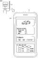
- FIG. 7 is a diagram illustrating an example of a V2G control instruction by an application.
- a screen as shown in the figure appears, showing a picture of the user's electric vehicle, the current battery state, whether or not V2G is being implemented, the date and time of the next car ride, and the period until then. etc. is displayed.
- the current state of the battery includes the degree of battery deterioration (SOH), state of charge (SOC), and temperature.
- vehicle information including vehicle identification information of the electric vehicle 1, travel plan information, and desired discharge information to the electric power system 50 can be provided to the vehicle information acquisition unit 151 (FIG. 2).
- the charge/discharge control unit 135 controls the charge/discharge power based on the deterioration degree information and the vehicle information. In this way, V2G can be performed (or not performed) based on the user's intention.
- the charge/discharge control unit 135 can obtain the period until the next run starts from the user's travel plan information, and can control the charge/discharge power based on the period. As a result, the SOC of the storage battery 7 can be brought into a better state when the next running is started.
- the charge/discharge control unit 135 controls the charge/discharge power to bring the SOC of the storage battery to a predetermined value based on whether the period until the start of the next run is longer or shorter than the predetermined period.
- the charge/discharge control unit 135 controls the SOC of the storage battery when the period until the next run is longer than the predetermined period is lower than the SOC of the storage battery when the period until the next run is shorter than the predetermined period. . If the period until the vehicle starts running is longer than the predetermined period, the SOC of the storage battery 7 is controlled to be equal to or less than a predetermined threshold.
- the predetermined threshold is, for example, 40% or more and 60% or less.
- the storage battery 7 progress of deterioration of the storage battery 7 can be suppressed when the user does not drive the electric vehicle for a while. If it is known that the vehicle will not be operated for a while, keeping the SOC of the storage battery 7 at about 50% will suppress deterioration. Furthermore, when the vehicle is not operated for a long period of time, it is preferable to set the SOC target to 50%, and while suppressing the charge/discharge power, follow the command value for adjusting the frequency of the electric power system and perform small charge/discharge operations.
- the predetermined time period can be, for example, 4 hours, 8 hours or 24 hours.
- the predetermined threshold may be 40% or more and 52% or less. As a result, progress of deterioration of the battery can be further suppressed.
- the SOC of the storage battery 7 is controlled to be 50% or more and 70% or less. As a result, the SOC of the storage battery 7 can be increased and the running ability can be increased by the time the user starts running.
- the high-voltage junction box module 9 has a control section 90 including a battery information acquisition section 91, a vehicle information acquisition section 92, and a charge/discharge control section 93.
- the vehicle information acquisition unit 92 may be in the server 15 .
- the motor 4, the high-voltage load 5, the storage battery 7, the battery management system 8, and the communication unit 22 are provided.
- Each process of the control unit 90 can be realized by a processing circuit.
- the control unit 90 includes, for example, a processor, and the processor executes software (computer program) to implement necessary internal functions.
- the software is stored in a storage device (not shown) of control unit 90 .
- the battery information acquisition unit 91 acquires state information from the storage battery 7 and the battery management system 8, and acquires battery information regarding the degree of deterioration of the storage battery 7 based on the state information.
- the charge/discharge control unit 93 controls charge/discharge power based on information on the degree of deterioration.
- the charging/discharging control unit 93 also controls charging/discharging power based on information obtained by the vehicle information acquisition unit 92 via the communication unit 22 of the electric vehicle.
- the communication unit 22 communicates with the server 15 .
- the server 15 can communicate with the information terminal 21 of the user 20 .
- the battery information acquisition unit 91 may control the charging/discharging power by transmitting control information for controlling the charging/discharging power to the charger/discharger 13 based on the deterioration degree information.
- Charging/discharging system 100 is configured by electrically connecting electric vehicle 1 to power system 50 .
- the charge/discharge system 100 includes a battery information acquisition unit 134 that acquires information on the degree of deterioration of the storage battery 7 mounted on the electric vehicle 1, and a charge/discharge control that controls charge/discharge power between the storage battery 7 and the power system 50. a portion 135; Then, the charge/discharge control unit 135 controls the charge/discharge power based on the deterioration degree information.
- charging/discharging power can be controlled based on information on the degree of deterioration of the storage battery 7 .
- V2G can be performed while suppressing the progress of deterioration of the storage battery 7 .
- This charger/discharger 13 includes a battery information acquisition unit 134 that acquires information on the degree of deterioration of the storage battery 7 mounted on the electric vehicle 1, and a charge/discharge unit that controls charge/discharge power between the storage battery 7 and the power system 50.
- a control unit 135 is provided. The charge/discharge control unit 135 controls charge/discharge power based on information on the degree of deterioration. Since such a charger/discharger is not mounted on the electric vehicle 1, it can contribute to weight reduction of the electric vehicle 1 accordingly.
- the charging/discharging system 100 can include a vehicle information acquisition unit 151 that acquires vehicle information including vehicle identification information of the electric vehicle, travel plan information, and desired discharge information to the electric power system 50 .
- the charge/discharge control unit 135 controls the charge/discharge power based on the deterioration degree information and the vehicle information.
- V2G it is possible to perform (or not perform) V2G based on not only the information on the degree of deterioration of the storage battery 7 but also the travel plan and discharge request of the user of the electric vehicle 1 .
- the information terminal 21 of the user 20 in addition to the battery information acquisition unit 134 and the charge/discharge control unit 135, vehicle identification information of the electric vehicle 1, travel plan information, and discharge request information to the power system 50 and a vehicle information acquisition unit 151 that acquires the vehicle information.
- the charge/discharge control unit 135 controls the charge/discharge power based on the deterioration degree information and the vehicle information, and the information terminal 21 has a display 17d that displays the deterioration degree information and the SOC of the storage battery.
- charge/discharge power can be controlled based on information on the degree of deterioration of the storage battery 7 and the travel plan of the user of the electric vehicle 1 .
- V2G can be performed while suppressing the progress of deterioration of the storage battery 7 .
- the user 20 can decide whether or not to participate in V2G by looking at the display 17d of the information terminal 21 .
- PHEV Plug-in Hybrid Electric Vehicle
- the processor may be, for example, a CPU.
- the processor is not limited to the CPU, and various processors such as GPU (Graphics Processing Unit) or DSP (Digital Signal Processor) can be used.
- the processor may be a hardware circuit based on ASIC.
- the processor may be configured by a plurality of CPUs, may be configured by a hardware circuit by a plurality of ASICs, or may be configured by a combination thereof.
- the storage device may be a semiconductor memory such as SRAM or DRAM, a register, or a magnetic storage device such as a hard disk device.
Landscapes
- Engineering & Computer Science (AREA)
- Power Engineering (AREA)
- Charge And Discharge Circuits For Batteries Or The Like (AREA)
Priority Applications (2)
| Application Number | Priority Date | Filing Date | Title |
|---|---|---|---|
| PCT/JP2021/025784 WO2023281698A1 (ja) | 2021-07-08 | 2021-07-08 | 充放電器、充放電システム、ジャンクションボックスモジュール、及び、蓄電池の充放電方法 |
| JP2023532981A JP7677428B2 (ja) | 2021-07-08 | 2021-07-08 | 充放電器、充放電システム、ジャンクションボックスモジュール、及び、蓄電池の充放電方法 |
Applications Claiming Priority (1)
| Application Number | Priority Date | Filing Date | Title |
|---|---|---|---|
| PCT/JP2021/025784 WO2023281698A1 (ja) | 2021-07-08 | 2021-07-08 | 充放電器、充放電システム、ジャンクションボックスモジュール、及び、蓄電池の充放電方法 |
Publications (1)
| Publication Number | Publication Date |
|---|---|
| WO2023281698A1 true WO2023281698A1 (ja) | 2023-01-12 |
Family
ID=84801662
Family Applications (1)
| Application Number | Title | Priority Date | Filing Date |
|---|---|---|---|
| PCT/JP2021/025784 Ceased WO2023281698A1 (ja) | 2021-07-08 | 2021-07-08 | 充放電器、充放電システム、ジャンクションボックスモジュール、及び、蓄電池の充放電方法 |
Country Status (2)
| Country | Link |
|---|---|
| JP (1) | JP7677428B2 (https=) |
| WO (1) | WO2023281698A1 (https=) |
Cited By (1)
| Publication number | Priority date | Publication date | Assignee | Title |
|---|---|---|---|---|
| DE102023122517A1 (de) * | 2023-08-23 | 2025-02-27 | Bayerische Motoren Werke Aktiengesellschaft | Bestimmen eines Gesundheitszustands eines Hochvoltspeichers eines Elektrofahrzeugs |
Citations (4)
| Publication number | Priority date | Publication date | Assignee | Title |
|---|---|---|---|---|
| JPH08254573A (ja) * | 1995-03-15 | 1996-10-01 | Omron Corp | バッテリー計測装置 |
| JP2015106962A (ja) * | 2013-11-29 | 2015-06-08 | 株式会社デンソー | 充放電制御装置及び充放電システム |
| WO2021038762A1 (ja) * | 2019-08-28 | 2021-03-04 | 三菱電機株式会社 | 充放電制御装置、蓄電システムおよび充放電制御方法 |
| JP2021044860A (ja) * | 2019-09-06 | 2021-03-18 | 日産自動車株式会社 | 全固体リチウムイオン二次電池システム、および全固体リチウムイオン二次電池用充電装置 |
-
2021
- 2021-07-08 WO PCT/JP2021/025784 patent/WO2023281698A1/ja not_active Ceased
- 2021-07-08 JP JP2023532981A patent/JP7677428B2/ja active Active
Patent Citations (4)
| Publication number | Priority date | Publication date | Assignee | Title |
|---|---|---|---|---|
| JPH08254573A (ja) * | 1995-03-15 | 1996-10-01 | Omron Corp | バッテリー計測装置 |
| JP2015106962A (ja) * | 2013-11-29 | 2015-06-08 | 株式会社デンソー | 充放電制御装置及び充放電システム |
| WO2021038762A1 (ja) * | 2019-08-28 | 2021-03-04 | 三菱電機株式会社 | 充放電制御装置、蓄電システムおよび充放電制御方法 |
| JP2021044860A (ja) * | 2019-09-06 | 2021-03-18 | 日産自動車株式会社 | 全固体リチウムイオン二次電池システム、および全固体リチウムイオン二次電池用充電装置 |
Cited By (1)
| Publication number | Priority date | Publication date | Assignee | Title |
|---|---|---|---|---|
| DE102023122517A1 (de) * | 2023-08-23 | 2025-02-27 | Bayerische Motoren Werke Aktiengesellschaft | Bestimmen eines Gesundheitszustands eines Hochvoltspeichers eines Elektrofahrzeugs |
Also Published As
| Publication number | Publication date |
|---|---|
| JP7677428B2 (ja) | 2025-05-15 |
| JPWO2023281698A1 (https=) | 2023-01-12 |
Similar Documents
| Publication | Publication Date | Title |
|---|---|---|
| JP7251503B2 (ja) | 電力管理装置、及び電力管理方法 | |
| US11400832B2 (en) | Electrically powered vehicle | |
| CN113752900B (zh) | 蓄电系统以及车辆 | |
| US12101052B2 (en) | Electric vehicle control system, control method, and computer-readable storage medium | |
| CN106945484B (zh) | 一种电动车辆中空调的控制方法、系统及电动车辆 | |
| CN102510816B (zh) | 车辆以及车辆的控制方法 | |
| US20210053459A1 (en) | Electric power system and vehicle | |
| EP3865889A1 (en) | Battery diagnosis apparatus and vehicle | |
| CN112124143A (zh) | 控制系统、控制方法及存储介质 | |
| JP7291513B2 (ja) | 車両 | |
| JP2014090578A (ja) | 車両の電源装置 | |
| JP2021158905A (ja) | 制御装置、診断システム、制御方法、及びプログラム | |
| CN116394797A (zh) | 一种电动汽车高电压平台充电系统及方法 | |
| CN114801748B (zh) | 车辆高压上下电控制方法、装置、车辆及存储介质 | |
| CN105452051B (zh) | 用于运行蓄电池系统的方法 | |
| JP7512947B2 (ja) | 充電制御装置、及び車両 | |
| JP7677428B2 (ja) | 充放電器、充放電システム、ジャンクションボックスモジュール、及び、蓄電池の充放電方法 | |
| CN116461382A (zh) | 车辆电池的控制 | |
| JP6245120B2 (ja) | 電動車両の制御装置 | |
| JP2022148243A (ja) | 車両 | |
| CN112054257B (zh) | 一种动力电池充放电控制方法及装置 | |
| JP2015063174A (ja) | ハイブリッド車両の制御装置 | |
| CN117507941A (zh) | 电力系统、控制装置、以及电力系统的控制方法 | |
| US20250050774A1 (en) | Charging system and vehicle | |
| WO2023119525A1 (ja) | 充放電システム、電力中継装置、及び、電力中継方法 |
Legal Events
| Date | Code | Title | Description |
|---|---|---|---|
| 121 | Ep: the epo has been informed by wipo that ep was designated in this application |
Ref document number: 21949331 Country of ref document: EP Kind code of ref document: A1 |
|
| WWE | Wipo information: entry into national phase |
Ref document number: 2023532981 Country of ref document: JP |
|
| NENP | Non-entry into the national phase |
Ref country code: DE |
|
| 122 | Ep: pct application non-entry in european phase |
Ref document number: 21949331 Country of ref document: EP Kind code of ref document: A1 |