WO2023277115A1 - 車両の後部構造 - Google Patents
車両の後部構造 Download PDFInfo
- Publication number
- WO2023277115A1 WO2023277115A1 PCT/JP2022/026148 JP2022026148W WO2023277115A1 WO 2023277115 A1 WO2023277115 A1 WO 2023277115A1 JP 2022026148 W JP2022026148 W JP 2022026148W WO 2023277115 A1 WO2023277115 A1 WO 2023277115A1
- Authority
- WO
- WIPO (PCT)
- Prior art keywords
- vehicle
- battery
- vertical wall
- wall portion
- width direction
- Prior art date
Links
- 239000008151 electrolyte solution Substances 0.000 claims abstract description 8
- 230000002093 peripheral effect Effects 0.000 claims description 5
- 230000000149 penetrating effect Effects 0.000 claims description 3
- 239000003792 electrolyte Substances 0.000 description 13
- 230000004308 accommodation Effects 0.000 description 3
- 238000004140 cleaning Methods 0.000 description 3
- 239000012530 fluid Substances 0.000 description 3
- QAOWNCQODCNURD-UHFFFAOYSA-N Sulfuric acid Chemical compound OS(O)(=O)=O QAOWNCQODCNURD-UHFFFAOYSA-N 0.000 description 2
- 230000004888 barrier function Effects 0.000 description 2
- 238000012986 modification Methods 0.000 description 2
- 230000004048 modification Effects 0.000 description 2
- 229920003051 synthetic elastomer Polymers 0.000 description 2
- 239000005061 synthetic rubber Substances 0.000 description 2
- 229920002943 EPDM rubber Polymers 0.000 description 1
- 229910000831 Steel Inorganic materials 0.000 description 1
- 238000013459 approach Methods 0.000 description 1
- 239000011248 coating agent Substances 0.000 description 1
- 238000000576 coating method Methods 0.000 description 1
- 238000005336 cracking Methods 0.000 description 1
- 230000007423 decrease Effects 0.000 description 1
- 238000010586 diagram Methods 0.000 description 1
- 239000011244 liquid electrolyte Substances 0.000 description 1
- 239000002184 metal Substances 0.000 description 1
- 229920005989 resin Polymers 0.000 description 1
- 239000011347 resin Substances 0.000 description 1
- 230000000630 rising effect Effects 0.000 description 1
- 239000010959 steel Substances 0.000 description 1
- 229920003002 synthetic resin Polymers 0.000 description 1
- 239000000057 synthetic resin Substances 0.000 description 1
Images


Classifications
-
- B—PERFORMING OPERATIONS; TRANSPORTING
- B60—VEHICLES IN GENERAL
- B60K—ARRANGEMENT OR MOUNTING OF PROPULSION UNITS OR OF TRANSMISSIONS IN VEHICLES; ARRANGEMENT OR MOUNTING OF PLURAL DIVERSE PRIME-MOVERS IN VEHICLES; AUXILIARY DRIVES FOR VEHICLES; INSTRUMENTATION OR DASHBOARDS FOR VEHICLES; ARRANGEMENTS IN CONNECTION WITH COOLING, AIR INTAKE, GAS EXHAUST OR FUEL SUPPLY OF PROPULSION UNITS IN VEHICLES
- B60K1/00—Arrangement or mounting of electrical propulsion units
- B60K1/04—Arrangement or mounting of electrical propulsion units of the electric storage means for propulsion
-
- B—PERFORMING OPERATIONS; TRANSPORTING
- B60—VEHICLES IN GENERAL
- B60R—VEHICLES, VEHICLE FITTINGS, OR VEHICLE PARTS, NOT OTHERWISE PROVIDED FOR
- B60R16/00—Electric or fluid circuits specially adapted for vehicles and not otherwise provided for; Arrangement of elements of electric or fluid circuits specially adapted for vehicles and not otherwise provided for
- B60R16/02—Electric or fluid circuits specially adapted for vehicles and not otherwise provided for; Arrangement of elements of electric or fluid circuits specially adapted for vehicles and not otherwise provided for electric constitutive elements
- B60R16/04—Arrangement of batteries
-
- B—PERFORMING OPERATIONS; TRANSPORTING
- B60—VEHICLES IN GENERAL
- B60R—VEHICLES, VEHICLE FITTINGS, OR VEHICLE PARTS, NOT OTHERWISE PROVIDED FOR
- B60R5/00—Compartments within vehicle body primarily intended or sufficiently spacious for trunks, suit-cases, or the like
- B60R5/04—Compartments within vehicle body primarily intended or sufficiently spacious for trunks, suit-cases, or the like arranged at rear of vehicle
-
- B—PERFORMING OPERATIONS; TRANSPORTING
- B62—LAND VEHICLES FOR TRAVELLING OTHERWISE THAN ON RAILS
- B62D—MOTOR VEHICLES; TRAILERS
- B62D25/00—Superstructure or monocoque structure sub-units; Parts or details thereof not otherwise provided for
- B62D25/20—Floors or bottom sub-units
-
- H—ELECTRICITY
- H01—ELECTRIC ELEMENTS
- H01M—PROCESSES OR MEANS, e.g. BATTERIES, FOR THE DIRECT CONVERSION OF CHEMICAL ENERGY INTO ELECTRICAL ENERGY
- H01M50/00—Constructional details or processes of manufacture of the non-active parts of electrochemical cells other than fuel cells, e.g. hybrid cells
- H01M50/20—Mountings; Secondary casings or frames; Racks, modules or packs; Suspension devices; Shock absorbers; Transport or carrying devices; Holders
- H01M50/244—Secondary casings; Racks; Suspension devices; Carrying devices; Holders characterised by their mounting method
-
- H—ELECTRICITY
- H01—ELECTRIC ELEMENTS
- H01M—PROCESSES OR MEANS, e.g. BATTERIES, FOR THE DIRECT CONVERSION OF CHEMICAL ENERGY INTO ELECTRICAL ENERGY
- H01M50/00—Constructional details or processes of manufacture of the non-active parts of electrochemical cells other than fuel cells, e.g. hybrid cells
- H01M50/20—Mountings; Secondary casings or frames; Racks, modules or packs; Suspension devices; Shock absorbers; Transport or carrying devices; Holders
- H01M50/249—Mountings; Secondary casings or frames; Racks, modules or packs; Suspension devices; Shock absorbers; Transport or carrying devices; Holders specially adapted for aircraft or vehicles, e.g. cars or trains
-
- Y—GENERAL TAGGING OF NEW TECHNOLOGICAL DEVELOPMENTS; GENERAL TAGGING OF CROSS-SECTIONAL TECHNOLOGIES SPANNING OVER SEVERAL SECTIONS OF THE IPC; TECHNICAL SUBJECTS COVERED BY FORMER USPC CROSS-REFERENCE ART COLLECTIONS [XRACs] AND DIGESTS
- Y02—TECHNOLOGIES OR APPLICATIONS FOR MITIGATION OR ADAPTATION AGAINST CLIMATE CHANGE
- Y02E—REDUCTION OF GREENHOUSE GAS [GHG] EMISSIONS, RELATED TO ENERGY GENERATION, TRANSMISSION OR DISTRIBUTION
- Y02E60/00—Enabling technologies; Technologies with a potential or indirect contribution to GHG emissions mitigation
- Y02E60/10—Energy storage using batteries
Definitions
- This invention relates to the rear structure of a vehicle.
- Cars are equipped with batteries that supply power to electrical components such as lamps and air conditioners.
- This battery is often mounted in the engine room at the front of the vehicle, but may be mounted in the cargo box at the rear of the vehicle depending on the layout (for example, Patent Document 1).
- Batteries are roughly divided into wet batteries that contain electrolyte in a fluid state, and dry batteries that contain sheets, etc. that absorb the electrolyte into a non-flowing state.
- the wet battery hereinafter simply referred to as the "battery”
- the cargo box and the battery installed in the cargo box will be damaged in the event of an accident in which the following vehicle collides with the own vehicle. It may be damaged.
- the battery must be placed at a biased position on one side in the vehicle width direction within the cargo box.
- the distance from the battery to the vehicle interior outside the cargo box is short, so when the battery is damaged as described above, the electrolyte in the battery may splash into the vehicle interior.
- the present invention has been made in view of the above problems, and its object is to prevent damage to a cargo box and a battery mounted in the cargo box when a following vehicle collides with the own vehicle, and to prevent the collision.
- the present invention provides a vehicle rear portion structure having the following configuration. a rear floor panel arranged at the rear of the vehicle; a battery disposed at a position biased to one side of the upper surface of the rear floor panel in the vehicle width direction and containing an electrolytic solution; a top plate covering the battery from above; an end plate extending downward from one end of the top plate in the vehicle width direction; a vertical wall portion integrally formed to protrude to the side; and rear structure of a vehicle with a
- the vertical wall portion may adopt a configuration in which the upper surface side of the top plate is formed in the shape of a hollow box that is open.
- the lower end portion of the vertical wall portion may be bifurcated in the longitudinal direction of the vehicle.
- the lower end of the end plate is formed with a notch that penetrates in the vehicle width direction at a position that overlaps with the space between the two forks of the lower end of the vertical wall when viewed from the vehicle width direction. can do.
- the vertical wall portion may have a stepped shape in which an upper portion of the vertical wall portion protrudes toward the battery with respect to a lower portion of the vertical wall portion when viewed from the vehicle front-rear direction.
- a configuration may be adopted in which the end of the upper portion of the vertical wall portion on the other side in the vehicle width direction is arranged closer to the battery than the position of the outer peripheral edge of the battery tray.
- the vertical wall portion may have a shape that protrudes toward the battery side from the front side toward the rear side in the vehicle front-rear direction when viewed in the vertical direction.
- the end plate can adopt a configuration in which it is arranged in the vehicle width direction so as to face the quarter trim that constitutes the side surface of the luggage compartment at the rear of the vehicle.
- a configuration may be adopted in which the end plate and the vertical wall portion are arranged directly above at least one of the pair of side members.
- the one side member has a pair of side walls facing each other in the vehicle width direction and a bottom wall connecting the lower ends of the pair of side walls,
- the vertical wall portion is arranged directly above the side wall of the pair of side walls that is closer to the battery,
- the end plate may be arranged directly above the side wall of the pair of side walls farther from the battery.
- the vertical wall portion is integrally formed downward from the top plate.
- the rigidity of the cargo box itself can be increased, so damage to the cargo box when the following vehicle collides with the own vehicle and damage to the battery caused by the damage to the cargo box can be prevented.
- a vertical wall portion and an end plate are provided on one outer side of the battery in the vehicle width direction. Therefore, due to the layout, the battery must be placed in a biased position on one side in the vehicle width direction. Even so, the vertical wall portion and the end plate act as a barrier to prevent the electrolytic solution from splashing into the passenger compartment.
- FIG. 2 is a diagram schematically showing a state in which the tailgate of a vehicle employing the vehicle rear portion structure of the embodiment of the present invention is opened to open the luggage compartment at the rear portion of the vehicle;
- the figure which looked at the luggage compartment of the vehicle rear part shown in FIG. 1 from upper direction Partial cross-sectional view showing a state in which the cargo lid shown in FIG. 2 is removed Sectional view along IV-IV line in FIG. Enlarged view near the battery in FIG.
- Cross-sectional view along line VII-VII in FIG. 3 is an exploded perspective view of the cargo box shown in FIG.
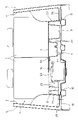
- FIG. 1 schematically shows a state in which a tailgate (not shown) for opening and closing a luggage compartment 1 at the rear of a vehicle is opened to open the luggage compartment 1 .
- the luggage compartment 1 is an interior space behind the rear seat 2 in the longitudinal direction of the vehicle.
- the left quarter trim 3 constitutes the left side of the luggage compartment 1
- the right quarter trim 4 constitutes the right side of the luggage compartment 1 .
- the quarter trims 3 and 4 are interior members provided along the inner surface of the body 5 at the rear portion of the vehicle.
- a cargo box 6 and a cargo lid 7 covering the upper surface of the cargo box 6 are provided in the lower part of the luggage compartment 1 (see FIG. 1).
- the cargo box 6 is arranged between the rear seat 2 and the rear end panel 8 facing each other in the longitudinal direction of the vehicle.
- the upper surface of the cargo box 6 is formed with a storage recess 9 capable of storing luggage such as tools and cleaning supplies.
- the cargo lid 7 (see FIG. 2) is supported so as to be able to swing up and down with the front end of the cargo lid 7 in the longitudinal direction of the vehicle as a fulcrum.
- the cargo lid 7 on the cargo box 6 By overlapping the cargo lid 7 on the cargo box 6, the accommodation recess 9 on the upper surface of the cargo box 6 can be closed. Further, by lifting the cargo lid 7 upward, the accommodation recess 9 on the upper surface of the cargo box 6 can be opened.
- the rear portion of the vehicle is provided with a pair of left and right side members 10, 11 extending in the longitudinal direction of the vehicle, and a rear floor panel 12 supported from below by the pair of side members 10, 11. ing.
- the pair of side members 10 and 11 are arranged symmetrically with respect to the center in the vehicle width direction (horizontal direction of the vehicle).
- a lower surface of the rear floor panel 12 is fixed to upper surfaces of the side members 10 and 11 .
- the side member 10 has a C-shaped cross section having a pair of side walls 13 and 14 facing each other in the vehicle width direction and a bottom wall 15 connecting the lower ends of the pair of side walls 13 and 14 to each other. It is steel.
- a battery 16 is provided between the rear floor panel 12 and the cargo box 6 as shown in FIG.
- the battery 16 is a wet battery containing electrolyte in a fluid state.
- the battery 16 is arranged on the upper surface of the rear floor panel 12 at a position biased to one side (left side in the figure) in the vehicle width direction. In the drawing, the battery 16 is arranged so as to exist only on one side (left side in the drawing) of the upper surface of the rear floor panel 12 with respect to the central position of the rear floor panel 12 in the vehicle width direction.
- the cargo box 6 is composed of a top plate 20 disposed facing above the rear floor panel 12 so as to cover the battery 16 from above, and a top plate 20 extending downward from one end (left side in the figure) of the top plate 20 in the vehicle width direction.
- a first end plate 21 extending, a second end plate 22 extending downward from the end of the top plate 20 on the other side (right side in the figure) in the vehicle width direction, and the first end plate 21 and the battery from the top plate 20 and a box wall portion 24 extending downward from the top plate 20 through between the second end plate 22 and the battery 16 .
- the box wall portion 24 is formed in a hollow box shape with an open upper surface side of the top plate 20 so as to form the accommodation recess 9 (see FIGS. 2 and 3) inside the box wall portion 24 .
- a cargo lid 7 is superimposed on the upper surface of the top plate 20 so as to close the upper end opening of the box wall portion 24 .
- the first end plate 21 is formed integrally with the top plate 20
- the second end plate 22 is also formed integrally with the top plate 20
- the first end plate 21 is arranged to face the left quarter trim 3 in the vehicle width direction
- the second end plate 22 is also arranged to face the right quarter trim 4 in the vehicle width direction.
- the lower end of the first end plate 21 is supported by a horizontal portion 25 integrally formed with the lower end of the left quarter trim 3
- the lower end of the second end plate 22 is also integrally formed with the lower end of the right quarter trim 4 . It is supported by the formed horizontal portion 26 .
- the lower end of the first end plate 21 and the lower end of the second end plate 22 may be directly supported by the rear floor panel 12 .
- the vertical wall portion 23 is also formed in the shape of a hollow box whose upper surface side of the top plate 20 is open, so that tools, cleaning supplies, and other articles can be accommodated therein. .
- the box wall portion 24 integrally protrudes downward from the top plate 20
- the vertical wall portion 23 also integrally protrudes downward from the top plate 20 .
- the cargo box 6 including the top plate 20, the first end plate 21, the second end plate 22, the box wall portion 24, and the vertical wall portion 23 can be made of synthetic resin or synthetic rubber. If the cargo box 6 is made of synthetic rubber (e.g., ethylene propylene diene rubber), it is possible to reliably prevent the cargo box 6 from cracking when a following vehicle collides with the own vehicle.
- the battery 16 has a battery case 27 , a lid 28 provided on the upper end of the battery case 27 , and a pair of terminals 29 provided on the lid 28 .
- the battery container 27 contains a liquid electrolyte and electrodes (not shown) immersed in the electrolyte. Dilute sulfuric acid can be used as the electrolytic solution.
- a battery harness 30 is connected to each terminal 29 provided on the lid 28 .
- the battery 16 outputs a DC voltage of 12 V and supplies electric power to electrical equipment such as vehicle lamps and an air conditioner.
- a battery cover 31 that protects the battery 16 is attached to the battery 16 .
- a portion of the top plate 20 of the cargo box 6 located directly above the battery 16 serves as a battery service hole cover 33 .
- the battery service hole 32 penetrating vertically through the top plate 20 can be opened and closed.
- a battery tray 34 is provided between the battery 16 and the rear floor panel 12 to receive and support the lower surface of the battery 16 .
- the battery tray 34 has a tray bottom portion 35 on which the batteries 16 are placed, and a tray peripheral wall portion 36 rising from the peripheral edge of the tray bottom portion 35 .
- the battery tray 34 is fitted into a battery tray fitting recess 37 formed in the upper surface of the rear floor panel 12 .
- the battery tray 34 is made of resin or metal coated with an antirust coating so that it will not corrode even if the electrolyte of the battery 16 adheres to it.
- the vertical wall portion 23 is provided so as to cover the entire length of the battery 16 in the vehicle front-rear direction when viewed from the vehicle width direction. That is, the length of the vertical wall portion 23 in the vehicle front-rear direction is set longer than the length of the battery 16 in the vehicle front-rear direction, and the front end of the vertical wall portion 23 in the vehicle front-rear direction coincides with the front end of the battery 16 in the vehicle front-rear direction.
- the vertical wall portion 23 is provided such that the rear end of the vertical wall portion 23 in the vehicle front-rear direction is positioned rearward of the rear end of the battery 16 in the vehicle front-rear direction.
- the lower end portion of the vertical wall portion 23 is formed in two halves in the vehicle front-rear direction, and a space penetrating in the vehicle width direction is formed between the two tines.
- the lower end of the first end plate 21 is provided at a position overlapping the space between the two forks of the lower end of the vertical wall portion 23 when viewed in the vehicle width direction.
- a through notch 38 is formed.
- the battery harness 30 connected to the terminal 29 of the battery 16 is separated from the space between the two forks at the lower end of the vertical wall portion 23 and the notch at the lower end of the first end plate 21 . 38 in order.
- the vertical wall portion 23 has an upper portion 23 a that protrudes toward the battery 16 with respect to a lower portion 23 b of the vertical wall portion 23 when viewed from the vehicle front-rear direction. It has a stepped shape that That is, the upper portion 23a of the vertical wall portion 23 has a surface facing the battery 16 at a position closer to the battery 16 in the vehicle width direction than the surface facing the battery 16 of the lower portion 23b of the vertical wall portion 23. .
- the lower end of the surface of the upper portion 23a of the vertical wall portion 23 facing the battery 16 and the upper end of the surface of the lower portion 23b of the vertical wall portion 23 facing the battery 16 are connected via a horizontal stepped portion 23c. there is As shown in FIG.
- the end of the upper portion 23 a of the vertical wall portion 23 on the other side in the vehicle width direction (the right side in the figure) is positioned closer to the battery 16 than the position of the outer peripheral edge of the battery tray 34 . is located on the side closest to the
- the upper portion 23a of the vertical wall portion 23 has a shape that protrudes toward the battery 16 from the front side toward the rear side in the vehicle front-rear direction (a shape that approaches the battery 16) when viewed from the vertical direction.
- the width dimension in the vehicle width direction of the upper portion 23a of the vertical wall portion 23 gradually increases from the front side toward the rear side in the vehicle longitudinal direction.
- Vertical wall portions 23 are formed so that the distance between them gradually decreases.
- the first end plate 21 and the vertical wall portion 23 of the cargo box 6 are arranged directly above the side member 10 . That is, the first end plate 21 is arranged so as to have a portion overlapping the side member 10 when viewed in the vertical direction. 10 are arranged so as to have overlapping portions.
- the vertical wall portion 23 is arranged directly above the side wall 14 of the pair of side walls 13 and 14 of the side member 10 that is closer to the battery 16 .
- the first end plate 21 is arranged directly above the side wall 13 of the pair of side walls 13 and 14 of the side member 10 farther from the battery 16 .
- FIG. A vertical wall portion 23 formed integrally with the top plate 20 of the cargo box 6 is provided between the battery 16 located on the left side in the width direction. Therefore, when the following vehicle collides with the own vehicle and the battery 16 is damaged, the electrolyte that scatters from the battery 16 to the left side in the vehicle width direction can be dissipated from the vertical wall portion 23 of the cargo box 6 before the scattering spreads. can accept. Therefore, when the following vehicle collides with the own vehicle and the battery 16 mounted on the rear part of the vehicle is damaged, it is possible to prevent the electrolyte from the battery 16 from scattering.
- a vertical wall portion 23 and a first end plate 21 are provided on the outer side of the battery 16 in one of the vehicle width directions (the left direction in the drawing). Therefore, due to the layout, the battery 16 must be placed at a biased position on one side (left side in the figure) in the vehicle width direction. Even if the battery 16 is damaged by an impact or the like, the vertical wall portion 23 and the first end plate 21 act as a barrier to prevent the electrolyte from splashing into the passenger compartment.
- the structural rigidity of the cargo box 6 can be increased by the hollow box-shaped vertical wall portion 23 formed integrally with the top plate 20 .
- the vertical wall portion 23 of the cargo box 6 is formed in the shape of a hollow box in which the upper surface side of the top plate 20 is open. It is possible to store loads such as tools and cleaning supplies not only in the storage recess 9 shown, but also in the vertical wall portion 23, so that a large number of loads can be stored.
- the lower end portion of the vertical wall portion 23 is formed to be bifurcated in the vehicle front-rear direction.
- a battery harness 30 for drawing power from the battery 16 can be wired through the space between the two branches at the lower end of the vertical wall portion 23 .
- the battery harness 30 can be protected by the vertical wall portion 23, and disconnection of the battery harness 30 can be prevented.
- the upper portion 23a of the vertical wall portion 23 faces the lower portion 23b of the vertical wall portion 23 when viewed from the vehicle front-rear direction. Since the vertical wall portion 23 having a stepped shape protruding toward the battery 16 is adopted, the upper portion 23a of the vertical wall portion 23 is arranged relatively close to the battery 16, and the electrolyte splashing from the upper portion of the battery 16 is prevented. can be effectively received by the upper portion 23a of the vertical wall portion 23 before the scattering spreads. Further, since the lower portion 23b of the vertical wall portion 23 is arranged relatively far from the battery 16, other members (for example, the battery harness 30, etc.) are placed between the lower portion 23b of the vertical wall portion 23 and the battery 16. It is possible to secure the placement space.
- other members for example, the battery harness 30, etc.
- the vertical wall portion 23 has a shape that protrudes toward the battery 16 as it goes from the front side to the rear side in the vehicle front-rear direction. At the rear portion of the battery 16 in the vehicle front-rear direction, the gap between the battery 16 and the vertical wall portion 23 is narrowed, thereby effectively suppressing splashing of the electrolyte from the battery 16 .
- the gap between the battery 16 and the vertical wall portion 23 is relatively widened, so that the vertical wall portion 23 and the battery 16, it is possible to secure an arrangement space for other members (for example, the battery harness 30, a fusible link (not shown), etc.).
- the vehicle rear portion structure of this embodiment includes the first end plate 21 and the first end plate 21 of the cargo box 6 directly above the side member 10 having high rigidity against external force acting in the longitudinal direction of the vehicle. Since the vertical wall portion 23 is positioned, it is possible to suppress deformation of the first end plate 21 and the vertical wall portion 23 of the cargo box 6 when the following vehicle collides with the host vehicle. Therefore, the electrolytic solution that scatters from the battery 16 can be reliably received by the first end plate 21 and the vertical wall portion 23 of the cargo box 6 .
- the battery 16 is arranged on the left side of the rear floor panel 12 in the vehicle width direction. It is also possible to place it in a different position. In this case, the left and right configurations of the above embodiment may be interchanged.
Landscapes
- Engineering & Computer Science (AREA)
- Chemical & Material Sciences (AREA)
- Mechanical Engineering (AREA)
- Combustion & Propulsion (AREA)
- Transportation (AREA)
- Chemical Kinetics & Catalysis (AREA)
- Electrochemistry (AREA)
- General Chemical & Material Sciences (AREA)
- Aviation & Aerospace Engineering (AREA)
- Battery Mounting, Suspending (AREA)
- Body Structure For Vehicles (AREA)
Abstract
車両の後部構造は、車両後部に配置されるリヤフロアパネルと、リヤフロアパネルの上面の車幅方向の一方側に偏った位置に配置され、電解液を収容したバッテリと、バッテリを上側から覆う天板と、天板の車幅方向の一方側の端部から下方に延びる端板と、端板とバッテリとの間に設けられ、天板から下側へ一体に突出形成された縦壁部と、を有するカーゴボックスと、を備える。
Description
この発明は、車両の後部構造に関する。
自動車には、ランプ類やエアコン等の電装品に電力を供給するバッテリが搭載される。このバッテリは、車両前部のエンジンルーム内に搭載されることが多いが、レイアウトによっては、車両後部のカーゴボックス内に搭載される場合もある(例えば、特許文献1)。
バッテリは、電解液を流動状態で収容したウェットバッテリと、電解液をシート等に吸収させて非流動状態にし、そのシート等を収容したドライバッテリと、に大別される。このうちウェットバッテリ(以下単に「バッテリ」という)を車両後部の荷室に搭載した場合、後続車両が自車両に衝突する事故が起きたときに、カーゴボックスおよびカーゴボックス内に搭載されたバッテリが破損することがある。
また、レイアウトの関係上、カーゴボックス内における車幅方向一方側の偏った位置にバッテリを配置しなければならない車両がある。このような車両では、バッテリからカーゴボックスの外側の車室内までの距離が近くなるため、上記のようにバッテリが破損した際、当該バッテリ内の電解液が車室内まで飛散するおそれがある。
この発明は、上記課題に鑑みてなされたものであって、その目的は、後続車両が自車両に衝突した際のカーゴボックスおよびカーゴボックス内に搭載されたバッテリの破損を防止するとともに、上記衝突の衝撃等によりバッテリの破損が生じた場合であっても、車室内への電解液の飛散を防止することができる車両の後部構造を提供することである。
上記課題を解決するため、この発明では、以下の構成の車両の後部構造を提供する。
車両後部に配置されるリヤフロアパネルと、
前記リヤフロアパネルの上面の車幅方向の一方側に偏った位置に配置され、電解液を収容したバッテリと、
前記バッテリを上側から覆う天板と、前記天板の車幅方向の前記一方側の端部から下方に延びる端板と、前記端板と前記バッテリとの間に設けられ、前記天板から下側へ一体に突出形成された縦壁部と、を有するカーゴボックスと、
を備えた車両の後部構造。
車両後部に配置されるリヤフロアパネルと、
前記リヤフロアパネルの上面の車幅方向の一方側に偏った位置に配置され、電解液を収容したバッテリと、
前記バッテリを上側から覆う天板と、前記天板の車幅方向の前記一方側の端部から下方に延びる端板と、前記端板と前記バッテリとの間に設けられ、前記天板から下側へ一体に突出形成された縦壁部と、を有するカーゴボックスと、
を備えた車両の後部構造。
前記縦壁部は、前記天板の上面側が開放された中空箱状に形成されている構成を採用することができる。
前記縦壁部の下端部は、車両前後方向に二股に分かれて形成されている構成を採用することができる。
前記端板の下端部には、車幅方向から見て、前記縦壁部の下端部の二股の間の空間と重なる位置に、車幅方向に貫通する切欠きが形成されている構成を採用することができる。
前記縦壁部は、車両前後方向から見て、前記縦壁部の上側部分が前記縦壁部の下側部分に対して前記バッテリに向かって突出する段差形状を有する構成を採用することができる。
前記バッテリと前記リヤフロアパネルとの間に設けられ、前記バッテリの下面を受け支えるバッテリトレイをさらに備え、
前記縦壁部の上側部分の車幅方向他方側の端は、前記バッテリトレイの外周縁の位置よりも前記バッテリに近い側に配置されている構成を採用することができる。
前記縦壁部の上側部分の車幅方向他方側の端は、前記バッテリトレイの外周縁の位置よりも前記バッテリに近い側に配置されている構成を採用することができる。
前記縦壁部は、鉛直方向から見たときに、車両前後方向の前側から後側に向かうほど前記バッテリ側に突出する形状を有する構成を採用することができる。
前記端板は、車両後部の荷室側面を構成するクォータートリムと車幅方向に対向して配置されている構成を採用することができる。
前記リヤフロアパネルを下側から支持し、車両前後方向に延びる一対のサイドメンバをさらに有し、
前記端板および前記縦壁部は、前記一対のサイドメンバのうちの少なくとも一方の直上に配置されている構成を採用することができる。
前記端板および前記縦壁部は、前記一対のサイドメンバのうちの少なくとも一方の直上に配置されている構成を採用することができる。
前記一方のサイドメンバは、車幅方向に対向する一対の側壁と、その一対の側壁の下端同士を連結する底壁とを有し、
前記縦壁部は、前記一対の側壁のうち、前記バッテリに近い側の側壁の直上に配置され、
前記端板は、前記一対の側壁のうち、前記バッテリから遠い側の側壁の直上に配置されている構成を採用することができる。
前記縦壁部は、前記一対の側壁のうち、前記バッテリに近い側の側壁の直上に配置され、
前記端板は、前記一対の側壁のうち、前記バッテリから遠い側の側壁の直上に配置されている構成を採用することができる。
本発明によれば、縦壁部が天板から下側へ一体に突出形成されている。これにより、カーゴボックス自体の剛性を高めることができるため、後続車両が自車両に衝突した際のカーゴボックスの破損および当該カーゴボックスの破損に伴うバッテリの破損を防止することができる。さらに、バッテリの車幅方向一方の外側に縦壁部と端板とが設けられている。従って、レイアウトの関係上、車幅方向一方側の偏った位置にバッテリを配置しなければならず、当該バッテリから車室内までの距離が近い車両において、上記衝突の衝撃等によりバッテリが破損した場合であっても、縦壁部および端板が障壁となり、車室内への電解液の飛散を防止することができる。
以下、図面を参照しつつ、この発明の実施形態について説明する。図1は、車両後部の荷室1を開閉するテールゲート(図示せず)を開き、荷室1を開放した状態を模式的に示す。荷室1は、リヤシート2よりも車両前後方向の後方の車内空間である。左側のクォータートリム3は、荷室1の左側の側面を構成し、右側のクォータートリム4は、荷室1の右側の側面を構成している。クォータートリム3,4は、車両後部のボデー5の内面に沿って設けられる内装部材である。
図2、図3に示すように、荷室1(図1参照)の下部には、カーゴボックス6と、カーゴボックス6の上面を覆うカーゴリッド7と、が設けられている。カーゴボックス6は、車両前後方向に対向するリヤシート2とリヤエンドパネル8との間に配置されている。カーゴボックス6の上面には、工具や清掃用品などの荷物を収容可能な収容凹部9が形成されている。
カーゴリッド7(図2参照)は、カーゴリッド7の車両前後方向の前端部を支点にして上下に揺動可能に支持されている。このカーゴリッド7をカーゴボックス6の上に重ね合わせることで、カーゴボックス6の上面の収容凹部9を閉鎖することができる。また、カーゴリッド7を上方に持ち上げることで、カーゴボックス6の上面の収容凹部9を開放することができるようになっている。
図4に示すように、車両後部には、車両前後方向に延びる左右一対のサイドメンバ10,11と、その一対のサイドメンバ10,11で下側から支持されたリヤフロアパネル12と、が設けられている。一対のサイドメンバ10,11は、車幅方向(車両の左右方向)の中心に対して対称に配置されている。リヤフロアパネル12の下面は、サイドメンバ10,11の上面に固定されている。図5に示すように、サイドメンバ10は、車幅方向に対向する一対の側壁13,14と、その一対の側壁13,14の下端同士を連結する底壁15と、を有する断面C形の鋼材である。
図4に示すように、リヤフロアパネル12とカーゴボックス6の間に、バッテリ16が設けられている。バッテリ16は、電解液を流動状態で収容したウェットバッテリである。バッテリ16は、リヤフロアパネル12の上面の、車幅方向の一方側(図では左側)に偏った位置に配置されている。図では、バッテリ16は、リヤフロアパネル12の上面のうち、リヤフロアパネル12の車幅方向の中央位置に対して一方側(図では左側)の部分の直上にのみ存在するように配置されている。
カーゴボックス6は、バッテリ16を上側から覆うようにリヤフロアパネル12の上方に対向して配置された天板20と、天板20の車幅方向の一方側(図では左側)の端から下方に延びる第1の端板21と、天板20の車幅方向の他方側(図では右側)の端から下方に延びる第2の端板22と、天板20から第1の端板21とバッテリ16の間を通って下方に延びる縦壁部23と、天板20から第2の端板22とバッテリ16の間を通って下方に延びる箱壁部24と、を有する。箱壁部24は、箱壁部24の内側に収容凹部9(図2、図3参照)を形成するように、天板20の上面側が開放する中空箱状に形成されている。天板20の上面には、箱壁部24の上端開口を閉じるようにカーゴリッド7が重ね合わされている。
第1の端板21は、天板20と一体に形成され、第2の端板22も、天板20と一体に形成されている。第1の端板21は、左側のクォータートリム3と車幅方向に対向して配置され、第2の端板22も、右側のクォータートリム4と車幅方向に対向して配置されている。第1の端板21の下端は、左側のクォータートリム3の下端に一体に形成された水平部25で支持され、第2の端板22の下端も、右側のクォータートリム4の下端に一体に形成された水平部26で支持されている。第1の端板21の下端と第2の端板22の下端とを、リヤフロアパネル12で直接支持するようにしてもよい。
縦壁部23も、箱壁部24と同様、天板20の上面側が開放する中空箱状に形成され、その中に、工具や清掃用品などの荷物を収容することができるようになっている。箱壁部24は、天板20から下側へ一体に突出形成され、縦壁部23も、天板20から下側へ一体に突出形成されている。天板20、第1の端板21、第2の端板22、箱壁部24、縦壁部23を含むカーゴボックス6は、合成樹脂または合成ゴムで形成することができる。合成ゴム(例えば、エチレンプロピレンジエンゴム)でカーゴボックス6を形成すると、後続車両が自車両に衝突したときに、カーゴボックス6が割れるのを確実に防止することが可能となる。
図5に示すように、バッテリ16は、電槽27と、電槽27の上端に設けられた蓋28と、蓋28に設けられた一対の端子29と、を有する。電槽27には、流動状態の電解液と、その電解液に浸かる図示しない電極と、が収容されている。電解液としては、希硫酸を用いることができる。蓋28に設けられた各端子29には、バッテリハーネス30が接続されている。バッテリ16は、12Vの直流電圧を出力し、車両のランプ類やエアコン等の電装品に電力を供給する。バッテリ16には、バッテリ16を保護するバッテリカバー31が装着されている。
カーゴボックス6の天板20のうち、バッテリ16の真上に位置する部分はバッテリサービスホールカバー33とされる。そのバッテリサービスホールカバー33を着脱することにより、天板20を上下に貫通するバッテリサービスホール32を開閉することができるようになっている。
バッテリ16とリヤフロアパネル12の間には、バッテリ16の下面を受け支えるバッテリトレイ34が設けられている。バッテリトレイ34は、バッテリ16が載置されるトレイ底部35と、トレイ底部35の周縁から立ち上がるトレイ周壁部36と、を有する。バッテリトレイ34は、リヤフロアパネル12の上面に形成したバッテリトレイ嵌合凹部37に嵌め込まれている。バッテリトレイ34は、バッテリ16の電解液が付着した場合にも腐食しないように樹脂または防錆塗装を施した金属で形成されている。
図6に示すように、車幅方向から見たときに、縦壁部23は、バッテリ16の車両前後方向の全長をカバーするように設けられている。すなわち、縦壁部23の車両前後方向の長さは、バッテリ16の車両前後方向の長さよりも長く設定され、その縦壁部23の車両前後方向の前端が、バッテリ16の車両前後方向の前端よりも前方に位置し、かつ、縦壁部23の車両前後方向の後端が、バッテリ16の車両前後方向の後端よりも後方に位置するように縦壁部23が設けられている。
図7、図8に示すように、縦壁部23の下端部は、車両前後方向に二股に分かれて形成され、その二股の間に車幅方向に貫通する空間が形成されている。また、図7に示すように、第1の端板21の下端部には、車幅方向から見て、縦壁部23の下端部の二股の間の空間と重なる位置に、車幅方向に貫通する切欠き38が形成されている。これにより、図5に示すように、バッテリ16の端子29に接続されるバッテリハーネス30を、縦壁部23の下端部の二股の間の空間と第1の端板21の下端部の切欠き38とを順に通って配線することが可能となっている。
図5、図8に示すように、縦壁部23は、車両前後方向から見て、縦壁部23の上側部分23aが縦壁部23の下側部分23bに対してバッテリ16に向かって突出する段差形状を有する。すなわち、縦壁部23の上側部分23aは、縦壁部23の下側部分23bのバッテリ16に対する対向面よりも、車幅方向に沿ってバッテリ16に近い位置に、バッテリ16に対する対向面を有する。その縦壁部23の上側部分23aのバッテリ16に対する対向面の下端と、縦壁部23の下側部分23bのバッテリ16に対する対向面の上端とが、水平の段差部23cを介して接続されている。図5に示すように、車両前後方向から見て、縦壁部23の上側部分23aの車幅方向の他方側(図では右側)の端は、バッテリトレイ34の外周縁の位置よりもバッテリ16に近い側に配置されている。
図8に示すように、縦壁部23の上側部分23aは、鉛直方向から見たときに、車両前後方向の前側から後側に向かうほどバッテリ16側に突出する形状(バッテリ16に近づく形状)を有する。すなわち、縦壁部23の上側部分23aの車幅方向の幅寸法が、車両前後方向の前側から後側に向かうにつれて次第に大きくなり、その幅寸法の変化に対応して、縦壁部23とバッテリ16の間の距離が次第に小さくなるように縦壁部23が形成されている。
図5に示すように、カーゴボックス6の第1の端板21および縦壁部23は、サイドメンバ10の直上に配置されている。すなわち、第1の端板21は、鉛直方向から見たときに、サイドメンバ10と重なる部分を有するように配置され、同様に、縦壁部23も、鉛直方向から見たときに、サイドメンバ10と重なる部分を有するように配置されている。縦壁部23は、サイドメンバ10の一対の側壁13,14のうち、バッテリ16に近い側の側壁14の直上に配置されている。第1の端板21は、サイドメンバ10の一対の側壁13,14のうち、バッテリ16から遠い側の側壁13の直上に配置されている。
ところで、図1に示すように、車両後部の車幅方向の左側に偏った位置にバッテリ16を搭載した場合、後続車両が自車両に衝突することで、バッテリ16が破損すると、そのバッテリ16から飛散する電解液が、図1の鎖線に示すように、荷室1の左側の側面に沿ってリヤシート2の上側を通り、飛散する可能性がある。
この問題に対し、上記実施形態の車両の後部構造では、図5に示すように、カーゴボックス6の車幅方向の左側に設けられた第1の端板21と、リヤフロアパネル12の上面の車幅方向の左側に偏った位置にあるバッテリ16と、の間に、カーゴボックス6の天板20と一体に形成された縦壁部23が設けられている。したがって、後続車両が自車両に衝突し、バッテリ16が破損したときに、バッテリ16から車幅方向の左側に飛散する電解液を、その飛散が広がる前に、カーゴボックス6の縦壁部23で受け止めることができる。そのため、後続車両が自車両に衝突し、車両後部に搭載したバッテリ16が破損したときに、バッテリ16の電解液が飛散するのを防止することが可能である。
この実施形態の車両の後部構造は、図5に示すように、縦壁部23が天板20から下側へ一体に突出形成されている。これにより、カーゴボックス6自体の剛性を高めることができるため、後続車両が自車両に衝突した際のカーゴボックス6の破損および当該カーゴボックス6の破損に伴うバッテリ16の破損を防止することができる。さらに、バッテリ16の車幅方向の一方(図では左方向)の外側に縦壁部23と第1の端板21とが設けられている。従って、レイアウトの関係上、車幅方向の一方側(図では左側)の偏った位置にバッテリ16を配置しなければならず、当該バッテリ16から車室内までの距離が近い車両において、上記衝突の衝撃等によりバッテリ16が破損した場合であっても、縦壁部23および第1の端板21が障壁となり、車室内への電解液の飛散を防止することができる。
また、この実施形態の車両の後部構造は、天板20と一体に形成された中空箱状の縦壁部23によって、カーゴボックス6の構造上の剛性を高めることができる。
また、この実施形態の車両の後部構造は、図8に示すように、カーゴボックス6の縦壁部23が、天板20の上面側が開放する中空箱状に形成されているので、図2に示す収容凹部9だけでなく、縦壁部23の中にも工具や清掃用品などの荷物を収容することができ、多くの荷物を収容することが可能である。
また、この実施形態の車両の後部構造は、図7、図8に示すように、縦壁部23の下端部が、車両前後方向に二股に分かれて形成されているので、図5に示すように、バッテリ16から電力を取り出すバッテリハーネス30を、縦壁部23の下端部の二股の間の空間を通って配線することが可能である。また、後続車両が自車両に衝突したときに、バッテリハーネス30を縦壁部23で保護することができ、バッテリハーネス30の断線を防止することが可能である。
また、この実施形態の車両の後部構造は、図5、図8に示すように、車両前後方向から見て、縦壁部23の上側部分23aが縦壁部23の下側部分23bに対してバッテリ16に向かって突出する段差形状を有する縦壁部23を採用しているので、縦壁部23の上側部分23aが、バッテリ16に比較的近く配置され、バッテリ16の上部から飛散する電解液を、その飛散が広がる前に、効果的に縦壁部23の上側部分23aで受け止めることができる。また、縦壁部23の下側部分23bが、バッテリ16から比較的遠く配置されるので、縦壁部23の下側部分23bとバッテリ16の間に他部材(例えば、バッテリハーネス30等)の配置スペースを確保することができる。
また、この実施形態の車両の後部構造は、図5に示すように、縦壁部23の上側部分23aの車幅方向の他方側(図では右側)の端が、バッテリトレイ34の外周縁の位置よりもバッテリ16に近い側に配置されているので、バッテリ16から飛散する電解液を縦壁部23の上側部分23aで受け止めたときに、縦壁部23の上側部分23aから下方に流れ落ちる電解液を、バッテリトレイ34で受けることが可能である。
また、図8に示すように、縦壁部23が、車両前後方向の前側から後側に向かうほどバッテリ16側に突出する形状を有するので、後続車両が自車両に衝突したときに比較的破損しやすいバッテリ16の車両前後方向の後側部分において、バッテリ16と縦壁部23の間の間隔を狭くし、バッテリ16からの電解液の飛散を効果的に抑制することが可能である。また、後続車両が自車両に衝突したときに比較的破損しにくいバッテリ16の車両前後方向の前側部分において、バッテリ16と縦壁部23の間の間隔を比較的広くすることで、縦壁部23とバッテリ16の間に他部材(例えば、バッテリハーネス30や図示しないヒュージブルリンク等)の配置スペースを確保することが可能である。
また、この実施形態の車両の後部構造は、図5に示すように、車両前後方向に作用する外力に対して高い剛性を有するサイドメンバ10の直上にカーゴボックス6の第1の端板21および縦壁部23が位置するので、後続車両が自車両に衝突したときに、カーゴボックス6の第1の端板21および縦壁部23の変形を抑えることが可能である。そのため、バッテリ16から飛散する電解液を、確実にカーゴボックス6の第1の端板21および縦壁部23で受け止めることができる。
上記実施形態では、バッテリ16を、リヤフロアパネル12の車幅方向の左側に偏った位置に配置したものを例に挙げて説明したが、バッテリ16は、リヤフロアパネル12の車幅方向の右側に偏った位置に配置することも可能である。この場合、上記実施形態の左右の構成を入れ替えればよい。
以上、図面を参照しながら各種の実施の形態について説明したが、本発明はかかる例に限定されないことは言うまでもない。当業者であれば、特許請求の範囲に記載された範疇内において、各種の変更例又は修正例に想到し得ることは明らかであり、それらについても当然に本発明の技術的範囲に属するものと了解される。また、発明の趣旨を逸脱しない範囲において、上記実施の形態における各構成要素を任意に組み合わせてもよい。
なお、本出願は、2021年6月30日出願の日本特許出願(特願2021-108543)に基づくものであり、その内容は本出願の中に参照として援用される。
1 荷室
3,4 クォータートリム
6 カーゴボックス
10,11 サイドメンバ
12 リヤフロアパネル
13,14 側壁
15 底壁
16 バッテリ
20 天板
21 第1の端板
23 縦壁部
23a 縦壁部の上側部分
23b 縦壁部の下側部分
34 バッテリトレイ
38 切欠き
3,4 クォータートリム
6 カーゴボックス
10,11 サイドメンバ
12 リヤフロアパネル
13,14 側壁
15 底壁
16 バッテリ
20 天板
21 第1の端板
23 縦壁部
23a 縦壁部の上側部分
23b 縦壁部の下側部分
34 バッテリトレイ
38 切欠き
Claims (10)
- 車両後部に配置されるリヤフロアパネルと、
前記リヤフロアパネルの上面の車幅方向の一方側に偏った位置に配置され、電解液を収容したバッテリと、
前記バッテリを上側から覆う天板と、前記天板の車幅方向の前記一方側の端部から下方に延びる端板と、前記端板と前記バッテリとの間に設けられ、前記天板から下側へ一体に突出形成された縦壁部と、を有するカーゴボックスと、
を備えた車両の後部構造。 - 前記縦壁部は、前記天板の上面側が開放された中空箱状に形成されている請求項1に記載の車両の後部構造。
- 前記縦壁部の下端部は、車両前後方向に二股に分かれて形成されている請求項1または2に記載の車両の後部構造。
- 前記端板の下端部には、車幅方向から見て、前記縦壁部の下端部の二股の間の空間と重なる位置に、車幅方向に貫通する切欠きが形成されている請求項3に記載の車両の後部構造。
- 前記縦壁部は、車両前後方向から見て、前記縦壁部の上側部分が前記縦壁部の下側部分に対して前記バッテリに向かって突出する段差形状を有する請求項1から4のいずれか1項に記載の車両の後部構造。
- 前記バッテリと前記リヤフロアパネルとの間に設けられ、前記バッテリの下面を受け支えるバッテリトレイをさらに備え、
前記縦壁部の上側部分の車幅方向他方側の端は、前記バッテリトレイの外周縁の位置よりも前記バッテリに近い側に配置されている請求項5に記載の車両の後部構造。 - 前記縦壁部は、鉛直方向から見たときに、車両前後方向の前側から後側に向かうほど前記バッテリ側に突出する形状を有する請求項1から6のいずれか1項に記載の車両の後部構造。
- 前記端板は、車両後部の荷室側面を構成するクォータートリムと車幅方向に対向して配置されている請求項1から7のいずれか1項に記載の車両の後部構造。
- 前記リヤフロアパネルを下側から支持し、車両前後方向に延びる一対のサイドメンバをさらに有し、
前記端板および前記縦壁部は、前記一対のサイドメンバのうちの少なくとも一方の直上に配置されている請求項1から8のいずれか1項に記載の車両の後部構造。 - 前記一方のサイドメンバは、車幅方向に対向する一対の側壁と、その一対の側壁の下端同士を連結する底壁とを有し、
前記縦壁部は、前記一対の側壁のうち、前記バッテリに近い側の側壁の直上に配置され、
前記端板は、前記一対の側壁のうち、前記バッテリから遠い側の側壁の直上に配置されている請求項9に記載の車両の後部構造。
Priority Applications (1)
| Application Number | Priority Date | Filing Date | Title |
|---|---|---|---|
| JP2023532043A JP7424547B2 (ja) | 2021-06-30 | 2022-06-30 | 車両の後部構造 |
Applications Claiming Priority (2)
| Application Number | Priority Date | Filing Date | Title |
|---|---|---|---|
| JP2021108543 | 2021-06-30 | ||
| JP2021-108543 | 2021-06-30 |
Publications (1)
| Publication Number | Publication Date |
|---|---|
| WO2023277115A1 true WO2023277115A1 (ja) | 2023-01-05 |
Family
ID=84691868
Family Applications (1)
| Application Number | Title | Priority Date | Filing Date |
|---|---|---|---|
| PCT/JP2022/026148 WO2023277115A1 (ja) | 2021-06-30 | 2022-06-30 | 車両の後部構造 |
Country Status (2)
| Country | Link |
|---|---|
| JP (1) | JP7424547B2 (ja) |
| WO (1) | WO2023277115A1 (ja) |
Citations (4)
| Publication number | Priority date | Publication date | Assignee | Title |
|---|---|---|---|---|
| JP2012179963A (ja) * | 2011-02-28 | 2012-09-20 | Toyota Auto Body Co Ltd | 車両の荷室構造 |
| US20170008574A1 (en) * | 2015-07-07 | 2017-01-12 | GM Global Technology Operations LLC | Motor vehicle and floor module for the latter |
| JP2020019444A (ja) * | 2018-08-03 | 2020-02-06 | トヨタ自動車株式会社 | 車両の荷室 |
| JP2020111306A (ja) * | 2019-01-17 | 2020-07-27 | 本田技研工業株式会社 | 車両用荷室構造 |
-
2022
- 2022-06-30 JP JP2023532043A patent/JP7424547B2/ja active Active
- 2022-06-30 WO PCT/JP2022/026148 patent/WO2023277115A1/ja active Application Filing
Patent Citations (4)
| Publication number | Priority date | Publication date | Assignee | Title |
|---|---|---|---|---|
| JP2012179963A (ja) * | 2011-02-28 | 2012-09-20 | Toyota Auto Body Co Ltd | 車両の荷室構造 |
| US20170008574A1 (en) * | 2015-07-07 | 2017-01-12 | GM Global Technology Operations LLC | Motor vehicle and floor module for the latter |
| JP2020019444A (ja) * | 2018-08-03 | 2020-02-06 | トヨタ自動車株式会社 | 車両の荷室 |
| JP2020111306A (ja) * | 2019-01-17 | 2020-07-27 | 本田技研工業株式会社 | 車両用荷室構造 |
Also Published As
| Publication number | Publication date |
|---|---|
| JPWO2023277115A1 (ja) | 2023-01-05 |
| JP7424547B2 (ja) | 2024-01-30 |
Similar Documents
| Publication | Publication Date | Title |
|---|---|---|
| JP5829706B2 (ja) | 車載用バッテリー | |
| CN107546346B (zh) | 车载用蓄电池 | |
| US20170087972A1 (en) | Vehicle body structure and onboard battery for vehicle | |
| JP6118381B2 (ja) | 車載用バッテリー | |
| US10189371B2 (en) | Electrically-powered vehicle | |
| US20090129044A1 (en) | Harness Routing Structure | |
| JP2012101663A (ja) | 電池パックトレー | |
| JP2013252772A (ja) | 車体後部構造 | |
| EP3650321A1 (en) | A vehicle battery arrangement | |
| JP2012214065A (ja) | 電気自動車のバッテリ搭載構造 | |
| US9576701B2 (en) | High-voltage wire wiring structure in vehicle | |
| JP2014012524A (ja) | 電気自動車のバッテリ搭載構造 | |
| US10040413B2 (en) | Vehicle | |
| JP5375727B2 (ja) | 蓄電パックの車両搭載構造 | |
| CN113602364A (zh) | 一种门槛纵梁、电动汽车车身框架和电动汽车 | |
| WO2023277115A1 (ja) | 車両の後部構造 | |
| JP2017043116A (ja) | 車両リアフロア構造 | |
| CN214028868U (zh) | 车身后部构造 | |
| JP6629515B2 (ja) | 車載用バッテリー | |
| JP4580200B2 (ja) | 電動式フォークリフトの電装品カバー装置 | |
| JP2018183003A (ja) | 高電圧ユニット | |
| JP2013103690A (ja) | 車両の電池支持構造 | |
| JP2014031091A (ja) | 蓄電装置の搭載構造 | |
| JP2015224009A (ja) | 車両構造 | |
| WO2023157969A1 (ja) | 車両のバッテリー収容部 |
Legal Events
| Date | Code | Title | Description |
|---|---|---|---|
| 121 | Ep: the epo has been informed by wipo that ep was designated in this application |
Ref document number: 22833261 Country of ref document: EP Kind code of ref document: A1 |
|
| WWE | Wipo information: entry into national phase |
Ref document number: 2023532043 Country of ref document: JP |
|
| WWE | Wipo information: entry into national phase |
Ref document number: 2301008555 Country of ref document: TH |
|
| NENP | Non-entry into the national phase |
Ref country code: DE |