WO2023277109A1 - 蓄電デバイス用外装材、その製造方法、及び蓄電デバイス - Google Patents
蓄電デバイス用外装材、その製造方法、及び蓄電デバイス Download PDFInfo
- Publication number
- WO2023277109A1 WO2023277109A1 PCT/JP2022/026108 JP2022026108W WO2023277109A1 WO 2023277109 A1 WO2023277109 A1 WO 2023277109A1 JP 2022026108 W JP2022026108 W JP 2022026108W WO 2023277109 A1 WO2023277109 A1 WO 2023277109A1
- Authority
- WO
- WIPO (PCT)
- Prior art keywords
- heat
- storage device
- fusible resin
- resin layer
- layer
- Prior art date
- Legal status (The legal status is an assumption and is not a legal conclusion. Google has not performed a legal analysis and makes no representation as to the accuracy of the status listed.)
- Ceased
Links
Images


Classifications
-
- H—ELECTRICITY
- H01—ELECTRIC ELEMENTS
- H01M—PROCESSES OR MEANS, e.g. BATTERIES, FOR THE DIRECT CONVERSION OF CHEMICAL ENERGY INTO ELECTRICAL ENERGY
- H01M50/00—Constructional details or processes of manufacture of the non-active parts of electrochemical cells other than fuel cells, e.g. hybrid cells
- H01M50/10—Primary casings; Jackets or wrappings
- H01M50/116—Primary casings; Jackets or wrappings characterised by the material
- H01M50/124—Primary casings; Jackets or wrappings characterised by the material having a layered structure
- H01M50/126—Primary casings; Jackets or wrappings characterised by the material having a layered structure comprising three or more layers
- H01M50/129—Primary casings; Jackets or wrappings characterised by the material having a layered structure comprising three or more layers with two or more layers of only organic material
-
- H—ELECTRICITY
- H01—ELECTRIC ELEMENTS
- H01M—PROCESSES OR MEANS, e.g. BATTERIES, FOR THE DIRECT CONVERSION OF CHEMICAL ENERGY INTO ELECTRICAL ENERGY
- H01M50/00—Constructional details or processes of manufacture of the non-active parts of electrochemical cells other than fuel cells, e.g. hybrid cells
- H01M50/10—Primary casings; Jackets or wrappings
- H01M50/102—Primary casings; Jackets or wrappings characterised by their shape or physical structure
- H01M50/105—Pouches or flexible bags
-
- B—PERFORMING OPERATIONS; TRANSPORTING
- B32—LAYERED PRODUCTS
- B32B—LAYERED PRODUCTS, i.e. PRODUCTS BUILT-UP OF STRATA OF FLAT OR NON-FLAT, e.g. CELLULAR OR HONEYCOMB, FORM
- B32B15/00—Layered products comprising a layer of metal
- B32B15/04—Layered products comprising a layer of metal comprising metal as the main or only constituent of a layer, which is next to another layer of the same or of a different material
- B32B15/08—Layered products comprising a layer of metal comprising metal as the main or only constituent of a layer, which is next to another layer of the same or of a different material of synthetic resin
- B32B15/085—Layered products comprising a layer of metal comprising metal as the main or only constituent of a layer, which is next to another layer of the same or of a different material of synthetic resin comprising polyolefins
-
- B—PERFORMING OPERATIONS; TRANSPORTING
- B32—LAYERED PRODUCTS
- B32B—LAYERED PRODUCTS, i.e. PRODUCTS BUILT-UP OF STRATA OF FLAT OR NON-FLAT, e.g. CELLULAR OR HONEYCOMB, FORM
- B32B15/00—Layered products comprising a layer of metal
- B32B15/04—Layered products comprising a layer of metal comprising metal as the main or only constituent of a layer, which is next to another layer of the same or of a different material
- B32B15/08—Layered products comprising a layer of metal comprising metal as the main or only constituent of a layer, which is next to another layer of the same or of a different material of synthetic resin
- B32B15/088—Layered products comprising a layer of metal comprising metal as the main or only constituent of a layer, which is next to another layer of the same or of a different material of synthetic resin comprising polyamides
-
- B—PERFORMING OPERATIONS; TRANSPORTING
- B32—LAYERED PRODUCTS
- B32B—LAYERED PRODUCTS, i.e. PRODUCTS BUILT-UP OF STRATA OF FLAT OR NON-FLAT, e.g. CELLULAR OR HONEYCOMB, FORM
- B32B15/00—Layered products comprising a layer of metal
- B32B15/20—Layered products comprising a layer of metal comprising aluminium or copper
-
- B—PERFORMING OPERATIONS; TRANSPORTING
- B32—LAYERED PRODUCTS
- B32B—LAYERED PRODUCTS, i.e. PRODUCTS BUILT-UP OF STRATA OF FLAT OR NON-FLAT, e.g. CELLULAR OR HONEYCOMB, FORM
- B32B27/00—Layered products comprising a layer of synthetic resin
- B32B27/06—Layered products comprising a layer of synthetic resin as the main or only constituent of a layer, which is next to another layer of the same or of a different material
- B32B27/08—Layered products comprising a layer of synthetic resin as the main or only constituent of a layer, which is next to another layer of the same or of a different material of synthetic resin
-
- B—PERFORMING OPERATIONS; TRANSPORTING
- B32—LAYERED PRODUCTS
- B32B—LAYERED PRODUCTS, i.e. PRODUCTS BUILT-UP OF STRATA OF FLAT OR NON-FLAT, e.g. CELLULAR OR HONEYCOMB, FORM
- B32B27/00—Layered products comprising a layer of synthetic resin
- B32B27/32—Layered products comprising a layer of synthetic resin comprising polyolefins
-
- B—PERFORMING OPERATIONS; TRANSPORTING
- B32—LAYERED PRODUCTS
- B32B—LAYERED PRODUCTS, i.e. PRODUCTS BUILT-UP OF STRATA OF FLAT OR NON-FLAT, e.g. CELLULAR OR HONEYCOMB, FORM
- B32B27/00—Layered products comprising a layer of synthetic resin
- B32B27/34—Layered products comprising a layer of synthetic resin comprising polyamides
-
- B—PERFORMING OPERATIONS; TRANSPORTING
- B32—LAYERED PRODUCTS
- B32B—LAYERED PRODUCTS, i.e. PRODUCTS BUILT-UP OF STRATA OF FLAT OR NON-FLAT, e.g. CELLULAR OR HONEYCOMB, FORM
- B32B27/00—Layered products comprising a layer of synthetic resin
- B32B27/36—Layered products comprising a layer of synthetic resin comprising polyesters
-
- B—PERFORMING OPERATIONS; TRANSPORTING
- B32—LAYERED PRODUCTS
- B32B—LAYERED PRODUCTS, i.e. PRODUCTS BUILT-UP OF STRATA OF FLAT OR NON-FLAT, e.g. CELLULAR OR HONEYCOMB, FORM
- B32B37/00—Methods or apparatus for laminating, e.g. by curing or by ultrasonic bonding
- B32B37/14—Methods or apparatus for laminating, e.g. by curing or by ultrasonic bonding characterised by the properties of the layers
- B32B37/16—Methods or apparatus for laminating, e.g. by curing or by ultrasonic bonding characterised by the properties of the layers with all layers existing as coherent layers before laminating
- B32B37/18—Methods or apparatus for laminating, e.g. by curing or by ultrasonic bonding characterised by the properties of the layers with all layers existing as coherent layers before laminating involving the assembly of discrete sheets or panels only
- B32B37/182—Methods or apparatus for laminating, e.g. by curing or by ultrasonic bonding characterised by the properties of the layers with all layers existing as coherent layers before laminating involving the assembly of discrete sheets or panels only one or more of the layers being plastic
-
- B—PERFORMING OPERATIONS; TRANSPORTING
- B32—LAYERED PRODUCTS
- B32B—LAYERED PRODUCTS, i.e. PRODUCTS BUILT-UP OF STRATA OF FLAT OR NON-FLAT, e.g. CELLULAR OR HONEYCOMB, FORM
- B32B7/00—Layered products characterised by the relation between layers; Layered products characterised by the relative orientation of features between layers, or by the relative values of a measurable parameter between layers, i.e. products comprising layers having different physical, chemical or physicochemical properties; Layered products characterised by the interconnection of layers
- B32B7/02—Physical, chemical or physicochemical properties
-
- B—PERFORMING OPERATIONS; TRANSPORTING
- B32—LAYERED PRODUCTS
- B32B—LAYERED PRODUCTS, i.e. PRODUCTS BUILT-UP OF STRATA OF FLAT OR NON-FLAT, e.g. CELLULAR OR HONEYCOMB, FORM
- B32B7/00—Layered products characterised by the relation between layers; Layered products characterised by the relative orientation of features between layers, or by the relative values of a measurable parameter between layers, i.e. products comprising layers having different physical, chemical or physicochemical properties; Layered products characterised by the interconnection of layers
- B32B7/04—Interconnection of layers
- B32B7/12—Interconnection of layers using interposed adhesives or interposed materials with bonding properties
-
- H—ELECTRICITY
- H01—ELECTRIC ELEMENTS
- H01G—CAPACITORS; CAPACITORS, RECTIFIERS, DETECTORS, SWITCHING DEVICES, LIGHT-SENSITIVE OR TEMPERATURE-SENSITIVE DEVICES OF THE ELECTROLYTIC TYPE
- H01G11/00—Hybrid capacitors, i.e. capacitors having different positive and negative electrodes; Electric double-layer [EDL] capacitors; Processes for the manufacture thereof or of parts thereof
- H01G11/78—Cases; Housings; Encapsulations; Mountings
-
- H—ELECTRICITY
- H01—ELECTRIC ELEMENTS
- H01G—CAPACITORS; CAPACITORS, RECTIFIERS, DETECTORS, SWITCHING DEVICES, LIGHT-SENSITIVE OR TEMPERATURE-SENSITIVE DEVICES OF THE ELECTROLYTIC TYPE
- H01G11/00—Hybrid capacitors, i.e. capacitors having different positive and negative electrodes; Electric double-layer [EDL] capacitors; Processes for the manufacture thereof or of parts thereof
- H01G11/84—Processes for the manufacture of hybrid or EDL capacitors, or components thereof
-
- H—ELECTRICITY
- H01—ELECTRIC ELEMENTS
- H01M—PROCESSES OR MEANS, e.g. BATTERIES, FOR THE DIRECT CONVERSION OF CHEMICAL ENERGY INTO ELECTRICAL ENERGY
- H01M50/00—Constructional details or processes of manufacture of the non-active parts of electrochemical cells other than fuel cells, e.g. hybrid cells
- H01M50/10—Primary casings; Jackets or wrappings
- H01M50/116—Primary casings; Jackets or wrappings characterised by the material
- H01M50/117—Inorganic material
- H01M50/119—Metals
-
- H—ELECTRICITY
- H01—ELECTRIC ELEMENTS
- H01M—PROCESSES OR MEANS, e.g. BATTERIES, FOR THE DIRECT CONVERSION OF CHEMICAL ENERGY INTO ELECTRICAL ENERGY
- H01M50/00—Constructional details or processes of manufacture of the non-active parts of electrochemical cells other than fuel cells, e.g. hybrid cells
- H01M50/10—Primary casings; Jackets or wrappings
- H01M50/116—Primary casings; Jackets or wrappings characterised by the material
- H01M50/121—Organic material
-
- H—ELECTRICITY
- H01—ELECTRIC ELEMENTS
- H01M—PROCESSES OR MEANS, e.g. BATTERIES, FOR THE DIRECT CONVERSION OF CHEMICAL ENERGY INTO ELECTRICAL ENERGY
- H01M50/00—Constructional details or processes of manufacture of the non-active parts of electrochemical cells other than fuel cells, e.g. hybrid cells
- H01M50/10—Primary casings; Jackets or wrappings
- H01M50/116—Primary casings; Jackets or wrappings characterised by the material
- H01M50/124—Primary casings; Jackets or wrappings characterised by the material having a layered structure
-
- H—ELECTRICITY
- H01—ELECTRIC ELEMENTS
- H01M—PROCESSES OR MEANS, e.g. BATTERIES, FOR THE DIRECT CONVERSION OF CHEMICAL ENERGY INTO ELECTRICAL ENERGY
- H01M50/00—Constructional details or processes of manufacture of the non-active parts of electrochemical cells other than fuel cells, e.g. hybrid cells
- H01M50/10—Primary casings; Jackets or wrappings
- H01M50/131—Primary casings; Jackets or wrappings characterised by physical properties, e.g. gas permeability, size or heat resistance
- H01M50/133—Thickness
-
- B—PERFORMING OPERATIONS; TRANSPORTING
- B32—LAYERED PRODUCTS
- B32B—LAYERED PRODUCTS, i.e. PRODUCTS BUILT-UP OF STRATA OF FLAT OR NON-FLAT, e.g. CELLULAR OR HONEYCOMB, FORM
- B32B2255/00—Coating on the layer surface
- B32B2255/06—Coating on the layer surface on metal layer
-
- B—PERFORMING OPERATIONS; TRANSPORTING
- B32—LAYERED PRODUCTS
- B32B—LAYERED PRODUCTS, i.e. PRODUCTS BUILT-UP OF STRATA OF FLAT OR NON-FLAT, e.g. CELLULAR OR HONEYCOMB, FORM
- B32B2255/00—Coating on the layer surface
- B32B2255/10—Coating on the layer surface on synthetic resin layer or on natural or synthetic rubber layer
-
- B—PERFORMING OPERATIONS; TRANSPORTING
- B32—LAYERED PRODUCTS
- B32B—LAYERED PRODUCTS, i.e. PRODUCTS BUILT-UP OF STRATA OF FLAT OR NON-FLAT, e.g. CELLULAR OR HONEYCOMB, FORM
- B32B2255/00—Coating on the layer surface
- B32B2255/26—Polymeric coating
-
- B—PERFORMING OPERATIONS; TRANSPORTING
- B32—LAYERED PRODUCTS
- B32B—LAYERED PRODUCTS, i.e. PRODUCTS BUILT-UP OF STRATA OF FLAT OR NON-FLAT, e.g. CELLULAR OR HONEYCOMB, FORM
- B32B2307/00—Properties of the layers or laminate
- B32B2307/30—Properties of the layers or laminate having particular thermal properties
- B32B2307/31—Heat sealable
-
- B—PERFORMING OPERATIONS; TRANSPORTING
- B32—LAYERED PRODUCTS
- B32B—LAYERED PRODUCTS, i.e. PRODUCTS BUILT-UP OF STRATA OF FLAT OR NON-FLAT, e.g. CELLULAR OR HONEYCOMB, FORM
- B32B2307/00—Properties of the layers or laminate
- B32B2307/50—Properties of the layers or laminate having particular mechanical properties
- B32B2307/514—Oriented
- B32B2307/518—Oriented bi-axially
-
- B—PERFORMING OPERATIONS; TRANSPORTING
- B32—LAYERED PRODUCTS
- B32B—LAYERED PRODUCTS, i.e. PRODUCTS BUILT-UP OF STRATA OF FLAT OR NON-FLAT, e.g. CELLULAR OR HONEYCOMB, FORM
- B32B2307/00—Properties of the layers or laminate
- B32B2307/50—Properties of the layers or laminate having particular mechanical properties
- B32B2307/54—Yield strength; Tensile strength
-
- B—PERFORMING OPERATIONS; TRANSPORTING
- B32—LAYERED PRODUCTS
- B32B—LAYERED PRODUCTS, i.e. PRODUCTS BUILT-UP OF STRATA OF FLAT OR NON-FLAT, e.g. CELLULAR OR HONEYCOMB, FORM
- B32B2307/00—Properties of the layers or laminate
- B32B2307/50—Properties of the layers or laminate having particular mechanical properties
- B32B2307/58—Cuttability
- B32B2307/581—Resistant to cut
-
- B—PERFORMING OPERATIONS; TRANSPORTING
- B32—LAYERED PRODUCTS
- B32B—LAYERED PRODUCTS, i.e. PRODUCTS BUILT-UP OF STRATA OF FLAT OR NON-FLAT, e.g. CELLULAR OR HONEYCOMB, FORM
- B32B2307/00—Properties of the layers or laminate
- B32B2307/70—Other properties
- B32B2307/714—Inert, i.e. inert to chemical degradation, corrosion
-
- B—PERFORMING OPERATIONS; TRANSPORTING
- B32—LAYERED PRODUCTS
- B32B—LAYERED PRODUCTS, i.e. PRODUCTS BUILT-UP OF STRATA OF FLAT OR NON-FLAT, e.g. CELLULAR OR HONEYCOMB, FORM
- B32B2307/00—Properties of the layers or laminate
- B32B2307/70—Other properties
- B32B2307/732—Dimensional properties
- B32B2307/737—Dimensions, e.g. volume or area
- B32B2307/7375—Linear, e.g. length, distance or width
- B32B2307/7376—Thickness
-
- B—PERFORMING OPERATIONS; TRANSPORTING
- B32—LAYERED PRODUCTS
- B32B—LAYERED PRODUCTS, i.e. PRODUCTS BUILT-UP OF STRATA OF FLAT OR NON-FLAT, e.g. CELLULAR OR HONEYCOMB, FORM
- B32B2307/00—Properties of the layers or laminate
- B32B2307/70—Other properties
- B32B2307/746—Slipping, anti-blocking, low friction
-
- B—PERFORMING OPERATIONS; TRANSPORTING
- B32—LAYERED PRODUCTS
- B32B—LAYERED PRODUCTS, i.e. PRODUCTS BUILT-UP OF STRATA OF FLAT OR NON-FLAT, e.g. CELLULAR OR HONEYCOMB, FORM
- B32B2311/00—Metals, their alloys or their compounds
- B32B2311/24—Aluminium
-
- B—PERFORMING OPERATIONS; TRANSPORTING
- B32—LAYERED PRODUCTS
- B32B—LAYERED PRODUCTS, i.e. PRODUCTS BUILT-UP OF STRATA OF FLAT OR NON-FLAT, e.g. CELLULAR OR HONEYCOMB, FORM
- B32B2323/00—Polyalkenes
- B32B2323/04—Polyethylene
-
- B—PERFORMING OPERATIONS; TRANSPORTING
- B32—LAYERED PRODUCTS
- B32B—LAYERED PRODUCTS, i.e. PRODUCTS BUILT-UP OF STRATA OF FLAT OR NON-FLAT, e.g. CELLULAR OR HONEYCOMB, FORM
- B32B2367/00—Polyesters, e.g. PET, i.e. polyethylene terephthalate
-
- B—PERFORMING OPERATIONS; TRANSPORTING
- B32—LAYERED PRODUCTS
- B32B—LAYERED PRODUCTS, i.e. PRODUCTS BUILT-UP OF STRATA OF FLAT OR NON-FLAT, e.g. CELLULAR OR HONEYCOMB, FORM
- B32B2377/00—Polyamides
-
- B—PERFORMING OPERATIONS; TRANSPORTING
- B32—LAYERED PRODUCTS
- B32B—LAYERED PRODUCTS, i.e. PRODUCTS BUILT-UP OF STRATA OF FLAT OR NON-FLAT, e.g. CELLULAR OR HONEYCOMB, FORM
- B32B2457/00—Electrical equipment
- B32B2457/10—Batteries
-
- Y—GENERAL TAGGING OF NEW TECHNOLOGICAL DEVELOPMENTS; GENERAL TAGGING OF CROSS-SECTIONAL TECHNOLOGIES SPANNING OVER SEVERAL SECTIONS OF THE IPC; TECHNICAL SUBJECTS COVERED BY FORMER USPC CROSS-REFERENCE ART COLLECTIONS [XRACs] AND DIGESTS
- Y02—TECHNOLOGIES OR APPLICATIONS FOR MITIGATION OR ADAPTATION AGAINST CLIMATE CHANGE
- Y02E—REDUCTION OF GREENHOUSE GAS [GHG] EMISSIONS, RELATED TO ENERGY GENERATION, TRANSMISSION OR DISTRIBUTION
- Y02E60/00—Enabling technologies; Technologies with a potential or indirect contribution to GHG emissions mitigation
- Y02E60/10—Energy storage using batteries
Definitions
- the present disclosure relates to an exterior material for an electricity storage device, a manufacturing method thereof, and an electricity storage device.
- packaging materials (exterior materials) have become an indispensable component for sealing the power storage device elements such as electrodes and electrolytes.
- metal exterior materials have been frequently used as exterior materials for power storage devices.
- film-type materials in which a base material/an aluminum alloy foil layer/a heat-sealable resin layer are sequentially laminated have been developed as exterior materials for power storage devices, which can be easily processed into various shapes and can be made thinner and lighter. has been proposed (see Patent Document 1, for example).
- a recess is generally formed by cold forming, and an electricity storage device element such as an electrode or an electrolytic solution is placed in the space formed by the recess, and a heat-sealable resin is placed in the space formed by the recess.
- an electricity storage device element such as an electrode or an electrolytic solution
- a heat-sealable resin is placed in the space formed by the recess.
- an Al-Fe alloy-based soft aluminum alloy foil As an aluminum alloy foil with excellent formability, an Al-Fe alloy-based soft aluminum alloy foil is known. Specific examples of such soft aluminum alloy foil include, for example, the composition specified by JIS H4160: 1994 A8021H-O, the composition specified by JIS H4160: 1994 A8079H-O, and the composition specified by JIS H4000: 2014 A8021P-O. or a composition specified by JIS H4000:2014 A8079P-O is known.
- the process of molding the power storage device exterior material the process of housing the power storage device element in the power storage device exterior material and heat-sealing it, and the process of bending the heat-sealed portion, the external terminals and the energy storage device exterior are separated from each other.
- the aluminum alloy foil of the material is short-circuited through foreign matter, or the external terminal and the aluminum alloy foil of the exterior material for the electricity storage device are short-circuited due to proximity or contact due to uneven pressure during heat sealing, and the heat located in the innermost layer.
- the electrolyte permeates the heat-fusible resin layer and conducts electricity between the aluminum alloy foil of the exterior material for the electricity storage device and the external terminal.
- the alloy foil may be alloyed and corroded with lithium ions in the electrolyte (in particular, if the aluminum alloy foil and the negative electrode terminal are short-circuited through the electrolyte, the aluminum alloy foil is likely to corrode).
- a metal plate or the like is used to apply high temperature and high pressure to the exterior material for the electricity storage device, thereby heat-sealing the heat-sealable resin layer.
- high temperature and high pressure are applied to the exterior material for an electricity storage device, the heat-sealable resin layer located on the surface is crushed, and there is a problem that the insulation of the exterior material for an electricity storage device is lowered.
- the present disclosure provides an exterior material for an electricity storage device in which at least a base material layer, a barrier layer containing an aluminum alloy foil layer, and a heat-fusible resin layer are laminated in this order, and has moldability.
- An object of the present invention is to provide an exterior material for an electricity storage device, which is excellent, effectively suppresses corrosion of an aluminum alloy foil when electricity is applied in a state where an electrolytic solution is adhered, and has improved insulating properties.
- the inventors of the present disclosure diligently studied to solve the above problems. Specifically, the composition of the aluminum alloy foil used for the barrier layer of the exterior material for the electricity storage device was repeatedly studied, and by setting the contents of Mg and Fe within a predetermined range, the exterior material for the electricity storage device was highly molded. The inventors have found that corrosion is effectively suppressed when electricity is applied in a state in which the electrolytic solution adheres, while ensuring the properties. Furthermore, the inventors of the present disclosure used the aluminum alloy foil for the barrier layer, and among the heat-fusible resin layers, the first heat-fusible resin layer constituting the surface of the laminate. By setting the logarithmic decrement ⁇ E at 140° C. in the rigid pendulum measurement to a predetermined value or less, crushing when the heat-fusible resin layer is heat-sealed is effectively suppressed, and the insulation is enhanced. I also found out.
- Consists of a laminate comprising at least a substrate layer, a barrier layer, and a heat-fusible resin layer in this order
- the barrier layer comprises an aluminum alloy foil that satisfies a composition of Fe: 0.2% by mass or more and 2.0% by mass or less and Mg: 0.1% by mass or more and 5.0% by mass or less
- the heat-fusible resin layer is composed of a single layer or multiple layers, Among the heat-fusible resin layers, the first heat-fusible resin layer constituting the surface of the laminate has a logarithmic attenuation rate ⁇ E of 0.25 or less at 140 ° C. in rigid pendulum measurement. Exterior material for power storage devices.
- At least a base material layer, a barrier layer containing an aluminum alloy foil layer, and a heat-fusible resin layer are laminated in this order to provide an exterior material for an electricity storage device, which has excellent moldability and an electrolytic solution. It is possible to provide an exterior material for an electricity storage device, which effectively suppresses corrosion of the aluminum alloy foil when electricity is applied in a state where the aluminum alloy foil is adhered, and further enhances insulation. Further, according to the present disclosure, it is also possible to provide a method for manufacturing the exterior material for a power storage device and the power storage device.
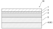
- FIG. 1 is a schematic diagram showing an example of a cross-sectional structure of an exterior material for an electricity storage device of the present disclosure
- BRIEF DESCRIPTION OF THE DRAWINGS FIG. 1 is a schematic diagram showing an example of a cross-sectional structure of an exterior material for an electricity storage device of the present disclosure
- BRIEF DESCRIPTION OF THE DRAWINGS FIG. 1 is a schematic diagram showing an example of a cross-sectional structure of an exterior material for an electricity storage device of the present disclosure
- BRIEF DESCRIPTION OF THE DRAWINGS FIG. 1 is a schematic diagram showing an example of a cross-sectional structure of an exterior material for an electricity storage device of the present disclosure
- BRIEF DESCRIPTION OF THE DRAWINGS FIG.
- FIG. 1 is a schematic diagram showing an example of a cross-sectional structure of an exterior material for an electricity storage device of the present disclosure
- FIG. 1 is a schematic diagram showing an example of a cross-sectional structure of an exterior material for an electricity storage device of the present disclosure
- It is a schematic diagram for demonstrating the corrosion-resistant evaluation method in an Example.
- FIG. 3 is a schematic diagram showing crystal grains and second phase particles in a cross section in the thickness direction of an aluminum alloy foil. This is a microscope image of the surface of an aluminum alloy foil observed after corrosion resistance evaluation, showing an example in which corrosion is suitably suppressed.
- FIG. 4 is a schematic diagram for explaining a method of measuring logarithmic decrement ⁇ E by rigid pendulum measurement;
- FIG. 4 is a schematic diagram for explaining a projecting portion formed inside a heat-sealed portion of a heat-sealable resin layer;
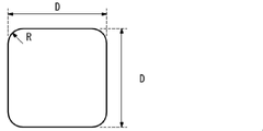
- FIG. 4 is a diagram showing a planar shape of a square punch used in a limit forming height test in an example of the present disclosure;
- the exterior material for an electricity storage device of the present disclosure is composed of a laminate including at least a substrate layer, a barrier layer, and a heat-fusible resin layer in this order, and the barrier layer contains Fe: 0.2% by mass. 2.0% by mass or less, Mg: 0.1% by mass or more and 5.0% by mass or less.
- the first heat-fusible resin layer constituting the surface of the laminate has a logarithmic attenuation rate ⁇ E at 140 ° C. in rigid pendulum measurement of 0.25 or less.
- the power storage device exterior material of the present disclosure by having the above configuration, it is excellent in moldability and effectively prevents corrosion of the aluminum alloy foil when electricity is applied in a state where the electrolytic solution is adhered. It is suppressed, and the insulation is also enhanced.
- the exterior material for an electricity storage device, the manufacturing method thereof, and the electricity storage device of the present disclosure will be described in detail below.
- the numerical range indicated by “-” means “more than” and “less than”.
- the notation of 2 to 15 mm means 2 mm or more and 15 mm or less.
- the exterior material 10 for an electricity storage device of the present disclosure is, for example, as shown in FIGS. consists of
- the base material layer 1 is the outermost layer
- the heat-fusible resin layer 4 is the innermost layer.
- the heat-sealable resin layers 4 of the electricity storage device exterior material 10 face each other, and the peripheral edges are heat-sealed.
- the electricity storage device element is accommodated in the space formed by .
- the barrier layer 3 is the reference
- the heat-fusible resin layer 4 side is inner than the barrier layer 3
- the base layer 1 side is more than the barrier layer 3. outside.
- the heat-fusible resin layer 4 is composed of a single layer or multiple layers. constitutes the surface of the laminate. 1 and 2, the heat-fusible resin layer 4 is composed of a single layer of the first heat-fusible resin layer 41, and the first heat-fusible resin layer 41 covers the surface of the laminate.
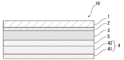
- Figure 3 illustrates the composing laminate structure. 3 to 5, the heat-fusible resin layer 4 is composed of multiple layers (two layers) of a first heat-fusible resin layer 41 and a second heat-fusible resin layer 42, The first heat-fusible resin layer 41 illustrates a laminated structure forming the surface of the laminated body.
- the heat-fusible resin layer 4 further includes a third heat-fusible resin layer, a fourth Another heat-fusible resin layer such as a heat-fusible resin layer may be provided on the barrier layer 3 side of the second heat-fusible resin layer 42 .
- the peripheral edges are heat-sealed while the first heat-fusible resin layers 41 of the electricity storage device exterior material 10 face each other.
- a power storage device element is housed in the space formed by the pressing.
- the barrier layer 3 of the power storage device exterior material of the present disclosure contains an aluminum alloy foil. That is, the barrier layer 3 of the power storage device exterior material of the present disclosure can be made of an aluminum alloy foil.
- the exterior material for an electricity storage device of the present disclosure which uses an aluminum alloy foil that satisfies a predetermined composition to be described later, has excellent moldability and effectively suppresses corrosion of the aluminum alloy foil.
- the logarithmic decrement ⁇ E at 140° C. is 0.25 or less, so that the first heat-fusible resin layer 41 is not crushed when heat-sealed. It is effectively suppressed, and the synergistic effect with the barrier layer (aluminum alloy foil) can improve the insulating properties of the exterior material for an electricity storage device.
- the electrical storage device exterior material 10 is provided between the base material layer 1 and the barrier layer 3 for the purpose of improving the adhesion between these layers, if necessary. It may have an adhesive layer 2 .
- the barrier layer 3 and the heat-fusible resin layer 4 for the purpose of improving the adhesion between these layers, if necessary, It may have an adhesive layer 5 .
- a surface coating layer 6 or the like may be provided on the outside of the base material layer 1 (the side opposite to the heat-fusible resin layer 4 side), if necessary.
- the thickness of the laminate that constitutes the power storage device exterior material 10 is not particularly limited, but from the viewpoint of cost reduction, energy density improvement, etc., it is, for example, 190 ⁇ m or less, preferably about 180 ⁇ m or less, about 155 ⁇ m or less, or about 120 ⁇ m or less. is mentioned.
- the thickness of the laminate constituting the power storage device exterior material 10 is preferably about 35 ⁇ m or more, about 45 ⁇ m or more, about 60 ⁇ m or more can be mentioned.
- the preferred range of the laminate constituting the power storage device exterior material 10 is, for example, about 35 to 190 ⁇ m, about 35 to 180 ⁇ m, about 35 to 155 ⁇ m, about 35 to 120 ⁇ m, about 45 to 190 ⁇ m, and about 45 to 180 ⁇ m. , about 45 to 155 ⁇ m, about 45 to 120 ⁇ m, about 60 to 190 ⁇ m, about 60 to 180 ⁇ m, about 60 to 155 ⁇ m, and about 60 to 120 ⁇ m, and particularly preferably about 60 to 155 ⁇ m.
- the thickness (total thickness) of the laminate constituting the power storage device exterior material 10 is the base layer 1, the adhesive layer 2 provided as necessary, the barrier layer 3, if necessary
- the ratio of the total thickness of the adhesive layer 5, the heat-fusible resin layer 4, and the surface coating layer 6 provided as necessary is preferably 90% or more, more preferably 95% or more, More preferably, it is 98% or more.
- the electrical storage device exterior material 10 of the present disclosure includes the base material layer 1, the adhesive layer 2, the barrier layer 3, the adhesive layer 5, and the heat-fusible resin layer 4, the electrical storage device exterior
- the ratio of the total thickness of each layer to the thickness (total thickness) of the laminate constituting the material 10 is preferably 90% or more, more preferably 95% or more, and still more preferably 98% or more.
- the power storage device exterior material 10 of the present disclosure is a laminate including the base material layer 1, the adhesive layer 2, the barrier layer 3, and the heat-fusible resin layer 4, the power storage device exterior material
- the ratio of the total thickness of each of these layers to the thickness (total thickness) of the laminate constituting 10 is, for example, 80% or more, preferably 90% or more, more preferably 95% or more, and further preferably 98% or more. can be done.
- the barrier layer 3 described later can usually be distinguished between MD (Machine Direction) and TD (Transverse Direction) in the manufacturing process.
- MD Machine Direction
- TD Transverse Direction
- the barrier layer 3 is made of an aluminum alloy foil
- linear streaks called rolling marks are formed on the surface of the metal foil in the rolling direction (RD) of the metal foil. Since the rolling marks extend along the rolling direction, the rolling direction of the metal foil can be grasped by observing the surface of the metal foil.
- the MD of the laminate usually matches the RD of the metal foil, so the surface of the metal foil of the laminate is observed to identify the rolling direction (RD) of the metal foil.
- the MD of the laminate can be specified.
- the TD of the laminate is perpendicular to the MD of the laminate, the TD of the laminate can also be specified.
- the MD of the electrical storage device exterior material cannot be specified due to the rolling marks of the aluminum alloy foil, it can be specified by the following method.
- a method for confirming the MD of the exterior material for an electricity storage device there is a method for confirming the sea-island structure by observing the cross section of the heat-fusible resin layer of the exterior material for the electricity storage device with an electron microscope.
- the MD can be determined as the direction parallel to the cross section in which the average diameter of the island shape in the direction perpendicular to the thickness direction of the heat-fusible resin layer is maximum.
- the cross section in the length direction of the heat-fusible resin layer is changed by 10 degrees from a direction parallel to the cross section in the length direction, and the direction is perpendicular to the cross section in the length direction. (10 cross sections in total) are observed with electron micrographs to confirm the sea-island structure.
- the shape of each individual island is observed.
- the linear distance connecting the leftmost end in the direction perpendicular to the thickness direction of the heat-sealable resin layer and the rightmost end in the perpendicular direction is defined as the diameter y.
- the average of the top 20 diameters y of the island shape is calculated in descending order of diameter y.
- the direction parallel to the cross section in which the average diameter y of the island shape is the largest is determined as the MD.
- the base material layer 1 is a layer provided for the purpose of exhibiting a function as a base material of an exterior material for an electric storage device.
- the base material layer 1 is located on the outer layer side of the exterior material for electrical storage devices.
- the material forming the base material layer 1 is not particularly limited as long as it functions as a base material, that is, at least has insulating properties.
- the base material layer 1 can be formed using, for example, a resin, and the resin may contain additives described later.
- the substrate layer 1 may be, for example, a resin film made of resin, or may be formed by applying resin.
- the resin film may be an unstretched film or a stretched film.
- stretched films include uniaxially stretched films and biaxially stretched films, with biaxially stretched films being preferred.
- stretching methods for forming a biaxially stretched film include successive biaxial stretching, inflation, and simultaneous biaxial stretching.
- Methods for applying the resin include a roll coating method, a gravure coating method, an extrusion coating method, and the like.
- resins forming the base material layer 1 include resins such as polyester, polyamide, polyolefin, epoxy resin, acrylic resin, fluororesin, polyurethane, silicon resin, phenolic resin, and modified products of these resins. Further, the resin forming the base material layer 1 may be a copolymer of these resins or a modified product of the copolymer. Furthermore, it may be a mixture of these resins.
- polyesters and polyamides are preferred as resins forming the base material layer 1 .
- polyester examples include polyethylene terephthalate, polybutylene terephthalate, polyethylene naphthalate, polybutylene naphthalate, polyethylene isophthalate, and copolymerized polyester.
- copolyester examples include copolyester having ethylene terephthalate as a main repeating unit.
- copolymer polyester polymerized with ethylene isophthalate with ethylene terephthalate as the main repeating unit hereinafter abbreviated after polyethylene (terephthalate / isophthalate)
- polyethylene (terephthalate / adipate) polyethylene (terephthalate / sodium sulfoisophthalate)
- polyethylene (terephthalate/sodium isophthalate) polyethylene (terephthalate/phenyl-dicarboxylate), polyethylene (terephthalate/decanedicarboxylate), and the like.
- These polyesters may be used singly or in combination of two or more.
- polyamide specifically, aliphatic polyamide such as nylon 6, nylon 66, nylon 610, nylon 12, nylon 46, copolymer of nylon 6 and nylon 66; terephthalic acid and / or isophthalic acid Hexamethylenediamine-isophthalic acid-terephthalic acid copolymer polyamide such as nylon 6I, nylon 6T, nylon 6IT, nylon 6I6T (I represents isophthalic acid, T represents terephthalic acid) containing structural units derived from, polyamide MXD6 (polymetallic Polyamides containing aromatics such as silylene adipamide); alicyclic polyamides such as polyamide PACM6 (polybis(4-aminocyclohexyl)methane adipamide); Copolymerized polyamides, polyesteramide copolymers and polyetheresteramide copolymers which are copolymers of copolymerized polyamides with polyesters or polyalkylene ether glycols; and polyamides such
- the substrate layer 1 preferably includes at least one of a polyester film, a polyamide film, and a polyolefin film, preferably includes at least one of a stretched polyester film, a stretched polyamide film, and a stretched polyolefin film, More preferably, at least one of an oriented polyethylene terephthalate film, an oriented polybutylene terephthalate film, an oriented nylon film, and an oriented polypropylene film is included, and the biaxially oriented polyethylene terephthalate film, biaxially oriented polybutylene terephthalate film, and biaxially oriented nylon film , biaxially oriented polypropylene film.
- the base material layer 1 may be a single layer, or may be composed of two or more layers.
- the substrate layer 1 may be a laminate obtained by laminating resin films with an adhesive or the like, or may be formed by co-extrusion of resin to form two or more layers. It may also be a laminate of resin films. A laminate of two or more resin films formed by coextrusion of resin may be used as the base material layer 1 without being stretched, or may be used as the base material layer 1 by being uniaxially or biaxially stretched.
- the laminate of two or more resin films in the substrate layer 1 include a laminate of a polyester film and a nylon film, a laminate of nylon films of two or more layers, and a laminate of polyester films of two or more layers. etc., preferably a laminate of a stretched nylon film and a stretched polyester film, a laminate of two or more layers of stretched nylon films, and a laminate of two or more layers of stretched polyester films.
- the substrate layer 1 is a laminate of two layers of resin films, a laminate of polyester resin films and polyester resin films, a laminate of polyamide resin films and polyamide resin films, or a laminate of polyester resin films and polyamide resin films.
- a laminate is preferred, and a laminate of polyethylene terephthalate film and polyethylene terephthalate film, a laminate of nylon film and nylon film, or a laminate of polyethylene terephthalate film and nylon film is more preferred.
- the polyester resin is resistant to discoloration when, for example, an electrolytic solution adheres to the surface. It is preferably located in the outermost layer.
- the two or more layers of resin films may be laminated via an adhesive.
- Preferred adhesives are the same as those exemplified for the adhesive layer 2 described later.
- the method for laminating two or more layers of resin films is not particularly limited, and known methods can be employed. Examples thereof include dry lamination, sandwich lamination, extrusion lamination, thermal lamination, and the like. A lamination method is mentioned.
- the thickness of the adhesive is, for example, about 2 to 5 ⁇ m.
- an anchor coat layer may be formed on the resin film and laminated.
- the anchor coat layer the same adhesives as those exemplified in the adhesive layer 2 described later can be used. At this time, the thickness of the anchor coat layer is, for example, about 0.01 to 1.0 ⁇ m.
- At least one of the surface and the inside of the substrate layer 1 may contain additives such as lubricants, flame retardants, antiblocking agents, antioxidants, light stabilizers, tackifiers, and antistatic agents. good. Only one type of additive may be used, or two or more types may be mixed and used.
- a lubricant exists on the surface of the base material layer 1 from the viewpoint of improving the moldability of the exterior material for an electricity storage device.
- the lubricant is not particularly limited, but preferably includes an amide-based lubricant.
- Specific examples of amide lubricants include saturated fatty acid amides, unsaturated fatty acid amides, substituted amides, methylolamides, saturated fatty acid bisamides, unsaturated fatty acid bisamides, fatty acid ester amides, and aromatic bisamides.
- saturated fatty acid amides include lauric acid amide, palmitic acid amide, stearic acid amide, behenic acid amide, and hydroxystearic acid amide.
- unsaturated fatty acid amides include oleic acid amide and erucic acid amide.
- substituted amides include N-oleyl palmitic acid amide, N-stearyl stearic acid amide, N-stearyl oleic acid amide, N-oleyl stearic acid amide, N-stearyl erucic acid amide and the like.
- methylolamide include methylol stearamide.
- saturated fatty acid bisamides include methylenebisstearic acid amide, ethylenebiscapric acid amide, ethylenebislauric acid amide, ethylenebisstearic acid amide, ethylenebishydroxystearic acid amide, ethylenebisbehenic acid amide, hexamethylenebisstearin. acid amide, hexamethylenebisbehenamide, hexamethylenehydroxystearic acid amide, N,N'-distearyladipic acid amide, N,N'-distearylsebacic acid amide and the like.
- unsaturated fatty acid bisamides include ethylenebisoleic acid amide, ethylenebiserucic acid amide, hexamethylenebisoleic acid amide, N,N'-dioleyladipic acid amide, and N,N'-dioleylsebacic acid amide. etc.
- fatty acid ester amides include stearamide ethyl stearate.
- aromatic bisamide include m-xylylenebisstearic acid amide, m-xylylenebishydroxystearic acid amide, N,N'-distearyl isophthalic acid amide and the like.
- Lubricants may be used singly or in combination of two or more.
- a lubricant exists on the surface of the base material layer 1, its amount is not particularly limited, but is preferably about 3 mg/m 2 or more, more preferably about 4 to 15 mg/m 2 , and still more preferably 5 to 14 mg. / m 2 degree.
- the lubricant present on the surface of the substrate layer 1 may be obtained by exuding the lubricant contained in the resin constituting the substrate layer 1, or by coating the surface of the substrate layer 1 with the lubricant.
- the thickness of the base material layer 1 is not particularly limited as long as it functions as a base material, but it is, for example, about 3 to 50 ⁇ m, preferably about 10 to 35 ⁇ m.
- the thickness of each resin film constituting each layer is preferably about 2 to 25 ⁇ m.
- the adhesive layer 2 is a layer provided between the base layer 1 and the barrier layer 3 as necessary for the purpose of enhancing the adhesiveness between them.
- the adhesive layer 2 is made of an adhesive that can bond the base material layer 1 and the barrier layer 3 together.
- the adhesive used to form the adhesive layer 2 is not limited, but may be any of a chemical reaction type, a solvent volatilization type, a hot melt type, a hot pressure type, and the like. Further, it may be a two-liquid curing adhesive (two-liquid adhesive), a one-liquid curing adhesive (one-liquid adhesive), or a resin that does not involve a curing reaction. Further, the adhesive layer 2 may be a single layer or multiple layers.
- the adhesive component contained in the adhesive include polyesters such as polyethylene terephthalate, polybutylene terephthalate, polyethylene naphthalate, polybutylene naphthalate, polyethylene isophthalate, and copolymerized polyester; polyether; polyurethane; epoxy resin; Phenolic resins; polyamides such as nylon 6, nylon 66, nylon 12, and copolymerized polyamides; polyolefin resins such as polyolefins, cyclic polyolefins, acid-modified polyolefins, and acid-modified cyclic polyolefins; polyvinyl acetate; cellulose; (meth)acrylic resins; polyimide; polycarbonate; amino resin such as urea resin and melamine resin; rubber such as chloroprene rubber, nitrile rubber and styrene-butadiene rubber; These adhesive components may be used singly or in combination of two or more.
- polyurethane adhesives are preferred.
- an appropriate curing agent can be used in combination with these adhesive component resins to increase the adhesive strength.
- the curing agent is selected from among polyisocyanates, polyfunctional epoxy resins, oxazoline group-containing polymers, polyamine resins, acid anhydrides, etc., depending on the functional groups of the adhesive component.
- polyurethane adhesives examples include polyurethane adhesives containing a main agent containing a polyol compound and a curing agent containing an isocyanate compound.
- Two-component curing type polyurethane adhesives using polyols such as polyester polyols, polyether polyols, and acrylic polyols as main agents and aromatic or aliphatic polyisocyanates as curing agents are preferred.
- the polyol compound it is preferable to use a polyester polyol having a hydroxyl group in a side chain in addition to the terminal hydroxyl group of the repeating unit.
- the adhesive layer 2 is formed of a polyurethane adhesive, the exterior material for an electric storage device is imparted with excellent electrolyte resistance, and even if the electrolyte adheres to the side surface, the base layer 1 is suppressed from being peeled off. .
- the adhesive layer 2 may contain other components as long as they do not impede adhesion, and may contain colorants, thermoplastic elastomers, tackifiers, fillers, and the like. Since the adhesive layer 2 contains a coloring agent, the exterior material for an electric storage device can be colored. Known substances such as pigments and dyes can be used as the colorant. In addition, only one type of colorant may be used, or two or more types may be mixed and used.
- the type of pigment is not particularly limited as long as it does not impair the adhesiveness of the adhesive layer 2.
- organic pigments include azo-based, phthalocyanine-based, quinacridone-based, anthraquinone-based, dioxazine-based, indigothioindigo-based, perinone-perylene-based, isoindolenine-based, and benzimidazolone-based pigments.
- pigments include carbon black, titanium oxide, cadmium, lead, chromium oxide, and iron pigments, as well as fine powder of mica and fish scale foil.
- carbon black is preferable, for example, in order to make the external appearance of the exterior material for a power storage device black.
- the average particle size of the pigment is not particularly limited, and is, for example, about 0.05 to 5 ⁇ m, preferably about 0.08 to 2 ⁇ m.
- the average particle size of the pigment is the median size measured with a laser diffraction/scattering particle size distribution analyzer.
- the content of the pigment in the adhesive layer 2 is not particularly limited as long as the power storage device exterior material is colored, and is, for example, about 5 to 60% by mass, preferably 10 to 40% by mass.
- the thickness of the adhesive layer 2 is not particularly limited as long as the substrate layer 1 and the barrier layer 3 can be adhered. , about 5 ⁇ m or less, and preferable ranges include about 1 to 10 ⁇ m, about 1 to 5 ⁇ m, about 2 to 10 ⁇ m, and about 2 to 5 ⁇ m.
- the colored layer is a layer provided as necessary between the base layer 1 and the barrier layer 3 (not shown).
- a colored layer may be provided between the base material layer 1 and the adhesive layer 2 and between the adhesive layer 2 and the barrier layer 3 . Further, a colored layer may be provided outside the base material layer 1 . By providing the colored layer, the exterior material for an electricity storage device can be colored.
- the colored layer can be formed, for example, by applying ink containing a coloring agent to the surface of the base material layer 1, the surface of the adhesive layer 2, or the surface of the barrier layer 3.
- ink containing a coloring agent such as pigments and dyes can be used as the colorant.
- pigments and dyes can be used as the colorant.
- only one type of colorant may be used, or two or more types may be mixed and used.
- colorant contained in the colored layer are the same as those exemplified in the [Adhesive layer 2] column.
- the barrier layer 3 is a layer that at least prevents permeation of moisture.
- the barrier layer 3 of the power storage device exterior material of the present disclosure contains an aluminum alloy foil.
- the aluminum alloy foil includes an aluminum alloy foil that satisfies the following composition: Fe (iron): 0.2 mass % or more and 2.0 mass % or less; Mg (magnesium): 0.1 mass % or more and 5.0 mass % or less.
- the main component of the aluminum alloy foil is Al (aluminum), and for example, 92.10% by mass or more is composed of aluminum.
- the aluminum alloy foil preferably contains Si (silicon). The silicon content is preferably less than or equal to about 0.50% by weight.
- the aluminum alloy foil may contain components other than Fe, Mg, and Al.
- Other components include, for example, inevitable impurities such as Si (silicon), Mn (manganese), Cu (copper), Cr (chromium), and Zn (zinc).
- the inevitable impurities in the aluminum alloy foil are, for example, 0.10% by mass or less individually and 0.40% by mass or less in total.
- the other component may be of one type or two or more types.
- the Fe content is below the lower limit (0.2% by mass)
- the distribution density of coarse intermetallic compounds is low
- the effect of grain refinement is low
- the final grain size distribution becomes uneven.
- the Fe content exceeds the upper limit (2.0% by mass)
- the grain refining effect is saturated or rather reduced, and the size of the Al—Fe intermetallic compound produced during casting becomes very large. , the elongation and rollability of the aluminum alloy foil are reduced.
- the content of Fe is set to the above range of 0.2% by mass or more and 2.0% by mass or less.
- the lower limit of the Fe content is preferably 0.5% by mass, and for the same reason, the lower limit of the Fe content is preferably 1.0% by mass and the upper limit is 1.8% by mass. .
- Mg dissolves in aluminum and can increase the strength of the aluminum alloy foil through solid-solution strengthening.
- Mg easily dissolves in aluminum, even if it is contained together with Fe, there is little risk of coarsening of intermetallic compounds and deterioration of formability and rollability.
- the Mg content is less than the lower limit (0.1% by mass)
- the improvement in strength is insufficient
- the upper limit 5.0% by mass
- the aluminum alloy foil becomes hard, resulting in a decrease in rollability and formability. invite.
- a particularly preferred lower limit is 0.5% by mass.
- the Mg content exceeds 5.0% by mass, the aluminum alloy foil becomes hard and the formability and rollability deteriorate, but it is possible to obtain an aluminum alloy foil having a very high strength. It is desirable that the content of Mg is in the range of more than 0.5% by mass and 4.5% by mass or less. In addition, the addition of Mg improves the corrosion resistance of the exterior material for an electric storage device to the electrolytic solution. Although the details of the mechanism are not clear, the larger the amount of Mg added, the more difficult it is for the aluminum alloy foil to react with lithium or the like in the electrolytic solution, which can suppress the pulverization of the aluminum alloy foil and the formation of through holes.
- Si may be added for the purpose of increasing the strength of the aluminum alloy foil if it is a trace amount, but in the present disclosure, by making it 0.5% by mass or less, the Al generated during casting - The size of the Fe--Si intermetallic compound is reduced, and the elongation and formability of the aluminum alloy foil are enhanced. Therefore, even when the thickness of the aluminum alloy foil is thin, fracture originating from the intermetallic compound is less likely to occur, and the rollability is improved. In addition, by not adding a large amount of Si to an alloy with a high Mg content, the amount of Mg—Si precipitates formed is reduced, and it is difficult to reduce the rollability and the amount of Mg in solid solution, resulting in a decrease in strength. become difficult.
- the Si content it is desirable to suppress the Si content to 0.2% by mass or less.
- the lower limit of the Si content is desirably 0.001% by mass, more desirably 0.005% by mass. It should be noted that the lower the Si content, the better the formability, rollability, grain refinement degree, and ductility.
- the aluminum alloy foil can contain unavoidable impurities such as Cu and Mn. It is desirable that the content of these impurities is, for example, 0.1% by mass or less. In addition, as the present disclosure, the upper limit of the content of the inevitable impurities is not limited to the above numerical value.
- Mn is difficult to form a solid solution in aluminum, unlike Mg, it cannot be expected to significantly increase the strength of the aluminum alloy foil by solid solution strengthening. Also, if a large amount of Mn is added to an alloy with a high Fe content, there is a high risk of coarsening of intermetallic compounds and formation of Al-Fe-Mn-based giant intermetallic compounds, resulting in deterioration of rollability and formability. There is fear.
- the Mn content is desirably 0.1% by mass or less.
- the Mn content is more desirably 0.08% by mass or less.
- the lower limit of the Mn content is desirably 0.001% by mass, more desirably 0.005% by mass.
- Mn manganese : It is preferable to satisfy a composition of 0.1% by mass or less, more preferably to satisfy a composition of Mn: 0.01% by mass or more and 0.1% by mass or less, Mn: 0.01% by mass or more and 0.08 It is more preferable to satisfy the composition of mass % or less.
- ⁇ Fe 0.2% by mass or more and 2.0% by mass or less Fe crystallizes as an Al-Fe intermetallic compound during casting, and if the size of the compound is large, it becomes a recrystallization site during annealing. It has the effect of refining crystal grains.
- the content of Fe is set within the above range.
- the lower limit of the Fe content is preferably 0.5% by mass, and for the same reason, the lower limit of the Fe content is preferably 1.0% by mass and the upper limit is 1.8% by mass. .
- Mg dissolves in aluminum and can increase the strength of the soft foil by solid-solution strengthening.
- Mg since Mg is easily dissolved in aluminum, even if it is contained together with Fe, there is little risk of coarsening of intermetallic compounds and deterioration of formability and rollability. If the Mg content is below the lower limit, the strength will not be sufficiently improved, and if the Mg content is above the upper limit, the aluminum alloy foil will become hard, resulting in reduced rollability and formability.
- a particularly preferable range for the Mg content is 0.5% by mass or more and 5.0% by mass or less. It was also confirmed that the addition of Mg improves the corrosion resistance of the lithium ion secondary battery to the electrolytic solution.
- the lower limit of the Mg content is desirably 0.5% by mass, even if a particularly clear improvement in corrosion resistance is expected, although formability is slightly reduced.
- Si 0.5% by mass or less
- Si may be added for the purpose of increasing the strength of the foil if it is a trace amount, but in the present disclosure, the Si content is 0.5% or less .
- the size of the Al-Fe-Si intermetallic compound generated during casting is reduced, the elongation and formability of the foil are enhanced, and even when the foil thickness is thin, breakage starting from the intermetallic compound is less likely to occur.
- the content is preferably 0.5% by mass or less because the rollability is also improved.
- the amount of Mg—Si based precipitates produced is reduced, making it difficult for deterioration of rollability and the amount of Mg in solid solution to occur, and strength to decrease.
- unavoidable impurities such as Cu and Mn can be included.
- the amount of each element of these unavoidable impurities is desirably 0.1% by mass or less.
- the upper limit of the content of the inevitable impurities is not limited to the above numerical value.
- Mn is difficult to form a solid solution in aluminum, unlike Mg, it cannot be expected to greatly increase the strength of the soft foil by solid-solution strengthening.
- the Mn content is desirably 0.1% by mass or less.
- each orientation density of the copper orientation and R orientation of the texture is 15 or less
- the texture has a great influence on the mechanical properties and formability of the foil.
- the surface Mg concentration is 5.0 atomic percent or more and the oxide film thickness is 80 ⁇ or more (Mg: 0.1% by mass or more and 1.5% by mass or less)
- Mg 0.1% by mass or more and 1.5% by mass or less
- the details of the mechanism are not clear, it has been confirmed that the Mg concentration on the foil surface and the thickness of the oxide film contribute to the corrosion resistance of the lithium ion secondary battery to the electrolyte. Corrosion resistance is improved due to the high Mg concentration on the foil surface and the formation of a thick oxide film. Therefore, when Mg is 0.1% by mass or more and 1.5% by mass or less, it is desirable to set the Mg concentration on the aluminum foil surface to 5.0 atomic percent or more and the oxide film thickness to be 80 ⁇ or more.
- the surface Mg concentration is 15.0 atomic percent or more and the oxide film thickness is 200 ⁇ or more. More desirably, the surface Mg concentration is 20.0 atomic percent or more.
- the surface Mg concentration is the Mg concentration in the surface portion from the outermost surface to a depth of 8 nm, and the Mg concentration is the amount with respect to the total of 100 atomic % of all elements.
- the surface Mg concentration is 15.0 atomic percent or more and the oxide film thickness is 120 ⁇ or more (when Mg: more than 1.5% by mass and 5.0% by mass or less)
- the Mg concentration on the foil surface and the thickness of the oxide film contribute to the corrosion resistance of the lithium ion secondary battery to the electrolytic solution. Corrosion resistance is improved due to the high Mg concentration on the foil surface and the formation of a thick oxide film. Therefore, when the Mg content is more than 1.5% by mass and 5.0% by mass or less, it is desirable to set the Mg concentration on the aluminum foil surface to 15.0 atomic percent or more and the oxide film thickness to be 120 ⁇ or more. More preferably, the surface Mg concentration is 20.0 atomic percent or more and the oxide film thickness is 220 ⁇ or more. More desirably, the surface Mg concentration is 25.0 atomic percent or more.
- L1 is the length of the large-angle grain boundary per unit area
- L2 is the length of the small-angle grain boundary measured by the backscattered electron diffraction method.
- the proportion of high-angle grain boundaries (HAGB) and low-angle grain boundaries (LAGB) in the recrystallized grain structure after annealing affects the elongation and formability of the foil.
- HAGB high-angle grain boundaries
- LAGB low-angle grain boundaries
- ⁇ Tensile strength 110 MPa or more and 180 MPa or less (when Mg: 0.1 mass% or more and 1.5 mass% or less) Mg: When it is 0.1% by mass or more and 1.5% by mass or less, a tensile strength of 110 MPa or more is required to dramatically improve the impact resistance and puncture strength of existing foils such as JIS A8079 and 8021. is required. It is preferable that the tensile strength be 180 MPa or less. Tensile strength can be achieved by selection of composition and optimization of grain size.
- Tensile strength 180 MPa or more (when Mg: more than 1.5% by mass and 5.0% by mass or less) Mg: When more than 1.5% by mass and 5.0% by mass or less, a tensile strength of 180 MPa or more is required to dramatically improve the impact resistance and puncture strength of existing foils such as JIS A8079 and 8021. is preferred. For the same reason, the tensile strength is desirably 200 MPa or more. However, the higher the tensile strength, the lower the moldability. Therefore, when the moldability is emphasized, it is better to suppress the tensile strength. As noted above, tensile strength can be achieved through composition selection and grain size optimization.
- ⁇ Average crystal grain size 25 ⁇ m or less
- the average grain size is desirably 25 ⁇ m or less in order to achieve high elongation properties and accompanying high formability.
- the average grain size can be achieved by selecting the composition and manufacturing conditions that optimize the homogenization treatment and cold rolling rate.
- a preferred composition of the aluminum alloy foil includes, for example, those satisfying the compositions of Specific Examples 1 and 2 below.
- Si 0.1% by mass or more and 0.5% by mass or less Fe: 0.2% by mass or more and 2.0% by mass or less Mg: 0.1% by mass or more and 5.0% by mass or less Mn: 0.1 % by mass, Cu: 0.0% by mass, Cr: 0.0% by mass, Zr: 0.0% by mass, and other unavoidable impurities are 0.05% by mass or less individually and 0.15% by mass in total. % or less, and the balance is more preferably Al.
- the aluminum alloy foil contains Si: 0.5% by mass or less, Fe: 0.2% by mass or more and 2.0% by mass or less, Mg: 0.1% by mass or more and 5.0% by mass or less, Mn: 0.5% by mass or less. 1% by mass, Cu: 0.0% by mass, Cr: 0.0% by mass, Zr: 0.0% by mass, and other inevitable impurities are 0.05% by mass or less individually and 0.15% in total % by mass or less, and the balance is Al.
- the tensile strength of the aluminum alloy foil is 100 MPa or more, and 200 MPa or more. is more desirable.
- the upper limit of tensile strength is desirably 350 MPa.
- the tensile strength is desirably 200 MPa or more and 350 MPa or less, and more desirably 200 MPa or more and 310 MPa or less.
- the higher the tensile strength the lower the moldability. Therefore, when the moldability is important, it is better to suppress the tensile strength.
- the aluminum alloy foil has a tensile strength of 100 MPa or more and 180 MPa or less, measured on a JIS No. 5 test piece in accordance with JIS Z2241:2011. is preferred. Specifically, the tensile strength is measured by the method described in Examples. The tensile strength of aluminum alloy foil can be achieved by selecting the composition and optimizing the grain size.
- the effect of elongation on the formability of aluminum alloy foil varies greatly depending on the forming method, and elongation alone does not determine formability.
- the aluminum alloy foil preferably has an elongation at break of 10% or more, more preferably 15% or more, as measured on a JIS No. 5 test piece in accordance with JIS Z2241:2011.
- the upper limit of breaking elongation is desirably 40%, more desirably 30%.
- the elongation at break is desirably 0% to 40%, more desirably 15% to 40%, and even more desirably 15% to 30%.
- the elongation at break is measured by the method described in Examples.
- the elongation properties of the aluminum alloy foil can be achieved by selecting the composition and refining the grain size.
- the aluminum alloy foil that satisfies the composition and properties as described above can be obtained, for example, by adjusting the composition based on an aluminum alloy having a composition in the alloy number A5000 series of JIS H4000:2014, and using a known method for producing an aluminum alloy foil, for example: , melting, homogenization, hot rolling, cold rolling, intermediate annealing, cold rolling, and final annealing.
- a known method for producing an aluminum alloy foil for example: , melting, homogenization, hot rolling, cold rolling, intermediate annealing, cold rolling, and final annealing.
- the description in Japanese Patent Application Laid-Open No. 2005-163077 can be referred to.
- the analysis of each chemical component contained in the aluminum alloy foil is performed by the analytical test specified in JIS H4160-1994.
- an aluminum alloy ingot satisfying the composition of Fe: 0.2% by mass to 2.0% by mass and Mg: 0.1% by mass to 5.0% by mass is cast by a conventional method such as semi-continuous casting. Cast by The obtained ingot is homogenized at 480-540° C. for 6-12 hours.
- the homogenization treatment of aluminum materials is performed at 400 to 600 ° C. for a long time (for example, about 12 hours), but considering grain refinement by adding Fe as in the present disclosure, heat treatment at 480 to 540 ° C. for 6 hours or more. It is desirable to If the temperature is less than 480°C, grain refinement is insufficient, and if it exceeds 540°C, the grains become coarse. If the treatment time is less than 6 hours, homogenization will be insufficient.
- Hot rolling is performed to obtain an aluminum alloy plate with the desired thickness.
- Hot rolling can be performed by a conventional method, and the coiling temperature for hot rolling is desirably higher than the recrystallization temperature, specifically 300° C. or higher.
- the recrystallization temperature specifically 300° C. or higher.
- fine Al-Fe intermetallic compounds of 0.3 ⁇ m or less are precipitated, and recrystallized grains and fiber grains coexist after hot rolling, resulting in non-uniform crystal grain sizes after intermediate annealing and final annealing. It is not desirable because there is a concern that the elongation characteristics will deteriorate.
- the aluminum alloy foil of the present disclosure After hot rolling, cold rolling, intermediate annealing, and final cold rolling are performed to obtain the aluminum alloy foil of the present disclosure by making the thickness 5 to 100 ⁇ m. It is desirable that the final cold rolling reduction be 90% or more.
- intermediate annealing may not be performed during cold rolling, it may be performed in some cases.
- intermediate annealing There are two types of intermediate annealing: batch annealing, in which the coil is placed in a furnace and held for a certain period of time, and rapid heating and cooling of the material in a continuous annealing line (hereinafter referred to as CAL annealing).
- batch annealing in which the coil is placed in a furnace and held for a certain period of time
- CAL annealing rapid heating and cooling of the material in a continuous annealing line
- any method may be used, but CAL annealing is desirable for grain refinement and high strength, and batch annealing is desirable for formability.
- heating rate 10 to 250° C./sec
- heating temperature 400° C. to 550° C.
- no holding time or holding time 5 seconds or less
- Cooling rate A condition of 20 to 200° C./sec
- the presence or absence of intermediate annealing, the conditions for performing intermediate annealing, and the like are not limited to specific ones.
- final annealing is performed to make a soft foil.
- Final annealing after foil rolling may generally be performed at 250°C to 400°C.
- the softening is insufficient, and there is a concern that the concentration of Mg on the foil surface will be insufficient and the corrosion resistance will decrease. If the temperature exceeds 400° C., Mg may be excessively concentrated on the foil surface, discoloring the foil, or the properties of the oxide film may change to cause minute cracks, resulting in deterioration of corrosion resistance. If the final annealing time is less than 5 hours, the effect of the final annealing is insufficient.
- An aluminum alloy ingot is cast by a conventional method such as a semi-continuous casting method.
- the aluminum alloy ingot contains Fe: 0.2% by mass or more and 2.0% by mass or less, Mg: 0.1% by mass or more and 5.0% by mass or less, and the balance contains Al and unavoidable impurities. It has a composition of Mn: 0.1% by mass or less.
- the obtained ingot is homogenized at 480-540° C. for 6-12 hours.
- Homogenization treatment 450 to 550 ° C
- the purpose of the homogenization treatment is to eliminate micro-segregation in the ingot and to adjust the distribution of intermetallic compounds, and is a very important treatment for finally obtaining the desired crystal grain structure.
- the homogenization treatment of aluminum materials is performed at 400 to 600° C. for a long time, but in the present invention, it is necessary to consider grain refinement by adding Fe.
- the temperature is less than 450° C., precipitation of Fe becomes insufficient, and there is concern about coarsening of crystal grains during the final annealing.
- the ratio of in-situ recrystallization increases, the ratio of LAGB increases, and there is concern about a decrease in L1/L2.
- crystallized substances grow remarkably, leading to coarsening of crystal grains and deterioration of formability during the final annealing. It is necessary to secure at least 3 hours or more for the homogenization treatment. If the time is less than 3 hours, precipitation is not sufficient and the density of the fine intermetallic compounds is lowered.
- the temperature is 480 to 520° C. and the time is 5 hours or more.
- Hot rolling is performed to obtain an aluminum alloy plate with the desired thickness.
- Hot rolling can be performed by a conventional method, and the coiling temperature for hot rolling is desirably higher than the recrystallization temperature, specifically 300° C. or higher. If the temperature is less than 300° C., fine Al—Fe intermetallic compounds of 0.3 ⁇ m or less are deposited.
- recrystallized grains and fiber grains coexist after hot rolling, and the crystal grain size after intermediate annealing and final annealing may become non-uniform, resulting in deterioration in elongation characteristics, which is not desirable.
- intermediate annealing After hot rolling, cold rolling, intermediate annealing, and final cold rolling are performed to obtain the aluminum alloy foil of the present invention with a thickness of 5 to 100 ⁇ m.
- intermediate annealing There are two types of intermediate annealing: batch annealing, in which coils are placed in a furnace and held for a certain period of time, and rapid heating and rapid cooling in a continuous annealing line (hereinafter referred to as CAL annealing). Any method may be used when the intermediate annealing is applied, but CAL annealing is preferable for refining the crystal grains and increasing the strength.
- batch annealing is preferable if formability is given priority.
- conditions of 300 to 400° C. for 3 hours or more can be adopted.
- CAL annealing the following conditions shall be adopted: heating rate: 10 to 250°C/sec, heating temperature: 400°C to 550°C, no holding time or holding time: 5 seconds or less, cooling rate: 20 to 200°C/sec. can be done.
- the presence or absence of intermediate annealing, the conditions for performing intermediate annealing, and the like are not limited to specific ones.
- Final cold rolling reduction 84.0% or more and 97.0% or less
- the more desirable final cold rolling reduction range is 90.0% or more and 93.0% or less.
- final annealing is performed to obtain a soft foil.
- Final annealing after foil rolling may generally be performed at 250°C to 400°C.
- the temperature is more preferably 350°C to 400°C. If the final annealing temperature is low, the softening is insufficient, and there is concern that the L1/L2 ratio will decrease and the densities of each orientation of the Copper orientation and the R orientation will increase.
- the concentration of Mg on the foil surface and the growth of the oxide film will be insufficient, resulting in a decrease in corrosion resistance.
- Mg may be excessively concentrated on the foil surface, discoloring the foil, or the properties of the oxide film may change to cause minute cracks, resulting in deterioration of corrosion resistance. If the final annealing time is less than 5 hours, the effect of the final annealing is insufficient.
- the obtained aluminum alloy foil has a tensile strength of 110 MPa or more and 180 MPa or less and a breaking elongation of 10% or more at room temperature when Mg: 0.1 mass% or more and 1.5 mass% or less.
- the tensile strength is 180 MPa or more and the elongation at break is 15% or more.
- the average crystal grain size is 25 ⁇ m or less. The average grain size can be determined by the cutting method specified in JIS G0551.
- the aluminum alloy foil has a thickness of, for example, about 85 ⁇ m or less, further about 50 ⁇ m or less, or even about 40 ⁇ m or less, which is a very thin aluminum alloy foil, the aluminum alloy foil is laminated on the exterior material for the power storage device, and formed. Pinholes and cracks are less likely to occur when pressed, and the exterior material for an electric storage device can be provided with excellent moldability.
- the average diameter y of the second phase particles 3b in the aluminum alloy foil (barrier layer 3) is 10.0 ⁇ m or less, so that the thickness of the aluminum alloy foil is, for example, about 85 ⁇ m or less, or even about It is 50 ⁇ m or less, further about 40 ⁇ m or less, and even if the total thickness of the exterior material for an electric storage device is as thin as the above, for example, pinholes and cracks are unlikely to occur during molding, and excellent moldability can be achieved. I have.
- the average diameter y is more preferably about 1.0 to 8.0 ⁇ m, more preferably about 1.0 to 6.0 ⁇ m. Since FIG. 7 is a schematic diagram, drawing is omitted, and 100 second phase particles 3b are not drawn.
- the second phase particles contained in the aluminum alloy foil refer to intermetallic compound particles that exist in the aluminum alloy, and include crystallized phases that are separated by rolling and precipitation that precipitates during homogenization treatment and annealing. phase particles.
- crystal grains When observing a cross section of an aluminum alloy foil in the MD direction and the thickness direction with a scanning electron microscope (SEM), crystal grains usually draw boundaries that contact multiple crystals. In contrast, second phase particles are usually single crystal boundaries. In addition, since the crystal grains and the second phase particles have different phases, they are characterized by different colors on the SEM image. Furthermore, when a cross section in the MD direction and the thickness direction of the aluminum alloy foil layer is observed with a scanning electron microscope, only the second phase particles are observed due to the phase difference between the crystal grains and the second phase particles. appears black, making observation easier.
- SEM scanning electron microscope
- the average crystal grain size in the aluminum alloy foil is preferably 25.0 ⁇ m or less, more preferably 20.0 ⁇ m or less, still more preferably 10.0 ⁇ m or less, and preferably 1 0 ⁇ m or more, 3.0 ⁇ m or more, more preferably 9.0 ⁇ m or more.
- Preferred ranges of the average crystal grain size are about 1.0 to 25.0 ⁇ m, about 1.0 to 20.0 ⁇ m, about 1.0 to 10.0 ⁇ m, about 3.0 to 25.0 ⁇ m, 3.0 about 20.0 ⁇ m, about 3.0 to 10.0 ⁇ m, about 9.0 to 25.0 ⁇ m, about 9.0 to 20.0 ⁇ m, and about 9.0 to 10.0 ⁇ m.
- the average crystal grain size in the aluminum alloy foil is 25.0 ⁇ m or less, and the diameter y of the second phase particles 3b is the above value, so that the formability of the exterior material for an electricity storage device described later is further improved. can be enhanced.
- the average crystal grain size in the aluminum alloy foil is obtained by observing a cross section of the aluminum alloy foil in the thickness direction with a scanning electron microscope (SEM), and 100 aluminum alloy crystal grains 3a located within the field of view.
- SEM scanning electron microscope
- 100 aluminum alloy crystal grains 3a located within the field of view.
- 100 It means the average value of the maximum diameter x of individual crystal grains. Since FIG. 7 is a schematic diagram, drawing is omitted and 100 crystal grains 3a are not drawn.
- the thickness of the aluminum alloy foil is sufficient to exhibit at least a function as a barrier layer that suppresses the infiltration of moisture in the exterior material for an electric storage device.
- the upper limit of the thickness of the aluminum alloy foil is, for example, preferably about 85 ⁇ m or less, more preferably about 50 ⁇ m or less, even more preferably about 45 ⁇ m or less, particularly preferably about 40 ⁇ m or less, and the lower limit is preferably about 10 ⁇ m or more, more preferably about 20 ⁇ m or more, and more preferably about 25 ⁇ m or more.
- about 10 to 45 ⁇ m, about 10 to 40 ⁇ m, about 20 to 85 ⁇ m, about 20 to 50 ⁇ m, about 20 to 45 ⁇ m, about 20 to 40 ⁇ m, about 25 to 85 ⁇ m, about 25 to 50 ⁇ m, about 25 to 45 ⁇ m, about 25 to 40 ⁇ m is mentioned.
- the aluminum alloy foil is provided with a corrosion-resistant film in order to prevent dissolution and corrosion of the aluminum alloy foil.
- the aluminum alloy foil may be provided with a corrosion resistant coating on both sides.
- the corrosion-resistant film includes, for example, hydrothermal transformation treatment such as boehmite treatment, chemical conversion treatment, anodizing treatment, plating treatment such as nickel and chromium, and corrosion prevention treatment such as coating with a coating agent on aluminum alloy foil.
- the treatment for forming the corrosion-resistant film one type may be performed, or two or more types may be used in combination. Also, not only one layer but also multiple layers can be used.
- the hydrothermal transformation treatment and the anodizing treatment are treatments in which the surface of the metal foil is dissolved with a treating agent to form a metal compound having excellent corrosion resistance. These treatments are sometimes included in the definition of chemical conversion treatment.
- the aluminum alloy foil has a corrosion-resistant film
- the aluminum alloy foil includes the corrosion-resistant film.
- the corrosion-resistant film prevents delamination between the aluminum alloy foil and the substrate layer during the molding of the exterior material for an electric storage device. Prevents dissolution, corrosion, and dissolution and corrosion of aluminum oxide present on the surface of the aluminum alloy foil, and improves the adhesiveness (wettability) of the surface of the aluminum alloy foil. The effect of preventing delamination with the foil and preventing delamination between the base material layer and the aluminum alloy foil during molding is shown.
- corrosion-resistant coatings formed by chemical conversion treatment are known, and are mainly composed of at least one of phosphates, chromates, fluorides, triazinethiol compounds, and rare earth oxides. and corrosion-resistant coatings containing.
- Examples of chemical conversion treatments using phosphate and chromate include chromic acid chromate treatment, phosphoric acid chromate treatment, phosphoric acid-chromate treatment, and chromate treatment.
- Examples of compounds include chromium nitrate, chromium fluoride, chromium sulfate, chromium acetate, chromium oxalate, chromium biphosphate, chromium acetyl acetate, chromium chloride, potassium chromium sulfate, and the like.
- Phosphorus compounds used for these treatments include sodium phosphate, potassium phosphate, ammonium phosphate, polyphosphoric acid, and the like.
- Examples of the chromate treatment include etching chromate treatment, electrolytic chromate treatment, coating-type chromate treatment, etc., and coating-type chromate treatment is preferred.
- the inner layer side surface of the barrier layer (for example, aluminum alloy foil) is first subjected to a well-known method such as an alkali immersion method, an electrolytic cleaning method, an acid cleaning method, an electrolytic acid cleaning method, an acid activation method, or the like.
- metal phosphate such as Cr (chromium) phosphate, Ti (titanium) phosphate, Zr (zirconium) phosphate, Zn (zinc) phosphate is applied to the degreased surface.
- a processing solution mainly composed of a salt and a mixture of these metal salts a processing solution mainly composed of a non-metal phosphate salt and a mixture of these non-metal salts, or a mixture of these and a synthetic resin.
- This is a treatment in which a treatment liquid composed of a mixture is applied by a well-known coating method such as a roll coating method, a gravure printing method, or an immersion method, and then dried.
- Various solvents such as water, alcohol-based solvents, hydrocarbon-based solvents, ketone-based solvents, ester-based solvents, and ether-based solvents can be used as the treatment liquid, and water is preferred.
- the resin component used at this time includes polymers such as phenolic resins and acrylic resins. and the chromate treatment used.
- the repeating units represented by the following general formulas (1) to (4) may be contained singly or in any combination of two or more. good too.
- the acrylic resin is polyacrylic acid, acrylic acid methacrylic acid ester copolymer, acrylic acid maleic acid copolymer, acrylic acid styrene copolymer, or derivatives thereof such as sodium salts, ammonium salts, and amine salts. is preferred.
- derivatives of polyacrylic acid such as ammonium salt, sodium salt or amine salt of polyacrylic acid are preferred.
- polyacrylic acid means a polymer of acrylic acid.
- the acrylic resin is preferably a copolymer of acrylic acid and dicarboxylic acid or dicarboxylic anhydride, and the ammonium salt, sodium salt, Alternatively, it is also preferably an amine salt. Only one type of acrylic resin may be used, or two or more types may be mixed and used.
- X represents a hydrogen atom, hydroxy group, alkyl group, hydroxyalkyl group, allyl group or benzyl group.
- R 1 and R 2 are the same or different and represent a hydroxy group, an alkyl group or a hydroxyalkyl group.
- alkyl groups represented by X, R 1 and R 2 in general formulas (1) to (4) include methyl group, ethyl group, n-propyl group, isopropyl group, n-butyl group, isobutyl group, A linear or branched alkyl group having 1 to 4 carbon atoms such as a tert-butyl group can be mentioned.
- hydroxyalkyl groups represented by X, R 1 and R 2 include hydroxymethyl group, 1-hydroxyethyl group, 2-hydroxyethyl group, 1-hydroxypropyl group, 2-hydroxypropyl group, 3- A straight or branched chain having 1 to 4 carbon atoms substituted with one hydroxy group such as hydroxypropyl group, 1-hydroxybutyl group, 2-hydroxybutyl group, 3-hydroxybutyl group and 4-hydroxybutyl group An alkyl group is mentioned.
- the alkyl groups and hydroxyalkyl groups represented by X, R 1 and R 2 may be the same or different.
- X is preferably a hydrogen atom, a hydroxy group or a hydroxyalkyl group.
- the number average molecular weight of the aminated phenol polymer having repeating units represented by formulas (1) to (4) is, for example, preferably about 500 to 1,000,000, more preferably about 1,000 to 20,000. more preferred.
- the aminated phenol polymer is produced, for example, by polycondensing a phenol compound or naphthol compound and formaldehyde to produce a polymer comprising repeating units represented by the general formula (1) or general formula (3), followed by formaldehyde. and an amine (R 1 R 2 NH) to introduce a functional group (--CH 2 NR 1 R 2 ) into the polymer obtained above.
- An aminated phenol polymer is used individually by 1 type or in mixture of 2 or more types.
- the corrosion-resistant film is formed by a coating-type corrosion prevention treatment in which a coating agent containing at least one selected from the group consisting of rare earth element oxide sol, anionic polymer, and cationic polymer is applied.
- a coating agent containing at least one selected from the group consisting of rare earth element oxide sol, anionic polymer, and cationic polymer is applied.
- the coating agent may further contain phosphoric acid or a phosphate, a cross-linking agent for cross-linking the polymer.
- rare earth element oxide sol rare earth element oxide fine particles (for example, particles having an average particle size of 100 nm or less) are dispersed in a liquid dispersion medium.
- rare earth element oxides include cerium oxide, yttrium oxide, neodymium oxide, and lanthanum oxide, and cerium oxide is preferable from the viewpoint of further improving adhesion.
- the rare earth element oxides contained in the corrosion-resistant coating can be used singly or in combination of two or more.
- various solvents such as water, alcohol solvents, hydrocarbon solvents, ketone solvents, ester solvents, and ether solvents can be used, with water being preferred.
- the cationic polymer include polyethyleneimine, an ionic polymer complex composed of a polymer containing polyethyleneimine and carboxylic acid, a primary amine-grafted acrylic resin obtained by graft-polymerizing a primary amine to an acrylic backbone, polyallylamine, or a derivative thereof. , aminated phenols and the like are preferred.
- the anionic polymer is preferably poly(meth)acrylic acid or a salt thereof, or a copolymer containing (meth)acrylic acid or a salt thereof as a main component.
- the cross-linking agent is preferably at least one selected from the group consisting of a compound having a functional group such as an isocyanate group, a glycidyl group, a carboxyl group, or an oxazoline group, and a silane coupling agent.
- the phosphoric acid or phosphate is preferably condensed phosphoric acid or condensed phosphate.
- fine particles of metal oxides such as aluminum oxide, titanium oxide, cerium oxide, and tin oxide, and barium sulfate are dispersed in phosphoric acid, which is applied to the surface of the barrier layer. C. or more, and those formed by performing baking processing are mentioned.
- the corrosion-resistant film may, if necessary, have a laminated structure in which at least one of a cationic polymer and an anionic polymer is further laminated.
- a cationic polymer and anionic polymers include those described above.
- the analysis of the composition of the corrosion-resistant coating can be performed using, for example, time-of-flight secondary ion mass spectrometry.
- the amount of the corrosion - resistant film formed on the surface of the aluminum alloy foil in the chemical conversion treatment is not particularly limited. is about 0.5 to 50 mg, preferably about 1.0 to 40 mg in terms of chromium, the phosphorus compound is about 0.5 to 50 mg, preferably about 1.0 to 40 mg in terms of phosphorus, and aminated phenol polymer is contained in a ratio of, for example, about 1.0 to 200 mg, preferably about 5.0 to 150 mg.
- the thickness of the corrosion-resistant coating is not particularly limited, but is preferably about 1 nm to 20 ⁇ m, more preferably 1 nm to 100 nm, from the viewpoint of cohesion of the coating and adhesion to the barrier layer and the heat-sealable resin layer. about 1 nm to 50 nm, more preferably about 1 nm to 50 nm.
- the thickness of the corrosion-resistant film can be measured by observation with a transmission electron microscope, or by a combination of observation with a transmission electron microscope and energy dispersive X-ray spectroscopy or electron beam energy loss spectroscopy.
- secondary ions composed of Ce, P and O for example, at least one of Ce 2 PO 4 + and CePO 4 ⁇ species
- secondary ions composed of Cr, P, and O eg, at least one of CrPO 2 + and CrPO 4 ⁇
- a solution containing a compound used for forming a corrosion-resistant film is applied to the surface of the aluminum alloy foil by a bar coating method, a roll coating method, a gravure coating method, an immersion method, or the like. is carried out by heating so that the temperature of is about 70 to 200°C.
- the aluminum alloy foil may be previously subjected to degreasing treatment by an alkali immersion method, an electrolytic cleaning method, an acid cleaning method, an electrolytic acid cleaning method, or the like. By performing the degreasing treatment in this way, it becomes possible to perform the chemical conversion treatment on the surface of the aluminum alloy foil more efficiently.
- an acid degreasing agent obtained by dissolving a fluorine-containing compound in an inorganic acid for degreasing treatment it is possible to form not only the degreasing effect of the metal foil but also the passive metal fluoride. In such cases, only degreasing treatment may be performed.
- the heat-fusible resin layer 4 is positioned on the inner layer side, and has the function of sealing the power storage device element by heat-sealing the heat-fusible resin layer when assembling the power storage device. It is a layer (sealant layer) that exhibits
- the heat-fusible resin layer 4 is composed of a single layer or multiple layers. constitutes the surface of the laminate. Accordingly, the first heat-sealable resin layer 41 is heat-sealed to seal the electricity storage device element when the electricity storage device is assembled.
- the heat-fusible resin layer 4 When the heat-fusible resin layer 4 is composed of a single layer, the heat-fusible resin layer 4 constitutes the first heat-fusible resin layer 41 . 1 and 2, the heat-fusible resin layer 4 is composed of a single layer of the first heat-fusible resin layer 41, and the first heat-fusible resin layer 41 covers the surface of the laminate.
- Figure 3 illustrates the composing laminate structure.
- the heat-fusible resin layer 4 is composed of multiple layers, at least the first heat-fusible resin layer 41 and the second heat-fusible resin layer 41 and the second A heat-sealable resin layer 42 is provided. 3 to 5, the heat-fusible resin layer 4 is composed of multiple layers (two layers) of a first heat-fusible resin layer 41 and a second heat-fusible resin layer 42. A laminated structure in which the heat-fusible resin layer 41 constitutes the surface of the laminated body is illustrated.
- the heat-fusible resin layer 4 when the heat-fusible resin layer 4 is composed of multiple layers, in addition to the first heat-fusible resin layer 41 and the second heat-fusible resin layer 42, the heat-fusible resin layer 4 further includes A third heat-fusible resin layer, a fourth heat-fusible resin layer, or the like may be provided on the barrier layer 3 side of the second heat-fusible resin layer 42 .
- the heat-fusible resin layer 4 is composed of multiple layers, the heat-fusible resin layer 4 is composed of two layers, a first heat-fusible resin layer 41 and a second heat-fusible resin layer 42 . It is preferable that
- the power storage device exterior material of the present disclosure is characterized in that the logarithmic decrement ⁇ E at 140° C. in rigid pendulum measurement of the first heat-fusible resin layer 41 is 0.25 or less.
- the logarithmic attenuation rate ⁇ E at 140° C. is 0.25 or less, crushing when the first heat-fusible resin layer 41 is heat-sealed is effectively suppressed.
- the synergistic effect with the barrier layer (aluminum alloy foil) can enhance the insulating properties of the exterior material for an electricity storage device.
- the logarithmic decrement at 140°C in the rigid body pendulum measurement is an index that represents the hardness of the resin in a high temperature environment of 140°C, and the smaller the logarithmic decrement, the higher the hardness of the resin.
- the temperature at which the heat-fusible resin layer is heat-sealed is high. In some cases, it protrudes greatly inside the portion (to the side of the space in which the electricity storage device element is accommodated). When the heat-fusible resin layer 4 protrudes greatly inside the heat-fusible portion, cracks are generated in the heat-fusible resin layer 4 starting from this protrusion (so-called poly pool), and the insulation tends to deteriorate. Become. FIG.
- FIG. 11 shows a schematic cross-sectional view in which a protruding portion A is formed inside the heat-sealed portion of the heat-sealable resin layer 4 .
- the protruding portion A has end points A1 and A2, and these end points A1 and A2 tend to be starting points of cracks due to their structure. Therefore, if the heat-fusible resin layer 4 protrudes greatly inward from the heat-bonded portion to form a protruding portion, cracks are likely to cause deterioration in insulation. Therefore, it is important to control the shape of the heat-sealable portion, and for this purpose, the hardness of the heat-sealable resin layer at high temperatures is important.
- a logarithmic decrement at a high temperature of 140° C. is adopted.
- the damping rate of the pendulum is measured when the temperature of the resin is raised from low to high.
- the edge portion is brought into contact with the surface of the object to be measured, and the object to be measured is vibrated by pendulum motion in the horizontal direction.
- a hard first heat-fusible resin layer 41 having a logarithmic decrement of 0.25 or less in a high temperature environment of 140° C. is arranged on the surface of the power storage device exterior material.
- the heat-fusible resin layer is formed by heat-sealing the heat-fusible resin layer. This effectively suppresses deterioration in the insulating properties of the exterior material for an electricity storage device due to thermal fusion bonding.
- the first heat-fusible resin layer 41 is effectively suppressed from being crushed when heat-sealed, and the viewpoint of enhancing insulation. Therefore, the logarithmic decrement ⁇ E at 140° C.
- the logarithmic decrement ⁇ E of the first heat-fusible resin layer 41 is, for example, the melt mass flow rate (MFR), molecular weight, melting point, softening point, and molecular weight distribution of the resin constituting the first heat-fusible resin layer 41. , the degree of crystallinity, etc. can be adjusted.
- the first heat-sealable resin layer 41 for measuring the logarithmic decrement ⁇ E a sample obtained by immersing the exterior material for an electricity storage device in 15% hydrochloric acid and dissolving the base material layer and the barrier layer was sufficiently dried. the object to be measured.
- the power storage device exterior material has an adhesive layer 5, which will be described later, a laminate of the adhesive layer 5 and the heat-fusible resin layer 4 is used as a sample.
- the logarithmic decrement ⁇ E of the first heat-fusible resin layer 41 can be measured by obtaining the exterior material for an electricity storage device from the electricity storage device.
- the power storage device exterior material is obtained from the power storage device and the logarithmic attenuation rate ⁇ E of the first heat-sealable resin layer 41 is measured, a sample is cut from the top surface portion where the power storage device exterior material is not stretched by molding. measurement target.
- the heat-fusible resin layers of the laminate constituting the power storage device exterior material are opposed to each other, and the temperature is 190 ° C., the surface pressure is 2.0 MPa, and the time is 3 seconds.
- the remaining ratio of the total thickness of the two first heat-fusible resin layers 41 is preferably about 30% or more, preferably about 32% or more. , preferably about 34% or more, and preferred ranges include 30-60%, 32-60%, 34-60%, 30-50%, 32-50%, and 34-50%.
- the upper limit of the residual ratio of the thickness is, for example, about 60% or about 50%.
- the remaining thickness ratio is a value measured by the following method. In order to set the remaining ratio of the thickness, for example, the type, composition, molecular weight, etc. of the resin forming the first heat-fusible resin layer 41 are adjusted.
- a test sample is prepared by cutting the exterior material for an electric storage device into a length of 150 mm and a width of 60 mm. Next, the first heat-fusible resin layers 41 of the test sample are opposed to each other. Next, in that state, using a metal plate with a width of 7 mm, the test sample was heated and pressurized from both sides in the stacking direction under the conditions of a temperature of 190 ° C., a surface pressure of 0.5 MPa, and a time of 3 seconds. The fusible resin layer 41 is heat-sealed.
- the heat-sealed portion of the test sample is cut in the stacking direction using a microtome, and the exposed section is the total of the two first heat-sealable resin layers 41 that are heat-sealed to each other. Measure the thickness.
- the test sample before heat-sealing is also cut in the stacking direction using a microtome, and the thickness of the two first heat-sealable resin layers 41 is measured for the exposed cross section. Calculate the ratio of the total thickness of the two first heat-fusible resin layers 41 after heat-sealing to the total thickness of the two first heat-fusible resin layers 41 before heat-sealing, The remaining ratio (%) of the total thickness of the two first heat-fusible resin layers 41 is measured. The thicknesses of the two first heat-fusible resin layers 41 in the heat-sealed portion are measured at locations where the thickness of the power storage device exterior material is constant.
- the power storage device exterior material is obtained from the power storage device and measure the remaining ratio of the total thickness of the two first heat-sealable resin layers 41 .
- the power storage device exterior material is obtained from the power storage device and the remaining ratio of the total thickness of the two first heat-sealable resin layers 41 is measured, the top surface portion where the power storage device exterior material is not stretched by molding is measured. A sample is cut out from the sample to be measured.
- the resin constituting the first heat-fusible resin layer 41 should be heat-fusible, and the logarithmic attenuation rate ⁇ E of the first heat-fusible resin layer 41 should be 0.25 or less. is not particularly limited.
- the resin forming the first heat-fusible resin layer 41 is preferably a resin containing a polyolefin skeleton such as polyolefin or acid-modified polyolefin.
- a polyolefin skeleton such as polyolefin or acid-modified polyolefin.
- the presence of a polyolefin skeleton in the resin forming the first heat-fusible resin layer 41 can be analyzed by, for example, infrared spectroscopy, gas chromatography-mass spectrometry, or the like.
- the resin forming the first heat-fusible resin layer 41 is analyzed by infrared spectroscopy, it is preferable that a peak derived from maleic anhydride is detected.
- peaks derived from maleic anhydride are detected near wavenumbers of 1760 cm ⁇ 1 and 1780 cm ⁇ 1 .
- the first heat-fusible resin layer 41 is a layer composed of maleic anhydride-modified polyolefin
- a peak derived from maleic anhydride is detected by infrared spectroscopy.
- the degree of acid denaturation is low, the peak may be too small to be detected. In that case, it can be analyzed by nuclear magnetic resonance spectroscopy.
- polyolefins include polyethylenes such as low-density polyethylene, medium-density polyethylene, high-density polyethylene, and linear low-density polyethylene; ethylene- ⁇ -olefin copolymers; block copolymers of ethylene), random copolymers of polypropylene (for example, random copolymers of propylene and ethylene); propylene- ⁇ -olefin copolymers; ethylene-butene-propylene terpolymers; Among these, polypropylene is preferred.
- the polyolefin resin is a copolymer, it may be a block copolymer or a random copolymer. These polyolefin-based resins may be used alone or in combination of two or more.
- the polyolefin may be a cyclic polyolefin.
- a cyclic polyolefin is a copolymer of an olefin and a cyclic monomer.
- the olefin which is a constituent monomer of the cyclic polyolefin, include ethylene, propylene, 4-methyl-1-pentene, styrene, butadiene, and isoprene. be done.
- Examples of cyclic monomers constituting cyclic polyolefins include cyclic alkenes such as norbornene; cyclic dienes such as cyclopentadiene, dicyclopentadiene, cyclohexadiene and norbornadiene. Among these, cyclic alkenes are preferred, and norbornene is more preferred.
- Acid-modified polyolefin is a polymer modified by block polymerization or graft polymerization of polyolefin with an acid component.
- the acid-modified polyolefin the above polyolefin, a copolymer obtained by copolymerizing the above polyolefin with a polar molecule such as acrylic acid or methacrylic acid, or a polymer such as crosslinked polyolefin can be used.
- acid components used for acid modification include carboxylic acids such as maleic acid, acrylic acid, itaconic acid, crotonic acid, maleic anhydride and itaconic anhydride, and anhydrides thereof.
- the acid-modified polyolefin may be an acid-modified cyclic polyolefin.
- Acid-modified cyclic polyolefin is a polymer obtained by copolymerizing a part of the monomers constituting the cyclic polyolefin in place of the acid component, or by block-polymerizing or graft-polymerizing the acid component to the cyclic polyolefin. be.
- the acid-modified cyclic polyolefin is the same as described above.
- the acid component used for acid modification is the same as the acid component used for modification of polyolefin.
- Preferable acid-modified polyolefins include polyolefins modified with carboxylic acid or its anhydride, polypropylene modified with carboxylic acid or its anhydride, maleic anhydride-modified polyolefin, and maleic anhydride-modified polypropylene.
- the first heat-fusible resin layer 41 may be formed of one type of resin alone, or may be formed of a blend polymer in which two or more types of resin are combined.
- the first heat-fusible resin layer 41 forming the surface preferably contains polyolefin.
- the heat-fusible resin layer 4 when the heat-fusible resin layer 4 includes the first heat-fusible resin layer 41 and the second heat-fusible resin layer 42, the surface It is preferable that the first heat-fusible resin layer 41 contains polyolefin, and the second heat-fusible resin layer 42 contains acid-modified polyolefin.
- the power storage device exterior material 10 of the present disclosure includes the adhesive layer 5, the first heat-fusible resin layer 41 constituting the surface contains polyolefin, and the adhesive layer 5 is acid-modified. It preferably contains a polyolefin.
- the adhesive layer 5 contains acid-modified polyolefin
- the first heat-fusible resin layer contains polyolefin
- the second heat-fusible resin layer contains polyolefin.
- the first heat-fusible resin layer contains polypropylene
- the second heat-fusible resin layer contains polypropylene
- the first heat-fusible resin layer 41 may contain a lubricant or the like as necessary.
- a lubricant is not particularly limited, and known lubricants can be used. Lubricants may be used singly or in combination of two or more.
- the lubricant is not particularly limited, but preferably includes an amide-based lubricant. Specific examples of the lubricant include those exemplified for the base material layer 1 . Lubricants may be used singly or in combination of two or more.
- the amount of the lubricant is not particularly limited, but from the viewpoint of improving the moldability of the exterior material for an electricity storage device, it is preferably 10 to 50 mg/m about 2 , more preferably about 15 to 40 mg/m 2 . Note that even when a lubricant exists on the surface of the first heat-fusible resin layer 41, the first heat-fusible resin layer 41, including the lubricant, constitutes the surface of the power storage device exterior material 10. do.
- the lubricant present on the surface of the first heat-fusible resin layer 41 may be obtained by exuding the lubricant contained in the resin constituting the first heat-fusible resin layer 41, or may The surface of the adhesive resin layer 41 may be coated with a lubricant.
- the thickness of the first heat-fusible resin layer 41 is not particularly limited as long as the heat-fusible resin layer exhibits the function of heat-sealing and sealing the electricity storage device element.
- the thickness of the first heat-sealable resin layer 41 is preferably about 100 ⁇ m.
- about 85 ⁇ m or less, about 60 ⁇ m or less are mentioned, and 5 ⁇ m or more, 10 ⁇ m or more, 20 ⁇ m or more, 30 ⁇ m or more, 40 ⁇ m or more are mentioned.
- the heat-fusible resin layer 4 is the first heat-fusible layer.
- the thickness of the first heat-fusible resin layer 41 is preferably about 100 ⁇ m or less, about 85 ⁇ m or less, about 60 ⁇ m or less, or about 25 ⁇ m or less. , 5 ⁇ m or more, 10 ⁇ m or more, 20 ⁇ m or more, 30 ⁇ m or more, and 40 ⁇ m or more.
- the sealing performance of the power storage device exterior material is improved.
- the thickness of the first heat-fusible resin layer 41 is preferably about 85 ⁇ m or less, about 60 ⁇ m or less, about 25 ⁇ m or less, and 5 ⁇ m or more, 10 ⁇ m or more, 20 ⁇ m or more, 30 ⁇ m or more, and 40 ⁇ m or more.
- the resin forming the second heat-fusible resin layer 42 has a polyolefin skeleton such as polyolefin or acid-modified polyolefin.
- a resin containing These resins are the same as the resins described for the first heat-fusible resin layer 41 .
- the inclusion of a polyolefin skeleton in the resin forming the second heat-fusible resin layer 42 can be analyzed by, for example, infrared spectroscopy, gas chromatography-mass spectrometry, or the like.
- the resin forming the second heat-fusible resin layer 42 is analyzed by infrared spectroscopy, it is preferable that a peak derived from maleic anhydride is detected.
- a peak derived from maleic anhydride is detected when measured by infrared spectroscopy.
- the second heat-fusible resin layer 42 is a layer composed of maleic anhydride-modified polyolefin, a peak derived from maleic anhydride is detected when measured by infrared spectroscopy.
- the degree of acid denaturation is low, the peak may be too small to be detected. In that case, it can be analyzed by nuclear magnetic resonance spectroscopy.
- the second heat-fusible resin layer 42 preferably contains polyolefin.
- the first heat-fusible resin layer 41 when the heat-fusible resin layer 4 includes the first heat-fusible resin layer 41 and the second heat-fusible resin layer 42 and includes the adhesive layer 5 described later, the first The second heat-fusible resin layer 42 preferably contains polyolefin.
- the first heat-fusible resin layer 41 constituting the surface contains polyolefin
- the second heat-fusible resin layer 42 contains acid-modified polyolefin preferably contains
- the thickness of the second heat-fusible resin layer 42 is not particularly limited as long as the heat-fusible resin layer 4 exhibits the function of heat-sealing and sealing the electricity storage device element.
- the thickness of the resin layer 42 is preferably greater than the thickness of the first heat-fusible resin layer 41 .
- a resin that easily flows at a high temperature is preferably used so as to have excellent heat-fusibility.
- the first heat-fusible resin layer 41 which is a part of the heat-fusible resin layer 4 and is made of a resin that flows easily, is made thinner.
- the insulating property of the exterior material for an electricity storage device can be increased. By appropriately adjusting the MFR, melting point, molecular weight, etc. of the resin constituting the first heat-fusible resin layer 41, it is possible to make the first heat-fusible resin layer 41 a resin layer that flows easily at high temperatures. .
- the thickness of the resin layer 42 is preferably about 100 ⁇ m or less, about 85 ⁇ m or less, and about 60 ⁇ m or less, and also includes 5 ⁇ m or more, 10 ⁇ m or more, 20 ⁇ m or more, 30 ⁇ m or more, and 40 ⁇ m or more.
- the heat-fusible resin layer 4 further includes a third heat-fusible resin layer and a fourth heat-fusible resin layer.
- Examples of the resin constituting the other heat-fusible resin layer are the same as those described for the first heat-fusible resin layer 41 .
- the thickness of the other heat-fusible resin layers the same thickness as the thickness described for the second heat-fusible resin layer 42 is exemplified.
- the total thickness of the heat-fusible resin layer 4 is preferably about 100 ⁇ m or less, about 85 ⁇ m or less, about 60 ⁇ m or less, and 5 ⁇ m or more, 10 ⁇ m or more, 20 ⁇ m or more, 30 ⁇ m or more, 40 ⁇ m or more, Preferred ranges are about 5 to 100 ⁇ m, about 5 to 85 ⁇ m, about 5 to 60 ⁇ m, about 10 to 100 ⁇ m, about 10 to 85 ⁇ m, about 10 to 60 ⁇ m, about 20 to 100 ⁇ m, about 20 to 85 ⁇ m, about 20 to 60 ⁇ m, About 30 to 100 ⁇ m, about 30 to 85 ⁇ m, about 30 to 60 ⁇ m, about 40 to 100 ⁇ m, about 40 to 85 ⁇ m, and about 40 to 60 ⁇ m.
- the adhesive layer 5 is provided between the barrier layer 3 (or the corrosion-resistant film) and the heat-fusible resin layer 4 as necessary in order to firmly bond them. It is a layer that can be
- the adhesive layer 5 is made of a resin capable of bonding the barrier layer 3 and the heat-fusible resin layer 4 together.
- the resin used for forming the adhesive layer 5 for example, the same adhesives as those exemplified for the adhesive layer 2 can be used.
- the resin used to form the adhesive layer 5 preferably contains a polyolefin skeleton, and includes the polyolefins and acid-modified polyolefins exemplified for the first heat-fusible resin layer 41 described above. Whether the resin constituting the adhesive layer 5 contains a polyolefin skeleton can be analyzed by, for example, infrared spectroscopy, gas chromatography mass spectrometry, or the like, and the analysis method is not particularly limited.
- the resin forming the adhesive layer 5 is analyzed by infrared spectroscopy, it is preferable that a peak derived from maleic anhydride is detected.
- a peak derived from maleic anhydride is detected near wavenumbers of 1760 cm ⁇ 1 and 1780 cm ⁇ 1 .
- the peak may be too small to be detected. In that case, it can be analyzed by nuclear magnetic resonance spectroscopy.
- the adhesive layer 5 can be formed from a thermoplastic resin or a cured product of a thermosetting resin, and is preferably formed from a thermoplastic resin.
- the adhesive layer 5 preferably contains an acid-modified polyolefin.
- acid-modified polyolefins are polyolefins modified with carboxylic acid or its anhydride, polypropylene modified with carboxylic acid or its anhydride, maleic anhydride-modified polyolefin, and maleic anhydride-modified polypropylene.
- the adhesive layer 5 is made of a resin composition containing an acid-modified polyolefin and a curing agent. is more preferably a cured product of Preferred examples of the acid-modified polyolefin include those mentioned above.
- the first heat-fusible resin layer 41 constituting the surface contains polyolefin, and the adhesive layer 5 is It preferably contains an acid-modified polyolefin.
- the adhesive layer 5 is a cured product of a resin composition containing acid-modified polyolefin and at least one selected from the group consisting of a compound having an isocyanate group, a compound having an oxazoline group, and a compound having an epoxy group.
- a cured product of a resin composition containing an acid-modified polyolefin and at least one selected from the group consisting of a compound having an isocyanate group and a compound having an epoxy group is particularly preferred.
- the adhesive layer 5 preferably contains at least one selected from the group consisting of polyurethane, polyester, and epoxy resin, and more preferably contains polyurethane and epoxy resin.
- the polyester for example, an amide ester resin is preferable.
- Amide ester resins are generally produced by the reaction of carboxyl groups and oxazoline groups. More preferably, the adhesive layer 5 is a cured product of a resin composition containing at least one of these resins and the acid-modified polyolefin.
- the adhesive layer 5 contains an isocyanate group-containing compound, an oxazoline group-containing compound, or an unreacted product of a curing agent such as an epoxy resin
- the presence of the unreacted product can be detected by, for example, infrared spectroscopy, It can be confirmed by a method selected from Raman spectroscopy, time-of-flight secondary ion mass spectrometry (TOF-SIMS), and the like.
- the adhesive layer 5 contains at least It is preferably a cured product of a resin composition containing one curing agent.
- the curing agent having a heterocyclic ring includes, for example, a curing agent having an oxazoline group, a curing agent having an epoxy group, and the like.
- the curing agent having a C ⁇ N bond includes a curing agent having an oxazoline group, a curing agent having an isocyanate group, and the like.
- examples of curing agents having a C—O—C bond include curing agents having an oxazoline group, curing agents having an epoxy group, and polyurethanes.
- the adhesive layer 5 is a cured product of a resin composition containing these curing agents, for example, gas chromatography mass spectrometry (GCMS), infrared spectroscopy (IR), time-of-flight secondary ion mass spectrometry (TOF -SIMS) and X-ray photoelectron spectroscopy (XPS).
- GCMS gas chromatography mass spectrometry
- IR infrared spectroscopy
- TOF -SIMS time-of-flight secondary ion mass spectrometry
- XPS X-ray photoelectron spectroscopy
- the compound having an isocyanate group is not particularly limited, but from the viewpoint of effectively increasing the adhesion between the barrier layer 3 and the adhesive layer 5, polyfunctional isocyanate compounds are preferred.
- the polyfunctional isocyanate compound is not particularly limited as long as it is a compound having two or more isocyanate groups.
- Specific examples of polyfunctional isocyanate curing agents include pentane diisocyanate (PDI), isophorone diisocyanate (IPDI), hexamethylene diisocyanate (HDI), tolylene diisocyanate (TDI), diphenylmethane diisocyanate (MDI), polymerization and nurate compounds, mixtures thereof, copolymers with other polymers, and the like.
- adducts, burettes, isocyanurates and the like are included.
- the content of the compound having an isocyanate group in the adhesive layer 5 is preferably in the range of 0.1 to 50% by mass, more preferably 0.5 to 40% by mass in the resin composition constituting the adhesive layer 5. A range is more preferred. Thereby, the adhesion between the barrier layer 3 and the adhesive layer 5 can be effectively improved.
- the compound having an oxazoline group is not particularly limited as long as it is a compound having an oxazoline skeleton.
- Specific examples of compounds having an oxazoline group include those having a polystyrene main chain and those having an acrylic main chain.
- the Epocross series by Nippon Shokubai Co., Ltd. etc. are mentioned, for example.
- the ratio of the compound having an oxazoline group in the adhesive layer 5 is preferably in the range of 0.1 to 50% by mass, more preferably 0.5 to 40% by mass, in the resin composition constituting the adhesive layer 5. is more preferable. Thereby, the adhesion between the barrier layer 3 and the adhesive layer 5 can be effectively improved.
- Examples of compounds having an epoxy group include epoxy resins.
- the epoxy resin is not particularly limited as long as it is a resin capable of forming a crosslinked structure with epoxy groups present in the molecule, and known epoxy resins can be used.
- the weight average molecular weight of the epoxy resin is preferably about 50 to 2000, more preferably about 100 to 1000, still more preferably about 200 to 800.
- the weight average molecular weight of the epoxy resin is a value measured by gel permeation chromatography (GPC) using polystyrene as a standard sample.
- epoxy resins include glycidyl ether derivatives of trimethylolpropane, bisphenol A diglycidyl ether, modified bisphenol A diglycidyl ether, novolac glycidyl ether, glycerin polyglycidyl ether, and polyglycerin polyglycidyl ether.
- An epoxy resin may be used individually by 1 type, and may be used in combination of 2 or more types.
- the proportion of the epoxy resin in the adhesive layer 5 is preferably in the range of 0.1 to 50% by mass, more preferably in the range of 0.5 to 40% by mass, in the resin composition constituting the adhesive layer 5. is more preferred. Thereby, the adhesion between the barrier layer 3 and the adhesive layer 5 can be effectively improved.
- the polyurethane is not particularly limited, and known polyurethanes can be used.
- the adhesive layer 5 may be, for example, a cured product of two-component curing type polyurethane.
- the proportion of polyurethane in the adhesive layer 5 is preferably in the range of 0.1 to 50% by mass, more preferably in the range of 0.5 to 40% by mass, in the resin composition constituting the adhesive layer 5. more preferred.
- the adhesion between the barrier layer 3 and the adhesive layer 5 can be effectively enhanced in an atmosphere containing a component that induces corrosion of the barrier layer, such as an electrolytic solution.
- the adhesive layer 5 is a cured product of a resin composition containing at least one selected from the group consisting of a compound having an isocyanate group, a compound having an oxazoline group, and an epoxy resin, and the acid-modified polyolefin.
- the acid-modified polyolefin functions as a main agent, and the compound having an isocyanate group, the compound having an oxazoline group, and the compound having an epoxy group each function as a curing agent.
- the total thickness is preferably about 50 ⁇ m or more, more preferably about 60 ⁇ m or more, still more preferably about 70 ⁇ m or more, and is preferably about 120 ⁇ m or less, more preferably about 100 ⁇ m or less. up to about 120 ⁇ m, about 50 to 100 ⁇ m, about 60 to 120 ⁇ m, about 60 to 100 ⁇ m, about 70 to 120 ⁇ m, and about 70 to 100 ⁇ m.
- a preferred ratio of the thickness of the first heat-fusible resin layer 41 to the thickness of the second heat-fusible resin layer 42 is 1.0, with the thickness of the first heat-fusible resin layer 41 being 1.0.
- the thickness of the heat-fusible resin layer 42 is preferably about 1.5 to 6.0, more preferably about 1.7 to 5.5, still more preferably about 2.0 to 5.0.
- a preferred ratio of the thickness of the adhesive layer 5, the thickness of the first heat-fusible resin layer 41, and the thickness of the second heat-fusible resin layer 42 is the thickness of the first heat-fusible resin layer 41.
- the thickness of the adhesive layer 5 is about 0.5 to 3.0 and the thickness of the second heat-fusible resin layer 42 is about 1.5 to 6.0.
- the thickness of the second heat-fusible resin layer 42 is more preferably about 1.7 to 5.5, and the thickness of the adhesive layer 5 is about 1.0 to 5.5. It is more preferably about 2.0, and the thickness of the second heat-fusible resin layer 42 is about 2.0 to 5.0.
- the thickness of the first heat-fusible resin layer 41 is set to 1.0.
- the thickness of the second heat-fusible resin layer 42 is 2.0, 2.7, 3.0, 4.0, 5.0, 6.0.
- the thickness of the adhesive layer 5 is As a preferred specific example of the thickness of the adhesive layer 5, the thickness of the first heat-fusible resin layer 41, and the thickness of the second heat-fusible resin layer 42, the thickness of the first heat-fusible resin layer 41 is Assuming that the thickness is 1.0, the adhesive layer 5 has a thickness of 1.0 and the second heat-fusible resin layer 42 has a thickness of 2.0.
- the thickness of the heat-fusible resin layer 42 is 2.7, the thickness of the adhesive layer 5 is 1.3 and the thickness of the second heat-fusible resin layer 42 is 3.0, and the adhesive layer 5 is 2.0 and the thickness of the second heat-fusible resin layer 42 is 5.0.
- the thickness of the adhesive layer 5 is , and may be larger than the thickness of the first heat-fusible resin layer 41 .
- the heat-fusible resin layer 4 is composed of a single layer of the first heat-fusible resin layer 41, and the adhesive layer 5 is provided between the barrier layer 3 and the first heat-fusible resin layer 41.
- the thickness of the adhesive layer 5 is preferably greater than or equal to the thickness of the first heat-fusible resin layer 41 .
- the first heat-fusible resin layer 41 a resin that flows more easily at a higher temperature than the adhesive layer 5 is preferably used so as to have excellent heat-fusibility.
- the first heat-fusible resin layer 41 which is a part of the heat-fusible resin layer 4 and is made of a resin that flows easily, is made thinner.
- the insulating property of the exterior material for an electricity storage device can be increased.
- the MFR, melting point, molecular weight, etc. of the resin constituting the first heat-fusible resin layer 41 it is possible to make the first heat-fusible resin layer 41 a resin layer that flows easily at high temperatures. .
- the heat-fusible resin layer 4 includes the first heat-fusible resin layer 41 and the second heat-fusible resin layer 42
- the second heat-fusible resin layer 41 and the second heat-fusible resin layer 42 are provided.
- the thickness of the adhesive resin layer 42 is preferably greater than or equal to the thickness of the adhesive layer 5 .
- the second heat-fusible resin layer 42 has better moisture barrier properties than the adhesive layer 5 that contributes to adhesion. can improve sexuality.
- the thickness of the second heat-sealable resin layer 42 is greater than the thickness of the adhesive layer 5, and the thickness of the adhesive layer 5 is the second thickness. 1 It is preferable that the thickness is larger than the thickness of the heat-fusible resin layer 41 .
- the thickness of the adhesive layer 5 is preferably about 60 ⁇ m or less, about 50 ⁇ m or less, about 40 ⁇ m or less, about 30 ⁇ m or less, about 20 ⁇ m or less, about 10 ⁇ m or less, about 8 ⁇ m or less, about 5 ⁇ m or less, about 3 ⁇ m or less, and , preferably about 0.1 ⁇ m or more, about 0.5 ⁇ m or more, about 5 ⁇ m or more, about 10 ⁇ m or more, about 20 ⁇ m or more.
- the thickness is preferably about 1 to 10 ⁇ m, more preferably 1 ⁇ m or more and less than 10 ⁇ m, even more preferably 1 ⁇ m or more and less than 10 ⁇ m. to about 8 ⁇ m, more preferably about 1 to 5 ⁇ m, more preferably about 1 to 3 ⁇ m.
- the resins exemplified for the first heat-fusible resin layer 41 preferably about 2 to 60 ⁇ m, about 2 to 50 ⁇ m, about 10 to 60 ⁇ m, about 10 to 50 ⁇ m, about 20 to 60 ⁇ m, 20 Up to about 50 ⁇ m can be mentioned.
- the adhesive layer 5 is the adhesive exemplified for the adhesive layer 2 or a cured product of a resin composition containing an acid-modified polyolefin and a curing agent, for example, the resin composition is applied and cured by heating or the like.
- the adhesive layer 5 can be formed.
- the heat-fusible resin layer 4 and the adhesive layer 5 can be formed by extrusion molding.
- an adhesive layer having a thickness of about 20 to 60 ⁇ m is sequentially formed from the barrier layer 3 side. 5 and a first heat-fusible resin layer 41 having a thickness of 20 to 50 ⁇ m; Laminated structure in which a resin layer 41 is laminated; an adhesive layer 5 having a thickness of about 5 to 30 ⁇ m, a second heat-fusible resin layer 42 having a thickness of about 30 to 80 ⁇ m, and a first adhesive layer having a thickness of about 5 to 25 ⁇ m.
- the first heat-fusible resin layer 41 is laminated with a thickness of about 100 mm.
- the exterior material for an electricity storage device of the present disclosure is provided on the base layer 1 (base layer 1 (the side opposite to the barrier layer 3) may be provided with a surface coating layer 6.
- the surface coating layer 6 is a layer positioned on the outermost layer side of the exterior material for an electricity storage device when an electricity storage device is assembled using the exterior material for an electricity storage device.
- the surface coating layer 6 can be made of resin such as polyvinylidene chloride, polyester, polyurethane, acrylic resin, and epoxy resin.
- the resin forming the surface coating layer 6 is a curable resin
- the resin may be either a one-liquid curable type or a two-liquid curable type, preferably the two-liquid curable type.
- the two-liquid curing resin include two-liquid curing polyurethane, two-liquid curing polyester, and two-liquid curing epoxy resin. Among these, two-liquid curable polyurethane is preferred.
- two-liquid curable polyurethanes examples include polyurethanes containing a main agent containing a polyol compound and a curing agent containing an isocyanate compound.
- Preferable examples include two-component curing type polyurethanes using polyols such as polyester polyols, polyether polyols, and acrylic polyols as main agents and aromatic or aliphatic polyisocyanates as curing agents.
- the polyol compound it is preferable to use a polyester polyol having a hydroxyl group in a side chain in addition to the terminal hydroxyl group of the repeating unit. Since the surface coating layer 6 is made of polyurethane, the exterior material for an electric storage device is imparted with excellent electrolyte resistance.
- At least one of the surface and the inside of the surface coating layer 6 may be coated with the above-described lubricant or anti-rust agent as necessary depending on the functionality to be provided on the surface coating layer 6 and its surface.
- Additives such as blocking agents, matting agents, flame retardants, antioxidants, tackifiers and antistatic agents may be included.
- the additive include fine particles having an average particle size of about 0.5 nm to 5 ⁇ m. The average particle size of the additive is the median size measured with a laser diffraction/scattering particle size distribution analyzer.
- the shape of the additive is not particularly limited, and examples thereof include spherical, fibrous, plate-like, amorphous, scale-like, and the like.
- additives include talc, silica, graphite, kaolin, montmorillonite, mica, hydrotalcite, silica gel, zeolite, aluminum hydroxide, magnesium hydroxide, zinc oxide, magnesium oxide, aluminum oxide, neodymium oxide, and antimony oxide.
- An additive may be used individually by 1 type, and may be used in combination of 2 or more type.
- silica, barium sulfate, and titanium oxide are preferred from the viewpoint of dispersion stability and cost.
- the additive may be subjected to various surface treatments such as insulation treatment and high-dispersion treatment.
- the method of forming the surface coating layer 6 is not particularly limited, and for example, a method of applying a resin for forming the surface coating layer 6 can be used. When adding additives to the surface coating layer 6, a resin mixed with the additives may be applied.
- the thickness of the surface coating layer 6 is not particularly limited as long as the above functions of the surface coating layer 6 are exhibited.
- the method for producing an exterior material for an electricity storage device is not particularly limited as long as a laminate obtained by laminating each layer included in the exterior material for an electricity storage device of the present disclosure is obtained.
- a method including a step of laminating the layer 1, the barrier layer 3, and the heat-fusible resin 4 in this order may be mentioned.
- the barrier layer 3 an aluminum alloy foil that satisfies the predetermined composition described above can be used.
- the heat-fusible resin layer 4 is composed of a single layer or multiple layers. has a logarithmic decrement ⁇ E of 0.25 or less at 140° C. in rigid pendulum measurement.
- a layered body (hereinafter also referred to as "layered body A”) is formed by laminating a substrate layer 1, an adhesive layer 2, and a barrier layer 3 in this order.
- the laminate A is formed by applying an adhesive used for forming the adhesive layer 2 on the substrate layer 1 or on the barrier layer 3 whose surface is chemically treated as necessary, by a gravure coating method, It can be performed by a dry lamination method in which the barrier layer 3 or the substrate layer 1 is laminated and the adhesive layer 2 is cured after coating and drying by a coating method such as a roll coating method.
- the heat-fusible resin layer 4 is laminated on the barrier layer 3 of the laminate A.
- the heat-fusible resin layer 4 is directly laminated on the barrier layer 3
- the heat-fusible resin layer 4 is laminated on the barrier layer 3 of the laminate A by a method such as thermal lamination or extrusion lamination. do it.
- the adhesive layer 5 is provided between the barrier layer 3 and the heat-fusible resin layer 4, for example, (1) the adhesive layer 5 and the heat-fusible resin layer are placed on the barrier layer 3 of the laminate A.
- the surface coating layer 6 When the surface coating layer 6 is provided, the surface coating layer 6 is laminated on the surface of the substrate layer 1 opposite to the barrier layer 3 .
- the surface coating layer 6 can be formed, for example, by coating the surface of the substrate layer 1 with the above-described resin for forming the surface coating layer 6 .
- the order of the step of laminating the barrier layer 3 on the surface of the base material layer 1 and the step of laminating the surface coating layer 6 on the surface of the base material layer 1 is not particularly limited.
- the barrier layer 3 may be formed on the surface of the substrate layer 1 opposite to the surface coating layer 6 .
- each layer constituting the laminate may be subjected to surface activation treatment such as corona treatment, blasting treatment, oxidation treatment, and ozone treatment to improve processability as necessary.
- surface activation treatment such as corona treatment, blasting treatment, oxidation treatment, and ozone treatment.
- the printability of the ink onto the surface of the substrate layer 1 can be improved.
- the power storage device exterior material of the present disclosure is used in a packaging body for sealingly housing power storage device elements such as a positive electrode, a negative electrode, and an electrolyte. That is, an electricity storage device can be obtained by housing an electricity storage device element including at least a positive electrode, a negative electrode, and an electrolyte in a package formed by the electricity storage device exterior material of the present disclosure.
- an electricity storage device element having at least a positive electrode, a negative electrode, and an electrolyte is placed in the exterior material for an electricity storage device of the present disclosure in a state in which metal terminals connected to each of the positive electrode and the negative electrode protrude outward.
- covering the periphery of the electricity storage device element so as to form a flange portion (area where the heat-fusible resin layers contact each other), and heat-sealing the heat-fusible resin layers of the flange portion to seal. provides an electricity storage device using an exterior material for an electricity storage device.
- the heat-fusible resin portion of the electricity storage device exterior material of the present disclosure is on the inside (surface in contact with the electricity storage device element ) to form a package.
- the power storage device exterior material of the present disclosure can be suitably used for power storage devices such as batteries (including capacitors, capacitors, etc.).
- the exterior material for an electricity storage device of the present disclosure may be used for either a primary battery or a secondary battery, it is preferably a secondary battery.
- the type of secondary battery to which the power storage device exterior material of the present disclosure is applied is not particularly limited. Cadmium storage batteries, nickel/iron storage batteries, nickel/zinc storage batteries, silver oxide/zinc storage batteries, metal-air batteries, polyvalent cation batteries, capacitors, capacitors, and the like.
- lithium ion batteries and lithium ion polymer batteries can be mentioned as suitable targets for application of the power storage device exterior material of the present disclosure.
- the elongation of the aluminum alloy foil is the total elongation at break (combining the elastic elongation and the plastic elongation of the extensometer) and is expressed as a percentage of the gauge length of the extensometer.
- the surface of the aluminum alloy foil was electropolished at a voltage of 20 V using a mixed solution of 20% by volume perchloric acid and 80% by volume ethanol. Then, it was anodized in Barker's solution at a voltage of 30V. Crystal grains of the treated specimens were observed with an optical microscope. The average crystal grain size was calculated from the photographs taken by the cutting method specified in JIS G0551.
- the Mg concentration on the foil surface was estimated by XPS (X-ray Photoelectron Spectroscopy). Waveform separation was performed on the narrow spectrum obtained by narrow scan measurement in the surface portion from the outermost surface to a depth of 8 nm, and the atomic concentration of each element was quantified. Incidentally, the Mg2p spectrum was used for quantifying the Mg amount. The details of the analysis conditions are as follows.
- the oxide film thickness was measured with an FE-EPMA (Electron Probe Micro Analyzer) device.
- the oxide film thickness of the sample was calculated using the calibration curve of the X-ray intensity obtained from the oxide film sample whose thickness was known from the beginning.
- the FE-EPMA used was JXA-8530F from JEOL. Analysis conditions were an acceleration voltage of 10 kV, an irradiation current of 100 nA, and a beam diameter of 50 ⁇ m.
- ⁇ Penetration strength A needle with a diameter of 1.0 mm and a tip shape radius of 0.5 mm was pierced into an aluminum alloy foil with a thickness of 40 ⁇ m at a speed of 50 mm / min, and the maximum load (N) until the needle penetrated the foil was measured. Measured as puncture strength.
- the piercing strength was 9.0 N or more, the piercing resistance was judged to be good, and shown in Table 2 as "good”.
- the puncture strength was less than 9.0 N, it was judged to be poor in puncture resistance, and indicated as "x" (poor) in Table 2.
- the forming height was evaluated by a rectangular cylinder forming test.
- the wrinkle suppressing force was 10 kN
- the punch rising speed (forming speed) was set to 1
- mineral oil was applied as a lubricant to one side of the foil (the side hit by the punch).
- a punch rising from the bottom of the device hits the foil and the foil is formed.
- the maximum rise height of the punch that can be formed without cracks or pinholes in three consecutive formings is the limit forming height of the material. It was defined as height (mm).
- the height of the punch was changed at intervals of 0.5 mm.
- the molding height was 7.0 mm or more, the moldability was judged to be good, and shown in Table 2 as "good”.
- the molding height was less than 7.0 mm, it was determined that the moldability was poor, and indicated by "x" (poor) in Table 2.
- the layers were laminated by a dry lamination method. Specifically, on one side of an aluminum alloy foil on which an acid-resistant film (a film formed by chromate treatment and having a chromium content of 30 mg/m 2 ) is formed on both sides, a two-component curable urethane adhesive (polyol compound and an aromatic isocyanate compound) to form an adhesive layer (thickness 3 ⁇ m after curing) on the aluminum alloy foil. Next, after laminating the adhesive layer on the aluminum alloy foil and the biaxially oriented nylon film, aging treatment was performed to prepare a laminate of base layer/adhesive layer/barrier layer.
- an acid-resistant film a film formed by chromate treatment and having a chromium content of 30 mg/m 2
- a two-component curable urethane adhesive polyol compound and an aromatic isocyanate compound
- a maleic anhydride-modified polypropylene (40 ⁇ m thick) as an adhesive layer and a polypropylene (40 ⁇ m thick) as a first heat-fusible resin layer were placed on the barrier layer of the obtained laminate.
- the adhesive layer/first heat-fusible resin layer was laminated on the barrier layer by extrusion.
- the first heat-fusible resin layers of Examples 1, 2, 4 and Comparative Examples 1, 2 each had a logarithmic decrement ⁇ E at 140° C. shown in Table 3 (measured using a rigid pendulum physical property tester). value).
- Example 3 and Comparative Example 3 Polyethylene terephthalate film (12 ⁇ m)/adhesive layer (2-liquid curing type urethane adhesive (polyol compound and aromatic isocyanate compound), thickness 3 ⁇ m)/biaxially oriented nylon film (thickness 15 ⁇ m) are laminated in this order as a base layer. A laminated film was prepared. Next, a barrier made of the aforementioned aluminum alloy foil (having the composition shown in Table 1 and having a thickness of 40 ⁇ m) with an acid-resistant film formed on both sides on a biaxially oriented nylon film (thickness of 15 ⁇ m) as a base layer. The layers were laminated by a dry lamination method.
- an acid-resistant film a film formed by chromate treatment and having a chromium content of 30 mg/m 2
- a two-component curable urethane adhesive polyol compound and an aromatic isocyanate compound
- aging treatment was performed to prepare a laminate of base layer/adhesive layer/barrier layer.
- a second heat-fusible resin layer (20 ⁇ m)/first heat-fusible resin layer (10 ⁇ m) were laminated in this order to obtain an exterior material for an electric storage device.
- the first heat-fusible resin layers of Example 3 and Comparative Example 3 each have a logarithmic decrement ⁇ E at 140° C. (value measured using a rigid pendulum physical property tester) shown in Table 3. ing.
- a lubricant layer was formed on each of both surfaces of the electrical storage device exterior material by allowing erucamide to exist as a lubricant.
- the test sample AL was set as the working electrode, metallic lithium Li (disc-shaped with a diameter of 15 mm and a thickness of 0.35 mm) was set as the counter electrode, and an electrolytic solution (1 mol/l of LiPF 6 and a mixture of ethylene carbonate, diethyl carbonate and dimethyl carbonate (volume ratio 1:1:1)).
- a voltage of 0.1 V was applied in an environment of 20° C. for 1 hour, and then the surface of the aluminum alloy foil was observed.
- the results are shown in Table 3. Evaluation C is given when the surface is corroded as shown in FIG. 9, and evaluation A is given when the surface is unchanged as shown in FIG. A compound with lithium is formed on the corroded aluminum alloy foil surface, and the surface is observed to swell due to volume expansion.
- Each of the electrical storage device exterior materials obtained above was cut into a rectangle having a length (MD) of 90 mm and a width (TD) of 150 mm to obtain a test sample.
- the MD of the power storage device exterior material corresponds to the rolling direction (RD) of the aluminum alloy foil
- the TD of the power storage device exterior material corresponds to the TD of the aluminum alloy foil.
- test sample is placed in an environment of 25 ° C., and a molding die with a rectangular aperture of 31.6 mm (MD) x 54.5 mm (TD) (female mold, surface is JIS B 0659-1: 2002 Annex 1 (reference)
- MD 31.6 mm
- TD 54.5 mm
- Rz maximum height roughness
- Corner R 2.0 mm, ridge R 1.0 mm Corresponding molding mold (male mold, surface is JIS B 0659-1: 2002 Annex 1 (reference)
- Maximum height roughness (nominal value of Rz) specified in Table 2 of surface roughness standard piece for comparison is 1.6 ⁇ m.
- presser pressure surface pressure
- surface pressure surface pressure
- the depth is changed in 0.5 mm increments from a depth of 0.5 mm.
- 10 samples each were subjected to cold forming (pull-in one-stage forming). At this time, the test sample was placed on the female mold and molded so that the heat-fusible resin layer side was positioned on the male mold side.
- the clearance between the male and female dies was set to 0.3 mm.
- the sample after cold forming was illuminated with a penlight in a dark room, and it was confirmed whether or not pinholes and cracks had occurred in the aluminum alloy foil due to the transmission of the light.
- the deepest molding depth at which pinholes and cracks did not occur in all 10 samples of the aluminum alloy foil was defined as the critical molding depth Pmm.
- Evaluation A was given when the limit molding depth was 4.0 mm or more, evaluation B was given when it was 3.5 mm, and evaluation C was given when it was 3.0 mm or less. Table 3 shows the results.
- Each electrical storage device exterior material obtained above was cut into a rectangle having a width (TD: Transverse Direction) of 15 mm and a length (MD: Machine Direction) of 45 mm to obtain a test sample (electricity storage device exterior material 10).
- the MD of the power storage device exterior material corresponds to the rolling direction (RD) of the aluminum alloy foil
- the TD of the power storage device exterior material corresponds to the TD of the aluminum alloy foil.
- RD can be determined by the rolling grain.
- the cross section of the heat-fusible resin layer of the exterior material for the electricity storage device was observed with an electron microscope to confirm the sea-island structure.
- the direction parallel to the cross section in which the average diameter of the island shape in the direction was maximum can be determined as the MD. Specifically, the angle is changed by 10 degrees from the cross section in the length direction of the heat-fusible resin layer and the direction parallel to the cross section in the length direction, and each direction up to the direction perpendicular to the cross section in the length direction
- Each cross section (10 cross sections in total) is observed with an electron microscope to confirm the sea-island structure.
- the shape of each individual island is observed.
- each island the straight line distance connecting the leftmost end in the direction perpendicular to the thickness direction of the heat-fusible resin layer and the rightmost end in the perpendicular direction is defined as the diameter y.
- the average of the top 20 diameters y of the island shape is calculated in descending order of diameter y.
- the direction parallel to the cross section in which the average diameter y of the island shape is the largest is determined as the MD.
- FIG. 10 shows a schematic diagram for explaining the method of measuring the logarithmic decrement ⁇ E by rigid pendulum measurement.
- FRB-100 for the pendulum 30 frame
- RBP-060 for the cylindrical cylinder edge 30a at the edge
- cold A CHB-100 cold A vibration displacement detector 32 and a weight 33
- the measurement surface (first heat-sealable resin layer) of the test sample is placed facing upward on the cooling block 31, and the axial direction of the cylindrical cylinder edge 30a with the pendulum 30 on the measurement surface is the MD of the test sample. installed perpendicular to the direction.
- the test sample was fixed on the cooling/heat block 31 by sticking a tape to a portion of the test sample that does not affect the measurement results.
- a cylindrical cylinder edge 30a was brought into contact with the surface of the first heat-fusible resin layer.
- the logarithmic decrement ⁇ E of the first heat-fusible resin layer was measured in a temperature range from 30° C. to 200° C. at a heating rate of 3° C./min using the cooling block 31 .
- the logarithmic decrement ⁇ E when the surface temperature of the first heat-fusible resin layer of the test sample (electricity storage device exterior material 10) reached 140° C. was employed.
- Each power storage device exterior material obtained above was cut into a length of 150 mm ⁇ width of 60 mm to prepare a test sample (power storage device exterior material 10).
- the first heat-fusible resin layers of test samples made from the same exterior material for an electricity storage device were opposed to each other.
- the test sample is heated from both sides in the stacking direction at a temperature of 190 ° C., each surface pressure (MPa) listed in Table 1, and a time of 3 seconds.
- the first heat-fusible resin layer was heat-sealed by pressing.
- the heat-sealed portion of the test sample is cut in the stacking direction using a microtome, and the thickness of the two first heat-sealable resin layers that are heat-sealed to each other for the exposed cross section was measured.
- the test sample before heat-sealing was also cut in the stacking direction using a microtome, and the thickness of the two first heat-sealable resin layers was measured for the exposed cross section. Calculate the ratio of the total thickness of the two first heat-fusible resin layers after heat-sealing to the total thickness of the two first heat-fusible resin layers before heat-sealing, The remaining ratio (%) of the total thickness of one heat-fusible resin layer was measured. Table 3 shows the results.
- Each electrical storage device exterior material obtained above was cut into a rectangle of length (MD) 120 mm x width (TD) 60 mm, the heat-fusible resin layers were put together and folded in the MD direction, and the seal width was 3 mm. After sealing (conditions: 190° C., 2 MPa, 3 seconds), it was cut to a width (TD) of 15 mm to obtain a test sample.
- test sample with a width of 15 mm was set on the positive electrode of a 200 mL bipolar beaker cell so as to open the seal portion, metallic lithium was set on the negative electrode, and the above electrolyte solution was added.
- the test sample was folded in the MD direction so that the heat-fusible resin layers of the test sample faced each other, and the folded portions were heat-sealed.
- the end of the test sample was opened in the direction of 180° so as not to break the heat seal.
- the end of the test sample was bitten with an alligator clip, the alligator clip reached the aluminum alloy foil of the test sample, and the alligator clip and the aluminum alloy foil were electrically connected.
- the exterior materials for electric storage devices of Examples 1 to 4 are composed of a laminate including at least a substrate layer, a barrier layer, and a heat-fusible resin layer in this order, and the barrier layer has Fe: 0.2.
- the exterior materials for electric storage devices of Examples 1 to 4 are excellent in formability, effectively suppress corrosion of the aluminum alloy foil when electricity is applied in a state where the electrolytic solution is adhered, and further improve insulation. ing.
- Section 1 Consists of a laminate comprising at least a substrate layer, a barrier layer, and a heat-fusible resin layer in this order,
- the barrier layer comprises an aluminum alloy foil that satisfies a composition of Fe: 0.2% by mass or more and 2.0% by mass or less and Mg: 0.1% by mass or more and 5.0% by mass or less
- the heat-fusible resin layer is composed of a single layer or multiple layers, Among the heat-fusible resin layers, the first heat-fusible resin layer constituting the surface of the laminate has a logarithmic attenuation rate ⁇ E of 0.25 or less at 140 ° C. in rigid pendulum measurement. Exterior material for power storage devices.
- Item 2 The exterior material for an electricity storage device according to Item 1, wherein the composition of the aluminum alloy foil satisfies Mn: 0.1% by mass or less.
- Item 3. The exterior material for an electricity storage device according to Item 1 or 2, wherein the composition of the aluminum alloy foil satisfies Si: 0.5% by mass or less.
- Section 4. Any of items 1 to 3, wherein the aluminum alloy foil has a tensile strength of 100 MPa or more and a breaking elongation of 10% or more, measured on a JIS No. 5 test piece in accordance with the provisions of JIS Z2241:2011. 2. The exterior material for an electricity storage device according to 1 or 2 above.
- Item 5. Item 5.
- the exterior material for an electricity storage device according to any one of Items 1 to 4, wherein the first heat-fusible resin layer has a thickness of 5 ⁇ m or more and 25 ⁇ m or less.
- Item 6 After the first heat-fusible resin layers of the laminate are opposed to each other and heated and pressed in the stacking direction under the conditions of a temperature of 190 ° C., a surface pressure of 2.0 MPa, and a time of 3 seconds, the two opposed Item 6.
- the exterior material for an electricity storage device according to any one of Items 1 to 5, wherein the remaining ratio of the total thickness of the first heat-fusible resin layer is 30% or more.
- Item 7. Item 7.
- Item 8. The exterior material for an electricity storage device according to any one of Items 1 to 7, further comprising an adhesive layer between the barrier layer and the heat-fusible resin layer.
- Item 9. The exterior material for an electricity storage device according to Item 8, wherein the total thickness of the adhesive layer and the heat-fusible resin layer is 50 ⁇ m or more.
- the heat-fusible resin layer comprises the first heat-fusible resin layer and the second heat-fusible resin layer in order from the surface side of the laminate, Item 11.
- the power storage device exterior material according to any one of Items 8 to 10 wherein the thickness of the second heat-fusible resin layer is equal to or greater than the thickness of the adhesive layer.
- Item 12. Item 12.
- Item 13 Item 13.
- the power storage device exterior material according to any one of Items 1 to 13, wherein a lubricant is present on the surface of the first heat-fusible resin layer.
- Item 15 In the aluminum alloy foil, the ratio of the length L1 of the large-angle grain boundary per unit area and the length L2 of the small-angle grain boundary measured by a backscattered electron diffraction method satisfies the relationship of L1/L2>3.0.
- Item 15 The exterior material for an electricity storage device according to any one of Items 1 to 14.
- Item 16 The composition of the aluminum alloy foil satisfies Mg: 0.1% by mass or more and 1.5% by mass or less, Item 16.
- the electricity storage device wherein at least one surface of the aluminum alloy foil contains 5.0 atomic percent or more of Mg, and at least one surface of the aluminum alloy foil has an oxide film having a thickness of 80 ⁇ or more. exterior material.
- the composition of the aluminum alloy foil satisfies Mg: 0.1% by mass or more and 1.5% by mass or less, Item 17.
- the exterior material for an electricity storage device according to Item 15 or 16 wherein the aluminum alloy foil has a tensile strength of 110 MPa or more and 180 MPa or less and an elongation at break of 10% or more.
- Item 18 The composition of the aluminum alloy foil satisfies Mg: more than 1.5% by mass and 5.0% by mass or less, Item 16.
- the electricity storage device wherein at least one surface of the aluminum alloy foil contains 15.0 atomic percent or more of Mg, and at least one surface of the aluminum alloy foil has an oxide film having a thickness of 120 ⁇ or more. exterior material.
- the composition of the aluminum alloy foil satisfies Mg: more than 1.5% by mass and 5.0% by mass or less, Item 19.
- the exterior material for a power storage device according to any one of Items 15 to 19, wherein the aluminum alloy foil has a texture of Copper orientation and R orientation each having a density of 15 or less.
- Item 21 The exterior material for an electricity storage device according to any one of Items 15 to 20, wherein the aluminum alloy foil has an average crystal grain size of 25 ⁇ m or less.
- Item 22. The exterior material for an electricity storage device according to any one of Items 15 to 21, wherein the aluminum alloy foil contains 0.1% by mass or less of Mn as inevitable impurities.
- Item 23. The exterior material for an electricity storage device according to any one of Items 15 to 22, wherein the composition of the aluminum alloy foil satisfies Si: 0.5% by mass or less.
- Item 24 The exterior material for an electricity storage device according to any one of Items 15 to 22, wherein the composition of the aluminum alloy foil satisfies Si: 0.5% by mass or less.
- An electricity storage device wherein an electricity storage device element comprising at least a positive electrode, a negative electrode, and an electrolyte is accommodated in a package formed of the electricity storage device exterior material according to any one of Items 1 to 23. Item 25.
- the barrier layer comprises an aluminum alloy foil that satisfies a composition of Fe: 0.2% by mass or more and 2.0% by mass or less and Mg: 0.1% by mass or more and 5.0% by mass or less
- the heat-fusible resin layer is composed of a single layer or multiple layers, Among the heat-fusible resin layers, the first heat-fusible resin layer constituting the surface of the laminate has a logarithmic attenuation rate ⁇ E of 0.25 or less at 140 ° C. in rigid pendulum measurement.
Landscapes
- Chemical & Material Sciences (AREA)
- Chemical Kinetics & Catalysis (AREA)
- Electrochemistry (AREA)
- General Chemical & Material Sciences (AREA)
- Engineering & Computer Science (AREA)
- Power Engineering (AREA)
- Inorganic Chemistry (AREA)
- Microelectronics & Electronic Packaging (AREA)
- Manufacturing & Machinery (AREA)
- Sealing Battery Cases Or Jackets (AREA)
- Laminated Bodies (AREA)
- Electric Double-Layer Capacitors Or The Like (AREA)
Priority Applications (6)
| Application Number | Priority Date | Filing Date | Title |
|---|---|---|---|
| EP22833255.7A EP4366042A4 (en) | 2021-06-29 | 2022-06-29 | OUTER PACKAGING MATERIAL FOR ENERGY STORAGE DEVICES, METHOD FOR PRODUCING SAME AND ENERGY STORAGE DEVICE |
| CN202280045915.7A CN117581414A (zh) | 2021-06-29 | 2022-06-29 | 蓄电器件用外包装材料、其制造方法和蓄电器件 |
| US18/574,414 US20240322307A1 (en) | 2021-06-29 | 2022-06-29 | Outer package material for power storage devices, method for producing same, and power storage device |
| KR1020237041205A KR20240024792A (ko) | 2021-06-29 | 2022-06-29 | 축전 디바이스용 외장재, 그 제조 방법, 및 축전 디바이스 |
| JP2022577312A JP7276632B1 (ja) | 2021-06-29 | 2022-06-29 | 蓄電デバイス用外装材、その製造方法、及び蓄電デバイス |
| JP2023071743A JP2023109762A (ja) | 2021-06-29 | 2023-04-25 | 蓄電デバイス用外装材、その製造方法、及び蓄電デバイス |
Applications Claiming Priority (2)
| Application Number | Priority Date | Filing Date | Title |
|---|---|---|---|
| JP2021-108024 | 2021-06-29 | ||
| JP2021108024 | 2021-06-29 |
Publications (1)
| Publication Number | Publication Date |
|---|---|
| WO2023277109A1 true WO2023277109A1 (ja) | 2023-01-05 |
Family
ID=84691895
Family Applications (1)
| Application Number | Title | Priority Date | Filing Date |
|---|---|---|---|
| PCT/JP2022/026108 Ceased WO2023277109A1 (ja) | 2021-06-29 | 2022-06-29 | 蓄電デバイス用外装材、その製造方法、及び蓄電デバイス |
Country Status (6)
| Country | Link |
|---|---|
| US (1) | US20240322307A1 (https=) |
| EP (1) | EP4366042A4 (https=) |
| JP (2) | JP7276632B1 (https=) |
| KR (1) | KR20240024792A (https=) |
| CN (1) | CN117581414A (https=) |
| WO (1) | WO2023277109A1 (https=) |
Families Citing this family (2)
| Publication number | Priority date | Publication date | Assignee | Title |
|---|---|---|---|---|
| JP7740607B1 (ja) * | 2024-04-09 | 2025-09-17 | 大日本印刷株式会社 | 蓄電デバイス用外装材、その製造方法、及び蓄電デバイス |
| WO2025216254A1 (ja) * | 2024-04-09 | 2025-10-16 | 大日本印刷株式会社 | 蓄電デバイス用外装材、その製造方法、及び蓄電デバイス |
Citations (5)
| Publication number | Priority date | Publication date | Assignee | Title |
|---|---|---|---|---|
| JP2005163077A (ja) | 2003-12-01 | 2005-06-23 | Mitsubishi Alum Co Ltd | 包装材用高成形性アルミニウム箔及びその製造方法 |
| JP2008287971A (ja) | 2007-05-16 | 2008-11-27 | Sony Corp | 積層型包装材料、電池用外装部材および電池 |
| WO2020085462A1 (ja) * | 2018-10-24 | 2020-04-30 | 大日本印刷株式会社 | 蓄電デバイス用外装材、その製造方法、及び蓄電デバイス |
| WO2020085189A1 (ja) * | 2018-10-24 | 2020-04-30 | 大日本印刷株式会社 | アルミニウム合金箔、蓄電デバイス用外装材、その製造方法、及び蓄電デバイス |
| JP2021075778A (ja) * | 2018-12-26 | 2021-05-20 | 三菱アルミニウム株式会社 | 電池用の包材用アルミニウム合金箔 |
Family Cites Families (2)
| Publication number | Priority date | Publication date | Assignee | Title |
|---|---|---|---|---|
| JP6819839B1 (ja) * | 2019-04-04 | 2021-01-27 | 大日本印刷株式会社 | 蓄電デバイス用外装材、その製造方法、及び蓄電デバイス |
| JP6936293B2 (ja) * | 2019-10-23 | 2021-09-15 | 三菱アルミニウム株式会社 | アルミニウム合金箔 |
-
2022
- 2022-06-29 JP JP2022577312A patent/JP7276632B1/ja active Active
- 2022-06-29 EP EP22833255.7A patent/EP4366042A4/en active Pending
- 2022-06-29 WO PCT/JP2022/026108 patent/WO2023277109A1/ja not_active Ceased
- 2022-06-29 CN CN202280045915.7A patent/CN117581414A/zh active Pending
- 2022-06-29 KR KR1020237041205A patent/KR20240024792A/ko active Pending
- 2022-06-29 US US18/574,414 patent/US20240322307A1/en active Pending
-
2023
- 2023-04-25 JP JP2023071743A patent/JP2023109762A/ja active Pending
Patent Citations (5)
| Publication number | Priority date | Publication date | Assignee | Title |
|---|---|---|---|---|
| JP2005163077A (ja) | 2003-12-01 | 2005-06-23 | Mitsubishi Alum Co Ltd | 包装材用高成形性アルミニウム箔及びその製造方法 |
| JP2008287971A (ja) | 2007-05-16 | 2008-11-27 | Sony Corp | 積層型包装材料、電池用外装部材および電池 |
| WO2020085462A1 (ja) * | 2018-10-24 | 2020-04-30 | 大日本印刷株式会社 | 蓄電デバイス用外装材、その製造方法、及び蓄電デバイス |
| WO2020085189A1 (ja) * | 2018-10-24 | 2020-04-30 | 大日本印刷株式会社 | アルミニウム合金箔、蓄電デバイス用外装材、その製造方法、及び蓄電デバイス |
| JP2021075778A (ja) * | 2018-12-26 | 2021-05-20 | 三菱アルミニウム株式会社 | 電池用の包材用アルミニウム合金箔 |
Non-Patent Citations (1)
| Title |
|---|
| See also references of EP4366042A4 |
Also Published As
| Publication number | Publication date |
|---|---|
| EP4366042A4 (en) | 2024-10-02 |
| JP7276632B1 (ja) | 2023-05-18 |
| JPWO2023277109A1 (https=) | 2023-01-05 |
| JP2023109762A (ja) | 2023-08-08 |
| EP4366042A1 (en) | 2024-05-08 |
| US20240322307A1 (en) | 2024-09-26 |
| CN117581414A (zh) | 2024-02-20 |
| KR20240024792A (ko) | 2024-02-26 |
Similar Documents
| Publication | Publication Date | Title |
|---|---|---|
| JP7205547B2 (ja) | アルミニウム合金箔、蓄電デバイス用外装材、その製造方法、及び蓄電デバイス | |
| JP7160217B2 (ja) | 蓄電デバイス用外装材、その製造方法、及び蓄電デバイス | |
| US12472723B2 (en) | Casing material for power storage device, production method therefor, and power storage device | |
| JP7104137B2 (ja) | 蓄電デバイス用外装材、その製造方法、及び蓄電デバイス | |
| JPWO2019066072A1 (ja) | 電池用包装材料、その製造方法、電池及びアルミニウム合金箔 | |
| JP7276632B1 (ja) | 蓄電デバイス用外装材、その製造方法、及び蓄電デバイス | |
| JP2024052801A (ja) | 蓄電デバイス、及び、蓄電デバイスの製造方法 | |
| JP7239083B1 (ja) | 蓄電デバイス用外装材、その製造方法、及び蓄電デバイス | |
| JP7193046B1 (ja) | 蓄電デバイス用外装材、その製造方法、及び蓄電デバイス | |
| JP7746709B2 (ja) | 蓄電デバイス用外装材、その製造方法、及び蓄電デバイス | |
| WO2026071266A1 (ja) | 蓄電デバイス、その製造方法、及び蓄電デバイス用外装材 | |
| WO2026071265A1 (ja) | 蓄電デバイス用外装材、その製造方法、及び蓄電デバイス | |
| WO2026070700A1 (ja) | 蓄電デバイス用外装材、その製造方法、及び蓄電デバイス | |
| WO2023058701A1 (ja) | 蓄電デバイス用外装材、その製造方法、及び蓄電デバイス |
Legal Events
| Date | Code | Title | Description |
|---|---|---|---|
| ENP | Entry into the national phase |
Ref document number: 2022577312 Country of ref document: JP Kind code of ref document: A |
|
| 121 | Ep: the epo has been informed by wipo that ep was designated in this application |
Ref document number: 22833255 Country of ref document: EP Kind code of ref document: A1 |
|
| WWE | Wipo information: entry into national phase |
Ref document number: 18574414 Country of ref document: US Ref document number: 202280045915.7 Country of ref document: CN |
|
| WWE | Wipo information: entry into national phase |
Ref document number: 202417002457 Country of ref document: IN |
|
| WWE | Wipo information: entry into national phase |
Ref document number: 2022833255 Country of ref document: EP |
|
| NENP | Non-entry into the national phase |
Ref country code: DE |
|
| ENP | Entry into the national phase |
Ref document number: 2022833255 Country of ref document: EP Effective date: 20240129 |