WO2023277109A1 - Outer package material for power storage devices, method for producing same, and power storage device - Google Patents
Outer package material for power storage devices, method for producing same, and power storage device Download PDFInfo
- Publication number
- WO2023277109A1 WO2023277109A1 PCT/JP2022/026108 JP2022026108W WO2023277109A1 WO 2023277109 A1 WO2023277109 A1 WO 2023277109A1 JP 2022026108 W JP2022026108 W JP 2022026108W WO 2023277109 A1 WO2023277109 A1 WO 2023277109A1
- Authority
- WO
- WIPO (PCT)
- Prior art keywords
- heat
- storage device
- fusible resin
- resin layer
- layer
- Prior art date
Links
- 239000000463 material Substances 0.000 title claims abstract description 267
- 238000003860 storage Methods 0.000 title claims abstract description 263
- 238000004519 manufacturing process Methods 0.000 title claims description 16
- 239000010410 layer Substances 0.000 claims abstract description 592
- 229920005989 resin Polymers 0.000 claims abstract description 436
- 239000011347 resin Substances 0.000 claims abstract description 436
- 239000011888 foil Substances 0.000 claims abstract description 238
- 229910000838 Al alloy Inorganic materials 0.000 claims abstract description 199
- 230000004888 barrier function Effects 0.000 claims abstract description 100
- 239000000203 mixture Substances 0.000 claims abstract description 62
- 238000005259 measurement Methods 0.000 claims abstract description 30
- 239000002356 single layer Substances 0.000 claims abstract description 17
- 239000012790 adhesive layer Substances 0.000 claims description 138
- 230000005611 electricity Effects 0.000 claims description 137
- 229920000098 polyolefin Polymers 0.000 claims description 75
- 238000000034 method Methods 0.000 claims description 71
- 238000012360 testing method Methods 0.000 claims description 49
- 239000013078 crystal Substances 0.000 claims description 36
- 239000000314 lubricant Substances 0.000 claims description 32
- 239000000758 substrate Substances 0.000 claims description 31
- 239000010949 copper Substances 0.000 claims description 18
- 239000012535 impurity Substances 0.000 claims description 16
- 229910052802 copper Inorganic materials 0.000 claims description 14
- 239000003792 electrolyte Substances 0.000 claims description 14
- 238000010030 laminating Methods 0.000 claims description 14
- RYGMFSIKBFXOCR-UHFFFAOYSA-N Copper Chemical compound [Cu] RYGMFSIKBFXOCR-UHFFFAOYSA-N 0.000 claims description 12
- 229910052749 magnesium Inorganic materials 0.000 claims description 7
- 238000002003 electron diffraction Methods 0.000 claims description 3
- 239000010408 film Substances 0.000 description 84
- -1 fluororesin Polymers 0.000 description 83
- 239000011777 magnesium Substances 0.000 description 77
- 238000011282 treatment Methods 0.000 description 63
- 230000007797 corrosion Effects 0.000 description 57
- 238000005260 corrosion Methods 0.000 description 57
- 238000000137 annealing Methods 0.000 description 55
- 239000002585 base Substances 0.000 description 50
- 239000000523 sample Substances 0.000 description 46
- 235000013339 cereals Nutrition 0.000 description 45
- 238000009740 moulding (composite fabrication) Methods 0.000 description 44
- XEEYBQQBJWHFJM-UHFFFAOYSA-N iron Substances [Fe] XEEYBQQBJWHFJM-UHFFFAOYSA-N 0.000 description 36
- 239000000853 adhesive Substances 0.000 description 34
- 230000001070 adhesive effect Effects 0.000 description 34
- 238000007789 sealing Methods 0.000 description 32
- 239000003795 chemical substances by application Substances 0.000 description 30
- 150000001875 compounds Chemical class 0.000 description 29
- 239000002345 surface coating layer Substances 0.000 description 24
- 239000011572 manganese Substances 0.000 description 22
- 239000002245 particle Substances 0.000 description 22
- 239000004814 polyurethane Substances 0.000 description 22
- 239000002253 acid Substances 0.000 description 21
- 238000005097 cold rolling Methods 0.000 description 21
- 239000008151 electrolyte solution Substances 0.000 description 21
- 229910000765 intermetallic Inorganic materials 0.000 description 21
- 238000000576 coating method Methods 0.000 description 20
- 229920002635 polyurethane Polymers 0.000 description 20
- 239000007788 liquid Substances 0.000 description 19
- 229920000642 polymer Polymers 0.000 description 18
- 229910052782 aluminium Inorganic materials 0.000 description 17
- 239000003822 epoxy resin Substances 0.000 description 17
- 229920006284 nylon film Polymers 0.000 description 17
- 229920000647 polyepoxide Polymers 0.000 description 17
- 238000005096 rolling process Methods 0.000 description 17
- XAGFODPZIPBFFR-UHFFFAOYSA-N aluminium Chemical compound [Al] XAGFODPZIPBFFR-UHFFFAOYSA-N 0.000 description 16
- 229920001577 copolymer Polymers 0.000 description 16
- 238000010586 diagram Methods 0.000 description 16
- 238000009413 insulation Methods 0.000 description 16
- 229920000139 polyethylene terephthalate Polymers 0.000 description 16
- 239000004952 Polyamide Substances 0.000 description 15
- 239000011248 coating agent Substances 0.000 description 15
- 230000000694 effects Effects 0.000 description 15
- 229910052751 metal Inorganic materials 0.000 description 15
- 239000002184 metal Substances 0.000 description 15
- 238000000465 moulding Methods 0.000 description 15
- 229920002647 polyamide Polymers 0.000 description 15
- 239000000047 product Substances 0.000 description 15
- 125000003504 2-oxazolinyl group Chemical group O1C(=NCC1)* 0.000 description 14
- 238000004566 IR spectroscopy Methods 0.000 description 14
- 239000004743 Polypropylene Substances 0.000 description 14
- 239000000654 additive Substances 0.000 description 14
- 229920005862 polyol Polymers 0.000 description 14
- 229920001155 polypropylene Polymers 0.000 description 14
- 239000000126 substance Substances 0.000 description 14
- 125000004122 cyclic group Chemical group 0.000 description 13
- 230000006866 deterioration Effects 0.000 description 13
- 238000000265 homogenisation Methods 0.000 description 13
- 239000011342 resin composition Substances 0.000 description 13
- 150000001408 amides Chemical class 0.000 description 12
- ZCDOYSPFYFSLEW-UHFFFAOYSA-N chromate(2-) Chemical class [O-][Cr]([O-])(=O)=O ZCDOYSPFYFSLEW-UHFFFAOYSA-N 0.000 description 12
- 239000011651 chromium Substances 0.000 description 12
- 238000011156 evaluation Methods 0.000 description 12
- 238000010438 heat treatment Methods 0.000 description 12
- 229920000728 polyester Polymers 0.000 description 12
- 238000005098 hot rolling Methods 0.000 description 11
- 230000009467 reduction Effects 0.000 description 11
- 238000006243 chemical reaction Methods 0.000 description 10
- 239000003086 colorant Substances 0.000 description 10
- 230000006870 function Effects 0.000 description 10
- 230000001965 increasing effect Effects 0.000 description 10
- IQPQWNKOIGAROB-UHFFFAOYSA-N isocyanate group Chemical group [N-]=C=O IQPQWNKOIGAROB-UHFFFAOYSA-N 0.000 description 10
- 239000005020 polyethylene terephthalate Substances 0.000 description 10
- 239000004925 Acrylic resin Substances 0.000 description 9
- 239000012948 isocyanate Substances 0.000 description 9
- FPYJFEHAWHCUMM-UHFFFAOYSA-N maleic anhydride Chemical compound O=C1OC(=O)C=C1 FPYJFEHAWHCUMM-UHFFFAOYSA-N 0.000 description 9
- 239000000049 pigment Substances 0.000 description 9
- 229920000178 Acrylic resin Polymers 0.000 description 8
- PXHVJJICTQNCMI-UHFFFAOYSA-N Nickel Chemical compound [Ni] PXHVJJICTQNCMI-UHFFFAOYSA-N 0.000 description 8
- NBIIXXVUZAFLBC-UHFFFAOYSA-N Phosphoric acid Chemical compound OP(O)(O)=O NBIIXXVUZAFLBC-UHFFFAOYSA-N 0.000 description 8
- 238000004458 analytical method Methods 0.000 description 8
- 238000009826 distribution Methods 0.000 description 8
- 125000002887 hydroxy group Chemical group [H]O* 0.000 description 8
- 239000006104 solid solution Substances 0.000 description 8
- NIXOWILDQLNWCW-UHFFFAOYSA-N 2-Propenoic acid Natural products OC(=O)C=C NIXOWILDQLNWCW-UHFFFAOYSA-N 0.000 description 7
- 229910018084 Al-Fe Inorganic materials 0.000 description 7
- 229910018192 Al—Fe Inorganic materials 0.000 description 7
- WHXSMMKQMYFTQS-UHFFFAOYSA-N Lithium Chemical compound [Li] WHXSMMKQMYFTQS-UHFFFAOYSA-N 0.000 description 7
- 230000000996 additive effect Effects 0.000 description 7
- 229910052804 chromium Inorganic materials 0.000 description 7
- 230000000052 comparative effect Effects 0.000 description 7
- 238000001816 cooling Methods 0.000 description 7
- 125000003700 epoxy group Chemical group 0.000 description 7
- 238000001125 extrusion Methods 0.000 description 7
- 238000003475 lamination Methods 0.000 description 7
- 229910052744 lithium Inorganic materials 0.000 description 7
- 238000001953 recrystallisation Methods 0.000 description 7
- VYZAMTAEIAYCRO-UHFFFAOYSA-N Chromium Chemical compound [Cr] VYZAMTAEIAYCRO-UHFFFAOYSA-N 0.000 description 6
- WSFSSNUMVMOOMR-UHFFFAOYSA-N Formaldehyde Chemical compound O=C WSFSSNUMVMOOMR-UHFFFAOYSA-N 0.000 description 6
- HBBGRARXTFLTSG-UHFFFAOYSA-N Lithium ion Chemical compound [Li+] HBBGRARXTFLTSG-UHFFFAOYSA-N 0.000 description 6
- 125000000217 alkyl group Chemical group 0.000 description 6
- 229910045601 alloy Inorganic materials 0.000 description 6
- 239000000956 alloy Substances 0.000 description 6
- 150000008064 anhydrides Chemical class 0.000 description 6
- TZCXTZWJZNENPQ-UHFFFAOYSA-L barium sulfate Chemical compound [Ba+2].[O-]S([O-])(=O)=O TZCXTZWJZNENPQ-UHFFFAOYSA-L 0.000 description 6
- 230000015572 biosynthetic process Effects 0.000 description 6
- 238000005266 casting Methods 0.000 description 6
- 238000004140 cleaning Methods 0.000 description 6
- 238000005238 degreasing Methods 0.000 description 6
- 229910001416 lithium ion Inorganic materials 0.000 description 6
- 150000002989 phenols Chemical class 0.000 description 6
- 229920006267 polyester film Polymers 0.000 description 6
- 229910052761 rare earth metal Inorganic materials 0.000 description 6
- 238000007670 refining Methods 0.000 description 6
- 239000000243 solution Substances 0.000 description 6
- 238000005011 time of flight secondary ion mass spectroscopy Methods 0.000 description 6
- 229910019142 PO4 Inorganic materials 0.000 description 5
- VYPSYNLAJGMNEJ-UHFFFAOYSA-N Silicium dioxide Chemical compound O=[Si]=O VYPSYNLAJGMNEJ-UHFFFAOYSA-N 0.000 description 5
- 150000001732 carboxylic acid derivatives Chemical class 0.000 description 5
- 238000009820 dry lamination Methods 0.000 description 5
- RTZKZFJDLAIYFH-UHFFFAOYSA-N ether Substances CCOCC RTZKZFJDLAIYFH-UHFFFAOYSA-N 0.000 description 5
- 238000002290 gas chromatography-mass spectrometry Methods 0.000 description 5
- 125000002768 hydroxyalkyl group Chemical group 0.000 description 5
- 229910052742 iron Inorganic materials 0.000 description 5
- 238000002844 melting Methods 0.000 description 5
- 230000008018 melting Effects 0.000 description 5
- 229910052757 nitrogen Inorganic materials 0.000 description 5
- 235000021317 phosphate Nutrition 0.000 description 5
- 229920001225 polyester resin Polymers 0.000 description 5
- 239000004645 polyester resin Substances 0.000 description 5
- 230000008569 process Effects 0.000 description 5
- 150000003839 salts Chemical class 0.000 description 5
- 239000002904 solvent Substances 0.000 description 5
- 238000002042 time-of-flight secondary ion mass spectrometry Methods 0.000 description 5
- 239000011701 zinc Substances 0.000 description 5
- SMZOUWXMTYCWNB-UHFFFAOYSA-N 2-(2-methoxy-5-methylphenyl)ethanamine Chemical compound COC1=CC=C(C)C=C1CCN SMZOUWXMTYCWNB-UHFFFAOYSA-N 0.000 description 4
- JOYRKODLDBILNP-UHFFFAOYSA-N Ethyl urethane Chemical compound CCOC(N)=O JOYRKODLDBILNP-UHFFFAOYSA-N 0.000 description 4
- VEXZGXHMUGYJMC-UHFFFAOYSA-N Hydrochloric acid Chemical compound Cl VEXZGXHMUGYJMC-UHFFFAOYSA-N 0.000 description 4
- 239000004677 Nylon Substances 0.000 description 4
- XUIMIQQOPSSXEZ-UHFFFAOYSA-N Silicon Chemical compound [Si] XUIMIQQOPSSXEZ-UHFFFAOYSA-N 0.000 description 4
- 229920002125 Sokalan® Polymers 0.000 description 4
- PPBRXRYQALVLMV-UHFFFAOYSA-N Styrene Chemical compound C=CC1=CC=CC=C1 PPBRXRYQALVLMV-UHFFFAOYSA-N 0.000 description 4
- KKEYFWRCBNTPAC-UHFFFAOYSA-N Terephthalic acid Chemical compound OC(=O)C1=CC=C(C(O)=O)C=C1 KKEYFWRCBNTPAC-UHFFFAOYSA-N 0.000 description 4
- GWEVSGVZZGPLCZ-UHFFFAOYSA-N Titan oxide Chemical compound O=[Ti]=O GWEVSGVZZGPLCZ-UHFFFAOYSA-N 0.000 description 4
- 238000004833 X-ray photoelectron spectroscopy Methods 0.000 description 4
- 229910000147 aluminium phosphate Inorganic materials 0.000 description 4
- 229920006318 anionic polymer Polymers 0.000 description 4
- 125000003118 aryl group Chemical group 0.000 description 4
- 239000003990 capacitor Substances 0.000 description 4
- 229920006317 cationic polymer Polymers 0.000 description 4
- 229910000420 cerium oxide Inorganic materials 0.000 description 4
- 238000007796 conventional method Methods 0.000 description 4
- LNEPOXFFQSENCJ-UHFFFAOYSA-N haloperidol Chemical compound C1CC(O)(C=2C=CC(Cl)=CC=2)CCN1CCCC(=O)C1=CC=C(F)C=C1 LNEPOXFFQSENCJ-UHFFFAOYSA-N 0.000 description 4
- 238000007654 immersion Methods 0.000 description 4
- QQVIHTHCMHWDBS-UHFFFAOYSA-N isophthalic acid Chemical compound OC(=O)C1=CC=CC(C(O)=O)=C1 QQVIHTHCMHWDBS-UHFFFAOYSA-N 0.000 description 4
- 229910052748 manganese Inorganic materials 0.000 description 4
- 230000007246 mechanism Effects 0.000 description 4
- 239000000178 monomer Substances 0.000 description 4
- PLDDOISOJJCEMH-UHFFFAOYSA-N neodymium(3+);oxygen(2-) Chemical compound [O-2].[O-2].[O-2].[Nd+3].[Nd+3] PLDDOISOJJCEMH-UHFFFAOYSA-N 0.000 description 4
- 229910052759 nickel Inorganic materials 0.000 description 4
- 229920001778 nylon Polymers 0.000 description 4
- BMMGVYCKOGBVEV-UHFFFAOYSA-N oxo(oxoceriooxy)cerium Chemical compound [Ce]=O.O=[Ce]=O BMMGVYCKOGBVEV-UHFFFAOYSA-N 0.000 description 4
- NBIIXXVUZAFLBC-UHFFFAOYSA-K phosphate Chemical compound [O-]P([O-])([O-])=O NBIIXXVUZAFLBC-UHFFFAOYSA-K 0.000 description 4
- 239000010452 phosphate Substances 0.000 description 4
- 230000000704 physical effect Effects 0.000 description 4
- 239000004584 polyacrylic acid Substances 0.000 description 4
- 229920001707 polybutylene terephthalate Polymers 0.000 description 4
- 229920005906 polyester polyol Polymers 0.000 description 4
- 150000003077 polyols Chemical class 0.000 description 4
- 150000004671 saturated fatty acids Chemical class 0.000 description 4
- 239000010703 silicon Substances 0.000 description 4
- 229910052710 silicon Inorganic materials 0.000 description 4
- 238000005728 strengthening Methods 0.000 description 4
- 238000009823 thermal lamination Methods 0.000 description 4
- OGIDPMRJRNCKJF-UHFFFAOYSA-N titanium oxide Inorganic materials [Ti]=O OGIDPMRJRNCKJF-UHFFFAOYSA-N 0.000 description 4
- 150000004670 unsaturated fatty acids Chemical class 0.000 description 4
- 235000021122 unsaturated fatty acids Nutrition 0.000 description 4
- XLYOFNOQVPJJNP-UHFFFAOYSA-N water Substances O XLYOFNOQVPJJNP-UHFFFAOYSA-N 0.000 description 4
- 241000270728 Alligator Species 0.000 description 3
- 238000005481 NMR spectroscopy Methods 0.000 description 3
- 229920002292 Nylon 6 Polymers 0.000 description 3
- 229920002302 Nylon 6,6 Polymers 0.000 description 3
- 239000004721 Polyphenylene oxide Substances 0.000 description 3
- HCHKCACWOHOZIP-UHFFFAOYSA-N Zinc Chemical compound [Zn] HCHKCACWOHOZIP-UHFFFAOYSA-N 0.000 description 3
- 239000004840 adhesive resin Substances 0.000 description 3
- 229920006223 adhesive resin Polymers 0.000 description 3
- 230000032683 aging Effects 0.000 description 3
- 150000003863 ammonium salts Chemical class 0.000 description 3
- 230000005540 biological transmission Effects 0.000 description 3
- 239000006229 carbon black Substances 0.000 description 3
- 230000008859 change Effects 0.000 description 3
- 238000005520 cutting process Methods 0.000 description 3
- 230000032798 delamination Effects 0.000 description 3
- 238000004925 denaturation Methods 0.000 description 3
- 230000036425 denaturation Effects 0.000 description 3
- 238000004090 dissolution Methods 0.000 description 3
- 230000002708 enhancing effect Effects 0.000 description 3
- 239000010419 fine particle Substances 0.000 description 3
- 125000000524 functional group Chemical group 0.000 description 3
- 238000007756 gravure coating Methods 0.000 description 3
- 230000006872 improvement Effects 0.000 description 3
- 150000002500 ions Chemical group 0.000 description 3
- 238000001000 micrograph Methods 0.000 description 3
- 230000004048 modification Effects 0.000 description 3
- 238000012986 modification Methods 0.000 description 3
- TWNQGVIAIRXVLR-UHFFFAOYSA-N oxo(oxoalumanyloxy)alumane Chemical compound O=[Al]O[Al]=O TWNQGVIAIRXVLR-UHFFFAOYSA-N 0.000 description 3
- 229920001568 phenolic resin Polymers 0.000 description 3
- 239000005011 phenolic resin Substances 0.000 description 3
- 229910052698 phosphorus Inorganic materials 0.000 description 3
- 229920006122 polyamide resin Polymers 0.000 description 3
- 229920000570 polyether Polymers 0.000 description 3
- 239000005056 polyisocyanate Substances 0.000 description 3
- 229920001228 polyisocyanate Polymers 0.000 description 3
- 229920005672 polyolefin resin Polymers 0.000 description 3
- 239000002244 precipitate Substances 0.000 description 3
- 238000001556 precipitation Methods 0.000 description 3
- 238000012545 processing Methods 0.000 description 3
- 229920005604 random copolymer Polymers 0.000 description 3
- 159000000000 sodium salts Chemical class 0.000 description 3
- 229910052725 zinc Inorganic materials 0.000 description 3
- VKLNMSFSTCXMSB-UHFFFAOYSA-N 1,1-diisocyanatopentane Chemical compound CCCCC(N=C=O)N=C=O VKLNMSFSTCXMSB-UHFFFAOYSA-N 0.000 description 2
- UPMLOUAZCHDJJD-UHFFFAOYSA-N 4,4'-Diphenylmethane Diisocyanate Chemical compound C1=CC(N=C=O)=CC=C1CC1=CC=C(N=C=O)C=C1 UPMLOUAZCHDJJD-UHFFFAOYSA-N 0.000 description 2
- LLLVZDVNHNWSDS-UHFFFAOYSA-N 4-methylidene-3,5-dioxabicyclo[5.2.2]undeca-1(9),7,10-triene-2,6-dione Chemical compound C1(C2=CC=C(C(=O)OC(=C)O1)C=C2)=O LLLVZDVNHNWSDS-UHFFFAOYSA-N 0.000 description 2
- LCFVJGUPQDGYKZ-UHFFFAOYSA-N Bisphenol A diglycidyl ether Chemical compound C=1C=C(OCC2OC2)C=CC=1C(C)(C)C(C=C1)=CC=C1OCC1CO1 LCFVJGUPQDGYKZ-UHFFFAOYSA-N 0.000 description 2
- KAKZBPTYRLMSJV-UHFFFAOYSA-N Butadiene Chemical compound C=CC=C KAKZBPTYRLMSJV-UHFFFAOYSA-N 0.000 description 2
- VTYYLEPIZMXCLO-UHFFFAOYSA-L Calcium carbonate Chemical compound [Ca+2].[O-]C([O-])=O VTYYLEPIZMXCLO-UHFFFAOYSA-L 0.000 description 2
- OKTJSMMVPCPJKN-UHFFFAOYSA-N Carbon Chemical compound [C] OKTJSMMVPCPJKN-UHFFFAOYSA-N 0.000 description 2
- 239000004215 Carbon black (E152) Substances 0.000 description 2
- BVKZGUZCCUSVTD-UHFFFAOYSA-L Carbonate Chemical compound [O-]C([O-])=O BVKZGUZCCUSVTD-UHFFFAOYSA-L 0.000 description 2
- 229920001634 Copolyester Polymers 0.000 description 2
- 229920000089 Cyclic olefin copolymer Polymers 0.000 description 2
- LFQSCWFLJHTTHZ-UHFFFAOYSA-N Ethanol Chemical compound CCO LFQSCWFLJHTTHZ-UHFFFAOYSA-N 0.000 description 2
- VGGSQFUCUMXWEO-UHFFFAOYSA-N Ethene Chemical compound C=C VGGSQFUCUMXWEO-UHFFFAOYSA-N 0.000 description 2
- 239000005977 Ethylene Substances 0.000 description 2
- 229910002551 Fe-Mn Inorganic materials 0.000 description 2
- PEDCQBHIVMGVHV-UHFFFAOYSA-N Glycerine Chemical compound OCC(O)CO PEDCQBHIVMGVHV-UHFFFAOYSA-N 0.000 description 2
- 239000005057 Hexamethylene diisocyanate Substances 0.000 description 2
- 101000993059 Homo sapiens Hereditary hemochromatosis protein Proteins 0.000 description 2
- RRHGJUQNOFWUDK-UHFFFAOYSA-N Isoprene Chemical compound CC(=C)C=C RRHGJUQNOFWUDK-UHFFFAOYSA-N 0.000 description 2
- JHWNWJKBPDFINM-UHFFFAOYSA-N Laurolactam Chemical compound O=C1CCCCCCCCCCCN1 JHWNWJKBPDFINM-UHFFFAOYSA-N 0.000 description 2
- OFOBLEOULBTSOW-UHFFFAOYSA-N Malonic acid Chemical compound OC(=O)CC(O)=O OFOBLEOULBTSOW-UHFFFAOYSA-N 0.000 description 2
- PWHULOQIROXLJO-UHFFFAOYSA-N Manganese Chemical compound [Mn] PWHULOQIROXLJO-UHFFFAOYSA-N 0.000 description 2
- CERQOIWHTDAKMF-UHFFFAOYSA-N Methacrylic acid Chemical compound CC(=C)C(O)=O CERQOIWHTDAKMF-UHFFFAOYSA-N 0.000 description 2
- 229910019064 Mg-Si Inorganic materials 0.000 description 2
- 229910019406 Mg—Si Inorganic materials 0.000 description 2
- 229920000299 Nylon 12 Polymers 0.000 description 2
- 239000004698 Polyethylene Substances 0.000 description 2
- 229920002873 Polyethylenimine Polymers 0.000 description 2
- 239000004793 Polystyrene Substances 0.000 description 2
- XLOMVQKBTHCTTD-UHFFFAOYSA-N Zinc monoxide Chemical compound [Zn]=O XLOMVQKBTHCTTD-UHFFFAOYSA-N 0.000 description 2
- 230000004913 activation Effects 0.000 description 2
- 239000005456 alcohol based solvent Substances 0.000 description 2
- 125000001931 aliphatic group Chemical group 0.000 description 2
- 239000003513 alkali Substances 0.000 description 2
- 150000001336 alkenes Chemical class 0.000 description 2
- 238000007743 anodising Methods 0.000 description 2
- 239000003963 antioxidant agent Substances 0.000 description 2
- 239000002216 antistatic agent Substances 0.000 description 2
- 229920001400 block copolymer Polymers 0.000 description 2
- 229910052793 cadmium Inorganic materials 0.000 description 2
- BDOSMKKIYDKNTQ-UHFFFAOYSA-N cadmium atom Chemical compound [Cd] BDOSMKKIYDKNTQ-UHFFFAOYSA-N 0.000 description 2
- OSGAYBCDTDRGGQ-UHFFFAOYSA-L calcium sulfate Chemical compound [Ca+2].[O-]S([O-])(=O)=O OSGAYBCDTDRGGQ-UHFFFAOYSA-L 0.000 description 2
- 125000004432 carbon atom Chemical group C* 0.000 description 2
- 125000003178 carboxy group Chemical group [H]OC(*)=O 0.000 description 2
- 230000005591 charge neutralization Effects 0.000 description 2
- PHFQLYPOURZARY-UHFFFAOYSA-N chromium trinitrate Chemical compound [Cr+3].[O-][N+]([O-])=O.[O-][N+]([O-])=O.[O-][N+]([O-])=O PHFQLYPOURZARY-UHFFFAOYSA-N 0.000 description 2
- 238000009749 continuous casting Methods 0.000 description 2
- 238000003851 corona treatment Methods 0.000 description 2
- 238000012937 correction Methods 0.000 description 2
- 238000005536 corrosion prevention Methods 0.000 description 2
- 239000003431 cross linking reagent Substances 0.000 description 2
- MGNZXYYWBUKAII-UHFFFAOYSA-N cyclohexa-1,3-diene Chemical compound C1CC=CC=C1 MGNZXYYWBUKAII-UHFFFAOYSA-N 0.000 description 2
- ZSWFCLXCOIISFI-UHFFFAOYSA-N cyclopentadiene Chemical compound C1C=CC=C1 ZSWFCLXCOIISFI-UHFFFAOYSA-N 0.000 description 2
- 235000014113 dietary fatty acids Nutrition 0.000 description 2
- GYZLOYUZLJXAJU-UHFFFAOYSA-N diglycidyl ether Chemical class C1OC1COCC1CO1 GYZLOYUZLJXAJU-UHFFFAOYSA-N 0.000 description 2
- WMYWOWFOOVUPFY-UHFFFAOYSA-L dihydroxy(dioxo)chromium;phosphoric acid Chemical compound OP(O)(O)=O.O[Cr](O)(=O)=O WMYWOWFOOVUPFY-UHFFFAOYSA-L 0.000 description 2
- 239000006185 dispersion Substances 0.000 description 2
- 239000002612 dispersion medium Substances 0.000 description 2
- 238000001035 drying Methods 0.000 description 2
- 239000000975 dye Substances 0.000 description 2
- 238000010894 electron beam technology Methods 0.000 description 2
- UAUDZVJPLUQNMU-KTKRTIGZSA-N erucamide Chemical compound CCCCCCCC\C=C/CCCCCCCCCCCC(N)=O UAUDZVJPLUQNMU-KTKRTIGZSA-N 0.000 description 2
- 239000003759 ester based solvent Substances 0.000 description 2
- 239000004210 ether based solvent Substances 0.000 description 2
- 230000001747 exhibiting effect Effects 0.000 description 2
- 239000000194 fatty acid Substances 0.000 description 2
- 229930195729 fatty acid Natural products 0.000 description 2
- 239000000835 fiber Substances 0.000 description 2
- 239000003063 flame retardant Substances 0.000 description 2
- 230000004927 fusion Effects 0.000 description 2
- 238000005227 gel permeation chromatography Methods 0.000 description 2
- RRAMGCGOFNQTLD-UHFFFAOYSA-N hexamethylene diisocyanate Chemical compound O=C=NCCCCCCN=C=O RRAMGCGOFNQTLD-UHFFFAOYSA-N 0.000 description 2
- 229930195733 hydrocarbon Natural products 0.000 description 2
- 150000002430 hydrocarbons Chemical class 0.000 description 2
- 125000004435 hydrogen atom Chemical group [H]* 0.000 description 2
- 238000011065 in-situ storage Methods 0.000 description 2
- 239000005453 ketone based solvent Substances 0.000 description 2
- MRELNEQAGSRDBK-UHFFFAOYSA-N lanthanum(3+);oxygen(2-) Chemical compound [O-2].[O-2].[O-2].[La+3].[La+3] MRELNEQAGSRDBK-UHFFFAOYSA-N 0.000 description 2
- HQKMJHAJHXVSDF-UHFFFAOYSA-L magnesium stearate Chemical compound [Mg+2].CCCCCCCCCCCCCCCCCC([O-])=O.CCCCCCCCCCCCCCCCCC([O-])=O HQKMJHAJHXVSDF-UHFFFAOYSA-L 0.000 description 2
- VNWKTOKETHGBQD-UHFFFAOYSA-N methane Chemical compound C VNWKTOKETHGBQD-UHFFFAOYSA-N 0.000 description 2
- XMYQHJDBLRZMLW-UHFFFAOYSA-N methanolamine Chemical class NCO XMYQHJDBLRZMLW-UHFFFAOYSA-N 0.000 description 2
- 239000010445 mica Substances 0.000 description 2
- 229910052618 mica group Inorganic materials 0.000 description 2
- 229910052755 nonmetal Inorganic materials 0.000 description 2
- JFNLZVQOOSMTJK-KNVOCYPGSA-N norbornene Chemical compound C1[C@@H]2CC[C@H]1C=C2 JFNLZVQOOSMTJK-KNVOCYPGSA-N 0.000 description 2
- JRZJOMJEPLMPRA-UHFFFAOYSA-N olefin Natural products CCCCCCCC=C JRZJOMJEPLMPRA-UHFFFAOYSA-N 0.000 description 2
- 238000005457 optimization Methods 0.000 description 2
- 229910052760 oxygen Inorganic materials 0.000 description 2
- 239000005022 packaging material Substances 0.000 description 2
- VLTRZXGMWDSKGL-UHFFFAOYSA-N perchloric acid Chemical compound OCl(=O)(=O)=O VLTRZXGMWDSKGL-UHFFFAOYSA-N 0.000 description 2
- 230000002093 peripheral effect Effects 0.000 description 2
- 150000003013 phosphoric acid derivatives Chemical class 0.000 description 2
- 239000011574 phosphorus Substances 0.000 description 2
- 229920003207 poly(ethylene-2,6-naphthalate) Polymers 0.000 description 2
- 229920000573 polyethylene Polymers 0.000 description 2
- 239000011112 polyethylene naphthalate Substances 0.000 description 2
- 238000006116 polymerization reaction Methods 0.000 description 2
- 229920002223 polystyrene Polymers 0.000 description 2
- 229920005749 polyurethane resin Polymers 0.000 description 2
- 238000003825 pressing Methods 0.000 description 2
- RUOJZAUFBMNUDX-UHFFFAOYSA-N propylene carbonate Chemical compound CC1COC(=O)O1 RUOJZAUFBMNUDX-UHFFFAOYSA-N 0.000 description 2
- 238000010298 pulverizing process Methods 0.000 description 2
- 230000000630 rising effect Effects 0.000 description 2
- 229920006395 saturated elastomer Polymers 0.000 description 2
- 239000000377 silicon dioxide Substances 0.000 description 2
- NDVLTYZPCACLMA-UHFFFAOYSA-N silver oxide Chemical compound [O-2].[Ag+].[Ag+] NDVLTYZPCACLMA-UHFFFAOYSA-N 0.000 description 2
- 238000001228 spectrum Methods 0.000 description 2
- 230000003746 surface roughness Effects 0.000 description 2
- 230000002195 synergetic effect Effects 0.000 description 2
- 238000009864 tensile test Methods 0.000 description 2
- 229920005992 thermoplastic resin Polymers 0.000 description 2
- 239000010409 thin film Substances 0.000 description 2
- DVKJHBMWWAPEIU-UHFFFAOYSA-N toluene 2,4-diisocyanate Chemical compound CC1=CC=C(N=C=O)C=C1N=C=O DVKJHBMWWAPEIU-UHFFFAOYSA-N 0.000 description 2
- 230000009466 transformation Effects 0.000 description 2
- LWIHDJKSTIGBAC-UHFFFAOYSA-K tripotassium phosphate Chemical compound [K+].[K+].[K+].[O-]P([O-])([O-])=O LWIHDJKSTIGBAC-UHFFFAOYSA-K 0.000 description 2
- 239000004711 α-olefin Substances 0.000 description 2
- OYUBNQOGHWGLJB-WRBBJXAJSA-N (13z,33z)-hexatetraconta-13,33-dienediamide Chemical compound NC(=O)CCCCCCCCCCC\C=C/CCCCCCCCCCCCCCCCCC\C=C/CCCCCCCCCCCC(N)=O OYUBNQOGHWGLJB-WRBBJXAJSA-N 0.000 description 1
- MXJJJAKXVVAHKI-WRBBJXAJSA-N (9z,29z)-octatriaconta-9,29-dienediamide Chemical compound NC(=O)CCCCCCC\C=C/CCCCCCCCCCCCCCCCCC\C=C/CCCCCCCC(N)=O MXJJJAKXVVAHKI-WRBBJXAJSA-N 0.000 description 1
- CPUBMKFFRRFXIP-YPAXQUSRSA-N (9z,33z)-dotetraconta-9,33-dienediamide Chemical compound NC(=O)CCCCCCC\C=C/CCCCCCCCCCCCCCCCCCCCCC\C=C/CCCCCCCC(N)=O CPUBMKFFRRFXIP-YPAXQUSRSA-N 0.000 description 1
- VZGOTNLOZGRSJA-ZZEZOPTASA-N (z)-n-octadecyloctadec-9-enamide Chemical compound CCCCCCCCCCCCCCCCCCNC(=O)CCCCCCC\C=C/CCCCCCCC VZGOTNLOZGRSJA-ZZEZOPTASA-N 0.000 description 1
- 125000004066 1-hydroxyethyl group Chemical group [H]OC([H])([*])C([H])([H])[H] 0.000 description 1
- HECLRDQVFMWTQS-RGOKHQFPSA-N 1755-01-7 Chemical compound C1[C@H]2[C@@H]3CC=C[C@@H]3[C@@H]1C=C2 HECLRDQVFMWTQS-RGOKHQFPSA-N 0.000 description 1
- RDYWHMBYTHVOKZ-UHFFFAOYSA-N 18-hydroxyoctadecanamide Chemical compound NC(=O)CCCCCCCCCCCCCCCCCO RDYWHMBYTHVOKZ-UHFFFAOYSA-N 0.000 description 1
- XHSVWKJCURCWFU-UHFFFAOYSA-N 19-[3-(19-amino-19-oxononadecyl)phenyl]nonadecanamide Chemical compound NC(=O)CCCCCCCCCCCCCCCCCCC1=CC=CC(CCCCCCCCCCCCCCCCCCC(N)=O)=C1 XHSVWKJCURCWFU-UHFFFAOYSA-N 0.000 description 1
- HAZJTCQWIDBCCE-UHFFFAOYSA-N 1h-triazine-6-thione Chemical class SC1=CC=NN=N1 HAZJTCQWIDBCCE-UHFFFAOYSA-N 0.000 description 1
- JAHNSTQSQJOJLO-UHFFFAOYSA-N 2-(3-fluorophenyl)-1h-imidazole Chemical compound FC1=CC=CC(C=2NC=CN=2)=C1 JAHNSTQSQJOJLO-UHFFFAOYSA-N 0.000 description 1
- 125000000954 2-hydroxyethyl group Chemical group [H]C([*])([H])C([H])([H])O[H] 0.000 description 1
- KXGFMDJXCMQABM-UHFFFAOYSA-N 2-methoxy-6-methylphenol Chemical compound [CH]OC1=CC=CC([CH])=C1O KXGFMDJXCMQABM-UHFFFAOYSA-N 0.000 description 1
- MUZDXNQOSGWMJJ-UHFFFAOYSA-N 2-methylprop-2-enoic acid;prop-2-enoic acid Chemical compound OC(=O)C=C.CC(=C)C(O)=O MUZDXNQOSGWMJJ-UHFFFAOYSA-N 0.000 description 1
- 125000003903 2-propenyl group Chemical group [H]C([*])([H])C([H])=C([H])[H] 0.000 description 1
- LZFNKJKBRGFWDU-UHFFFAOYSA-N 3,6-dioxabicyclo[6.3.1]dodeca-1(12),8,10-triene-2,7-dione Chemical compound O=C1OCCOC(=O)C2=CC=CC1=C2 LZFNKJKBRGFWDU-UHFFFAOYSA-N 0.000 description 1
- FVUKYCZRWSQGAS-UHFFFAOYSA-N 3-carbamoylbenzoic acid Chemical compound NC(=O)C1=CC=CC(C(O)=O)=C1 FVUKYCZRWSQGAS-UHFFFAOYSA-N 0.000 description 1
- OFNISBHGPNMTMS-UHFFFAOYSA-N 3-methylideneoxolane-2,5-dione Chemical compound C=C1CC(=O)OC1=O OFNISBHGPNMTMS-UHFFFAOYSA-N 0.000 description 1
- GZVHEAJQGPRDLQ-UHFFFAOYSA-N 6-phenyl-1,3,5-triazine-2,4-diamine Chemical compound NC1=NC(N)=NC(C=2C=CC=CC=2)=N1 GZVHEAJQGPRDLQ-UHFFFAOYSA-N 0.000 description 1
- 241000251468 Actinopterygii Species 0.000 description 1
- GVNWZKBFMFUVNX-UHFFFAOYSA-N Adipamide Chemical compound NC(=O)CCCCC(N)=O GVNWZKBFMFUVNX-UHFFFAOYSA-N 0.000 description 1
- 239000004953 Aliphatic polyamide Substances 0.000 description 1
- 239000005995 Aluminium silicate Substances 0.000 description 1
- 229910018191 Al—Fe—Si Inorganic materials 0.000 description 1
- 239000004254 Ammonium phosphate Substances 0.000 description 1
- 229920002799 BoPET Polymers 0.000 description 1
- 229910021555 Chromium Chloride Inorganic materials 0.000 description 1
- OIFBSDVPJOWBCH-UHFFFAOYSA-N Diethyl carbonate Chemical compound CCOC(=O)OCC OIFBSDVPJOWBCH-UHFFFAOYSA-N 0.000 description 1
- ORAWFNKFUWGRJG-UHFFFAOYSA-N Docosanamide Chemical compound CCCCCCCCCCCCCCCCCCCCCC(N)=O ORAWFNKFUWGRJG-UHFFFAOYSA-N 0.000 description 1
- UAUDZVJPLUQNMU-UHFFFAOYSA-N Erucasaeureamid Natural products CCCCCCCCC=CCCCCCCCCCCCC(N)=O UAUDZVJPLUQNMU-UHFFFAOYSA-N 0.000 description 1
- KMTRUDSVKNLOMY-UHFFFAOYSA-N Ethylene carbonate Chemical compound O=C1OCCO1 KMTRUDSVKNLOMY-UHFFFAOYSA-N 0.000 description 1
- YCKRFDGAMUMZLT-UHFFFAOYSA-N Fluorine atom Chemical compound [F] YCKRFDGAMUMZLT-UHFFFAOYSA-N 0.000 description 1
- 229910013870 LiPF 6 Inorganic materials 0.000 description 1
- FYYHWMGAXLPEAU-UHFFFAOYSA-N Magnesium Chemical compound [Mg] FYYHWMGAXLPEAU-UHFFFAOYSA-N 0.000 description 1
- 229920000877 Melamine resin Polymers 0.000 description 1
- 239000004640 Melamine resin Substances 0.000 description 1
- 229920000459 Nitrile rubber Polymers 0.000 description 1
- 229920003189 Nylon 4,6 Polymers 0.000 description 1
- 229920000305 Nylon 6,10 Polymers 0.000 description 1
- 240000007594 Oryza sativa Species 0.000 description 1
- 235000007164 Oryza sativa Nutrition 0.000 description 1
- CBENFWSGALASAD-UHFFFAOYSA-N Ozone Chemical compound [O-][O+]=O CBENFWSGALASAD-UHFFFAOYSA-N 0.000 description 1
- NBIIXXVUZAFLBC-UHFFFAOYSA-L Phosphate ion(2-) Chemical compound OP([O-])([O-])=O NBIIXXVUZAFLBC-UHFFFAOYSA-L 0.000 description 1
- OAICVXFJPJFONN-UHFFFAOYSA-N Phosphorus Chemical compound [P] OAICVXFJPJFONN-UHFFFAOYSA-N 0.000 description 1
- 229920002845 Poly(methacrylic acid) Polymers 0.000 description 1
- 239000004642 Polyimide Substances 0.000 description 1
- 229920001328 Polyvinylidene chloride Polymers 0.000 description 1
- 229920006121 Polyxylylene adipamide Polymers 0.000 description 1
- NRCMAYZCPIVABH-UHFFFAOYSA-N Quinacridone Chemical compound N1C2=CC=CC=C2C(=O)C2=C1C=C1C(=O)C3=CC=CC=C3NC1=C2 NRCMAYZCPIVABH-UHFFFAOYSA-N 0.000 description 1
- 238000001069 Raman spectroscopy Methods 0.000 description 1
- 239000006087 Silane Coupling Agent Substances 0.000 description 1
- 229910000831 Steel Inorganic materials 0.000 description 1
- WGLPBDUCMAPZCE-UHFFFAOYSA-N Trioxochromium Chemical compound O=[Cr](=O)=O WGLPBDUCMAPZCE-UHFFFAOYSA-N 0.000 description 1
- 229920001807 Urea-formaldehyde Polymers 0.000 description 1
- 238000002441 X-ray diffraction Methods 0.000 description 1
- 229910021536 Zeolite Inorganic materials 0.000 description 1
- JFBZPFYRPYOZCQ-UHFFFAOYSA-N [Li].[Al] Chemical compound [Li].[Al] JFBZPFYRPYOZCQ-UHFFFAOYSA-N 0.000 description 1
- 230000001133 acceleration Effects 0.000 description 1
- YOGFUEYUFUYXLT-UHFFFAOYSA-N acetyl acetate;chromium Chemical compound [Cr].CC(=O)OC(C)=O YOGFUEYUFUYXLT-UHFFFAOYSA-N 0.000 description 1
- 150000008065 acid anhydrides Chemical class 0.000 description 1
- WNLRTRBMVRJNCN-UHFFFAOYSA-L adipate(2-) Chemical compound [O-]C(=O)CCCCC([O-])=O WNLRTRBMVRJNCN-UHFFFAOYSA-L 0.000 description 1
- 125000002723 alicyclic group Chemical group 0.000 description 1
- 229920003231 aliphatic polyamide Polymers 0.000 description 1
- WNROFYMDJYEPJX-UHFFFAOYSA-K aluminium hydroxide Chemical compound [OH-].[OH-].[OH-].[Al+3] WNROFYMDJYEPJX-UHFFFAOYSA-K 0.000 description 1
- PNEYBMLMFCGWSK-UHFFFAOYSA-N aluminium oxide Inorganic materials [O-2].[O-2].[O-2].[Al+3].[Al+3] PNEYBMLMFCGWSK-UHFFFAOYSA-N 0.000 description 1
- 235000012211 aluminium silicate Nutrition 0.000 description 1
- 150000001412 amines Chemical class 0.000 description 1
- 229920003180 amino resin Polymers 0.000 description 1
- 229910000148 ammonium phosphate Inorganic materials 0.000 description 1
- 235000019289 ammonium phosphates Nutrition 0.000 description 1
- PYKYMHQGRFAEBM-UHFFFAOYSA-N anthraquinone Natural products CCC(=O)c1c(O)c2C(=O)C3C(C=CC=C3O)C(=O)c2cc1CC(=O)OC PYKYMHQGRFAEBM-UHFFFAOYSA-N 0.000 description 1
- 150000004056 anthraquinones Chemical class 0.000 description 1
- 229910000410 antimony oxide Inorganic materials 0.000 description 1
- 239000013556 antirust agent Substances 0.000 description 1
- 239000012298 atmosphere Substances 0.000 description 1
- 238000007611 bar coating method Methods 0.000 description 1
- 238000005452 bending Methods 0.000 description 1
- MYONAGGJKCJOBT-UHFFFAOYSA-N benzimidazol-2-one Chemical compound C1=CC=CC2=NC(=O)N=C21 MYONAGGJKCJOBT-UHFFFAOYSA-N 0.000 description 1
- 125000001797 benzyl group Chemical group [H]C1=C([H])C([H])=C(C([H])=C1[H])C([H])([H])* 0.000 description 1
- 229920006378 biaxially oriented polypropylene Polymers 0.000 description 1
- 239000011127 biaxially oriented polypropylene Substances 0.000 description 1
- 238000005422 blasting Methods 0.000 description 1
- 239000002981 blocking agent Substances 0.000 description 1
- 229910001593 boehmite Inorganic materials 0.000 description 1
- 239000004301 calcium benzoate Substances 0.000 description 1
- 235000010237 calcium benzoate Nutrition 0.000 description 1
- 229910000019 calcium carbonate Inorganic materials 0.000 description 1
- QXDMQSPYEZFLGF-UHFFFAOYSA-L calcium oxalate Chemical compound [Ca+2].[O-]C(=O)C([O-])=O QXDMQSPYEZFLGF-UHFFFAOYSA-L 0.000 description 1
- 239000000378 calcium silicate Substances 0.000 description 1
- 229910052918 calcium silicate Inorganic materials 0.000 description 1
- HZQXCUSDXIKLGS-UHFFFAOYSA-L calcium;dibenzoate;trihydrate Chemical compound O.O.O.[Ca+2].[O-]C(=O)C1=CC=CC=C1.[O-]C(=O)C1=CC=CC=C1 HZQXCUSDXIKLGS-UHFFFAOYSA-L 0.000 description 1
- OYACROKNLOSFPA-UHFFFAOYSA-N calcium;dioxido(oxo)silane Chemical compound [Ca+2].[O-][Si]([O-])=O OYACROKNLOSFPA-UHFFFAOYSA-N 0.000 description 1
- 238000011088 calibration curve Methods 0.000 description 1
- 229910052799 carbon Inorganic materials 0.000 description 1
- 239000002041 carbon nanotube Substances 0.000 description 1
- 229910021393 carbon nanotube Inorganic materials 0.000 description 1
- 150000001735 carboxylic acids Chemical class 0.000 description 1
- 150000001768 cations Chemical class 0.000 description 1
- 239000001913 cellulose Substances 0.000 description 1
- 229920002678 cellulose Polymers 0.000 description 1
- 238000006757 chemical reactions by type Methods 0.000 description 1
- OIDPCXKPHYRNKH-UHFFFAOYSA-J chrome alum Chemical compound [K]OS(=O)(=O)O[Cr]1OS(=O)(=O)O1 OIDPCXKPHYRNKH-UHFFFAOYSA-J 0.000 description 1
- 229910021563 chromium fluoride Inorganic materials 0.000 description 1
- 229910000423 chromium oxide Inorganic materials 0.000 description 1
- QSWDMMVNRMROPK-UHFFFAOYSA-K chromium(3+) trichloride Chemical compound [Cl-].[Cl-].[Cl-].[Cr+3] QSWDMMVNRMROPK-UHFFFAOYSA-K 0.000 description 1
- UBFMILMLANTYEU-UHFFFAOYSA-H chromium(3+);oxalate Chemical compound [Cr+3].[Cr+3].[O-]C(=O)C([O-])=O.[O-]C(=O)C([O-])=O.[O-]C(=O)C([O-])=O UBFMILMLANTYEU-UHFFFAOYSA-H 0.000 description 1
- WYYQVWLEPYFFLP-UHFFFAOYSA-K chromium(3+);triacetate Chemical compound [Cr+3].CC([O-])=O.CC([O-])=O.CC([O-])=O WYYQVWLEPYFFLP-UHFFFAOYSA-K 0.000 description 1
- GRWVQDDAKZFPFI-UHFFFAOYSA-H chromium(III) sulfate Chemical compound [Cr+3].[Cr+3].[O-]S([O-])(=O)=O.[O-]S([O-])(=O)=O.[O-]S([O-])(=O)=O GRWVQDDAKZFPFI-UHFFFAOYSA-H 0.000 description 1
- IKZBVTPSNGOVRJ-UHFFFAOYSA-K chromium(iii) phosphate Chemical compound [Cr+3].[O-]P([O-])([O-])=O IKZBVTPSNGOVRJ-UHFFFAOYSA-K 0.000 description 1
- 239000000470 constituent Substances 0.000 description 1
- 238000004132 cross linking Methods 0.000 description 1
- 229920003020 cross-linked polyethylene Polymers 0.000 description 1
- 239000004703 cross-linked polyethylene Substances 0.000 description 1
- LDHQCZJRKDOVOX-NSCUHMNNSA-N crotonic acid Chemical compound C\C=C\C(O)=O LDHQCZJRKDOVOX-NSCUHMNNSA-N 0.000 description 1
- 238000013016 damping Methods 0.000 description 1
- 239000013527 degreasing agent Substances 0.000 description 1
- 238000005237 degreasing agent Methods 0.000 description 1
- 238000013461 design Methods 0.000 description 1
- 238000001514 detection method Methods 0.000 description 1
- GUJOJGAPFQRJSV-UHFFFAOYSA-N dialuminum;dioxosilane;oxygen(2-);hydrate Chemical compound O.[O-2].[O-2].[O-2].[Al+3].[Al+3].O=[Si]=O.O=[Si]=O.O=[Si]=O.O=[Si]=O GUJOJGAPFQRJSV-UHFFFAOYSA-N 0.000 description 1
- GDVKFRBCXAPAQJ-UHFFFAOYSA-A dialuminum;hexamagnesium;carbonate;hexadecahydroxide Chemical compound [OH-].[OH-].[OH-].[OH-].[OH-].[OH-].[OH-].[OH-].[OH-].[OH-].[OH-].[OH-].[OH-].[OH-].[OH-].[OH-].[Mg+2].[Mg+2].[Mg+2].[Mg+2].[Mg+2].[Mg+2].[Al+3].[Al+3].[O-]C([O-])=O GDVKFRBCXAPAQJ-UHFFFAOYSA-A 0.000 description 1
- MNNHAPBLZZVQHP-UHFFFAOYSA-N diammonium hydrogen phosphate Chemical compound [NH4+].[NH4+].OP([O-])([O-])=O MNNHAPBLZZVQHP-UHFFFAOYSA-N 0.000 description 1
- KHEMNHQQEMAABL-UHFFFAOYSA-J dihydroxy(dioxo)chromium Chemical compound O[Cr](O)(=O)=O.O[Cr](O)(=O)=O KHEMNHQQEMAABL-UHFFFAOYSA-J 0.000 description 1
- IEJIGPNLZYLLBP-UHFFFAOYSA-N dimethyl carbonate Chemical compound COC(=O)OC IEJIGPNLZYLLBP-UHFFFAOYSA-N 0.000 description 1
- PPSZHCXTGRHULJ-UHFFFAOYSA-N dioxazine Chemical compound O1ON=CC=C1 PPSZHCXTGRHULJ-UHFFFAOYSA-N 0.000 description 1
- HNPSIPDUKPIQMN-UHFFFAOYSA-N dioxosilane;oxo(oxoalumanyloxy)alumane Chemical compound O=[Si]=O.O=[Al]O[Al]=O HNPSIPDUKPIQMN-UHFFFAOYSA-N 0.000 description 1
- 238000002845 discoloration Methods 0.000 description 1
- VVTXSHLLIKXMPY-UHFFFAOYSA-L disodium;2-sulfobenzene-1,3-dicarboxylate Chemical compound [Na+].[Na+].OS(=O)(=O)C1=C(C([O-])=O)C=CC=C1C([O-])=O VVTXSHLLIKXMPY-UHFFFAOYSA-L 0.000 description 1
- GZCKIUIIYCBICZ-UHFFFAOYSA-L disodium;benzene-1,3-dicarboxylate Chemical compound [Na+].[Na+].[O-]C(=O)C1=CC=CC(C([O-])=O)=C1 GZCKIUIIYCBICZ-UHFFFAOYSA-L 0.000 description 1
- 238000006073 displacement reaction Methods 0.000 description 1
- 238000005315 distribution function Methods 0.000 description 1
- ILRSCQWREDREME-UHFFFAOYSA-N dodecanamide Chemical compound CCCCCCCCCCCC(N)=O ILRSCQWREDREME-UHFFFAOYSA-N 0.000 description 1
- 230000009977 dual effect Effects 0.000 description 1
- 229920001971 elastomer Polymers 0.000 description 1
- 238000001887 electron backscatter diffraction Methods 0.000 description 1
- 238000000635 electron micrograph Methods 0.000 description 1
- 238000004146 energy storage Methods 0.000 description 1
- 238000002149 energy-dispersive X-ray emission spectroscopy Methods 0.000 description 1
- 238000005530 etching Methods 0.000 description 1
- 125000001495 ethyl group Chemical group [H]C([H])([H])C([H])([H])* 0.000 description 1
- JXZAVFLAOZYIOR-UHFFFAOYSA-N ethyl octadecanoate;octadecanamide Chemical compound CCCCCCCCCCCCCCCCCC(N)=O.CCCCCCCCCCCCCCCCCC(=O)OCC JXZAVFLAOZYIOR-UHFFFAOYSA-N 0.000 description 1
- 238000007765 extrusion coating Methods 0.000 description 1
- 239000000945 filler Substances 0.000 description 1
- 238000007667 floating Methods 0.000 description 1
- 239000011737 fluorine Substances 0.000 description 1
- 229910052731 fluorine Inorganic materials 0.000 description 1
- 150000002222 fluorine compounds Chemical class 0.000 description 1
- 235000011187 glycerol Nutrition 0.000 description 1
- 125000003055 glycidyl group Chemical group C(C1CO1)* 0.000 description 1
- PCHJSUWPFVWCPO-UHFFFAOYSA-N gold Chemical compound [Au] PCHJSUWPFVWCPO-UHFFFAOYSA-N 0.000 description 1
- 229910052737 gold Inorganic materials 0.000 description 1
- 239000010931 gold Substances 0.000 description 1
- 238000010559 graft polymerization reaction Methods 0.000 description 1
- 239000010439 graphite Substances 0.000 description 1
- 229910002804 graphite Inorganic materials 0.000 description 1
- 238000007646 gravure printing Methods 0.000 description 1
- FEEPBTVZSYQUDP-UHFFFAOYSA-N heptatriacontanediamide Chemical compound NC(=O)CCCCCCCCCCCCCCCCCCCCCCCCCCCCCCCCCCCC(N)=O FEEPBTVZSYQUDP-UHFFFAOYSA-N 0.000 description 1
- 125000000623 heterocyclic group Chemical group 0.000 description 1
- RKVQXYMNVZNJHZ-UHFFFAOYSA-N hexacosanediamide Chemical compound NC(=O)CCCCCCCCCCCCCCCCCCCCCCCCC(N)=O RKVQXYMNVZNJHZ-UHFFFAOYSA-N 0.000 description 1
- HSEMFIZWXHQJAE-UHFFFAOYSA-N hexadecanamide Chemical compound CCCCCCCCCCCCCCCC(N)=O HSEMFIZWXHQJAE-UHFFFAOYSA-N 0.000 description 1
- BHIXMQGGBKDGTH-UHFFFAOYSA-N hexatetracontanediamide Chemical compound NC(=O)CCCCCCCCCCCCCCCCCCCCCCCCCCCCCCCCCCCCCCCCCCCCC(N)=O BHIXMQGGBKDGTH-UHFFFAOYSA-N 0.000 description 1
- 229920001903 high density polyethylene Polymers 0.000 description 1
- 239000004700 high-density polyethylene Substances 0.000 description 1
- 239000012943 hotmelt Substances 0.000 description 1
- 229910001701 hydrotalcite Inorganic materials 0.000 description 1
- 229960001545 hydrotalcite Drugs 0.000 description 1
- FAHBNUUHRFUEAI-UHFFFAOYSA-M hydroxidooxidoaluminium Chemical compound O[Al]=O FAHBNUUHRFUEAI-UHFFFAOYSA-M 0.000 description 1
- 125000004029 hydroxymethyl group Chemical group [H]OC([H])([H])* 0.000 description 1
- 238000010191 image analysis Methods 0.000 description 1
- 230000008595 infiltration Effects 0.000 description 1
- 238000001764 infiltration Methods 0.000 description 1
- 229920000831 ionic polymer Polymers 0.000 description 1
- 125000000959 isobutyl group Chemical group [H]C([H])([H])C([H])(C([H])([H])[H])C([H])([H])* 0.000 description 1
- 150000002513 isocyanates Chemical class 0.000 description 1
- NIMLQBUJDJZYEJ-UHFFFAOYSA-N isophorone diisocyanate Chemical compound CC1(C)CC(N=C=O)CC(C)(CN=C=O)C1 NIMLQBUJDJZYEJ-UHFFFAOYSA-N 0.000 description 1
- QQVIHTHCMHWDBS-UHFFFAOYSA-L isophthalate(2-) Chemical compound [O-]C(=O)C1=CC=CC(C([O-])=O)=C1 QQVIHTHCMHWDBS-UHFFFAOYSA-L 0.000 description 1
- 125000001449 isopropyl group Chemical group [H]C([H])([H])C([H])(*)C([H])([H])[H] 0.000 description 1
- NLYAJNPCOHFWQQ-UHFFFAOYSA-N kaolin Chemical compound O.O.O=[Al]O[Si](=O)O[Si](=O)O[Al]=O NLYAJNPCOHFWQQ-UHFFFAOYSA-N 0.000 description 1
- 239000004611 light stabiliser Substances 0.000 description 1
- 229920000092 linear low density polyethylene Polymers 0.000 description 1
- 239000004707 linear low-density polyethylene Substances 0.000 description 1
- XGZVUEUWXADBQD-UHFFFAOYSA-L lithium carbonate Chemical compound [Li+].[Li+].[O-]C([O-])=O XGZVUEUWXADBQD-UHFFFAOYSA-L 0.000 description 1
- 229910052808 lithium carbonate Inorganic materials 0.000 description 1
- 230000004807 localization Effects 0.000 description 1
- 229920001684 low density polyethylene Polymers 0.000 description 1
- 239000004702 low-density polyethylene Substances 0.000 description 1
- VTHJTEIRLNZDEV-UHFFFAOYSA-L magnesium dihydroxide Chemical compound [OH-].[OH-].[Mg+2] VTHJTEIRLNZDEV-UHFFFAOYSA-L 0.000 description 1
- 239000000347 magnesium hydroxide Substances 0.000 description 1
- 229910001862 magnesium hydroxide Inorganic materials 0.000 description 1
- 239000000395 magnesium oxide Substances 0.000 description 1
- CPLXHLVBOLITMK-UHFFFAOYSA-N magnesium oxide Inorganic materials [Mg]=O CPLXHLVBOLITMK-UHFFFAOYSA-N 0.000 description 1
- 235000019359 magnesium stearate Nutrition 0.000 description 1
- AXZKOIWUVFPNLO-UHFFFAOYSA-N magnesium;oxygen(2-) Chemical compound [O-2].[Mg+2] AXZKOIWUVFPNLO-UHFFFAOYSA-N 0.000 description 1
- VZCYOOQTPOCHFL-UPHRSURJSA-N maleic acid Chemical compound OC(=O)\C=C/C(O)=O VZCYOOQTPOCHFL-UPHRSURJSA-N 0.000 description 1
- 239000011976 maleic acid Substances 0.000 description 1
- 239000006224 matting agent Substances 0.000 description 1
- 229920001179 medium density polyethylene Polymers 0.000 description 1
- 239000004701 medium-density polyethylene Substances 0.000 description 1
- 239000000155 melt Substances 0.000 description 1
- 150000002736 metal compounds Chemical class 0.000 description 1
- 229910001512 metal fluoride Inorganic materials 0.000 description 1
- 229910044991 metal oxide Inorganic materials 0.000 description 1
- 150000004706 metal oxides Chemical class 0.000 description 1
- 229910001463 metal phosphate Inorganic materials 0.000 description 1
- 125000002496 methyl group Chemical group [H]C([H])([H])* 0.000 description 1
- LVHBHZANLOWSRM-UHFFFAOYSA-N methylenebutanedioic acid Natural products OC(=O)CC(=C)C(O)=O LVHBHZANLOWSRM-UHFFFAOYSA-N 0.000 description 1
- 239000002480 mineral oil Substances 0.000 description 1
- 235000010446 mineral oil Nutrition 0.000 description 1
- 150000007522 mineralic acids Chemical class 0.000 description 1
- 239000011259 mixed solution Substances 0.000 description 1
- 229910052901 montmorillonite Inorganic materials 0.000 description 1
- JHOKTNSTUVKGJC-UHFFFAOYSA-N n-(hydroxymethyl)octadecanamide Chemical compound CCCCCCCCCCCCCCCCCC(=O)NCO JHOKTNSTUVKGJC-UHFFFAOYSA-N 0.000 description 1
- FTQWRYSLUYAIRQ-UHFFFAOYSA-N n-[(octadecanoylamino)methyl]octadecanamide Chemical compound CCCCCCCCCCCCCCCCCC(=O)NCNC(=O)CCCCCCCCCCCCCCCCC FTQWRYSLUYAIRQ-UHFFFAOYSA-N 0.000 description 1
- VMRGZRVLZQSNHC-ZCXUNETKSA-N n-[(z)-octadec-9-enyl]hexadecanamide Chemical compound CCCCCCCCCCCCCCCC(=O)NCCCCCCCC\C=C/CCCCCCCC VMRGZRVLZQSNHC-ZCXUNETKSA-N 0.000 description 1
- PECBPCUKEFYARY-ZPHPHTNESA-N n-[(z)-octadec-9-enyl]octadecanamide Chemical compound CCCCCCCCCCCCCCCCCC(=O)NCCCCCCCC\C=C/CCCCCCCC PECBPCUKEFYARY-ZPHPHTNESA-N 0.000 description 1
- KYMPOPAPQCIHEG-UHFFFAOYSA-N n-[2-(decanoylamino)ethyl]decanamide Chemical compound CCCCCCCCCC(=O)NCCNC(=O)CCCCCCCCC KYMPOPAPQCIHEG-UHFFFAOYSA-N 0.000 description 1
- 125000004108 n-butyl group Chemical group [H]C([H])([H])C([H])([H])C([H])([H])C([H])([H])* 0.000 description 1
- DJWFNQUDPJTSAD-UHFFFAOYSA-N n-octadecyloctadecanamide Chemical compound CCCCCCCCCCCCCCCCCCNC(=O)CCCCCCCCCCCCCCCCC DJWFNQUDPJTSAD-UHFFFAOYSA-N 0.000 description 1
- 125000004123 n-propyl group Chemical group [H]C([H])([H])C([H])([H])C([H])([H])* 0.000 description 1
- SJYNFBVQFBRSIB-UHFFFAOYSA-N norbornadiene Chemical compound C1=CC2C=CC1C2 SJYNFBVQFBRSIB-UHFFFAOYSA-N 0.000 description 1
- 229920003986 novolac Polymers 0.000 description 1
- LYRFLYHAGKPMFH-UHFFFAOYSA-N octadecanamide Chemical compound CCCCCCCCCCCCCCCCCC(N)=O LYRFLYHAGKPMFH-UHFFFAOYSA-N 0.000 description 1
- WGOROJDSDNILMB-UHFFFAOYSA-N octatriacontanediamide Chemical compound NC(=O)CCCCCCCCCCCCCCCCCCCCCCCCCCCCCCCCCCCCC(N)=O WGOROJDSDNILMB-UHFFFAOYSA-N 0.000 description 1
- FATBGEAMYMYZAF-KTKRTIGZSA-N oleamide Chemical compound CCCCCCCC\C=C/CCCCCCCC(N)=O FATBGEAMYMYZAF-KTKRTIGZSA-N 0.000 description 1
- 230000003287 optical effect Effects 0.000 description 1
- 239000012860 organic pigment Substances 0.000 description 1
- 239000005026 oriented polypropylene Substances 0.000 description 1
- 230000003647 oxidation Effects 0.000 description 1
- 238000007254 oxidation reaction Methods 0.000 description 1
- SIWVEOZUMHYXCS-UHFFFAOYSA-N oxo(oxoyttriooxy)yttrium Chemical compound O=[Y]O[Y]=O SIWVEOZUMHYXCS-UHFFFAOYSA-N 0.000 description 1
- VTRUBDSFZJNXHI-UHFFFAOYSA-N oxoantimony Chemical compound [Sb]=O VTRUBDSFZJNXHI-UHFFFAOYSA-N 0.000 description 1
- 238000004806 packaging method and process Methods 0.000 description 1
- 230000035515 penetration Effects 0.000 description 1
- WOQDVIVTFCTQCE-UHFFFAOYSA-N pentacontanediamide Chemical compound NC(=O)CCCCCCCCCCCCCCCCCCCCCCCCCCCCCCCCCCCCCCCCCCCCCCCCC(N)=O WOQDVIVTFCTQCE-UHFFFAOYSA-N 0.000 description 1
- 239000012466 permeate Substances 0.000 description 1
- 150000003018 phosphorus compounds Chemical class 0.000 description 1
- IEQIEDJGQAUEQZ-UHFFFAOYSA-N phthalocyanine Chemical compound N1C(N=C2C3=CC=CC=C3C(N=C3C4=CC=CC=C4C(=N4)N3)=N2)=C(C=CC=C2)C2=C1N=C1C2=CC=CC=C2C4=N1 IEQIEDJGQAUEQZ-UHFFFAOYSA-N 0.000 description 1
- 229920003023 plastic Polymers 0.000 description 1
- 239000004033 plastic Substances 0.000 description 1
- 238000007747 plating Methods 0.000 description 1
- 229920000083 poly(allylamine) Polymers 0.000 description 1
- 229920001084 poly(chloroprene) Polymers 0.000 description 1
- 229920006111 poly(hexamethylene terephthalamide) Polymers 0.000 description 1
- 229920001281 polyalkylene Polymers 0.000 description 1
- 229920000768 polyamine Polymers 0.000 description 1
- 229920000515 polycarbonate Polymers 0.000 description 1
- 239000004417 polycarbonate Substances 0.000 description 1
- 229920006149 polyester-amide block copolymer Polymers 0.000 description 1
- 229920006146 polyetheresteramide block copolymer Polymers 0.000 description 1
- 229920000921 polyethylene adipate Polymers 0.000 description 1
- 229920001721 polyimide Polymers 0.000 description 1
- 229920000137 polyphosphoric acid Polymers 0.000 description 1
- 239000011118 polyvinyl acetate Substances 0.000 description 1
- 229920002689 polyvinyl acetate Polymers 0.000 description 1
- 239000005033 polyvinylidene chloride Substances 0.000 description 1
- 229910000160 potassium phosphate Inorganic materials 0.000 description 1
- 235000011009 potassium phosphates Nutrition 0.000 description 1
- 239000000843 powder Substances 0.000 description 1
- 150000003141 primary amines Chemical class 0.000 description 1
- QQONPFPTGQHPMA-UHFFFAOYSA-N propylene Natural products CC=C QQONPFPTGQHPMA-UHFFFAOYSA-N 0.000 description 1
- 125000004805 propylene group Chemical group [H]C([H])([H])C([H])([*:1])C([H])([H])[*:2] 0.000 description 1
- 229910001404 rare earth metal oxide Inorganic materials 0.000 description 1
- 235000009566 rice Nutrition 0.000 description 1
- 238000007788 roughening Methods 0.000 description 1
- 239000005060 rubber Substances 0.000 description 1
- 238000001878 scanning electron micrograph Methods 0.000 description 1
- 239000000565 sealant Substances 0.000 description 1
- 238000005204 segregation Methods 0.000 description 1
- 238000000926 separation method Methods 0.000 description 1
- 239000000741 silica gel Substances 0.000 description 1
- 229910002027 silica gel Inorganic materials 0.000 description 1
- 229910001923 silver oxide Inorganic materials 0.000 description 1
- 239000001488 sodium phosphate Substances 0.000 description 1
- 229910000162 sodium phosphate Inorganic materials 0.000 description 1
- 235000011008 sodium phosphates Nutrition 0.000 description 1
- 241000894007 species Species 0.000 description 1
- 238000004611 spectroscopical analysis Methods 0.000 description 1
- 239000010959 steel Substances 0.000 description 1
- 229920003048 styrene butadiene rubber Polymers 0.000 description 1
- 230000001629 suppression Effects 0.000 description 1
- 238000005211 surface analysis Methods 0.000 description 1
- 238000004381 surface treatment Methods 0.000 description 1
- 229920003002 synthetic resin Polymers 0.000 description 1
- 239000000057 synthetic resin Substances 0.000 description 1
- 239000000454 talc Substances 0.000 description 1
- 229910052623 talc Inorganic materials 0.000 description 1
- 229920001897 terpolymer Polymers 0.000 description 1
- 125000000999 tert-butyl group Chemical group [H]C([H])([H])C(*)(C([H])([H])[H])C([H])([H])[H] 0.000 description 1
- 229920002725 thermoplastic elastomer Polymers 0.000 description 1
- 229920001187 thermosetting polymer Polymers 0.000 description 1
- XOLBLPGZBRYERU-UHFFFAOYSA-N tin dioxide Chemical compound O=[Sn]=O XOLBLPGZBRYERU-UHFFFAOYSA-N 0.000 description 1
- 229910001887 tin oxide Inorganic materials 0.000 description 1
- 239000010936 titanium Substances 0.000 description 1
- JUWGUJSXVOBPHP-UHFFFAOYSA-B titanium(4+);tetraphosphate Chemical compound [Ti+4].[Ti+4].[Ti+4].[O-]P([O-])([O-])=O.[O-]P([O-])([O-])=O.[O-]P([O-])([O-])=O.[O-]P([O-])([O-])=O JUWGUJSXVOBPHP-UHFFFAOYSA-B 0.000 description 1
- VZCYOOQTPOCHFL-UHFFFAOYSA-N trans-butenedioic acid Natural products OC(=O)C=CC(O)=O VZCYOOQTPOCHFL-UHFFFAOYSA-N 0.000 description 1
- LDHQCZJRKDOVOX-UHFFFAOYSA-N trans-crotonic acid Natural products CC=CC(O)=O LDHQCZJRKDOVOX-UHFFFAOYSA-N 0.000 description 1
- FTBATIJJKIIOTP-UHFFFAOYSA-K trifluorochromium Chemical compound F[Cr](F)F FTBATIJJKIIOTP-UHFFFAOYSA-K 0.000 description 1
- RYFMWSXOAZQYPI-UHFFFAOYSA-K trisodium phosphate Chemical compound [Na+].[Na+].[Na+].[O-]P([O-])([O-])=O RYFMWSXOAZQYPI-UHFFFAOYSA-K 0.000 description 1
- 239000013585 weight reducing agent Substances 0.000 description 1
- 230000037303 wrinkles Effects 0.000 description 1
- 239000010457 zeolite Substances 0.000 description 1
- 239000011787 zinc oxide Substances 0.000 description 1
- LRXTYHSAJDENHV-UHFFFAOYSA-H zinc phosphate Chemical compound [Zn+2].[Zn+2].[Zn+2].[O-]P([O-])([O-])=O.[O-]P([O-])([O-])=O LRXTYHSAJDENHV-UHFFFAOYSA-H 0.000 description 1
- LEHFSLREWWMLPU-UHFFFAOYSA-B zirconium(4+);tetraphosphate Chemical compound [Zr+4].[Zr+4].[Zr+4].[O-]P([O-])([O-])=O.[O-]P([O-])([O-])=O.[O-]P([O-])([O-])=O.[O-]P([O-])([O-])=O LEHFSLREWWMLPU-UHFFFAOYSA-B 0.000 description 1
Images


Classifications
-
- H—ELECTRICITY
- H01—ELECTRIC ELEMENTS
- H01G—CAPACITORS; CAPACITORS, RECTIFIERS, DETECTORS, SWITCHING DEVICES OR LIGHT-SENSITIVE DEVICES, OF THE ELECTROLYTIC TYPE
- H01G11/00—Hybrid capacitors, i.e. capacitors having different positive and negative electrodes; Electric double-layer [EDL] capacitors; Processes for the manufacture thereof or of parts thereof
- H01G11/78—Cases; Housings; Encapsulations; Mountings
-
- H—ELECTRICITY
- H01—ELECTRIC ELEMENTS
- H01M—PROCESSES OR MEANS, e.g. BATTERIES, FOR THE DIRECT CONVERSION OF CHEMICAL ENERGY INTO ELECTRICAL ENERGY
- H01M50/00—Constructional details or processes of manufacture of the non-active parts of electrochemical cells other than fuel cells, e.g. hybrid cells
- H01M50/10—Primary casings, jackets or wrappings of a single cell or a single battery
- H01M50/102—Primary casings, jackets or wrappings of a single cell or a single battery characterised by their shape or physical structure
- H01M50/105—Pouches or flexible bags
-
- H—ELECTRICITY
- H01—ELECTRIC ELEMENTS
- H01M—PROCESSES OR MEANS, e.g. BATTERIES, FOR THE DIRECT CONVERSION OF CHEMICAL ENERGY INTO ELECTRICAL ENERGY
- H01M50/00—Constructional details or processes of manufacture of the non-active parts of electrochemical cells other than fuel cells, e.g. hybrid cells
- H01M50/10—Primary casings, jackets or wrappings of a single cell or a single battery
- H01M50/116—Primary casings, jackets or wrappings of a single cell or a single battery characterised by the material
- H01M50/117—Inorganic material
- H01M50/119—Metals
-
- H—ELECTRICITY
- H01—ELECTRIC ELEMENTS
- H01M—PROCESSES OR MEANS, e.g. BATTERIES, FOR THE DIRECT CONVERSION OF CHEMICAL ENERGY INTO ELECTRICAL ENERGY
- H01M50/00—Constructional details or processes of manufacture of the non-active parts of electrochemical cells other than fuel cells, e.g. hybrid cells
- H01M50/10—Primary casings, jackets or wrappings of a single cell or a single battery
- H01M50/116—Primary casings, jackets or wrappings of a single cell or a single battery characterised by the material
- H01M50/121—Organic material
-
- H—ELECTRICITY
- H01—ELECTRIC ELEMENTS
- H01M—PROCESSES OR MEANS, e.g. BATTERIES, FOR THE DIRECT CONVERSION OF CHEMICAL ENERGY INTO ELECTRICAL ENERGY
- H01M50/00—Constructional details or processes of manufacture of the non-active parts of electrochemical cells other than fuel cells, e.g. hybrid cells
- H01M50/10—Primary casings, jackets or wrappings of a single cell or a single battery
- H01M50/116—Primary casings, jackets or wrappings of a single cell or a single battery characterised by the material
- H01M50/124—Primary casings, jackets or wrappings of a single cell or a single battery characterised by the material having a layered structure
- H01M50/126—Primary casings, jackets or wrappings of a single cell or a single battery characterised by the material having a layered structure comprising three or more layers
- H01M50/129—Primary casings, jackets or wrappings of a single cell or a single battery characterised by the material having a layered structure comprising three or more layers with two or more layers of only organic material
-
- H—ELECTRICITY
- H01—ELECTRIC ELEMENTS
- H01M—PROCESSES OR MEANS, e.g. BATTERIES, FOR THE DIRECT CONVERSION OF CHEMICAL ENERGY INTO ELECTRICAL ENERGY
- H01M50/00—Constructional details or processes of manufacture of the non-active parts of electrochemical cells other than fuel cells, e.g. hybrid cells
- H01M50/10—Primary casings, jackets or wrappings of a single cell or a single battery
- H01M50/131—Primary casings, jackets or wrappings of a single cell or a single battery characterised by physical properties, e.g. gas-permeability or size
- H01M50/133—Thickness
-
- Y—GENERAL TAGGING OF NEW TECHNOLOGICAL DEVELOPMENTS; GENERAL TAGGING OF CROSS-SECTIONAL TECHNOLOGIES SPANNING OVER SEVERAL SECTIONS OF THE IPC; TECHNICAL SUBJECTS COVERED BY FORMER USPC CROSS-REFERENCE ART COLLECTIONS [XRACs] AND DIGESTS
- Y02—TECHNOLOGIES OR APPLICATIONS FOR MITIGATION OR ADAPTATION AGAINST CLIMATE CHANGE
- Y02E—REDUCTION OF GREENHOUSE GAS [GHG] EMISSIONS, RELATED TO ENERGY GENERATION, TRANSMISSION OR DISTRIBUTION
- Y02E60/00—Enabling technologies; Technologies with a potential or indirect contribution to GHG emissions mitigation
- Y02E60/10—Energy storage using batteries
Definitions
- the present disclosure relates to an exterior material for an electricity storage device, a manufacturing method thereof, and an electricity storage device.
- packaging materials (exterior materials) have become an indispensable component for sealing the power storage device elements such as electrodes and electrolytes.
- metal exterior materials have been frequently used as exterior materials for power storage devices.
- film-type materials in which a base material/an aluminum alloy foil layer/a heat-sealable resin layer are sequentially laminated have been developed as exterior materials for power storage devices, which can be easily processed into various shapes and can be made thinner and lighter. has been proposed (see Patent Document 1, for example).
- a recess is generally formed by cold forming, and an electricity storage device element such as an electrode or an electrolytic solution is placed in the space formed by the recess, and a heat-sealable resin is placed in the space formed by the recess.
- an electricity storage device element such as an electrode or an electrolytic solution
- a heat-sealable resin is placed in the space formed by the recess.
- an Al-Fe alloy-based soft aluminum alloy foil As an aluminum alloy foil with excellent formability, an Al-Fe alloy-based soft aluminum alloy foil is known. Specific examples of such soft aluminum alloy foil include, for example, the composition specified by JIS H4160: 1994 A8021H-O, the composition specified by JIS H4160: 1994 A8079H-O, and the composition specified by JIS H4000: 2014 A8021P-O. or a composition specified by JIS H4000:2014 A8079P-O is known.
- the process of molding the power storage device exterior material the process of housing the power storage device element in the power storage device exterior material and heat-sealing it, and the process of bending the heat-sealed portion, the external terminals and the energy storage device exterior are separated from each other.
- the aluminum alloy foil of the material is short-circuited through foreign matter, or the external terminal and the aluminum alloy foil of the exterior material for the electricity storage device are short-circuited due to proximity or contact due to uneven pressure during heat sealing, and the heat located in the innermost layer.
- the electrolyte permeates the heat-fusible resin layer and conducts electricity between the aluminum alloy foil of the exterior material for the electricity storage device and the external terminal.
- the alloy foil may be alloyed and corroded with lithium ions in the electrolyte (in particular, if the aluminum alloy foil and the negative electrode terminal are short-circuited through the electrolyte, the aluminum alloy foil is likely to corrode).
- a metal plate or the like is used to apply high temperature and high pressure to the exterior material for the electricity storage device, thereby heat-sealing the heat-sealable resin layer.
- high temperature and high pressure are applied to the exterior material for an electricity storage device, the heat-sealable resin layer located on the surface is crushed, and there is a problem that the insulation of the exterior material for an electricity storage device is lowered.
- the present disclosure provides an exterior material for an electricity storage device in which at least a base material layer, a barrier layer containing an aluminum alloy foil layer, and a heat-fusible resin layer are laminated in this order, and has moldability.
- An object of the present invention is to provide an exterior material for an electricity storage device, which is excellent, effectively suppresses corrosion of an aluminum alloy foil when electricity is applied in a state where an electrolytic solution is adhered, and has improved insulating properties.
- the inventors of the present disclosure diligently studied to solve the above problems. Specifically, the composition of the aluminum alloy foil used for the barrier layer of the exterior material for the electricity storage device was repeatedly studied, and by setting the contents of Mg and Fe within a predetermined range, the exterior material for the electricity storage device was highly molded. The inventors have found that corrosion is effectively suppressed when electricity is applied in a state in which the electrolytic solution adheres, while ensuring the properties. Furthermore, the inventors of the present disclosure used the aluminum alloy foil for the barrier layer, and among the heat-fusible resin layers, the first heat-fusible resin layer constituting the surface of the laminate. By setting the logarithmic decrement ⁇ E at 140° C. in the rigid pendulum measurement to a predetermined value or less, crushing when the heat-fusible resin layer is heat-sealed is effectively suppressed, and the insulation is enhanced. I also found out.
- Consists of a laminate comprising at least a substrate layer, a barrier layer, and a heat-fusible resin layer in this order
- the barrier layer comprises an aluminum alloy foil that satisfies a composition of Fe: 0.2% by mass or more and 2.0% by mass or less and Mg: 0.1% by mass or more and 5.0% by mass or less
- the heat-fusible resin layer is composed of a single layer or multiple layers, Among the heat-fusible resin layers, the first heat-fusible resin layer constituting the surface of the laminate has a logarithmic attenuation rate ⁇ E of 0.25 or less at 140 ° C. in rigid pendulum measurement. Exterior material for power storage devices.
- At least a base material layer, a barrier layer containing an aluminum alloy foil layer, and a heat-fusible resin layer are laminated in this order to provide an exterior material for an electricity storage device, which has excellent moldability and an electrolytic solution. It is possible to provide an exterior material for an electricity storage device, which effectively suppresses corrosion of the aluminum alloy foil when electricity is applied in a state where the aluminum alloy foil is adhered, and further enhances insulation. Further, according to the present disclosure, it is also possible to provide a method for manufacturing the exterior material for a power storage device and the power storage device.
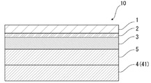
- FIG. 1 is a schematic diagram showing an example of a cross-sectional structure of an exterior material for an electricity storage device of the present disclosure
- BRIEF DESCRIPTION OF THE DRAWINGS FIG. 1 is a schematic diagram showing an example of a cross-sectional structure of an exterior material for an electricity storage device of the present disclosure
- BRIEF DESCRIPTION OF THE DRAWINGS FIG. 1 is a schematic diagram showing an example of a cross-sectional structure of an exterior material for an electricity storage device of the present disclosure
- BRIEF DESCRIPTION OF THE DRAWINGS FIG. 1 is a schematic diagram showing an example of a cross-sectional structure of an exterior material for an electricity storage device of the present disclosure
- BRIEF DESCRIPTION OF THE DRAWINGS FIG.
- FIG. 1 is a schematic diagram showing an example of a cross-sectional structure of an exterior material for an electricity storage device of the present disclosure
- FIG. 1 is a schematic diagram showing an example of a cross-sectional structure of an exterior material for an electricity storage device of the present disclosure
- It is a schematic diagram for demonstrating the corrosion-resistant evaluation method in an Example.
- FIG. 3 is a schematic diagram showing crystal grains and second phase particles in a cross section in the thickness direction of an aluminum alloy foil. This is a microscope image of the surface of an aluminum alloy foil observed after corrosion resistance evaluation, showing an example in which corrosion is suitably suppressed.
- FIG. 4 is a schematic diagram for explaining a method of measuring logarithmic decrement ⁇ E by rigid pendulum measurement;
- FIG. 4 is a schematic diagram for explaining a projecting portion formed inside a heat-sealed portion of a heat-sealable resin layer;
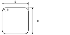
- FIG. 4 is a diagram showing a planar shape of a square punch used in a limit forming height test in an example of the present disclosure;
- the exterior material for an electricity storage device of the present disclosure is composed of a laminate including at least a substrate layer, a barrier layer, and a heat-fusible resin layer in this order, and the barrier layer contains Fe: 0.2% by mass. 2.0% by mass or less, Mg: 0.1% by mass or more and 5.0% by mass or less.
- the first heat-fusible resin layer constituting the surface of the laminate has a logarithmic attenuation rate ⁇ E at 140 ° C. in rigid pendulum measurement of 0.25 or less.
- the power storage device exterior material of the present disclosure by having the above configuration, it is excellent in moldability and effectively prevents corrosion of the aluminum alloy foil when electricity is applied in a state where the electrolytic solution is adhered. It is suppressed, and the insulation is also enhanced.
- the exterior material for an electricity storage device, the manufacturing method thereof, and the electricity storage device of the present disclosure will be described in detail below.
- the numerical range indicated by “-” means “more than” and “less than”.
- the notation of 2 to 15 mm means 2 mm or more and 15 mm or less.
- the exterior material 10 for an electricity storage device of the present disclosure is, for example, as shown in FIGS. consists of
- the base material layer 1 is the outermost layer
- the heat-fusible resin layer 4 is the innermost layer.
- the heat-sealable resin layers 4 of the electricity storage device exterior material 10 face each other, and the peripheral edges are heat-sealed.
- the electricity storage device element is accommodated in the space formed by .
- the barrier layer 3 is the reference
- the heat-fusible resin layer 4 side is inner than the barrier layer 3
- the base layer 1 side is more than the barrier layer 3. outside.
- the heat-fusible resin layer 4 is composed of a single layer or multiple layers. constitutes the surface of the laminate. 1 and 2, the heat-fusible resin layer 4 is composed of a single layer of the first heat-fusible resin layer 41, and the first heat-fusible resin layer 41 covers the surface of the laminate.
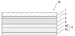
- Figure 3 illustrates the composing laminate structure. 3 to 5, the heat-fusible resin layer 4 is composed of multiple layers (two layers) of a first heat-fusible resin layer 41 and a second heat-fusible resin layer 42, The first heat-fusible resin layer 41 illustrates a laminated structure forming the surface of the laminated body.
- the heat-fusible resin layer 4 further includes a third heat-fusible resin layer, a fourth Another heat-fusible resin layer such as a heat-fusible resin layer may be provided on the barrier layer 3 side of the second heat-fusible resin layer 42 .
- the peripheral edges are heat-sealed while the first heat-fusible resin layers 41 of the electricity storage device exterior material 10 face each other.
- a power storage device element is housed in the space formed by the pressing.
- the barrier layer 3 of the power storage device exterior material of the present disclosure contains an aluminum alloy foil. That is, the barrier layer 3 of the power storage device exterior material of the present disclosure can be made of an aluminum alloy foil.
- the exterior material for an electricity storage device of the present disclosure which uses an aluminum alloy foil that satisfies a predetermined composition to be described later, has excellent moldability and effectively suppresses corrosion of the aluminum alloy foil.
- the logarithmic decrement ⁇ E at 140° C. is 0.25 or less, so that the first heat-fusible resin layer 41 is not crushed when heat-sealed. It is effectively suppressed, and the synergistic effect with the barrier layer (aluminum alloy foil) can improve the insulating properties of the exterior material for an electricity storage device.
- the electrical storage device exterior material 10 is provided between the base material layer 1 and the barrier layer 3 for the purpose of improving the adhesion between these layers, if necessary. It may have an adhesive layer 2 .
- the barrier layer 3 and the heat-fusible resin layer 4 for the purpose of improving the adhesion between these layers, if necessary, It may have an adhesive layer 5 .
- a surface coating layer 6 or the like may be provided on the outside of the base material layer 1 (the side opposite to the heat-fusible resin layer 4 side), if necessary.
- the thickness of the laminate that constitutes the power storage device exterior material 10 is not particularly limited, but from the viewpoint of cost reduction, energy density improvement, etc., it is, for example, 190 ⁇ m or less, preferably about 180 ⁇ m or less, about 155 ⁇ m or less, or about 120 ⁇ m or less. is mentioned.
- the thickness of the laminate constituting the power storage device exterior material 10 is preferably about 35 ⁇ m or more, about 45 ⁇ m or more, about 60 ⁇ m or more can be mentioned.
- the preferred range of the laminate constituting the power storage device exterior material 10 is, for example, about 35 to 190 ⁇ m, about 35 to 180 ⁇ m, about 35 to 155 ⁇ m, about 35 to 120 ⁇ m, about 45 to 190 ⁇ m, and about 45 to 180 ⁇ m. , about 45 to 155 ⁇ m, about 45 to 120 ⁇ m, about 60 to 190 ⁇ m, about 60 to 180 ⁇ m, about 60 to 155 ⁇ m, and about 60 to 120 ⁇ m, and particularly preferably about 60 to 155 ⁇ m.
- the thickness (total thickness) of the laminate constituting the power storage device exterior material 10 is the base layer 1, the adhesive layer 2 provided as necessary, the barrier layer 3, if necessary
- the ratio of the total thickness of the adhesive layer 5, the heat-fusible resin layer 4, and the surface coating layer 6 provided as necessary is preferably 90% or more, more preferably 95% or more, More preferably, it is 98% or more.
- the electrical storage device exterior material 10 of the present disclosure includes the base material layer 1, the adhesive layer 2, the barrier layer 3, the adhesive layer 5, and the heat-fusible resin layer 4, the electrical storage device exterior
- the ratio of the total thickness of each layer to the thickness (total thickness) of the laminate constituting the material 10 is preferably 90% or more, more preferably 95% or more, and still more preferably 98% or more.
- the power storage device exterior material 10 of the present disclosure is a laminate including the base material layer 1, the adhesive layer 2, the barrier layer 3, and the heat-fusible resin layer 4, the power storage device exterior material
- the ratio of the total thickness of each of these layers to the thickness (total thickness) of the laminate constituting 10 is, for example, 80% or more, preferably 90% or more, more preferably 95% or more, and further preferably 98% or more. can be done.
- the barrier layer 3 described later can usually be distinguished between MD (Machine Direction) and TD (Transverse Direction) in the manufacturing process.
- MD Machine Direction
- TD Transverse Direction
- the barrier layer 3 is made of an aluminum alloy foil
- linear streaks called rolling marks are formed on the surface of the metal foil in the rolling direction (RD) of the metal foil. Since the rolling marks extend along the rolling direction, the rolling direction of the metal foil can be grasped by observing the surface of the metal foil.
- the MD of the laminate usually matches the RD of the metal foil, so the surface of the metal foil of the laminate is observed to identify the rolling direction (RD) of the metal foil.
- the MD of the laminate can be specified.
- the TD of the laminate is perpendicular to the MD of the laminate, the TD of the laminate can also be specified.
- the MD of the electrical storage device exterior material cannot be specified due to the rolling marks of the aluminum alloy foil, it can be specified by the following method.
- a method for confirming the MD of the exterior material for an electricity storage device there is a method for confirming the sea-island structure by observing the cross section of the heat-fusible resin layer of the exterior material for the electricity storage device with an electron microscope.
- the MD can be determined as the direction parallel to the cross section in which the average diameter of the island shape in the direction perpendicular to the thickness direction of the heat-fusible resin layer is maximum.
- the cross section in the length direction of the heat-fusible resin layer is changed by 10 degrees from a direction parallel to the cross section in the length direction, and the direction is perpendicular to the cross section in the length direction. (10 cross sections in total) are observed with electron micrographs to confirm the sea-island structure.
- the shape of each individual island is observed.
- the linear distance connecting the leftmost end in the direction perpendicular to the thickness direction of the heat-sealable resin layer and the rightmost end in the perpendicular direction is defined as the diameter y.
- the average of the top 20 diameters y of the island shape is calculated in descending order of diameter y.
- the direction parallel to the cross section in which the average diameter y of the island shape is the largest is determined as the MD.
- the base material layer 1 is a layer provided for the purpose of exhibiting a function as a base material of an exterior material for an electric storage device.
- the base material layer 1 is located on the outer layer side of the exterior material for electrical storage devices.
- the material forming the base material layer 1 is not particularly limited as long as it functions as a base material, that is, at least has insulating properties.
- the base material layer 1 can be formed using, for example, a resin, and the resin may contain additives described later.
- the substrate layer 1 may be, for example, a resin film made of resin, or may be formed by applying resin.
- the resin film may be an unstretched film or a stretched film.
- stretched films include uniaxially stretched films and biaxially stretched films, with biaxially stretched films being preferred.
- stretching methods for forming a biaxially stretched film include successive biaxial stretching, inflation, and simultaneous biaxial stretching.
- Methods for applying the resin include a roll coating method, a gravure coating method, an extrusion coating method, and the like.
- resins forming the base material layer 1 include resins such as polyester, polyamide, polyolefin, epoxy resin, acrylic resin, fluororesin, polyurethane, silicon resin, phenolic resin, and modified products of these resins. Further, the resin forming the base material layer 1 may be a copolymer of these resins or a modified product of the copolymer. Furthermore, it may be a mixture of these resins.
- polyesters and polyamides are preferred as resins forming the base material layer 1 .
- polyester examples include polyethylene terephthalate, polybutylene terephthalate, polyethylene naphthalate, polybutylene naphthalate, polyethylene isophthalate, and copolymerized polyester.
- copolyester examples include copolyester having ethylene terephthalate as a main repeating unit.
- copolymer polyester polymerized with ethylene isophthalate with ethylene terephthalate as the main repeating unit hereinafter abbreviated after polyethylene (terephthalate / isophthalate)
- polyethylene (terephthalate / adipate) polyethylene (terephthalate / sodium sulfoisophthalate)
- polyethylene (terephthalate/sodium isophthalate) polyethylene (terephthalate/phenyl-dicarboxylate), polyethylene (terephthalate/decanedicarboxylate), and the like.
- These polyesters may be used singly or in combination of two or more.
- polyamide specifically, aliphatic polyamide such as nylon 6, nylon 66, nylon 610, nylon 12, nylon 46, copolymer of nylon 6 and nylon 66; terephthalic acid and / or isophthalic acid Hexamethylenediamine-isophthalic acid-terephthalic acid copolymer polyamide such as nylon 6I, nylon 6T, nylon 6IT, nylon 6I6T (I represents isophthalic acid, T represents terephthalic acid) containing structural units derived from, polyamide MXD6 (polymetallic Polyamides containing aromatics such as silylene adipamide); alicyclic polyamides such as polyamide PACM6 (polybis(4-aminocyclohexyl)methane adipamide); Copolymerized polyamides, polyesteramide copolymers and polyetheresteramide copolymers which are copolymers of copolymerized polyamides with polyesters or polyalkylene ether glycols; and polyamides such
- the substrate layer 1 preferably includes at least one of a polyester film, a polyamide film, and a polyolefin film, preferably includes at least one of a stretched polyester film, a stretched polyamide film, and a stretched polyolefin film, More preferably, at least one of an oriented polyethylene terephthalate film, an oriented polybutylene terephthalate film, an oriented nylon film, and an oriented polypropylene film is included, and the biaxially oriented polyethylene terephthalate film, biaxially oriented polybutylene terephthalate film, and biaxially oriented nylon film , biaxially oriented polypropylene film.
- the base material layer 1 may be a single layer, or may be composed of two or more layers.
- the substrate layer 1 may be a laminate obtained by laminating resin films with an adhesive or the like, or may be formed by co-extrusion of resin to form two or more layers. It may also be a laminate of resin films. A laminate of two or more resin films formed by coextrusion of resin may be used as the base material layer 1 without being stretched, or may be used as the base material layer 1 by being uniaxially or biaxially stretched.
- the laminate of two or more resin films in the substrate layer 1 include a laminate of a polyester film and a nylon film, a laminate of nylon films of two or more layers, and a laminate of polyester films of two or more layers. etc., preferably a laminate of a stretched nylon film and a stretched polyester film, a laminate of two or more layers of stretched nylon films, and a laminate of two or more layers of stretched polyester films.
- the substrate layer 1 is a laminate of two layers of resin films, a laminate of polyester resin films and polyester resin films, a laminate of polyamide resin films and polyamide resin films, or a laminate of polyester resin films and polyamide resin films.
- a laminate is preferred, and a laminate of polyethylene terephthalate film and polyethylene terephthalate film, a laminate of nylon film and nylon film, or a laminate of polyethylene terephthalate film and nylon film is more preferred.
- the polyester resin is resistant to discoloration when, for example, an electrolytic solution adheres to the surface. It is preferably located in the outermost layer.
- the two or more layers of resin films may be laminated via an adhesive.
- Preferred adhesives are the same as those exemplified for the adhesive layer 2 described later.
- the method for laminating two or more layers of resin films is not particularly limited, and known methods can be employed. Examples thereof include dry lamination, sandwich lamination, extrusion lamination, thermal lamination, and the like. A lamination method is mentioned.
- the thickness of the adhesive is, for example, about 2 to 5 ⁇ m.
- an anchor coat layer may be formed on the resin film and laminated.
- the anchor coat layer the same adhesives as those exemplified in the adhesive layer 2 described later can be used. At this time, the thickness of the anchor coat layer is, for example, about 0.01 to 1.0 ⁇ m.
- At least one of the surface and the inside of the substrate layer 1 may contain additives such as lubricants, flame retardants, antiblocking agents, antioxidants, light stabilizers, tackifiers, and antistatic agents. good. Only one type of additive may be used, or two or more types may be mixed and used.
- a lubricant exists on the surface of the base material layer 1 from the viewpoint of improving the moldability of the exterior material for an electricity storage device.
- the lubricant is not particularly limited, but preferably includes an amide-based lubricant.
- Specific examples of amide lubricants include saturated fatty acid amides, unsaturated fatty acid amides, substituted amides, methylolamides, saturated fatty acid bisamides, unsaturated fatty acid bisamides, fatty acid ester amides, and aromatic bisamides.
- saturated fatty acid amides include lauric acid amide, palmitic acid amide, stearic acid amide, behenic acid amide, and hydroxystearic acid amide.
- unsaturated fatty acid amides include oleic acid amide and erucic acid amide.
- substituted amides include N-oleyl palmitic acid amide, N-stearyl stearic acid amide, N-stearyl oleic acid amide, N-oleyl stearic acid amide, N-stearyl erucic acid amide and the like.
- methylolamide include methylol stearamide.
- saturated fatty acid bisamides include methylenebisstearic acid amide, ethylenebiscapric acid amide, ethylenebislauric acid amide, ethylenebisstearic acid amide, ethylenebishydroxystearic acid amide, ethylenebisbehenic acid amide, hexamethylenebisstearin. acid amide, hexamethylenebisbehenamide, hexamethylenehydroxystearic acid amide, N,N'-distearyladipic acid amide, N,N'-distearylsebacic acid amide and the like.
- unsaturated fatty acid bisamides include ethylenebisoleic acid amide, ethylenebiserucic acid amide, hexamethylenebisoleic acid amide, N,N'-dioleyladipic acid amide, and N,N'-dioleylsebacic acid amide. etc.
- fatty acid ester amides include stearamide ethyl stearate.
- aromatic bisamide include m-xylylenebisstearic acid amide, m-xylylenebishydroxystearic acid amide, N,N'-distearyl isophthalic acid amide and the like.
- Lubricants may be used singly or in combination of two or more.
- a lubricant exists on the surface of the base material layer 1, its amount is not particularly limited, but is preferably about 3 mg/m 2 or more, more preferably about 4 to 15 mg/m 2 , and still more preferably 5 to 14 mg. / m 2 degree.
- the lubricant present on the surface of the substrate layer 1 may be obtained by exuding the lubricant contained in the resin constituting the substrate layer 1, or by coating the surface of the substrate layer 1 with the lubricant.
- the thickness of the base material layer 1 is not particularly limited as long as it functions as a base material, but it is, for example, about 3 to 50 ⁇ m, preferably about 10 to 35 ⁇ m.
- the thickness of each resin film constituting each layer is preferably about 2 to 25 ⁇ m.
- the adhesive layer 2 is a layer provided between the base layer 1 and the barrier layer 3 as necessary for the purpose of enhancing the adhesiveness between them.
- the adhesive layer 2 is made of an adhesive that can bond the base material layer 1 and the barrier layer 3 together.
- the adhesive used to form the adhesive layer 2 is not limited, but may be any of a chemical reaction type, a solvent volatilization type, a hot melt type, a hot pressure type, and the like. Further, it may be a two-liquid curing adhesive (two-liquid adhesive), a one-liquid curing adhesive (one-liquid adhesive), or a resin that does not involve a curing reaction. Further, the adhesive layer 2 may be a single layer or multiple layers.
- the adhesive component contained in the adhesive include polyesters such as polyethylene terephthalate, polybutylene terephthalate, polyethylene naphthalate, polybutylene naphthalate, polyethylene isophthalate, and copolymerized polyester; polyether; polyurethane; epoxy resin; Phenolic resins; polyamides such as nylon 6, nylon 66, nylon 12, and copolymerized polyamides; polyolefin resins such as polyolefins, cyclic polyolefins, acid-modified polyolefins, and acid-modified cyclic polyolefins; polyvinyl acetate; cellulose; (meth)acrylic resins; polyimide; polycarbonate; amino resin such as urea resin and melamine resin; rubber such as chloroprene rubber, nitrile rubber and styrene-butadiene rubber; These adhesive components may be used singly or in combination of two or more.
- polyurethane adhesives are preferred.
- an appropriate curing agent can be used in combination with these adhesive component resins to increase the adhesive strength.
- the curing agent is selected from among polyisocyanates, polyfunctional epoxy resins, oxazoline group-containing polymers, polyamine resins, acid anhydrides, etc., depending on the functional groups of the adhesive component.
- polyurethane adhesives examples include polyurethane adhesives containing a main agent containing a polyol compound and a curing agent containing an isocyanate compound.
- Two-component curing type polyurethane adhesives using polyols such as polyester polyols, polyether polyols, and acrylic polyols as main agents and aromatic or aliphatic polyisocyanates as curing agents are preferred.
- the polyol compound it is preferable to use a polyester polyol having a hydroxyl group in a side chain in addition to the terminal hydroxyl group of the repeating unit.
- the adhesive layer 2 is formed of a polyurethane adhesive, the exterior material for an electric storage device is imparted with excellent electrolyte resistance, and even if the electrolyte adheres to the side surface, the base layer 1 is suppressed from being peeled off. .
- the adhesive layer 2 may contain other components as long as they do not impede adhesion, and may contain colorants, thermoplastic elastomers, tackifiers, fillers, and the like. Since the adhesive layer 2 contains a coloring agent, the exterior material for an electric storage device can be colored. Known substances such as pigments and dyes can be used as the colorant. In addition, only one type of colorant may be used, or two or more types may be mixed and used.
- the type of pigment is not particularly limited as long as it does not impair the adhesiveness of the adhesive layer 2.
- organic pigments include azo-based, phthalocyanine-based, quinacridone-based, anthraquinone-based, dioxazine-based, indigothioindigo-based, perinone-perylene-based, isoindolenine-based, and benzimidazolone-based pigments.
- pigments include carbon black, titanium oxide, cadmium, lead, chromium oxide, and iron pigments, as well as fine powder of mica and fish scale foil.
- carbon black is preferable, for example, in order to make the external appearance of the exterior material for a power storage device black.
- the average particle size of the pigment is not particularly limited, and is, for example, about 0.05 to 5 ⁇ m, preferably about 0.08 to 2 ⁇ m.
- the average particle size of the pigment is the median size measured with a laser diffraction/scattering particle size distribution analyzer.
- the content of the pigment in the adhesive layer 2 is not particularly limited as long as the power storage device exterior material is colored, and is, for example, about 5 to 60% by mass, preferably 10 to 40% by mass.
- the thickness of the adhesive layer 2 is not particularly limited as long as the substrate layer 1 and the barrier layer 3 can be adhered. , about 5 ⁇ m or less, and preferable ranges include about 1 to 10 ⁇ m, about 1 to 5 ⁇ m, about 2 to 10 ⁇ m, and about 2 to 5 ⁇ m.
- the colored layer is a layer provided as necessary between the base layer 1 and the barrier layer 3 (not shown).
- a colored layer may be provided between the base material layer 1 and the adhesive layer 2 and between the adhesive layer 2 and the barrier layer 3 . Further, a colored layer may be provided outside the base material layer 1 . By providing the colored layer, the exterior material for an electricity storage device can be colored.
- the colored layer can be formed, for example, by applying ink containing a coloring agent to the surface of the base material layer 1, the surface of the adhesive layer 2, or the surface of the barrier layer 3.
- ink containing a coloring agent such as pigments and dyes can be used as the colorant.
- pigments and dyes can be used as the colorant.
- only one type of colorant may be used, or two or more types may be mixed and used.
- colorant contained in the colored layer are the same as those exemplified in the [Adhesive layer 2] column.
- the barrier layer 3 is a layer that at least prevents permeation of moisture.
- the barrier layer 3 of the power storage device exterior material of the present disclosure contains an aluminum alloy foil.
- the aluminum alloy foil includes an aluminum alloy foil that satisfies the following composition: Fe (iron): 0.2 mass % or more and 2.0 mass % or less; Mg (magnesium): 0.1 mass % or more and 5.0 mass % or less.
- the main component of the aluminum alloy foil is Al (aluminum), and for example, 92.10% by mass or more is composed of aluminum.
- the aluminum alloy foil preferably contains Si (silicon). The silicon content is preferably less than or equal to about 0.50% by weight.
- the aluminum alloy foil may contain components other than Fe, Mg, and Al.
- Other components include, for example, inevitable impurities such as Si (silicon), Mn (manganese), Cu (copper), Cr (chromium), and Zn (zinc).
- the inevitable impurities in the aluminum alloy foil are, for example, 0.10% by mass or less individually and 0.40% by mass or less in total.
- the other component may be of one type or two or more types.
- the Fe content is below the lower limit (0.2% by mass)
- the distribution density of coarse intermetallic compounds is low
- the effect of grain refinement is low
- the final grain size distribution becomes uneven.
- the Fe content exceeds the upper limit (2.0% by mass)
- the grain refining effect is saturated or rather reduced, and the size of the Al—Fe intermetallic compound produced during casting becomes very large. , the elongation and rollability of the aluminum alloy foil are reduced.
- the content of Fe is set to the above range of 0.2% by mass or more and 2.0% by mass or less.
- the lower limit of the Fe content is preferably 0.5% by mass, and for the same reason, the lower limit of the Fe content is preferably 1.0% by mass and the upper limit is 1.8% by mass. .
- Mg dissolves in aluminum and can increase the strength of the aluminum alloy foil through solid-solution strengthening.
- Mg easily dissolves in aluminum, even if it is contained together with Fe, there is little risk of coarsening of intermetallic compounds and deterioration of formability and rollability.
- the Mg content is less than the lower limit (0.1% by mass)
- the improvement in strength is insufficient
- the upper limit 5.0% by mass
- the aluminum alloy foil becomes hard, resulting in a decrease in rollability and formability. invite.
- a particularly preferred lower limit is 0.5% by mass.
- the Mg content exceeds 5.0% by mass, the aluminum alloy foil becomes hard and the formability and rollability deteriorate, but it is possible to obtain an aluminum alloy foil having a very high strength. It is desirable that the content of Mg is in the range of more than 0.5% by mass and 4.5% by mass or less. In addition, the addition of Mg improves the corrosion resistance of the exterior material for an electric storage device to the electrolytic solution. Although the details of the mechanism are not clear, the larger the amount of Mg added, the more difficult it is for the aluminum alloy foil to react with lithium or the like in the electrolytic solution, which can suppress the pulverization of the aluminum alloy foil and the formation of through holes.
- Si may be added for the purpose of increasing the strength of the aluminum alloy foil if it is a trace amount, but in the present disclosure, by making it 0.5% by mass or less, the Al generated during casting - The size of the Fe--Si intermetallic compound is reduced, and the elongation and formability of the aluminum alloy foil are enhanced. Therefore, even when the thickness of the aluminum alloy foil is thin, fracture originating from the intermetallic compound is less likely to occur, and the rollability is improved. In addition, by not adding a large amount of Si to an alloy with a high Mg content, the amount of Mg—Si precipitates formed is reduced, and it is difficult to reduce the rollability and the amount of Mg in solid solution, resulting in a decrease in strength. become difficult.
- the Si content it is desirable to suppress the Si content to 0.2% by mass or less.
- the lower limit of the Si content is desirably 0.001% by mass, more desirably 0.005% by mass. It should be noted that the lower the Si content, the better the formability, rollability, grain refinement degree, and ductility.
- the aluminum alloy foil can contain unavoidable impurities such as Cu and Mn. It is desirable that the content of these impurities is, for example, 0.1% by mass or less. In addition, as the present disclosure, the upper limit of the content of the inevitable impurities is not limited to the above numerical value.
- Mn is difficult to form a solid solution in aluminum, unlike Mg, it cannot be expected to significantly increase the strength of the aluminum alloy foil by solid solution strengthening. Also, if a large amount of Mn is added to an alloy with a high Fe content, there is a high risk of coarsening of intermetallic compounds and formation of Al-Fe-Mn-based giant intermetallic compounds, resulting in deterioration of rollability and formability. There is fear.
- the Mn content is desirably 0.1% by mass or less.
- the Mn content is more desirably 0.08% by mass or less.
- the lower limit of the Mn content is desirably 0.001% by mass, more desirably 0.005% by mass.
- Mn manganese : It is preferable to satisfy a composition of 0.1% by mass or less, more preferably to satisfy a composition of Mn: 0.01% by mass or more and 0.1% by mass or less, Mn: 0.01% by mass or more and 0.08 It is more preferable to satisfy the composition of mass % or less.
- ⁇ Fe 0.2% by mass or more and 2.0% by mass or less Fe crystallizes as an Al-Fe intermetallic compound during casting, and if the size of the compound is large, it becomes a recrystallization site during annealing. It has the effect of refining crystal grains.
- the content of Fe is set within the above range.
- the lower limit of the Fe content is preferably 0.5% by mass, and for the same reason, the lower limit of the Fe content is preferably 1.0% by mass and the upper limit is 1.8% by mass. .
- Mg dissolves in aluminum and can increase the strength of the soft foil by solid-solution strengthening.
- Mg since Mg is easily dissolved in aluminum, even if it is contained together with Fe, there is little risk of coarsening of intermetallic compounds and deterioration of formability and rollability. If the Mg content is below the lower limit, the strength will not be sufficiently improved, and if the Mg content is above the upper limit, the aluminum alloy foil will become hard, resulting in reduced rollability and formability.
- a particularly preferable range for the Mg content is 0.5% by mass or more and 5.0% by mass or less. It was also confirmed that the addition of Mg improves the corrosion resistance of the lithium ion secondary battery to the electrolytic solution.
- the lower limit of the Mg content is desirably 0.5% by mass, even if a particularly clear improvement in corrosion resistance is expected, although formability is slightly reduced.
- Si 0.5% by mass or less
- Si may be added for the purpose of increasing the strength of the foil if it is a trace amount, but in the present disclosure, the Si content is 0.5% or less .
- the size of the Al-Fe-Si intermetallic compound generated during casting is reduced, the elongation and formability of the foil are enhanced, and even when the foil thickness is thin, breakage starting from the intermetallic compound is less likely to occur.
- the content is preferably 0.5% by mass or less because the rollability is also improved.
- the amount of Mg—Si based precipitates produced is reduced, making it difficult for deterioration of rollability and the amount of Mg in solid solution to occur, and strength to decrease.
- unavoidable impurities such as Cu and Mn can be included.
- the amount of each element of these unavoidable impurities is desirably 0.1% by mass or less.
- the upper limit of the content of the inevitable impurities is not limited to the above numerical value.
- Mn is difficult to form a solid solution in aluminum, unlike Mg, it cannot be expected to greatly increase the strength of the soft foil by solid-solution strengthening.
- the Mn content is desirably 0.1% by mass or less.
- each orientation density of the copper orientation and R orientation of the texture is 15 or less
- the texture has a great influence on the mechanical properties and formability of the foil.
- the surface Mg concentration is 5.0 atomic percent or more and the oxide film thickness is 80 ⁇ or more (Mg: 0.1% by mass or more and 1.5% by mass or less)
- Mg 0.1% by mass or more and 1.5% by mass or less
- the details of the mechanism are not clear, it has been confirmed that the Mg concentration on the foil surface and the thickness of the oxide film contribute to the corrosion resistance of the lithium ion secondary battery to the electrolyte. Corrosion resistance is improved due to the high Mg concentration on the foil surface and the formation of a thick oxide film. Therefore, when Mg is 0.1% by mass or more and 1.5% by mass or less, it is desirable to set the Mg concentration on the aluminum foil surface to 5.0 atomic percent or more and the oxide film thickness to be 80 ⁇ or more.
- the surface Mg concentration is 15.0 atomic percent or more and the oxide film thickness is 200 ⁇ or more. More desirably, the surface Mg concentration is 20.0 atomic percent or more.
- the surface Mg concentration is the Mg concentration in the surface portion from the outermost surface to a depth of 8 nm, and the Mg concentration is the amount with respect to the total of 100 atomic % of all elements.
- the surface Mg concentration is 15.0 atomic percent or more and the oxide film thickness is 120 ⁇ or more (when Mg: more than 1.5% by mass and 5.0% by mass or less)
- the Mg concentration on the foil surface and the thickness of the oxide film contribute to the corrosion resistance of the lithium ion secondary battery to the electrolytic solution. Corrosion resistance is improved due to the high Mg concentration on the foil surface and the formation of a thick oxide film. Therefore, when the Mg content is more than 1.5% by mass and 5.0% by mass or less, it is desirable to set the Mg concentration on the aluminum foil surface to 15.0 atomic percent or more and the oxide film thickness to be 120 ⁇ or more. More preferably, the surface Mg concentration is 20.0 atomic percent or more and the oxide film thickness is 220 ⁇ or more. More desirably, the surface Mg concentration is 25.0 atomic percent or more.
- L1 is the length of the large-angle grain boundary per unit area
- L2 is the length of the small-angle grain boundary measured by the backscattered electron diffraction method.
- the proportion of high-angle grain boundaries (HAGB) and low-angle grain boundaries (LAGB) in the recrystallized grain structure after annealing affects the elongation and formability of the foil.
- HAGB high-angle grain boundaries
- LAGB low-angle grain boundaries
- ⁇ Tensile strength 110 MPa or more and 180 MPa or less (when Mg: 0.1 mass% or more and 1.5 mass% or less) Mg: When it is 0.1% by mass or more and 1.5% by mass or less, a tensile strength of 110 MPa or more is required to dramatically improve the impact resistance and puncture strength of existing foils such as JIS A8079 and 8021. is required. It is preferable that the tensile strength be 180 MPa or less. Tensile strength can be achieved by selection of composition and optimization of grain size.
- Tensile strength 180 MPa or more (when Mg: more than 1.5% by mass and 5.0% by mass or less) Mg: When more than 1.5% by mass and 5.0% by mass or less, a tensile strength of 180 MPa or more is required to dramatically improve the impact resistance and puncture strength of existing foils such as JIS A8079 and 8021. is preferred. For the same reason, the tensile strength is desirably 200 MPa or more. However, the higher the tensile strength, the lower the moldability. Therefore, when the moldability is emphasized, it is better to suppress the tensile strength. As noted above, tensile strength can be achieved through composition selection and grain size optimization.
- ⁇ Average crystal grain size 25 ⁇ m or less
- the average grain size is desirably 25 ⁇ m or less in order to achieve high elongation properties and accompanying high formability.
- the average grain size can be achieved by selecting the composition and manufacturing conditions that optimize the homogenization treatment and cold rolling rate.
- a preferred composition of the aluminum alloy foil includes, for example, those satisfying the compositions of Specific Examples 1 and 2 below.
- Si 0.1% by mass or more and 0.5% by mass or less Fe: 0.2% by mass or more and 2.0% by mass or less Mg: 0.1% by mass or more and 5.0% by mass or less Mn: 0.1 % by mass, Cu: 0.0% by mass, Cr: 0.0% by mass, Zr: 0.0% by mass, and other unavoidable impurities are 0.05% by mass or less individually and 0.15% by mass in total. % or less, and the balance is more preferably Al.
- the aluminum alloy foil contains Si: 0.5% by mass or less, Fe: 0.2% by mass or more and 2.0% by mass or less, Mg: 0.1% by mass or more and 5.0% by mass or less, Mn: 0.5% by mass or less. 1% by mass, Cu: 0.0% by mass, Cr: 0.0% by mass, Zr: 0.0% by mass, and other inevitable impurities are 0.05% by mass or less individually and 0.15% in total % by mass or less, and the balance is Al.
- the tensile strength of the aluminum alloy foil is 100 MPa or more, and 200 MPa or more. is more desirable.
- the upper limit of tensile strength is desirably 350 MPa.
- the tensile strength is desirably 200 MPa or more and 350 MPa or less, and more desirably 200 MPa or more and 310 MPa or less.
- the higher the tensile strength the lower the moldability. Therefore, when the moldability is important, it is better to suppress the tensile strength.
- the aluminum alloy foil has a tensile strength of 100 MPa or more and 180 MPa or less, measured on a JIS No. 5 test piece in accordance with JIS Z2241:2011. is preferred. Specifically, the tensile strength is measured by the method described in Examples. The tensile strength of aluminum alloy foil can be achieved by selecting the composition and optimizing the grain size.
- the effect of elongation on the formability of aluminum alloy foil varies greatly depending on the forming method, and elongation alone does not determine formability.
- the aluminum alloy foil preferably has an elongation at break of 10% or more, more preferably 15% or more, as measured on a JIS No. 5 test piece in accordance with JIS Z2241:2011.
- the upper limit of breaking elongation is desirably 40%, more desirably 30%.
- the elongation at break is desirably 0% to 40%, more desirably 15% to 40%, and even more desirably 15% to 30%.
- the elongation at break is measured by the method described in Examples.
- the elongation properties of the aluminum alloy foil can be achieved by selecting the composition and refining the grain size.
- the aluminum alloy foil that satisfies the composition and properties as described above can be obtained, for example, by adjusting the composition based on an aluminum alloy having a composition in the alloy number A5000 series of JIS H4000:2014, and using a known method for producing an aluminum alloy foil, for example: , melting, homogenization, hot rolling, cold rolling, intermediate annealing, cold rolling, and final annealing.
- a known method for producing an aluminum alloy foil for example: , melting, homogenization, hot rolling, cold rolling, intermediate annealing, cold rolling, and final annealing.
- the description in Japanese Patent Application Laid-Open No. 2005-163077 can be referred to.
- the analysis of each chemical component contained in the aluminum alloy foil is performed by the analytical test specified in JIS H4160-1994.
- an aluminum alloy ingot satisfying the composition of Fe: 0.2% by mass to 2.0% by mass and Mg: 0.1% by mass to 5.0% by mass is cast by a conventional method such as semi-continuous casting. Cast by The obtained ingot is homogenized at 480-540° C. for 6-12 hours.
- the homogenization treatment of aluminum materials is performed at 400 to 600 ° C. for a long time (for example, about 12 hours), but considering grain refinement by adding Fe as in the present disclosure, heat treatment at 480 to 540 ° C. for 6 hours or more. It is desirable to If the temperature is less than 480°C, grain refinement is insufficient, and if it exceeds 540°C, the grains become coarse. If the treatment time is less than 6 hours, homogenization will be insufficient.
- Hot rolling is performed to obtain an aluminum alloy plate with the desired thickness.
- Hot rolling can be performed by a conventional method, and the coiling temperature for hot rolling is desirably higher than the recrystallization temperature, specifically 300° C. or higher.
- the recrystallization temperature specifically 300° C. or higher.
- fine Al-Fe intermetallic compounds of 0.3 ⁇ m or less are precipitated, and recrystallized grains and fiber grains coexist after hot rolling, resulting in non-uniform crystal grain sizes after intermediate annealing and final annealing. It is not desirable because there is a concern that the elongation characteristics will deteriorate.
- the aluminum alloy foil of the present disclosure After hot rolling, cold rolling, intermediate annealing, and final cold rolling are performed to obtain the aluminum alloy foil of the present disclosure by making the thickness 5 to 100 ⁇ m. It is desirable that the final cold rolling reduction be 90% or more.
- intermediate annealing may not be performed during cold rolling, it may be performed in some cases.
- intermediate annealing There are two types of intermediate annealing: batch annealing, in which the coil is placed in a furnace and held for a certain period of time, and rapid heating and cooling of the material in a continuous annealing line (hereinafter referred to as CAL annealing).
- batch annealing in which the coil is placed in a furnace and held for a certain period of time
- CAL annealing rapid heating and cooling of the material in a continuous annealing line
- any method may be used, but CAL annealing is desirable for grain refinement and high strength, and batch annealing is desirable for formability.
- heating rate 10 to 250° C./sec
- heating temperature 400° C. to 550° C.
- no holding time or holding time 5 seconds or less
- Cooling rate A condition of 20 to 200° C./sec
- the presence or absence of intermediate annealing, the conditions for performing intermediate annealing, and the like are not limited to specific ones.
- final annealing is performed to make a soft foil.
- Final annealing after foil rolling may generally be performed at 250°C to 400°C.
- the softening is insufficient, and there is a concern that the concentration of Mg on the foil surface will be insufficient and the corrosion resistance will decrease. If the temperature exceeds 400° C., Mg may be excessively concentrated on the foil surface, discoloring the foil, or the properties of the oxide film may change to cause minute cracks, resulting in deterioration of corrosion resistance. If the final annealing time is less than 5 hours, the effect of the final annealing is insufficient.
- An aluminum alloy ingot is cast by a conventional method such as a semi-continuous casting method.
- the aluminum alloy ingot contains Fe: 0.2% by mass or more and 2.0% by mass or less, Mg: 0.1% by mass or more and 5.0% by mass or less, and the balance contains Al and unavoidable impurities. It has a composition of Mn: 0.1% by mass or less.
- the obtained ingot is homogenized at 480-540° C. for 6-12 hours.
- Homogenization treatment 450 to 550 ° C
- the purpose of the homogenization treatment is to eliminate micro-segregation in the ingot and to adjust the distribution of intermetallic compounds, and is a very important treatment for finally obtaining the desired crystal grain structure.
- the homogenization treatment of aluminum materials is performed at 400 to 600° C. for a long time, but in the present invention, it is necessary to consider grain refinement by adding Fe.
- the temperature is less than 450° C., precipitation of Fe becomes insufficient, and there is concern about coarsening of crystal grains during the final annealing.
- the ratio of in-situ recrystallization increases, the ratio of LAGB increases, and there is concern about a decrease in L1/L2.
- crystallized substances grow remarkably, leading to coarsening of crystal grains and deterioration of formability during the final annealing. It is necessary to secure at least 3 hours or more for the homogenization treatment. If the time is less than 3 hours, precipitation is not sufficient and the density of the fine intermetallic compounds is lowered.
- the temperature is 480 to 520° C. and the time is 5 hours or more.
- Hot rolling is performed to obtain an aluminum alloy plate with the desired thickness.
- Hot rolling can be performed by a conventional method, and the coiling temperature for hot rolling is desirably higher than the recrystallization temperature, specifically 300° C. or higher. If the temperature is less than 300° C., fine Al—Fe intermetallic compounds of 0.3 ⁇ m or less are deposited.
- recrystallized grains and fiber grains coexist after hot rolling, and the crystal grain size after intermediate annealing and final annealing may become non-uniform, resulting in deterioration in elongation characteristics, which is not desirable.
- intermediate annealing After hot rolling, cold rolling, intermediate annealing, and final cold rolling are performed to obtain the aluminum alloy foil of the present invention with a thickness of 5 to 100 ⁇ m.
- intermediate annealing There are two types of intermediate annealing: batch annealing, in which coils are placed in a furnace and held for a certain period of time, and rapid heating and rapid cooling in a continuous annealing line (hereinafter referred to as CAL annealing). Any method may be used when the intermediate annealing is applied, but CAL annealing is preferable for refining the crystal grains and increasing the strength.
- batch annealing is preferable if formability is given priority.
- conditions of 300 to 400° C. for 3 hours or more can be adopted.
- CAL annealing the following conditions shall be adopted: heating rate: 10 to 250°C/sec, heating temperature: 400°C to 550°C, no holding time or holding time: 5 seconds or less, cooling rate: 20 to 200°C/sec. can be done.
- the presence or absence of intermediate annealing, the conditions for performing intermediate annealing, and the like are not limited to specific ones.
- Final cold rolling reduction 84.0% or more and 97.0% or less
- the more desirable final cold rolling reduction range is 90.0% or more and 93.0% or less.
- final annealing is performed to obtain a soft foil.
- Final annealing after foil rolling may generally be performed at 250°C to 400°C.
- the temperature is more preferably 350°C to 400°C. If the final annealing temperature is low, the softening is insufficient, and there is concern that the L1/L2 ratio will decrease and the densities of each orientation of the Copper orientation and the R orientation will increase.
- the concentration of Mg on the foil surface and the growth of the oxide film will be insufficient, resulting in a decrease in corrosion resistance.
- Mg may be excessively concentrated on the foil surface, discoloring the foil, or the properties of the oxide film may change to cause minute cracks, resulting in deterioration of corrosion resistance. If the final annealing time is less than 5 hours, the effect of the final annealing is insufficient.
- the obtained aluminum alloy foil has a tensile strength of 110 MPa or more and 180 MPa or less and a breaking elongation of 10% or more at room temperature when Mg: 0.1 mass% or more and 1.5 mass% or less.
- the tensile strength is 180 MPa or more and the elongation at break is 15% or more.
- the average crystal grain size is 25 ⁇ m or less. The average grain size can be determined by the cutting method specified in JIS G0551.
- the aluminum alloy foil has a thickness of, for example, about 85 ⁇ m or less, further about 50 ⁇ m or less, or even about 40 ⁇ m or less, which is a very thin aluminum alloy foil, the aluminum alloy foil is laminated on the exterior material for the power storage device, and formed. Pinholes and cracks are less likely to occur when pressed, and the exterior material for an electric storage device can be provided with excellent moldability.
- the average diameter y of the second phase particles 3b in the aluminum alloy foil (barrier layer 3) is 10.0 ⁇ m or less, so that the thickness of the aluminum alloy foil is, for example, about 85 ⁇ m or less, or even about It is 50 ⁇ m or less, further about 40 ⁇ m or less, and even if the total thickness of the exterior material for an electric storage device is as thin as the above, for example, pinholes and cracks are unlikely to occur during molding, and excellent moldability can be achieved. I have.
- the average diameter y is more preferably about 1.0 to 8.0 ⁇ m, more preferably about 1.0 to 6.0 ⁇ m. Since FIG. 7 is a schematic diagram, drawing is omitted, and 100 second phase particles 3b are not drawn.
- the second phase particles contained in the aluminum alloy foil refer to intermetallic compound particles that exist in the aluminum alloy, and include crystallized phases that are separated by rolling and precipitation that precipitates during homogenization treatment and annealing. phase particles.
- crystal grains When observing a cross section of an aluminum alloy foil in the MD direction and the thickness direction with a scanning electron microscope (SEM), crystal grains usually draw boundaries that contact multiple crystals. In contrast, second phase particles are usually single crystal boundaries. In addition, since the crystal grains and the second phase particles have different phases, they are characterized by different colors on the SEM image. Furthermore, when a cross section in the MD direction and the thickness direction of the aluminum alloy foil layer is observed with a scanning electron microscope, only the second phase particles are observed due to the phase difference between the crystal grains and the second phase particles. appears black, making observation easier.
- SEM scanning electron microscope
- the average crystal grain size in the aluminum alloy foil is preferably 25.0 ⁇ m or less, more preferably 20.0 ⁇ m or less, still more preferably 10.0 ⁇ m or less, and preferably 1 0 ⁇ m or more, 3.0 ⁇ m or more, more preferably 9.0 ⁇ m or more.
- Preferred ranges of the average crystal grain size are about 1.0 to 25.0 ⁇ m, about 1.0 to 20.0 ⁇ m, about 1.0 to 10.0 ⁇ m, about 3.0 to 25.0 ⁇ m, 3.0 about 20.0 ⁇ m, about 3.0 to 10.0 ⁇ m, about 9.0 to 25.0 ⁇ m, about 9.0 to 20.0 ⁇ m, and about 9.0 to 10.0 ⁇ m.
- the average crystal grain size in the aluminum alloy foil is 25.0 ⁇ m or less, and the diameter y of the second phase particles 3b is the above value, so that the formability of the exterior material for an electricity storage device described later is further improved. can be enhanced.
- the average crystal grain size in the aluminum alloy foil is obtained by observing a cross section of the aluminum alloy foil in the thickness direction with a scanning electron microscope (SEM), and 100 aluminum alloy crystal grains 3a located within the field of view.
- SEM scanning electron microscope
- 100 aluminum alloy crystal grains 3a located within the field of view.
- 100 It means the average value of the maximum diameter x of individual crystal grains. Since FIG. 7 is a schematic diagram, drawing is omitted and 100 crystal grains 3a are not drawn.
- the thickness of the aluminum alloy foil is sufficient to exhibit at least a function as a barrier layer that suppresses the infiltration of moisture in the exterior material for an electric storage device.
- the upper limit of the thickness of the aluminum alloy foil is, for example, preferably about 85 ⁇ m or less, more preferably about 50 ⁇ m or less, even more preferably about 45 ⁇ m or less, particularly preferably about 40 ⁇ m or less, and the lower limit is preferably about 10 ⁇ m or more, more preferably about 20 ⁇ m or more, and more preferably about 25 ⁇ m or more.
- about 10 to 45 ⁇ m, about 10 to 40 ⁇ m, about 20 to 85 ⁇ m, about 20 to 50 ⁇ m, about 20 to 45 ⁇ m, about 20 to 40 ⁇ m, about 25 to 85 ⁇ m, about 25 to 50 ⁇ m, about 25 to 45 ⁇ m, about 25 to 40 ⁇ m is mentioned.
- the aluminum alloy foil is provided with a corrosion-resistant film in order to prevent dissolution and corrosion of the aluminum alloy foil.
- the aluminum alloy foil may be provided with a corrosion resistant coating on both sides.
- the corrosion-resistant film includes, for example, hydrothermal transformation treatment such as boehmite treatment, chemical conversion treatment, anodizing treatment, plating treatment such as nickel and chromium, and corrosion prevention treatment such as coating with a coating agent on aluminum alloy foil.
- the treatment for forming the corrosion-resistant film one type may be performed, or two or more types may be used in combination. Also, not only one layer but also multiple layers can be used.
- the hydrothermal transformation treatment and the anodizing treatment are treatments in which the surface of the metal foil is dissolved with a treating agent to form a metal compound having excellent corrosion resistance. These treatments are sometimes included in the definition of chemical conversion treatment.
- the aluminum alloy foil has a corrosion-resistant film
- the aluminum alloy foil includes the corrosion-resistant film.
- the corrosion-resistant film prevents delamination between the aluminum alloy foil and the substrate layer during the molding of the exterior material for an electric storage device. Prevents dissolution, corrosion, and dissolution and corrosion of aluminum oxide present on the surface of the aluminum alloy foil, and improves the adhesiveness (wettability) of the surface of the aluminum alloy foil. The effect of preventing delamination with the foil and preventing delamination between the base material layer and the aluminum alloy foil during molding is shown.
- corrosion-resistant coatings formed by chemical conversion treatment are known, and are mainly composed of at least one of phosphates, chromates, fluorides, triazinethiol compounds, and rare earth oxides. and corrosion-resistant coatings containing.
- Examples of chemical conversion treatments using phosphate and chromate include chromic acid chromate treatment, phosphoric acid chromate treatment, phosphoric acid-chromate treatment, and chromate treatment.
- Examples of compounds include chromium nitrate, chromium fluoride, chromium sulfate, chromium acetate, chromium oxalate, chromium biphosphate, chromium acetyl acetate, chromium chloride, potassium chromium sulfate, and the like.
- Phosphorus compounds used for these treatments include sodium phosphate, potassium phosphate, ammonium phosphate, polyphosphoric acid, and the like.
- Examples of the chromate treatment include etching chromate treatment, electrolytic chromate treatment, coating-type chromate treatment, etc., and coating-type chromate treatment is preferred.
- the inner layer side surface of the barrier layer (for example, aluminum alloy foil) is first subjected to a well-known method such as an alkali immersion method, an electrolytic cleaning method, an acid cleaning method, an electrolytic acid cleaning method, an acid activation method, or the like.
- metal phosphate such as Cr (chromium) phosphate, Ti (titanium) phosphate, Zr (zirconium) phosphate, Zn (zinc) phosphate is applied to the degreased surface.
- a processing solution mainly composed of a salt and a mixture of these metal salts a processing solution mainly composed of a non-metal phosphate salt and a mixture of these non-metal salts, or a mixture of these and a synthetic resin.
- This is a treatment in which a treatment liquid composed of a mixture is applied by a well-known coating method such as a roll coating method, a gravure printing method, or an immersion method, and then dried.
- Various solvents such as water, alcohol-based solvents, hydrocarbon-based solvents, ketone-based solvents, ester-based solvents, and ether-based solvents can be used as the treatment liquid, and water is preferred.
- the resin component used at this time includes polymers such as phenolic resins and acrylic resins. and the chromate treatment used.
- the repeating units represented by the following general formulas (1) to (4) may be contained singly or in any combination of two or more. good too.
- the acrylic resin is polyacrylic acid, acrylic acid methacrylic acid ester copolymer, acrylic acid maleic acid copolymer, acrylic acid styrene copolymer, or derivatives thereof such as sodium salts, ammonium salts, and amine salts. is preferred.
- derivatives of polyacrylic acid such as ammonium salt, sodium salt or amine salt of polyacrylic acid are preferred.
- polyacrylic acid means a polymer of acrylic acid.
- the acrylic resin is preferably a copolymer of acrylic acid and dicarboxylic acid or dicarboxylic anhydride, and the ammonium salt, sodium salt, Alternatively, it is also preferably an amine salt. Only one type of acrylic resin may be used, or two or more types may be mixed and used.
- X represents a hydrogen atom, hydroxy group, alkyl group, hydroxyalkyl group, allyl group or benzyl group.
- R 1 and R 2 are the same or different and represent a hydroxy group, an alkyl group or a hydroxyalkyl group.
- alkyl groups represented by X, R 1 and R 2 in general formulas (1) to (4) include methyl group, ethyl group, n-propyl group, isopropyl group, n-butyl group, isobutyl group, A linear or branched alkyl group having 1 to 4 carbon atoms such as a tert-butyl group can be mentioned.
- hydroxyalkyl groups represented by X, R 1 and R 2 include hydroxymethyl group, 1-hydroxyethyl group, 2-hydroxyethyl group, 1-hydroxypropyl group, 2-hydroxypropyl group, 3- A straight or branched chain having 1 to 4 carbon atoms substituted with one hydroxy group such as hydroxypropyl group, 1-hydroxybutyl group, 2-hydroxybutyl group, 3-hydroxybutyl group and 4-hydroxybutyl group An alkyl group is mentioned.
- the alkyl groups and hydroxyalkyl groups represented by X, R 1 and R 2 may be the same or different.
- X is preferably a hydrogen atom, a hydroxy group or a hydroxyalkyl group.
- the number average molecular weight of the aminated phenol polymer having repeating units represented by formulas (1) to (4) is, for example, preferably about 500 to 1,000,000, more preferably about 1,000 to 20,000. more preferred.
- the aminated phenol polymer is produced, for example, by polycondensing a phenol compound or naphthol compound and formaldehyde to produce a polymer comprising repeating units represented by the general formula (1) or general formula (3), followed by formaldehyde. and an amine (R 1 R 2 NH) to introduce a functional group (--CH 2 NR 1 R 2 ) into the polymer obtained above.
- An aminated phenol polymer is used individually by 1 type or in mixture of 2 or more types.
- the corrosion-resistant film is formed by a coating-type corrosion prevention treatment in which a coating agent containing at least one selected from the group consisting of rare earth element oxide sol, anionic polymer, and cationic polymer is applied.
- a coating agent containing at least one selected from the group consisting of rare earth element oxide sol, anionic polymer, and cationic polymer is applied.
- the coating agent may further contain phosphoric acid or a phosphate, a cross-linking agent for cross-linking the polymer.
- rare earth element oxide sol rare earth element oxide fine particles (for example, particles having an average particle size of 100 nm or less) are dispersed in a liquid dispersion medium.
- rare earth element oxides include cerium oxide, yttrium oxide, neodymium oxide, and lanthanum oxide, and cerium oxide is preferable from the viewpoint of further improving adhesion.
- the rare earth element oxides contained in the corrosion-resistant coating can be used singly or in combination of two or more.
- various solvents such as water, alcohol solvents, hydrocarbon solvents, ketone solvents, ester solvents, and ether solvents can be used, with water being preferred.
- the cationic polymer include polyethyleneimine, an ionic polymer complex composed of a polymer containing polyethyleneimine and carboxylic acid, a primary amine-grafted acrylic resin obtained by graft-polymerizing a primary amine to an acrylic backbone, polyallylamine, or a derivative thereof. , aminated phenols and the like are preferred.
- the anionic polymer is preferably poly(meth)acrylic acid or a salt thereof, or a copolymer containing (meth)acrylic acid or a salt thereof as a main component.
- the cross-linking agent is preferably at least one selected from the group consisting of a compound having a functional group such as an isocyanate group, a glycidyl group, a carboxyl group, or an oxazoline group, and a silane coupling agent.
- the phosphoric acid or phosphate is preferably condensed phosphoric acid or condensed phosphate.
- fine particles of metal oxides such as aluminum oxide, titanium oxide, cerium oxide, and tin oxide, and barium sulfate are dispersed in phosphoric acid, which is applied to the surface of the barrier layer. C. or more, and those formed by performing baking processing are mentioned.
- the corrosion-resistant film may, if necessary, have a laminated structure in which at least one of a cationic polymer and an anionic polymer is further laminated.
- a cationic polymer and anionic polymers include those described above.
- the analysis of the composition of the corrosion-resistant coating can be performed using, for example, time-of-flight secondary ion mass spectrometry.
- the amount of the corrosion - resistant film formed on the surface of the aluminum alloy foil in the chemical conversion treatment is not particularly limited. is about 0.5 to 50 mg, preferably about 1.0 to 40 mg in terms of chromium, the phosphorus compound is about 0.5 to 50 mg, preferably about 1.0 to 40 mg in terms of phosphorus, and aminated phenol polymer is contained in a ratio of, for example, about 1.0 to 200 mg, preferably about 5.0 to 150 mg.
- the thickness of the corrosion-resistant coating is not particularly limited, but is preferably about 1 nm to 20 ⁇ m, more preferably 1 nm to 100 nm, from the viewpoint of cohesion of the coating and adhesion to the barrier layer and the heat-sealable resin layer. about 1 nm to 50 nm, more preferably about 1 nm to 50 nm.
- the thickness of the corrosion-resistant film can be measured by observation with a transmission electron microscope, or by a combination of observation with a transmission electron microscope and energy dispersive X-ray spectroscopy or electron beam energy loss spectroscopy.
- secondary ions composed of Ce, P and O for example, at least one of Ce 2 PO 4 + and CePO 4 ⁇ species
- secondary ions composed of Cr, P, and O eg, at least one of CrPO 2 + and CrPO 4 ⁇
- a solution containing a compound used for forming a corrosion-resistant film is applied to the surface of the aluminum alloy foil by a bar coating method, a roll coating method, a gravure coating method, an immersion method, or the like. is carried out by heating so that the temperature of is about 70 to 200°C.
- the aluminum alloy foil may be previously subjected to degreasing treatment by an alkali immersion method, an electrolytic cleaning method, an acid cleaning method, an electrolytic acid cleaning method, or the like. By performing the degreasing treatment in this way, it becomes possible to perform the chemical conversion treatment on the surface of the aluminum alloy foil more efficiently.
- an acid degreasing agent obtained by dissolving a fluorine-containing compound in an inorganic acid for degreasing treatment it is possible to form not only the degreasing effect of the metal foil but also the passive metal fluoride. In such cases, only degreasing treatment may be performed.
- the heat-fusible resin layer 4 is positioned on the inner layer side, and has the function of sealing the power storage device element by heat-sealing the heat-fusible resin layer when assembling the power storage device. It is a layer (sealant layer) that exhibits
- the heat-fusible resin layer 4 is composed of a single layer or multiple layers. constitutes the surface of the laminate. Accordingly, the first heat-sealable resin layer 41 is heat-sealed to seal the electricity storage device element when the electricity storage device is assembled.
- the heat-fusible resin layer 4 When the heat-fusible resin layer 4 is composed of a single layer, the heat-fusible resin layer 4 constitutes the first heat-fusible resin layer 41 . 1 and 2, the heat-fusible resin layer 4 is composed of a single layer of the first heat-fusible resin layer 41, and the first heat-fusible resin layer 41 covers the surface of the laminate.
- Figure 3 illustrates the composing laminate structure.
- the heat-fusible resin layer 4 is composed of multiple layers, at least the first heat-fusible resin layer 41 and the second heat-fusible resin layer 41 and the second A heat-sealable resin layer 42 is provided. 3 to 5, the heat-fusible resin layer 4 is composed of multiple layers (two layers) of a first heat-fusible resin layer 41 and a second heat-fusible resin layer 42. A laminated structure in which the heat-fusible resin layer 41 constitutes the surface of the laminated body is illustrated.
- the heat-fusible resin layer 4 when the heat-fusible resin layer 4 is composed of multiple layers, in addition to the first heat-fusible resin layer 41 and the second heat-fusible resin layer 42, the heat-fusible resin layer 4 further includes A third heat-fusible resin layer, a fourth heat-fusible resin layer, or the like may be provided on the barrier layer 3 side of the second heat-fusible resin layer 42 .
- the heat-fusible resin layer 4 is composed of multiple layers, the heat-fusible resin layer 4 is composed of two layers, a first heat-fusible resin layer 41 and a second heat-fusible resin layer 42 . It is preferable that
- the power storage device exterior material of the present disclosure is characterized in that the logarithmic decrement ⁇ E at 140° C. in rigid pendulum measurement of the first heat-fusible resin layer 41 is 0.25 or less.
- the logarithmic attenuation rate ⁇ E at 140° C. is 0.25 or less, crushing when the first heat-fusible resin layer 41 is heat-sealed is effectively suppressed.
- the synergistic effect with the barrier layer (aluminum alloy foil) can enhance the insulating properties of the exterior material for an electricity storage device.
- the logarithmic decrement at 140°C in the rigid body pendulum measurement is an index that represents the hardness of the resin in a high temperature environment of 140°C, and the smaller the logarithmic decrement, the higher the hardness of the resin.
- the temperature at which the heat-fusible resin layer is heat-sealed is high. In some cases, it protrudes greatly inside the portion (to the side of the space in which the electricity storage device element is accommodated). When the heat-fusible resin layer 4 protrudes greatly inside the heat-fusible portion, cracks are generated in the heat-fusible resin layer 4 starting from this protrusion (so-called poly pool), and the insulation tends to deteriorate. Become. FIG.
- FIG. 11 shows a schematic cross-sectional view in which a protruding portion A is formed inside the heat-sealed portion of the heat-sealable resin layer 4 .
- the protruding portion A has end points A1 and A2, and these end points A1 and A2 tend to be starting points of cracks due to their structure. Therefore, if the heat-fusible resin layer 4 protrudes greatly inward from the heat-bonded portion to form a protruding portion, cracks are likely to cause deterioration in insulation. Therefore, it is important to control the shape of the heat-sealable portion, and for this purpose, the hardness of the heat-sealable resin layer at high temperatures is important.
- a logarithmic decrement at a high temperature of 140° C. is adopted.
- the damping rate of the pendulum is measured when the temperature of the resin is raised from low to high.
- the edge portion is brought into contact with the surface of the object to be measured, and the object to be measured is vibrated by pendulum motion in the horizontal direction.
- a hard first heat-fusible resin layer 41 having a logarithmic decrement of 0.25 or less in a high temperature environment of 140° C. is arranged on the surface of the power storage device exterior material.
- the heat-fusible resin layer is formed by heat-sealing the heat-fusible resin layer. This effectively suppresses deterioration in the insulating properties of the exterior material for an electricity storage device due to thermal fusion bonding.
- the first heat-fusible resin layer 41 is effectively suppressed from being crushed when heat-sealed, and the viewpoint of enhancing insulation. Therefore, the logarithmic decrement ⁇ E at 140° C.
- the logarithmic decrement ⁇ E of the first heat-fusible resin layer 41 is, for example, the melt mass flow rate (MFR), molecular weight, melting point, softening point, and molecular weight distribution of the resin constituting the first heat-fusible resin layer 41. , the degree of crystallinity, etc. can be adjusted.
- the first heat-sealable resin layer 41 for measuring the logarithmic decrement ⁇ E a sample obtained by immersing the exterior material for an electricity storage device in 15% hydrochloric acid and dissolving the base material layer and the barrier layer was sufficiently dried. the object to be measured.
- the power storage device exterior material has an adhesive layer 5, which will be described later, a laminate of the adhesive layer 5 and the heat-fusible resin layer 4 is used as a sample.
- the logarithmic decrement ⁇ E of the first heat-fusible resin layer 41 can be measured by obtaining the exterior material for an electricity storage device from the electricity storage device.
- the power storage device exterior material is obtained from the power storage device and the logarithmic attenuation rate ⁇ E of the first heat-sealable resin layer 41 is measured, a sample is cut from the top surface portion where the power storage device exterior material is not stretched by molding. measurement target.
- the heat-fusible resin layers of the laminate constituting the power storage device exterior material are opposed to each other, and the temperature is 190 ° C., the surface pressure is 2.0 MPa, and the time is 3 seconds.
- the remaining ratio of the total thickness of the two first heat-fusible resin layers 41 is preferably about 30% or more, preferably about 32% or more. , preferably about 34% or more, and preferred ranges include 30-60%, 32-60%, 34-60%, 30-50%, 32-50%, and 34-50%.
- the upper limit of the residual ratio of the thickness is, for example, about 60% or about 50%.
- the remaining thickness ratio is a value measured by the following method. In order to set the remaining ratio of the thickness, for example, the type, composition, molecular weight, etc. of the resin forming the first heat-fusible resin layer 41 are adjusted.
- a test sample is prepared by cutting the exterior material for an electric storage device into a length of 150 mm and a width of 60 mm. Next, the first heat-fusible resin layers 41 of the test sample are opposed to each other. Next, in that state, using a metal plate with a width of 7 mm, the test sample was heated and pressurized from both sides in the stacking direction under the conditions of a temperature of 190 ° C., a surface pressure of 0.5 MPa, and a time of 3 seconds. The fusible resin layer 41 is heat-sealed.
- the heat-sealed portion of the test sample is cut in the stacking direction using a microtome, and the exposed section is the total of the two first heat-sealable resin layers 41 that are heat-sealed to each other. Measure the thickness.
- the test sample before heat-sealing is also cut in the stacking direction using a microtome, and the thickness of the two first heat-sealable resin layers 41 is measured for the exposed cross section. Calculate the ratio of the total thickness of the two first heat-fusible resin layers 41 after heat-sealing to the total thickness of the two first heat-fusible resin layers 41 before heat-sealing, The remaining ratio (%) of the total thickness of the two first heat-fusible resin layers 41 is measured. The thicknesses of the two first heat-fusible resin layers 41 in the heat-sealed portion are measured at locations where the thickness of the power storage device exterior material is constant.
- the power storage device exterior material is obtained from the power storage device and measure the remaining ratio of the total thickness of the two first heat-sealable resin layers 41 .
- the power storage device exterior material is obtained from the power storage device and the remaining ratio of the total thickness of the two first heat-sealable resin layers 41 is measured, the top surface portion where the power storage device exterior material is not stretched by molding is measured. A sample is cut out from the sample to be measured.
- the resin constituting the first heat-fusible resin layer 41 should be heat-fusible, and the logarithmic attenuation rate ⁇ E of the first heat-fusible resin layer 41 should be 0.25 or less. is not particularly limited.
- the resin forming the first heat-fusible resin layer 41 is preferably a resin containing a polyolefin skeleton such as polyolefin or acid-modified polyolefin.
- a polyolefin skeleton such as polyolefin or acid-modified polyolefin.
- the presence of a polyolefin skeleton in the resin forming the first heat-fusible resin layer 41 can be analyzed by, for example, infrared spectroscopy, gas chromatography-mass spectrometry, or the like.
- the resin forming the first heat-fusible resin layer 41 is analyzed by infrared spectroscopy, it is preferable that a peak derived from maleic anhydride is detected.
- peaks derived from maleic anhydride are detected near wavenumbers of 1760 cm ⁇ 1 and 1780 cm ⁇ 1 .
- the first heat-fusible resin layer 41 is a layer composed of maleic anhydride-modified polyolefin
- a peak derived from maleic anhydride is detected by infrared spectroscopy.
- the degree of acid denaturation is low, the peak may be too small to be detected. In that case, it can be analyzed by nuclear magnetic resonance spectroscopy.
- polyolefins include polyethylenes such as low-density polyethylene, medium-density polyethylene, high-density polyethylene, and linear low-density polyethylene; ethylene- ⁇ -olefin copolymers; block copolymers of ethylene), random copolymers of polypropylene (for example, random copolymers of propylene and ethylene); propylene- ⁇ -olefin copolymers; ethylene-butene-propylene terpolymers; Among these, polypropylene is preferred.
- the polyolefin resin is a copolymer, it may be a block copolymer or a random copolymer. These polyolefin-based resins may be used alone or in combination of two or more.
- the polyolefin may be a cyclic polyolefin.
- a cyclic polyolefin is a copolymer of an olefin and a cyclic monomer.
- the olefin which is a constituent monomer of the cyclic polyolefin, include ethylene, propylene, 4-methyl-1-pentene, styrene, butadiene, and isoprene. be done.
- Examples of cyclic monomers constituting cyclic polyolefins include cyclic alkenes such as norbornene; cyclic dienes such as cyclopentadiene, dicyclopentadiene, cyclohexadiene and norbornadiene. Among these, cyclic alkenes are preferred, and norbornene is more preferred.
- Acid-modified polyolefin is a polymer modified by block polymerization or graft polymerization of polyolefin with an acid component.
- the acid-modified polyolefin the above polyolefin, a copolymer obtained by copolymerizing the above polyolefin with a polar molecule such as acrylic acid or methacrylic acid, or a polymer such as crosslinked polyolefin can be used.
- acid components used for acid modification include carboxylic acids such as maleic acid, acrylic acid, itaconic acid, crotonic acid, maleic anhydride and itaconic anhydride, and anhydrides thereof.
- the acid-modified polyolefin may be an acid-modified cyclic polyolefin.
- Acid-modified cyclic polyolefin is a polymer obtained by copolymerizing a part of the monomers constituting the cyclic polyolefin in place of the acid component, or by block-polymerizing or graft-polymerizing the acid component to the cyclic polyolefin. be.
- the acid-modified cyclic polyolefin is the same as described above.
- the acid component used for acid modification is the same as the acid component used for modification of polyolefin.
- Preferable acid-modified polyolefins include polyolefins modified with carboxylic acid or its anhydride, polypropylene modified with carboxylic acid or its anhydride, maleic anhydride-modified polyolefin, and maleic anhydride-modified polypropylene.
- the first heat-fusible resin layer 41 may be formed of one type of resin alone, or may be formed of a blend polymer in which two or more types of resin are combined.
- the first heat-fusible resin layer 41 forming the surface preferably contains polyolefin.
- the heat-fusible resin layer 4 when the heat-fusible resin layer 4 includes the first heat-fusible resin layer 41 and the second heat-fusible resin layer 42, the surface It is preferable that the first heat-fusible resin layer 41 contains polyolefin, and the second heat-fusible resin layer 42 contains acid-modified polyolefin.
- the power storage device exterior material 10 of the present disclosure includes the adhesive layer 5, the first heat-fusible resin layer 41 constituting the surface contains polyolefin, and the adhesive layer 5 is acid-modified. It preferably contains a polyolefin.
- the adhesive layer 5 contains acid-modified polyolefin
- the first heat-fusible resin layer contains polyolefin
- the second heat-fusible resin layer contains polyolefin.
- the first heat-fusible resin layer contains polypropylene
- the second heat-fusible resin layer contains polypropylene
- the first heat-fusible resin layer 41 may contain a lubricant or the like as necessary.
- a lubricant is not particularly limited, and known lubricants can be used. Lubricants may be used singly or in combination of two or more.
- the lubricant is not particularly limited, but preferably includes an amide-based lubricant. Specific examples of the lubricant include those exemplified for the base material layer 1 . Lubricants may be used singly or in combination of two or more.
- the amount of the lubricant is not particularly limited, but from the viewpoint of improving the moldability of the exterior material for an electricity storage device, it is preferably 10 to 50 mg/m about 2 , more preferably about 15 to 40 mg/m 2 . Note that even when a lubricant exists on the surface of the first heat-fusible resin layer 41, the first heat-fusible resin layer 41, including the lubricant, constitutes the surface of the power storage device exterior material 10. do.
- the lubricant present on the surface of the first heat-fusible resin layer 41 may be obtained by exuding the lubricant contained in the resin constituting the first heat-fusible resin layer 41, or may The surface of the adhesive resin layer 41 may be coated with a lubricant.
- the thickness of the first heat-fusible resin layer 41 is not particularly limited as long as the heat-fusible resin layer exhibits the function of heat-sealing and sealing the electricity storage device element.
- the thickness of the first heat-sealable resin layer 41 is preferably about 100 ⁇ m.
- about 85 ⁇ m or less, about 60 ⁇ m or less are mentioned, and 5 ⁇ m or more, 10 ⁇ m or more, 20 ⁇ m or more, 30 ⁇ m or more, 40 ⁇ m or more are mentioned.
- the heat-fusible resin layer 4 is the first heat-fusible layer.
- the thickness of the first heat-fusible resin layer 41 is preferably about 100 ⁇ m or less, about 85 ⁇ m or less, about 60 ⁇ m or less, or about 25 ⁇ m or less. , 5 ⁇ m or more, 10 ⁇ m or more, 20 ⁇ m or more, 30 ⁇ m or more, and 40 ⁇ m or more.
- the sealing performance of the power storage device exterior material is improved.
- the thickness of the first heat-fusible resin layer 41 is preferably about 85 ⁇ m or less, about 60 ⁇ m or less, about 25 ⁇ m or less, and 5 ⁇ m or more, 10 ⁇ m or more, 20 ⁇ m or more, 30 ⁇ m or more, and 40 ⁇ m or more.
- the resin forming the second heat-fusible resin layer 42 has a polyolefin skeleton such as polyolefin or acid-modified polyolefin.
- a resin containing These resins are the same as the resins described for the first heat-fusible resin layer 41 .
- the inclusion of a polyolefin skeleton in the resin forming the second heat-fusible resin layer 42 can be analyzed by, for example, infrared spectroscopy, gas chromatography-mass spectrometry, or the like.
- the resin forming the second heat-fusible resin layer 42 is analyzed by infrared spectroscopy, it is preferable that a peak derived from maleic anhydride is detected.
- a peak derived from maleic anhydride is detected when measured by infrared spectroscopy.
- the second heat-fusible resin layer 42 is a layer composed of maleic anhydride-modified polyolefin, a peak derived from maleic anhydride is detected when measured by infrared spectroscopy.
- the degree of acid denaturation is low, the peak may be too small to be detected. In that case, it can be analyzed by nuclear magnetic resonance spectroscopy.
- the second heat-fusible resin layer 42 preferably contains polyolefin.
- the first heat-fusible resin layer 41 when the heat-fusible resin layer 4 includes the first heat-fusible resin layer 41 and the second heat-fusible resin layer 42 and includes the adhesive layer 5 described later, the first The second heat-fusible resin layer 42 preferably contains polyolefin.
- the first heat-fusible resin layer 41 constituting the surface contains polyolefin
- the second heat-fusible resin layer 42 contains acid-modified polyolefin preferably contains
- the thickness of the second heat-fusible resin layer 42 is not particularly limited as long as the heat-fusible resin layer 4 exhibits the function of heat-sealing and sealing the electricity storage device element.
- the thickness of the resin layer 42 is preferably greater than the thickness of the first heat-fusible resin layer 41 .
- a resin that easily flows at a high temperature is preferably used so as to have excellent heat-fusibility.
- the first heat-fusible resin layer 41 which is a part of the heat-fusible resin layer 4 and is made of a resin that flows easily, is made thinner.
- the insulating property of the exterior material for an electricity storage device can be increased. By appropriately adjusting the MFR, melting point, molecular weight, etc. of the resin constituting the first heat-fusible resin layer 41, it is possible to make the first heat-fusible resin layer 41 a resin layer that flows easily at high temperatures. .
- the thickness of the resin layer 42 is preferably about 100 ⁇ m or less, about 85 ⁇ m or less, and about 60 ⁇ m or less, and also includes 5 ⁇ m or more, 10 ⁇ m or more, 20 ⁇ m or more, 30 ⁇ m or more, and 40 ⁇ m or more.
- the heat-fusible resin layer 4 further includes a third heat-fusible resin layer and a fourth heat-fusible resin layer.
- Examples of the resin constituting the other heat-fusible resin layer are the same as those described for the first heat-fusible resin layer 41 .
- the thickness of the other heat-fusible resin layers the same thickness as the thickness described for the second heat-fusible resin layer 42 is exemplified.
- the total thickness of the heat-fusible resin layer 4 is preferably about 100 ⁇ m or less, about 85 ⁇ m or less, about 60 ⁇ m or less, and 5 ⁇ m or more, 10 ⁇ m or more, 20 ⁇ m or more, 30 ⁇ m or more, 40 ⁇ m or more, Preferred ranges are about 5 to 100 ⁇ m, about 5 to 85 ⁇ m, about 5 to 60 ⁇ m, about 10 to 100 ⁇ m, about 10 to 85 ⁇ m, about 10 to 60 ⁇ m, about 20 to 100 ⁇ m, about 20 to 85 ⁇ m, about 20 to 60 ⁇ m, About 30 to 100 ⁇ m, about 30 to 85 ⁇ m, about 30 to 60 ⁇ m, about 40 to 100 ⁇ m, about 40 to 85 ⁇ m, and about 40 to 60 ⁇ m.
- the adhesive layer 5 is provided between the barrier layer 3 (or the corrosion-resistant film) and the heat-fusible resin layer 4 as necessary in order to firmly bond them. It is a layer that can be
- the adhesive layer 5 is made of a resin capable of bonding the barrier layer 3 and the heat-fusible resin layer 4 together.
- the resin used for forming the adhesive layer 5 for example, the same adhesives as those exemplified for the adhesive layer 2 can be used.
- the resin used to form the adhesive layer 5 preferably contains a polyolefin skeleton, and includes the polyolefins and acid-modified polyolefins exemplified for the first heat-fusible resin layer 41 described above. Whether the resin constituting the adhesive layer 5 contains a polyolefin skeleton can be analyzed by, for example, infrared spectroscopy, gas chromatography mass spectrometry, or the like, and the analysis method is not particularly limited.
- the resin forming the adhesive layer 5 is analyzed by infrared spectroscopy, it is preferable that a peak derived from maleic anhydride is detected.
- a peak derived from maleic anhydride is detected near wavenumbers of 1760 cm ⁇ 1 and 1780 cm ⁇ 1 .
- the peak may be too small to be detected. In that case, it can be analyzed by nuclear magnetic resonance spectroscopy.
- the adhesive layer 5 can be formed from a thermoplastic resin or a cured product of a thermosetting resin, and is preferably formed from a thermoplastic resin.
- the adhesive layer 5 preferably contains an acid-modified polyolefin.
- acid-modified polyolefins are polyolefins modified with carboxylic acid or its anhydride, polypropylene modified with carboxylic acid or its anhydride, maleic anhydride-modified polyolefin, and maleic anhydride-modified polypropylene.
- the adhesive layer 5 is made of a resin composition containing an acid-modified polyolefin and a curing agent. is more preferably a cured product of Preferred examples of the acid-modified polyolefin include those mentioned above.
- the first heat-fusible resin layer 41 constituting the surface contains polyolefin, and the adhesive layer 5 is It preferably contains an acid-modified polyolefin.
- the adhesive layer 5 is a cured product of a resin composition containing acid-modified polyolefin and at least one selected from the group consisting of a compound having an isocyanate group, a compound having an oxazoline group, and a compound having an epoxy group.
- a cured product of a resin composition containing an acid-modified polyolefin and at least one selected from the group consisting of a compound having an isocyanate group and a compound having an epoxy group is particularly preferred.
- the adhesive layer 5 preferably contains at least one selected from the group consisting of polyurethane, polyester, and epoxy resin, and more preferably contains polyurethane and epoxy resin.
- the polyester for example, an amide ester resin is preferable.
- Amide ester resins are generally produced by the reaction of carboxyl groups and oxazoline groups. More preferably, the adhesive layer 5 is a cured product of a resin composition containing at least one of these resins and the acid-modified polyolefin.
- the adhesive layer 5 contains an isocyanate group-containing compound, an oxazoline group-containing compound, or an unreacted product of a curing agent such as an epoxy resin
- the presence of the unreacted product can be detected by, for example, infrared spectroscopy, It can be confirmed by a method selected from Raman spectroscopy, time-of-flight secondary ion mass spectrometry (TOF-SIMS), and the like.
- the adhesive layer 5 contains at least It is preferably a cured product of a resin composition containing one curing agent.
- the curing agent having a heterocyclic ring includes, for example, a curing agent having an oxazoline group, a curing agent having an epoxy group, and the like.
- the curing agent having a C ⁇ N bond includes a curing agent having an oxazoline group, a curing agent having an isocyanate group, and the like.
- examples of curing agents having a C—O—C bond include curing agents having an oxazoline group, curing agents having an epoxy group, and polyurethanes.
- the adhesive layer 5 is a cured product of a resin composition containing these curing agents, for example, gas chromatography mass spectrometry (GCMS), infrared spectroscopy (IR), time-of-flight secondary ion mass spectrometry (TOF -SIMS) and X-ray photoelectron spectroscopy (XPS).
- GCMS gas chromatography mass spectrometry
- IR infrared spectroscopy
- TOF -SIMS time-of-flight secondary ion mass spectrometry
- XPS X-ray photoelectron spectroscopy
- the compound having an isocyanate group is not particularly limited, but from the viewpoint of effectively increasing the adhesion between the barrier layer 3 and the adhesive layer 5, polyfunctional isocyanate compounds are preferred.
- the polyfunctional isocyanate compound is not particularly limited as long as it is a compound having two or more isocyanate groups.
- Specific examples of polyfunctional isocyanate curing agents include pentane diisocyanate (PDI), isophorone diisocyanate (IPDI), hexamethylene diisocyanate (HDI), tolylene diisocyanate (TDI), diphenylmethane diisocyanate (MDI), polymerization and nurate compounds, mixtures thereof, copolymers with other polymers, and the like.
- adducts, burettes, isocyanurates and the like are included.
- the content of the compound having an isocyanate group in the adhesive layer 5 is preferably in the range of 0.1 to 50% by mass, more preferably 0.5 to 40% by mass in the resin composition constituting the adhesive layer 5. A range is more preferred. Thereby, the adhesion between the barrier layer 3 and the adhesive layer 5 can be effectively improved.
- the compound having an oxazoline group is not particularly limited as long as it is a compound having an oxazoline skeleton.
- Specific examples of compounds having an oxazoline group include those having a polystyrene main chain and those having an acrylic main chain.
- the Epocross series by Nippon Shokubai Co., Ltd. etc. are mentioned, for example.
- the ratio of the compound having an oxazoline group in the adhesive layer 5 is preferably in the range of 0.1 to 50% by mass, more preferably 0.5 to 40% by mass, in the resin composition constituting the adhesive layer 5. is more preferable. Thereby, the adhesion between the barrier layer 3 and the adhesive layer 5 can be effectively improved.
- Examples of compounds having an epoxy group include epoxy resins.
- the epoxy resin is not particularly limited as long as it is a resin capable of forming a crosslinked structure with epoxy groups present in the molecule, and known epoxy resins can be used.
- the weight average molecular weight of the epoxy resin is preferably about 50 to 2000, more preferably about 100 to 1000, still more preferably about 200 to 800.
- the weight average molecular weight of the epoxy resin is a value measured by gel permeation chromatography (GPC) using polystyrene as a standard sample.
- epoxy resins include glycidyl ether derivatives of trimethylolpropane, bisphenol A diglycidyl ether, modified bisphenol A diglycidyl ether, novolac glycidyl ether, glycerin polyglycidyl ether, and polyglycerin polyglycidyl ether.
- An epoxy resin may be used individually by 1 type, and may be used in combination of 2 or more types.
- the proportion of the epoxy resin in the adhesive layer 5 is preferably in the range of 0.1 to 50% by mass, more preferably in the range of 0.5 to 40% by mass, in the resin composition constituting the adhesive layer 5. is more preferred. Thereby, the adhesion between the barrier layer 3 and the adhesive layer 5 can be effectively improved.
- the polyurethane is not particularly limited, and known polyurethanes can be used.
- the adhesive layer 5 may be, for example, a cured product of two-component curing type polyurethane.
- the proportion of polyurethane in the adhesive layer 5 is preferably in the range of 0.1 to 50% by mass, more preferably in the range of 0.5 to 40% by mass, in the resin composition constituting the adhesive layer 5. more preferred.
- the adhesion between the barrier layer 3 and the adhesive layer 5 can be effectively enhanced in an atmosphere containing a component that induces corrosion of the barrier layer, such as an electrolytic solution.
- the adhesive layer 5 is a cured product of a resin composition containing at least one selected from the group consisting of a compound having an isocyanate group, a compound having an oxazoline group, and an epoxy resin, and the acid-modified polyolefin.
- the acid-modified polyolefin functions as a main agent, and the compound having an isocyanate group, the compound having an oxazoline group, and the compound having an epoxy group each function as a curing agent.
- the total thickness is preferably about 50 ⁇ m or more, more preferably about 60 ⁇ m or more, still more preferably about 70 ⁇ m or more, and is preferably about 120 ⁇ m or less, more preferably about 100 ⁇ m or less. up to about 120 ⁇ m, about 50 to 100 ⁇ m, about 60 to 120 ⁇ m, about 60 to 100 ⁇ m, about 70 to 120 ⁇ m, and about 70 to 100 ⁇ m.
- a preferred ratio of the thickness of the first heat-fusible resin layer 41 to the thickness of the second heat-fusible resin layer 42 is 1.0, with the thickness of the first heat-fusible resin layer 41 being 1.0.
- the thickness of the heat-fusible resin layer 42 is preferably about 1.5 to 6.0, more preferably about 1.7 to 5.5, still more preferably about 2.0 to 5.0.
- a preferred ratio of the thickness of the adhesive layer 5, the thickness of the first heat-fusible resin layer 41, and the thickness of the second heat-fusible resin layer 42 is the thickness of the first heat-fusible resin layer 41.
- the thickness of the adhesive layer 5 is about 0.5 to 3.0 and the thickness of the second heat-fusible resin layer 42 is about 1.5 to 6.0.
- the thickness of the second heat-fusible resin layer 42 is more preferably about 1.7 to 5.5, and the thickness of the adhesive layer 5 is about 1.0 to 5.5. It is more preferably about 2.0, and the thickness of the second heat-fusible resin layer 42 is about 2.0 to 5.0.
- the thickness of the first heat-fusible resin layer 41 is set to 1.0.
- the thickness of the second heat-fusible resin layer 42 is 2.0, 2.7, 3.0, 4.0, 5.0, 6.0.
- the thickness of the adhesive layer 5 is As a preferred specific example of the thickness of the adhesive layer 5, the thickness of the first heat-fusible resin layer 41, and the thickness of the second heat-fusible resin layer 42, the thickness of the first heat-fusible resin layer 41 is Assuming that the thickness is 1.0, the adhesive layer 5 has a thickness of 1.0 and the second heat-fusible resin layer 42 has a thickness of 2.0.
- the thickness of the heat-fusible resin layer 42 is 2.7, the thickness of the adhesive layer 5 is 1.3 and the thickness of the second heat-fusible resin layer 42 is 3.0, and the adhesive layer 5 is 2.0 and the thickness of the second heat-fusible resin layer 42 is 5.0.
- the thickness of the adhesive layer 5 is , and may be larger than the thickness of the first heat-fusible resin layer 41 .
- the heat-fusible resin layer 4 is composed of a single layer of the first heat-fusible resin layer 41, and the adhesive layer 5 is provided between the barrier layer 3 and the first heat-fusible resin layer 41.
- the thickness of the adhesive layer 5 is preferably greater than or equal to the thickness of the first heat-fusible resin layer 41 .
- the first heat-fusible resin layer 41 a resin that flows more easily at a higher temperature than the adhesive layer 5 is preferably used so as to have excellent heat-fusibility.
- the first heat-fusible resin layer 41 which is a part of the heat-fusible resin layer 4 and is made of a resin that flows easily, is made thinner.
- the insulating property of the exterior material for an electricity storage device can be increased.
- the MFR, melting point, molecular weight, etc. of the resin constituting the first heat-fusible resin layer 41 it is possible to make the first heat-fusible resin layer 41 a resin layer that flows easily at high temperatures. .
- the heat-fusible resin layer 4 includes the first heat-fusible resin layer 41 and the second heat-fusible resin layer 42
- the second heat-fusible resin layer 41 and the second heat-fusible resin layer 42 are provided.
- the thickness of the adhesive resin layer 42 is preferably greater than or equal to the thickness of the adhesive layer 5 .
- the second heat-fusible resin layer 42 has better moisture barrier properties than the adhesive layer 5 that contributes to adhesion. can improve sexuality.
- the thickness of the second heat-sealable resin layer 42 is greater than the thickness of the adhesive layer 5, and the thickness of the adhesive layer 5 is the second thickness. 1 It is preferable that the thickness is larger than the thickness of the heat-fusible resin layer 41 .
- the thickness of the adhesive layer 5 is preferably about 60 ⁇ m or less, about 50 ⁇ m or less, about 40 ⁇ m or less, about 30 ⁇ m or less, about 20 ⁇ m or less, about 10 ⁇ m or less, about 8 ⁇ m or less, about 5 ⁇ m or less, about 3 ⁇ m or less, and , preferably about 0.1 ⁇ m or more, about 0.5 ⁇ m or more, about 5 ⁇ m or more, about 10 ⁇ m or more, about 20 ⁇ m or more.
- the thickness is preferably about 1 to 10 ⁇ m, more preferably 1 ⁇ m or more and less than 10 ⁇ m, even more preferably 1 ⁇ m or more and less than 10 ⁇ m. to about 8 ⁇ m, more preferably about 1 to 5 ⁇ m, more preferably about 1 to 3 ⁇ m.
- the resins exemplified for the first heat-fusible resin layer 41 preferably about 2 to 60 ⁇ m, about 2 to 50 ⁇ m, about 10 to 60 ⁇ m, about 10 to 50 ⁇ m, about 20 to 60 ⁇ m, 20 Up to about 50 ⁇ m can be mentioned.
- the adhesive layer 5 is the adhesive exemplified for the adhesive layer 2 or a cured product of a resin composition containing an acid-modified polyolefin and a curing agent, for example, the resin composition is applied and cured by heating or the like.
- the adhesive layer 5 can be formed.
- the heat-fusible resin layer 4 and the adhesive layer 5 can be formed by extrusion molding.
- an adhesive layer having a thickness of about 20 to 60 ⁇ m is sequentially formed from the barrier layer 3 side. 5 and a first heat-fusible resin layer 41 having a thickness of 20 to 50 ⁇ m; Laminated structure in which a resin layer 41 is laminated; an adhesive layer 5 having a thickness of about 5 to 30 ⁇ m, a second heat-fusible resin layer 42 having a thickness of about 30 to 80 ⁇ m, and a first adhesive layer having a thickness of about 5 to 25 ⁇ m.
- the first heat-fusible resin layer 41 is laminated with a thickness of about 100 mm.
- the exterior material for an electricity storage device of the present disclosure is provided on the base layer 1 (base layer 1 (the side opposite to the barrier layer 3) may be provided with a surface coating layer 6.
- the surface coating layer 6 is a layer positioned on the outermost layer side of the exterior material for an electricity storage device when an electricity storage device is assembled using the exterior material for an electricity storage device.
- the surface coating layer 6 can be made of resin such as polyvinylidene chloride, polyester, polyurethane, acrylic resin, and epoxy resin.
- the resin forming the surface coating layer 6 is a curable resin
- the resin may be either a one-liquid curable type or a two-liquid curable type, preferably the two-liquid curable type.
- the two-liquid curing resin include two-liquid curing polyurethane, two-liquid curing polyester, and two-liquid curing epoxy resin. Among these, two-liquid curable polyurethane is preferred.
- two-liquid curable polyurethanes examples include polyurethanes containing a main agent containing a polyol compound and a curing agent containing an isocyanate compound.
- Preferable examples include two-component curing type polyurethanes using polyols such as polyester polyols, polyether polyols, and acrylic polyols as main agents and aromatic or aliphatic polyisocyanates as curing agents.
- the polyol compound it is preferable to use a polyester polyol having a hydroxyl group in a side chain in addition to the terminal hydroxyl group of the repeating unit. Since the surface coating layer 6 is made of polyurethane, the exterior material for an electric storage device is imparted with excellent electrolyte resistance.
- At least one of the surface and the inside of the surface coating layer 6 may be coated with the above-described lubricant or anti-rust agent as necessary depending on the functionality to be provided on the surface coating layer 6 and its surface.
- Additives such as blocking agents, matting agents, flame retardants, antioxidants, tackifiers and antistatic agents may be included.
- the additive include fine particles having an average particle size of about 0.5 nm to 5 ⁇ m. The average particle size of the additive is the median size measured with a laser diffraction/scattering particle size distribution analyzer.
- the shape of the additive is not particularly limited, and examples thereof include spherical, fibrous, plate-like, amorphous, scale-like, and the like.
- additives include talc, silica, graphite, kaolin, montmorillonite, mica, hydrotalcite, silica gel, zeolite, aluminum hydroxide, magnesium hydroxide, zinc oxide, magnesium oxide, aluminum oxide, neodymium oxide, and antimony oxide.
- An additive may be used individually by 1 type, and may be used in combination of 2 or more type.
- silica, barium sulfate, and titanium oxide are preferred from the viewpoint of dispersion stability and cost.
- the additive may be subjected to various surface treatments such as insulation treatment and high-dispersion treatment.
- the method of forming the surface coating layer 6 is not particularly limited, and for example, a method of applying a resin for forming the surface coating layer 6 can be used. When adding additives to the surface coating layer 6, a resin mixed with the additives may be applied.
- the thickness of the surface coating layer 6 is not particularly limited as long as the above functions of the surface coating layer 6 are exhibited.
- the method for producing an exterior material for an electricity storage device is not particularly limited as long as a laminate obtained by laminating each layer included in the exterior material for an electricity storage device of the present disclosure is obtained.
- a method including a step of laminating the layer 1, the barrier layer 3, and the heat-fusible resin 4 in this order may be mentioned.
- the barrier layer 3 an aluminum alloy foil that satisfies the predetermined composition described above can be used.
- the heat-fusible resin layer 4 is composed of a single layer or multiple layers. has a logarithmic decrement ⁇ E of 0.25 or less at 140° C. in rigid pendulum measurement.
- a layered body (hereinafter also referred to as "layered body A”) is formed by laminating a substrate layer 1, an adhesive layer 2, and a barrier layer 3 in this order.
- the laminate A is formed by applying an adhesive used for forming the adhesive layer 2 on the substrate layer 1 or on the barrier layer 3 whose surface is chemically treated as necessary, by a gravure coating method, It can be performed by a dry lamination method in which the barrier layer 3 or the substrate layer 1 is laminated and the adhesive layer 2 is cured after coating and drying by a coating method such as a roll coating method.
- the heat-fusible resin layer 4 is laminated on the barrier layer 3 of the laminate A.
- the heat-fusible resin layer 4 is directly laminated on the barrier layer 3
- the heat-fusible resin layer 4 is laminated on the barrier layer 3 of the laminate A by a method such as thermal lamination or extrusion lamination. do it.
- the adhesive layer 5 is provided between the barrier layer 3 and the heat-fusible resin layer 4, for example, (1) the adhesive layer 5 and the heat-fusible resin layer are placed on the barrier layer 3 of the laminate A.
- the surface coating layer 6 When the surface coating layer 6 is provided, the surface coating layer 6 is laminated on the surface of the substrate layer 1 opposite to the barrier layer 3 .
- the surface coating layer 6 can be formed, for example, by coating the surface of the substrate layer 1 with the above-described resin for forming the surface coating layer 6 .
- the order of the step of laminating the barrier layer 3 on the surface of the base material layer 1 and the step of laminating the surface coating layer 6 on the surface of the base material layer 1 is not particularly limited.
- the barrier layer 3 may be formed on the surface of the substrate layer 1 opposite to the surface coating layer 6 .
- each layer constituting the laminate may be subjected to surface activation treatment such as corona treatment, blasting treatment, oxidation treatment, and ozone treatment to improve processability as necessary.
- surface activation treatment such as corona treatment, blasting treatment, oxidation treatment, and ozone treatment.
- the printability of the ink onto the surface of the substrate layer 1 can be improved.
- the power storage device exterior material of the present disclosure is used in a packaging body for sealingly housing power storage device elements such as a positive electrode, a negative electrode, and an electrolyte. That is, an electricity storage device can be obtained by housing an electricity storage device element including at least a positive electrode, a negative electrode, and an electrolyte in a package formed by the electricity storage device exterior material of the present disclosure.
- an electricity storage device element having at least a positive electrode, a negative electrode, and an electrolyte is placed in the exterior material for an electricity storage device of the present disclosure in a state in which metal terminals connected to each of the positive electrode and the negative electrode protrude outward.
- covering the periphery of the electricity storage device element so as to form a flange portion (area where the heat-fusible resin layers contact each other), and heat-sealing the heat-fusible resin layers of the flange portion to seal. provides an electricity storage device using an exterior material for an electricity storage device.
- the heat-fusible resin portion of the electricity storage device exterior material of the present disclosure is on the inside (surface in contact with the electricity storage device element ) to form a package.
- the power storage device exterior material of the present disclosure can be suitably used for power storage devices such as batteries (including capacitors, capacitors, etc.).
- the exterior material for an electricity storage device of the present disclosure may be used for either a primary battery or a secondary battery, it is preferably a secondary battery.
- the type of secondary battery to which the power storage device exterior material of the present disclosure is applied is not particularly limited. Cadmium storage batteries, nickel/iron storage batteries, nickel/zinc storage batteries, silver oxide/zinc storage batteries, metal-air batteries, polyvalent cation batteries, capacitors, capacitors, and the like.
- lithium ion batteries and lithium ion polymer batteries can be mentioned as suitable targets for application of the power storage device exterior material of the present disclosure.
- the elongation of the aluminum alloy foil is the total elongation at break (combining the elastic elongation and the plastic elongation of the extensometer) and is expressed as a percentage of the gauge length of the extensometer.
- the surface of the aluminum alloy foil was electropolished at a voltage of 20 V using a mixed solution of 20% by volume perchloric acid and 80% by volume ethanol. Then, it was anodized in Barker's solution at a voltage of 30V. Crystal grains of the treated specimens were observed with an optical microscope. The average crystal grain size was calculated from the photographs taken by the cutting method specified in JIS G0551.
- the Mg concentration on the foil surface was estimated by XPS (X-ray Photoelectron Spectroscopy). Waveform separation was performed on the narrow spectrum obtained by narrow scan measurement in the surface portion from the outermost surface to a depth of 8 nm, and the atomic concentration of each element was quantified. Incidentally, the Mg2p spectrum was used for quantifying the Mg amount. The details of the analysis conditions are as follows.
- the oxide film thickness was measured with an FE-EPMA (Electron Probe Micro Analyzer) device.
- the oxide film thickness of the sample was calculated using the calibration curve of the X-ray intensity obtained from the oxide film sample whose thickness was known from the beginning.
- the FE-EPMA used was JXA-8530F from JEOL. Analysis conditions were an acceleration voltage of 10 kV, an irradiation current of 100 nA, and a beam diameter of 50 ⁇ m.
- ⁇ Penetration strength A needle with a diameter of 1.0 mm and a tip shape radius of 0.5 mm was pierced into an aluminum alloy foil with a thickness of 40 ⁇ m at a speed of 50 mm / min, and the maximum load (N) until the needle penetrated the foil was measured. Measured as puncture strength.
- the piercing strength was 9.0 N or more, the piercing resistance was judged to be good, and shown in Table 2 as "good”.
- the puncture strength was less than 9.0 N, it was judged to be poor in puncture resistance, and indicated as "x" (poor) in Table 2.
- the forming height was evaluated by a rectangular cylinder forming test.
- the wrinkle suppressing force was 10 kN
- the punch rising speed (forming speed) was set to 1
- mineral oil was applied as a lubricant to one side of the foil (the side hit by the punch).
- a punch rising from the bottom of the device hits the foil and the foil is formed.
- the maximum rise height of the punch that can be formed without cracks or pinholes in three consecutive formings is the limit forming height of the material. It was defined as height (mm).
- the height of the punch was changed at intervals of 0.5 mm.
- the molding height was 7.0 mm or more, the moldability was judged to be good, and shown in Table 2 as "good”.
- the molding height was less than 7.0 mm, it was determined that the moldability was poor, and indicated by "x" (poor) in Table 2.
- the layers were laminated by a dry lamination method. Specifically, on one side of an aluminum alloy foil on which an acid-resistant film (a film formed by chromate treatment and having a chromium content of 30 mg/m 2 ) is formed on both sides, a two-component curable urethane adhesive (polyol compound and an aromatic isocyanate compound) to form an adhesive layer (thickness 3 ⁇ m after curing) on the aluminum alloy foil. Next, after laminating the adhesive layer on the aluminum alloy foil and the biaxially oriented nylon film, aging treatment was performed to prepare a laminate of base layer/adhesive layer/barrier layer.
- an acid-resistant film a film formed by chromate treatment and having a chromium content of 30 mg/m 2
- a two-component curable urethane adhesive polyol compound and an aromatic isocyanate compound
- a maleic anhydride-modified polypropylene (40 ⁇ m thick) as an adhesive layer and a polypropylene (40 ⁇ m thick) as a first heat-fusible resin layer were placed on the barrier layer of the obtained laminate.
- the adhesive layer/first heat-fusible resin layer was laminated on the barrier layer by extrusion.
- the first heat-fusible resin layers of Examples 1, 2, 4 and Comparative Examples 1, 2 each had a logarithmic decrement ⁇ E at 140° C. shown in Table 3 (measured using a rigid pendulum physical property tester). value).
- Example 3 and Comparative Example 3 Polyethylene terephthalate film (12 ⁇ m)/adhesive layer (2-liquid curing type urethane adhesive (polyol compound and aromatic isocyanate compound), thickness 3 ⁇ m)/biaxially oriented nylon film (thickness 15 ⁇ m) are laminated in this order as a base layer. A laminated film was prepared. Next, a barrier made of the aforementioned aluminum alloy foil (having the composition shown in Table 1 and having a thickness of 40 ⁇ m) with an acid-resistant film formed on both sides on a biaxially oriented nylon film (thickness of 15 ⁇ m) as a base layer. The layers were laminated by a dry lamination method.
- an acid-resistant film a film formed by chromate treatment and having a chromium content of 30 mg/m 2
- a two-component curable urethane adhesive polyol compound and an aromatic isocyanate compound
- aging treatment was performed to prepare a laminate of base layer/adhesive layer/barrier layer.
- a second heat-fusible resin layer (20 ⁇ m)/first heat-fusible resin layer (10 ⁇ m) were laminated in this order to obtain an exterior material for an electric storage device.
- the first heat-fusible resin layers of Example 3 and Comparative Example 3 each have a logarithmic decrement ⁇ E at 140° C. (value measured using a rigid pendulum physical property tester) shown in Table 3. ing.
- a lubricant layer was formed on each of both surfaces of the electrical storage device exterior material by allowing erucamide to exist as a lubricant.
- the test sample AL was set as the working electrode, metallic lithium Li (disc-shaped with a diameter of 15 mm and a thickness of 0.35 mm) was set as the counter electrode, and an electrolytic solution (1 mol/l of LiPF 6 and a mixture of ethylene carbonate, diethyl carbonate and dimethyl carbonate (volume ratio 1:1:1)).
- a voltage of 0.1 V was applied in an environment of 20° C. for 1 hour, and then the surface of the aluminum alloy foil was observed.
- the results are shown in Table 3. Evaluation C is given when the surface is corroded as shown in FIG. 9, and evaluation A is given when the surface is unchanged as shown in FIG. A compound with lithium is formed on the corroded aluminum alloy foil surface, and the surface is observed to swell due to volume expansion.
- Each of the electrical storage device exterior materials obtained above was cut into a rectangle having a length (MD) of 90 mm and a width (TD) of 150 mm to obtain a test sample.
- the MD of the power storage device exterior material corresponds to the rolling direction (RD) of the aluminum alloy foil
- the TD of the power storage device exterior material corresponds to the TD of the aluminum alloy foil.
- test sample is placed in an environment of 25 ° C., and a molding die with a rectangular aperture of 31.6 mm (MD) x 54.5 mm (TD) (female mold, surface is JIS B 0659-1: 2002 Annex 1 (reference)
- MD 31.6 mm
- TD 54.5 mm
- Rz maximum height roughness
- Corner R 2.0 mm, ridge R 1.0 mm Corresponding molding mold (male mold, surface is JIS B 0659-1: 2002 Annex 1 (reference)
- Maximum height roughness (nominal value of Rz) specified in Table 2 of surface roughness standard piece for comparison is 1.6 ⁇ m.
- presser pressure surface pressure
- surface pressure surface pressure
- the depth is changed in 0.5 mm increments from a depth of 0.5 mm.
- 10 samples each were subjected to cold forming (pull-in one-stage forming). At this time, the test sample was placed on the female mold and molded so that the heat-fusible resin layer side was positioned on the male mold side.
- the clearance between the male and female dies was set to 0.3 mm.
- the sample after cold forming was illuminated with a penlight in a dark room, and it was confirmed whether or not pinholes and cracks had occurred in the aluminum alloy foil due to the transmission of the light.
- the deepest molding depth at which pinholes and cracks did not occur in all 10 samples of the aluminum alloy foil was defined as the critical molding depth Pmm.
- Evaluation A was given when the limit molding depth was 4.0 mm or more, evaluation B was given when it was 3.5 mm, and evaluation C was given when it was 3.0 mm or less. Table 3 shows the results.
- Each electrical storage device exterior material obtained above was cut into a rectangle having a width (TD: Transverse Direction) of 15 mm and a length (MD: Machine Direction) of 45 mm to obtain a test sample (electricity storage device exterior material 10).
- the MD of the power storage device exterior material corresponds to the rolling direction (RD) of the aluminum alloy foil
- the TD of the power storage device exterior material corresponds to the TD of the aluminum alloy foil.
- RD can be determined by the rolling grain.
- the cross section of the heat-fusible resin layer of the exterior material for the electricity storage device was observed with an electron microscope to confirm the sea-island structure.
- the direction parallel to the cross section in which the average diameter of the island shape in the direction was maximum can be determined as the MD. Specifically, the angle is changed by 10 degrees from the cross section in the length direction of the heat-fusible resin layer and the direction parallel to the cross section in the length direction, and each direction up to the direction perpendicular to the cross section in the length direction
- Each cross section (10 cross sections in total) is observed with an electron microscope to confirm the sea-island structure.
- the shape of each individual island is observed.
- each island the straight line distance connecting the leftmost end in the direction perpendicular to the thickness direction of the heat-fusible resin layer and the rightmost end in the perpendicular direction is defined as the diameter y.
- the average of the top 20 diameters y of the island shape is calculated in descending order of diameter y.
- the direction parallel to the cross section in which the average diameter y of the island shape is the largest is determined as the MD.
- FIG. 10 shows a schematic diagram for explaining the method of measuring the logarithmic decrement ⁇ E by rigid pendulum measurement.
- FRB-100 for the pendulum 30 frame
- RBP-060 for the cylindrical cylinder edge 30a at the edge
- cold A CHB-100 cold A vibration displacement detector 32 and a weight 33
- the measurement surface (first heat-sealable resin layer) of the test sample is placed facing upward on the cooling block 31, and the axial direction of the cylindrical cylinder edge 30a with the pendulum 30 on the measurement surface is the MD of the test sample. installed perpendicular to the direction.
- the test sample was fixed on the cooling/heat block 31 by sticking a tape to a portion of the test sample that does not affect the measurement results.
- a cylindrical cylinder edge 30a was brought into contact with the surface of the first heat-fusible resin layer.
- the logarithmic decrement ⁇ E of the first heat-fusible resin layer was measured in a temperature range from 30° C. to 200° C. at a heating rate of 3° C./min using the cooling block 31 .
- the logarithmic decrement ⁇ E when the surface temperature of the first heat-fusible resin layer of the test sample (electricity storage device exterior material 10) reached 140° C. was employed.
- Each power storage device exterior material obtained above was cut into a length of 150 mm ⁇ width of 60 mm to prepare a test sample (power storage device exterior material 10).
- the first heat-fusible resin layers of test samples made from the same exterior material for an electricity storage device were opposed to each other.
- the test sample is heated from both sides in the stacking direction at a temperature of 190 ° C., each surface pressure (MPa) listed in Table 1, and a time of 3 seconds.
- the first heat-fusible resin layer was heat-sealed by pressing.
- the heat-sealed portion of the test sample is cut in the stacking direction using a microtome, and the thickness of the two first heat-sealable resin layers that are heat-sealed to each other for the exposed cross section was measured.
- the test sample before heat-sealing was also cut in the stacking direction using a microtome, and the thickness of the two first heat-sealable resin layers was measured for the exposed cross section. Calculate the ratio of the total thickness of the two first heat-fusible resin layers after heat-sealing to the total thickness of the two first heat-fusible resin layers before heat-sealing, The remaining ratio (%) of the total thickness of one heat-fusible resin layer was measured. Table 3 shows the results.
- Each electrical storage device exterior material obtained above was cut into a rectangle of length (MD) 120 mm x width (TD) 60 mm, the heat-fusible resin layers were put together and folded in the MD direction, and the seal width was 3 mm. After sealing (conditions: 190° C., 2 MPa, 3 seconds), it was cut to a width (TD) of 15 mm to obtain a test sample.
- test sample with a width of 15 mm was set on the positive electrode of a 200 mL bipolar beaker cell so as to open the seal portion, metallic lithium was set on the negative electrode, and the above electrolyte solution was added.
- the test sample was folded in the MD direction so that the heat-fusible resin layers of the test sample faced each other, and the folded portions were heat-sealed.
- the end of the test sample was opened in the direction of 180° so as not to break the heat seal.
- the end of the test sample was bitten with an alligator clip, the alligator clip reached the aluminum alloy foil of the test sample, and the alligator clip and the aluminum alloy foil were electrically connected.
- the exterior materials for electric storage devices of Examples 1 to 4 are composed of a laminate including at least a substrate layer, a barrier layer, and a heat-fusible resin layer in this order, and the barrier layer has Fe: 0.2.
- the exterior materials for electric storage devices of Examples 1 to 4 are excellent in formability, effectively suppress corrosion of the aluminum alloy foil when electricity is applied in a state where the electrolytic solution is adhered, and further improve insulation. ing.
- Section 1 Consists of a laminate comprising at least a substrate layer, a barrier layer, and a heat-fusible resin layer in this order,
- the barrier layer comprises an aluminum alloy foil that satisfies a composition of Fe: 0.2% by mass or more and 2.0% by mass or less and Mg: 0.1% by mass or more and 5.0% by mass or less
- the heat-fusible resin layer is composed of a single layer or multiple layers, Among the heat-fusible resin layers, the first heat-fusible resin layer constituting the surface of the laminate has a logarithmic attenuation rate ⁇ E of 0.25 or less at 140 ° C. in rigid pendulum measurement. Exterior material for power storage devices.
- Item 2 The exterior material for an electricity storage device according to Item 1, wherein the composition of the aluminum alloy foil satisfies Mn: 0.1% by mass or less.
- Item 3. The exterior material for an electricity storage device according to Item 1 or 2, wherein the composition of the aluminum alloy foil satisfies Si: 0.5% by mass or less.
- Section 4. Any of items 1 to 3, wherein the aluminum alloy foil has a tensile strength of 100 MPa or more and a breaking elongation of 10% or more, measured on a JIS No. 5 test piece in accordance with the provisions of JIS Z2241:2011. 2. The exterior material for an electricity storage device according to 1 or 2 above.
- Item 5. Item 5.
- the exterior material for an electricity storage device according to any one of Items 1 to 4, wherein the first heat-fusible resin layer has a thickness of 5 ⁇ m or more and 25 ⁇ m or less.
- Item 6 After the first heat-fusible resin layers of the laminate are opposed to each other and heated and pressed in the stacking direction under the conditions of a temperature of 190 ° C., a surface pressure of 2.0 MPa, and a time of 3 seconds, the two opposed Item 6.
- the exterior material for an electricity storage device according to any one of Items 1 to 5, wherein the remaining ratio of the total thickness of the first heat-fusible resin layer is 30% or more.
- Item 7. Item 7.
- Item 8. The exterior material for an electricity storage device according to any one of Items 1 to 7, further comprising an adhesive layer between the barrier layer and the heat-fusible resin layer.
- Item 9. The exterior material for an electricity storage device according to Item 8, wherein the total thickness of the adhesive layer and the heat-fusible resin layer is 50 ⁇ m or more.
- the heat-fusible resin layer comprises the first heat-fusible resin layer and the second heat-fusible resin layer in order from the surface side of the laminate, Item 11.
- the power storage device exterior material according to any one of Items 8 to 10 wherein the thickness of the second heat-fusible resin layer is equal to or greater than the thickness of the adhesive layer.
- Item 12. Item 12.
- Item 13 Item 13.
- the power storage device exterior material according to any one of Items 1 to 13, wherein a lubricant is present on the surface of the first heat-fusible resin layer.
- Item 15 In the aluminum alloy foil, the ratio of the length L1 of the large-angle grain boundary per unit area and the length L2 of the small-angle grain boundary measured by a backscattered electron diffraction method satisfies the relationship of L1/L2>3.0.
- Item 15 The exterior material for an electricity storage device according to any one of Items 1 to 14.
- Item 16 The composition of the aluminum alloy foil satisfies Mg: 0.1% by mass or more and 1.5% by mass or less, Item 16.
- the electricity storage device wherein at least one surface of the aluminum alloy foil contains 5.0 atomic percent or more of Mg, and at least one surface of the aluminum alloy foil has an oxide film having a thickness of 80 ⁇ or more. exterior material.
- the composition of the aluminum alloy foil satisfies Mg: 0.1% by mass or more and 1.5% by mass or less, Item 17.
- the exterior material for an electricity storage device according to Item 15 or 16 wherein the aluminum alloy foil has a tensile strength of 110 MPa or more and 180 MPa or less and an elongation at break of 10% or more.
- Item 18 The composition of the aluminum alloy foil satisfies Mg: more than 1.5% by mass and 5.0% by mass or less, Item 16.
- the electricity storage device wherein at least one surface of the aluminum alloy foil contains 15.0 atomic percent or more of Mg, and at least one surface of the aluminum alloy foil has an oxide film having a thickness of 120 ⁇ or more. exterior material.
- the composition of the aluminum alloy foil satisfies Mg: more than 1.5% by mass and 5.0% by mass or less, Item 19.
- the exterior material for a power storage device according to any one of Items 15 to 19, wherein the aluminum alloy foil has a texture of Copper orientation and R orientation each having a density of 15 or less.
- Item 21 The exterior material for an electricity storage device according to any one of Items 15 to 20, wherein the aluminum alloy foil has an average crystal grain size of 25 ⁇ m or less.
- Item 22. The exterior material for an electricity storage device according to any one of Items 15 to 21, wherein the aluminum alloy foil contains 0.1% by mass or less of Mn as inevitable impurities.
- Item 23. The exterior material for an electricity storage device according to any one of Items 15 to 22, wherein the composition of the aluminum alloy foil satisfies Si: 0.5% by mass or less.
- Item 24 The exterior material for an electricity storage device according to any one of Items 15 to 22, wherein the composition of the aluminum alloy foil satisfies Si: 0.5% by mass or less.
- An electricity storage device wherein an electricity storage device element comprising at least a positive electrode, a negative electrode, and an electrolyte is accommodated in a package formed of the electricity storage device exterior material according to any one of Items 1 to 23. Item 25.
- the barrier layer comprises an aluminum alloy foil that satisfies a composition of Fe: 0.2% by mass or more and 2.0% by mass or less and Mg: 0.1% by mass or more and 5.0% by mass or less
- the heat-fusible resin layer is composed of a single layer or multiple layers, Among the heat-fusible resin layers, the first heat-fusible resin layer constituting the surface of the laminate has a logarithmic attenuation rate ⁇ E of 0.25 or less at 140 ° C. in rigid pendulum measurement.
Abstract
Description
少なくとも、基材層、バリア層、及び熱融着性樹脂層をこの順に備える積層体から構成されており、
前記バリア層は、Fe:0.2質量%以上2.0質量%以下、Mg:0.1質量%以上5.0質量%以下の組成を満たすアルミニウム合金箔を含み、
前記熱融着性樹脂層は、単層又は複層により構成されており、
前記熱融着性樹脂層のうち、前記積層体の表面を構成している第1熱融着性樹脂層は、剛体振り子測定における140℃での対数減衰率ΔEが0.25以下である、蓄電デバイス用外装材。 The present disclosure has been completed through further studies based on these findings. That is, the present disclosure provides inventions in the following aspects.
Consists of a laminate comprising at least a substrate layer, a barrier layer, and a heat-fusible resin layer in this order,
The barrier layer comprises an aluminum alloy foil that satisfies a composition of Fe: 0.2% by mass or more and 2.0% by mass or less and Mg: 0.1% by mass or more and 5.0% by mass or less,
The heat-fusible resin layer is composed of a single layer or multiple layers,
Among the heat-fusible resin layers, the first heat-fusible resin layer constituting the surface of the laminate has a logarithmic attenuation rate ΔE of 0.25 or less at 140 ° C. in rigid pendulum measurement. Exterior material for power storage devices.
本開示の蓄電デバイス用外装材10は、例えば図1から図5に示すように、基材層1、バリア層3、及び熱融着性樹脂層4をこの順に備える積層体から構成されている。蓄電デバイス用外装材10において、基材層1が最外層側になり、熱融着性樹脂層4は最内層になる。蓄電デバイス用外装材10と蓄電デバイス素子を用いて蓄電デバイスを組み立てる際に、蓄電デバイス用外装材10の熱融着性樹脂層4同士を対向させた状態で、周縁部を熱融着させることによって形成された空間に、蓄電デバイス素子が収容される。本開示の蓄電デバイス用外装材10を構成する積層体において、バリア層3を基準とし、バリア層3よりも熱融着性樹脂層4側が内側であり、バリア層3よりも基材層1側が外側である。 1. Exterior Material for Electricity Storage Device The
[基材層1]
本開示において、基材層1は、蓄電デバイス用外装材の基材としての機能を発揮させることなどを目的として設けられる層である。基材層1は、蓄電デバイス用外装材の外層側に位置する。 Each layer forming the exterior material for the electricity storage device [base layer 1]
In the present disclosure, the
本開示の蓄電デバイス用外装材において、接着剤層2は、基材層1とバリア層3との接着性を高めることを目的として、必要に応じて、これらの間に設けられる層である。 [Adhesive layer 2]
In the power storage device exterior material of the present disclosure, the
着色層は、基材層1とバリア層3との間に必要に応じて設けられる層である(図示を省略する)。接着剤層2を有する場合には、基材層1と接着剤層2との間、接着剤層2とバリア層3との間に着色層を設けてもよい。また、基材層1の外側に着色層を設けてもよい。着色層を設けることにより、蓄電デバイス用外装材を着色することができる。 [Colored layer]
The colored layer is a layer provided as necessary between the
蓄電デバイス用外装材において、バリア層3は、少なくとも水分の浸入を抑止する層である。 [Barrier layer 3]
In the power storage device exterior material, the
Feは、鋳造時にAl-Fe系金属間化合物として晶出し、前記化合物のサイズが大きい場合は焼鈍時に再結晶のサイトとなるため、再結晶粒を微細化する効果がある。Feの含有量が下限を下回ると、粗大な金属間化合物の分布密度が低くなり、結晶粒微細化の効果が低く、最終的な結晶粒径分布も不均一となる。含有量が上限を超えると、結晶粒微細化の効果が飽和もしくは却って低下し、さらに鋳造時に生成されるAl-Fe系金属間化合物のサイズが非常に大きくなり、箔の伸びと圧延性が低下する。このため、Feの含有量を上記範囲に定める。同様の理由でFeの含有量は下限0.5質量%とするのが好ましく、さらに同様の理由でFeの含有量は下限1.0質量%、上限1.8質量%とすることが一層好ましい。 ・ Fe: 0.2% by mass or more and 2.0% by mass or less Fe crystallizes as an Al-Fe intermetallic compound during casting, and if the size of the compound is large, it becomes a recrystallization site during annealing. It has the effect of refining crystal grains. When the Fe content is below the lower limit, the distribution density of coarse intermetallic compounds becomes low, the effect of grain refinement is low, and the final grain size distribution becomes uneven. If the content exceeds the upper limit, the effect of refining the crystal grains is saturated or rather reduced, and the size of the Al-Fe intermetallic compound generated during casting becomes extremely large, resulting in reduced elongation and rollability of the foil. do. Therefore, the content of Fe is set within the above range. For the same reason, the lower limit of the Fe content is preferably 0.5% by mass, and for the same reason, the lower limit of the Fe content is preferably 1.0% by mass and the upper limit is 1.8% by mass. .
Mgはアルミニウムに固溶し、固溶強化によって軟質箔の強度を高めることが出来る。またMgはアルミニウムに固溶し易い為、Feと共に含有しても金属間化合物が粗大化し成形性や圧延性が低下する危険性は低い。Mgの含有量が下限を下回ると強度の向上が不十分となり、Mgの含有量が上限を超えるとアルミニウム合金箔が硬くなり圧延性の低下や成形性の低下を招く。Mgの含有量の特に好ましい範囲は0.5質量%以上5.0質量%以下である。
またMgを添加することでリチウムイオン二次電池の電解液に対する耐食性が向上することも確認された。メカニズムの詳細は明らかではないが、Mg添加量が多いほどアルミニウム合金箔と電解液中のリチウムが反応しにくくなり、アルミニウム合金箔の微粉化や貫通孔の発生を抑制することが出来る。成形性は若干低下するが、特に明瞭な耐食性向上を期待する場合にもMgの含有量の下限を0.5質量%とすることが望ましい。 - Mg: 0.1% by mass or more and 5.0% by mass or less Mg dissolves in aluminum and can increase the strength of the soft foil by solid-solution strengthening. In addition, since Mg is easily dissolved in aluminum, even if it is contained together with Fe, there is little risk of coarsening of intermetallic compounds and deterioration of formability and rollability. If the Mg content is below the lower limit, the strength will not be sufficiently improved, and if the Mg content is above the upper limit, the aluminum alloy foil will become hard, resulting in reduced rollability and formability. A particularly preferable range for the Mg content is 0.5% by mass or more and 5.0% by mass or less.
It was also confirmed that the addition of Mg improves the corrosion resistance of the lithium ion secondary battery to the electrolytic solution. Although the details of the mechanism are not clear, the larger the amount of Mg added, the more difficult it is for the aluminum alloy foil to react with lithium in the electrolytic solution, which can suppress the pulverization of the aluminum alloy foil and the formation of through holes. The lower limit of the Mg content is desirably 0.5% by mass, even if a particularly clear improvement in corrosion resistance is expected, although formability is slightly reduced.
Siは微量であれば箔の強度を高める目的で添加されることもあるが、本開示においてはSiの含有量が0.5%以下とすることにより、鋳造時に生成されるAl-Fe-Si系金属間化合物のサイズが小さくなり、箔の伸びや成形性が高められ、箔厚みが薄い場合にも、金属間化合物を起点とした破断が生じにくく圧延性も高められるため、0.5質量%以下が好ましい。またSiを多量に添加しないことでMg-Si系析出物の生成量が少なくなり、圧延性の低下やMgの固溶量の低下が生じ難く、強度低下を招きにくくなる。同様の理由でSiの含有量を0.2質量%以下に抑えることが望ましい。Siが低い程、成形性、圧延性、結晶粒の微細化度合い、そして延性が良好になる傾向を有している。 - Preferably Si: 0.5% by mass or less Si may be added for the purpose of increasing the strength of the foil if it is a trace amount, but in the present disclosure, the Si content is 0.5% or less , The size of the Al-Fe-Si intermetallic compound generated during casting is reduced, the elongation and formability of the foil are enhanced, and even when the foil thickness is thin, breakage starting from the intermetallic compound is less likely to occur. The content is preferably 0.5% by mass or less because the rollability is also improved. In addition, by not adding a large amount of Si, the amount of Mg—Si based precipitates produced is reduced, making it difficult for deterioration of rollability and the amount of Mg in solid solution to occur, and strength to decrease. For the same reason, it is desirable to suppress the Si content to 0.2% by mass or less. The lower the Si content, the better the formability, rollability, degree of refinement of crystal grains, and ductility.
その他に、CuやMnなどの不可避不純物を含むことができる。これらの不可避不純物の各元素の量は、0.1質量%以下とするのが望ましい。なお、本開示としては、前記不可避不純物の含有量の上限が上記数値に限定されるものではない。
ただし、Mnはアルミニウムに固溶し難いため、Mgと異なり固溶強化によって軟質箔の強度を大きく高めることは期待できない。またFe含有量の多い合金にMnを多量に添加すると、金属間化合物の粗大化やAl-Fe-Mn系の巨大金属間化合物が生成する危険性が高くなり、圧延性や成形性の低下を招く恐れがある。このため、Mn含有量は0.1質量%以下とするのが望ましい。 - Unavoidable impurities In addition, unavoidable impurities such as Cu and Mn can be included. The amount of each element of these unavoidable impurities is desirably 0.1% by mass or less. In addition, as the present disclosure, the upper limit of the content of the inevitable impurities is not limited to the above numerical value.
However, since Mn is difficult to form a solid solution in aluminum, unlike Mg, it cannot be expected to greatly increase the strength of the soft foil by solid-solution strengthening. In addition, if a large amount of Mn is added to an alloy with a high Fe content, there is a high risk of coarsening of intermetallic compounds and formation of Al-Fe-Mn-based giant intermetallic compounds, resulting in deterioration of rollability and formability. might invite. Therefore, the Mn content is desirably 0.1% by mass or less.
集合組織は箔の機械的性質や成形性に大きな影響を及ぼす。良好な成形性を得るためにCоpper方位とR方位の密度をそれぞれ15以下に保つのが望ましい。より好ましくはそれぞれの方位密度が10以下である。 ・Each orientation density of the copper orientation and R orientation of the texture is 15 or less The texture has a great influence on the mechanical properties and formability of the foil. In order to obtain good moldability, it is desirable to keep the density of each of the Copper orientation and the R orientation at 15 or less. More preferably, each orientation density is 10 or less.
メカニズムの詳細は明らかではないが、箔表面のMg濃度と酸化皮膜厚みはリチウムイオン二次電池の電解液に対する耐食性に寄与することが確認されている。箔表面のMg濃度が高く、且つ厚い酸化皮膜が形成されることで耐食性が向上する。このため、Mg:0.1質量%以上1.5質量%以下の場合、アルミニウム箔表面のMg濃度を5.0原子パーセント以上、且つ酸化皮膜厚み80Å以上とするのが望ましい。より好ましくは表面のMg濃度が15.0原子パーセント以上、且つ酸化皮膜厚み200Å以上である。さらに望ましくは表面のMg濃度20.0原子パーセント以上である。ここで、表面のMg濃度は、最表面から深さ8nmまでの表面部のMg濃度であり、Mg濃度は、全ての元素の合計100原子%に対する量である。 ・The surface Mg concentration is 5.0 atomic percent or more and the oxide film thickness is 80 Å or more (Mg: 0.1% by mass or more and 1.5% by mass or less)
Although the details of the mechanism are not clear, it has been confirmed that the Mg concentration on the foil surface and the thickness of the oxide film contribute to the corrosion resistance of the lithium ion secondary battery to the electrolyte. Corrosion resistance is improved due to the high Mg concentration on the foil surface and the formation of a thick oxide film. Therefore, when Mg is 0.1% by mass or more and 1.5% by mass or less, it is desirable to set the Mg concentration on the aluminum foil surface to 5.0 atomic percent or more and the oxide film thickness to be 80 Å or more. More preferably, the surface Mg concentration is 15.0 atomic percent or more and the oxide film thickness is 200 Å or more. More desirably, the surface Mg concentration is 20.0 atomic percent or more. Here, the surface Mg concentration is the Mg concentration in the surface portion from the outermost surface to a depth of 8 nm, and the Mg concentration is the amount with respect to the total of 100 atomic % of all elements.
前記の通り、メカニズムの詳細は明らかではないが、箔表面のMg濃度と酸化皮膜厚みはリチウムイオン二次電池の電解液に対する耐食性に寄与することが確認されている。箔表面のMg濃度が高く、且つ厚い酸化皮膜が形成されることで耐食性が向上する。このため、Mg:1.5質量%超5.0質量%以下の場合、アルミニウム箔表面のMg濃度を15.0原子パーセント以上、且つ酸化皮膜厚み120Å以上とするのが望ましい。より好ましくは表面のMg濃度が20.0原子パーセント以上、且つ酸化皮膜厚み220Å以上である。さらに望ましくは表面のMg濃度25.0原子パーセント以上である。 ・The surface Mg concentration is 15.0 atomic percent or more and the oxide film thickness is 120 Å or more (when Mg: more than 1.5% by mass and 5.0% by mass or less)
As described above, although the details of the mechanism are not clear, it has been confirmed that the Mg concentration on the foil surface and the thickness of the oxide film contribute to the corrosion resistance of the lithium ion secondary battery to the electrolytic solution. Corrosion resistance is improved due to the high Mg concentration on the foil surface and the formation of a thick oxide film. Therefore, when the Mg content is more than 1.5% by mass and 5.0% by mass or less, it is desirable to set the Mg concentration on the aluminum foil surface to 15.0 atomic percent or more and the oxide film thickness to be 120 Å or more. More preferably, the surface Mg concentration is 20.0 atomic percent or more and the oxide film thickness is 220 Å or more. More desirably, the surface Mg concentration is 25.0 atomic percent or more.
焼鈍後の再結晶粒組織における大角粒界(HAGB;High-Angle Grain Boundary)と小角粒界(LAGB;Low-Angle Grain Boundary)の割合が箔の伸びや成形性に影響を及ぼす。最終焼鈍後の再結晶粒組織においてLAGBの割合を低くすることで、変形の局在化を抑制し、伸びや成形性が高められる。この為L1/L2>3.0としてHAGBの割合を高くすることで高い伸びや良好な成形性が期待できる。より好ましくはL1/L2>5.0である。 ・L1/L2>3.0, where L1 is the length of the large-angle grain boundary per unit area and L2 is the length of the small-angle grain boundary measured by the backscattered electron diffraction method.
The proportion of high-angle grain boundaries (HAGB) and low-angle grain boundaries (LAGB) in the recrystallized grain structure after annealing affects the elongation and formability of the foil. By reducing the ratio of LAGB in the recrystallized grain structure after final annealing, localization of deformation is suppressed, and elongation and formability are enhanced. Therefore, high elongation and good formability can be expected by increasing the ratio of HAGB with L1/L2>3.0. More preferably, L1/L2>5.0.
Mg:0.1質量%以上1.5質量%以下の場合、既存のJIS A8079や8021等の箔に対し、劇的に耐衝撃性や突き刺し強度を向上させるためには110MPa以上の引張強さが必要である。引張強さが180MPa以下とすることが好ましい。
引張強さは、組成の選定と、結晶粒サイズの最適化により達成することができる。 ・Tensile strength: 110 MPa or more and 180 MPa or less (when Mg: 0.1 mass% or more and 1.5 mass% or less)
Mg: When it is 0.1% by mass or more and 1.5% by mass or less, a tensile strength of 110 MPa or more is required to dramatically improve the impact resistance and puncture strength of existing foils such as JIS A8079 and 8021. is required. It is preferable that the tensile strength be 180 MPa or less.
Tensile strength can be achieved by selection of composition and optimization of grain size.
Mg:1.5質量%超5.0質量%以下の場合、既存のJIS A8079や8021等の箔に対し、劇的に耐衝撃性や突き刺し強度を向上させるためには180MPa以上の引張強さが好ましい。同様の理由で引張強さは200MPa以上であることが望ましい。ただし引張強さが高い程、成形性は低下する為、成形性を重視する場合は引張強さを押さえた方が良い。
前記の通り、引張強さは、組成の選定と結晶粒サイズの最適化により達成することができる。 ・ Tensile strength: 180 MPa or more (when Mg: more than 1.5% by mass and 5.0% by mass or less)
Mg: When more than 1.5% by mass and 5.0% by mass or less, a tensile strength of 180 MPa or more is required to dramatically improve the impact resistance and puncture strength of existing foils such as JIS A8079 and 8021. is preferred. For the same reason, the tensile strength is desirably 200 MPa or more. However, the higher the tensile strength, the lower the moldability. Therefore, when the moldability is emphasized, it is better to suppress the tensile strength.
As noted above, tensile strength can be achieved through composition selection and grain size optimization.
成形性に対する伸びの影響はその成形方法によって大きく異なり、また伸びだけで成形性が決定されるわけではない。アルミニウム包装材で良く用いられる張出し加工においては、アルミニウム合金箔の伸びが高い程成形性は有利であり、Mg:0.1質量%以上1.5質量%以下の場合、10%以上の伸びを有することが望ましい。
伸びの特性は、組成の選定と、結晶粒サイズの微細化により達成することができる。 ・Breaking elongation: 10% or more (when Mg: 0.1% by mass or more and 1.5% by mass or less)
The effect of elongation on formability varies greatly depending on the forming method, and elongation alone does not determine formability. In the bulging process often used for aluminum packaging materials, the higher the elongation of the aluminum alloy foil, the more advantageous the formability. It is desirable to have
Elongation properties can be achieved by composition selection and grain size refinement.
前記の通り、成形性に対する伸びの影響はその成形方法によって大きく異なり、また伸びだけで成形性が決定されるわけではないが、アルミニウム包装材で良く用いられる張出し加工においては、アルミニウム合金箔の伸びが高い程成形性は有利であり、Mg:1.5質量%超5.0質量%以下の場合、15%以上の伸びを有することが望ましい。
前記の通り、伸びの特性は、組成の選定と結晶粒サイズの微細化により達成することができる。 ・ Breaking elongation: 15% or more (when Mg: more than 1.5% by mass and 5.0% by mass or less)
As mentioned above, the influence of elongation on formability varies greatly depending on the forming method, and elongation alone does not determine formability. Moldability is more advantageous as the Mg is higher, and when the Mg content is more than 1.5% by mass and 5.0% by mass or less, it is desirable to have an elongation of 15% or more.
As noted above, elongation properties can be achieved through composition selection and grain size refinement.
軟質アルミニウム合金箔は結晶粒が微細になることで、変形した際の箔表面の肌荒れを抑制することができ、高い伸びとそれに伴う高い成形性が期待できる。なお、この結晶粒径の影響は箔の厚みが薄い程大きくなる。高い伸び特性やそれに伴う高成形性を実現するには平均結晶粒径が25μm以下であることが望ましい。
平均結晶粒径は、組成の選定と、均質化処理や冷間圧延率の最適化を図った製造条件により達成することができる。 ・Average crystal grain size: 25 μm or less As the crystal grains of the soft aluminum alloy foil become finer, roughening of the foil surface when deformed can be suppressed, and high elongation and accompanying high formability can be expected. In addition, the influence of this crystal grain size becomes larger as the thickness of the foil becomes thinner. The average grain size is desirably 25 μm or less in order to achieve high elongation properties and accompanying high formability.
The average grain size can be achieved by selecting the composition and manufacturing conditions that optimize the homogenization treatment and cold rolling rate.
Si:0.1質量%以上0.5質量%以下、Fe:0.2質量%以上2.0質量%以下、Mg:0.1質量%以上5.0質量%以下、Mn:0.05質量%以上0.1質量%以下、Cu:0.0質量%以上0.1質量%以下、Cr:0.0質量%以上0.1質量%以下、Zr:0.0質量%以上0.1質量%以下であり、その他の不可避不純物が、個々に0.05質量%以下かつ合計で0.15質量%以下であり、残部がAlである。 ・Specific example 1
Si: 0.1% by mass or more and 0.5% by mass or less Fe: 0.2% by mass or more and 2.0% by mass or less Mg: 0.1% by mass or more and 5.0% by mass or less Mn: 0.05 % by mass or more and 0.1% by mass or less, Cu: 0.0% by mass or more and 0.1% by mass or less, Cr: 0.0% by mass or more and 0.1% by mass or less, Zr: 0.0% by mass or more and 0.1% by mass or less. 1% by mass or less, other unavoidable impurities are 0.05% by mass or less individually and 0.15% by mass or less in total, and the balance is Al.
Si:0.1質量%以上0.5質量%以下、Fe:0.2質量%以上2.0質量%以下、Mg:0.1質量%以上5.0質量%以下、Mn:0.1質量%、Cu:0.0質量%、Cr:0.0質量%、Zr:0.0質量%であり、その他の不可避不純物が、個々に0.05質量%以下かつ合計で0.15質量%以下であり、残部がAlであることがより好ましい。また、アルミニウム合金箔は、Si:0.5質量%以下、Fe:0.2質量%以上2.0質量%以下、Mg:0.1質量%以上5.0質量%以下、Mn:0.1質量%、Cu:0.0質量%、Cr:0.0質量%、Zr:0.0質量%であり、その他の不可避不純物が、個々に0.05質量%以下かつ合計で0.15質量%以下であり、残部がAlである。 ・Specific example 2
Si: 0.1% by mass or more and 0.5% by mass or less Fe: 0.2% by mass or more and 2.0% by mass or less Mg: 0.1% by mass or more and 5.0% by mass or less Mn: 0.1 % by mass, Cu: 0.0% by mass, Cr: 0.0% by mass, Zr: 0.0% by mass, and other unavoidable impurities are 0.05% by mass or less individually and 0.15% by mass in total. % or less, and the balance is more preferably Al. The aluminum alloy foil contains Si: 0.5% by mass or less, Fe: 0.2% by mass or more and 2.0% by mass or less, Mg: 0.1% by mass or more and 5.0% by mass or less, Mn: 0.5% by mass or less. 1% by mass, Cu: 0.0% by mass, Cr: 0.0% by mass, Zr: 0.0% by mass, and other inevitable impurities are 0.05% by mass or less individually and 0.15% in total % by mass or less, and the balance is Al.
アルミニウム合金の鋳塊を半連続鋳造法等の常法によって鋳造する。アルミニウム合金の鋳塊は、Fe:0.2質量%以上2.0質量%以下、Mg:0.1質量%以上5.0質量%以下を含有し、残部がAlと不可避不純物を含み、所望によりMn:0.1質量%以下とした組成を有する。得られた鋳塊に対しては、480~540℃で6~12時間の均質化処理を行う。 A preferred method for preparing the aluminum alloy foil will be described in more detail below.
An aluminum alloy ingot is cast by a conventional method such as a semi-continuous casting method. The aluminum alloy ingot contains Fe: 0.2% by mass or more and 2.0% by mass or less, Mg: 0.1% by mass or more and 5.0% by mass or less, and the balance contains Al and unavoidable impurities. It has a composition of Mn: 0.1% by mass or less. The obtained ingot is homogenized at 480-540° C. for 6-12 hours.
均質化処理は鋳塊内のミクロ偏析の解消と金属間化合物の分布状態を調整することを目的としており、最終的に狙いの結晶粒組織を得る為に非常に重要な処理である。
一般にアルミニウム材料の均質化処理は400~600℃で長時間行われるが、本発明ではFe添加による結晶粒微細化を考慮する必要がある。
均質化処理において、450℃未満の温度ではFeの析出が不十分となり、最終焼鈍時に結晶粒の粗大化が懸念される。また、その場再結晶の割合が増加することでLAGBの割合が多くなり、L1/L2の低下が懸念される。また、Copper方位とR方位の各方位密度の増加による成形性の低下が懸念される。また550℃を超える温度では晶出物が顕著に成長し、最終焼鈍時の結晶粒の粗大化や成形性の低下に繋がる。均質化処理の時間は最低3時間以上確保する必要がある。3時間未満では析出が十分でなく、微細な金属間化合物の密度が低下してしまう。望ましくは温度480~520℃で時間は5時間以上である。 ・ Homogenization treatment: 450 to 550 ° C
The purpose of the homogenization treatment is to eliminate micro-segregation in the ingot and to adjust the distribution of intermetallic compounds, and is a very important treatment for finally obtaining the desired crystal grain structure.
In general, the homogenization treatment of aluminum materials is performed at 400 to 600° C. for a long time, but in the present invention, it is necessary to consider grain refinement by adding Fe.
In the homogenization treatment, if the temperature is less than 450° C., precipitation of Fe becomes insufficient, and there is concern about coarsening of crystal grains during the final annealing. In addition, as the ratio of in-situ recrystallization increases, the ratio of LAGB increases, and there is concern about a decrease in L1/L2. In addition, there is concern about deterioration in moldability due to an increase in density in each direction of the Copper orientation and the R orientation. At temperatures above 550° C., crystallized substances grow remarkably, leading to coarsening of crystal grains and deterioration of formability during the final annealing. It is necessary to secure at least 3 hours or more for the homogenization treatment. If the time is less than 3 hours, precipitation is not sufficient and the density of the fine intermetallic compounds is lowered. Desirably, the temperature is 480 to 520° C. and the time is 5 hours or more.
中間焼鈍にはコイルを炉に投入し一定時間保持するバッチ焼鈍(Batch Annealing)と、連続焼鈍ライン(Continuous Annealing Line、以下CAL焼鈍という)により材料を急加熱・急冷する2種類の方式がある。中間焼鈍を負荷する場合、いずれの方法でも良いが、結晶粒の微細化を図り高強度化をする場合はCAL焼鈍が望ましい。しかしCAL焼鈍の後の最終冷間圧延を経て最終焼鈍後に集合組織が発達し、Cоpper方位とR方位の密度が高くなり成形性が低下する懸念がある。このため、成形性を優先するならばバッチ焼鈍が好ましい。
例えば、バッチ焼鈍では、300~400℃で3時間以上の条件を採用することができる。CAL焼鈍では、昇温速度:10~250℃/秒、加熱温度:400℃~550℃、保持時間なしまたは保持時間:5秒以下、冷却速度:20~200℃/秒の条件を採用することができる。ただし、本発明としては、中間焼鈍の有無、中間焼鈍を行う場合の条件等は特定のものに限定されるものではない。 After hot rolling, cold rolling, intermediate annealing, and final cold rolling are performed to obtain the aluminum alloy foil of the present invention with a thickness of 5 to 100 μm.
There are two types of intermediate annealing: batch annealing, in which coils are placed in a furnace and held for a certain period of time, and rapid heating and rapid cooling in a continuous annealing line (hereinafter referred to as CAL annealing). Any method may be used when the intermediate annealing is applied, but CAL annealing is preferable for refining the crystal grains and increasing the strength. However, there is a concern that a texture develops after the final cold rolling after the CAL annealing, the density of the Copper orientation and the R orientation increases, and the formability deteriorates. Therefore, batch annealing is preferable if formability is given priority.
For example, in batch annealing, conditions of 300 to 400° C. for 3 hours or more can be adopted. For CAL annealing, the following conditions shall be adopted: heating rate: 10 to 250°C/sec, heating temperature: 400°C to 550°C, no holding time or holding time: 5 seconds or less, cooling rate: 20 to 200°C/sec. can be done. However, in the present invention, the presence or absence of intermediate annealing, the conditions for performing intermediate annealing, and the like are not limited to specific ones.
中間焼鈍後から最終厚みまでの最終冷間圧延率が高い程、材料に蓄積されるひずみ量が多くなり最終焼鈍後の再結晶粒が微細化される。またその場再結晶を抑制する効果もあり、L1/L2の増加に伴う成形性の向上も期待される。具体的には最終冷間圧延率を84.0%以上とすることが望ましい。しかし最終冷間圧延率が高すぎる場合には、最終焼鈍後でもCopper方位とR方位の各方位密度の増加による成形性の低下が懸念される。またその結果としてL1/L2の低下も生じることから、具体的には最終冷間圧延率97.0%以下とすることが望ましい。また最終冷間圧延率が低い場合には、結晶粒の粗大化やL1/L2の低下に伴う成形性の低下が懸念される。同様の理由でさらに望ましい最終冷間圧延率の範囲は90.0%以上93.0%以下である。 ・ Final cold rolling reduction: 84.0% or more and 97.0% or less The higher the final cold rolling reduction from after intermediate annealing to the final thickness, the greater the amount of strain accumulated in the material and the more recrystallization after final annealing. Grains are refined. It also has the effect of suppressing in-situ recrystallization, and is expected to improve formability with an increase in L1/L2. Specifically, it is desirable to set the final cold rolling reduction to 84.0% or more. However, if the final cold rolling reduction is too high, there is a concern that the formability will deteriorate even after the final annealing due to an increase in density in each orientation of the Copper orientation and the R orientation. Further, as a result, a decrease in L1/L2 also occurs, so specifically, it is desirable to set the final cold rolling reduction to 97.0% or less. In addition, when the final cold rolling reduction is low, there is concern about deterioration in formability due to coarsening of crystal grains and reduction in L1/L2. For the same reason, the more desirable final cold rolling reduction range is 90.0% or more and 93.0% or less.
最終焼鈍の温度が低いと軟質化が不十分であり、L1/L2の低下やCopper方位とR方位の各方位密度の増加の懸念がある。またMgの箔表面への濃化や酸化皮膜の成長も不十分となり耐食性も低下する懸念がある。400℃を超えると、箔表面へMgが過度に濃化し箔の変色や、酸化皮膜の性質が変化し微小なクラックを生じることで耐食性が低下する懸念がある。最終焼鈍の時間は、5時間未満では、最終焼鈍の効果が不十分である。 After foil rolling, final annealing is performed to obtain a soft foil. Final annealing after foil rolling may generally be performed at 250°C to 400°C. However, in order to enhance the corrosion resistance effect of Mg, it is desirable to maintain the temperature at a high temperature of 300°C or higher for 5 hours or longer, and the temperature is more preferably 350°C to 400°C.
If the final annealing temperature is low, the softening is insufficient, and there is concern that the L1/L2 ratio will decrease and the densities of each orientation of the Copper orientation and the R orientation will increase. In addition, there is a concern that the concentration of Mg on the foil surface and the growth of the oxide film will be insufficient, resulting in a decrease in corrosion resistance. If the temperature exceeds 400° C., Mg may be excessively concentrated on the foil surface, discoloring the foil, or the properties of the oxide film may change to cause minute cracks, resulting in deterioration of corrosion resistance. If the final annealing time is less than 5 hours, the effect of the final annealing is insufficient.


本開示の蓄電デバイス用外装材において、熱融着性樹脂層4は、内層側に位置し、蓄電デバイスの組み立て時に熱融着性樹脂層が熱融着して蓄電デバイス素子を密封する機能を発揮する層(シーラント層)である。本開示の蓄電デバイス用外装材10において、熱融着性樹脂層4は、単層又は複層により構成されており、熱融着性樹脂層4のうち、第1熱融着性樹脂層41が、積層体の表面を構成している。従って、蓄電デバイスの組み立て時に第1熱融着性樹脂層41が熱融着して蓄電デバイス素子を密封する。 [Heat-fusible resin layer 4]
In the power storage device exterior material of the present disclosure, the heat-
ΔE=[ln(A1/A2)+ln(A2/A3)+・・・ln(An/An+1)]/n
A:振幅
n:波数 Note that the logarithmic decrement ΔE is calculated by the following formula.
ΔE=[ln(A1/A2)+ln(A2/A3)+...ln(An/An+1)]/n
A: amplitude n: wave number
蓄電デバイス用外装材を長さ150mm×幅60mmに裁断して、試験サンプルを作製する。次に、試験サンプルの第1熱融着性樹脂層41同士を対向させる。次に、その状態で、幅7mmの金属板を用いて、試験サンプルの両側から積層方向に、温度190℃、面圧0.5MPa、時間3秒間の条件で加熱・加圧して、第1熱融着性樹脂層41を熱融着させる。次に、試験サンプルの熱融着させた部分を、ミクロトームを用いて積層方向に裁断して、露出した断面について、互いに熱融着している2つの第1熱融着性樹脂層41の合計厚さを測定する。熱融着させる前の試験サンプルについても、同様にして、ミクロトームを用いて積層方向に裁断して、露出した断面について、2つの第1熱融着性樹脂層41の厚さを測定する。熱融着前の2つの第1熱融着性樹脂層41の合計厚さに対する、熱融着後の2つの第1熱融着性樹脂層41の合計厚さの割合を算出して、2つの第1熱融着性樹脂層41の合計厚さの残存割合(%)を測定する。なお、熱融着部における2つの第1熱融着性樹脂層41の厚さは、蓄電デバイス用外装材の厚さが一定になっている箇所について測定する。 <Measurement of residual ratio of thickness of first heat-fusible resin layer>
A test sample is prepared by cutting the exterior material for an electric storage device into a length of 150 mm and a width of 60 mm. Next, the first heat-fusible resin layers 41 of the test sample are opposed to each other. Next, in that state, using a metal plate with a width of 7 mm, the test sample was heated and pressurized from both sides in the stacking direction under the conditions of a temperature of 190 ° C., a surface pressure of 0.5 MPa, and a time of 3 seconds. The
本開示の蓄電デバイス用外装材において、接着層5は、バリア層3(又は耐腐食性皮膜)と熱融着性樹脂層4を強固に接着させるために、これらの間に必要に応じて設けられる層である。 [Adhesion layer 5]
In the power storage device exterior material of the present disclosure, the
本開示の蓄電デバイス用外装材は、意匠性、耐電解液性、耐傷性、成形性などの向上の少なくとも一つを目的として、必要に応じて、基材層1の上(基材層1のバリア層3とは反対側)に、表面被覆層6を備えていてもよい。表面被覆層6は、蓄電デバイス用外装材を用いて蓄電デバイスを組み立てた時に、蓄電デバイス用外装材の最外層側に位置する層である。 [Surface coating layer 6]
For the purpose of at least one of improving design, electrolyte resistance, scratch resistance, moldability, etc., the exterior material for an electricity storage device of the present disclosure is provided on the base layer 1 (base layer 1 (the side opposite to the barrier layer 3) may be provided with a
蓄電デバイス用外装材の製造方法については、本開示の蓄電デバイス用外装材が備える各層を積層させた積層体が得られる限り、特に制限されず、少なくとも、基材層1、バリア層3、及び熱融着性樹脂4がこの順となるように積層する工程を備える方法が挙げられる。前記の通り、バリア層3としては、前述した所定の組成を満たすアルミニウム合金箔を用いることができる。また、熱融着性樹脂層4は、単層又は複層により構成されており、熱融着性樹脂層4のうち、積層体の表面を構成している第1熱融着性樹脂層41は、剛体振り子測定における140℃での対数減衰率ΔEが0.25以下である。 2. Method for producing an exterior material for an electricity storage device The method for producing an exterior material for an electricity storage device is not particularly limited as long as a laminate obtained by laminating each layer included in the exterior material for an electricity storage device of the present disclosure is obtained. A method including a step of laminating the
本開示の蓄電デバイス用外装材は、正極、負極、電解質等の蓄電デバイス素子を密封して収容するための包装体に使用される。すなわち、本開示の蓄電デバイス用外装材によって形成された包装体中に、少なくとも正極、負極、及び電解質を備えた蓄電デバイス素子を収容して、蓄電デバイスとすることができる。 3. Use of Power Storage Device Exterior Material The power storage device exterior material of the present disclosure is used in a packaging body for sealingly housing power storage device elements such as a positive electrode, a negative electrode, and an electrolyte. That is, an electricity storage device can be obtained by housing an electricity storage device element including at least a positive electrode, a negative electrode, and an electrolyte in a package formed by the electricity storage device exterior material of the present disclosure.
表1に示す各組成(残部はAlおよび不可避不純物)からなるアルミニウム合金の鋳塊を用意した。表1に示す条件で均質化処理を施し、次いで仕上がり温度330℃での熱間圧延にて厚さ3mmの板材とした。その後、冷間圧延、中間焼鈍、最終冷間圧延を経て、厚み40μm、幅1200mmのアルミニウム合金箔の試料を作製した。なお、中間焼鈍の方法については表1に示した。表1の冷間圧延の項目では、中間焼鈍直前の板厚および前記板厚までの冷間圧延率を示している。 <Production of aluminum alloy foil>
An aluminum alloy ingot having each composition shown in Table 1 (the balance being Al and unavoidable impurities) was prepared. It was subjected to homogenization treatment under the conditions shown in Table 1, and then hot-rolled at a finishing temperature of 330° C. to form a plate material having a thickness of 3 mm. Then, through cold rolling, intermediate annealing, and final cold rolling, an aluminum alloy foil sample having a thickness of 40 μm and a width of 1200 mm was produced. Table 1 shows the method of intermediate annealing. The item of cold rolling in Table 1 shows the plate thickness immediately before intermediate annealing and the cold rolling reduction up to the plate thickness.
引張強さ、破断伸びのいずれも引張試験にて測定した。引張試験は、JIS Z2241:2011に準拠し、圧延方向に対して0°方向の伸びを測定できるように、JIS5号試験片を試料から採取し、万能引張試験機(島津製作所社製 AGS-X 10kN)で引張り速度2mm/minにて試験を行った。伸びは破断伸びであり、以下の方法で算出した。まず試験前に試験片の長手中央に試験片の垂直方向に2本の線を標点距離である50mm間隔でマークする。試験後にアルミニウム合金箔の破断面をつき合わせてマーク間の距離を測定した。そのマーク間の距離から標点距離(50mm)を引いて伸び量(mm)を算出し、伸び量を標点間距離(50mm)で除して伸び率(%)を求めた。なお、アルミニウム合金箔の伸びは、破断時の全伸び(伸び計の弾性伸びと塑性伸びとを合わせたもの)であり、伸び計標点距離に対する百分率で表したものである。 - Tensile strength and elongation at break of aluminum alloy foil Both tensile strength and elongation at break were measured by a tensile test. The tensile test conforms to JIS Z2241: 2011, and a JIS No. 5 test piece is taken from the sample so that the elongation in the direction of 0 ° with respect to the rolling direction can be measured, and a universal tensile tester (Shimadzu Corporation AGS-
アルミニウム合金箔の表面に対して、20容量%過塩素酸+80容量%エタノール混合溶液を用い、電圧20Vで電解研磨を行った。次いで、バーカー氏液中にて電圧30Vの条件で陽極酸化処理した。処理後の供試材について、光学顕微鏡にて結晶粒を観察した。撮影した写真からJIS G0551で規定された切断法により平均結晶粒径を算出した。 - Average crystal grain size The surface of the aluminum alloy foil was electropolished at a voltage of 20 V using a mixed solution of 20% by volume perchloric acid and 80% by volume ethanol. Then, it was anodized in Barker's solution at a voltage of 30V. Crystal grains of the treated specimens were observed with an optical microscope. The average crystal grain size was calculated from the photographs taken by the cutting method specified in JIS G0551.
箔表面を電解研磨し、次いでSEM-EBSD装置にて結晶方位の解析を行い、結晶粒間の方位差が15°以上の大角粒界(HAGB)と、方位差2°以上15°未満の小角粒界(LAGB)を観察した。倍率×500で視野サイズ170×340μmを4視野測定し、視野内の単位面積あたりのHAGBの長さ(L1)とLAGBの長さ(L2)を求め、その比を算出した。算出した比はL1/L2として表2に示した。 ・L1 (HAGB length)/L2 (LAGB length)
The foil surface is electropolished, and then the crystal orientation is analyzed with an SEM-EBSD device. Grain boundaries (LAGB) were observed. A field size of 170×340 μm was measured in 4 fields at a magnification of 500, the length of HAGB (L1) and the length of LAGB (L2) per unit area in the field of view were determined, and the ratio was calculated. The calculated ratio is shown in Table 2 as L1/L2.
Copper方位は{112}<111>、R方位は{123}<634>を代表方位とした。それぞれの方位密度は、以下の方法により得た。X線回折法にて、{111}、{200}、{220}の不完全極点図を測定し、その結果を用いて結晶方位分布関数(ODF;Orientation Distribution Function)を求め、Copper方位とR方位の方位密度を得た。 -Crystal Orientation {112}<111> as the Copper orientation and {123}<634> as the R orientation. Each orientation density was obtained by the following method. Incomplete pole figures of {111}, {200}, and {220} are measured by the X-ray diffraction method, and the crystal orientation distribution function (ODF) is obtained using the results, and the Copper orientation and R The orientation densities of the orientations are obtained.
箔表面のMg濃度はXPS(X-ray Photoelectron Spectroscopy)にて見積もった。最表面から深さ8nmまでの表面部において、ナロースキャン測定で得られたナロースペクトルを波形分離し、各元素の原子濃度を定量した。尚、Mg量の定量ではMg2pスペクトルを用いた。分析条件の詳細は以下の通りである。
測定装置:アルバックファイ社製PHI5000-VersaProbeIII
入射X線:Al Kα 単色化X線、hν=1486.6ev
X線源出力:100W、20kV、5.8mA
パスエネルギー:26eV
ステップ:0.05eV
分析領域(ビーム径):100μm×1.4mm
検出角度:45°
光電子取込角度:45度
測定領域:100μφでX方向に1.4mm
ピークシフト補正:C1sピークにおいて、C-Cのピークが285.0eVとなるように補正
帯電中和:Arイオンと電子線によるデュアルビームで帯電中和 - Surface analysis The Mg concentration on the foil surface was estimated by XPS (X-ray Photoelectron Spectroscopy). Waveform separation was performed on the narrow spectrum obtained by narrow scan measurement in the surface portion from the outermost surface to a depth of 8 nm, and the atomic concentration of each element was quantified. Incidentally, the Mg2p spectrum was used for quantifying the Mg amount. The details of the analysis conditions are as follows.
Measuring device: PHI5000-VersaProbeIII manufactured by ULVAC-Phi
Incident X-ray: Al Kα monochromatic X-ray, hν=1486.6 ev
X-ray source output: 100W, 20kV, 5.8mA
Pass energy: 26 eV
Step: 0.05 eV
Analysis area (beam diameter): 100 μm × 1.4 mm
Detection angle: 45°
Photoelectron capture angle: 45 degrees Measurement area: 1.4 mm in the X direction at 100 μφ
Peak shift correction: Correction so that the CC peak is 285.0 eV in the C1s peak Charge neutralization: Charge neutralization with dual beams of Ar ions and electron beams
酸化皮膜厚さはFE-EPMA(Electron Probe Micro Analyzer)装置にて測定した。元々厚みの分かっている酸化皮膜サンプルにて得られたX線強度の検量線を用いて試料の酸化皮膜厚みを算出した。使用したFE-EPMAは日本電子社のJXA-8530Fであった。分析条件は加速電圧10kV、照射電流100nA、ビーム径50μmであった。 Measurement of Oxide Film Thickness The oxide film thickness was measured with an FE-EPMA (Electron Probe Micro Analyzer) device. The oxide film thickness of the sample was calculated using the calibration curve of the X-ray intensity obtained from the oxide film sample whose thickness was known from the beginning. The FE-EPMA used was JXA-8530F from JEOL. Analysis conditions were an acceleration voltage of 10 kV, an irradiation current of 100 nA, and a beam diameter of 50 μm.
厚さ40μmのアルミニウム合金箔に対し、直径1.0mm、先端形状半径0.5mmの針を50mm/minの速度で突き刺し、針が箔を貫通するまでの最大荷重(N)を突き刺し強さとして測定した。ここでは突き刺し強さが9.0N以上の場合を耐突き刺し性が良好と判定し、表2にて“〇”(good)と示した。突き刺し強さが9.0N未満の場合を耐突き刺し性に劣ると判定し、表2にて“×”(poor)と示した。 ・Penetration strength A needle with a diameter of 1.0 mm and a tip shape radius of 0.5 mm was pierced into an aluminum alloy foil with a thickness of 40 μm at a speed of 50 mm / min, and the maximum load (N) until the needle penetrated the foil was measured. Measured as puncture strength. Here, when the piercing strength was 9.0 N or more, the piercing resistance was judged to be good, and shown in Table 2 as "good". When the puncture strength was less than 9.0 N, it was judged to be poor in puncture resistance, and indicated as "x" (poor) in Table 2.
成形高さは角筒成形試験にて評価した。試験は万能薄板成形試験器(ERICHSEN社製 モデル142/20)にて行い、厚さ40μmのアルミニウム合金箔を図12に示す形状を有する角型ポンチ(一辺の長さD=37mm、角部の面取り径R=4.5mm)を用いて行った。試験条件として、シワ抑え力は10kN、ポンチの上昇速度(成形速度)の目盛は1とし、そして箔の片面(ポンチが当たる面)に鉱物油を潤滑剤として塗布した。箔に対し装置の下部から上昇するポンチが当たり、箔が成形されるが、3回連続成形した際に割れやピンホールがなく成形できた最大のポンチの上昇高さをその材料の限界成形高さ(mm)と規定した。ポンチの高さは0.5mm間隔で変化させた。ここでは成形高さが7.0mm以上の場合を成形性が良好と判定し、表2にて“○”(good)と示した。成形高さが7.0mm未満の場合を成形性に劣ると判定し、表2にて“×”(poor)と示した。 ・Maximum forming height The forming height was evaluated by a rectangular cylinder forming test. The test was performed using a universal thin plate forming tester (ERICHSEN model 142/20), and an aluminum alloy foil with a thickness of 40 μm was punched with a rectangular punch having a shape shown in FIG. A chamfer diameter R=4.5 mm) was used. As test conditions, the wrinkle suppressing force was 10 kN, the punch rising speed (forming speed) was set to 1, and mineral oil was applied as a lubricant to one side of the foil (the side hit by the punch). A punch rising from the bottom of the device hits the foil and the foil is formed. The maximum rise height of the punch that can be formed without cracks or pinholes in three consecutive formings is the limit forming height of the material. It was defined as height (mm). The height of the punch was changed at intervals of 0.5 mm. Here, when the molding height was 7.0 mm or more, the moldability was judged to be good, and shown in Table 2 as "good". When the molding height was less than 7.0 mm, it was determined that the moldability was poor, and indicated by "x" (poor) in Table 2.
ヘキサフルオロリン酸リチウム152gをプロピレンカーボネート/ジエチレンカーボネート=1/1(体積比)の溶液1Lに溶解し、1モル/Lの電解液を作製した。次に200mLの二極ビーカーセルの正極に実施例1~13及び比較例14~18で使用した各アルミニウム合金箔をセットし、負極に金属リチウムをセットし、前述の電解液を投入した。この状態で、0.1Vの電位差を1時間及び3時間印加した。その後、アルミニウム合金箔の表面を顕微鏡による目視により観察した。図8及び図9の顕微鏡写真(観察倍率200倍)に示すように、表面が腐食したもの(図9)を耐腐食性に劣ると判定し、表2にて“×”(poor)と示した。表面が変化しなかったもの(図8)を耐腐食性が良好と判定し、表2にて“○”(good)と示した。またごく一部分で表面が変化したものついては、実用上問題ないが耐食性はやや低いと判定し、表2にて“△”(fair)と示した。腐食したアルミニウム合金箔表面(判定:×)には、アルミニウムとリチウムとの化合物が生成し、体積膨張により表面が盛り上がっている様子が観察された。各供試材の結果を表2に示す。 Evaluation of corrosiveness 152 g of lithium hexafluorophosphate was dissolved in 1 L of a solution of propylene carbonate/diethylene carbonate = 1/1 (volume ratio) to prepare a 1 mol/L electrolytic solution. Next, each of the aluminum alloy foils used in Examples 1 to 13 and Comparative Examples 14 to 18 was set on the positive electrode of a 200 mL bipolar beaker cell, metallic lithium was set on the negative electrode, and the above electrolytic solution was added. In this state, a potential difference of 0.1 V was applied for 1 hour and 3 hours. After that, the surface of the aluminum alloy foil was visually observed with a microscope. As shown in the microphotographs of FIGS. 8 and 9 (observation magnification of 200 times), those with corroded surfaces (FIG. 9) were determined to be inferior in corrosion resistance, and are indicated by "x" (poor) in Table 2. rice field. Those with no change in the surface (FIG. 8) were judged to have good corrosion resistance, and are shown as "good" in Table 2. In addition, in the case where the surface was partially changed, it was judged that the corrosion resistance was slightly low although there was no problem in practical use. A compound of aluminum and lithium was formed on the corroded aluminum alloy foil surface (judgment: x), and it was observed that the surface was raised due to volume expansion. Table 2 shows the results of each test material.
(実施例1,2,4及び比較例1,2)
基材層としてポリエチレンテレフタレートフィルム(12μm)/接着剤層(2液硬化型ウレタン接着剤(ポリオール化合物と芳香族イソシアネート化合物)、厚さ3μm)/二軸延伸ナイロンフィルム(厚さ15μm)が順に積層された積層フィルムを用意した。次に、基材層の二軸延伸ナイロンフィルム(厚さ15μm)の上に、両面に耐酸性皮膜を形成した前記のアルミニウム合金箔(表1の組成を有し、厚さ40μm)からなるバリア層をドライラミネート法により積層させた。具体的には、両面に耐酸性皮膜(クロメート処理によって形成された皮膜であり、クロム量が30mg/m2)を形成したアルミニウム合金箔の一方面に、2液硬化型ウレタン接着剤(ポリオール化合物と芳香族イソシアネート化合物)を塗布し、アルミニウム合金箔上に接着剤層(硬化後の厚み3μm)を形成した。次いで、アルミニウム合金箔上の接着剤層と二軸延伸ナイロンフィルムを積層した後、エージング処理を実施することにより、基材層/接着剤層/バリア層の積層体を作製した。 <Manufacturing exterior materials for power storage devices>
(Examples 1, 2, 4 and Comparative Examples 1, 2)
Polyethylene terephthalate film (12 μm)/adhesive layer (2-liquid curing type urethane adhesive (polyol compound and aromatic isocyanate compound),
基材層としてポリエチレンテレフタレートフィルム(12μm)/接着剤層(2液硬化型ウレタン接着剤(ポリオール化合物と芳香族イソシアネート化合物)、厚さ3μm)/二軸延伸ナイロンフィルム(厚さ15μm)が順に積層された積層フィルムを用意した。次に、基材層の二軸延伸ナイロンフィルム(厚さ15μm)の上に、両面に耐酸性皮膜を形成した前記のアルミニウム合金箔(表1の組成を有し、厚さ40μm)からなるバリア層をドライラミネート法により積層させた。具体的には、両面に耐酸性皮膜(クロメート処理によって形成された皮膜であり、クロム量が30mg/m2)を形成したアルミニウム合金箔の一方面に、2液硬化型ウレタン接着剤(ポリオール化合物と芳香族イソシアネート化合物)を塗布し、アルミニウム合金箔上に接着剤層(硬化後の厚み3μm)を形成した。次いで、アルミニウム合金箔上の接着剤層と二軸延伸ナイロンフィルムを積層した後、エージング処理を実施することにより、基材層/接着剤層/バリア層の積層体を作製した。 (Example 3 and Comparative Example 3)
Polyethylene terephthalate film (12 μm)/adhesive layer (2-liquid curing type urethane adhesive (polyol compound and aromatic isocyanate compound),
実施例1~4及び比較例1~3で使用した各アルミニウム合金箔を、長さ45mm×幅15mmの長方形に裁断した。次に、アルミニウム合金箔の表面及び裏面の一方の面に1cmφの露出部が形成されるように、アルミニウム合金箔の表面及び裏面に長さ50mm×幅20mmの長方形のポリエチレンフィルムをアルミニウム合金箔に重ねて熱溶着し取付け被覆して、試験サンプルとした。なお、試験サンプルにおける耐腐食性の評価は、アルミニウム合金箔ALが露出した1cmφの部分で行い、試験サンプルの電解液に浸漬されない端部については、作用極に接続するために露出させた。次に、図6の模式図に示すように、試験サンプルALを作用極、金属リチウムLi(直径15mm×厚み0.35mmの円盤状)を対極にセットし、電解液(1mol/lのLiPF6と、エチレンカーボネート、ジエチルカーボネート及びジメチルカーボネート(容量比1:1:1)の混合液とからなる)に浸漬させた。この状態で、20℃の環境下、電圧0.1Vで1時間印加した後、アルミニウム合金箔の表面を観察した。図9のように表面が腐食したものを評価C、図8のように変化しなかったものを評価Aとし、結果を表3に示す。腐食したアルミニウム合金箔表面はリチウムとの化合物が生成し、体積膨張により表面が盛り上がっている様子が観察される。 <Evaluation of corrosion resistance of aluminum alloy foil>
Each aluminum alloy foil used in Examples 1 to 4 and Comparative Examples 1 to 3 was cut into a rectangle of 45 mm length×15 mm width. Next, a rectangular polyethylene film having a length of 50 mm and a width of 20 mm was placed on the front and back surfaces of the aluminum alloy foil so that an exposed portion of 1 cmφ was formed on one of the front and back surfaces of the aluminum alloy foil. A test sample was obtained by overlapping, heat-sealing and attach-coating. The corrosion resistance of the test sample was evaluated at the exposed 1 cmφ portion of the aluminum alloy foil AL, and the end portion of the test sample not immersed in the electrolytic solution was exposed for connection to the working electrode. Next, as shown in the schematic diagram of FIG. 6, the test sample AL was set as the working electrode, metallic lithium Li (disc-shaped with a diameter of 15 mm and a thickness of 0.35 mm) was set as the counter electrode, and an electrolytic solution (1 mol/l of LiPF 6 and a mixture of ethylene carbonate, diethyl carbonate and dimethyl carbonate (volume ratio 1:1:1)). In this state, a voltage of 0.1 V was applied in an environment of 20° C. for 1 hour, and then the surface of the aluminum alloy foil was observed. The results are shown in Table 3. Evaluation C is given when the surface is corroded as shown in FIG. 9, and evaluation A is given when the surface is unchanged as shown in FIG. A compound with lithium is formed on the corroded aluminum alloy foil surface, and the surface is observed to swell due to volume expansion.
上記で得られた各蓄電デバイス用外装材を長さ(MD)90mm×幅(TD)150mmの長方形に裁断して試験サンプルとした。蓄電デバイス用外装材のMDが、アルミニウム合金箔の圧延方向(RD)に対応し、蓄電デバイス用外装材のTDが、アルミニウム合金箔のTDに対応する。試験サンプルを25℃の環境下にて、31.6mm(MD)×54.5mm(TD)の矩形状の口径を有する成形金型(雌型、表面は、JIS B 0659-1:2002附属書1(参考) 比較用表面粗さ標準片の表2に規定される、最大高さ粗さ(Rzの呼び値)が3.2μmである。コーナーR2.0mm、稜線R1.0mm)と、これに対応した成形金型(雄型、表面は、JIS B 0659-1:2002附属書1(参考) 比較用表面粗さ標準片の表2に規定される、最大高さ粗さ(Rzの呼び値)が1.6μmである。コーナーR2.0mm、稜線R1.0mm)を用いて、押さえ圧(面圧)0.25MPaで0.5mmの成形深さから0.5mm単位で成形深さを変えて、それぞれ10個のサンプルについて冷間成形(引き込み1段成形)を行った。このとき、雄型側に熱融着性樹脂層側が位置するよう、雌型上に試験サンプルを載置して成形をおこなった。また、雄型及び雌型のクリアランスは、0.3mmとした。冷間成形後のサンプルについて、暗室の中にてペンライトで光を当てて、光の透過によって、アルミニウム合金箔にピンホールやクラックが生じているか否かを確認した。アルミニウム合金箔にピンホール、クラックが10個のサンプル全てにおいて発生しない最も深い成形深さを限界成形深さPmmとした。限界成形深さが4.0mm以上であった場合を評価A、3.5mmであった場合を評価B、3.0mm以下であった場合を評価Cとした。結果を表3に示す。 <Evaluation of formability>
Each of the electrical storage device exterior materials obtained above was cut into a rectangle having a length (MD) of 90 mm and a width (TD) of 150 mm to obtain a test sample. The MD of the power storage device exterior material corresponds to the rolling direction (RD) of the aluminum alloy foil, and the TD of the power storage device exterior material corresponds to the TD of the aluminum alloy foil. The test sample is placed in an environment of 25 ° C., and a molding die with a rectangular aperture of 31.6 mm (MD) x 54.5 mm (TD) (female mold, surface is JIS B 0659-1: 2002 Annex 1 (reference) The maximum height roughness (nominal value of Rz) specified in Table 2 of the surface roughness standard piece for comparison is 3.2 μm. Corner R 2.0 mm, ridge R 1.0 mm) Corresponding molding mold (male mold, surface is JIS B 0659-1: 2002 Annex 1 (reference) Maximum height roughness (nominal value of Rz) specified in Table 2 of surface roughness standard piece for comparison is 1.6 μm.Using a corner radius of 2.0 mm and a ridgeline radius of 1.0 mm, presser pressure (surface pressure) is 0.25 MPa, and the depth is changed in 0.5 mm increments from a depth of 0.5 mm. , and 10 samples each were subjected to cold forming (pull-in one-stage forming). At this time, the test sample was placed on the female mold and molded so that the heat-fusible resin layer side was positioned on the male mold side. Also, the clearance between the male and female dies was set to 0.3 mm. The sample after cold forming was illuminated with a penlight in a dark room, and it was confirmed whether or not pinholes and cracks had occurred in the aluminum alloy foil due to the transmission of the light. The deepest molding depth at which pinholes and cracks did not occur in all 10 samples of the aluminum alloy foil was defined as the critical molding depth Pmm. Evaluation A was given when the limit molding depth was 4.0 mm or more, evaluation B was given when it was 3.5 mm, and evaluation C was given when it was 3.0 mm or less. Table 3 shows the results.
上記で得られた各蓄電デバイス用外装材を、幅(TD:Transverse Direction)15mm×長さ(MD:Machine Direction)45mmの長方形に裁断して試験サンプル(蓄電デバイス用外装材10)とした。なお、蓄電デバイス用外装材のMDが、アルミニウム合金箔の圧延方向(RD)に対応し、蓄電デバイス用外装材のTDが、アルミニウム合金箔のTDに対応しており、アルミニウム合金箔の圧延方向(RD)は圧延目により判別できる。アルミニウム合金箔の圧延目により蓄電デバイス用外装材のMDが特定できない場合は、次の方法により特定することができる。蓄電デバイス用外装材のMDの確認方法として、蓄電デバイス用外装材の熱融着性樹脂層の断面を電子顕微鏡で観察し海島構造を確認し、熱融着性樹脂層の厚み方向と垂直な方向の島の形状の径の平均が最大であった断面と平行な方向をMDと判断することができる。具体的には、熱融着性樹脂層の長さ方向の断面と、当該長さ方向の断面と平行な方向から10度ずつ角度を変更し、長さ方向の断面と垂直な方向までの各断面(合計10の断面)について、それぞれ、電子顕微鏡写真で観察して海島構造を確認する。次に、各断面において、それぞれ、個々の島の形状を観察する。個々の島の形状について、熱融着性樹脂層の厚み方向とは垂直方向の最左端と、当該垂直方向の最右端とを結ぶ直線距離を径yとする。各断面において、島の形状の当該径yが大きい順に上位20個の径yの平均を算出する。島の形状の当該径yの平均が最も大きかった断面と平行な方向をMDと判断する。剛体振り子測定による対数減衰率ΔEの測定方法を説明するための模式図を図10に示す。剛体振り子型物性試験器(型番:RPT-3000W 株式会社エー・アンド・デイ社製)を用い、振り子30のフレームにはFRB-100、エッジ部の円筒型シリンダエッジ30aにはRBP-060、冷熱ブロック31にはCHB-100、また、振動変位検出器32、錘33を使用し、初期の振幅を0.3degreeとした。冷熱ブロック31上に試験サンプルの測定面(第1熱融着性樹脂層)を上方に向けて載置し、測定面上に振り子30付き円筒型シリンダエッジ30aの軸線方向が試験サンプルのMDの方向に直交するように設置した。また、測定中の試験サンプルの浮きや反りを防ぐために、試験サンプルの測定結果に影響のない箇所にテープを貼りつけて冷熱ブロック31上に固定した。円筒型シリンダエッジ30aを、第1熱融着性樹脂層の表面に接触させた。次に、冷熱ブロック31を用いて昇温速度3℃/分にて30℃から200℃の温度範囲で第1熱融着性樹脂層の対数減衰率ΔEの測定を行った。試験サンプル(蓄電デバイス用外装材10)の第1熱融着性樹脂層の表面温度が140℃となった状態での対数減衰率ΔEを採用した。(一度測定した試験サンプルは使用せず、新たに裁断したものを用いて3回(N=3)測定した平均値を用いた。)第1熱融着性樹脂層については、上記で得られた各蓄電デバイス用外装材を15%塩酸に浸漬して、基材層及びアルミニウム箔を溶解させ、接着層と熱融着性樹脂層のみとなった試験サンプルを十分に乾燥させて対数減衰率ΔEの測定を行った。140℃における対数減衰率ΔEをそれぞれ表3に示す。なお、対数減衰率ΔEは、以下の式によって算出される。
ΔE=[ln(A1/A2)+ln(A2/A3)+...+ln(An/An+1)]/n
A:振幅
n:波数 <Measurement of Logarithmic Decay Rate ΔE of First Thermal Adhesive Resin Layer>
Each electrical storage device exterior material obtained above was cut into a rectangle having a width (TD: Transverse Direction) of 15 mm and a length (MD: Machine Direction) of 45 mm to obtain a test sample (electricity storage device exterior material 10). The MD of the power storage device exterior material corresponds to the rolling direction (RD) of the aluminum alloy foil, and the TD of the power storage device exterior material corresponds to the TD of the aluminum alloy foil. (RD) can be determined by the rolling grain. When the MD of the exterior material for an electric storage device cannot be specified by the rolling pattern of the aluminum alloy foil, it can be specified by the following method. As a method for confirming the MD of the exterior material for an electricity storage device, the cross section of the heat-fusible resin layer of the exterior material for the electricity storage device was observed with an electron microscope to confirm the sea-island structure. The direction parallel to the cross section in which the average diameter of the island shape in the direction was maximum can be determined as the MD. Specifically, the angle is changed by 10 degrees from the cross section in the length direction of the heat-fusible resin layer and the direction parallel to the cross section in the length direction, and each direction up to the direction perpendicular to the cross section in the length direction Each cross section (10 cross sections in total) is observed with an electron microscope to confirm the sea-island structure. Next, in each cross section, the shape of each individual island is observed. Regarding the shape of each island, the straight line distance connecting the leftmost end in the direction perpendicular to the thickness direction of the heat-fusible resin layer and the rightmost end in the perpendicular direction is defined as the diameter y. In each cross section, the average of the top 20 diameters y of the island shape is calculated in descending order of diameter y. The direction parallel to the cross section in which the average diameter y of the island shape is the largest is determined as the MD. FIG. 10 shows a schematic diagram for explaining the method of measuring the logarithmic decrement ΔE by rigid pendulum measurement. Using a rigid pendulum type physical property tester (model number: RPT-3000W manufactured by A&D Co., Ltd.), FRB-100 for the
ΔE=[ln(A1/A2)+ln(A2/A3)+. . . +ln(An/An+1)]/n
A: amplitude n: wave number
上記で得られた各蓄電デバイス用外装材を長さ150mm×幅60mmに裁断して、試験サンプル(蓄電デバイス用外装材10)を作製した。次に、同じ蓄電デバイス用外装材から作製した試験サンプルの第1熱融着性樹脂層同士を対向させた。次に、その状態で、幅7mmの金属板を用いて、試験サンプルの両側から積層方向に、温度190℃、表1に記載の各面圧(MPa)、時間3秒間の条件で加熱・加圧して、第1熱融着性樹脂層を熱融着させた。次に、試験サンプルの熱融着させた部分を、ミクロトームを用いて積層方向に裁断して、露出した断面について、互いに熱融着している2つの第1熱融着性樹脂層の厚さを測定した。熱融着させる前の試験サンプルについても、同様にして、ミクロトームを用いて積層方向に裁断して、露出した断面について、2つの第1熱融着性樹脂層の厚さを測定した。熱融着前の2つの第1熱融着性樹脂層の合計厚さに対する、熱融着後の2つの第1熱融着性樹脂層の合計厚さの割合を算出して、2つの第1熱融着性樹脂層の合計厚さの残存割合(%)をそれぞれ測定した。結果を表3に示す。 <Measurement of residual ratio of thickness of first heat-fusible resin layer>
Each power storage device exterior material obtained above was cut into a length of 150 mm×width of 60 mm to prepare a test sample (power storage device exterior material 10). Next, the first heat-fusible resin layers of test samples made from the same exterior material for an electricity storage device were opposed to each other. Next, in that state, using a metal plate with a width of 7 mm, the test sample is heated from both sides in the stacking direction at a temperature of 190 ° C., each surface pressure (MPa) listed in Table 1, and a time of 3 seconds. The first heat-fusible resin layer was heat-sealed by pressing. Next, the heat-sealed portion of the test sample is cut in the stacking direction using a microtome, and the thickness of the two first heat-sealable resin layers that are heat-sealed to each other for the exposed cross section was measured. Similarly, the test sample before heat-sealing was also cut in the stacking direction using a microtome, and the thickness of the two first heat-sealable resin layers was measured for the exposed cross section. Calculate the ratio of the total thickness of the two first heat-fusible resin layers after heat-sealing to the total thickness of the two first heat-fusible resin layers before heat-sealing, The remaining ratio (%) of the total thickness of one heat-fusible resin layer was measured. Table 3 shows the results.
上記で得られた各蓄電デバイス用外装材を長さ(MD)120mm×幅(TD)60mmの長方形に裁断して、熱融着性樹脂層同士を合わせてMD方向に折り、シール幅3mmでシール(条件:190℃、2MPa、3秒間)した後、幅(TD)15mmに断裁して、試験サンプルとした。ヘキサフルオロリン酸リチウム152gをプロピレンカーボネート/ジエチレンカーボネート=1/1(体積比)1Lに溶解し、1モル/Lの電解液を作製した。次に200mLの二極ビーカーセルの正極に15mm幅の試験サンプルを、シール部を開くようにセットし、負極に金属リチウムをセットし、前述の電解液を投入した。この際、試験サンプルの熱融着性樹脂層同士が対向するようにして、試験サンプルをMDの方向に折り曲げ、折り曲げた部分をヒートシールした。次に、ヒートシール部を破壊しないようにして、試験サンプル端部を180°方向に開いた。次に、試験サンプルの端部をワニ口クリップで噛み込み、試験サンプルのアルミニウム合金箔にまでワニ口クリップを到達させ、ワニ口クリップとアルミニウム合金箔とを電気的に接続した。この状態で、1Vの電位差を12時間および24時間印加した後、ヒートシール部においてリチウムアルミニウム合金(黒色異物)の発生を目視により観察した。これにより、試験サンプルのヒートシール部に形成されている樹脂溜まりの脇からクラックが発生し、電解液が浸透して腐食が発生(黒色異物が発生)するか否かを評価することができる。12時間以内で黒色異物が発生したものをC、12時間超24時間未満で黒色異物が発生したものをB、24時間の時点で黒色異物が発生しなかったものをAと判定した。結果を表3に示す。 <Evaluation of insulating properties of exterior materials for power storage devices>
Each electrical storage device exterior material obtained above was cut into a rectangle of length (MD) 120 mm x width (TD) 60 mm, the heat-fusible resin layers were put together and folded in the MD direction, and the seal width was 3 mm. After sealing (conditions: 190° C., 2 MPa, 3 seconds), it was cut to a width (TD) of 15 mm to obtain a test sample. 152 g of lithium hexafluorophosphate was dissolved in 1 L of propylene carbonate/diethylene carbonate=1/1 (volume ratio) to prepare a 1 mol/L electrolytic solution. Next, a test sample with a width of 15 mm was set on the positive electrode of a 200 mL bipolar beaker cell so as to open the seal portion, metallic lithium was set on the negative electrode, and the above electrolyte solution was added. At this time, the test sample was folded in the MD direction so that the heat-fusible resin layers of the test sample faced each other, and the folded portions were heat-sealed. Next, the end of the test sample was opened in the direction of 180° so as not to break the heat seal. Next, the end of the test sample was bitten with an alligator clip, the alligator clip reached the aluminum alloy foil of the test sample, and the alligator clip and the aluminum alloy foil were electrically connected. In this state, a potential difference of 1 V was applied for 12 hours and 24 hours, and then the occurrence of lithium aluminum alloy (black foreign matter) was visually observed at the heat-sealed portion. As a result, it is possible to evaluate whether or not cracks are generated from the side of the resin pool formed in the heat-sealed portion of the test sample, and corrosion (black foreign matter is generated) due to permeation of the electrolytic solution. C was given when black foreign matter was generated within 12 hours, B was given when black foreign matter was generated after 12 hours but less than 24 hours, and A was given when no black foreign matter was generated after 24 hours. Table 3 shows the results.


項1. 少なくとも、基材層、バリア層、及び熱融着性樹脂層をこの順に備える積層体から構成されており、
前記バリア層は、Fe:0.2質量%以上2.0質量%以下、Mg:0.1質量%以上5.0質量%以下の組成を満たすアルミニウム合金箔を含み、
前記熱融着性樹脂層は、単層又は複層により構成されており、
前記熱融着性樹脂層のうち、前記積層体の表面を構成している第1熱融着性樹脂層は、剛体振り子測定における140℃での対数減衰率ΔEが0.25以下である、蓄電デバイス用外装材。
項2. 前記アルミニウム合金箔の組成は、Mn:0.1質量%以下を満たす、項1に記載の蓄電デバイス用外装材。
項3. 前記アルミニウム合金箔の組成は、Si:0.5質量%以下を満たす、項1または2に記載の蓄電デバイス用外装材。
項4. 前記アルミニウム合金箔は、JIS Z2241:2011の規定に準拠して、JIS5号試験片について測定される、引張強さが100MPa以上であり、破断伸びが10%以上である、項1~3のいずれか1項に記載の蓄電デバイス用外装材。
項5. 前記第1熱融着性樹脂層の厚みが、5μm以上25μm以下である、項1~4のいずれか1項に記載の蓄電デバイス用外装材。
項6. 前記積層体の前記第1熱融着性樹脂層同士を対向させ、温度190℃、面圧2.0MPa、時間3秒間の条件で積層方向に加熱加圧した後において、前記対向させた2つの前記第1熱融着性樹脂層の合計厚さの残存割合が30%以上である、項1~5のいずれか1項に記載の蓄電デバイス用外装材。
項7. 前記第1熱融着性樹脂層を構成する樹脂が、ポリオレフィン骨格を含む、項1~6のいずれか1項に記載の蓄電デバイス用外装材。
項8. 前記バリア層と前記熱融着性樹脂層との間に、接着層を備えている、項1~7のいずれか1項に記載の蓄電デバイス用外装材。
項9. 前記接着層と前記熱融着性樹脂層の合計厚みが、50μm以上である、項8に記載の蓄電デバイス用外装材。
項10. 前記接着層の厚みが、前記第1熱融着性樹脂層の厚み以上である、項8又は9に記載の蓄電デバイス用外装材。
項11. 前記熱融着性樹脂層が、前記積層体の表面側から順に、前記第1熱融着性樹脂層及び第2熱融着性樹脂層を備えており、
前記第2熱融着性樹脂層の厚みが、前記接着層の厚み以上である、項8~10のいずれか1項に記載の蓄電デバイス用外装材。
項12. 前記第2熱融着性樹脂層の厚みが、前記第1熱融着性樹脂層の厚みよりも大きい、項8~11のいずれか1項に記載の蓄電デバイス用外装材。
項13. 前記接着層の厚さが、50μm以下である、項8~12のいずれか1項に記載の蓄電デバイス用外装材。
項14. 前記第1熱融着性樹脂層の表面に滑剤が存在している、項1~13のいずれか1項に記載の蓄電デバイス用外装材。
項15. 前記アルミニウム合金箔は、後方散乱電子回折法により測定される単位面積あたりの大角粒界の長さL1と小角粒界の長さL2との比が、L1/L2>3.0の関係を充足する、項1~14のいずれか1項に記載の蓄電デバイス用外装材。
項16. 前記アルミニウム合金箔の組成は、Mg:0.1質量%以上1.5質量%以下を満たし、
前記アルミニウム合金箔の少なくとも一方の表面に5.0原子パーセント以上のMgを含み、かつ、前記アルミニウム合金箔の少なくとも一方の表面に厚みが80Å以上の酸化皮膜を有する、項15に記載の蓄電デバイス用外装材。
項17. 前記アルミニウム合金箔の組成は、Mg:0.1質量%以上1.5質量%以下を満たし、
前記アルミニウム合金箔は、引張強さが110MPa以上180MPa以下、破断伸び10%以上である、項15または16に記載の蓄電デバイス用外装材。
項18. 前記アルミニウム合金箔の組成は、Mg:1.5質量%超5.0質量%以下を満たし、
前記アルミニウム合金箔の少なくとも一方の表面に15.0原子パーセント以上のMgを含み、かつ、前記アルミニウム合金箔の少なくとも一方の表面に厚みが120Å以上の酸化皮膜を有する、項15に記載の蓄電デバイス用外装材。
項19. 前記アルミニウム合金箔の組成は、Mg:1.5質量%超5.0質量%以下を満たし、
前記アルミニウム合金箔は、引張強さが180MPa以上、破断伸び15%以上である、項15または18に記載の蓄電デバイス用外装材。
項20. 前記アルミニウム合金箔は、集合組織のCopper方位、R方位のそれぞれの方位密度が15以下である、項15~19のいずれか1項に記載の蓄電デバイス用外装材。
項21. 前記アルミニウム合金箔は、平均結晶粒径が25μm以下である、項15~20のいずれか1項に記載の蓄電デバイス用外装材。
項22. 前記アルミニウム合金箔は、不可避不純物中としてMn:0.1質量%以下を含む、項15~21のいずれか1項に記載の蓄電デバイス用外装材。
項23. 前記アルミニウム合金箔の組成は、Si:0.5質量%以下を満たす、項15~22のいずれか1項に記載の蓄電デバイス用外装材。
項24. 少なくとも正極、負極、及び電解質を備えた蓄電デバイス素子が、項1~23のいずれか1項に記載の蓄電デバイス用外装材により形成された包装体中に収容されている、蓄電デバイス。
項25. 少なくとも、基材層、バリア層、及び熱融着性樹脂層がこの順となるように積層して積層体を得る工程を備えており、
前記バリア層は、Fe:0.2質量%以上2.0質量%以下、Mg:0.1質量%以上5.0質量%以下の組成を満たすアルミニウム合金箔を含み、
前記熱融着性樹脂層は、単層又は複層により構成されており、
前記熱融着性樹脂層のうち、前記積層体の表面を構成している第1熱融着性樹脂層は、剛体振り子測定における140℃での対数減衰率ΔEが0.25以下である、蓄電デバイス用外装材の製造方法。 As described above, the present disclosure provides inventions in the following aspects.
The barrier layer comprises an aluminum alloy foil that satisfies a composition of Fe: 0.2% by mass or more and 2.0% by mass or less and Mg: 0.1% by mass or more and 5.0% by mass or less,
The heat-fusible resin layer is composed of a single layer or multiple layers,
Among the heat-fusible resin layers, the first heat-fusible resin layer constituting the surface of the laminate has a logarithmic attenuation rate ΔE of 0.25 or less at 140 ° C. in rigid pendulum measurement. Exterior material for power storage devices.
Item 7. Item 7. The power storage device exterior material according to any one of
Item 8. Item 8. The exterior material for an electricity storage device according to any one of
Item 9. Item 9. The exterior material for an electricity storage device according to Item 8, wherein the total thickness of the adhesive layer and the heat-fusible resin layer is 50 μm or more.
Item 11. The heat-fusible resin layer comprises the first heat-fusible resin layer and the second heat-fusible resin layer in order from the surface side of the laminate,
Item 11. The power storage device exterior material according to any one of Items 8 to 10, wherein the thickness of the second heat-fusible resin layer is equal to or greater than the thickness of the adhesive layer.
Item 12. Item 12. The power storage device exterior material according to any one of Items 8 to 11, wherein the thickness of the second heat-fusible resin layer is greater than the thickness of the first heat-fusible resin layer.
Item 13. Item 13. The exterior material for an electricity storage device according to any one of Items 8 to 12, wherein the adhesive layer has a thickness of 50 μm or less.
Item 14. Item 14. The power storage device exterior material according to any one of
Item 15. In the aluminum alloy foil, the ratio of the length L1 of the large-angle grain boundary per unit area and the length L2 of the small-angle grain boundary measured by a backscattered electron diffraction method satisfies the relationship of L1/L2>3.0. Item 15. The exterior material for an electricity storage device according to any one of
Item 16. The composition of the aluminum alloy foil satisfies Mg: 0.1% by mass or more and 1.5% by mass or less,
Item 16. The electricity storage device according to Item 15, wherein at least one surface of the aluminum alloy foil contains 5.0 atomic percent or more of Mg, and at least one surface of the aluminum alloy foil has an oxide film having a thickness of 80 Å or more. exterior material.
Item 17. The composition of the aluminum alloy foil satisfies Mg: 0.1% by mass or more and 1.5% by mass or less,
Item 17. The exterior material for an electricity storage device according to Item 15 or 16, wherein the aluminum alloy foil has a tensile strength of 110 MPa or more and 180 MPa or less and an elongation at break of 10% or more.
Item 18. The composition of the aluminum alloy foil satisfies Mg: more than 1.5% by mass and 5.0% by mass or less,
Item 16. The electricity storage device according to item 15, wherein at least one surface of the aluminum alloy foil contains 15.0 atomic percent or more of Mg, and at least one surface of the aluminum alloy foil has an oxide film having a thickness of 120 Å or more. exterior material.
Item 19. The composition of the aluminum alloy foil satisfies Mg: more than 1.5% by mass and 5.0% by mass or less,
Item 19. The exterior material for an electricity storage device according to Item 15 or 18, wherein the aluminum alloy foil has a tensile strength of 180 MPa or more and an elongation at break of 15% or more.
Item 20. 20. The exterior material for a power storage device according to any one of Items 15 to 19, wherein the aluminum alloy foil has a texture of Copper orientation and R orientation each having a density of 15 or less.
Item 21. Item 21. The exterior material for an electricity storage device according to any one of Items 15 to 20, wherein the aluminum alloy foil has an average crystal grain size of 25 μm or less.
Item 22. Item 22. The exterior material for an electricity storage device according to any one of Items 15 to 21, wherein the aluminum alloy foil contains 0.1% by mass or less of Mn as inevitable impurities.
Item 23. Item 23. The exterior material for an electricity storage device according to any one of Items 15 to 22, wherein the composition of the aluminum alloy foil satisfies Si: 0.5% by mass or less.
Item 24. An electricity storage device, wherein an electricity storage device element comprising at least a positive electrode, a negative electrode, and an electrolyte is accommodated in a package formed of the electricity storage device exterior material according to any one of
Item 25. At least a step of laminating the substrate layer, the barrier layer, and the heat-fusible resin layer in this order to obtain a laminate,
The barrier layer comprises an aluminum alloy foil that satisfies a composition of Fe: 0.2% by mass or more and 2.0% by mass or less and Mg: 0.1% by mass or more and 5.0% by mass or less,
The heat-fusible resin layer is composed of a single layer or multiple layers,
Among the heat-fusible resin layers, the first heat-fusible resin layer constituting the surface of the laminate has a logarithmic attenuation rate ΔE of 0.25 or less at 140 ° C. in rigid pendulum measurement. A method for manufacturing an exterior material for an electric storage device.
2 接着剤層
3 バリア層
4 熱融着性樹脂層
5 接着層
6 表面被覆層
10 蓄電デバイス用外装材
41 第1熱融着性樹脂層
42 第2熱融着性樹脂層 1
Claims (25)
- 少なくとも、基材層、バリア層、及び熱融着性樹脂層をこの順に備える積層体から構成されており、
前記バリア層は、Fe:0.2質量%以上2.0質量%以下、Mg:0.1質量%以上5.0質量%以下の組成を満たすアルミニウム合金箔を含み、
前記熱融着性樹脂層は、単層又は複層により構成されており、
前記熱融着性樹脂層のうち、前記積層体の表面を構成している第1熱融着性樹脂層は、剛体振り子測定における140℃での対数減衰率ΔEが0.25以下である、蓄電デバイス用外装材。 Consists of a laminate comprising at least a substrate layer, a barrier layer, and a heat-fusible resin layer in this order,
The barrier layer comprises an aluminum alloy foil that satisfies a composition of Fe: 0.2% by mass or more and 2.0% by mass or less and Mg: 0.1% by mass or more and 5.0% by mass or less,
The heat-fusible resin layer is composed of a single layer or multiple layers,
Among the heat-fusible resin layers, the first heat-fusible resin layer constituting the surface of the laminate has a logarithmic attenuation rate ΔE of 0.25 or less at 140 ° C. in rigid pendulum measurement. Exterior material for power storage devices. - 前記アルミニウム合金箔の組成は、Mn:0.1質量%以下を満たす、請求項1に記載の蓄電デバイス用外装材。 The exterior material for an electricity storage device according to claim 1, wherein the composition of the aluminum alloy foil satisfies Mn: 0.1% by mass or less.
- 前記アルミニウム合金箔の組成は、Si:0.5質量%以下を満たす、請求項1または2に記載の蓄電デバイス用外装材。 The exterior material for an electricity storage device according to claim 1 or 2, wherein the composition of the aluminum alloy foil satisfies Si: 0.5% by mass or less.
- 前記アルミニウム合金箔は、JIS Z2241:2011の規定に準拠して、JIS5号試験片について測定される、引張強さが100MPa以上であり、破断伸びが10%以上である、請求項1または2に記載の蓄電デバイス用外装材。 According to claim 1 or 2, the aluminum alloy foil has a tensile strength of 100 MPa or more and a breaking elongation of 10% or more, measured on a JIS No. 5 test piece in accordance with JIS Z2241:2011. An exterior material for an electric storage device as described above.
- 前記第1熱融着性樹脂層の厚みが、5μm以上25μm以下である、請求項1または2に記載の蓄電デバイス用外装材。 The exterior material for an electricity storage device according to claim 1 or 2, wherein the thickness of the first heat-fusible resin layer is 5 µm or more and 25 µm or less.
- 前記積層体の前記第1熱融着性樹脂層同士を対向させ、温度190℃、面圧2.0MPa、時間3秒間の条件で積層方向に加熱加圧した後において、前記対向させた2つの前記第1熱融着性樹脂層の合計厚さの残存割合が30%以上である、請求項1または2に記載の蓄電デバイス用外装材。 After the first heat-fusible resin layers of the laminate are opposed to each other and heated and pressed in the stacking direction under the conditions of a temperature of 190 ° C., a surface pressure of 2.0 MPa, and a time of 3 seconds, the two opposed 3. The exterior material for an electricity storage device according to claim 1, wherein the remaining ratio of the total thickness of said first heat-fusible resin layer is 30% or more.
- 前記第1熱融着性樹脂層を構成する樹脂が、ポリオレフィン骨格を含む、請求項1または2に記載の蓄電デバイス用外装材。 The power storage device exterior material according to claim 1 or 2, wherein the resin constituting the first heat-fusible resin layer contains a polyolefin skeleton.
- 前記バリア層と前記熱融着性樹脂層との間に、接着層を備えている、請求項1または2に記載の蓄電デバイス用外装材。 The power storage device exterior material according to claim 1 or 2, further comprising an adhesive layer between the barrier layer and the heat-fusible resin layer.
- 前記接着層と前記熱融着性樹脂層の合計厚みが、50μm以上である、請求項8に記載の蓄電デバイス用外装材。 The exterior material for an electricity storage device according to claim 8, wherein the total thickness of the adhesive layer and the heat-fusible resin layer is 50 µm or more.
- 前記接着層の厚みが、前記第1熱融着性樹脂層の厚み以上である、請求項8に記載の蓄電デバイス用外装材。 The exterior material for an electricity storage device according to claim 8, wherein the thickness of the adhesive layer is equal to or greater than the thickness of the first heat-fusible resin layer.
- 前記熱融着性樹脂層が、前記積層体の表面側から順に、前記第1熱融着性樹脂層及び第2熱融着性樹脂層を備えており、
前記第2熱融着性樹脂層の厚みが、前記接着層の厚み以上である、請求項8に記載の蓄電デバイス用外装材。 The heat-fusible resin layer comprises the first heat-fusible resin layer and the second heat-fusible resin layer in order from the surface side of the laminate,
The exterior material for an electricity storage device according to claim 8, wherein the thickness of the second heat-fusible resin layer is equal to or greater than the thickness of the adhesive layer. - 前記第2熱融着性樹脂層の厚みが、前記第1熱融着性樹脂層の厚みよりも大きい、請求項8に記載の蓄電デバイス用外装材。 The power storage device exterior material according to claim 8, wherein the thickness of the second heat-fusible resin layer is greater than the thickness of the first heat-fusible resin layer.
- 前記接着層の厚さが、50μm以下である、請求項8に記載の蓄電デバイス用外装材。 The exterior material for an electricity storage device according to claim 8, wherein the adhesive layer has a thickness of 50 µm or less.
- 前記第1熱融着性樹脂層の表面に滑剤が存在している、請求項1または2に記載の蓄電デバイス用外装材。 The power storage device exterior material according to claim 1 or 2, wherein a lubricant is present on the surface of the first heat-sealable resin layer.
- 前記アルミニウム合金箔は、後方散乱電子回折法により測定される単位面積あたりの大角粒界の長さL1と小角粒界の長さL2との比が、L1/L2>3.0の関係を充足する、請求項1または2に記載の蓄電デバイス用外装材。 In the aluminum alloy foil, the ratio of the length L1 of the large-angle grain boundary per unit area and the length L2 of the small-angle grain boundary measured by a backscattered electron diffraction method satisfies the relationship of L1/L2>3.0. The exterior material for an electricity storage device according to claim 1 or 2.
- 前記アルミニウム合金箔の組成は、Mg:0.1質量%以上1.5質量%以下を満たし、
前記アルミニウム合金箔の少なくとも一方の表面に5.0原子パーセント以上のMgを含み、かつ、前記アルミニウム合金箔の少なくとも一方の表面に厚みが80Å以上の酸化皮膜を有する、請求項15に記載の蓄電デバイス用外装材。 The composition of the aluminum alloy foil satisfies Mg: 0.1% by mass or more and 1.5% by mass or less,
16. The electricity storage according to claim 15, wherein at least one surface of said aluminum alloy foil contains 5.0 atomic percent or more of Mg, and at least one surface of said aluminum alloy foil has an oxide film having a thickness of 80 Å or more. Exterior material for devices. - 前記アルミニウム合金箔の組成は、Mg:0.1質量%以上1.5質量%以下を満たし、
前記アルミニウム合金箔は、引張強さが110MPa以上180MPa以下、破断伸びが10%以上である、請求項15に記載の蓄電デバイス用外装材。 The composition of the aluminum alloy foil satisfies Mg: 0.1% by mass or more and 1.5% by mass or less,
The exterior material for an electricity storage device according to claim 15, wherein said aluminum alloy foil has a tensile strength of 110 MPa or more and 180 MPa or less and a breaking elongation of 10% or more. - 前記アルミニウム合金箔の組成は、Mg:1.5質量%超5.0質量%以下を満たし、
前記アルミニウム合金箔の少なくとも一方の表面に15.0原子パーセント以上のMgを含み、かつ、前記アルミニウム合金箔の少なくとも一方の表面に厚みが120Å以上の酸化皮膜を有する、請求項15に記載の蓄電デバイス用外装材。 The composition of the aluminum alloy foil satisfies Mg: more than 1.5% by mass and 5.0% by mass or less,
16. The electricity storage according to claim 15, wherein at least one surface of said aluminum alloy foil contains 15.0 atomic percent or more of Mg, and at least one surface of said aluminum alloy foil has an oxide film having a thickness of 120 Å or more. Exterior material for devices. - 前記アルミニウム合金箔の組成は、Mg:1.5質量%超5.0質量%以下を満たし、
前記アルミニウム合金箔は、引張強さが180MPa以上、破断伸びが15%以上である、請求項15に記載の蓄電デバイス用外装材。 The composition of the aluminum alloy foil satisfies Mg: more than 1.5% by mass and 5.0% by mass or less,
The exterior material for an electricity storage device according to claim 15, wherein said aluminum alloy foil has a tensile strength of 180 MPa or more and a breaking elongation of 15% or more. - 前記アルミニウム合金箔は、集合組織のCopper方位、R方位のそれぞれの方位密度が15以下である、請求項15に記載の蓄電デバイス用外装材。 The exterior material for a power storage device according to claim 15, wherein the aluminum alloy foil has a texture density of 15 or less in each of the Copper orientation and the R orientation.
- 前記アルミニウム合金箔は、平均結晶粒径が25μm以下である、請求項15に記載の蓄電デバイス用外装材。 The exterior material for an electricity storage device according to claim 15, wherein the aluminum alloy foil has an average crystal grain size of 25 µm or less.
- 前記アルミニウム合金箔は、不可避不純物としてMn:0.1質量%以下を含む、請求項15に記載の蓄電デバイス用外装材。 The exterior material for an electricity storage device according to claim 15, wherein the aluminum alloy foil contains Mn: 0.1% by mass or less as an unavoidable impurity.
- 前記アルミニウム合金箔の組成は、Si:0.5質量%以下を満たす、請求項15に記載の蓄電デバイス用外装材。 The exterior material for an electricity storage device according to claim 15, wherein the composition of the aluminum alloy foil satisfies Si: 0.5% by mass or less.
- 少なくとも正極、負極、及び電解質を備えた蓄電デバイス素子が、請求項1または2に記載の蓄電デバイス用外装材により形成された包装体中に収容されている、蓄電デバイス。 An electricity storage device, wherein an electricity storage device element comprising at least a positive electrode, a negative electrode, and an electrolyte is housed in a package formed by the exterior material for an electricity storage device according to claim 1 or 2.
- 少なくとも、基材層、バリア層、及び熱融着性樹脂層がこの順となるように積層して積層体を得る工程を備えており、
前記バリア層は、Fe:0.2質量%以上2.0質量%以下、Mg:0.1質量%以上5.0質量%以下の組成を満たすアルミニウム合金箔を含み、
前記熱融着性樹脂層は、単層又は複層により構成されており、
前記熱融着性樹脂層のうち、前記積層体の表面を構成している第1熱融着性樹脂層は、剛体振り子測定における140℃での対数減衰率ΔEが0.25以下である、蓄電デバイス用外装材の製造方法。 At least a step of laminating the substrate layer, the barrier layer, and the heat-fusible resin layer in this order to obtain a laminate,
The barrier layer comprises an aluminum alloy foil that satisfies a composition of Fe: 0.2% by mass or more and 2.0% by mass or less and Mg: 0.1% by mass or more and 5.0% by mass or less,
The heat-fusible resin layer is composed of a single layer or multiple layers,
Among the heat-fusible resin layers, the first heat-fusible resin layer constituting the surface of the laminate has a logarithmic attenuation rate ΔE of 0.25 or less at 140 ° C. in rigid pendulum measurement. A method for manufacturing an exterior material for an electric storage device.
Priority Applications (4)
| Application Number | Priority Date | Filing Date | Title |
|---|---|---|---|
| JP2022577312A JP7276632B1 (en) | 2021-06-29 | 2022-06-29 | Exterior material for power storage device, manufacturing method thereof, and power storage device |
| KR1020237041205A KR20240024792A (en) | 2021-06-29 | 2022-06-29 | Exterior material for power storage device, manufacturing method thereof, and power storage device |
| CN202280045915.7A CN117581414A (en) | 2021-06-29 | 2022-06-29 | Outer packaging material for electric storage device, method for producing same, and electric storage device |
| JP2023071743A JP2023109762A (en) | 2021-06-29 | 2023-04-25 | Exterior material for power storage device, manufacturing method thereof, and power storage device |
Applications Claiming Priority (2)
| Application Number | Priority Date | Filing Date | Title |
|---|---|---|---|
| JP2021-108024 | 2021-06-29 | ||
| JP2021108024 | 2021-06-29 |
Publications (1)
| Publication Number | Publication Date |
|---|---|
| WO2023277109A1 true WO2023277109A1 (en) | 2023-01-05 |
Family
ID=84691895
Family Applications (1)
| Application Number | Title | Priority Date | Filing Date |
|---|---|---|---|
| PCT/JP2022/026108 WO2023277109A1 (en) | 2021-06-29 | 2022-06-29 | Outer package material for power storage devices, method for producing same, and power storage device |
Country Status (4)
| Country | Link |
|---|---|
| JP (2) | JP7276632B1 (en) |
| KR (1) | KR20240024792A (en) |
| CN (1) | CN117581414A (en) |
| WO (1) | WO2023277109A1 (en) |
Citations (5)
| Publication number | Priority date | Publication date | Assignee | Title |
|---|---|---|---|---|
| JP2005163077A (en) | 2003-12-01 | 2005-06-23 | Mitsubishi Alum Co Ltd | High formability aluminum foil for packaging material, and production method therefor |
| JP2008287971A (en) | 2007-05-16 | 2008-11-27 | Sony Corp | Layered package material, outer package material for battery, and the battery |
| WO2020085189A1 (en) * | 2018-10-24 | 2020-04-30 | 大日本印刷株式会社 | Aluminum alloy foil, outer package material for electricity storage devices, method for producing same, and electricity storage device |
| WO2020085462A1 (en) * | 2018-10-24 | 2020-04-30 | 大日本印刷株式会社 | Casing material for power storage device, production method therefor, and power storage device |
| JP2021075778A (en) * | 2018-12-26 | 2021-05-20 | 三菱アルミニウム株式会社 | Aluminum alloy foil for battery packaging material |
-
2022
- 2022-06-29 JP JP2022577312A patent/JP7276632B1/en active Active
- 2022-06-29 KR KR1020237041205A patent/KR20240024792A/en unknown
- 2022-06-29 CN CN202280045915.7A patent/CN117581414A/en active Pending
- 2022-06-29 WO PCT/JP2022/026108 patent/WO2023277109A1/en active Application Filing
-
2023
- 2023-04-25 JP JP2023071743A patent/JP2023109762A/en active Pending
Patent Citations (5)
| Publication number | Priority date | Publication date | Assignee | Title |
|---|---|---|---|---|
| JP2005163077A (en) | 2003-12-01 | 2005-06-23 | Mitsubishi Alum Co Ltd | High formability aluminum foil for packaging material, and production method therefor |
| JP2008287971A (en) | 2007-05-16 | 2008-11-27 | Sony Corp | Layered package material, outer package material for battery, and the battery |
| WO2020085189A1 (en) * | 2018-10-24 | 2020-04-30 | 大日本印刷株式会社 | Aluminum alloy foil, outer package material for electricity storage devices, method for producing same, and electricity storage device |
| WO2020085462A1 (en) * | 2018-10-24 | 2020-04-30 | 大日本印刷株式会社 | Casing material for power storage device, production method therefor, and power storage device |
| JP2021075778A (en) * | 2018-12-26 | 2021-05-20 | 三菱アルミニウム株式会社 | Aluminum alloy foil for battery packaging material |
Also Published As
| Publication number | Publication date |
|---|---|
| KR20240024792A (en) | 2024-02-26 |
| JP2023109762A (en) | 2023-08-08 |
| CN117581414A (en) | 2024-02-20 |
| JPWO2023277109A1 (en) | 2023-01-05 |
| JP7276632B1 (en) | 2023-05-18 |
Similar Documents
| Publication | Publication Date | Title |
|---|---|---|
| JP7205547B2 (en) | Aluminum alloy foil, exterior material for power storage device, method for producing the same, and power storage device | |
| WO2021193958A1 (en) | Packaging material for power storage device, method of producing same, and power storage device | |
| JP6555454B1 (en) | Battery packaging material, manufacturing method thereof, battery and aluminum alloy foil | |
| JP7104136B2 (en) | Exterior materials for power storage devices, their manufacturing methods, and power storage devices | |
| JP7151484B2 (en) | BATTERY PACKAGING MATERIAL, MANUFACTURING METHOD THEREOF, AND BATTERY | |
| JP7104137B2 (en) | Exterior materials for power storage devices, their manufacturing methods, and power storage devices | |
| JP2023011625A (en) | Outer package material for power storage device, manufacturing method thereof, and power storage device | |
| JP7276632B1 (en) | Exterior material for power storage device, manufacturing method thereof, and power storage device | |
| JP7239083B1 (en) | Exterior material for power storage device, manufacturing method thereof, and power storage device | |
| US20230223620A1 (en) | Outer packaging for electrical storage devices, method for manufacturing said outer packaging, and electrical storage device | |
| JP2023005826A (en) | Exterior material for power storage device, manufacturing method thereof, and power storage device | |
| JP7279872B1 (en) | Electricity storage device and method for manufacturing electricity storage device | |
| JP7193046B1 (en) | Exterior material for power storage device, manufacturing method thereof, and power storage device | |
| JP7332072B1 (en) | Exterior material for power storage device, manufacturing method thereof, and power storage device | |
| WO2023058701A1 (en) | Outer package material for power storage devices, method for producing same, and power storage device | |
| WO2022210750A1 (en) | Exterior material for power storage device, power storage device, and method for manufacturing same | |
| WO2023042883A1 (en) | Exterior material for power storage device, production method therefor, film, and power storage device | |
| WO2021162059A1 (en) | Exterior material for electrical storage device, method for manufacturing said exterior material, and electrical storage device |
Legal Events
| Date | Code | Title | Description |
|---|---|---|---|
| ENP | Entry into the national phase |
Ref document number: 2022577312 Country of ref document: JP Kind code of ref document: A |
|
| 121 | Ep: the epo has been informed by wipo that ep was designated in this application |
Ref document number: 22833255 Country of ref document: EP Kind code of ref document: A1 |
|
| WWE | Wipo information: entry into national phase |
Ref document number: 2022833255 Country of ref document: EP |
|
| NENP | Non-entry into the national phase |
Ref country code: DE |
|
| ENP | Entry into the national phase |
Ref document number: 2022833255 Country of ref document: EP Effective date: 20240129 |