WO2020085462A1 - Casing material for power storage device, production method therefor, and power storage device - Google Patents
Casing material for power storage device, production method therefor, and power storage device Download PDFInfo
- Publication number
- WO2020085462A1 WO2020085462A1 PCT/JP2019/041797 JP2019041797W WO2020085462A1 WO 2020085462 A1 WO2020085462 A1 WO 2020085462A1 JP 2019041797 W JP2019041797 W JP 2019041797W WO 2020085462 A1 WO2020085462 A1 WO 2020085462A1
- Authority
- WO
- WIPO (PCT)
- Prior art keywords
- heat
- layer
- fusible resin
- resin layer
- storage device
- Prior art date
Links
- 239000000463 material Substances 0.000 title claims abstract description 248
- 238000003860 storage Methods 0.000 title claims abstract description 211
- 238000004519 manufacturing process Methods 0.000 title claims description 9
- 239000010410 layer Substances 0.000 claims abstract description 637
- 229920005989 resin Polymers 0.000 claims abstract description 473
- 239000011347 resin Substances 0.000 claims abstract description 473
- 230000004888 barrier function Effects 0.000 claims abstract description 115
- 238000005259 measurement Methods 0.000 claims abstract description 30
- 239000002356 single layer Substances 0.000 claims abstract description 18
- 230000005611 electricity Effects 0.000 claims description 170
- 239000012790 adhesive layer Substances 0.000 claims description 135
- 229920000098 polyolefin Polymers 0.000 claims description 75
- 238000000034 method Methods 0.000 claims description 58
- 239000000314 lubricant Substances 0.000 claims description 29
- 238000010030 laminating Methods 0.000 claims description 28
- 239000005022 packaging material Substances 0.000 claims description 10
- 239000003792 electrolyte Substances 0.000 claims description 7
- 239000000758 substrate Substances 0.000 claims description 5
- -1 fluororesin Polymers 0.000 description 87
- 239000002585 base Substances 0.000 description 84
- 239000010408 film Substances 0.000 description 78
- 238000011282 treatment Methods 0.000 description 59
- 239000011888 foil Substances 0.000 description 39
- 239000000853 adhesive Substances 0.000 description 37
- 230000001070 adhesive effect Effects 0.000 description 37
- 238000000576 coating method Methods 0.000 description 30
- 238000007789 sealing Methods 0.000 description 30
- 239000003795 chemical substances by application Substances 0.000 description 28
- 150000001875 compounds Chemical class 0.000 description 27
- 239000011248 coating agent Substances 0.000 description 26
- 230000007797 corrosion Effects 0.000 description 26
- 238000005260 corrosion Methods 0.000 description 26
- 229920000139 polyethylene terephthalate Polymers 0.000 description 24
- 229920000642 polymer Polymers 0.000 description 24
- 239000002345 surface coating layer Substances 0.000 description 24
- 239000002253 acid Substances 0.000 description 22
- 239000004814 polyurethane Substances 0.000 description 22
- 229920002635 polyurethane Polymers 0.000 description 20
- 238000012360 testing method Methods 0.000 description 20
- 238000006243 chemical reaction Methods 0.000 description 18
- 239000005020 polyethylene terephthalate Substances 0.000 description 18
- 239000003822 epoxy resin Substances 0.000 description 17
- 229920000647 polyepoxide Polymers 0.000 description 17
- 229910000838 Al alloy Inorganic materials 0.000 description 16
- 229920001577 copolymer Polymers 0.000 description 16
- 239000000126 substance Substances 0.000 description 16
- 229910052751 metal Inorganic materials 0.000 description 15
- 239000002184 metal Substances 0.000 description 15
- 125000003504 2-oxazolinyl group Chemical group O1C(=NCC1)* 0.000 description 14
- 238000004566 IR spectroscopy Methods 0.000 description 14
- XEEYBQQBJWHFJM-UHFFFAOYSA-N Iron Chemical compound [Fe] XEEYBQQBJWHFJM-UHFFFAOYSA-N 0.000 description 14
- NBIIXXVUZAFLBC-UHFFFAOYSA-N Phosphoric acid Chemical compound OP(O)(O)=O NBIIXXVUZAFLBC-UHFFFAOYSA-N 0.000 description 14
- 239000004743 Polypropylene Substances 0.000 description 14
- 239000000654 additive Substances 0.000 description 14
- ZCDOYSPFYFSLEW-UHFFFAOYSA-N chromate(2-) Chemical class [O-][Cr]([O-])(=O)=O ZCDOYSPFYFSLEW-UHFFFAOYSA-N 0.000 description 14
- 239000000049 pigment Substances 0.000 description 14
- 229920005862 polyol Polymers 0.000 description 14
- 229920001155 polypropylene Polymers 0.000 description 14
- 239000004952 Polyamide Substances 0.000 description 13
- 125000004122 cyclic group Chemical group 0.000 description 13
- 230000004927 fusion Effects 0.000 description 13
- 229920002647 polyamide Polymers 0.000 description 13
- 239000011342 resin composition Substances 0.000 description 13
- 229910052782 aluminium Inorganic materials 0.000 description 12
- XAGFODPZIPBFFR-UHFFFAOYSA-N aluminium Chemical compound [Al] XAGFODPZIPBFFR-UHFFFAOYSA-N 0.000 description 12
- 239000003086 colorant Substances 0.000 description 11
- 239000000203 mixture Substances 0.000 description 11
- 230000000052 comparative effect Effects 0.000 description 10
- 230000002708 enhancing effect Effects 0.000 description 10
- 239000012948 isocyanate Substances 0.000 description 10
- IQPQWNKOIGAROB-UHFFFAOYSA-N isocyanate group Chemical group [N-]=C=O IQPQWNKOIGAROB-UHFFFAOYSA-N 0.000 description 10
- 229910052757 nitrogen Inorganic materials 0.000 description 10
- 229920006284 nylon film Polymers 0.000 description 10
- 239000004925 Acrylic resin Substances 0.000 description 9
- 239000004677 Nylon Substances 0.000 description 9
- 230000000996 additive effect Effects 0.000 description 9
- 150000001408 amides Chemical class 0.000 description 9
- FPYJFEHAWHCUMM-UHFFFAOYSA-N maleic anhydride Chemical compound O=C1OC(=O)C=C1 FPYJFEHAWHCUMM-UHFFFAOYSA-N 0.000 description 9
- 229920001778 nylon Polymers 0.000 description 9
- 229920000728 polyester Polymers 0.000 description 9
- NIXOWILDQLNWCW-UHFFFAOYSA-N 2-Propenoic acid Natural products OC(=O)C=C NIXOWILDQLNWCW-UHFFFAOYSA-N 0.000 description 8
- 229920000178 Acrylic resin Polymers 0.000 description 8
- OFOBLEOULBTSOW-UHFFFAOYSA-N Malonic acid Chemical compound OC(=O)CC(O)=O OFOBLEOULBTSOW-UHFFFAOYSA-N 0.000 description 8
- PXHVJJICTQNCMI-UHFFFAOYSA-N Nickel Chemical compound [Ni] PXHVJJICTQNCMI-UHFFFAOYSA-N 0.000 description 8
- 238000010586 diagram Methods 0.000 description 8
- 125000002887 hydroxy group Chemical group [H]O* 0.000 description 8
- 239000007788 liquid Substances 0.000 description 8
- 239000002245 particle Substances 0.000 description 8
- 229910001220 stainless steel Inorganic materials 0.000 description 8
- 229910019142 PO4 Inorganic materials 0.000 description 7
- 229910000147 aluminium phosphate Inorganic materials 0.000 description 7
- 239000008151 electrolyte solution Substances 0.000 description 7
- 125000003700 epoxy group Chemical group 0.000 description 7
- 229910052742 iron Inorganic materials 0.000 description 7
- 238000001000 micrograph Methods 0.000 description 7
- 150000002989 phenols Chemical class 0.000 description 7
- 235000021317 phosphate Nutrition 0.000 description 7
- 239000010935 stainless steel Substances 0.000 description 7
- WSFSSNUMVMOOMR-UHFFFAOYSA-N Formaldehyde Chemical compound O=C WSFSSNUMVMOOMR-UHFFFAOYSA-N 0.000 description 6
- 125000000217 alkyl group Chemical group 0.000 description 6
- TZCXTZWJZNENPQ-UHFFFAOYSA-L barium sulfate Chemical compound [Ba+2].[O-]S([O-])(=O)=O TZCXTZWJZNENPQ-UHFFFAOYSA-L 0.000 description 6
- 239000011651 chromium Substances 0.000 description 6
- 238000004140 cleaning Methods 0.000 description 6
- 238000005238 degreasing Methods 0.000 description 6
- 230000004048 modification Effects 0.000 description 6
- 238000012986 modification Methods 0.000 description 6
- NBIIXXVUZAFLBC-UHFFFAOYSA-K phosphate Chemical compound [O-]P([O-])([O-])=O NBIIXXVUZAFLBC-UHFFFAOYSA-K 0.000 description 6
- 239000010452 phosphate Substances 0.000 description 6
- 229920006267 polyester film Polymers 0.000 description 6
- 229920001225 polyester resin Polymers 0.000 description 6
- 239000004645 polyester resin Substances 0.000 description 6
- 229910052761 rare earth metal Inorganic materials 0.000 description 6
- 238000005011 time of flight secondary ion mass spectroscopy Methods 0.000 description 6
- 238000002042 time-of-flight secondary ion mass spectrometry Methods 0.000 description 6
- 238000007740 vapor deposition Methods 0.000 description 6
- XLYOFNOQVPJJNP-UHFFFAOYSA-N water Substances O XLYOFNOQVPJJNP-UHFFFAOYSA-N 0.000 description 6
- SMZOUWXMTYCWNB-UHFFFAOYSA-N 2-(2-methoxy-5-methylphenyl)ethanamine Chemical compound COC1=CC=C(C)C=C1CCN SMZOUWXMTYCWNB-UHFFFAOYSA-N 0.000 description 5
- VYPSYNLAJGMNEJ-UHFFFAOYSA-N Silicium dioxide Chemical compound O=[Si]=O VYPSYNLAJGMNEJ-UHFFFAOYSA-N 0.000 description 5
- 239000003513 alkali Substances 0.000 description 5
- 150000008064 anhydrides Chemical class 0.000 description 5
- 229910052804 chromium Inorganic materials 0.000 description 5
- 238000002290 gas chromatography-mass spectrometry Methods 0.000 description 5
- 238000010438 heat treatment Methods 0.000 description 5
- 125000002768 hydroxyalkyl group Chemical group 0.000 description 5
- 238000002844 melting Methods 0.000 description 5
- 230000008018 melting Effects 0.000 description 5
- 238000000465 moulding Methods 0.000 description 5
- 239000005011 phenolic resin Substances 0.000 description 5
- 230000000704 physical effect Effects 0.000 description 5
- 150000003839 salts Chemical class 0.000 description 5
- 239000002904 solvent Substances 0.000 description 5
- VYZAMTAEIAYCRO-UHFFFAOYSA-N Chromium Chemical compound [Cr] VYZAMTAEIAYCRO-UHFFFAOYSA-N 0.000 description 4
- 229920001634 Copolyester Polymers 0.000 description 4
- JOYRKODLDBILNP-UHFFFAOYSA-N Ethyl urethane Chemical compound CCOC(N)=O JOYRKODLDBILNP-UHFFFAOYSA-N 0.000 description 4
- VEXZGXHMUGYJMC-UHFFFAOYSA-N Hydrochloric acid Chemical compound Cl VEXZGXHMUGYJMC-UHFFFAOYSA-N 0.000 description 4
- HBBGRARXTFLTSG-UHFFFAOYSA-N Lithium ion Chemical compound [Li+] HBBGRARXTFLTSG-UHFFFAOYSA-N 0.000 description 4
- 239000004721 Polyphenylene oxide Substances 0.000 description 4
- 229920002125 Sokalan® Polymers 0.000 description 4
- PPBRXRYQALVLMV-UHFFFAOYSA-N Styrene Chemical compound C=CC1=CC=CC=C1 PPBRXRYQALVLMV-UHFFFAOYSA-N 0.000 description 4
- KKEYFWRCBNTPAC-UHFFFAOYSA-N Terephthalic acid Chemical compound OC(=O)C1=CC=C(C(O)=O)C=C1 KKEYFWRCBNTPAC-UHFFFAOYSA-N 0.000 description 4
- GWEVSGVZZGPLCZ-UHFFFAOYSA-N Titan oxide Chemical compound O=[Ti]=O GWEVSGVZZGPLCZ-UHFFFAOYSA-N 0.000 description 4
- 229920006318 anionic polymer Polymers 0.000 description 4
- 125000003118 aryl group Chemical group 0.000 description 4
- 239000003990 capacitor Substances 0.000 description 4
- 229920006317 cationic polymer Polymers 0.000 description 4
- 229910000420 cerium oxide Inorganic materials 0.000 description 4
- 238000007598 dipping method Methods 0.000 description 4
- 238000004146 energy storage Methods 0.000 description 4
- 239000010419 fine particle Substances 0.000 description 4
- 238000009413 insulation Methods 0.000 description 4
- QQVIHTHCMHWDBS-UHFFFAOYSA-N isophthalic acid Chemical compound OC(=O)C1=CC=CC(C(O)=O)=C1 QQVIHTHCMHWDBS-UHFFFAOYSA-N 0.000 description 4
- 229910001416 lithium ion Inorganic materials 0.000 description 4
- VZCYOOQTPOCHFL-UPHRSURJSA-N maleic acid Chemical compound OC(=O)\C=C/C(O)=O VZCYOOQTPOCHFL-UPHRSURJSA-N 0.000 description 4
- 239000011976 maleic acid Substances 0.000 description 4
- 239000000178 monomer Substances 0.000 description 4
- PLDDOISOJJCEMH-UHFFFAOYSA-N neodymium(3+);oxygen(2-) Chemical compound [O-2].[O-2].[O-2].[Nd+3].[Nd+3] PLDDOISOJJCEMH-UHFFFAOYSA-N 0.000 description 4
- 229910052759 nickel Inorganic materials 0.000 description 4
- BMMGVYCKOGBVEV-UHFFFAOYSA-N oxo(oxoceriooxy)cerium Chemical compound [Ce]=O.O=[Ce]=O BMMGVYCKOGBVEV-UHFFFAOYSA-N 0.000 description 4
- 229910052698 phosphorus Inorganic materials 0.000 description 4
- 239000004584 polyacrylic acid Substances 0.000 description 4
- 229920001707 polybutylene terephthalate Polymers 0.000 description 4
- 229920005906 polyester polyol Polymers 0.000 description 4
- 229920000570 polyether Polymers 0.000 description 4
- 150000003077 polyols Chemical class 0.000 description 4
- 150000004671 saturated fatty acids Chemical class 0.000 description 4
- OGIDPMRJRNCKJF-UHFFFAOYSA-N titanium oxide Inorganic materials [Ti]=O OGIDPMRJRNCKJF-UHFFFAOYSA-N 0.000 description 4
- VZCYOOQTPOCHFL-UHFFFAOYSA-N trans-butenedioic acid Natural products OC(=O)C=CC(O)=O VZCYOOQTPOCHFL-UHFFFAOYSA-N 0.000 description 4
- 150000004670 unsaturated fatty acids Chemical class 0.000 description 4
- 235000021122 unsaturated fatty acids Nutrition 0.000 description 4
- UPMLOUAZCHDJJD-UHFFFAOYSA-N 4,4'-Diphenylmethane Diisocyanate Chemical compound C1=CC(N=C=O)=CC=C1CC1=CC=C(N=C=O)C=C1 UPMLOUAZCHDJJD-UHFFFAOYSA-N 0.000 description 3
- OKTJSMMVPCPJKN-UHFFFAOYSA-N Carbon Chemical compound [C] OKTJSMMVPCPJKN-UHFFFAOYSA-N 0.000 description 3
- 238000005481 NMR spectroscopy Methods 0.000 description 3
- 229920002292 Nylon 6 Polymers 0.000 description 3
- 229920002302 Nylon 6,6 Polymers 0.000 description 3
- 150000003863 ammonium salts Chemical class 0.000 description 3
- 238000004458 analytical method Methods 0.000 description 3
- 239000006229 carbon black Substances 0.000 description 3
- 150000001732 carboxylic acid derivatives Chemical class 0.000 description 3
- 150000001735 carboxylic acids Chemical class 0.000 description 3
- 229910021563 chromium fluoride Inorganic materials 0.000 description 3
- 238000004040 coloring Methods 0.000 description 3
- 238000001816 cooling Methods 0.000 description 3
- 230000032798 delamination Effects 0.000 description 3
- 238000009826 distribution Methods 0.000 description 3
- 230000000694 effects Effects 0.000 description 3
- 238000001125 extrusion Methods 0.000 description 3
- 238000007756 gravure coating Methods 0.000 description 3
- 239000010445 mica Substances 0.000 description 3
- 229910052618 mica group Inorganic materials 0.000 description 3
- FTQWRYSLUYAIRQ-UHFFFAOYSA-N n-[(octadecanoylamino)methyl]octadecanamide Chemical compound CCCCCCCCCCCCCCCCCC(=O)NCNC(=O)CCCCCCCCCCCCCCCCC FTQWRYSLUYAIRQ-UHFFFAOYSA-N 0.000 description 3
- TWNQGVIAIRXVLR-UHFFFAOYSA-N oxo(oxoalumanyloxy)alumane Chemical compound O=[Al]O[Al]=O TWNQGVIAIRXVLR-UHFFFAOYSA-N 0.000 description 3
- 239000011574 phosphorus Substances 0.000 description 3
- 229920006122 polyamide resin Polymers 0.000 description 3
- 239000005056 polyisocyanate Substances 0.000 description 3
- 229920001228 polyisocyanate Polymers 0.000 description 3
- 229920005672 polyolefin resin Polymers 0.000 description 3
- 159000000000 sodium salts Chemical class 0.000 description 3
- 239000011701 zinc Substances 0.000 description 3
- VKLNMSFSTCXMSB-UHFFFAOYSA-N 1,1-diisocyanatopentane Chemical compound CCCCC(N=C=O)N=C=O VKLNMSFSTCXMSB-UHFFFAOYSA-N 0.000 description 2
- FYGFTTWEWBXNMP-UHFFFAOYSA-N 10-amino-10-oxodecanoic acid Chemical compound NC(=O)CCCCCCCCC(O)=O FYGFTTWEWBXNMP-UHFFFAOYSA-N 0.000 description 2
- RNFJDJUURJAICM-UHFFFAOYSA-N 2,2,4,4,6,6-hexaphenoxy-1,3,5-triaza-2$l^{5},4$l^{5},6$l^{5}-triphosphacyclohexa-1,3,5-triene Chemical compound N=1P(OC=2C=CC=CC=2)(OC=2C=CC=CC=2)=NP(OC=2C=CC=CC=2)(OC=2C=CC=CC=2)=NP=1(OC=1C=CC=CC=1)OC1=CC=CC=C1 RNFJDJUURJAICM-UHFFFAOYSA-N 0.000 description 2
- HIXDQWDOVZUNNA-UHFFFAOYSA-N 2-(3,4-dimethoxyphenyl)-5-hydroxy-7-methoxychromen-4-one Chemical compound C=1C(OC)=CC(O)=C(C(C=2)=O)C=1OC=2C1=CC=C(OC)C(OC)=C1 HIXDQWDOVZUNNA-UHFFFAOYSA-N 0.000 description 2
- KXGFMDJXCMQABM-UHFFFAOYSA-N 2-methoxy-6-methylphenol Chemical compound [CH]OC1=CC=CC([CH])=C1O KXGFMDJXCMQABM-UHFFFAOYSA-N 0.000 description 2
- LLLVZDVNHNWSDS-UHFFFAOYSA-N 4-methylidene-3,5-dioxabicyclo[5.2.2]undeca-1(9),7,10-triene-2,6-dione Chemical compound C1(C2=CC=C(C(=O)OC(=C)O1)C=C2)=O LLLVZDVNHNWSDS-UHFFFAOYSA-N 0.000 description 2
- LCFVJGUPQDGYKZ-UHFFFAOYSA-N Bisphenol A diglycidyl ether Chemical compound C=1C=C(OCC2OC2)C=CC=1C(C)(C)C(C=C1)=CC=C1OCC1CO1 LCFVJGUPQDGYKZ-UHFFFAOYSA-N 0.000 description 2
- 229920002799 BoPET Polymers 0.000 description 2
- KAKZBPTYRLMSJV-UHFFFAOYSA-N Butadiene Chemical compound C=CC=C KAKZBPTYRLMSJV-UHFFFAOYSA-N 0.000 description 2
- VTYYLEPIZMXCLO-UHFFFAOYSA-L Calcium carbonate Chemical compound [Ca+2].[O-]C([O-])=O VTYYLEPIZMXCLO-UHFFFAOYSA-L 0.000 description 2
- 239000004215 Carbon black (E152) Substances 0.000 description 2
- RYGMFSIKBFXOCR-UHFFFAOYSA-N Copper Chemical compound [Cu] RYGMFSIKBFXOCR-UHFFFAOYSA-N 0.000 description 2
- 229920000089 Cyclic olefin copolymer Polymers 0.000 description 2
- VGGSQFUCUMXWEO-UHFFFAOYSA-N Ethene Chemical compound C=C VGGSQFUCUMXWEO-UHFFFAOYSA-N 0.000 description 2
- 239000005977 Ethylene Substances 0.000 description 2
- LYCAIKOWRPUZTN-UHFFFAOYSA-N Ethylene glycol Chemical compound OCCO LYCAIKOWRPUZTN-UHFFFAOYSA-N 0.000 description 2
- YCKRFDGAMUMZLT-UHFFFAOYSA-N Fluorine atom Chemical compound [F] YCKRFDGAMUMZLT-UHFFFAOYSA-N 0.000 description 2
- PEDCQBHIVMGVHV-UHFFFAOYSA-N Glycerine Chemical compound OCC(O)CO PEDCQBHIVMGVHV-UHFFFAOYSA-N 0.000 description 2
- 239000005057 Hexamethylene diisocyanate Substances 0.000 description 2
- RRHGJUQNOFWUDK-UHFFFAOYSA-N Isoprene Chemical compound CC(=C)C=C RRHGJUQNOFWUDK-UHFFFAOYSA-N 0.000 description 2
- JHWNWJKBPDFINM-UHFFFAOYSA-N Laurolactam Chemical compound O=C1CCCCCCCCCCCN1 JHWNWJKBPDFINM-UHFFFAOYSA-N 0.000 description 2
- CERQOIWHTDAKMF-UHFFFAOYSA-N Methacrylic acid Chemical compound CC(=C)C(O)=O CERQOIWHTDAKMF-UHFFFAOYSA-N 0.000 description 2
- 229920000299 Nylon 12 Polymers 0.000 description 2
- 229920002873 Polyethylenimine Polymers 0.000 description 2
- 239000004793 Polystyrene Substances 0.000 description 2
- 229920001328 Polyvinylidene chloride Polymers 0.000 description 2
- XUIMIQQOPSSXEZ-UHFFFAOYSA-N Silicon Chemical compound [Si] XUIMIQQOPSSXEZ-UHFFFAOYSA-N 0.000 description 2
- 229910000831 Steel Inorganic materials 0.000 description 2
- 238000004833 X-ray photoelectron spectroscopy Methods 0.000 description 2
- HCHKCACWOHOZIP-UHFFFAOYSA-N Zinc Chemical compound [Zn] HCHKCACWOHOZIP-UHFFFAOYSA-N 0.000 description 2
- XLOMVQKBTHCTTD-UHFFFAOYSA-N Zinc monoxide Chemical compound [Zn]=O XLOMVQKBTHCTTD-UHFFFAOYSA-N 0.000 description 2
- 230000004913 activation Effects 0.000 description 2
- 239000004840 adhesive resin Substances 0.000 description 2
- 229920006223 adhesive resin Polymers 0.000 description 2
- 230000032683 aging Effects 0.000 description 2
- 239000005456 alcohol based solvent Substances 0.000 description 2
- 125000001931 aliphatic group Chemical group 0.000 description 2
- 150000001336 alkenes Chemical class 0.000 description 2
- 239000003963 antioxidant agent Substances 0.000 description 2
- 230000003078 antioxidant effect Effects 0.000 description 2
- 239000002216 antistatic agent Substances 0.000 description 2
- 229910000963 austenitic stainless steel Inorganic materials 0.000 description 2
- 230000005540 biological transmission Effects 0.000 description 2
- 229920001400 block copolymer Polymers 0.000 description 2
- 229910052793 cadmium Inorganic materials 0.000 description 2
- BDOSMKKIYDKNTQ-UHFFFAOYSA-N cadmium atom Chemical compound [Cd] BDOSMKKIYDKNTQ-UHFFFAOYSA-N 0.000 description 2
- OSGAYBCDTDRGGQ-UHFFFAOYSA-L calcium sulfate Chemical compound [Ca+2].[O-]S([O-])(=O)=O OSGAYBCDTDRGGQ-UHFFFAOYSA-L 0.000 description 2
- 125000004432 carbon atom Chemical group C* 0.000 description 2
- 125000003178 carboxy group Chemical group [H]OC(*)=O 0.000 description 2
- UUAGAQFQZIEFAH-UHFFFAOYSA-N chlorotrifluoroethylene Chemical group FC(F)=C(F)Cl UUAGAQFQZIEFAH-UHFFFAOYSA-N 0.000 description 2
- PHFQLYPOURZARY-UHFFFAOYSA-N chromium trinitrate Chemical compound [Cr+3].[O-][N+]([O-])=O.[O-][N+]([O-])=O.[O-][N+]([O-])=O PHFQLYPOURZARY-UHFFFAOYSA-N 0.000 description 2
- 229910052802 copper Inorganic materials 0.000 description 2
- 239000010949 copper Substances 0.000 description 2
- 238000003851 corona treatment Methods 0.000 description 2
- 238000005536 corrosion prevention Methods 0.000 description 2
- 239000003431 cross linking reagent Substances 0.000 description 2
- MGNZXYYWBUKAII-UHFFFAOYSA-N cyclohexa-1,3-diene Chemical compound C1CC=CC=C1 MGNZXYYWBUKAII-UHFFFAOYSA-N 0.000 description 2
- ZSWFCLXCOIISFI-UHFFFAOYSA-N cyclopentadiene Chemical compound C1C=CC=C1 ZSWFCLXCOIISFI-UHFFFAOYSA-N 0.000 description 2
- 235000014113 dietary fatty acids Nutrition 0.000 description 2
- GYZLOYUZLJXAJU-UHFFFAOYSA-N diglycidyl ether Chemical class C1OC1COCC1CO1 GYZLOYUZLJXAJU-UHFFFAOYSA-N 0.000 description 2
- 239000006185 dispersion Substances 0.000 description 2
- 239000002612 dispersion medium Substances 0.000 description 2
- 238000004090 dissolution Methods 0.000 description 2
- 238000009820 dry lamination Methods 0.000 description 2
- 239000000975 dye Substances 0.000 description 2
- UAUDZVJPLUQNMU-KTKRTIGZSA-N erucamide Chemical compound CCCCCCCC\C=C/CCCCCCCCCCCC(N)=O UAUDZVJPLUQNMU-KTKRTIGZSA-N 0.000 description 2
- 239000003759 ester based solvent Substances 0.000 description 2
- RTZKZFJDLAIYFH-UHFFFAOYSA-N ether Substances CCOCC RTZKZFJDLAIYFH-UHFFFAOYSA-N 0.000 description 2
- 239000004210 ether based solvent Substances 0.000 description 2
- MVLVMROFTAUDAG-UHFFFAOYSA-N ethyl octadecanoate Chemical compound CCCCCCCCCCCCCCCCCC(=O)OCC MVLVMROFTAUDAG-UHFFFAOYSA-N 0.000 description 2
- 239000000194 fatty acid Substances 0.000 description 2
- 229930195729 fatty acid Natural products 0.000 description 2
- 239000003063 flame retardant Substances 0.000 description 2
- 229910052731 fluorine Inorganic materials 0.000 description 2
- 239000011737 fluorine Substances 0.000 description 2
- 125000003709 fluoroalkyl group Chemical group 0.000 description 2
- 125000000524 functional group Chemical group 0.000 description 2
- 238000005227 gel permeation chromatography Methods 0.000 description 2
- LNEPOXFFQSENCJ-UHFFFAOYSA-N haloperidol Chemical compound C1CC(O)(C=2C=CC(Cl)=CC=2)CCN1CCCC(=O)C1=CC=C(F)C=C1 LNEPOXFFQSENCJ-UHFFFAOYSA-N 0.000 description 2
- 125000000623 heterocyclic group Chemical group 0.000 description 2
- RRAMGCGOFNQTLD-UHFFFAOYSA-N hexamethylene diisocyanate Chemical compound O=C=NCCCCCCN=C=O RRAMGCGOFNQTLD-UHFFFAOYSA-N 0.000 description 2
- 229930195733 hydrocarbon Natural products 0.000 description 2
- 150000002430 hydrocarbons Chemical class 0.000 description 2
- 229910052739 hydrogen Inorganic materials 0.000 description 2
- 239000001257 hydrogen Substances 0.000 description 2
- 125000004435 hydrogen atom Chemical group [H]* 0.000 description 2
- 230000006872 improvement Effects 0.000 description 2
- 229910052809 inorganic oxide Inorganic materials 0.000 description 2
- 150000002500 ions Chemical group 0.000 description 2
- 150000002513 isocyanates Chemical class 0.000 description 2
- 239000005453 ketone based solvent Substances 0.000 description 2
- MRELNEQAGSRDBK-UHFFFAOYSA-N lanthanum(3+);oxygen(2-) Chemical compound [O-2].[O-2].[O-2].[La+3].[La+3] MRELNEQAGSRDBK-UHFFFAOYSA-N 0.000 description 2
- HQKMJHAJHXVSDF-UHFFFAOYSA-L magnesium stearate Chemical compound [Mg+2].CCCCCCCCCCCCCCCCCC([O-])=O.CCCCCCCCCCCCCCCCCC([O-])=O HQKMJHAJHXVSDF-UHFFFAOYSA-L 0.000 description 2
- 239000007769 metal material Substances 0.000 description 2
- XMYQHJDBLRZMLW-UHFFFAOYSA-N methanolamine Chemical class NCO XMYQHJDBLRZMLW-UHFFFAOYSA-N 0.000 description 2
- JFNLZVQOOSMTJK-KNVOCYPGSA-N norbornene Chemical compound C1[C@@H]2CC[C@H]1C=C2 JFNLZVQOOSMTJK-KNVOCYPGSA-N 0.000 description 2
- JRZJOMJEPLMPRA-UHFFFAOYSA-N olefin Natural products CCCCCCCC=C JRZJOMJEPLMPRA-UHFFFAOYSA-N 0.000 description 2
- 229910052760 oxygen Inorganic materials 0.000 description 2
- 229920001568 phenolic resin Polymers 0.000 description 2
- 229920003207 poly(ethylene-2,6-naphthalate) Polymers 0.000 description 2
- 229920006149 polyester-amide block copolymer Polymers 0.000 description 2
- 239000011112 polyethylene naphthalate Substances 0.000 description 2
- 229920002223 polystyrene Polymers 0.000 description 2
- 229920005749 polyurethane resin Polymers 0.000 description 2
- 239000005033 polyvinylidene chloride Substances 0.000 description 2
- 230000008569 process Effects 0.000 description 2
- QQONPFPTGQHPMA-UHFFFAOYSA-N propylene Natural products CC=C QQONPFPTGQHPMA-UHFFFAOYSA-N 0.000 description 2
- 125000004805 propylene group Chemical group [H]C([H])([H])C([H])([*:1])C([H])([H])[*:2] 0.000 description 2
- 229920005604 random copolymer Polymers 0.000 description 2
- 230000000630 rising effect Effects 0.000 description 2
- 238000005096 rolling process Methods 0.000 description 2
- 229910052710 silicon Inorganic materials 0.000 description 2
- 239000010703 silicon Substances 0.000 description 2
- 239000000377 silicon dioxide Substances 0.000 description 2
- NDVLTYZPCACLMA-UHFFFAOYSA-N silver oxide Chemical compound [O-2].[Ag+].[Ag+] NDVLTYZPCACLMA-UHFFFAOYSA-N 0.000 description 2
- 239000000243 solution Substances 0.000 description 2
- 239000010959 steel Substances 0.000 description 2
- 238000009823 thermal lamination Methods 0.000 description 2
- 229920005992 thermoplastic resin Polymers 0.000 description 2
- 239000010936 titanium Substances 0.000 description 2
- DVKJHBMWWAPEIU-UHFFFAOYSA-N toluene 2,4-diisocyanate Chemical compound CC1=CC=C(N=C=O)C=C1N=C=O DVKJHBMWWAPEIU-UHFFFAOYSA-N 0.000 description 2
- LWIHDJKSTIGBAC-UHFFFAOYSA-K tripotassium phosphate Chemical compound [K+].[K+].[K+].[O-]P([O-])([O-])=O LWIHDJKSTIGBAC-UHFFFAOYSA-K 0.000 description 2
- 229910052725 zinc Inorganic materials 0.000 description 2
- 229910000859 α-Fe Inorganic materials 0.000 description 2
- 239000004711 α-olefin Substances 0.000 description 2
- CPUBMKFFRRFXIP-YPAXQUSRSA-N (9z,33z)-dotetraconta-9,33-dienediamide Chemical compound NC(=O)CCCCCCC\C=C/CCCCCCCCCCCCCCCCCCCCCC\C=C/CCCCCCCC(N)=O CPUBMKFFRRFXIP-YPAXQUSRSA-N 0.000 description 1
- VZGOTNLOZGRSJA-ZZEZOPTASA-N (z)-n-octadecyloctadec-9-enamide Chemical compound CCCCCCCCCCCCCCCCCCNC(=O)CCCCCCC\C=C/CCCCCCCC VZGOTNLOZGRSJA-ZZEZOPTASA-N 0.000 description 1
- 125000004066 1-hydroxyethyl group Chemical group [H]OC([H])([*])C([H])([H])[H] 0.000 description 1
- HECLRDQVFMWTQS-RGOKHQFPSA-N 1755-01-7 Chemical compound C1[C@H]2[C@@H]3CC=C[C@@H]3[C@@H]1C=C2 HECLRDQVFMWTQS-RGOKHQFPSA-N 0.000 description 1
- RDYWHMBYTHVOKZ-UHFFFAOYSA-N 18-hydroxyoctadecanamide Chemical compound NC(=O)CCCCCCCCCCCCCCCCCO RDYWHMBYTHVOKZ-UHFFFAOYSA-N 0.000 description 1
- XHSVWKJCURCWFU-UHFFFAOYSA-N 19-[3-(19-amino-19-oxononadecyl)phenyl]nonadecanamide Chemical compound NC(=O)CCCCCCCCCCCCCCCCCCC1=CC=CC(CCCCCCCCCCCCCCCCCCC(N)=O)=C1 XHSVWKJCURCWFU-UHFFFAOYSA-N 0.000 description 1
- JAHNSTQSQJOJLO-UHFFFAOYSA-N 2-(3-fluorophenyl)-1h-imidazole Chemical compound FC1=CC=CC(C=2NC=CN=2)=C1 JAHNSTQSQJOJLO-UHFFFAOYSA-N 0.000 description 1
- KHTJRKQAETUUQH-UHFFFAOYSA-N 2-(hydroxymethyl)octadecanamide Chemical compound CCCCCCCCCCCCCCCCC(CO)C(N)=O KHTJRKQAETUUQH-UHFFFAOYSA-N 0.000 description 1
- 125000000954 2-hydroxyethyl group Chemical group [H]C([*])([H])C([H])([H])O[H] 0.000 description 1
- MUZDXNQOSGWMJJ-UHFFFAOYSA-N 2-methylprop-2-enoic acid;prop-2-enoic acid Chemical compound OC(=O)C=C.CC(=C)C(O)=O MUZDXNQOSGWMJJ-UHFFFAOYSA-N 0.000 description 1
- 125000003903 2-propenyl group Chemical group [H]C([*])([H])C([H])=C([H])[H] 0.000 description 1
- LZFNKJKBRGFWDU-UHFFFAOYSA-N 3,6-dioxabicyclo[6.3.1]dodeca-1(12),8,10-triene-2,7-dione Chemical compound O=C1OCCOC(=O)C2=CC=CC1=C2 LZFNKJKBRGFWDU-UHFFFAOYSA-N 0.000 description 1
- OFNISBHGPNMTMS-UHFFFAOYSA-N 3-methylideneoxolane-2,5-dione Chemical compound C=C1CC(=O)OC1=O OFNISBHGPNMTMS-UHFFFAOYSA-N 0.000 description 1
- KSMVBYPXNKCPAJ-UHFFFAOYSA-N 4-Methylcyclohexylamine Chemical compound CC1CCC(N)CC1 KSMVBYPXNKCPAJ-UHFFFAOYSA-N 0.000 description 1
- GZVHEAJQGPRDLQ-UHFFFAOYSA-N 6-phenyl-1,3,5-triazine-2,4-diamine Chemical compound NC1=NC(N)=NC(C=2C=CC=CC=2)=N1 GZVHEAJQGPRDLQ-UHFFFAOYSA-N 0.000 description 1
- 241000251468 Actinopterygii Species 0.000 description 1
- GVNWZKBFMFUVNX-UHFFFAOYSA-N Adipamide Chemical compound NC(=O)CCCCC(N)=O GVNWZKBFMFUVNX-UHFFFAOYSA-N 0.000 description 1
- 239000004953 Aliphatic polyamide Substances 0.000 description 1
- 239000005995 Aluminium silicate Substances 0.000 description 1
- 239000004254 Ammonium phosphate Substances 0.000 description 1
- 229910021555 Chromium Chloride Inorganic materials 0.000 description 1
- ORAWFNKFUWGRJG-UHFFFAOYSA-N Docosanamide Chemical compound CCCCCCCCCCCCCCCCCCCCCC(N)=O ORAWFNKFUWGRJG-UHFFFAOYSA-N 0.000 description 1
- 229920000219 Ethylene vinyl alcohol Polymers 0.000 description 1
- KRHYYFGTRYWZRS-UHFFFAOYSA-N Fluorane Chemical compound F KRHYYFGTRYWZRS-UHFFFAOYSA-N 0.000 description 1
- FYYHWMGAXLPEAU-UHFFFAOYSA-N Magnesium Chemical compound [Mg] FYYHWMGAXLPEAU-UHFFFAOYSA-N 0.000 description 1
- 229920000877 Melamine resin Polymers 0.000 description 1
- 239000004640 Melamine resin Substances 0.000 description 1
- 229920000459 Nitrile rubber Polymers 0.000 description 1
- 229920003189 Nylon 4,6 Polymers 0.000 description 1
- 229920000305 Nylon 6,10 Polymers 0.000 description 1
- CBENFWSGALASAD-UHFFFAOYSA-N Ozone Chemical compound [O-][O+]=O CBENFWSGALASAD-UHFFFAOYSA-N 0.000 description 1
- OAICVXFJPJFONN-UHFFFAOYSA-N Phosphorus Chemical compound [P] OAICVXFJPJFONN-UHFFFAOYSA-N 0.000 description 1
- 229920002845 Poly(methacrylic acid) Polymers 0.000 description 1
- 239000004698 Polyethylene Substances 0.000 description 1
- 239000004642 Polyimide Substances 0.000 description 1
- 229920011250 Polypropylene Block Copolymer Polymers 0.000 description 1
- 229920006121 Polyxylylene adipamide Polymers 0.000 description 1
- NRCMAYZCPIVABH-UHFFFAOYSA-N Quinacridone Chemical compound N1C2=CC=CC=C2C(=O)C2=C1C=C1C(=O)C3=CC=CC=C3NC1=C2 NRCMAYZCPIVABH-UHFFFAOYSA-N 0.000 description 1
- 238000001069 Raman spectroscopy Methods 0.000 description 1
- 239000006087 Silane Coupling Agent Substances 0.000 description 1
- RTAQQCXQSZGOHL-UHFFFAOYSA-N Titanium Chemical compound [Ti] RTAQQCXQSZGOHL-UHFFFAOYSA-N 0.000 description 1
- WGLPBDUCMAPZCE-UHFFFAOYSA-N Trioxochromium Chemical compound O=[Cr](=O)=O WGLPBDUCMAPZCE-UHFFFAOYSA-N 0.000 description 1
- 229920001807 Urea-formaldehyde Polymers 0.000 description 1
- 229910021536 Zeolite Inorganic materials 0.000 description 1
- DMOXQVQYHZCNPC-UHFFFAOYSA-L acetyl acetate;dihydroxy(dioxo)chromium Chemical compound O[Cr](O)(=O)=O.CC(=O)OC(C)=O DMOXQVQYHZCNPC-UHFFFAOYSA-L 0.000 description 1
- 150000008065 acid anhydrides Chemical class 0.000 description 1
- 238000010306 acid treatment Methods 0.000 description 1
- WNLRTRBMVRJNCN-UHFFFAOYSA-L adipate(2-) Chemical compound [O-]C(=O)CCCCC([O-])=O WNLRTRBMVRJNCN-UHFFFAOYSA-L 0.000 description 1
- 125000002723 alicyclic group Chemical group 0.000 description 1
- 229920003231 aliphatic polyamide Polymers 0.000 description 1
- WNROFYMDJYEPJX-UHFFFAOYSA-K aluminium hydroxide Chemical compound [OH-].[OH-].[OH-].[Al+3] WNROFYMDJYEPJX-UHFFFAOYSA-K 0.000 description 1
- PNEYBMLMFCGWSK-UHFFFAOYSA-N aluminium oxide Inorganic materials [O-2].[O-2].[O-2].[Al+3].[Al+3] PNEYBMLMFCGWSK-UHFFFAOYSA-N 0.000 description 1
- 235000012211 aluminium silicate Nutrition 0.000 description 1
- 150000001412 amines Chemical class 0.000 description 1
- 229920003180 amino resin Polymers 0.000 description 1
- 229910000148 ammonium phosphate Inorganic materials 0.000 description 1
- 235000019289 ammonium phosphates Nutrition 0.000 description 1
- 238000000137 annealing Methods 0.000 description 1
- 238000002048 anodisation reaction Methods 0.000 description 1
- 238000007743 anodising Methods 0.000 description 1
- PYKYMHQGRFAEBM-UHFFFAOYSA-N anthraquinone Natural products CCC(=O)c1c(O)c2C(=O)C3C(C=CC=C3O)C(=O)c2cc1CC(=O)OC PYKYMHQGRFAEBM-UHFFFAOYSA-N 0.000 description 1
- 150000004056 anthraquinones Chemical class 0.000 description 1
- 230000003667 anti-reflective effect Effects 0.000 description 1
- 229910000410 antimony oxide Inorganic materials 0.000 description 1
- 150000001491 aromatic compounds Chemical class 0.000 description 1
- 239000012298 atmosphere Substances 0.000 description 1
- 229910001566 austenite Inorganic materials 0.000 description 1
- 238000007611 bar coating method Methods 0.000 description 1
- MYONAGGJKCJOBT-UHFFFAOYSA-N benzimidazol-2-one Chemical compound C1=CC=CC2=NC(=O)N=C21 MYONAGGJKCJOBT-UHFFFAOYSA-N 0.000 description 1
- 125000001797 benzyl group Chemical group [H]C1=C([H])C([H])=C(C([H])=C1[H])C([H])([H])* 0.000 description 1
- 229920006378 biaxially oriented polypropylene Polymers 0.000 description 1
- 239000011127 biaxially oriented polypropylene Substances 0.000 description 1
- 239000002981 blocking agent Substances 0.000 description 1
- 229910001593 boehmite Inorganic materials 0.000 description 1
- 239000004301 calcium benzoate Substances 0.000 description 1
- 235000010237 calcium benzoate Nutrition 0.000 description 1
- 229910000019 calcium carbonate Inorganic materials 0.000 description 1
- QXDMQSPYEZFLGF-UHFFFAOYSA-L calcium oxalate Chemical compound [Ca+2].[O-]C(=O)C([O-])=O QXDMQSPYEZFLGF-UHFFFAOYSA-L 0.000 description 1
- 239000000378 calcium silicate Substances 0.000 description 1
- 229910052918 calcium silicate Inorganic materials 0.000 description 1
- HZQXCUSDXIKLGS-UHFFFAOYSA-L calcium;dibenzoate;trihydrate Chemical compound O.O.O.[Ca+2].[O-]C(=O)C1=CC=CC=C1.[O-]C(=O)C1=CC=CC=C1 HZQXCUSDXIKLGS-UHFFFAOYSA-L 0.000 description 1
- OYACROKNLOSFPA-UHFFFAOYSA-N calcium;dioxido(oxo)silane Chemical compound [Ca+2].[O-][Si]([O-])=O OYACROKNLOSFPA-UHFFFAOYSA-N 0.000 description 1
- 229910052799 carbon Inorganic materials 0.000 description 1
- 239000002041 carbon nanotube Substances 0.000 description 1
- 229910021393 carbon nanotube Inorganic materials 0.000 description 1
- 150000001768 cations Chemical class 0.000 description 1
- 239000001913 cellulose Substances 0.000 description 1
- 229920002678 cellulose Polymers 0.000 description 1
- 238000006757 chemical reactions by type Methods 0.000 description 1
- OIDPCXKPHYRNKH-UHFFFAOYSA-J chrome alum Chemical compound [K]OS(=O)(=O)O[Cr]1OS(=O)(=O)O1 OIDPCXKPHYRNKH-UHFFFAOYSA-J 0.000 description 1
- KRVSOGSZCMJSLX-UHFFFAOYSA-L chromic acid Substances O[Cr](O)(=O)=O KRVSOGSZCMJSLX-UHFFFAOYSA-L 0.000 description 1
- 229910000423 chromium oxide Inorganic materials 0.000 description 1
- QSWDMMVNRMROPK-UHFFFAOYSA-K chromium(3+) trichloride Chemical compound [Cl-].[Cl-].[Cl-].[Cr+3] QSWDMMVNRMROPK-UHFFFAOYSA-K 0.000 description 1
- UBFMILMLANTYEU-UHFFFAOYSA-H chromium(3+);oxalate Chemical compound [Cr+3].[Cr+3].[O-]C(=O)C([O-])=O.[O-]C(=O)C([O-])=O.[O-]C(=O)C([O-])=O UBFMILMLANTYEU-UHFFFAOYSA-H 0.000 description 1
- WYYQVWLEPYFFLP-UHFFFAOYSA-K chromium(3+);triacetate Chemical compound [Cr+3].CC([O-])=O.CC([O-])=O.CC([O-])=O WYYQVWLEPYFFLP-UHFFFAOYSA-K 0.000 description 1
- UGPPCTWIRMYLCX-UHFFFAOYSA-J chromium(4+) phosphonato phosphate Chemical compound [O-]P([O-])(=O)OP(=O)([O-])[O-].[Cr+4] UGPPCTWIRMYLCX-UHFFFAOYSA-J 0.000 description 1
- GRWVQDDAKZFPFI-UHFFFAOYSA-H chromium(III) sulfate Chemical compound [Cr+3].[Cr+3].[O-]S([O-])(=O)=O.[O-]S([O-])(=O)=O.[O-]S([O-])(=O)=O GRWVQDDAKZFPFI-UHFFFAOYSA-H 0.000 description 1
- IKZBVTPSNGOVRJ-UHFFFAOYSA-K chromium(iii) phosphate Chemical compound [Cr+3].[O-]P([O-])([O-])=O IKZBVTPSNGOVRJ-UHFFFAOYSA-K 0.000 description 1
- 239000000470 constituent Substances 0.000 description 1
- 229920003020 cross-linked polyethylene Polymers 0.000 description 1
- 239000004703 cross-linked polyethylene Substances 0.000 description 1
- LDHQCZJRKDOVOX-NSCUHMNNSA-N crotonic acid Chemical compound C\C=C\C(O)=O LDHQCZJRKDOVOX-NSCUHMNNSA-N 0.000 description 1
- 238000005520 cutting process Methods 0.000 description 1
- 238000013016 damping Methods 0.000 description 1
- 239000013527 degreasing agent Substances 0.000 description 1
- 238000005237 degreasing agent Methods 0.000 description 1
- 230000006866 deterioration Effects 0.000 description 1
- GUJOJGAPFQRJSV-UHFFFAOYSA-N dialuminum;dioxosilane;oxygen(2-);hydrate Chemical compound O.[O-2].[O-2].[O-2].[Al+3].[Al+3].O=[Si]=O.O=[Si]=O.O=[Si]=O.O=[Si]=O GUJOJGAPFQRJSV-UHFFFAOYSA-N 0.000 description 1
- GDVKFRBCXAPAQJ-UHFFFAOYSA-A dialuminum;hexamagnesium;carbonate;hexadecahydroxide Chemical compound [OH-].[OH-].[OH-].[OH-].[OH-].[OH-].[OH-].[OH-].[OH-].[OH-].[OH-].[OH-].[OH-].[OH-].[OH-].[OH-].[Mg+2].[Mg+2].[Mg+2].[Mg+2].[Mg+2].[Mg+2].[Al+3].[Al+3].[O-]C([O-])=O GDVKFRBCXAPAQJ-UHFFFAOYSA-A 0.000 description 1
- MNNHAPBLZZVQHP-UHFFFAOYSA-N diammonium hydrogen phosphate Chemical compound [NH4+].[NH4+].OP([O-])([O-])=O MNNHAPBLZZVQHP-UHFFFAOYSA-N 0.000 description 1
- WMYWOWFOOVUPFY-UHFFFAOYSA-L dihydroxy(dioxo)chromium;phosphoric acid Chemical compound OP(O)(O)=O.O[Cr](O)(=O)=O WMYWOWFOOVUPFY-UHFFFAOYSA-L 0.000 description 1
- PPSZHCXTGRHULJ-UHFFFAOYSA-N dioxazine Chemical compound O1ON=CC=C1 PPSZHCXTGRHULJ-UHFFFAOYSA-N 0.000 description 1
- HNPSIPDUKPIQMN-UHFFFAOYSA-N dioxosilane;oxo(oxoalumanyloxy)alumane Chemical compound O=[Si]=O.O=[Al]O[Al]=O HNPSIPDUKPIQMN-UHFFFAOYSA-N 0.000 description 1
- VVTXSHLLIKXMPY-UHFFFAOYSA-L disodium;2-sulfobenzene-1,3-dicarboxylate Chemical compound [Na+].[Na+].OS(=O)(=O)C1=C(C([O-])=O)C=CC=C1C([O-])=O VVTXSHLLIKXMPY-UHFFFAOYSA-L 0.000 description 1
- GZCKIUIIYCBICZ-UHFFFAOYSA-L disodium;benzene-1,3-dicarboxylate Chemical compound [Na+].[Na+].[O-]C(=O)C1=CC=CC(C([O-])=O)=C1 GZCKIUIIYCBICZ-UHFFFAOYSA-L 0.000 description 1
- 238000006073 displacement reaction Methods 0.000 description 1
- ILRSCQWREDREME-UHFFFAOYSA-N dodecanamide Chemical compound CCCCCCCCCCCC(N)=O ILRSCQWREDREME-UHFFFAOYSA-N 0.000 description 1
- LJZKUDYOSCNJPU-UHFFFAOYSA-N dotetracontanediamide Chemical compound NC(=O)CCCCCCCCCCCCCCCCCCCCCCCCCCCCCCCCCCCCCCCCC(N)=O LJZKUDYOSCNJPU-UHFFFAOYSA-N 0.000 description 1
- 238000001035 drying Methods 0.000 description 1
- 229920001971 elastomer Polymers 0.000 description 1
- 238000010894 electron beam technology Methods 0.000 description 1
- 238000000635 electron micrograph Methods 0.000 description 1
- 238000002149 energy-dispersive X-ray emission spectroscopy Methods 0.000 description 1
- 238000005530 etching Methods 0.000 description 1
- SWSBIGKFUOXRNJ-CVBJKYQLSA-N ethene;(z)-octadec-9-enamide Chemical compound C=C.CCCCCCCC\C=C/CCCCCCCC(N)=O.CCCCCCCC\C=C/CCCCCCCC(N)=O SWSBIGKFUOXRNJ-CVBJKYQLSA-N 0.000 description 1
- 125000001495 ethyl group Chemical group [H]C([H])([H])C([H])([H])* 0.000 description 1
- 238000011156 evaluation Methods 0.000 description 1
- 230000001747 exhibiting effect Effects 0.000 description 1
- 238000007765 extrusion coating Methods 0.000 description 1
- 239000000945 filler Substances 0.000 description 1
- 238000007667 floating Methods 0.000 description 1
- 150000002222 fluorine compounds Chemical class 0.000 description 1
- XUCNUKMRBVNAPB-UHFFFAOYSA-N fluoroethene Chemical group FC=C XUCNUKMRBVNAPB-UHFFFAOYSA-N 0.000 description 1
- 235000011187 glycerol Nutrition 0.000 description 1
- 125000003055 glycidyl group Chemical group C(C1CO1)* 0.000 description 1
- PCHJSUWPFVWCPO-UHFFFAOYSA-N gold Chemical compound [Au] PCHJSUWPFVWCPO-UHFFFAOYSA-N 0.000 description 1
- 229910052737 gold Inorganic materials 0.000 description 1
- 239000010931 gold Substances 0.000 description 1
- 238000010559 graft polymerization reaction Methods 0.000 description 1
- 239000010439 graphite Substances 0.000 description 1
- 229910002804 graphite Inorganic materials 0.000 description 1
- 238000007646 gravure printing Methods 0.000 description 1
- 239000012793 heat-sealing layer Substances 0.000 description 1
- FEEPBTVZSYQUDP-UHFFFAOYSA-N heptatriacontanediamide Chemical compound NC(=O)CCCCCCCCCCCCCCCCCCCCCCCCCCCCCCCCCCCC(N)=O FEEPBTVZSYQUDP-UHFFFAOYSA-N 0.000 description 1
- RKVQXYMNVZNJHZ-UHFFFAOYSA-N hexacosanediamide Chemical compound NC(=O)CCCCCCCCCCCCCCCCCCCCCCCCC(N)=O RKVQXYMNVZNJHZ-UHFFFAOYSA-N 0.000 description 1
- HSEMFIZWXHQJAE-UHFFFAOYSA-N hexadecanamide Chemical compound CCCCCCCCCCCCCCCC(N)=O HSEMFIZWXHQJAE-UHFFFAOYSA-N 0.000 description 1
- BHIXMQGGBKDGTH-UHFFFAOYSA-N hexatetracontanediamide Chemical compound NC(=O)CCCCCCCCCCCCCCCCCCCCCCCCCCCCCCCCCCCCCCCCCCCCC(N)=O BHIXMQGGBKDGTH-UHFFFAOYSA-N 0.000 description 1
- 229920001903 high density polyethylene Polymers 0.000 description 1
- 239000004700 high-density polyethylene Substances 0.000 description 1
- 229910000040 hydrogen fluoride Inorganic materials 0.000 description 1
- 229910001701 hydrotalcite Inorganic materials 0.000 description 1
- 229960001545 hydrotalcite Drugs 0.000 description 1
- FAHBNUUHRFUEAI-UHFFFAOYSA-M hydroxidooxidoaluminium Chemical compound O[Al]=O FAHBNUUHRFUEAI-UHFFFAOYSA-M 0.000 description 1
- WGCNASOHLSPBMP-UHFFFAOYSA-N hydroxyacetaldehyde Natural products OCC=O WGCNASOHLSPBMP-UHFFFAOYSA-N 0.000 description 1
- 125000004029 hydroxymethyl group Chemical group [H]OC([H])([H])* 0.000 description 1
- 230000008595 infiltration Effects 0.000 description 1
- 238000001764 infiltration Methods 0.000 description 1
- 229920000831 ionic polymer Polymers 0.000 description 1
- 125000000959 isobutyl group Chemical group [H]C([H])([H])C([H])(C([H])([H])[H])C([H])([H])* 0.000 description 1
- ZFSLODLOARCGLH-UHFFFAOYSA-N isocyanuric acid Chemical compound OC1=NC(O)=NC(O)=N1 ZFSLODLOARCGLH-UHFFFAOYSA-N 0.000 description 1
- NIMLQBUJDJZYEJ-UHFFFAOYSA-N isophorone diisocyanate Chemical compound CC1(C)CC(N=C=O)CC(C)(CN=C=O)C1 NIMLQBUJDJZYEJ-UHFFFAOYSA-N 0.000 description 1
- QQVIHTHCMHWDBS-UHFFFAOYSA-L isophthalate(2-) Chemical compound [O-]C(=O)C1=CC=CC(C([O-])=O)=C1 QQVIHTHCMHWDBS-UHFFFAOYSA-L 0.000 description 1
- 125000001449 isopropyl group Chemical group [H]C([H])([H])C([H])(*)C([H])([H])[H] 0.000 description 1
- NLYAJNPCOHFWQQ-UHFFFAOYSA-N kaolin Chemical compound O.O.O=[Al]O[Si](=O)O[Si](=O)O[Al]=O NLYAJNPCOHFWQQ-UHFFFAOYSA-N 0.000 description 1
- 150000003951 lactams Chemical class 0.000 description 1
- 238000003475 lamination Methods 0.000 description 1
- 239000004611 light stabiliser Substances 0.000 description 1
- 229920000092 linear low density polyethylene Polymers 0.000 description 1
- 239000004707 linear low-density polyethylene Substances 0.000 description 1
- XGZVUEUWXADBQD-UHFFFAOYSA-L lithium carbonate Chemical compound [Li+].[Li+].[O-]C([O-])=O XGZVUEUWXADBQD-UHFFFAOYSA-L 0.000 description 1
- 229910052808 lithium carbonate Inorganic materials 0.000 description 1
- 229920001684 low density polyethylene Polymers 0.000 description 1
- 239000004702 low-density polyethylene Substances 0.000 description 1
- 239000011777 magnesium Substances 0.000 description 1
- 229910052749 magnesium Inorganic materials 0.000 description 1
- VTHJTEIRLNZDEV-UHFFFAOYSA-L magnesium dihydroxide Chemical compound [OH-].[OH-].[Mg+2] VTHJTEIRLNZDEV-UHFFFAOYSA-L 0.000 description 1
- 239000000347 magnesium hydroxide Substances 0.000 description 1
- 229910001862 magnesium hydroxide Inorganic materials 0.000 description 1
- 239000000395 magnesium oxide Substances 0.000 description 1
- CPLXHLVBOLITMK-UHFFFAOYSA-N magnesium oxide Inorganic materials [Mg]=O CPLXHLVBOLITMK-UHFFFAOYSA-N 0.000 description 1
- 235000019359 magnesium stearate Nutrition 0.000 description 1
- AXZKOIWUVFPNLO-UHFFFAOYSA-N magnesium;oxygen(2-) Chemical compound [O-2].[Mg+2] AXZKOIWUVFPNLO-UHFFFAOYSA-N 0.000 description 1
- WPBNNNQJVZRUHP-UHFFFAOYSA-L manganese(2+);methyl n-[[2-(methoxycarbonylcarbamothioylamino)phenyl]carbamothioyl]carbamate;n-[2-(sulfidocarbothioylamino)ethyl]carbamodithioate Chemical compound [Mn+2].[S-]C(=S)NCCNC([S-])=S.COC(=O)NC(=S)NC1=CC=CC=C1NC(=S)NC(=O)OC WPBNNNQJVZRUHP-UHFFFAOYSA-L 0.000 description 1
- 229910000734 martensite Inorganic materials 0.000 description 1
- 239000006224 matting agent Substances 0.000 description 1
- 229920001179 medium density polyethylene Polymers 0.000 description 1
- 239000004701 medium-density polyethylene Substances 0.000 description 1
- 239000000155 melt Substances 0.000 description 1
- 150000002736 metal compounds Chemical class 0.000 description 1
- 229910001512 metal fluoride Inorganic materials 0.000 description 1
- 229910044991 metal oxide Inorganic materials 0.000 description 1
- 150000004706 metal oxides Chemical class 0.000 description 1
- 125000002496 methyl group Chemical group [H]C([H])([H])* 0.000 description 1
- LVHBHZANLOWSRM-UHFFFAOYSA-N methylenebutanedioic acid Natural products OC(=O)CC(=C)C(O)=O LVHBHZANLOWSRM-UHFFFAOYSA-N 0.000 description 1
- 150000007522 mineralic acids Chemical class 0.000 description 1
- 229910052901 montmorillonite Inorganic materials 0.000 description 1
- VMRGZRVLZQSNHC-ZCXUNETKSA-N n-[(z)-octadec-9-enyl]hexadecanamide Chemical compound CCCCCCCCCCCCCCCC(=O)NCCCCCCCC\C=C/CCCCCCCC VMRGZRVLZQSNHC-ZCXUNETKSA-N 0.000 description 1
- PECBPCUKEFYARY-ZPHPHTNESA-N n-[(z)-octadec-9-enyl]octadecanamide Chemical compound CCCCCCCCCCCCCCCCCC(=O)NCCCCCCCC\C=C/CCCCCCCC PECBPCUKEFYARY-ZPHPHTNESA-N 0.000 description 1
- KYMPOPAPQCIHEG-UHFFFAOYSA-N n-[2-(decanoylamino)ethyl]decanamide Chemical compound CCCCCCCCCC(=O)NCCNC(=O)CCCCCCCCC KYMPOPAPQCIHEG-UHFFFAOYSA-N 0.000 description 1
- 125000004108 n-butyl group Chemical group [H]C([H])([H])C([H])([H])C([H])([H])C([H])([H])* 0.000 description 1
- DJWFNQUDPJTSAD-UHFFFAOYSA-N n-octadecyloctadecanamide Chemical compound CCCCCCCCCCCCCCCCCCNC(=O)CCCCCCCCCCCCCCCCC DJWFNQUDPJTSAD-UHFFFAOYSA-N 0.000 description 1
- 125000004123 n-propyl group Chemical group [H]C([H])([H])C([H])([H])C([H])([H])* 0.000 description 1
- 229910052755 nonmetal Inorganic materials 0.000 description 1
- SJYNFBVQFBRSIB-UHFFFAOYSA-N norbornadiene Chemical compound C1=CC2C=CC1C2 SJYNFBVQFBRSIB-UHFFFAOYSA-N 0.000 description 1
- 229920003986 novolac Polymers 0.000 description 1
- LYRFLYHAGKPMFH-UHFFFAOYSA-N octadecanamide Chemical compound CCCCCCCCCCCCCCCCCC(N)=O LYRFLYHAGKPMFH-UHFFFAOYSA-N 0.000 description 1
- WGOROJDSDNILMB-UHFFFAOYSA-N octatriacontanediamide Chemical compound NC(=O)CCCCCCCCCCCCCCCCCCCCCCCCCCCCCCCCCCCCC(N)=O WGOROJDSDNILMB-UHFFFAOYSA-N 0.000 description 1
- FATBGEAMYMYZAF-KTKRTIGZSA-N oleamide Chemical compound CCCCCCCC\C=C/CCCCCCCC(N)=O FATBGEAMYMYZAF-KTKRTIGZSA-N 0.000 description 1
- 239000012860 organic pigment Substances 0.000 description 1
- 230000003647 oxidation Effects 0.000 description 1
- 238000007254 oxidation reaction Methods 0.000 description 1
- SIWVEOZUMHYXCS-UHFFFAOYSA-N oxo(oxoyttriooxy)yttrium Chemical compound O=[Y]O[Y]=O SIWVEOZUMHYXCS-UHFFFAOYSA-N 0.000 description 1
- VTRUBDSFZJNXHI-UHFFFAOYSA-N oxoantimony Chemical compound [Sb]=O VTRUBDSFZJNXHI-UHFFFAOYSA-N 0.000 description 1
- 125000004430 oxygen atom Chemical group O* 0.000 description 1
- WOQDVIVTFCTQCE-UHFFFAOYSA-N pentacontanediamide Chemical compound NC(=O)CCCCCCCCCCCCCCCCCCCCCCCCCCCCCCCCCCCCCCCCCCCCCCCCC(N)=O WOQDVIVTFCTQCE-UHFFFAOYSA-N 0.000 description 1
- 230000002093 peripheral effect Effects 0.000 description 1
- 150000003013 phosphoric acid derivatives Chemical class 0.000 description 1
- IEQIEDJGQAUEQZ-UHFFFAOYSA-N phthalocyanine Chemical compound N1C(N=C2C3=CC=CC=C3C(N=C3C4=CC=CC=C4C(=N4)N3)=N2)=C(C=CC=C2)C2=C1N=C1C2=CC=CC=C2C4=N1 IEQIEDJGQAUEQZ-UHFFFAOYSA-N 0.000 description 1
- 238000007747 plating Methods 0.000 description 1
- 229920000083 poly(allylamine) Polymers 0.000 description 1
- 229920001084 poly(chloroprene) Polymers 0.000 description 1
- 229920006111 poly(hexamethylene terephthalamide) Polymers 0.000 description 1
- 229920001281 polyalkylene Polymers 0.000 description 1
- 229920000768 polyamine Polymers 0.000 description 1
- 229920000515 polycarbonate Polymers 0.000 description 1
- 239000004417 polycarbonate Substances 0.000 description 1
- 229920006146 polyetheresteramide block copolymer Polymers 0.000 description 1
- 229920000573 polyethylene Polymers 0.000 description 1
- 229920000921 polyethylene adipate Polymers 0.000 description 1
- 229920001721 polyimide Polymers 0.000 description 1
- 238000006116 polymerization reaction Methods 0.000 description 1
- 229920000137 polyphosphoric acid Polymers 0.000 description 1
- 229920005629 polypropylene homopolymer Polymers 0.000 description 1
- 229920005630 polypropylene random copolymer Polymers 0.000 description 1
- 239000011118 polyvinyl acetate Substances 0.000 description 1
- 229920002689 polyvinyl acetate Polymers 0.000 description 1
- 229910000160 potassium phosphate Inorganic materials 0.000 description 1
- 235000011009 potassium phosphates Nutrition 0.000 description 1
- 238000004881 precipitation hardening Methods 0.000 description 1
- 238000002360 preparation method Methods 0.000 description 1
- 238000003825 pressing Methods 0.000 description 1
- 150000003141 primary amines Chemical class 0.000 description 1
- 229910001404 rare earth metal oxide Inorganic materials 0.000 description 1
- 230000009467 reduction Effects 0.000 description 1
- 239000005060 rubber Substances 0.000 description 1
- 239000000565 sealant Substances 0.000 description 1
- 239000000741 silica gel Substances 0.000 description 1
- 229910002027 silica gel Inorganic materials 0.000 description 1
- 229920002050 silicone resin Polymers 0.000 description 1
- 229910001923 silver oxide Inorganic materials 0.000 description 1
- 239000001488 sodium phosphate Substances 0.000 description 1
- 229910000162 sodium phosphate Inorganic materials 0.000 description 1
- 235000011008 sodium phosphates Nutrition 0.000 description 1
- 241000894007 species Species 0.000 description 1
- 238000004611 spectroscopical analysis Methods 0.000 description 1
- 229920003048 styrene butadiene rubber Polymers 0.000 description 1
- 238000004381 surface treatment Methods 0.000 description 1
- 229920003002 synthetic resin Polymers 0.000 description 1
- 239000000057 synthetic resin Substances 0.000 description 1
- 239000000454 talc Substances 0.000 description 1
- 229910052623 talc Inorganic materials 0.000 description 1
- 229920001897 terpolymer Polymers 0.000 description 1
- 125000000999 tert-butyl group Chemical group [H]C([H])([H])C(*)(C([H])([H])[H])C([H])([H])[H] 0.000 description 1
- 229920002725 thermoplastic elastomer Polymers 0.000 description 1
- 229920001187 thermosetting polymer Polymers 0.000 description 1
- 239000010409 thin film Substances 0.000 description 1
- XOLBLPGZBRYERU-UHFFFAOYSA-N tin dioxide Chemical compound O=[Sn]=O XOLBLPGZBRYERU-UHFFFAOYSA-N 0.000 description 1
- 229910001887 tin oxide Inorganic materials 0.000 description 1
- 229910052719 titanium Inorganic materials 0.000 description 1
- JUWGUJSXVOBPHP-UHFFFAOYSA-B titanium(4+);tetraphosphate Chemical compound [Ti+4].[Ti+4].[Ti+4].[O-]P([O-])([O-])=O.[O-]P([O-])([O-])=O.[O-]P([O-])([O-])=O.[O-]P([O-])([O-])=O JUWGUJSXVOBPHP-UHFFFAOYSA-B 0.000 description 1
- LDHQCZJRKDOVOX-UHFFFAOYSA-N trans-crotonic acid Natural products CC=CC(O)=O LDHQCZJRKDOVOX-UHFFFAOYSA-N 0.000 description 1
- FTBATIJJKIIOTP-UHFFFAOYSA-K trifluorochromium Chemical compound F[Cr](F)F FTBATIJJKIIOTP-UHFFFAOYSA-K 0.000 description 1
- RYFMWSXOAZQYPI-UHFFFAOYSA-K trisodium phosphate Chemical compound [Na+].[Na+].[Na+].[O-]P([O-])([O-])=O RYFMWSXOAZQYPI-UHFFFAOYSA-K 0.000 description 1
- 239000013585 weight reducing agent Substances 0.000 description 1
- 239000010457 zeolite Substances 0.000 description 1
- 239000011787 zinc oxide Substances 0.000 description 1
- LRXTYHSAJDENHV-UHFFFAOYSA-H zinc phosphate Chemical compound [Zn+2].[Zn+2].[Zn+2].[O-]P([O-])([O-])=O.[O-]P([O-])([O-])=O LRXTYHSAJDENHV-UHFFFAOYSA-H 0.000 description 1
- LEHFSLREWWMLPU-UHFFFAOYSA-B zirconium(4+);tetraphosphate Chemical compound [Zr+4].[Zr+4].[Zr+4].[O-]P([O-])([O-])=O.[O-]P([O-])([O-])=O.[O-]P([O-])([O-])=O.[O-]P([O-])([O-])=O LEHFSLREWWMLPU-UHFFFAOYSA-B 0.000 description 1
Images


Classifications
-
- H—ELECTRICITY
- H01—ELECTRIC ELEMENTS
- H01G—CAPACITORS; CAPACITORS, RECTIFIERS, DETECTORS, SWITCHING DEVICES OR LIGHT-SENSITIVE DEVICES, OF THE ELECTROLYTIC TYPE
- H01G11/00—Hybrid capacitors, i.e. capacitors having different positive and negative electrodes; Electric double-layer [EDL] capacitors; Processes for the manufacture thereof or of parts thereof
- H01G11/78—Cases; Housings; Encapsulations; Mountings
-
- H—ELECTRICITY
- H01—ELECTRIC ELEMENTS
- H01G—CAPACITORS; CAPACITORS, RECTIFIERS, DETECTORS, SWITCHING DEVICES OR LIGHT-SENSITIVE DEVICES, OF THE ELECTROLYTIC TYPE
- H01G11/00—Hybrid capacitors, i.e. capacitors having different positive and negative electrodes; Electric double-layer [EDL] capacitors; Processes for the manufacture thereof or of parts thereof
- H01G11/22—Electrodes
- H01G11/30—Electrodes characterised by their material
-
- H—ELECTRICITY
- H01—ELECTRIC ELEMENTS
- H01G—CAPACITORS; CAPACITORS, RECTIFIERS, DETECTORS, SWITCHING DEVICES OR LIGHT-SENSITIVE DEVICES, OF THE ELECTROLYTIC TYPE
- H01G11/00—Hybrid capacitors, i.e. capacitors having different positive and negative electrodes; Electric double-layer [EDL] capacitors; Processes for the manufacture thereof or of parts thereof
- H01G11/78—Cases; Housings; Encapsulations; Mountings
- H01G11/80—Gaskets; Sealings
-
- H—ELECTRICITY
- H01—ELECTRIC ELEMENTS
- H01G—CAPACITORS; CAPACITORS, RECTIFIERS, DETECTORS, SWITCHING DEVICES OR LIGHT-SENSITIVE DEVICES, OF THE ELECTROLYTIC TYPE
- H01G11/00—Hybrid capacitors, i.e. capacitors having different positive and negative electrodes; Electric double-layer [EDL] capacitors; Processes for the manufacture thereof or of parts thereof
- H01G11/78—Cases; Housings; Encapsulations; Mountings
- H01G11/82—Fixing or assembling a capacitive element in a housing, e.g. mounting electrodes, current collectors or terminals in containers or encapsulations
-
- H—ELECTRICITY
- H01—ELECTRIC ELEMENTS
- H01M—PROCESSES OR MEANS, e.g. BATTERIES, FOR THE DIRECT CONVERSION OF CHEMICAL ENERGY INTO ELECTRICAL ENERGY
- H01M50/00—Constructional details or processes of manufacture of the non-active parts of electrochemical cells other than fuel cells, e.g. hybrid cells
- H01M50/10—Primary casings, jackets or wrappings of a single cell or a single battery
- H01M50/116—Primary casings, jackets or wrappings of a single cell or a single battery characterised by the material
- H01M50/124—Primary casings, jackets or wrappings of a single cell or a single battery characterised by the material having a layered structure
- H01M50/1243—Primary casings, jackets or wrappings of a single cell or a single battery characterised by the material having a layered structure characterised by the internal coating on the casing
-
- H—ELECTRICITY
- H01—ELECTRIC ELEMENTS
- H01M—PROCESSES OR MEANS, e.g. BATTERIES, FOR THE DIRECT CONVERSION OF CHEMICAL ENERGY INTO ELECTRICAL ENERGY
- H01M50/00—Constructional details or processes of manufacture of the non-active parts of electrochemical cells other than fuel cells, e.g. hybrid cells
- H01M50/10—Primary casings, jackets or wrappings of a single cell or a single battery
- H01M50/116—Primary casings, jackets or wrappings of a single cell or a single battery characterised by the material
- H01M50/124—Primary casings, jackets or wrappings of a single cell or a single battery characterised by the material having a layered structure
- H01M50/126—Primary casings, jackets or wrappings of a single cell or a single battery characterised by the material having a layered structure comprising three or more layers
-
- Y—GENERAL TAGGING OF NEW TECHNOLOGICAL DEVELOPMENTS; GENERAL TAGGING OF CROSS-SECTIONAL TECHNOLOGIES SPANNING OVER SEVERAL SECTIONS OF THE IPC; TECHNICAL SUBJECTS COVERED BY FORMER USPC CROSS-REFERENCE ART COLLECTIONS [XRACs] AND DIGESTS
- Y02—TECHNOLOGIES OR APPLICATIONS FOR MITIGATION OR ADAPTATION AGAINST CLIMATE CHANGE
- Y02E—REDUCTION OF GREENHOUSE GAS [GHG] EMISSIONS, RELATED TO ENERGY GENERATION, TRANSMISSION OR DISTRIBUTION
- Y02E60/00—Enabling technologies; Technologies with a potential or indirect contribution to GHG emissions mitigation
- Y02E60/10—Energy storage using batteries
-
- Y—GENERAL TAGGING OF NEW TECHNOLOGICAL DEVELOPMENTS; GENERAL TAGGING OF CROSS-SECTIONAL TECHNOLOGIES SPANNING OVER SEVERAL SECTIONS OF THE IPC; TECHNICAL SUBJECTS COVERED BY FORMER USPC CROSS-REFERENCE ART COLLECTIONS [XRACs] AND DIGESTS
- Y02—TECHNOLOGIES OR APPLICATIONS FOR MITIGATION OR ADAPTATION AGAINST CLIMATE CHANGE
- Y02T—CLIMATE CHANGE MITIGATION TECHNOLOGIES RELATED TO TRANSPORTATION
- Y02T10/00—Road transport of goods or passengers
- Y02T10/60—Other road transportation technologies with climate change mitigation effect
- Y02T10/62—Hybrid vehicles
-
- Y—GENERAL TAGGING OF NEW TECHNOLOGICAL DEVELOPMENTS; GENERAL TAGGING OF CROSS-SECTIONAL TECHNOLOGIES SPANNING OVER SEVERAL SECTIONS OF THE IPC; TECHNICAL SUBJECTS COVERED BY FORMER USPC CROSS-REFERENCE ART COLLECTIONS [XRACs] AND DIGESTS
- Y02—TECHNOLOGIES OR APPLICATIONS FOR MITIGATION OR ADAPTATION AGAINST CLIMATE CHANGE
- Y02T—CLIMATE CHANGE MITIGATION TECHNOLOGIES RELATED TO TRANSPORTATION
- Y02T10/00—Road transport of goods or passengers
- Y02T10/60—Other road transportation technologies with climate change mitigation effect
- Y02T10/70—Energy storage systems for electromobility, e.g. batteries
Definitions
- the present disclosure relates to an exterior material for an electricity storage device, a method for manufacturing the same, and an electricity storage device.
- the exterior material is an indispensable member for sealing the power storage device elements such as electrodes and electrolytes.
- metal exterior materials have been often used as exterior materials for power storage devices.
- an electric storage device exterior material generally, a recess is formed by cold forming, and an electric storage device element such as an electrode or an electrolytic solution is arranged in a space formed by the recess, and a heat-fusible resin is used.
- an electricity storage device in which an electricity storage device element is housed inside the exterior material for an electricity storage device is obtained.
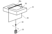
- a heat-fusible resin layer is heat-sealed by applying high temperature and high pressure to an electric storage device exterior material using a metal plate or the like.
- the heat-fusible resin layer located on the surface is crushed, and insulation of the exterior material for an electricity storage device is insulated. It was found that the sex is reduced.
- the present invention provides a heat-fusible resin in an exterior material for an electricity storage device, which is composed of a laminate including at least a base material layer, a barrier layer, and a heat-fusible resin layer in this order.
- a main object of the present invention is to provide a packaging material for an electricity storage device in which crushing when heat-sealing layers is effectively suppressed.
- a base material layer, a barrier layer, and a heat-fusible resin layer is composed of a laminate provided in this order, the heat-fusible resin layer is composed of a single layer or multiple layers.
- the logarithmic decrement ⁇ E at 140 ° C. in the rigid pendulum measurement of the first heat-fusible resin layer forming the surface of the laminate of the heat-fusible resin layers is 0.20 or less. It has been found that the device exterior material effectively suppresses crushing when the heat-fusible resin layer is heat-sealed.
- At least a base material layer, a barrier layer, and a heat-fusible resin layer which is composed of a laminate provided in this order
- the heat-fusible resin layer is composed of a single layer or multiple layers
- the first heat-fusible resin layer forming the surface of the laminate has a logarithmic decrement ⁇ E at 140 ° C. in a rigid body pendulum measurement of 0.20 or less.
- the heat-fusible resin layer is heat-melted in the exterior material for an electricity storage device, which is formed of a laminate including a base material layer, a barrier layer, and a heat-fusible resin layer in this order. It is possible to provide an exterior material for an electricity storage device in which crushing when attached is effectively suppressed. By suppressing the crushing, it is expected that the insulating property is improved, for example. Further, according to the present disclosure, it is also possible to provide a method for manufacturing an exterior material for an electricity storage device and an electricity storage device.
- FIG. 3 is a schematic diagram showing an example of a cross-sectional structure of a power storage device exterior material of the present disclosure.
- FIG. 3 is a schematic diagram showing an example of a cross-sectional structure of a power storage device exterior material of the present disclosure.
- FIG. 3 is a schematic diagram showing an example of a cross-sectional structure of a power storage device exterior material of the present disclosure.
- FIG. 3 is a schematic diagram showing an example of a cross-sectional structure of a power storage device exterior material of the present disclosure.
- FIG. 3 is a schematic diagram showing an example of a cross-sectional structure of a power storage device exterior material of the present disclosure.
- 2 is a micrograph of a cross section of a heat-sealing portion between heat-sealing resin layers of the exterior material for an electricity storage device obtained in Example 1 (taken at a magnification of 20 times).
- 3 is a micrograph of a cross section of a heat-sealing portion between heat-sealing resin layers of the exterior material for an electricity storage device obtained in Example 2 (taken at a magnification of 20 times).
- FIG. 4 is a micrograph of a cross section of a heat-sealing portion between heat-sealing resin layers of the exterior material for an electricity storage device obtained in Comparative Example 1 (taken at a magnification of 20 times).
- 7 is a micrograph of a cross section of a heat-sealing portion between heat-sealing resin layers of the exterior material for an electricity storage device obtained in Comparative Example 2 (taken at a magnification of 20 times). It is a schematic diagram for demonstrating the protrusion part formed inside the heat-fusion part of the heat-fusion resin layer.
- the electricity storage device exterior material of the present disclosure is composed of a laminate including at least a base material layer, a barrier layer, and a heat-fusible resin layer in this order, and the heat-fusible resin layer is a single layer.
- the first heat-fusible resin layer which is composed of a plurality of layers and constitutes the surface of the laminated body among the heat-fusible resin layers, has a logarithmic attenuation rate ⁇ E at 140 ° C. in the rigid pendulum measurement. It is characterized by being 0.20 or less. According to the exterior material for an electricity storage device of the present disclosure, the crushing at the time of heat-sealing the heat-fusible resin layer is effectively suppressed by having the configuration.
- the exterior material for the electricity storage device of the present disclosure will be described in detail.
- the numerical range indicated by “to” means “greater than or equal to” and “less than or equal to”.
- the expression 2 to 15 mm means 2 mm or more and 15 mm or less.
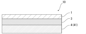
- An exterior material 10 for an electric storage device includes at least a base material layer 1, a barrier layer 3, and a heat-fusible resin layer 4, as shown in FIGS. 1 to 5. It is composed of a laminated body provided in this order.
- the base material layer 1 is the outermost layer side and the heat-fusible resin layer 4 is the inner layer side.
- the heat-fusible resin layer 4 is configured by a single layer or a plurality of layers, and among the heat-fusible resin layers 4, the first heat-fusible resin layer 41. Form the surface of the laminate.
- the heat-fusible resin layer 4 is composed of a single layer of the first heat-fusible resin layer 41, and the first heat-fusible resin layer 41 covers the surface of the laminate.
- the illustrated stacking arrangement is illustrated.
- the heat-fusible resin layer 4 is composed of a plurality of layers (two layers) of a first heat-fusible resin layer 41 and a second heat-fusible resin layer 42,
- the 1st heat-fusible resin layer 41 has illustrated the laminated structure which comprises the surface of the laminated body.
- the heat-fusible resin layer 4 further includes a third heat-fusible resin layer and a fourth heat-fusible resin layer.
- Another heat-fusible resin layer such as a heat-fusible resin layer may be provided on the barrier layer 3 side of the second heat-fusible resin layer 42.
- the peripheral edges are heat-sealed with the first heat-fusible resin layers 41 of the electricity storage device exterior material 10 facing each other.
- the electricity storage device element is housed in the space formed by the above.
- the exterior material 10 for an electricity storage device is provided between the base material layer 1 and the barrier layer 3 for the purpose of enhancing the adhesiveness between these layers and the like, if necessary.
- the adhesive layer 2 may be included.
- FIGS. 2, 4 and 5 between the barrier layer 3 and the heat-fusible resin layer 4, if necessary, for the purpose of enhancing the adhesiveness between these layers, etc.
- the adhesive layer 5 may be included.
- a surface coating layer 6 and the like may be provided on the outer side of the base material layer 1 (on the side opposite to the heat-fusible resin layer 4 side), if necessary.
- the thickness of the laminate constituting the exterior material 10 for an electricity storage device is not particularly limited, but from the viewpoint of cost reduction, energy density improvement, etc., preferably about 180 ⁇ m or less, about 155 ⁇ m or less. From the viewpoint of maintaining the function of the outer covering material for an electricity storage device of protecting, it is preferably about 35 ⁇ m or more, about 45 ⁇ m or more, about 60 ⁇ m or more, and the preferable range is, for example, about 35 to 180 ⁇ m, about 35 to 155 ⁇ m. , About 45 to 180 ⁇ m, about 45 to 155 ⁇ m, about 60 to 180 ⁇ m, about 60 to 155 ⁇ m.
- each layer forming the exterior material for a power storage device [base material layer 1]
- the base material layer 1 is a layer provided for the purpose of exerting a function as a base material of the exterior material for an electricity storage device.
- the base material layer 1 is located on the outer layer side of the exterior material for an electricity storage device.
- the material forming the base material layer 1 is not particularly limited as long as it has a function as a base material, that is, at least an insulating property.
- the base material layer 1 can be formed by using, for example, a resin, and the resin may contain an additive described below.
- the base material layer 1 may be, for example, a resin film made of resin, or may be formed by applying resin.
- the resin film may be an unstretched film or a stretched film.
- the stretched film include a uniaxially stretched film and a biaxially stretched film, and a biaxially stretched film is preferable.
- the stretching method for forming the biaxially stretched film include a sequential biaxial stretching method, an inflation method and a simultaneous biaxial stretching method.
- the method for applying the resin include a roll coating method, a gravure coating method and an extrusion coating method.
- Examples of the resin forming the base material layer 1 include resins such as polyester, polyamide, polyolefin, epoxy resin, acrylic resin, fluororesin, polyurethane, silicon resin, and phenol resin, and modified products of these resins.
- the resin forming the base material layer 1 may be a copolymer of these resins or a modified product of the copolymer. Further, it may be a mixture of these resins.
- the resin forming the base material layer 1 is preferably polyester or polyamide.
- polyester examples include polyethylene terephthalate, polybutylene terephthalate, polyethylene naphthalate, polybutylene naphthalate, polyethylene isophthalate, and copolyester.
- copolyester examples include a copolyester having ethylene terephthalate as a main repeating unit.
- a copolymer polyester which is mainly composed of ethylene terephthalate as a repeating unit and is polymerized with ethylene isophthalate (hereinafter abbreviated to polyethylene (terephthalate / isophthalate)), polyethylene (terephthalate / adipate), polyethylene (terephthalate / Sodium sulfoisophthalate), polyethylene (terephthalate / sodium isophthalate), polyethylene (terephthalate / phenyl-dicarboxylate), polyethylene (terephthalate / decanedicarboxylate) and the like.
- These polyesters may be used alone or in combination of two or more.
- polyamides include aliphatic polyamides such as nylon 6, nylon 66, nylon 610, nylon 12, nylon 46, and copolymers of nylon 6 and nylon 66; terephthalic acid and / or isophthalic acid.
- Hexamethylenediamine-isophthalic acid-terephthalic acid copolyamides such as nylon 6I, nylon 6T, nylon 6IT, nylon 6I6T (I represents isophthalic acid, T represents terephthalic acid) containing the derived constitutional unit, polyamide MXD6 (polymeta Polyamides containing aromatic compounds such as silylene adipamide; alicyclic polyamides such as polyamide PACM6 (polybis (4-aminocyclohexyl) methane adipamide); further lactam components and isocyanate components such as 4,4′-diphenylmethane-diisocyanate Polyamides obtained by copolymerizing, copolymerized polyamide and polyester or polyalkylene polyester amide cop
- the base material layer 1 preferably contains at least one of a polyester film, a polyamide film, and a polyolefin film, and preferably contains at least one of a stretched polyester film, a stretched polyamide film, and a stretched polyolefin film, It is more preferable to include at least one of a stretched polyethylene terephthalate film, a stretched polybutylene terephthalate film, a stretched nylon film, and a stretched polypropylene film.
- the base material layer 1 may be a single layer or may be composed of two or more layers.
- the base material layer 1 may be a laminate in which resin films are laminated with an adhesive or the like, or a resin is coextruded into two or more layers. It may be a laminate of the above resin films. Further, a resin film laminate obtained by coextruding a resin into two or more layers may be the unstretched base material layer 1 or may be uniaxially or biaxially stretched to form the base material layer 1.
- a laminate of two or more resin films in the base material layer 1 include a laminate of a polyester film and a nylon film, a laminate of two or more nylon films, a laminate of two or more polyester films. And the like, and preferably a laminate of a stretched nylon film and a stretched polyester film, a laminate of two or more stretched nylon films, and a laminate of two or more stretched polyester films.
- the base material layer 1 is a laminate of two resin films, a laminate of a polyester resin film and a polyester resin film, a laminate of a polyamide resin film and a polyamide resin film, or a polyester resin film and a polyamide resin film.
- a laminated body is preferable, and a laminated body of a polyethylene terephthalate film and a polyethylene terephthalate film, a laminated body of a nylon film and a nylon film, or a laminated body of a polyethylene terephthalate film and a nylon film is more preferable.
- the polyester resin does not easily discolor when an electrolytic solution adheres to the surface, when the base material layer 1 is a laminate of two or more resin films, the polyester resin film is It is preferably located in the outermost layer.
- the two or more resin films may be laminated via an adhesive.
- preferable adhesives include the same adhesives as those exemplified for the adhesive layer 2 described later.
- the method for laminating the two or more resin films is not particularly limited, and known methods can be adopted, and examples thereof include a dry laminating method, a sandwich laminating method, an extrusion laminating method, and a thermal laminating method, and preferably a dry laminating method.
- a laminating method can be mentioned.
- laminating by a dry laminating method it is preferable to use a polyurethane adhesive as the adhesive. At this time, the thickness of the adhesive is, for example, about 2 to 5 ⁇ m.
- an anchor coat layer may be formed on the resin film and laminated.
- the anchor coat layer may be the same as the adhesive exemplified in the adhesive layer 2 described later.
- the thickness of the anchor coat layer is, for example, about 0.01 to 1.0 ⁇ m.
- additives such as a lubricant, a flame retardant, an antiblocking agent, an antioxidant, a light stabilizer, a tackifier, and an antistatic agent are present on at least one of the surface and the inside of the base material layer 1. Good.
- the additive only one kind may be used, or two or more kinds may be mixed and used.
- a lubricant is preferably present on the surface of the base material layer 1 from the viewpoint of enhancing the moldability of the exterior material for an electricity storage device.
- the lubricant is not particularly limited, but preferably an amide lubricant is used.
- Specific examples of the amide-based lubricant include saturated fatty acid amides, unsaturated fatty acid amides, substituted amides, methylol amides, saturated fatty acid bisamides, unsaturated fatty acid bisamides, fatty acid ester amides, aromatic bisamides, and the like.
- saturated fatty acid amide examples include lauric acid amide, palmitic acid amide, stearic acid amide, behenic acid amide, and hydroxystearic acid amide.
- unsaturated fatty acid amides include oleic acid amide and erucic acid amide.
- substituted amide examples include N-oleylpalmitic acid amide, N-stearyl stearic acid amide, N-stearyl oleic acid amide, N-oleyl stearic acid amide, and N-stearyl erucic acid amide.
- methylolamide examples include methylolstearic acid amide.
- saturated fatty acid bisamide examples include methylenebisstearic acid amide, ethylenebiscapric acid amide, ethylenebislauric acid amide, ethylenebisstearic acid amide, ethylenebishydroxystearic acid amide, ethylenebisbehenic acid amide, and hexamethylenebisstearic acid amide.
- saturated fatty acid bisamide examples include acid amide, hexamethylene bisbehenic acid amide, hexamethylene hydroxystearic acid amide, N, N′-distearyl adipic acid amide and N, N′-distearyl sebacic acid amide.
- the unsaturated fatty acid bisamide include ethylene bisoleic acid amide, ethylene bis erucic acid amide, hexamethylene bis oleic acid amide, N, N'-dioleyl adipate amide, N, N'-dioleyl sebacic acid amide. And so on.
- Specific examples of the fatty acid ester amide include stearoamide ethyl stearate.
- specific examples of the aromatic bisamide include m-xylylenebisstearic acid amide, m-xylylenebishydroxystearic acid amide, N, N'-distearylisophthalic acid amide and the like.
- the lubricant may be used alone or in combination of two or more.
- the lubricant When the lubricant is present on the surface of the base material layer 1, its amount is not particularly limited, but is preferably about 3 mg / m 2 or more, more preferably about 4 to 15 mg / m 2 , and further preferably 5 to 14 mg. / M 2 is included.
- the lubricant present on the surface of the base material layer 1 may be one in which the lubricant contained in the resin forming the base material layer 1 is exuded, or the one coated with the lubricant on the surface of the base material layer 1. May be.
- the thickness of the base material layer 1 is not particularly limited as long as it can function as a base material, but is, for example, about 3 to 50 ⁇ m, preferably about 10 to 35 ⁇ m.
- the thickness of the resin film forming each layer is, for example, 2 to 35 ⁇ m, preferably about 2 to 25 ⁇ m.
- the adhesive layer 2 is a layer provided between the base material layer 1 and the barrier layer 3 as needed for the purpose of enhancing the adhesiveness.
- the adhesive layer 2 is formed of an adhesive that can bond the base material layer 1 and the barrier layer 3 together.
- the adhesive used for forming the adhesive layer 2 is not limited, and may be any of a chemical reaction type, a solvent volatilization type, a heat melting type, a heat pressure type and the like. Further, it may be a two-component curing type adhesive (two-component adhesive), a one-component curing type adhesive (one-component adhesive), or a resin that does not undergo a curing reaction.
- the adhesive layer 2 may be a single layer or a multilayer.
- the adhesive component contained in the adhesive include polyethylene terephthalate, polybutylene terephthalate, polyethylene naphthalate, polybutylene naphthalate, polyethylene isophthalate, polyesters such as copolyester; polyether; polyurethane; epoxy resin; Phenol resin; nylon 6, nylon 66, nylon 12, polyamide such as copolyamide; polyolefin resin such as polyolefin, cyclic polyolefin, acid modified polyolefin, acid modified cyclic polyolefin; polyvinyl acetate; cellulose; (meth) acrylic resin; Polyimide; Polycarbonate; Amino resin such as urea resin and melamine resin; Rubber such as chloroprene rubber, nitrile rubber and styrene-butadiene rubber; Silicone resin, etc.
- adhesive components may be used alone or in combination of two or more.
- a polyurethane adhesive is preferable.
- the resin serving as the adhesive component may be used in combination with an appropriate curing agent to enhance the adhesive strength.
- the curing agent is selected from polyisocyanates, polyfunctional epoxy resins, oxazoline group-containing polymers, polyamine resins, acid anhydrides, etc. depending on the functional groups of the adhesive component.
- the polyurethane adhesive examples include a polyurethane adhesive containing a base compound containing a polyol compound and a curing agent containing an isocyanate compound.
- a polyurethane adhesive containing a base compound containing a polyol compound and a curing agent containing an isocyanate compound.
- a two-component curing type polyurethane adhesive containing a polyol such as a polyester polyol, a polyether polyol and an acrylic polyol as a main component and an aromatic or aliphatic polyisocyanate as a curing agent.
- the polyol compound it is preferable to use a polyester polyol having a hydroxyl group at the side chain in addition to the hydroxyl group at the terminal of the repeating unit. Since the adhesive layer 2 is made of a polyurethane adhesive, excellent resistance to the electrolytic solution is imparted to the exterior material for an electricity storage device, and the base layer 1 is prevented from peeling off even when the electrolytic solution adhere
- the adhesive layer 2 may contain other components as long as it does not impair the adhesiveness, and may contain a colorant, a thermoplastic elastomer, a tackifier, a filler, or the like. Since the adhesive layer 2 contains the coloring agent, the exterior material for the electricity storage device can be colored. Known colorants such as pigments and dyes can be used as the colorant. Moreover, only one type of colorant may be used, or two or more types may be mixed and used.
- the type of pigment is not particularly limited as long as it does not impair the adhesiveness of the adhesive layer 2.
- the organic pigment include azo-based, phthalocyanine-based, quinacridone-based, anthraquinone-based, dioxazine-based, indigothioindigo-based, perinone-perylene-based, isoindolenin-based, benzimidazolone-based pigments, etc.
- the pigment include carbon black-based pigments, titanium oxide-based pigments, cadmium-based pigments, lead-based pigments, chromium oxide-based pigments, iron-based pigments, and other fine particles of mica (mica) and fish scale foil.
- colorants for example, carbon black is preferable in order to make the exterior material of the electricity storage device have a black appearance.
- the average particle diameter of the pigment is not particularly limited and may be, for example, about 0.05 to 5 ⁇ m, preferably about 0.08 to 2 ⁇ m.
- the average particle size of the pigment is the median size measured by a laser diffraction / scattering particle size distribution measuring device.
- the content of the pigment in the adhesive layer 2 is not particularly limited as long as the exterior material for the electricity storage device is colored, and is, for example, about 5 to 60% by mass, preferably 10 to 40% by mass.
- the thickness of the adhesive layer 2 is not particularly limited as long as the base material layer 1 and the barrier layer 3 can be adhered, but examples thereof include about 1 ⁇ m or more and about 2 ⁇ m or more, and about 10 ⁇ m or less and about 5 ⁇ m or less.
- the preferable range is about 1 to 10 ⁇ m, about 1 to 5 ⁇ m, about 2 to 10 ⁇ m, about 2 to 5 ⁇ m.
- the colored layer is a layer provided between the base material layer 1 and the barrier layer 3 as needed (not shown).
- a coloring layer may be provided between the base material layer 1 and the adhesive layer 2 and between the adhesive layer 2 and the barrier layer 3. Further, a colored layer may be provided outside the base material layer 1. By providing the colored layer, the exterior material for the electricity storage device can be colored.
- the coloring layer can be formed, for example, by applying an ink containing a coloring agent to the surface of the base material layer 1, the surface of the adhesive layer 2, or the surface of the barrier layer 3.
- a coloring agent such as pigments and dyes can be used as the colorant.
- only one type of colorant may be used, or two or more types may be mixed and used.
- coloring agent contained in the coloring layer are the same as those described in the section of [Adhesive layer 2].
- the barrier layer 3 is a layer that suppresses at least entry of moisture.
- the barrier layer 3 examples include a metal foil having a barrier property, a vapor deposition film, a resin layer, and the like.
- the vapor deposition film examples include a metal vapor deposition film, an inorganic oxide vapor deposition film, a carbon-containing inorganic oxide vapor deposition film, and the like
- the resin layer includes polyvinylidene chloride, polymers containing chlorotrifluoroethylene (CTFE) as a main component or tetra
- CTFE chlorotrifluoroethylene
- TFE fluoroethylene
- fluorine-containing resins such as polymers having a fluoroalkyl unit as a main component
- ethylene vinyl alcohol copolymers examples include ethylene vinyl alcohol copolymers.
- barrier layer 3 a resin film provided with at least one of the vapor deposition film and the resin layer may be used.
- a plurality of barrier layers 3 may be provided.
- the barrier layer 3 preferably includes a layer made of a metal material. Specific examples of the metal material forming the barrier layer 3 include aluminum alloys, stainless steels, titanium steels, and steel plates. When used as metal foils, at least one of aluminum alloy foils and stainless steel foils is included. It is preferable.
- the aluminum alloy foil is, from the viewpoint of improving the formability of the exterior material for an electricity storage device, for example, more preferably a soft aluminum alloy foil composed of an annealed aluminum alloy or the like, and from the viewpoint of further improving the formability. Therefore, the aluminum alloy foil containing iron is preferable.
- the content of iron is preferably 0.1 to 9.0 mass%, and more preferably 0.5 to 2.0 mass%. When the content of iron is 0.1% by mass or more, it is possible to obtain the exterior material for an electricity storage device having more excellent moldability. When the content of iron is 9.0% by mass or less, a more flexible outer packaging material for an electricity storage device can be obtained.
- the soft aluminum alloy foil for example, an aluminum alloy having a composition specified by JIS H4160: 1994 A8021H-O, JIS H4160: 1994 A8079H-O, JIS H4000: 2014 A8021P-O, or JIS H4000: 2014 A8079P-O.
- Foil can be mentioned. If necessary, silicon, magnesium, copper, manganese, etc. may be added.
- the softening can be performed by annealing treatment or the like.
- examples of stainless steel foils include austenite-based, ferrite-based, austenite-ferrite-based, martensite-based, and precipitation-hardening-based stainless steel foils. Further, from the viewpoint of providing an exterior material for an electricity storage device having excellent moldability, the stainless steel foil is preferably made of austenitic stainless steel.
- austenitic stainless steel forming the stainless steel foil examples include SUS304, SUS301, and SUS316L, and among these, SUS304 is particularly preferable.
- the thickness of the barrier layer 3 may be at least a function as a barrier layer that suppresses the infiltration of moisture, and is, for example, about 9 to 200 ⁇ m.
- the thickness of the barrier layer 3 is, for example, preferably about 85 ⁇ m or less, more preferably about 50 ⁇ m or less, further preferably about 40 ⁇ m or less, particularly preferably about 35 ⁇ m or less, and preferably about 10 ⁇ m or more, more preferably
- the thickness may be about 20 ⁇ m or more, more preferably about 25 ⁇ m or more.
- the preferable range of the thickness is about 10 to 85 ⁇ m, about 10 to 50 ⁇ m, about 10 to 40 ⁇ m, about 10 to 35 ⁇ m, about 20 to 85 ⁇ m, 20 to 50 ⁇ m.
- the barrier layer 3 is composed of an aluminum alloy foil, the above range is particularly preferable.
- the thickness of the stainless steel foil is preferably about 60 ⁇ m or less, more preferably about 50 ⁇ m or less, further preferably about 40 ⁇ m or less, and further preferably about 30 ⁇ m or less, particularly preferably about 25 ⁇ m or less, preferably about 10 ⁇ m or more, more preferably about 15 ⁇ m or more, and a preferable thickness range is about 10 to 60 ⁇ m, about 10 to 50 ⁇ m, about 10 to For example, about 40 ⁇ m, about 10 to 30 ⁇ m, about 10 to 25 ⁇ m, about 15 to 60 ⁇ m, about 15 to 50 ⁇ m, about 15 to 40 ⁇ m, about 15 to 30 ⁇ m, about 15 to 25 ⁇ m.
- the barrier layer 3 when the barrier layer 3 is a metal foil, it is preferable to provide a corrosion resistant film on at least the surface opposite to the base material layer in order to prevent dissolution and corrosion.
- the barrier layer 3 may have a corrosion resistant coating on both sides.
- the corrosion-resistant film means, for example, hot water conversion treatment such as boehmite treatment, chemical conversion treatment, anodization treatment, plating treatment with nickel or chromium, and corrosion prevention treatment for coating a coating agent on the surface of the barrier layer.
- a barrier layer having corrosion resistance for example, acid resistance, alkali resistance, etc.
- the corrosion-resistant coating specifically means a coating that improves the acid resistance of the barrier layer (acid-resistant coating), a coating that improves the alkali resistance of the barrier layer (alkali-resistant coating), and the like.
- the treatment for forming the corrosion resistant film one type may be performed, or two or more types may be combined and performed. Further, not only one layer but also multiple layers can be formed. Further, among these treatments, the hydrothermal conversion treatment and the anodizing treatment are treatments for dissolving the surface of the metal foil with a treatment agent to form a metal compound having excellent corrosion resistance. Note that these processes may be included in the definition of the chemical conversion process.
- the barrier layer 3 when the barrier layer 3 has a corrosion resistant film, the barrier layer 3 includes the corrosion resistant film.
- the corrosion-resistant coating is used to prevent delamination between the barrier layer (for example, aluminum alloy foil) and the base material layer during the molding of the exterior material for the electricity storage device, and to prevent hydrogen fluoride generated by the reaction between the electrolyte and water.
- the barrier layer for example, aluminum alloy foil
- Dissolution and corrosion of the surface of the barrier layer especially when the barrier layer is an aluminum alloy foil, prevents the aluminum oxide present on the surface of the barrier layer from dissolving and corroding, and the adhesiveness (wettability) of the surface of the barrier layer
- the effect of preventing delamination between the base material layer and the barrier layer during heat sealing, and preventing delamination between the base material layer and the barrier layer during molding are examples of the barrier layer and the base material layer during heat sealing.
- Various types of corrosion-resistant films formed by chemical conversion treatment are known, and are mainly at least one of phosphates, chromates, fluorides, triazine thiol compounds, and rare earth oxides. And a corrosion resistant film containing the like.
- Examples of the chemical conversion treatment using a phosphate or chromate include chromate chromate treatment, chromate phosphoric acid treatment, phosphoric acid-chromate treatment, chromate treatment, and the like.
- Examples of the compound include chromium nitrate, chromium fluoride, chromium sulfate, chromium acetate, chromium oxalate, chromium diphosphate, acetyl acetate chromate, chromium chloride, potassium chromium sulfate and the like.
- examples of the phosphorus compound used for these treatments include sodium phosphate, potassium phosphate, ammonium phosphate, polyphosphoric acid, and the like.
- examples of the chromate treatment include etching chromate treatment, electrolytic chromate treatment, coating type chromate treatment and the like, and coating type chromate treatment is preferable.
- the inner layer side of the barrier layer eg, aluminum alloy foil
- a well-known method such as an alkali dipping method, an electrolytic cleaning method, an acid cleaning method, an electrolytic acid cleaning method, and an acid activation method.
- a degreasing treatment is performed by a treatment method, and thereafter, a phosphate metal such as Cr (chromium) phosphate, Ti (titanium) phosphate, Zr (zirconium) phosphate, Zn (zinc) phosphate, etc.
- a treatment liquid such as water, alcohol solvents, hydrocarbon solvents, ketone solvents, ester solvents, ether solvents can be used, and water is preferable.
- Examples of the resin component used at this time include polymers such as phenol resins and acrylic resins, and aminated phenol polymers having repeating units represented by the following general formulas (1) to (4) are used. Examples include the chromate treatment used. In the aminated phenol polymer, the repeating units represented by the following general formulas (1) to (4) may be contained alone or in any combination of two or more. Good.
- Acrylic resin must be polyacrylic acid, acrylic acid methacrylic acid ester copolymer, acrylic acid maleic acid copolymer, acrylic acid styrene copolymer, or their derivatives such as sodium salt, ammonium salt, amine salt, etc. Is preferred.
- polyacrylic acid derivatives such as ammonium salt, sodium salt, or amine salt of polyacrylic acid.
- polyacrylic acid means a polymer of acrylic acid.
- the acrylic resin is also preferably a copolymer of acrylic acid and a dicarboxylic acid or a dicarboxylic acid anhydride, an ammonium salt of a copolymer of acrylic acid and a dicarboxylic acid or a dicarboxylic acid anhydride, a sodium salt, Alternatively, it is also preferably an amine salt. Only one type of acrylic resin may be used, or two or more types may be mixed and used.
- X represents a hydrogen atom, a hydroxy group, an alkyl group, a hydroxyalkyl group, an allyl group or a benzyl group.
- R 1 and R 2 are the same or different and each represents a hydroxy group, an alkyl group, or a hydroxyalkyl group.
- examples of the alkyl group represented by X, R 1 and R 2 include a methyl group, an ethyl group, an n-propyl group, an isopropyl group, an n-butyl group, an isobutyl group, Examples thereof include linear or branched alkyl groups having 1 to 4 carbon atoms such as tert-butyl group.
- examples of the hydroxyalkyl group represented by X, R 1 and R 2 include, for example, hydroxymethyl group, 1-hydroxyethyl group, 2-hydroxyethyl group, 1-hydroxypropyl group, 2-hydroxypropyl group and 3-hydroxypropyl group.
- An alkyl group is mentioned.
- the alkyl group and the hydroxyalkyl group represented by X, R 1 and R 2 may be the same or different.
- X is preferably a hydrogen atom, a hydroxy group or a hydroxyalkyl group.
- the number average molecular weight of the aminated phenol polymer having the repeating units represented by the general formulas (1) to (4) is, for example, preferably about 500 to 1,000,000, and more preferably about 1,000 to 20,000. More preferable.
- the aminated phenol polymer is produced by, for example, polycondensing a phenol compound or a naphthol compound with formaldehyde to produce a polymer having a repeating unit represented by the general formula (1) or (3), and then formaldehyde. And an amine (R 1 R 2 NH) to introduce a functional group (—CH 2 NR 1 R 2 ) into the polymer obtained above.
- the aminated phenol polymer is used alone or in combination of two or more.
- the corrosion resistant film is formed by a coating type corrosion prevention treatment in which a coating agent containing at least one selected from the group consisting of rare earth element oxide sols, anionic polymers and cationic polymers is applied.
- a thin film is used.
- the coating agent may further contain phosphoric acid or phosphate, and a cross-linking agent that cross-links the polymer.
- fine particles of rare earth element oxide for example, particles having an average particle diameter of 100 nm or less
- the rare earth element oxide include cerium oxide, yttrium oxide, neodymium oxide, and lanthanum oxide, and cerium oxide is preferable from the viewpoint of further improving the adhesiveness.
- the rare earth element oxides contained in the corrosion resistant coating may be used alone or in combination of two or more.
- various solvents such as water, alcohol solvents, hydrocarbon solvents, ketone solvents, ester solvents, ether solvents can be used, and water is preferable.
- the cationic polymer include polyethyleneimine, an ionic polymer complex composed of a polymer having polyethyleneimine and a carboxylic acid, a primary amine-grafted acrylic resin obtained by graft-polymerizing a primary amine on an acrylic main skeleton, polyallylamine or a derivative thereof. , Aminated phenol and the like are preferable.
- the anionic polymer is preferably poly (meth) acrylic acid or a salt thereof, or a copolymer containing (meth) acrylic acid or a salt thereof as a main component.
- the cross-linking agent is at least one selected from the group consisting of a compound having any one of an isocyanate group, a glycidyl group, a carboxyl group and an oxazoline group, and a silane coupling agent.
- the phosphoric acid or phosphate is preferably condensed phosphoric acid or condensed phosphate.
- a dispersion of fine particles of metal oxide such as aluminum oxide, titanium oxide, cerium oxide, and tin oxide or barium sulfate in phosphoric acid is applied to the surface of the barrier layer, Examples include those formed by performing a baking treatment at a temperature of not less than ° C.
- the corrosion-resistant film may have a laminated structure in which at least one of a cationic polymer and an anionic polymer is further laminated, if necessary.
- a cationic polymer and an anionic polymer include those mentioned above.
- composition of the corrosion resistant film can be performed using, for example, time-of-flight secondary ion mass spectrometry.
- the amount of the corrosion resistant film formed on the surface of the barrier layer 3 in the chemical conversion treatment is not particularly limited, but, for example, when the coating type chromate treatment is performed, the chromic acid compound per 1 m 2 of the surface of the barrier layer 3 is used.
- the chromic acid compound per 1 m 2 of the surface of the barrier layer 3 is used.
- the phosphorus compound is, for example, about 0.5 to 50 mg, preferably about 1.0 to 40 mg in terms of phosphorus, and aminated phenol polymer.
- the thickness of the corrosion-resistant film is not particularly limited, but from the viewpoint of the cohesive force of the film and the adhesion with the barrier layer or the heat-fusible resin layer, it is preferably about 1 nm to 20 ⁇ m, more preferably 1 nm to 100 nm. Degree, and more preferably about 1 nm to 50 nm.
- the thickness of the corrosion-resistant coating can be measured by observation with a transmission electron microscope or a combination of observation with a transmission electron microscope and energy dispersive X-ray spectroscopy or electron beam energy loss spectroscopy.
- composition of the corrosion-resistant coating using time-of-flight secondary ion mass spectrometry for example, at least one secondary ion consisting of Ce, P, and O (eg, Ce 2 PO 4 + , CePO 4 ⁇ , etc. Species) or, for example, a peak derived from a secondary ion of Cr, P, and O (for example, at least one of CrPO 2 + , CrPO 4 ⁇ ).
- the chemical conversion treatment is performed by applying a solution containing a compound used for forming a corrosion-resistant film to the surface of the barrier layer by a bar coating method, a roll coating method, a gravure coating method, a dipping method, or the like, and then applying the temperature of the barrier layer. Is heated to about 70 to 200 ° C.
- the barrier layer may be subjected to a degreasing treatment by an alkali dipping method, an electrolytic cleaning method, an acid cleaning method, an electrolytic acid cleaning method, or the like before the barrier layer is subjected to the chemical conversion treatment. By performing the degreasing treatment in this way, the chemical conversion treatment of the surface of the barrier layer can be performed more efficiently.
- the heat-fusible resin layer 4 In the exterior material for an electricity storage device of the present disclosure, the heat-fusible resin layer 4 is located on the inner layer side, and has a function of sealing the electricity storage device element by heat fusion of the heat-fusible resin layer during assembly of the electricity storage device. It is a layer (sealant layer) that exerts its effect.
- the heat-fusible resin layer 4 In the electricity storage device exterior material 10 of the present disclosure, the heat-fusible resin layer 4 is configured by a single layer or a plurality of layers, and among the heat-fusible resin layers 4, the first heat-fusible resin layer 41. Form the surface of the laminate. Therefore, when assembling the electricity storage device, the first heat-fusible resin layer 41 is heat-sealed to seal the electricity storage device element.
- the heat fusible resin layer 4 When the heat fusible resin layer 4 is composed of a single layer, the heat fusible resin layer 4 constitutes the first heat fusible resin layer 41. 1 and 2, the heat-fusible resin layer 4 is composed of a single layer of the first heat-fusible resin layer 41, and the first heat-fusible resin layer 41 covers the surface of the laminate. The illustrated stacking arrangement is illustrated.
- the heat-fusible resin layer 4 is composed of a plurality of layers, at least the first heat-fusible resin layer 41 and the second heat-bondable resin layer 41 are arranged in this order from the front surface side of the laminate forming the exterior material 10 for an electricity storage device.
- the heat-fusible resin layer 42 is provided.
- the heat-fusible resin layer 4 is composed of a plurality of layers (two layers) of a first heat-fusible resin layer 41 and a second heat-fusible resin layer 42.
- the heat-fusible resin layer 41 shows the laminated structure which comprises the surface of a laminated body.
- the heat-fusible resin layer 4 is composed of a plurality of layers, the heat-fusible resin layer 4 is further added to the first heat-fusible resin layer 41 and the second heat-fusible resin layer 42.
- a third heat-fusible resin layer, a fourth heat-fusible resin layer, etc. may be provided on the barrier layer 3 side of the second heat-fusible resin layer 42.
- the heat-fusible resin layer 4 is composed of multiple layers, the heat-fusible resin layer 4 is composed of two layers of a first heat-fusible resin layer 41 and a second heat-fusible resin layer 42. Is preferably provided.
- the exterior material for an electricity storage device is characterized in that the logarithmic decrement ⁇ E at 140 ° C. in the rigid pendulum measurement of the first heat-fusible resin layer 41 is 0.20 or less.
- the logarithmic attenuation rate ⁇ E at 140 ° C. is 0.20 or less, the crushing when the first heat-fusible resin layer 41 is heat-sealed is effectively suppressed.
- the logarithmic decrement at 140 ° C in the rigid pendulum measurement is an index showing the hardness of the resin in a high temperature environment of 140 ° C, and the smaller the logarithmic decrement, the higher the resin hardness.
- the temperature at which the heat-fusible resin layer is heat-fused is high, and the heat-fusible resin layer is heat-fused in the heat-fusing part formed by heat-fusing the heat-fusible resin layer. In some cases, it may largely protrude inside the portion (on the side of the space in which the electricity storage device element is accommodated).
- FIG. 11 shows a schematic cross-sectional view in which the protruding portion A is formed inside the heat-sealing portion of the heat-sealing resin layer 4.
- the projecting portion A has end points A1 and A2, and these end points A1 and A2 tend to be the origins of cracks in the structure.
- the insulating property is likely to decrease due to the crack. Therefore, it is important to control the shape of the heat-sealing portion, and for that purpose, the hardness of the heat-sealing resin layer at high temperature is important. Therefore, in the present invention, the logarithmic decay rate at a high temperature of 140 ° C. is adopted. In the rigid pendulum measurement, the damping rate of the pendulum when the temperature of the resin is raised from a low temperature to a high temperature is measured.
- the edge portion is brought into contact with the surface of the measurement target object, and the pendulum movement is performed in the left-right direction to impart vibration to the measurement target object.
- a hard first heat-fusible resin layer 41 having a logarithmic decrement of 0.20 or less in a high temperature environment of 140 ° C. is arranged on the surface of the exterior material for an electricity storage device. As a result, crushing (thinning) of the first heat-fusible resin layer 41 at the time of heat-sealing the exterior material for an electricity storage device is suppressed.
- the heat-fusible resin layer is a heat-fusible part in the heat-fusible portion formed by heat-sealing the heat-fusible resin layer.
- the large protrusion inside is suppressed, and the deterioration of the insulating property of the exterior material for an electricity storage device due to heat fusion is effectively suppressed.
- ⁇ E [ln (A1 / A2) + ln (A2 / A3) + ... ln (An / An + 1)] / n A: amplitude n: wave number
- the logarithmic decrement ⁇ E is preferably about 0.10 or more, more preferably about 0.11 or more, still more preferably about 0.12 or more, and preferably about 0.18 or less, more preferably.
- a preferable range is about 0.10 to 0.20, about 0.10 to 0.18, about 0.10 to 0.15, 0.10 to 0.13, 0.11 to 0.20, 0.11 to 0.18, 0.11 to 0.15, 0.11 to 0.13, 0.12 to 0 .20, 0.12 to 0.18, 0.12 to 0.15 About 0.12 to 0.13, and the like.
- the logarithmic decrement ⁇ E at 80 ° C. in the rigid pendulum measurement of the first heat-fusible resin layer 41 is preferably more than 0.08, more preferably about 0.09 or more. And more preferably about 0.10.
- the logarithmic decrement ⁇ E at 80 ° C. in the rigid pendulum measurement of the first heat-fusible resin layer 41 is preferably about 0.20 or less, more preferably about 0.
- the preferable range of the logarithmic decay rate ⁇ E is 0.08 to 0.20 or less, 0.08 to 0.18 or less, 0.08 to 0.15 or less, 0.09 to 0.20, 0. 0.09 to 0.18 degrees, 0.09 to 0.15 degrees, 0.10 to 0.20 degrees, 0.10 to 0.18 degrees, 0.10 to 0.15 degrees.
- the logarithmic decrement ⁇ E at 80 ° C. in the rigid pendulum measurement of the first heat-fusible resin layer 41 is the surface of the first heat-fusible resin layer 41 in the method for measuring the logarithmic decrement ⁇ E at 140 ° C.
- the measurement is performed in the same manner except that the logarithmic decrement ⁇ E at the temperature of 80 ° C. is adopted.
- the logarithmic decrement ⁇ E of the first heat-fusible resin layer 41 is, for example, the melt mass flow rate (MFR), molecular weight, melting point, softening point, molecular weight distribution of the resin forming the first heat-fusible resin layer 41. , And the degree of crystallinity can be adjusted.
- the sample in which the base material layer and the barrier layer were dissolved by immersing the exterior material for an electricity storage device in 15% hydrochloric acid was sufficiently dried.
- the exterior material for an electricity storage device includes an adhesive layer 5 described below, a laminate of the adhesive layer 5 and the heat-fusible resin layer 4 is used as a sample.
- the logarithmic attenuation rate ⁇ E of the first heat-fusible resin layer 41 can be measured by acquiring the exterior material for the electricity storage device from the electricity storage device.
- a sample is cut out from the top surface portion where the exterior material for the electricity storage device is not stretched by molding. To be measured.
- the heat-fusible resin layers of the laminate constituting the exterior material for an electricity storage device are opposed to each other, and the temperature is 190 ° C., the surface pressure is 2.0 MPa, and the time is 3 seconds.
- the remaining ratio of the total thickness of the two first heat-fusible resin layers 41 is preferably about 30% or more, and more preferably about 32% or more. It is preferably about 34% or more, and preferable ranges include 30 to 60%, 32 to 60%, 34 to 60%, 30 to 50%, 32 to 50%, 34 to 50%.
- the upper limit of the remaining ratio of the thickness is, for example, about 60% or 50%.
- the remaining ratio of the thickness is a value measured by the following method. In order to set the remaining ratio of the thickness, for example, the type, composition, molecular weight, etc. of the resin forming the first heat-fusible resin layer 41 are adjusted.
- a test sample is prepared by cutting the exterior material for an electricity storage device into a length of 150 mm and a width of 60 mm. Next, the first heat-fusible resin layers 41 of the test sample are opposed to each other. Then, in that state, using a metal plate with a width of 7 mm, the test sample was heated and pressed in the stacking direction from both sides in the conditions of a temperature of 190 ° C., a surface pressure of 0.5 MPa, and a time of 3 seconds. The fusible resin layer 41 is thermally fused.
- the heat-sealed portion of the test sample is cut in the stacking direction using a microtome, and the exposed cross-section is the total of the two first heat-meltable resin layers 41 heat-sealed to each other. Measure the thickness.
- the test sample before heat fusion is cut in the laminating direction using a microtome, and the thickness of the two first heat fusion resin layers 41 is measured for the exposed cross section.
- the ratio of the total thickness of the two first heat-fusible resin layers 41 after heat fusion to the total thickness of the two first heat-fusible resin layers 41 before heat fusion is calculated to be 2
- the residual ratio (%) of the total thickness of the two first heat-fusible resin layers 41 is measured.
- the thickness of the two first heat-fusible resin layers 41 in the heat-sealed portion is measured at a location where the thickness of the exterior material for an electricity storage device is constant.
- the exterior material for an electricity storage device from the electricity storage device and measure the remaining ratio of the total thickness of the two first heat-fusible resin layers 41.
- the top surface portion where the exterior material for the electricity storage device is not stretched by molding The sample is cut out from and used as the measurement target.
- the resin constituting the first heat-fusible resin layer 41 is heat-fusible, and the logarithmic decrement ⁇ E of the first heat-fusible resin layer 41 is 0.20 or less. It is not particularly limited to.
- the resin forming the first heat-fusible resin layer 41 is preferably a resin containing a polyolefin skeleton such as polyolefin or acid-modified polyolefin.
- the fact that the resin forming the first heat-fusible resin layer 41 contains a polyolefin skeleton can be analyzed by, for example, infrared spectroscopy, gas chromatography mass spectrometry, or the like.
- infrared spectroscopy gas chromatography mass spectrometry, or the like.
- a peak derived from maleic acid is detected in the vicinity of the wave number of 1760 cm -1 and near the wave number 1780 cm -1.
- the first heat-fusible resin layer 41 is a layer composed of a maleic anhydride-modified polyolefin
- a peak derived from maleic anhydride is detected when measured by infrared spectroscopy.
- the degree of acid modification is low, the peak may be too small to be detected. In that case, it can be analyzed by nuclear magnetic resonance spectroscopy.
- polystyrene resin examples include polyethylene such as low density polyethylene, medium density polyethylene, high density polyethylene, and linear low density polyethylene; ethylene- ⁇ olefin copolymers; homopolypropylene, block copolymers of polypropylene (for example, propylene and Examples thereof include polypropylene block copolymers) and polypropylene random copolymers (for example, random copolymers of propylene and ethylene); propylene- ⁇ -olefin copolymers; ethylene-butene-propylene terpolymers. Of these, polypropylene is preferred.
- the polyolefin resin is a copolymer, it may be a block copolymer or a random copolymer. These polyolefin resins may be used alone or in combination of two or more.
- the polyolefin may be a cyclic polyolefin.
- the cyclic polyolefin is a copolymer of an olefin and a cyclic monomer, and examples of the olefin constituting the cyclic polyolefin include ethylene, propylene, 4-methyl-1-pentene, styrene, butadiene and isoprene.
- the cyclic monomer which is a constituent monomer of the cyclic polyolefin include cyclic alkenes such as norbornene; cyclic dienes such as cyclopentadiene, dicyclopentadiene, cyclohexadiene and norbornadiene. Among these, cyclic alkenes are preferable, and norbornene is more preferable.
- Acid-modified polyolefin is a polymer modified by block or graft polymerization of polyolefin with an acid component.
- the acid-modified polyolefin the above-mentioned polyolefin, a copolymer obtained by copolymerizing the above-mentioned polyolefin with a polar molecule such as acrylic acid or methacrylic acid, or a polymer such as a cross-linked polyolefin can be used.
- the acid component used for acid modification include carboxylic acids such as maleic acid, acrylic acid, itaconic acid, crotonic acid, maleic anhydride, and itaconic anhydride, or anhydrides thereof.
- the acid-modified polyolefin may be an acid-modified cyclic polyolefin.
- the acid-modified cyclic polyolefin is a polymer obtained by copolymerizing some of the monomers constituting the cyclic polyolefin instead of the acid component, or by block-polymerizing or graft-polymerizing the acid component with respect to the cyclic polyolefin. is there.
- the acid-modified cyclic polyolefin is the same as described above.
- the acid component used for the acid modification is the same as the acid component used for the modification of the polyolefin.
- Preferred acid-modified polyolefins include polyolefins modified with carboxylic acids or their anhydrides, polypropylene modified with carboxylic acids or their anhydrides, maleic anhydride-modified polyolefins, maleic anhydride-modified polypropylenes.
- the first heat-fusible resin layer 41 may be formed of one type of resin alone, or may be formed of a blend polymer in which two or more types of resins are combined.
- the first heat-fusible resin layer 41 forming the surface preferably contains polyolefin.
- the heat-fusible resin layer 4 includes the first heat-fusible resin layer 41 and the second heat-fusible resin layer 42 in the exterior material 10 for an electricity storage device of the present disclosure, the surface is formed. It is preferable that the first heat-fusible resin layer 41 contains polyolefin and the second heat-fusible resin layer 42 contains acid-modified polyolefin.
- the adhesive layer 5 when the adhesive layer 5 is provided, the first heat-fusible resin layer 41 constituting the surface contains polyolefin, and the adhesive layer 5 is acid-modified. It preferably contains a polyolefin.
- the adhesive layer 5 contains an acid-modified polyolefin
- the first heat-fusible resin layer contains a polyolefin
- the second heat-fusible resin layer contains a polyolefin. More preferably, the first heat-fusible resin layer contains polypropylene, and the second heat-fusible resin layer contains polypropylene.
- the first heat-fusible resin layer 41 may contain a lubricant and the like, if necessary.
- a lubricant When the first heat-fusible resin layer 41 contains a lubricant, the moldability of the exterior material for an electricity storage device can be improved.
- the lubricant is not particularly limited, and known lubricants can be used.
- the lubricant may be used alone or in combination of two or more.
- the lubricant is not particularly limited, but an amide lubricant is preferable. Specific examples of the lubricant include those exemplified for the base material layer 1. The lubricant may be used alone or in combination of two or more.
- the amount of the lubricant is not particularly limited, but is preferably 10 to 50 mg / m from the viewpoint of enhancing the moldability of the exterior material for an electricity storage device. About 2 and more preferably about 15 to 40 mg / m 2 . Even when a lubricant is present on the surface of the first heat-fusible resin layer 41, the first heat-fusible resin layer 41, including the lubricant, constitutes the surface of the power storage device exterior material 10. To do.
- the lubricant present on the surface of the first heat-fusible resin layer 41 may be one in which the lubricant contained in the resin forming the first heat-fusible resin layer 41 is exuded, or the first heat-meltable resin
- the surface of the adhesive resin layer 41 may be coated with a lubricant.
- the thickness of the first heat-fusible resin layer 41 is not particularly limited as long as the heat-fusible resin layer has a function of heat-sealing and sealing the electricity storage device element.
- the thickness of the first heat-fusible resin layer 41 is preferably about 100 ⁇ m or less and about 85 ⁇ m or less. , About 60 ⁇ m or less, 5 ⁇ m or more, 10 ⁇ m or more, 20 ⁇ m or more, 30 ⁇ m or more, 40 ⁇ m or more, and a preferable range is about 5 to 100 ⁇ m, about 5 to 85 ⁇ m, about 5 to 60 ⁇ m, 10 to 100 ⁇ m, 10-85 ⁇ m, 10-60 ⁇ m, 20-100 ⁇ m, 20-85 ⁇ m, 20-60 ⁇ m, 30-100 ⁇ m, 30-85 ⁇ m, 30-60 ⁇ m, 40-100 ⁇ m, 40- The thickness is about 85 ⁇ m, about 40 to 60 ⁇ m.
- the heat-fusible resin layer 4 is the same as the first heat-fusible resin layer 41.
- the thickness of the first heat-fusible resin layer 41 is preferably about 100 ⁇ m or less, about 85 ⁇ m or less, about 60 ⁇ m or less, about 25 ⁇ m or less, and 5 ⁇ m or more and 10 ⁇ m.
- 20 ⁇ m or more, 30 ⁇ m or more, 40 ⁇ m or more can be mentioned, and a preferable range is about 5 to 100 ⁇ m, about 5 to 85 ⁇ m, about 5 to 60 ⁇ m, about 5 to 25 ⁇ m, about 10 to 100 ⁇ m, about 10 to 85 ⁇ m, 10 ⁇ 60 ⁇ m, 10-25 ⁇ m, 20-100 ⁇ m, 20-85 ⁇ m, 20-60 ⁇ m, 20-25 ⁇ m, 30-100 ⁇ m, 30-85 ⁇ m, 30-60 ⁇ m Time, approximately 40 ⁇ 100 [mu] m, about 40 ⁇ 85 .mu.m, include about 40 ⁇ 60 [mu] m.
- the heat-fusible resin layer 4 is the first.
- the thickness of the first heat-fusible resin layer 41 is preferably about 85 ⁇ m or less, about 60 ⁇ m or less, about 25 ⁇ m or less.
- 5 ⁇ m or more, 10 ⁇ m or more, 20 ⁇ m or more, 30 ⁇ m or more, 40 ⁇ m or more, and a preferable range is about 5 to 85 ⁇ m, about 5 to 60 ⁇ m, about 5 to 25 ⁇ m, about 10 to 85 ⁇ m, 10 ⁇ 60 ⁇ m, 10-25 ⁇ m, 20-85 ⁇ m, 20-60 ⁇ m, 20-25 ⁇ m, 30-85 ⁇ m, 30-60 ⁇ m, 40-85 ⁇ m, 40-60 ⁇ m .
- the resin forming the second heat-fusible resin layer 42 has a polyolefin skeleton such as polyolefin or acid-modified polyolefin. Resins containing are preferred. These resins are the same as the resins described for the first heat-fusible resin layer 41.
- the fact that the resin forming the second heat-fusible resin layer 42 contains a polyolefin skeleton can be analyzed by, for example, infrared spectroscopy, gas chromatography mass spectrometry, or the like.
- the resin forming the second heat-fusible resin layer 42 is analyzed by infrared spectroscopy, it is preferable that a peak derived from maleic anhydride is detected.
- a peak derived from maleic anhydride is detected in the vicinity of the wave number of 1760 cm -1 and near the wave number 1780 cm -1.
- the second heat-fusible resin layer 42 is a layer composed of maleic anhydride-modified polyolefin
- a peak derived from maleic anhydride is detected when measured by infrared spectroscopy.
- the degree of acid modification is low, the peak may be too small to be detected. In that case, it can be analyzed by nuclear magnetic resonance spectroscopy.
- the second heat-fusible resin layer 42 preferably contains polyolefin.
- the 2 heat-fusible resin layer 42 preferably contains a polyolefin.
- the exterior material 10 for an electricity storage device of the present disclosure in the case where the heat-fusible resin layer 4 includes the first heat-fusible resin layer 41 and the second heat-fusible resin layer 42.
- the first heat-fusible resin layer 41 forming the surface contains a polyolefin
- the second heat-fusible resin layer 42 is an acid-modified polyolefin. It is preferable to include.
- the thickness of the second heat-fusible resin layer 42 is not particularly limited as long as the heat-fusible resin layer 4 has a function of heat-sealing and sealing the electricity storage device element.
- the thickness of the second heat-fusible resin layer 42 is The thickness is preferably larger than the thickness of the first heat-fusible resin layer 41.
- a resin that easily flows at a high temperature is preferably used so that the heat-fusible property is excellent.
- the thickness of the second heat-fusible resin layer 42 is set as the thickness of the second heat-fusible resin layer 42 from the viewpoint of effectively suppressing the crushing when the first heat-fusible resin layer 41 is heat-sealed and improving the sealing performance of the power storage device exterior material. Is preferably about 100 ⁇ m or less, about 85 ⁇ m or less, about 60 ⁇ m or less, and 5 ⁇ m or more, 10 ⁇ m or more, 20 ⁇ m or more, 30 ⁇ m or more, 40 ⁇ m or more, and a preferable range is about 5 to 100 ⁇ m, 5 or less.
- the heat-fusible resin layer 4 includes, in addition to the first heat-fusible resin layer 41 and the second heat-fusible resin layer 42, a third heat-fusible resin layer and a fourth heat-fusible resin layer.
- Other heat-fusible resin layers such as the above may be provided on the barrier layer 3 side of the second heat-fusible resin layer 42.
- the resin forming the other heat-fusible resin layer the same resins as those described for the first heat-fusible resin layer 41 are exemplified.
- the thickness of each of the other heat-fusible resin layers is the same as the thickness described for the second heat-fusible resin layer 42.
- the total thickness of the heat-fusible resin layer 4 is preferably about 100 ⁇ m or less, about 85 ⁇ m or less, about 60 ⁇ m or less, and 5 ⁇ m or more, 10 ⁇ m or more, 20 ⁇ m or more, 30 ⁇ m or more, 40 ⁇ m or more,
- the preferred range is about 5 to 100 ⁇ m, about 5 to 85 ⁇ m, about 5 to 60 ⁇ m, about 10 to 100 ⁇ m, about 10 to 85 ⁇ m, about 10 to 60 ⁇ m, about 20 to 100 ⁇ m, about 20 to 85 ⁇ m, about 20 to 60 ⁇ m, Examples thereof include about 30 to 100 ⁇ m, about 30 to 85 ⁇ m, about 30 to 60 ⁇ m, about 40 to 100 ⁇ m, about 40 to 85 ⁇ m, and about 40 to 60 ⁇ m.
- the adhesive layer 5 is provided between the barrier layer 3 (or the corrosion resistant film) and the heat-fusible resin layer 4 as needed in order to firmly bond them. It is a layer.
- the adhesive layer 5 is formed of a resin that can bond the barrier layer 3 and the heat-fusible resin layer 4.
- the resin used for forming the adhesive layer 5 for example, the same resins as those exemplified for the adhesive layer 2 can be used.
- the resin used to form the adhesive layer 5 preferably contains a polyolefin skeleton, and examples thereof include the polyolefins and the acid-modified polyolefins described above as the first heat-fusible resin layer 41.
- the fact that the resin constituting the adhesive layer 5 contains a polyolefin skeleton can be analyzed by, for example, infrared spectroscopy, gas chromatography mass spectrometry, etc., and the analysis method is not particularly limited.
- the resin constituting the adhesive layer 5 is analyzed by infrared spectroscopy, it is preferable to detect a peak derived from maleic anhydride.
- a peak derived from maleic acid is detected in the vicinity of the wave number of 1760 cm -1 and near the wave number 1780 cm -1.
- the degree of acid modification is low, the peak may be too small to be detected. In that case, it can be analyzed by nuclear magnetic resonance spectroscopy.
- the adhesive layer 5 can be formed of a thermoplastic resin or a cured product of a thermosetting resin, and is preferably formed of a thermoplastic resin.
- the adhesive layer 5 preferably contains an acid-modified polyolefin.
- an acid-modified polyolefin a polyolefin modified with a carboxylic acid or an anhydride thereof, a polypropylene modified with a carboxylic acid or an anhydride thereof, a maleic anhydride modified polyolefin, and a maleic anhydride modified polypropylene are particularly preferable.
- the adhesive layer 5 is a resin composition containing an acid-modified polyolefin and a curing agent. It is more preferable that the cured product is.
- Preferred examples of the acid-modified polyolefin include those mentioned above.
- the first heat-fusible resin layer 41 forming the surface contains polyolefin, and the adhesive layer 5 is It preferably contains an acid-modified polyolefin.
- the adhesive layer 5 is a cured product of a resin composition containing an acid-modified polyolefin and at least one selected from the group consisting of a compound having an isocyanate group, a compound having an oxazoline group, and a compound having an epoxy group. It is preferable that the cured product is a resin composition containing an acid-modified polyolefin and at least one selected from the group consisting of a compound having an isocyanate group and a compound having an epoxy group.
- the adhesive layer 5 preferably contains at least one selected from the group consisting of polyurethane, polyester, and epoxy resin, and more preferably contains polyurethane and epoxy resin.
- the polyester for example, an amide ester resin is preferable.
- the amide ester resin is generally produced by the reaction of a carboxyl group and an oxazoline group.
- the adhesive layer 5 is more preferably a cured product of a resin composition containing at least one of these resins and the acid-modified polyolefin.
- unreacted compounds such as a compound having an isocyanate group, a compound having an oxazoline group, and a curing agent such as an epoxy resin remain in the adhesive layer 5, the presence of the unreacted substance is determined by, for example, infrared spectroscopy, It can be confirmed by a method selected from Raman spectroscopy, time-of-flight secondary ion mass spectrometry (TOF-SIMS), and the like.
- the adhesive layer 5 is at least selected from the group consisting of an oxygen atom, a heterocycle, a C ⁇ N bond, and a C—O—C bond. It is preferably a cured product of a resin composition containing one type of curing agent.
- the curing agent having a heterocycle include a curing agent having an oxazoline group and a curing agent having an epoxy group.
- examples of the curing agent having a C—O—C bond include a curing agent having an oxazoline group, a curing agent having an epoxy group, and polyurethane.
- the fact that the adhesive layer 5 is a cured product of a resin composition containing these curing agents means, for example, gas chromatography mass spectrometry (GCMS), infrared spectroscopy (IR), time-of-flight secondary ion mass spectrometry (TOF). -SIMS), X-ray photoelectron spectroscopy (XPS) and the like.
- GCMS gas chromatography mass spectrometry
- IR infrared spectroscopy
- TOF time-of-flight secondary ion mass spectrometry
- -SIMS X-ray photoelectron spectroscopy
- the compound having an isocyanate group is not particularly limited, but from the viewpoint of effectively enhancing the adhesiveness between the barrier layer 3 and the adhesive layer 5, a polyfunctional isocyanate compound is preferable.
- the polyfunctional isocyanate compound is not particularly limited as long as it is a compound having two or more isocyanate groups.
- Specific examples of the polyfunctional isocyanate-based curing agent include pentane diisocyanate (PDI), isophorone diisocyanate (IPDI), hexamethylene diisocyanate (HDI), tolylene diisocyanate (TDI), diphenylmethane diisocyanate (MDI), and polymerization or nurate thereof. And the like, and their mixtures and copolymers with other polymers. Moreover, an adduct body, a burette body, an isocyanurate body, etc. are mentioned.
- the content of the compound having an isocyanate group in the adhesive layer 5 is preferably in the range of 0.1 to 50% by mass, and 0.5 to 40% by mass in the resin composition constituting the adhesive layer 5. It is more preferable to be in the range. Thereby, the adhesiveness between the barrier layer 3 and the adhesive layer 5 can be effectively enhanced.
- the compound having an oxazoline group is not particularly limited as long as it is a compound having an oxazoline skeleton.
- Specific examples of the compound having an oxazoline group include those having a polystyrene main chain and those having an acrylic main chain. Examples of commercially available products include Epocros series manufactured by Nippon Shokubai Co., Ltd.
- the proportion of the compound having an oxazoline group in the adhesive layer 5 is preferably in the range of 0.1 to 50% by mass, and in the range of 0.5 to 40% by mass in the resin composition constituting the adhesive layer 5. Is more preferable. Thereby, the adhesiveness between the barrier layer 3 and the adhesive layer 5 can be effectively enhanced.
- Examples of compounds having an epoxy group include epoxy resins.
- the epoxy resin is not particularly limited as long as it is a resin that can form a crosslinked structure by an epoxy group existing in the molecule, and a known epoxy resin can be used.
- the weight average molecular weight of the epoxy resin is preferably about 50 to 2000, more preferably about 100 to 1000, and further preferably about 200 to 800.
- the weight average molecular weight of the epoxy resin is a value measured by gel permeation chromatography (GPC), which is measured under the condition that polystyrene is used as a standard sample.
- the epoxy resin examples include a glycidyl ether derivative of trimethylolpropane, bisphenol A diglycidyl ether, modified bisphenol A diglycidyl ether, novolac glycidyl ether, glycerin polyglycidyl ether, and polyglycerin polyglycidyl ether.
- the epoxy resin may be used alone or in combination of two or more.
- the proportion of the epoxy resin in the adhesive layer 5 is preferably in the range of 0.1 to 50% by mass, and in the range of 0.5 to 40% by mass in the resin composition constituting the adhesive layer 5. Is more preferable. Thereby, the adhesiveness between the barrier layer 3 and the adhesive layer 5 can be effectively enhanced.
- the polyurethane is not particularly limited, and known polyurethane can be used.
- the adhesive layer 5 may be, for example, a cured product of two-component curing type polyurethane.
- the proportion of polyurethane in the adhesive layer 5 is preferably in the range of 0.1 to 50% by mass, and more preferably in the range of 0.5 to 40% by mass in the resin composition constituting the adhesive layer 5. More preferable. Thereby, the adhesiveness between the barrier layer 3 and the adhesive layer 5 can be effectively enhanced in an atmosphere in which a component such as an electrolytic solution that induces corrosion of the barrier layer exists.
- the adhesive layer 5 is a cured product of a resin composition containing at least one selected from the group consisting of a compound having an isocyanate group, a compound having an oxazoline group, and an epoxy resin, and the acid-modified polyolefin.
- the acid-modified polyolefin functions as a main agent, and the compound having an isocyanate group, the compound having an oxazoline group, and the compound having an epoxy group each function as a curing agent.
- the adhesive layer 5 and the heat-fusible resin layer 4 are The total thickness is preferably about 50 ⁇ m or more, more preferably about 60 ⁇ m or more, further preferably about 70 ⁇ m or more, preferably about 120 ⁇ m or less, more preferably about 100 ⁇ m or less, and a preferable range is 50 ⁇ 120 ⁇ m, 50-100 ⁇ m, 60-120 ⁇ m, 60-100 ⁇ m, 70-120 ⁇ m, 70-100 ⁇ m.
- a preferable ratio between the thickness of the first heat-fusible resin layer 41 and the thickness of the second heat-fusible resin layer 42 is the second with the thickness of the first heat-fusible resin layer 41 being 1.0.
- the thickness of the heat-fusible resin layer 42 is preferably about 1.5 to 6.0, more preferably about 1.7 to 5.5, and even more preferably about 2.0 to 5.0.
- the preferable ratio of the thickness of the adhesive layer 5, the thickness of the first heat-fusible resin layer 41, and the thickness of the second heat-fusible resin layer 42 is the thickness of the first heat-fusible resin layer 41.
- the thickness of the adhesive layer 5 is preferably about 0.5 to 3.0 and the thickness of the second heat-fusible resin layer 42 is preferably about 1.5 to 6.0. More preferably, the thickness of the second heat-fusible resin layer 42 is about 1.7 to 5.5, and the thickness of the adhesive layer 5 is about 1.0 to More preferably, it is about 2.0, and the thickness of the second heat-fusible resin layer 42 is about 2.0 to 5.0.
- the thickness of the first heat-fusible resin layer 41 is 1.0.
- the thickness of the second heat-fusible resin layer 42 include 2.0, 2.7, 3.0, 4.0, 5.0, 6.0.
- the thickness of the adhesive layer 5 is 1.0
- the thickness of the second heat-fusible resin layer 42 is 2.0
- the thickness of the adhesive layer 5 is 1.7.
- the heat-fusible resin layer 42 has a thickness of 2.7, the adhesive layer 5 has a thickness of 1.3, and the second heat-fusible resin layer 42 has a thickness of 3.0. And the thickness of the second heat-fusible resin layer 42 is 5.0.
- the thickness of the adhesive layer 5 is the first heat-weld It may be larger than the thickness of the resin layer 41.
- the heat fusible resin layer 4 is composed of a single layer of the first heat fusible resin layer 41, and the adhesive layer 5 is provided between the barrier layer 3 and the first heat fusible resin layer 41.
- the thickness of the adhesive layer 5 is equal to or larger than the thickness of the first heat-fusible resin layer 41.
- the first heat-fusible resin layer 41 a resin that easily flows at a higher temperature than the adhesive layer 5 is preferably used so as to have excellent heat-fusible properties.
- a resin that easily flows at a higher temperature than the adhesive layer 5 is preferably used so as to have excellent heat-fusible properties.
- the second heat-fusible resin layer 42 when the heat-fusible resin layer 4 includes the first heat-fusible resin layer 41 and the second heat-fusible resin layer 42, the second heat-fusible resin layer
- the thickness of the adhesive resin layer 42 is preferably equal to or larger than the thickness of the adhesive layer 5. Since the second heat-fusible resin layer 42 has a better moisture barrier property than the adhesive layer 5 that contributes to adhesion, by providing such a thickness relationship, the moisture barrier of the exterior material for an electricity storage device can be improved. It is possible to improve the sex.
- the thickness of the second heat-fusible resin layer 42 is larger than the thickness of the adhesive layer 5, and the thickness of the adhesive layer 5 is It is preferably larger than the thickness of the 1 heat-fusible resin layer 41.
- the thickness of the adhesive layer 5 is preferably about 60 ⁇ m or less, about 50 ⁇ m or less, about 40 ⁇ m or less, about 30 ⁇ m or less, about 20 ⁇ m or less, about 10 ⁇ m or less, about 8 ⁇ m or less, about 5 ⁇ m or less, about 3 ⁇ m or less, and , Preferably about 0.1 ⁇ m or more, about 0.5 ⁇ m or more, about 5 ⁇ m or more, about 10 ⁇ m or more, about 20 ⁇ m or more, and the thickness range is preferably about 0.1 to 60 ⁇ m, 0.1.
- 0.1 to 40 ⁇ m 1 to 50 ⁇ m, 0.1 to 40 ⁇ m, 0.1 to 30 ⁇ m, 0.1 to 20 ⁇ m, 0.1 ⁇ m to 10 ⁇ m, 0.1 to 8 ⁇ m, 0.1 to 5 ⁇ m, 0.1 ⁇ 3 ⁇ m, 0.5-60 ⁇ m, 0.5-50 ⁇ m, 0.5-40 ⁇ m, 0.5-30 ⁇ m, 0.5-20 ⁇ m, 0.5 ⁇ m-10 ⁇ m, 0.5- About 8 ⁇ m, 0.5 to 5 ⁇ m, 0.5-3 ⁇ m, 5-60 ⁇ m, 5-50 ⁇ m, 5-40 ⁇ m, 5-30 ⁇ m, 5-20 ⁇ m, 5 ⁇ m-10 ⁇ m, 5-8 ⁇ m, 10-60 ⁇ m,
- the thickness is about 10 to 50 ⁇ m, about 10 to 40 ⁇ m, about 10 to 30 ⁇ m, and about 10 to 20 ⁇ m.
- the adhesive exemplified in the adhesive layer 2 or a cured product of an acid-modified polyolefin and a curing agent it is preferably about 1 to 10 ⁇ m, more preferably 1 ⁇ m or more and less than 10 ⁇ m, and further preferably 1 To about 8 ⁇ m, more preferably about 1 to 5 ⁇ m, further preferably about 1 to 3 ⁇ m.
- the resin exemplified in the first heat-fusible resin layer 41 it is preferably about 2 to 60 ⁇ m, about 2 to 50 ⁇ m, about 10 to 60 ⁇ m, about 10 to 50 ⁇ m, about 20 to 60 ⁇ m, 20. It is about 50 ⁇ m.
- the adhesive layer 5 is a cured product of the adhesive exemplified in the adhesive layer 2 or a resin composition containing an acid-modified polyolefin and a curing agent, for example, the resin composition is applied and cured by heating or the like. As a result, the adhesive layer 5 can be formed.
- the resin exemplified for the first heat-fusible resin layer 41 is used, the heat-fusible resin layer 4 and the adhesive layer 5 can be formed by extrusion molding, for example.
- an adhesive layer having a thickness of about 20 to 60 ⁇ m is sequentially provided from the barrier layer 3 side.
- a first heat-fusible resin layer 41 having a thickness of 20 to 50 ⁇ m are laminated; an adhesive layer 5 having a thickness of about 20 to 60 ⁇ m and a first heat-fusible property of 20 to 40 ⁇ m
- Lamination structure in which a heat-fusible resin layer 41 is laminated an adhesive layer 5 having a thickness of about 5 to 20 ⁇ m, a second heat-fusible resin layer 42 having a thickness of about 40 to 80 ⁇ m, and a thickness of 5 to 25 ⁇ m
- an adhesive layer 5 having a thickness of about 5 to 20 ⁇ m
- a second heat-fusible resin layer 42 having a thickness of about 40 to 80 ⁇ m, and a thickness of 5 to 25 ⁇ m
- a laminated structure in which the first heat-fusible resin layer 41 is laminated is used.
- the exterior material for an electricity storage device of the present disclosure is, if necessary, on the base material layer 1 (base material layer 1 for the purpose of at least one of improvement in designability, electrolytic solution resistance, scratch resistance, moldability, etc.).
- the surface coating layer 6 may be provided on the side opposite to the barrier layer 3).
- the surface coating layer 6 is a layer located on the outermost layer side of the exterior material for an electricity storage device when the electricity storage device is assembled using the exterior material for an electricity storage device.
- the surface coating layer 6 can be formed of a resin such as polyvinylidene chloride, polyester, polyurethane, acrylic resin, or epoxy resin.
- the resin forming the surface coating layer 6 is a curable resin
- the resin may be either a one-component curing type or a two-component curing type, but is preferably a two-component curing type.
- the two-component curing type resin include two-component curing type polyurethane, two-component curing type polyester, and two-component curing type epoxy resin. Among these, two-component curing type polyurethane is preferable.
- the two-component curing type polyurethane includes, for example, a polyurethane containing a base compound containing a polyol compound and a curing agent containing an isocyanate compound.
- a polyurethane containing a base compound containing a polyol compound and a curing agent containing an isocyanate compound.
- Preferred is a two-component curing type polyurethane having a polyol such as a polyester polyol, a polyether polyol, and an acrylic polyol as a main agent and an aromatic or aliphatic polyisocyanate as a curing agent.
- the polyol compound it is preferable to use a polyester polyol having a hydroxyl group at the side chain in addition to the hydroxyl group at the terminal of the repeating unit. Since the surface coating layer 6 is formed of polyurethane, excellent electrolytic solution resistance is imparted to the exterior material for an electricity storage device.
- the surface coating layer 6 is provided on at least one of the surface and the inside of the surface coating layer 6 depending on the surface coating layer 6 and the functionality to be provided on the surface thereof, if necessary, and the above-mentioned lubricant or anti-reflective agent. It may contain additives such as a blocking agent, a matting agent, a flame retardant, an antioxidant, a tackifier, and an antistatic agent. Examples of the additive include fine particles having an average particle diameter of about 0.5 nm to 5 ⁇ m. The average particle diameter of the additive is a median diameter measured by a laser diffraction / scattering type particle diameter distribution measuring device.
- the additive may be an inorganic substance or an organic substance.
- the shape of the additive is not particularly limited, and examples thereof include spherical shape, fibrous shape, plate shape, amorphous shape, and scale shape.
- the additive include talc, silica, graphite, kaolin, montmorillonite, mica, hydrotalcite, silica gel, zeolite, aluminum hydroxide, magnesium hydroxide, zinc oxide, magnesium oxide, aluminum oxide, neodymium oxide, antimony oxide.
- Titanium oxide, cerium oxide, calcium sulfate, barium sulfate, calcium carbonate, calcium silicate, lithium carbonate, calcium benzoate, calcium oxalate, magnesium stearate, alumina, carbon black, carbon nanotubes, high melting point nylon, acrylate resin examples include crosslinked acrylic, crosslinked styrene, crosslinked polyethylene, benzoguanamine, gold, aluminum, copper and nickel.
- the additives may be used alone or in combination of two or more.
- silica, barium sulfate and titanium oxide are preferable from the viewpoint of dispersion stability and cost.
- the additives may be subjected to various surface treatments such as insulation treatment and high dispersibility treatment on the surface.
- the method of forming the surface coating layer 6 is not particularly limited, and examples thereof include a method of applying a resin forming the surface coating layer 6.
- a resin mixed with the additive may be applied.
- the thickness of the surface coating layer 6 is not particularly limited as long as it exhibits the above-mentioned functions as the surface coating layer 6, and is, for example, about 0.5 to 10 ⁇ m, preferably about 1 to 5 ⁇ m.
- the preparation method of the production method for an electricity storage device exterior material of the outer package for a power storage device, as long as the laminate exterior material for a power storage device formed by laminating the layers with the present invention are obtained is not particularly limited, at least, the substrate
- the method includes a step of laminating the layer 1, the barrier layer 3, and the heat-fusible resin layer 4 in this order.
- the heat-fusible resin layer 4 is composed of a single layer or multiple layers, and the surface of the laminated body of the heat-fusible resin layer 4 is The first heat-fusible resin layer 41 thus configured has a logarithmic attenuation rate ⁇ E at 140 ° C. in the rigid body pendulum measurement of 0.20 or less.
- the details of the electricity storage device exterior material 10 of the present disclosure are as described above.
- laminated body A a laminated body in which the base material layer 1, the adhesive layer 2, and the barrier layer 3 are laminated in order
- laminate A is formed by applying an adhesive used for forming the adhesive layer 2 on the base material layer 1 or on the barrier layer 3 whose surface has been subjected to chemical conversion treatment, if necessary, by a gravure coating method. This can be performed by a dry laminating method in which the barrier layer 3 or the base material layer 1 is laminated and the adhesive layer 2 is cured after being applied and dried by a coating method such as a roll coating method.
- the heat-fusible resin layer 4 is laminated on the barrier layer 3 of the laminate A.
- the heat-fusible resin layer 4 is directly laminated on the barrier layer 3
- the heat-fusible resin layer 4 is laminated on the barrier layer 3 of the laminate A by a method such as a thermal laminating method or an extrusion laminating method. do it.
- the adhesive layer 5 is provided between the barrier layer 3 and the heat-fusible resin layer 4, for example, (1) the adhesive layer 5 and the heat-fusible resin layer are provided on the barrier layer 3 of the laminate A.
- Method of laminating by extruding 4 (coextrusion laminating method, tandem laminating method), (2) Separately, a laminated body in which the adhesive layer 5 and the heat-fusible resin layer 4 are laminated is formed, and the laminated body A By a thermal lamination method, or by forming a laminated body in which the adhesive layer 5 is laminated on the barrier layer 3 of the laminated body A, and by using the thermal fusion bonding resin layer 4 and the thermal lamination method.
- Method of Laminating (3) While pouring the melted adhesive layer 5 between the barrier layer 3 of the laminate A and the heat-fusible resin layer 4 which is formed into a sheet in advance, the adhesive layer 5 is interposed.
- Method for laminating the laminate A and the heat-fusible resin layer 4 (sandwich lamine (4), (4) the barrier layer 3 of the laminate A is laminated by a solution coating method for forming an adhesive layer 5 with an adhesive, followed by drying, or a baking method. Examples thereof include a method of laminating the heat-fusible resin layer 4 which is previously formed into a sheet shape on the above.
- the surface coating layer 6 When the surface coating layer 6 is provided, the surface coating layer 6 is laminated on the surface of the base material layer 1 opposite to the barrier layer 3.
- the surface coating layer 6 can be formed, for example, by applying the above-mentioned resin forming the surface coating layer 6 to the surface of the base material layer 1.
- the order of the step of laminating the barrier layer 3 on the surface of the base material layer 1 and the step of laminating the surface coating layer 6 on the surface of the base material layer 1 is not particularly limited.
- the barrier layer 3 may be formed on the surface of the base material layer 1 opposite to the surface coating layer 6.
- a laminate including the functional resin layer 4 in this order is formed, it may be further subjected to a heat treatment in order to strengthen the adhesiveness of the adhesive layer 2 and the adhesive layer 5 provided as necessary.
- each layer constituting the laminate may be subjected to surface activation treatment such as corona treatment, blast treatment, oxidation treatment, or ozone treatment, if necessary, to improve the processability.
- surface activation treatment such as corona treatment, blast treatment, oxidation treatment, or ozone treatment, if necessary, to improve the processability.
- corona treatment on the surface of the base material layer 1 opposite to the barrier layer 3, it is possible to improve the printability of the ink on the surface of the base material layer 1.
- the exterior material for an energy storage device is used for a package for hermetically housing an energy storage device element such as a positive electrode, a negative electrode, and an electrolyte. That is, an electricity storage device can be prepared by accommodating an electricity storage device element including at least a positive electrode, a negative electrode, and an electrolyte in a package formed of the electricity storage device exterior material of the present disclosure.
- an electricity storage device element including at least a positive electrode, a negative electrode, and an electrolyte is used in a state in which a metal terminal connected to each of the positive electrode and the negative electrode is projected to the outside in the exterior material for an electricity storage device of the present disclosure.
- a flange portion a region where the heat-fusible resin layers are in contact with each other
- heat-seal and seal the heat-fusible resin layers of the flange portion is provided.
- the heat-fusible resin portion of the electricity storage device exterior material of the present disclosure is inside (a surface that contacts the electricity storage device element). ), And a package is formed.
- the exterior material for an electricity storage device of the present disclosure can be suitably used for an electricity storage device such as a battery (including a capacitor, a capacitor, etc.). Further, the exterior material for an electricity storage device of the present disclosure may be used in either a primary battery or a secondary battery, but is preferably a secondary battery.
- the type of secondary battery to which the exterior material for an electricity storage device of the present disclosure is applied is not particularly limited, and examples thereof include a lithium ion battery, a lithium ion polymer battery, an all-solid-state battery, a lead storage battery, a nickel-hydrogen storage battery, and a nickel-hydrogen storage battery.
- Examples thereof include a cadmium storage battery, a nickel / iron storage battery, a nickel / zinc storage battery, a silver oxide / zinc storage battery, a metal-air battery, a polyvalent cation battery, a capacitor and a capacitor.
- a cadmium storage battery a nickel / iron storage battery, a nickel / zinc storage battery, a silver oxide / zinc storage battery, a metal-air battery, a polyvalent cation battery, a capacitor and a capacitor.
- lithium ion batteries and lithium ion polymer batteries are mentioned as suitable targets to which the exterior material for an electricity storage device of the present disclosure is applied.
- Example 1 and Comparative Example 1 As a base material layer, a polyethylene terephthalate (PET) film (thickness 12 ⁇ m) and a stretched nylon (ONy) film (thickness 15 ⁇ m) were prepared, and a two-component urethane adhesive (polyol compound and aromatic isocyanate compound) was formed on the PET film. ) was applied (3 ⁇ m) and adhered to the ONy film. An aluminum foil (JIS H4160: 1994 A8021H-O (thickness 40 ⁇ m)) was prepared as a barrier layer.
- PTT polyethylene terephthalate
- ONy stretched nylon
- urethane adhesive polyol compound and aromatic isocyanate compound
- a two-component urethane adhesive (polyol compound and aromatic isocyanate compound) was applied to one surface of the aluminum foil to form an adhesive layer (thickness 3 ⁇ m) on the barrier layer.
- the adhesive layer on the barrier layer and the base material layer are laminated by a dry lamination method, and then aging treatment is carried out to produce a laminate of base material layer / adhesive layer / barrier layer. did. Both sides of the aluminum foil are subjected to chemical conversion treatment.
- the chemical conversion treatment of the aluminum foil is performed by roll coating the both surfaces of the aluminum foil with a treatment liquid consisting of a phenolic resin, a chromium fluoride compound, and phosphoric acid so that the coating amount of chromium is 10 mg / m 2 (dry mass). It was carried out by coating and baking.
- Base material layer (thickness of 30 ⁇ m including adhesive) / adhesive layer (3 ⁇ m) / barrier layer (40 ⁇ m) / adhesive layer (20 ⁇ m) / second heat-fusible resin layer ( 50 ⁇ m) / first heat-fusible resin layer (10 ⁇ m) were sequentially laminated to obtain an outer packaging material for an electricity storage device.
- the first heat-fusible resin layers of Example 1 and Comparative Example 1 each have a logarithmic attenuation rate ⁇ E (value measured using a rigid pendulum type physical property tester) at 140 ° C. shown in Table 1. ing.
- Example 2 and Comparative Example 2 As a base material layer, a polyethylene terephthalate (PET) film (thickness 12 ⁇ m) and a stretched nylon (ONy) film (thickness 15 ⁇ m) were prepared, and a two-component urethane adhesive (polyol compound and aromatic isocyanate compound) was formed on the PET film. ) was applied (3 ⁇ m) and adhered to the ONy film. An aluminum foil (JIS H4160: 1994 A8021H-O (thickness 40 ⁇ m)) was prepared as a barrier layer.
- PTT polyethylene terephthalate
- ONy stretched nylon
- urethane adhesive polyol compound and aromatic isocyanate compound
- a two-component urethane adhesive (polyol compound and aromatic isocyanate compound) was applied to one surface of the aluminum foil to form an adhesive layer (thickness 3 ⁇ m) on the barrier layer.
- the adhesive layer on the barrier layer and the base material layer are laminated by a dry lamination method, and then aging treatment is carried out to produce a laminate of base material layer / adhesive layer / barrier layer. did. Both sides of the aluminum foil are subjected to chemical conversion treatment.
- the chemical conversion treatment of the aluminum foil is performed by roll coating the both surfaces of the aluminum foil with a treatment liquid consisting of a phenolic resin, a chromium fluoride compound, and phosphoric acid so that the coating amount of chromium is 10 mg / m 2 (dry mass). It was carried out by coating and baking.
- first heat-fusible resin layer (thickness 40 ⁇ m) and random as a first heat-fusible resin layer (thickness 40 ⁇ m)
- the adhesive layer / first heat-fusible resin layer is laminated on the barrier layer, and the base material layer (thickness 30 ⁇ m including adhesive) / adhesive layer (3 ⁇ m)
- a barrier material (40 ⁇ m) / adhesive layer (40 ⁇ m) / first heat-fusible resin layer (40 ⁇ m) was laminated in this order to obtain a packaging material for an electricity storage device.
- the first heat-fusible resin layers of Example 2 and Comparative Example 2 each have a logarithmic attenuation rate ⁇ E (value measured using a rigid pendulum type physical property tester) at 140 ° C. shown in Table 1. ing.
- Example 3 As the base material layer, a polyethylene terephthalate (PET) film (thickness 25 ⁇ m) was used instead of the laminate of the polyethylene terephthalate (PET) film (thickness 12 ⁇ m) and the stretched nylon (ONy) film (thickness 15 ⁇ m). Except for the above, in the same manner as in Example 1, the substrate layer (thickness 25 ⁇ m) / adhesive layer (3 ⁇ m) / barrier layer (40 ⁇ m) / adhesive layer (20 ⁇ m) / second heat-fusible resin layer (50 ⁇ m) ) / First heat-fusible resin layer (10 ⁇ m) was laminated in this order to obtain a packaging material for an electricity storage device.
- PET polyethylene terephthalate
- Example 4 As a base material layer, a stretched nylon (ONy) film (thickness: 25 ⁇ m) was used instead of a laminate of a polyethylene terephthalate (PET) film (thickness: 12 ⁇ m) and a stretched nylon (ONy) film (thickness: 15 ⁇ m). Except for the above, in the same manner as in Example 1, the substrate layer (thickness 25 ⁇ m) / adhesive layer (3 ⁇ m) / barrier layer (40 ⁇ m) / adhesive layer (20 ⁇ m) / second heat-fusible resin layer (50 ⁇ m) ) / First heat-fusible resin layer (10 ⁇ m) was laminated in this order to obtain a packaging material for an electricity storage device.
- PTT polyethylene terephthalate
- Each of the exterior materials for an electricity storage device obtained above was cut into a rectangular sample having a width (TD: Transverse Direction) of 15 mm x a length (MD: Machine Direction) of 45 mm to obtain a test sample (the exterior material 10 for an electricity storage device).
- the MD of the exterior material for an electricity storage device corresponds to the rolling direction (RD) of the aluminum alloy foil
- the TD of the exterior material for an electricity storage device corresponds to the TD of the aluminum alloy foil. (RD) can be determined by the rolling pattern.
- the MD of the exterior material for an electricity storage device cannot be specified due to the rolled grain of the aluminum alloy foil, it can be specified by the following method.
- the sea-island structure is observed by observing the cross section of the heat-fusible resin layer of the exterior material for an electricity storage device with an electron microscope, and the The direction parallel to the cross section in which the average diameter of the island shape in the direction is maximum can be determined as MD.
- the angle in the longitudinal direction of the heat-fusible resin layer is changed by 10 degrees from the direction parallel to the longitudinal cross section, and each angle is changed to the direction perpendicular to the longitudinal cross section.
- the cross-sections are observed with electron micrographs to confirm the sea-island structure.
- the shape of each individual island is observed in each cross section.
- a straight line distance connecting the leftmost end in the direction perpendicular to the thickness direction of the heat-fusible resin layer and the rightmost end in the vertical direction is defined as a diameter y.
- the average of the top 20 diameters y in the descending order of the diameter y of the island shape is calculated.
- the direction parallel to the cross section in which the average of the diameter y of the island shape is the largest is determined as MD.
- FIG. 6 is a schematic diagram for explaining the method of measuring the logarithmic attenuation rate ⁇ E by the rigid pendulum measurement.
- a rigid pendulum type physical property tester model number: RPT-3000W, manufactured by A & D Co., Ltd.
- FRB-100 is used for the frame of the pendulum 30
- RBP-060 is used for the cylindrical cylinder edge 30a at the edge, and cold heat is applied.
- CHB-100, a vibration displacement detector 32, and a weight 33 were used for the block 31, and the initial amplitude was set to 0.3 degree.
- the test surface of the test sample (the first heat-fusible resin layer) is placed on the cooling / heating block 31, and the axial direction of the cylindrical cylinder edge 30a with the pendulum 30 is the MD of the test sample on the measurement surface. It was installed so as to be orthogonal to the direction. Further, in order to prevent the test sample from floating and warping during the measurement, a tape was attached to a portion of the test sample that does not affect the measurement result and fixed on the cooling / heating block 31. The cylindrical cylinder edge 30a was brought into contact with the surface of the first heat-fusible resin layer. Next, the cooling block 31 was used to measure the logarithmic decay rate ⁇ E of the first heat-fusible resin layer in the temperature range of 30 ° C.
- the logarithmic decrement ⁇ E when the surface temperature of the first heat-fusible resin layer of the test sample (energy storage device exterior material 10) was 140 ° C. was adopted. (The test sample once measured was not used, but an average value measured three times (N 3) using a newly cut sample was used.) The first heat-fusible resin layer was obtained as described above. The outer packaging material for each electricity storage device was immersed in 15% hydrochloric acid to dissolve the base material layer and the aluminum foil, and the test sample including only the adhesive layer and the heat-fusible resin layer was sufficiently dried to obtain a logarithmic decay rate. The ⁇ E was measured.
- Table 1 shows the logarithmic decay rate ⁇ E at 140 ° C., respectively.
- the measurement of the logarithmic decay rate ⁇ E of the first heat-fusible resin layer is performed, except that the logarithmic decay rate ⁇ E in a state where the surface temperature of the first heat-fusible resin layer is 80 ° C. is adopted.
- the logarithmic decay rate ⁇ E at 80 ° C. was measured in the same manner as in the above. The results are shown in Table 1.
- the heat-sealed portion of the test sample was cut in the stacking direction using a microtome, and the exposed cross-sections had the thicknesses of the two first heat-fusible resin layers heat-sealed to each other.
- the test sample before heat fusion was cut in the laminating direction using a microtome, and the thickness of the two first heat fusion resin layers was measured on the exposed cross section.
- the ratio of the total thickness of the two first heat-fusible resin layers after heat fusion to the total thickness of the two first heat-fusible resin layers before heat fusion is calculated to calculate the two 1
- the residual ratio (%) of the total thickness of the heat-fusible resin layer was measured. The results are shown in Table 1.
- FIGS. 7 to 10 show the base material layer 1, the adhesive layer 2, the barrier layer 3, the adhesive layer 5, the first heat-fusible resin layer 41, and the second heat-fusible resin, respectively. The position of layer 42 is indicated.
- DL indicates an adhesive that bonds the polyethylene terephthalate film and the stretched nylon film. Further, in the second heat-fusible resin layer / the first heat-fusible resin layer, the notation "-" indicates that the second heat-fusible resin layer is not provided.
- Item 1 At least a base material layer, a barrier layer, and a heat-fusible resin layer, which is composed of a laminate provided in this order,
- the heat-fusible resin layer is composed of a single layer or multiple layers,
- the first heat-fusible resin layer forming the surface of the laminate has a logarithmic decrement ⁇ E at 140 ° C. in a rigid body pendulum measurement of 0.20 or less.
- Exterior material for power storage devices Item 2.
- Item 2. Item 2.
- the outer casing material for an electricity storage device according to Item 1 wherein the first heat-fusible resin layer has a thickness of 5 ⁇ m or more and 25 ⁇ m or less.
- Item 3 After the first heat-fusible resin layers of the laminate are opposed to each other and heated and pressed in the laminating direction under the conditions of a temperature of 190 ° C., a surface pressure of 2.0 MPa, and a time of 3 seconds, the two opposed layers are opposed to each other.
- the exterior material for an electricity storage device according to Item 1 or 2 wherein the residual ratio of the total thickness of the first heat-fusible resin layer is 30% or more.
- Item 4. Item 4.
- Item 5. The exterior material for an electricity storage device according to any one of Items 1 to 4, further comprising an adhesive layer between the barrier layer and the heat-fusible resin layer.
- Item 6. The outer casing material for an electricity storage device according to Item 5, wherein the total thickness of the adhesive layer and the heat-fusible resin layer is 50 ⁇ m or more.
- Item 7. Item 7. The exterior material for an electricity storage device according to Item 5 or 6, wherein the adhesive layer has a thickness that is equal to or greater than the thickness of the first heat-fusible resin layer.
- the heat-fusible resin layer comprises, in order from the surface side of the laminate, the first heat-fusible resin layer and the second heat-fusible resin layer, Item 8.
- Item 9. Item 9.
- Item 11. Item 11.
- the exterior material for an electricity storage device according to any one of Items 1 to 10, wherein a lubricant is present on the surface of the first heat-fusible resin layer.
- Item 12. At least, a substrate layer, a barrier layer, and a heat-fusible resin layer are laminated in this order to obtain a laminate,
- the heat-fusible resin layer is composed of a single layer or multiple layers, Among the heat-fusible resin layers, the first heat-fusible resin layer forming the surface of the laminate has a logarithmic decrement ⁇ E at 140 ° C. in a rigid body pendulum measurement of 0.20 or less.
- Item 13 An electricity storage device, wherein an electricity storage device element including at least a positive electrode, a negative electrode, and an electrolyte is contained in a package formed of the exterior material for an electricity storage device according to any one of Items 1 to 11.
Abstract
Description
少なくとも、基材層と、バリア層と、熱融着性樹脂層とをこの順に備える積層体から構成されており、
前記熱融着性樹脂層は、単層又は複層により構成されており、
前記熱融着性樹脂層のうち、前記積層体の表面を構成している第1熱融着性樹脂層は、剛体振り子測定における140℃での対数減衰率ΔEが0.20以下である、蓄電デバイス用外装材。 The present disclosure has been completed by further studies based on these findings. That is, the present disclosure provides the inventions of the following aspects.
At least a base material layer, a barrier layer, and a heat-fusible resin layer, which is composed of a laminate provided in this order,
The heat-fusible resin layer is composed of a single layer or multiple layers,
Among the heat-fusible resin layers, the first heat-fusible resin layer forming the surface of the laminate has a logarithmic decrement ΔE at 140 ° C. in a rigid body pendulum measurement of 0.20 or less. Exterior material for power storage devices.
本開示の蓄電デバイス用外装材10は、例えば図1から図5に示すように、少なくとも、基材層1、バリア層3、及び熱融着性樹脂層4をこの順に備える積層体から構成されている。蓄電デバイス用外装材10において、基材層1が最外層側になり、熱融着性樹脂層4は内層側になる。本開示の蓄電デバイス用外装材10において、熱融着性樹脂層4は、単層又は複層により構成されており、熱融着性樹脂層4のうち、第1熱融着性樹脂層41が、積層体の表面を構成している。図1及び図2には、熱融着性樹脂層4が第1熱融着性樹脂層41の単層により構成されており、第1熱融着性樹脂層41が、積層体の表面を構成している積層構成を図示している。また、図3から図5には、熱融着性樹脂層4が第1熱融着性樹脂層41及び第2熱融着性樹脂層42の複層(2層)により構成されており、第1熱融着性樹脂層41が、積層体の表面を構成している積層構成を図示している。なお、後述の通り、熱融着性樹脂層4は、第1熱融着性樹脂層41及び第2熱融着性樹脂層42に加えて、さらに第3熱融着性樹脂層、第4熱融着性樹脂層などの他の熱融着性樹脂層を第2熱融着性樹脂層42のバリア層3側に備えていてもよい。 1. Laminated Structure of Exterior Material for Electric Storage Device An
[基材層1]
本開示において、基材層1は、蓄電デバイス用外装材の基材としての機能を発揮させることなどを目的として設けられる層である。基材層1は、蓄電デバイス用外装材の外層側に位置する。 2. Each layer forming the exterior material for a power storage device [base material layer 1]
In the present disclosure, the
本開示の蓄電デバイス用外装材において、接着剤層2は、基材層1とバリア層3との接着性を高めることを目的として、必要に応じて、これらの間に設けられる層である。 [Adhesive layer 2]
In the exterior material for an electricity storage device of the present disclosure, the
着色層は、基材層1とバリア層3との間に必要に応じて設けられる層である(図示を省略する)。接着剤層2を有する場合には、基材層1と接着剤層2との間、接着剤層2とバリア層3との間に着色層を設けてもよい。また、基材層1の外側に着色層を設けてもよい。着色層を設けることにより、蓄電デバイス用外装材を着色することができる。 [Colored layer]
The colored layer is a layer provided between the
蓄電デバイス用外装材において、バリア層3は、少なくとも水分の浸入を抑止する層である。 [Barrier layer 3]
In the exterior material for an electricity storage device, the


本開示の蓄電デバイス用外装材において、熱融着性樹脂層4は、内層側に位置し、蓄電デバイスの組み立て時に熱融着性樹脂層が熱融着して蓄電デバイス素子を密封する機能を発揮する層(シーラント層)である。本開示の蓄電デバイス用外装材10において、熱融着性樹脂層4は、単層又は複層により構成されており、熱融着性樹脂層4のうち、第1熱融着性樹脂層41が、積層体の表面を構成している。従って、蓄電デバイスの組み立て時に第1熱融着性樹脂層41が熱融着して蓄電デバイス素子を密封する。 [The heat-fusible resin layer 4]
In the exterior material for an electricity storage device of the present disclosure, the heat-
ΔE=[ln(A1/A2)+ln(A2/A3)+・・・ln(An/An+1)]/n
A:振幅
n:波数 The logarithmic decay rate ΔE is calculated by the following formula.
ΔE = [ln (A1 / A2) + ln (A2 / A3) + ... ln (An / An + 1)] / n
A: amplitude n: wave number
蓄電デバイス用外装材を長さ150mm×幅60mmに裁断して、試験サンプルを作製する。次に、試験サンプルの第1熱融着性樹脂層41同士を対向させる。次に、その状態で、幅7mmの金属板を用いて、試験サンプルの両側から積層方向に、温度190℃、面圧0.5MPa、時間3秒間の条件で加熱・加圧して、第1熱融着性樹脂層41を熱融着させる。次に、試験サンプルの熱融着させた部分を、ミクロトームを用いて積層方向に裁断して、露出した断面について、互いに熱融着している2つの第1熱融着性樹脂層41の合計厚さを測定する。熱融着させる前の試験サンプルについても、同様にして、ミクロトームを用いて積層方向に裁断して、露出した断面について、2つの第1熱融着性樹脂層41の厚さを測定する。熱融着前の2つの第1熱融着性樹脂層41の合計厚さに対する、熱融着後の2つの第1熱融着性樹脂層41の合計厚さの割合を算出して、2つの第1熱融着性樹脂層41の合計厚さの残存割合(%)を測定する。なお、熱融着部における2つの第1熱融着性樹脂層41の厚さは、蓄電デバイス用外装材の厚さが一定になっている箇所について測定する。 <Measurement of residual ratio of thickness of first heat-fusible resin layer>
A test sample is prepared by cutting the exterior material for an electricity storage device into a length of 150 mm and a width of 60 mm. Next, the first heat-fusible resin layers 41 of the test sample are opposed to each other. Then, in that state, using a metal plate with a width of 7 mm, the test sample was heated and pressed in the stacking direction from both sides in the conditions of a temperature of 190 ° C., a surface pressure of 0.5 MPa, and a time of 3 seconds. The
本開示の蓄電デバイス用外装材において、接着層5は、バリア層3(又は耐腐食性皮膜)と熱融着性樹脂層4を強固に接着させるために、これらの間に必要に応じて設けられる層である。 [Adhesive layer 5]
In the exterior material for an electricity storage device of the present disclosure, the
本開示の蓄電デバイス用外装材は、意匠性、耐電解液性、耐傷性、成形性などの向上の少なくとも一つを目的として、必要に応じて、基材層1の上(基材層1のバリア層3とは反対側)に、表面被覆層6を備えていてもよい。表面被覆層6は、蓄電デバイス用外装材を用いて蓄電デバイスを組み立てた時に、蓄電デバイス用外装材の最外層側に位置する層である。 [Surface coating layer 6]
The exterior material for an electricity storage device of the present disclosure is, if necessary, on the base material layer 1 (
蓄電デバイス用外装材の製造方法については、本発明の蓄電デバイス用外装材が備える各層を積層させた積層体が得られる限り、特に制限されず、少なくとも、基材層1、バリア層3、及び熱融着性樹脂層4がこの順となるように積層する工程を備える方法が挙げられる。本開示の蓄電デバイス用外装材10の製造方法においては、熱融着性樹脂層4は、単層又は複層により構成されており、熱融着性樹脂層4のうち、積層体の表面を構成している第1熱融着性樹脂層41は、剛体振り子測定における140℃での対数減衰率ΔEが0.20以下である。本開示の蓄電デバイス用外装材10の詳細については、前述の通りである。 3. The preparation method of the production method for an electricity storage device exterior material of the outer package for a power storage device, as long as the laminate exterior material for a power storage device formed by laminating the layers with the present invention are obtained is not particularly limited, at least, the substrate The method includes a step of laminating the
本開示の蓄電デバイス用外装材は、正極、負極、電解質等の蓄電デバイス素子を密封して収容するための包装体に使用される。すなわち、本開示の蓄電デバイス用外装材によって形成された包装体中に、少なくとも正極、負極、及び電解質を備えた蓄電デバイス素子を収容して、蓄電デバイスとすることができる。 4. Application of Exterior Material for Energy Storage Device The exterior material for an energy storage device according to the present disclosure is used for a package for hermetically housing an energy storage device element such as a positive electrode, a negative electrode, and an electrolyte. That is, an electricity storage device can be prepared by accommodating an electricity storage device element including at least a positive electrode, a negative electrode, and an electrolyte in a package formed of the electricity storage device exterior material of the present disclosure.
実施例1及び比較例1
基材層として、ポリエチレンテレフタレート(PET)フィルム(厚さ12μm)及び延伸ナイロン(ONy)フィルム(厚さ15μm)を準備し、PETフィルムに2液型ウレタン接着剤(ポリオール化合物と芳香族イソシアネート系化合物)を塗布し(3μm)、ONyフィルムと接着させた。また、バリア層として、アルミニウム箔(JIS H4160:1994 A8021H-O(厚さ40μm))を用意した。次に、アルミニウム箔の一方面に、2液型ウレタン接着剤(ポリオール化合物と芳香族イソシアネート系化合物)を塗布し、バリア層上に接着剤層(厚さ3μm)を形成した。次いで、バリア層上の接着剤層と基材層(ONyフィルム側)をドライラミネート法で積層した後、エージング処理を実施することにより、基材層/接着剤層/バリア層の積層体を作製した。アルミニウム箔の両面には、化成処理が施してある。アルミニウム箔の化成処理は、フェノール樹脂、フッ化クロム化合物、及びリン酸からなる処理液をクロムの塗布量が10mg/m2(乾燥質量)となるように、ロールコート法によりアルミニウム箔の両面に塗布し、焼付けすることにより行った。 <Manufacture of exterior materials for power storage devices>
Example 1 and Comparative Example 1
As a base material layer, a polyethylene terephthalate (PET) film (thickness 12 μm) and a stretched nylon (ONy) film (thickness 15 μm) were prepared, and a two-component urethane adhesive (polyol compound and aromatic isocyanate compound) was formed on the PET film. ) Was applied (3 μm) and adhered to the ONy film. An aluminum foil (JIS H4160: 1994 A8021H-O (thickness 40 μm)) was prepared as a barrier layer. Next, a two-component urethane adhesive (polyol compound and aromatic isocyanate compound) was applied to one surface of the aluminum foil to form an adhesive layer (
基材層として、ポリエチレンテレフタレート(PET)フィルム(厚さ12μm)及び延伸ナイロン(ONy)フィルム(厚さ15μm)を準備し、PETフィルムに2液型ウレタン接着剤(ポリオール化合物と芳香族イソシアネート系化合物)を塗布し(3μm)、ONyフィルムと接着させた。また、バリア層として、アルミニウム箔(JIS H4160:1994 A8021H-O(厚さ40μm))を用意した。次に、アルミニウム箔の一方面に、2液型ウレタン接着剤(ポリオール化合物と芳香族イソシアネート系化合物)を塗布し、バリア層上に接着剤層(厚さ3μm)を形成した。次いで、バリア層上の接着剤層と基材層(ONyフィルム側)をドライラミネート法で積層した後、エージング処理を実施することにより、基材層/接着剤層/バリア層の積層体を作製した。アルミニウム箔の両面には、化成処理が施してある。アルミニウム箔の化成処理は、フェノール樹脂、フッ化クロム化合物、及びリン酸からなる処理液をクロムの塗布量が10mg/m2(乾燥質量)となるように、ロールコート法によりアルミニウム箔の両面に塗布し、焼付けすることにより行った。 Example 2 and Comparative Example 2
As a base material layer, a polyethylene terephthalate (PET) film (thickness 12 μm) and a stretched nylon (ONy) film (thickness 15 μm) were prepared, and a two-component urethane adhesive (polyol compound and aromatic isocyanate compound) was formed on the PET film. ) Was applied (3 μm) and adhered to the ONy film. An aluminum foil (JIS H4160: 1994 A8021H-O (thickness 40 μm)) was prepared as a barrier layer. Next, a two-component urethane adhesive (polyol compound and aromatic isocyanate compound) was applied to one surface of the aluminum foil to form an adhesive layer (
基材層として、ポリエチレンテレフタレート(PET)フィルム(厚さ12μm)と延伸ナイロン(ONy)フィルム(厚さ15μm)との積層体の代わりに、ポリエチレンテレフタレート(PET)フィルム(厚さ25μm)を用いたこと以外は、実施例1と同様にして、基材層(厚さ25μm)/接着剤層(3μm)/バリア層(40μm)/接着層(20μm)/第2熱融着性樹脂層(50μm)/第1熱融着性樹脂層(10μm)が順に積層された蓄電デバイス用外装材を得た。 Example 3
As the base material layer, a polyethylene terephthalate (PET) film (thickness 25 μm) was used instead of the laminate of the polyethylene terephthalate (PET) film (thickness 12 μm) and the stretched nylon (ONy) film (thickness 15 μm). Except for the above, in the same manner as in Example 1, the substrate layer (thickness 25 μm) / adhesive layer (3 μm) / barrier layer (40 μm) / adhesive layer (20 μm) / second heat-fusible resin layer (50 μm) ) / First heat-fusible resin layer (10 μm) was laminated in this order to obtain a packaging material for an electricity storage device.
基材層として、ポリエチレンテレフタレート(PET)フィルム(厚さ12μm)と延伸ナイロン(ONy)フィルム(厚さ15μm)との積層体の代わりに、延伸ナイロン(ONy)フィルム(厚さ25μm)を用いたこと以外は、実施例1と同様にして、基材層(厚さ25μm)/接着剤層(3μm)/バリア層(40μm)/接着層(20μm)/第2熱融着性樹脂層(50μm)/第1熱融着性樹脂層(10μm)が順に積層された蓄電デバイス用外装材を得た。 Example 4
As a base material layer, a stretched nylon (ONy) film (thickness: 25 μm) was used instead of a laminate of a polyethylene terephthalate (PET) film (thickness: 12 μm) and a stretched nylon (ONy) film (thickness: 15 μm). Except for the above, in the same manner as in Example 1, the substrate layer (thickness 25 μm) / adhesive layer (3 μm) / barrier layer (40 μm) / adhesive layer (20 μm) / second heat-fusible resin layer (50 μm) ) / First heat-fusible resin layer (10 μm) was laminated in this order to obtain a packaging material for an electricity storage device.
上記で得られた各蓄電デバイス用外装材を、幅(TD:Transverse Direction)15mm×長さ(MD:Machine Direction)45mmの長方形に裁断して試験サンプル(蓄電デバイス用外装材10)とした。なお、蓄電デバイス用外装材のMDが、アルミニウム合金箔の圧延方向(RD)に対応し、蓄電デバイス用外装材のTDが、アルミニウム合金箔のTDに対応しており、アルミニウム合金箔の圧延方向(RD)は圧延目により判別できる。アルミニウム合金箔の圧延目により蓄電デバイス用外装材のMDが特定できない場合は、次の方法により特定することができる。蓄電デバイス用外装材のMDの確認方法として、蓄電デバイス用外装材の熱融着性樹脂層の断面を電子顕微鏡で観察し海島構造を確認し、熱融着性樹脂層の厚み方向と垂直な方向の島の形状の径の平均が最大であった断面と平行な方向をMDと判断することができる。具体的には、熱融着性樹脂層の長さ方向の断面と、当該長さ方向の断面と平行な方向から10度ずつ角度を変更し、長さ方向の断面と垂直な方向までの各断面(合計10の断面)について、それぞれ、電子顕微鏡写真で観察して海島構造を確認する。次に、各断面において、それぞれ、個々の島の形状を観察する。個々の島の形状について、熱融着性樹脂層の厚み方向とは垂直方向の最左端と、当該垂直方向の最右端とを結ぶ直線距離を径yとする。各断面において、島の形状の当該径yが大きい順に上位20個の径yの平均を算出する。島の形状の当該径yの平均が最も大きかった断面と平行な方向をMDと判断する。剛体振り子測定による対数減衰率ΔEの測定方法を説明するための模式図を図6に示す。剛体振り子型物性試験器(型番:RPT-3000W 株式会社エー・アンド・デイ社製)を用い、振り子30のフレームにはFRB-100、エッジ部の円筒型シリンダエッジ30aにはRBP-060、冷熱ブロック31にはCHB-100、また、振動変位検出器32、錘33を使用し、初期の振幅を0.3degreeとした。冷熱ブロック31上に試験サンプルの測定面(第1熱融着性樹脂層)を上方に向けて載置し、測定面上に振り子30付き円筒型シリンダエッジ30aの軸線方向が試験サンプルのMDの方向に直交するように設置した。また、測定中の試験サンプルの浮きや反りを防ぐために、試験サンプルの測定結果に影響のない箇所にテープを貼りつけて冷熱ブロック31上に固定した。円筒型シリンダエッジ30aを、第1熱融着性樹脂層の表面に接触させた。次に、冷熱ブロック31を用いて昇温速度3℃/分にて30℃から200℃の温度範囲で第1熱融着性樹脂層の対数減衰率ΔEの測定を行った。試験サンプル(蓄電デバイス用外装材10)の第1熱融着性樹脂層の表面温度が140℃となった状態での対数減衰率ΔEを採用した。(一度測定した試験サンプルは使用せず、新たに裁断したものを用いて3回(N=3)測定した平均値を用いた。)第1熱融着性樹脂層については、上記で得られた各蓄電デバイス用外装材を15%塩酸に浸漬して、基材層及びアルミニウム箔を溶解させ、接着層と熱融着性樹脂層のみとなった試験サンプルを十分に乾燥させて対数減衰率ΔEの測定を行った。140℃における対数減衰率ΔEをそれぞれ表1に示す。なお、対数減衰率ΔEは、以下の式によって算出される。
ΔE=[ln(A1/A2)+ln(A2/A3)+...+ln(An/An+1)]/n
A:振幅
n:波数 <Measurement of logarithmic attenuation rate ΔE of first heat-fusible resin layer>
Each of the exterior materials for an electricity storage device obtained above was cut into a rectangular sample having a width (TD: Transverse Direction) of 15 mm x a length (MD: Machine Direction) of 45 mm to obtain a test sample (the
ΔE = [ln (A1 / A2) + ln (A2 / A3) +. . . + Ln (An / An + 1)] / n
A: amplitude n: wave number
上記で得られた各蓄電デバイス用外装材を長さ150mm×幅60mmに裁断して、試験サンプル(蓄電デバイス用外装材10)を作製した。次に、同じ蓄電デバイス用外装材から作製した試験サンプルの第1熱融着性樹脂層同士を対向させた。次に、その状態で、幅7mmの金属板を用いて、試験サンプルの両側から積層方向に、温度190℃、表1に記載の各面圧(MPa)、時間3秒間の条件で加熱・加圧して、第1熱融着性樹脂層を熱融着させた。次に、試験サンプルの熱融着させた部分を、ミクロトームを用いて積層方向に裁断して、露出した断面について、互いに熱融着している2つの第1熱融着性樹脂層の厚さを測定した。熱融着させる前の試験サンプルについても、同様にして、ミクロトームを用いて積層方向に裁断して、露出した断面について、2つの第1熱融着性樹脂層の厚さを測定した。熱融着前の2つの第1熱融着性樹脂層の合計厚さに対する、熱融着後の2つの第1熱融着性樹脂層の合計厚さの割合を算出して、2つの第1熱融着性樹脂層の合計厚さの残存割合(%)をそれぞれ測定した。結果を表1に示す。 <Measurement of residual ratio of thickness of first heat-fusible resin layer>
Each of the exterior materials for an electricity storage device obtained above was cut into a length of 150 mm × a width of 60 mm to prepare a test sample (
各蓄電デバイス用外装材を、幅7mm、温度190℃、圧力0.5MPa、3秒間の条件で熱と圧力を加えて、熱融着性樹脂層同士を熱融着させて、前記熱融着部を形成した。次に、ミクロトームを用いて、熱融着部を厚み方向に切断し、得られた断面を顕微鏡で観察した。顕微鏡はキーエンス社製VK-9710を使用した。参考のため、実施例1,2及び比較例1,2の断面の顕微鏡写真をそれぞれ図7(実施例1)、図8(実施例2)、図9(比較例1)、及び図10(比較例2)に示す。なお、図7~10の顕微鏡写真には、それぞれ、基材層1、接着剤層2、バリア層3、接着層5、第1熱融着性樹脂層41、及び第2熱融着性樹脂層42の位置を示した。 <Observation of cross-sectional structure of heat fusion part>
Heat and pressure are applied to the exterior materials for each electricity storage device under the conditions of a width of 7 mm, a temperature of 190 ° C., a pressure of 0.5 MPa, and a time of 3 seconds to heat-bond the heat-fusible resin layers to each other, and the heat-bonding is performed. Parts were formed. Next, the heat-sealed portion was cut in the thickness direction using a microtome, and the obtained cross section was observed with a microscope. The microscope used was VK-9710 manufactured by Keyence Corporation. For reference, cross-sectional micrographs of Examples 1 and 2 and Comparative Examples 1 and 2 are shown in FIG. 7 (Example 1), FIG. 8 (Example 2), FIG. 9 (Comparative Example 1), and FIG. This is shown in Comparative Example 2). The micrographs of FIGS. 7 to 10 show the
A:熱融着部において、熱融着性樹脂層が内側(蓄電デバイス用外装材が収容される空間側)に突出していない
B:熱融着部において、熱融着性樹脂層が内側(蓄電デバイス用外装材が収容される空間側)に僅かに突出している
C:熱融着部において、熱融着性樹脂層が内側(蓄電デバイス用外装材が収容される空間側)に大きく突出している In addition, the cross-sectional structure of the heat-sealed portion was evaluated based on the micrograph according to the following criteria. The results are shown in Table 1. Note that the following evaluations A and B are evaluated as effectively suppressing crushing when the first heat-fusible resin layer is heat-sealed.
A: The heat-fusible resin layer does not project to the inner side (the space side in which the exterior material for a power storage device is accommodated) in the heat-welded portion B: The heat-fusible resin layer does not project to the inner side in the heat-welded portion ( Slightly protruding to the space for accommodating the exterior material for an electricity storage device C: At the heat-sealing portion, the heat-fusible resin layer largely protrudes to the inside (the space side for accommodating the exterior material for an electricity storage device) ing

項1. 少なくとも、基材層と、バリア層と、熱融着性樹脂層とをこの順に備える積層体から構成されており、
前記熱融着性樹脂層は、単層又は複層により構成されており、
前記熱融着性樹脂層のうち、前記積層体の表面を構成している第1熱融着性樹脂層は、剛体振り子測定における140℃での対数減衰率ΔEが0.20以下である、蓄電デバイス用外装材。
項2. 前記第1熱融着性樹脂層の厚みが、5μm以上25μm以下である、項1に記載の蓄電デバイス用外装材。
項3. 前記積層体の前記第1熱融着性樹脂層同士を対向させ、温度190℃、面圧2.0MPa、時間3秒間の条件で積層方向に加熱加圧した後において、前記対向させた2つの前記第1熱融着性樹脂層の合計厚さの残存割合が30%以上である、項1又は2に記載の蓄電デバイス用外装材。
項4. 前記第1熱融着性樹脂層を構成する樹脂が、ポリオレフィン骨格を含む、項1~3のいずれか1項に記載の蓄電デバイス用外装材。
項5. 前記バリア層と前記熱融着性樹脂層との間に、接着層を備えている、項1~4のいずれか1項に記載の蓄電デバイス用外装材。
項6. 前記接着層と前記熱融着性樹脂層の合計厚みが、50μm以上である、項5に記載の蓄電デバイス用外装材。
項7. 前記接着層の厚みが、前記第1熱融着性樹脂層の厚み以上である、項5又は6に記載の蓄電デバイス用外装材。
項8. 前記熱融着性樹脂層が、前記積層体の表面側から順に、前記第1熱融着性樹脂層及び第2熱融着性樹脂層を備えており、
前記第2熱融着性樹脂層の厚みが、前記接着層の厚み以上である、項5~7のいずれか1項に記載の蓄電デバイス用外装材。
項9. 前記第2熱融着性樹脂層の厚みが、前記第1熱融着性樹脂層の厚みよりも大きい、項5~8のいずれか1項に記載の蓄電デバイス用外装材。
項10. 前記接着層の厚さが、50μm以下である、項5~9のいずれか1項に記載の蓄電デバイス用外装材。
項11. 前記第1熱融着性樹脂層の表面に滑剤が存在している、項1~10のいずれか1項に記載の蓄電デバイス用外装材。
項12. 少なくとも、基材層と、バリア層と、熱融着性樹脂層とがこの順となるように積層して積層体を得る工程を備えており、
前記熱融着性樹脂層は、単層又は複層により構成されており、
前記熱融着性樹脂層のうち、前記積層体の表面を構成している第1熱融着性樹脂層は、剛体振り子測定における140℃での対数減衰率ΔEが0.20以下である、蓄電デバイス用外装材の製造方法。
項13. 少なくとも正極、負極、及び電解質を備えた蓄電デバイス素子が、項1~11のいずれかに記載の蓄電デバイス用外装材により形成された包装体中に収容されている、蓄電デバイス。 As described above, the present disclosure provides the invention of the aspects described below.
The heat-fusible resin layer is composed of a single layer or multiple layers,
Among the heat-fusible resin layers, the first heat-fusible resin layer forming the surface of the laminate has a logarithmic decrement ΔE at 140 ° C. in a rigid body pendulum measurement of 0.20 or less. Exterior material for power storage devices.
Item 7. Item 7. The exterior material for an electricity storage device according to
Item 8. The heat-fusible resin layer comprises, in order from the surface side of the laminate, the first heat-fusible resin layer and the second heat-fusible resin layer,
Item 8. The exterior material for an electricity storage device according to any one of
Item 9. Item 9. The outer casing material for an electricity storage device according to any one of
Item 11. Item 11. The exterior material for an electricity storage device according to any one of
Item 12. At least, a substrate layer, a barrier layer, and a heat-fusible resin layer are laminated in this order to obtain a laminate,
The heat-fusible resin layer is composed of a single layer or multiple layers,
Among the heat-fusible resin layers, the first heat-fusible resin layer forming the surface of the laminate has a logarithmic decrement ΔE at 140 ° C. in a rigid body pendulum measurement of 0.20 or less. A method for manufacturing an exterior material for a power storage device.
Item 13. An electricity storage device, wherein an electricity storage device element including at least a positive electrode, a negative electrode, and an electrolyte is contained in a package formed of the exterior material for an electricity storage device according to any one of
2 接着剤層
3 バリア層
4 熱融着性樹脂層
5 接着層
6 表面被覆層
10 蓄電デバイス用外装材
41 第1熱融着性樹脂層
42 第2熱融着性樹脂層
DESCRIPTION OF
Claims (13)
- 少なくとも、基材層と、バリア層と、熱融着性樹脂層とをこの順に備える積層体から構成されており、
前記熱融着性樹脂層は、単層又は複層により構成されており、
前記熱融着性樹脂層のうち、前記積層体の表面を構成している第1熱融着性樹脂層は、剛体振り子測定における140℃での対数減衰率ΔEが0.20以下である、蓄電デバイス用外装材。 At least a base material layer, a barrier layer, and a heat-fusible resin layer, which is composed of a laminate provided in this order,
The heat-fusible resin layer is composed of a single layer or multiple layers,
Among the heat-fusible resin layers, the first heat-fusible resin layer forming the surface of the laminate has a logarithmic decrement ΔE at 140 ° C. in a rigid body pendulum measurement of 0.20 or less. Exterior material for power storage devices. - 前記第1熱融着性樹脂層の厚みが、5μm以上25μm以下である、請求項1に記載の蓄電デバイス用外装材。 The exterior material for an electricity storage device according to claim 1, wherein the thickness of the first heat-fusible resin layer is 5 μm or more and 25 μm or less.
- 前記積層体の前記第1熱融着性樹脂層同士を対向させ、温度190℃、面圧2.0MPa、時間3秒間の条件で積層方向に加熱加圧した後において、前記対向させた2つの前記第1熱融着性樹脂層の合計厚さの残存割合が30%以上である、請求項1又は2に記載の蓄電デバイス用外装材。 After the first heat-fusible resin layers of the laminate are opposed to each other and heated and pressed in the laminating direction under the conditions of a temperature of 190 ° C., a surface pressure of 2.0 MPa, and a time of 3 seconds, the two opposed layers are opposed to each other. The exterior material for an electricity storage device according to claim 1, wherein the residual ratio of the total thickness of the first heat-fusible resin layer is 30% or more.
- 前記第1熱融着性樹脂層を構成する樹脂が、ポリオレフィン骨格を含む、請求項1~3のいずれか1項に記載の蓄電デバイス用外装材。 The exterior material for an electricity storage device according to any one of claims 1 to 3, wherein the resin forming the first heat-fusible resin layer contains a polyolefin skeleton.
- 前記バリア層と前記熱融着性樹脂層との間に、接着層を備えている、請求項1~4のいずれか1項に記載の蓄電デバイス用外装材。 The exterior material for an electricity storage device according to claim 1, further comprising an adhesive layer between the barrier layer and the heat-fusible resin layer.
- 前記接着層と前記熱融着性樹脂層の合計厚みが、50μm以上である、請求項5に記載の蓄電デバイス用外装材。 The exterior material for an electricity storage device according to claim 5, wherein the total thickness of the adhesive layer and the heat-fusible resin layer is 50 μm or more.
- 前記接着層の厚みが、前記第1熱融着性樹脂層の厚み以上である、請求項5又は6に記載の蓄電デバイス用外装材。 The packaging material for an electricity storage device according to claim 5 or 6, wherein the thickness of the adhesive layer is equal to or greater than the thickness of the first heat-fusible resin layer.
- 前記熱融着性樹脂層が、前記積層体の表面側から順に、前記第1熱融着性樹脂層及び第2熱融着性樹脂層を備えており、
前記第2熱融着性樹脂層の厚みが、前記接着層の厚み以上である、請求項5~7のいずれか1項に記載の蓄電デバイス用外装材。 The heat-fusible resin layer comprises, in order from the surface side of the laminate, the first heat-fusible resin layer and the second heat-fusible resin layer,
The exterior material for an electricity storage device according to any one of claims 5 to 7, wherein the thickness of the second heat-fusible resin layer is not less than the thickness of the adhesive layer. - 前記第2熱融着性樹脂層の厚みが、前記第1熱融着性樹脂層の厚みよりも大きい、請求項5~8のいずれか1項に記載の蓄電デバイス用外装材。 The outer packaging material for an electricity storage device according to any one of claims 5 to 8, wherein the thickness of the second heat-fusible resin layer is larger than the thickness of the first heat-fusible resin layer.
- 前記接着層の厚さが、50μm以下である、請求項5~9のいずれか1項に記載の蓄電デバイス用外装材。 The exterior material for an electricity storage device according to any one of claims 5 to 9, wherein the adhesive layer has a thickness of 50 μm or less.
- 前記第1熱融着性樹脂層の表面に滑剤が存在している、請求項1~10のいずれか1項に記載の蓄電デバイス用外装材。 The exterior material for an electricity storage device according to any one of claims 1 to 10, wherein a lubricant is present on the surface of the first heat-fusible resin layer.
- 少なくとも、基材層と、バリア層と、熱融着性樹脂層とがこの順となるように積層して積層体を得る工程を備えており、
前記熱融着性樹脂層は、単層又は複層により構成されており、
前記熱融着性樹脂層のうち、前記積層体の表面を構成している第1熱融着性樹脂層は、剛体振り子測定における140℃での対数減衰率ΔEが0.20以下である、蓄電デバイス用外装材の製造方法。 At least, a substrate layer, a barrier layer, and a heat-fusible resin layer are laminated in this order to obtain a laminate,
The heat-fusible resin layer is composed of a single layer or multiple layers,
Among the heat-fusible resin layers, the first heat-fusible resin layer forming the surface of the laminate has a logarithmic decrement ΔE at 140 ° C. in a rigid body pendulum measurement of 0.20 or less. A method for manufacturing an exterior material for a power storage device. - 少なくとも正極、負極、及び電解質を備えた蓄電デバイス素子が、請求項1~11のいずれかに記載の蓄電デバイス用外装材により形成された包装体中に収容されている、蓄電デバイス。 An electricity storage device in which an electricity storage device element including at least a positive electrode, a negative electrode, and an electrolyte is housed in a package formed of the exterior material for an electricity storage device according to any one of claims 1 to 11.
Priority Applications (4)
| Application Number | Priority Date | Filing Date | Title |
|---|---|---|---|
| CN201980070567.7A CN112912982A (en) | 2018-10-24 | 2019-10-24 | Exterior material for electricity storage device, method for producing same, and electricity storage device |
| JP2020552611A JPWO2020085462A1 (en) | 2018-10-24 | 2019-10-24 | Exterior materials for power storage devices, their manufacturing methods, and power storage devices |
| KR1020217012430A KR20210076022A (en) | 2018-10-24 | 2019-10-24 | Packaging material for electrical storage device, manufacturing method thereof, and electrical storage device |
| US17/287,193 US20220013306A1 (en) | 2018-10-24 | 2019-10-24 | Casing material for power storage device, production method therefor, and power storage device |
Applications Claiming Priority (2)
| Application Number | Priority Date | Filing Date | Title |
|---|---|---|---|
| JP2018-200441 | 2018-10-24 | ||
| JP2018200441 | 2018-10-24 |
Publications (1)
| Publication Number | Publication Date |
|---|---|
| WO2020085462A1 true WO2020085462A1 (en) | 2020-04-30 |
Family
ID=70330445
Family Applications (1)
| Application Number | Title | Priority Date | Filing Date |
|---|---|---|---|
| PCT/JP2019/041797 WO2020085462A1 (en) | 2018-10-24 | 2019-10-24 | Casing material for power storage device, production method therefor, and power storage device |
Country Status (5)
| Country | Link |
|---|---|
| US (1) | US20220013306A1 (en) |
| JP (1) | JPWO2020085462A1 (en) |
| KR (1) | KR20210076022A (en) |
| CN (1) | CN112912982A (en) |
| WO (1) | WO2020085462A1 (en) |
Cited By (3)
| Publication number | Priority date | Publication date | Assignee | Title |
|---|---|---|---|---|
| WO2021251501A1 (en) * | 2020-06-12 | 2021-12-16 | 大日本印刷株式会社 | Exterior material for power storage device, method for manufacturing same, and power storage device |
| WO2021251736A1 (en) | 2020-06-09 | 2021-12-16 | 주식회사 엘지에너지솔루션 | Pouch film laminate, pouch-type battery case, and pouch-type secondary battery |
| WO2023277109A1 (en) * | 2021-06-29 | 2023-01-05 | 大日本印刷株式会社 | Outer package material for power storage devices, method for producing same, and power storage device |
Citations (4)
| Publication number | Priority date | Publication date | Assignee | Title |
|---|---|---|---|---|
| JP2006134692A (en) * | 2004-11-05 | 2006-05-25 | Toppan Printing Co Ltd | Sheath material for lithium cell |
| JP2014026778A (en) * | 2012-07-25 | 2014-02-06 | Yuka Denshi Co Ltd | Laminate film for battery outer packaging and method for producing the same |
| JP2017004765A (en) * | 2015-06-10 | 2017-01-05 | 凸版印刷株式会社 | Sheath material for secondary battery |
| JP2019117702A (en) * | 2017-12-26 | 2019-07-18 | 大日本印刷株式会社 | Battery-packaging material and battery |
Family Cites Families (17)
| Publication number | Priority date | Publication date | Assignee | Title |
|---|---|---|---|---|
| JP2007297427A (en) * | 2006-04-27 | 2007-11-15 | Dainippon Printing Co Ltd | Adhesive film and manufacturing method |
| JP4380728B2 (en) | 2007-05-16 | 2009-12-09 | ソニー株式会社 | Laminated packaging material, battery exterior member and battery |
| US20150255761A1 (en) * | 2012-09-28 | 2015-09-10 | Dai Nippon Printing Co., Ltd. | Packaging material for battery |
| JP5668812B1 (en) * | 2013-08-08 | 2015-02-12 | 大日本印刷株式会社 | Battery packaging materials |
| JP6426895B2 (en) * | 2013-05-31 | 2018-11-21 | 昭和電工パッケージング株式会社 | Battery exterior material and battery |
| JP6299165B2 (en) * | 2013-11-12 | 2018-03-28 | 凸版印刷株式会社 | Exterior materials for lithium-ion batteries |
| CN206003843U (en) * | 2015-06-10 | 2017-03-08 | 凸版印刷株式会社 | Secondary cell exterior member |
| JP6862084B2 (en) * | 2015-10-07 | 2021-04-21 | 昭和電工パッケージング株式会社 | Packaging materials, cases and power storage devices |
| JP7151484B2 (en) * | 2016-10-05 | 2022-10-12 | 大日本印刷株式会社 | BATTERY PACKAGING MATERIAL, MANUFACTURING METHOD THEREOF, AND BATTERY |
| WO2018066670A1 (en) * | 2016-10-05 | 2018-04-12 | 大日本印刷株式会社 | Packaging material for battery, manufacturing method therefor, and battery |
| JP7238403B2 (en) * | 2016-10-05 | 2023-03-14 | 大日本印刷株式会社 | BATTERY PACKAGING MATERIAL, MANUFACTURING METHOD THEREOF, AND BATTERY |
| WO2018097329A1 (en) * | 2016-11-28 | 2018-05-31 | 大日本印刷株式会社 | Packaging material for batteries, method for producing same, and battery |
| CN107170915B (en) * | 2017-05-25 | 2021-05-18 | 苏州福斯特光伏材料有限公司 | Electrochemical cell packaging material |
| CN111033788B (en) * | 2017-09-06 | 2023-03-31 | 昭和电工包装株式会社 | Molding packaging material, outer packaging case for electricity storage device, and electricity storage device |
| JP6936093B2 (en) * | 2017-09-28 | 2021-09-15 | 昭和電工パッケージング株式会社 | Exterior material for power storage device, exterior case for power storage device and power storage device |
| EP3628717B1 (en) * | 2017-11-16 | 2021-12-22 | Showa Denko K.K. | Adhesive, laminate, packaging material for battery casing, battery case, and method for manufacturing battery case |
| EP3920258A4 (en) * | 2019-01-30 | 2022-03-30 | Toppan Printing Co., Ltd. | Outer package material for all-solid-state batteries, and all-solid-state battery using same |
-
2019
- 2019-10-24 WO PCT/JP2019/041797 patent/WO2020085462A1/en active Application Filing
- 2019-10-24 US US17/287,193 patent/US20220013306A1/en active Pending
- 2019-10-24 JP JP2020552611A patent/JPWO2020085462A1/en active Pending
- 2019-10-24 KR KR1020217012430A patent/KR20210076022A/en not_active Application Discontinuation
- 2019-10-24 CN CN201980070567.7A patent/CN112912982A/en active Pending
Patent Citations (4)
| Publication number | Priority date | Publication date | Assignee | Title |
|---|---|---|---|---|
| JP2006134692A (en) * | 2004-11-05 | 2006-05-25 | Toppan Printing Co Ltd | Sheath material for lithium cell |
| JP2014026778A (en) * | 2012-07-25 | 2014-02-06 | Yuka Denshi Co Ltd | Laminate film for battery outer packaging and method for producing the same |
| JP2017004765A (en) * | 2015-06-10 | 2017-01-05 | 凸版印刷株式会社 | Sheath material for secondary battery |
| JP2019117702A (en) * | 2017-12-26 | 2019-07-18 | 大日本印刷株式会社 | Battery-packaging material and battery |
Cited By (6)
| Publication number | Priority date | Publication date | Assignee | Title |
|---|---|---|---|---|
| WO2021251736A1 (en) | 2020-06-09 | 2021-12-16 | 주식회사 엘지에너지솔루션 | Pouch film laminate, pouch-type battery case, and pouch-type secondary battery |
| JP7416979B2 (en) | 2020-06-09 | 2024-01-17 | エルジー エナジー ソリューション リミテッド | Pouch film laminates, pouch-type battery cases, and pouch-type secondary batteries |
| WO2021251501A1 (en) * | 2020-06-12 | 2021-12-16 | 大日本印刷株式会社 | Exterior material for power storage device, method for manufacturing same, and power storage device |
| JP7024935B1 (en) * | 2020-06-12 | 2022-02-24 | 大日本印刷株式会社 | Exterior materials for power storage devices, their manufacturing methods, and power storage devices |
| WO2023277109A1 (en) * | 2021-06-29 | 2023-01-05 | 大日本印刷株式会社 | Outer package material for power storage devices, method for producing same, and power storage device |
| JP7276632B1 (en) | 2021-06-29 | 2023-05-18 | 大日本印刷株式会社 | Exterior material for power storage device, manufacturing method thereof, and power storage device |
Also Published As
| Publication number | Publication date |
|---|---|
| JPWO2020085462A1 (en) | 2021-09-24 |
| KR20210076022A (en) | 2021-06-23 |
| US20220013306A1 (en) | 2022-01-13 |
| CN112912982A (en) | 2021-06-04 |
Similar Documents
| Publication | Publication Date | Title |
|---|---|---|
| WO2020235534A1 (en) | Exterior material for power storage device, method for manufacturing same, power storage device, and polyamide film | |
| JP7367645B2 (en) | Exterior material for power storage device, manufacturing method thereof, and power storage device | |
| WO2020085462A1 (en) | Casing material for power storage device, production method therefor, and power storage device | |
| JP2024038124A (en) | Exterior material for power storage device, manufacturing method thereof, and power storage device | |
| WO2020085464A1 (en) | Casing material for power storage device, production method therefor, and power storage device | |
| JP7380544B2 (en) | Exterior material for power storage device, manufacturing method thereof, and power storage device | |
| JP6690800B1 (en) | Power storage device exterior material, manufacturing method thereof, and power storage device | |
| JP2020187976A (en) | Exterior material for power storage device, manufacturing method thereof, power storage device, and polyamide film | |
| WO2021230251A1 (en) | Exterior material for power storage device, method for manufacturing same, and power storage device | |
| WO2020085461A1 (en) | Casing material for power storage device, production method therefor, and power storage device | |
| JP7447826B2 (en) | Exterior material for power storage device, manufacturing method thereof, and power storage device | |
| JP7347455B2 (en) | Exterior material for power storage device, power storage device, and manufacturing method thereof | |
| JP7435598B2 (en) | Exterior material for power storage device, manufacturing method thereof, and power storage device | |
| JP7055904B2 (en) | Exterior materials for power storage devices, their manufacturing methods, and power storage devices | |
| JP7024935B1 (en) | Exterior materials for power storage devices, their manufacturing methods, and power storage devices | |
| WO2020153459A1 (en) | Exterior material for power storage device, method for manufacturing exterior material for power storage device, and power storage device | |
| WO2021215538A1 (en) | Exterior material for power storage device, method for manufacturing same, and power storage device | |
| WO2023243696A1 (en) | Exterior material for power storage device, production method for same, and power storage device | |
| WO2021162059A1 (en) | Exterior material for electrical storage device, method for manufacturing said exterior material, and electrical storage device | |
| JP2024056802A (en) | Exterior material for power storage device, manufacturing method thereof, and power storage device | |
| JP2023012724A (en) | Sheath material for power storage device, method for manufacturing the same, and power storage device | |
| JP2024059862A (en) | Exterior material for power storage device, manufacturing method thereof, and power storage device |
Legal Events
| Date | Code | Title | Description |
|---|---|---|---|
| 121 | Ep: the epo has been informed by wipo that ep was designated in this application |
Ref document number: 19876610 Country of ref document: EP Kind code of ref document: A1 |
|
| ENP | Entry into the national phase |
Ref document number: 2020552611 Country of ref document: JP Kind code of ref document: A |
|
| ENP | Entry into the national phase |
Ref document number: 20217012430 Country of ref document: KR Kind code of ref document: A |
|
| NENP | Non-entry into the national phase |
Ref country code: DE |
|
| 122 | Ep: pct application non-entry in european phase |
Ref document number: 19876610 Country of ref document: EP Kind code of ref document: A1 |