WO2023276865A1 - Module de batterie - Google Patents
Module de batterie Download PDFInfo
- Publication number
- WO2023276865A1 WO2023276865A1 PCT/JP2022/025229 JP2022025229W WO2023276865A1 WO 2023276865 A1 WO2023276865 A1 WO 2023276865A1 JP 2022025229 W JP2022025229 W JP 2022025229W WO 2023276865 A1 WO2023276865 A1 WO 2023276865A1
- Authority
- WO
- WIPO (PCT)
- Prior art keywords
- battery
- laminate
- battery module
- battery case
- exhaust
- Prior art date
Links
- 229920005989 resin Polymers 0.000 claims abstract description 46
- 239000011347 resin Substances 0.000 claims abstract description 46
- 238000007789 sealing Methods 0.000 claims abstract description 18
- 230000004308 accommodation Effects 0.000 claims description 4
- 238000000465 moulding Methods 0.000 abstract description 5
- 238000005192 partition Methods 0.000 description 14
- 230000002159 abnormal effect Effects 0.000 description 7
- 230000005856 abnormality Effects 0.000 description 6
- 229910052751 metal Inorganic materials 0.000 description 6
- 239000002184 metal Substances 0.000 description 6
- 238000013021 overheating Methods 0.000 description 6
- 239000004743 Polypropylene Substances 0.000 description 4
- 239000000470 constituent Substances 0.000 description 4
- 229920001155 polypropylene Polymers 0.000 description 4
- 239000008151 electrolyte solution Substances 0.000 description 3
- -1 polypropylene Polymers 0.000 description 3
- 239000004952 Polyamide Substances 0.000 description 2
- 229910052782 aluminium Inorganic materials 0.000 description 2
- XAGFODPZIPBFFR-UHFFFAOYSA-N aluminium Chemical compound [Al] XAGFODPZIPBFFR-UHFFFAOYSA-N 0.000 description 2
- 239000003125 aqueous solvent Substances 0.000 description 2
- 238000010586 diagram Methods 0.000 description 2
- 230000017525 heat dissipation Effects 0.000 description 2
- 239000000463 material Substances 0.000 description 2
- 229920002647 polyamide Polymers 0.000 description 2
- 229920001707 polybutylene terephthalate Polymers 0.000 description 2
- 239000004417 polycarbonate Substances 0.000 description 2
- 229920000515 polycarbonate Polymers 0.000 description 2
- 229910000838 Al alloy Inorganic materials 0.000 description 1
- 239000004727 Noryl Substances 0.000 description 1
- 229920001207 Noryl Polymers 0.000 description 1
- 239000004721 Polyphenylene oxide Substances 0.000 description 1
- 239000004676 acrylonitrile butadiene styrene Substances 0.000 description 1
- 229920000122 acrylonitrile butadiene styrene Polymers 0.000 description 1
- 230000007547 defect Effects 0.000 description 1
- 239000013013 elastic material Substances 0.000 description 1
- 239000003792 electrolyte Substances 0.000 description 1
- 238000004880 explosion Methods 0.000 description 1
- 238000009434 installation Methods 0.000 description 1
- 238000010030 laminating Methods 0.000 description 1
- 238000000034 method Methods 0.000 description 1
- 238000012986 modification Methods 0.000 description 1
- 230000004048 modification Effects 0.000 description 1
- 239000011255 nonaqueous electrolyte Substances 0.000 description 1
- 230000002093 peripheral effect Effects 0.000 description 1
- 229920013716 polyethylene resin Polymers 0.000 description 1
- 229920002635 polyurethane Polymers 0.000 description 1
- 239000004814 polyurethane Substances 0.000 description 1
- 239000004800 polyvinyl chloride Substances 0.000 description 1
- 230000000644 propagated effect Effects 0.000 description 1
- 150000003839 salts Chemical class 0.000 description 1
- 229920002803 thermoplastic polyurethane Polymers 0.000 description 1
- 229920005992 thermoplastic resin Polymers 0.000 description 1
- 239000013585 weight reducing agent Substances 0.000 description 1
Images


Classifications
-
- H—ELECTRICITY
- H01—ELECTRIC ELEMENTS
- H01M—PROCESSES OR MEANS, e.g. BATTERIES, FOR THE DIRECT CONVERSION OF CHEMICAL ENERGY INTO ELECTRICAL ENERGY
- H01M10/00—Secondary cells; Manufacture thereof
- H01M10/60—Heating or cooling; Temperature control
- H01M10/61—Types of temperature control
- H01M10/613—Cooling or keeping cold
-
- H—ELECTRICITY
- H01—ELECTRIC ELEMENTS
- H01M—PROCESSES OR MEANS, e.g. BATTERIES, FOR THE DIRECT CONVERSION OF CHEMICAL ENERGY INTO ELECTRICAL ENERGY
- H01M10/00—Secondary cells; Manufacture thereof
- H01M10/60—Heating or cooling; Temperature control
- H01M10/64—Heating or cooling; Temperature control characterised by the shape of the cells
- H01M10/643—Cylindrical cells
-
- H—ELECTRICITY
- H01—ELECTRIC ELEMENTS
- H01M—PROCESSES OR MEANS, e.g. BATTERIES, FOR THE DIRECT CONVERSION OF CHEMICAL ENERGY INTO ELECTRICAL ENERGY
- H01M10/00—Secondary cells; Manufacture thereof
- H01M10/60—Heating or cooling; Temperature control
- H01M10/65—Means for temperature control structurally associated with the cells
- H01M10/655—Solid structures for heat exchange or heat conduction
- H01M10/6554—Rods or plates
- H01M10/6555—Rods or plates arranged between the cells
-
- H—ELECTRICITY
- H01—ELECTRIC ELEMENTS
- H01M—PROCESSES OR MEANS, e.g. BATTERIES, FOR THE DIRECT CONVERSION OF CHEMICAL ENERGY INTO ELECTRICAL ENERGY
- H01M50/00—Constructional details or processes of manufacture of the non-active parts of electrochemical cells other than fuel cells, e.g. hybrid cells
- H01M50/10—Primary casings, jackets or wrappings of a single cell or a single battery
- H01M50/102—Primary casings, jackets or wrappings of a single cell or a single battery characterised by their shape or physical structure
- H01M50/105—Pouches or flexible bags
-
- H—ELECTRICITY
- H01—ELECTRIC ELEMENTS
- H01M—PROCESSES OR MEANS, e.g. BATTERIES, FOR THE DIRECT CONVERSION OF CHEMICAL ENERGY INTO ELECTRICAL ENERGY
- H01M50/00—Constructional details or processes of manufacture of the non-active parts of electrochemical cells other than fuel cells, e.g. hybrid cells
- H01M50/20—Mountings; Secondary casings or frames; Racks, modules or packs; Suspension devices; Shock absorbers; Transport or carrying devices; Holders
- H01M50/204—Racks, modules or packs for multiple batteries or multiple cells
- H01M50/207—Racks, modules or packs for multiple batteries or multiple cells characterised by their shape
- H01M50/211—Racks, modules or packs for multiple batteries or multiple cells characterised by their shape adapted for pouch cells
-
- H—ELECTRICITY
- H01—ELECTRIC ELEMENTS
- H01M—PROCESSES OR MEANS, e.g. BATTERIES, FOR THE DIRECT CONVERSION OF CHEMICAL ENERGY INTO ELECTRICAL ENERGY
- H01M50/00—Constructional details or processes of manufacture of the non-active parts of electrochemical cells other than fuel cells, e.g. hybrid cells
- H01M50/20—Mountings; Secondary casings or frames; Racks, modules or packs; Suspension devices; Shock absorbers; Transport or carrying devices; Holders
- H01M50/218—Mountings; Secondary casings or frames; Racks, modules or packs; Suspension devices; Shock absorbers; Transport or carrying devices; Holders characterised by the material
- H01M50/22—Mountings; Secondary casings or frames; Racks, modules or packs; Suspension devices; Shock absorbers; Transport or carrying devices; Holders characterised by the material of the casings or racks
- H01M50/227—Organic material
-
- H—ELECTRICITY
- H01—ELECTRIC ELEMENTS
- H01M—PROCESSES OR MEANS, e.g. BATTERIES, FOR THE DIRECT CONVERSION OF CHEMICAL ENERGY INTO ELECTRICAL ENERGY
- H01M50/00—Constructional details or processes of manufacture of the non-active parts of electrochemical cells other than fuel cells, e.g. hybrid cells
- H01M50/30—Arrangements for facilitating escape of gases
- H01M50/342—Non-re-sealable arrangements
-
- H—ELECTRICITY
- H01—ELECTRIC ELEMENTS
- H01M—PROCESSES OR MEANS, e.g. BATTERIES, FOR THE DIRECT CONVERSION OF CHEMICAL ENERGY INTO ELECTRICAL ENERGY
- H01M50/00—Constructional details or processes of manufacture of the non-active parts of electrochemical cells other than fuel cells, e.g. hybrid cells
- H01M50/30—Arrangements for facilitating escape of gases
- H01M50/35—Gas exhaust passages comprising elongated, tortuous or labyrinth-shaped exhaust passages
- H01M50/367—Internal gas exhaust passages forming part of the battery cover or case; Double cover vent systems
-
- Y—GENERAL TAGGING OF NEW TECHNOLOGICAL DEVELOPMENTS; GENERAL TAGGING OF CROSS-SECTIONAL TECHNOLOGIES SPANNING OVER SEVERAL SECTIONS OF THE IPC; TECHNICAL SUBJECTS COVERED BY FORMER USPC CROSS-REFERENCE ART COLLECTIONS [XRACs] AND DIGESTS
- Y02—TECHNOLOGIES OR APPLICATIONS FOR MITIGATION OR ADAPTATION AGAINST CLIMATE CHANGE
- Y02E—REDUCTION OF GREENHOUSE GAS [GHG] EMISSIONS, RELATED TO ENERGY GENERATION, TRANSMISSION OR DISTRIBUTION
- Y02E60/00—Enabling technologies; Technologies with a potential or indirect contribution to GHG emissions mitigation
- Y02E60/10—Energy storage using batteries
Definitions
- the present disclosure relates to battery modules.
- a battery module generally includes a plurality of secondary batteries and a battery case that houses the plurality of secondary batteries.
- a laminate battery as a secondary battery has been studied.
- the secondary battery since the secondary battery may generate gas in the event of an abnormality, the battery module is also required to have a gas exhaust function in order to prevent explosion.
- Patent Literature 1 discloses a battery module in which a resin fixing portion is formed by filling the inside of a battery case that houses a laminated battery with a molding resin, and a resin missing portion that serves as a gas exhaust path is provided.
- the purpose of the present disclosure is to provide a battery module that suppresses the spread of battery damage due to the propagation of overheating of abnormal batteries and secures an exhaust path from laminated batteries.
- a battery module which is one aspect of the present disclosure, includes a battery case and a plurality of laminated batteries stored in the battery case, each of the plurality of laminated batteries including an electrode body and a housing section that houses the electrode body. , and a sealing portion for sealing the periphery of the accommodating portion, the accommodating portion including an exhaust portion and a main body portion, and the inside of the battery case is filled with mold resin except for the tip of the exhaust portion. It is characterized by
- the main body may be embedded in mold resin.
- the plurality of laminated batteries may each have a plurality of housing portions.
- the exhaust part of the accommodation part may be provided so as to protrude from one side of the electrode body of the body part in the axial direction of the electrode body.
- the exhaust path of the gas discharged from the electrode body when the sealed portion of the laminated battery on the extended line of the tip of the exhaust portion is opened consists of the inner surface of the battery case and the inside of the battery case. It may be formed between the upper surface of the mold resin that has been molded.
- the battery module which is one aspect of the present disclosure, it is possible to suppress the spread of battery damage due to the propagation of overheating of the abnormal battery, and to secure an exhaust path from the laminate battery.
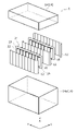
- FIG. 1 is an exploded perspective view of a battery module that is an example of an embodiment
- FIG. FIG. 2 is a plan view of part of the inside of the battery case of the battery module that is an example of the embodiment, viewed from above.
- FIG. 3 is a cross-sectional view taken along line AA of FIG. 2;
- FIG. 1 is an exploded perspective view of a battery module 1 that is an example of an embodiment.
- the battery module 1 includes a battery case 14 and a plurality of laminated batteries 10 stored in the battery case 14 in an upright posture.
- the two laminated batteries 10 are erected so that their main planes are substantially perpendicular to the bottom surface of the battery case 14 .
- a total of three partition walls 12 are provided between the two laminate batteries 10 and around the laminate batteries 10 .
- the number of laminate batteries 10 stored in the battery module 1 is not particularly limited. Also, the number of partition walls is not particularly limited.
- the X direction is the depth direction
- the Y direction is the width direction
- the Z direction is the height direction.
- the installation direction of the battery module 1 during use is not particularly limited. For example, the battery module 1 may be used with the Z direction parallel to the ground.
- the battery case 14 is formed by a case body 14a and a lid 16 that closes the opening of the case body 14a, forms a housing for the battery module 1, and stores the laminate battery 10 and the partition wall 12.
- the shape of the battery case 14 is not particularly limited as long as the laminate battery 10 and the partition wall 12 can be housed therein.
- the lid 16 has a rectangular parallelepiped shape with an opening on the lower surface, and is fitted with the case body 14a to close the upper opening of the case body 14a.
- the inside of the battery case 14 is filled with a mold resin (not shown in FIG. 1). That is, the mold resin fills the gap between the laminate battery 10 and the partition wall 12 housed inside the battery case 14 .
- the battery case 14 is provided with external terminals electrically connected to the laminated battery 10 housed in the battery case 14, but the external terminals are omitted in FIG.
- the laminate battery 10 is mainly used as a power source for power.
- the laminate battery 10 is used, for example, as a power source for motor-driven electric equipment such as electric vehicles, electric tools, electric assist bicycles, electric motorcycles, electric wheelchairs, electric tricycles, and electric carts.
- motor-driven electric equipment such as electric vehicles, electric tools, electric assist bicycles, electric motorcycles, electric wheelchairs, electric tricycles, and electric carts.
- the application of the laminated battery 10 is not limited, and it may be used as a power source for various electric devices used indoors and outdoors, such as cleaners, wireless devices, lighting devices, digital cameras, and video cameras.
- the laminate battery 10 has an electrode body, a housing portion 22 that houses the electrode body, and a sealing portion 23 that seals the periphery of the housing portion 22 .
- the laminate battery 10 may each have a plurality of housing portions.
- the laminate battery 10 has a cylindrical electrode body in each of the eight housing portions 22 arranged in the width direction.
- the housing portion 22 contains, for example, an electrolytic solution in addition to the electrode body.
- the electrolytic solution is, for example, a non-aqueous electrolyte containing a non-aqueous solvent and an electrolyte salt dissolved in the non-aqueous solvent.
- the laminate battery 10 has an exterior body composed of two laminate sheets.
- the laminate sheet a sheet obtained by laminating a metal layer and a resin layer can be used.
- a laminate sheet has, for example, two resin layers sandwiching a metal layer, and one of the resin layers is made of a thermocompression-bondable resin. Examples of metal layers include aluminum layers.
- the outer shape of the laminated battery 10 is, for example, substantially rectangular in plan view.
- the laminate sheets are joined together to form a sealing portion 23, thereby sealing the accommodating portion 22 in which the electrode assembly and the like are accommodated.
- the sealing portion 23 is formed between the edges of the laminate battery 10 and between the accommodation portions 22 .
- the sealing portion 23 seals the accommodating portions 22 and connects the adjacent accommodating portions 22 to each other.
- the housing portion 22 is a portion surrounded by the sealing portion 23, and is provided by forming a recess capable of housing the electrode assembly in at least one of the two laminate sheets.
- the dents are formed in both of the two laminate sheets, and the accommodating portions 22 bulge out on both sides in the depth direction.
- the cylindrical electrode body has a wound structure in which strip-shaped electrodes (positive electrode and negative electrode) are wound with separators interposed therebetween.
- shape of the electrode body is not limited to a cylindrical shape.
- number of electrode bodies included in the laminate battery 10 is not particularly limited.
- structure of the electrode body is not limited to the wound type, and may be, for example, a laminated type in which a plurality of positive electrodes and a plurality of negative electrodes are alternately laminated one by one.
- first electrode lead 24 extends from a position corresponding to each electrode body.
- second electrode leads 26 extend from positions corresponding to the respective electrode bodies. That is, at the upper end and the lower end of the laminate battery 10, the electrode leads are extended by the number of electrode bodies.
- first electrode lead 24 is connected to the positive electrode in the electrode body, and one end of the second electrode lead 26 is connected to the negative electrode in the electrode body.
- the first electrode lead 24 may be connected to the negative electrode and the second electrode lead 26 may be connected to the positive electrode.
- both the first electrode lead 24 and the second electrode lead 26 may extend from either the upper end or the lower end of the laminate battery 10 .
- current collecting members such as metal plates are connected to the first electrode lead 24 and the second electrode lead 26, respectively, and the current collecting members are connected to external terminals provided on the battery case 14 or the lid 16.
- electrical connection members such as collector members and external terminals are omitted.
- the plurality of laminated batteries 10 may be packed in the battery module 1 with the highest density in consideration of safety.
- adjacent laminate batteries 10 may be arranged such that the electrode bodies of the other laminate battery 10 are positioned between the adjacent electrode bodies of one laminate battery 10 . That is, the adjacent laminate batteries 10 may be arranged with a shift in the width direction so that the thickness in the depth direction is reduced.
- the partition walls 12 are provided between the two laminate batteries 10 and around the two laminate batteries 10, but the partition walls 12 are provided only between the plurality of laminate batteries 10.
- the partition wall 12 has an upright posture like the laminate battery 10, and is taller than the laminate battery 10, for example.
- the partition wall 12 has a function of holding the laminated battery 10 and positioning the laminated battery 10 until the mold resin is solidified, for example.
- the partition wall 12 may have, for example, a corrugated plate shape that repeats unevenness along the shape of the housing portion 22 that protrudes from the laminate battery 10, or may be a flat plate.
- the material of the partition 12 is not particularly limited, but preferably has insulating properties.
- Materials for the partition walls 12 include thermoplastic resins such as polypropylene (PP), polybutylene terephthalate (PBT), polycarbonate (PC), and Noryl (registered trademark) resin (modified PPE); elastic materials such as polyurethane; and the like can be exemplified.
- PP polypropylene
- PBT polybutylene terephthalate
- PC polycarbonate
- elastic materials such as polyurethane
- the exterior of the laminate battery 10 has insulating properties, the heat dissipation of the laminate battery 10 may be improved by using a metal plate such as aluminum or an aluminum alloy that has better heat dissipation than the mold resin 20 for the partition 12 .
- FIG. 2 is a plan view of part of the inside of the battery case 14 of the battery module 1, which is an example of the embodiment, viewed from above.
- 3 is a cross-sectional view taken along line AA of FIG. 2.
- the inside of the battery case 14 is filled with a mold resin 20.
- the operation of filling the mold resin 20 into the inside of the battery case 14 is carried out with the upper opening of the case main body 14a facing upward and the mold resin 20 being placed in the case main body 14a in an upright posture. Pour in.
- the mold resin 20 By filling the inside of the battery case 14 with the mold resin 20, it is possible to prevent the spread of fire by protecting peripheral batteries from overheating due to an abnormality in the laminate battery 10.
- FIG. the upper ends of the plurality of laminated batteries 10 protrude from the upper surface of the mold resin 20 .
- an exhaust path can be secured in the event of an abnormality. Specifically, due to the pressure of the gas generated in the housing portion 22, the gap between the two laminate sheets forming the sealing portion 23 at the upper end of the laminate battery 10 is opened to form an exhaust path.
- Examples of the mold resin 20 include acrylonitrile butadiene styrene (ABS) resin, polyvinyl chloride (PVC) resin, polycarbonate (PC) resin, polypropylene (PP) resin, polyethylene (PE) resin, polyamide (PA) resin, and urethane resin. etc. can be exemplified.
- ABS acrylonitrile butadiene styrene
- PVC polyvinyl chloride
- PC polycarbonate
- PP polypropylene
- PE polyethylene
- PA polyamide
- urethane resin urethane resin
- the housing portion 22 is surrounded and sealed by a sealing portion 23.
- the housing portion 22 includes an exhaust portion 22a and a body portion 22b.
- the exhaust portion 22a is a portion that protrudes upward from one side of the electrode body of the main body portion 22b.
- the position where the exhaust part 22a is provided is not particularly limited, but as shown in FIG.
- the word “upward” used here indicates the upward direction when the inside of the battery case 14 is filled with the mold resin, which is the X direction in FIG. , and indicates one side of the laminate battery 10 in the upright direction.
- the term “upper surface”, together with the term “upper surface” used in the claims, indicates the upward surface when the inside of the battery case 14 is filled with the mold resin.
- the body part 22b is a part that accommodates the electrode assembly and the electrolytic solution.
- the outer shape of the main body portion 22b is cylindrical, and substantially rectangular in plan view as shown in FIG.
- a first electrode lead 24 extends from the upper end of the body portion 22b
- a second electrode lead 26 extends from the lower end of the body portion 22b.
- Current collecting members such as metal plates are connected to the first electrode leads 24 and the second electrode leads 26, respectively, and the first electrode leads 24 and the second electrode leads 26 of the plurality of laminated batteries 10 are connected to each other, and the plurality of electrode leads 26 are connected to each other. of laminated batteries 10 are connected in parallel.
- M indicated by a dotted line represents the upper surface of the mold resin 20. That is, the space between the dotted line and the bottom surface of the case main body 14a is filled with the molding resin 20, and the body portion 22b is buried in the molding resin 20 in this embodiment. As a result, the body portion 22b that accommodates the electrode body can be surrounded by the mold resin 20, so that damage to the battery due to heat conduction to the surrounding batteries of the abnormal battery can be suppressed more remarkably.
- the upper surface of the mold resin 20 may be lower than the upper end of the main body portion 22b.
- the tip of the exhaust part 22a exists above the upper surface M of the mold resin 20.
- the interior of the battery case 14 is filled with the mold resin 20 except for the tip of the exhaust portion 22a.
- the sealing portion 23 above the exhaust portion 22a can be unsealed without the tip of the exhaust portion 22a being affected by the mold resin 20 .
- the gas discharged from the electrode body through the exhaust part 22 a after the sealing part 23 is opened passes through the exhaust path formed between the inner surface of the battery case 14 and the upper surface M of the mold resin 20 , and then the battery case 14 . is discharged to the outside of the battery case 14 through an exhaust hole provided in the .
- G1 represents the distance between the tip of the exhaust portion 22a and the upper surface M of the mold resin 20.
- the range of G1 in which the exhaust path from the laminate battery 10 can be secured varies depending on the internal pressure of the housing portion 22 in the event of an abnormality, the peel strength of the two laminate sheets in the sealing portion 23, etc., so it is particularly limited. However, it is, for example, 1 mm to 10 mm, preferably 2 mm to 8 mm.
- G2 represents the distance between the tip of the exhaust portion 22a and the upper end of the laminate battery 10.
- the range of G2 in which the exhaust path from the laminate battery 10 can be secured varies depending on the internal pressure of the housing portion 22 in the event of an abnormality, the peel strength of the two laminate sheets in the sealing portion 23, and the like, so it is particularly limited. However, it is, for example, 1 mm to 10 mm, preferably 2 mm to 8 mm.
- the battery case is filled with a predetermined amount of molding resin while the storage portion for the laminated battery includes the exhaust portion, so that gas is discharged from the laminated battery in the event of an abnormality. It is possible to prevent the spread of fire while securing an exhaust path for the purpose.
Abstract
Priority Applications (2)
| Application Number | Priority Date | Filing Date | Title |
|---|---|---|---|
| JP2023531890A JPWO2023276865A1 (fr) | 2021-06-28 | 2022-06-24 | |
| CN202280041917.9A CN117480678A (zh) | 2021-06-28 | 2022-06-24 | 电池模块 |
Applications Claiming Priority (2)
| Application Number | Priority Date | Filing Date | Title |
|---|---|---|---|
| JP2021106635 | 2021-06-28 | ||
| JP2021-106635 | 2021-06-28 |
Publications (1)
| Publication Number | Publication Date |
|---|---|
| WO2023276865A1 true WO2023276865A1 (fr) | 2023-01-05 |
Family
ID=84691280
Family Applications (1)
| Application Number | Title | Priority Date | Filing Date |
|---|---|---|---|
| PCT/JP2022/025229 WO2023276865A1 (fr) | 2021-06-28 | 2022-06-24 | Module de batterie |
Country Status (3)
| Country | Link |
|---|---|
| JP (1) | JPWO2023276865A1 (fr) |
| CN (1) | CN117480678A (fr) |
| WO (1) | WO2023276865A1 (fr) |
Citations (3)
| Publication number | Priority date | Publication date | Assignee | Title |
|---|---|---|---|---|
| WO2011061931A1 (fr) * | 2009-11-17 | 2011-05-26 | 本田技研工業株式会社 | Dispositif de stockage électrique |
| JP2012190734A (ja) | 2011-03-14 | 2012-10-04 | Hitachi Maxell Energy Ltd | 非水電解質電池モジュール |
| JP2014120760A (ja) * | 2012-12-14 | 2014-06-30 | Samsung Electro-Mechanics Co Ltd | スーパーキャパシタ及びその製造方法 |
-
2022
- 2022-06-24 WO PCT/JP2022/025229 patent/WO2023276865A1/fr active Application Filing
- 2022-06-24 CN CN202280041917.9A patent/CN117480678A/zh active Pending
- 2022-06-24 JP JP2023531890A patent/JPWO2023276865A1/ja active Pending
Patent Citations (3)
| Publication number | Priority date | Publication date | Assignee | Title |
|---|---|---|---|---|
| WO2011061931A1 (fr) * | 2009-11-17 | 2011-05-26 | 本田技研工業株式会社 | Dispositif de stockage électrique |
| JP2012190734A (ja) | 2011-03-14 | 2012-10-04 | Hitachi Maxell Energy Ltd | 非水電解質電池モジュール |
| JP2014120760A (ja) * | 2012-12-14 | 2014-06-30 | Samsung Electro-Mechanics Co Ltd | スーパーキャパシタ及びその製造方法 |
Also Published As
| Publication number | Publication date |
|---|---|
| CN117480678A (zh) | 2024-01-30 |
| JPWO2023276865A1 (fr) | 2023-01-05 |
Similar Documents
| Publication | Publication Date | Title |
|---|---|---|
| JP6474836B2 (ja) | 電池モジュール及びそれを含む電池パック | |
| JP6166475B2 (ja) | 電力貯蔵装置用電池パック | |
| JP6090711B2 (ja) | 2次電池及び電池モジュール | |
| JP6101823B2 (ja) | 新規な構造の電池モジュール及びこれを含む電池パック | |
| JP5022031B2 (ja) | フィルム外装電気デバイス、枠部材およびフィルム外装電気デバイス収納システム | |
| CN104541386B (zh) | 具有通气引导部分的电池模块 | |
| KR101216422B1 (ko) | 실링부의 절연성이 향상된 이차전지 | |
| JP5949608B2 (ja) | モジュール用筐体および組電池 | |
| JP5364650B2 (ja) | 蓄電デバイス、蓄電デバイス間の接続構造、蓄電モジュール | |
| CN104488127B (zh) | 具有组装联接结构的电池模块 | |
| JP6743664B2 (ja) | 蓄電装置及び蓄電装置の製造方法 | |
| KR101326182B1 (ko) | 외장부재와 카트리지를 포함하는 단위모듈에 기반한 전지모듈 | |
| KR20070091387A (ko) | 중대형 전지모듈 | |
| US10236487B2 (en) | Battery module | |
| JP2007087907A (ja) | 蓄電体セルのケース構造 | |
| KR20160129596A (ko) | 배터리 팩 및 그 제조 방법 | |
| KR20190042215A (ko) | 가스 배출구를 포함하는 이차전지용 파우치형 케이스 | |
| KR101517044B1 (ko) | 다수의 전극조립체 수납부가 형성된 케이스를 포함하는 이차전지 | |
| WO2007032270A1 (fr) | Couvercle isolant et ensemble dispositif electrique emballe sous film | |
| WO2016067487A1 (fr) | Dispositif d'alimentation électrique | |
| KR101472882B1 (ko) | 셀 커버 체결부 및 수납부 체결부를 포함하는 구조의 전지모듈 | |
| JP2003338269A (ja) | 二次電池モジュール | |
| WO2006059469A1 (fr) | Ensemble electrique emballe dans du film | |
| WO2023276865A1 (fr) | Module de batterie | |
| JP5248781B2 (ja) | 電気デバイスモジュール及び電気デバイスモジュール集合体 |
Legal Events
| Date | Code | Title | Description |
|---|---|---|---|
| 121 | Ep: the epo has been informed by wipo that ep was designated in this application |
Ref document number: 22833012 Country of ref document: EP Kind code of ref document: A1 |
|
| WWE | Wipo information: entry into national phase |
Ref document number: 2023531890 Country of ref document: JP |
|
| WWE | Wipo information: entry into national phase |
Ref document number: 2022833012 Country of ref document: EP |
|
| NENP | Non-entry into the national phase |
Ref country code: DE |
|
| ENP | Entry into the national phase |
Ref document number: 2022833012 Country of ref document: EP Effective date: 20240129 |