WO2023276745A1 - レーザ加工装置及びレーザ光の焦点位置の自動補正方法 - Google Patents
レーザ加工装置及びレーザ光の焦点位置の自動補正方法 Download PDFInfo
- Publication number
- WO2023276745A1 WO2023276745A1 PCT/JP2022/024468 JP2022024468W WO2023276745A1 WO 2023276745 A1 WO2023276745 A1 WO 2023276745A1 JP 2022024468 W JP2022024468 W JP 2022024468W WO 2023276745 A1 WO2023276745 A1 WO 2023276745A1
- Authority
- WO
- WIPO (PCT)
- Prior art keywords
- laser
- focal position
- laser beam
- diameter
- processing
- Prior art date
- Legal status (The legal status is an assumption and is not a legal conclusion. Google has not performed a legal analysis and makes no representation as to the accuracy of the status listed.)
- Ceased
Links
Images





Classifications
-
- B—PERFORMING OPERATIONS; TRANSPORTING
- B23—MACHINE TOOLS; METAL-WORKING NOT OTHERWISE PROVIDED FOR
- B23K—SOLDERING OR UNSOLDERING; WELDING; CLADDING OR PLATING BY SOLDERING OR WELDING; CUTTING BY APPLYING HEAT LOCALLY, e.g. FLAME CUTTING; WORKING BY LASER BEAM
- B23K26/00—Working by laser beam, e.g. welding, cutting or boring
- B23K26/02—Positioning or observing the workpiece, e.g. with respect to the point of impact; Aligning, aiming or focusing the laser beam
- B23K26/04—Automatically aligning, aiming or focusing the laser beam, e.g. using the back-scattered light
-
- B—PERFORMING OPERATIONS; TRANSPORTING
- B23—MACHINE TOOLS; METAL-WORKING NOT OTHERWISE PROVIDED FOR
- B23K—SOLDERING OR UNSOLDERING; WELDING; CLADDING OR PLATING BY SOLDERING OR WELDING; CUTTING BY APPLYING HEAT LOCALLY, e.g. FLAME CUTTING; WORKING BY LASER BEAM
- B23K26/00—Working by laser beam, e.g. welding, cutting or boring
- B23K26/02—Positioning or observing the workpiece, e.g. with respect to the point of impact; Aligning, aiming or focusing the laser beam
- B23K26/06—Shaping the laser beam, e.g. by masks or multi-focusing
- B23K26/064—Shaping the laser beam, e.g. by masks or multi-focusing by means of optical elements, e.g. lenses, mirrors or prisms
-
- B—PERFORMING OPERATIONS; TRANSPORTING
- B23—MACHINE TOOLS; METAL-WORKING NOT OTHERWISE PROVIDED FOR
- B23K—SOLDERING OR UNSOLDERING; WELDING; CLADDING OR PLATING BY SOLDERING OR WELDING; CUTTING BY APPLYING HEAT LOCALLY, e.g. FLAME CUTTING; WORKING BY LASER BEAM
- B23K26/00—Working by laser beam, e.g. welding, cutting or boring
- B23K26/02—Positioning or observing the workpiece, e.g. with respect to the point of impact; Aligning, aiming or focusing the laser beam
- B23K26/03—Observing, e.g. monitoring, the workpiece
- B23K26/032—Observing, e.g. monitoring, the workpiece using optical means
-
- B—PERFORMING OPERATIONS; TRANSPORTING
- B23—MACHINE TOOLS; METAL-WORKING NOT OTHERWISE PROVIDED FOR
- B23K—SOLDERING OR UNSOLDERING; WELDING; CLADDING OR PLATING BY SOLDERING OR WELDING; CUTTING BY APPLYING HEAT LOCALLY, e.g. FLAME CUTTING; WORKING BY LASER BEAM
- B23K26/00—Working by laser beam, e.g. welding, cutting or boring
- B23K26/02—Positioning or observing the workpiece, e.g. with respect to the point of impact; Aligning, aiming or focusing the laser beam
- B23K26/04—Automatically aligning, aiming or focusing the laser beam, e.g. using the back-scattered light
- B23K26/046—Automatically focusing the laser beam
-
- B—PERFORMING OPERATIONS; TRANSPORTING
- B23—MACHINE TOOLS; METAL-WORKING NOT OTHERWISE PROVIDED FOR
- B23K—SOLDERING OR UNSOLDERING; WELDING; CLADDING OR PLATING BY SOLDERING OR WELDING; CUTTING BY APPLYING HEAT LOCALLY, e.g. FLAME CUTTING; WORKING BY LASER BEAM
- B23K26/00—Working by laser beam, e.g. welding, cutting or boring
- B23K26/20—Bonding
- B23K26/21—Bonding by welding
- B23K26/22—Spot welding
-
- B—PERFORMING OPERATIONS; TRANSPORTING
- B23—MACHINE TOOLS; METAL-WORKING NOT OTHERWISE PROVIDED FOR
- B23K—SOLDERING OR UNSOLDERING; WELDING; CLADDING OR PLATING BY SOLDERING OR WELDING; CUTTING BY APPLYING HEAT LOCALLY, e.g. FLAME CUTTING; WORKING BY LASER BEAM
- B23K26/00—Working by laser beam, e.g. welding, cutting or boring
- B23K26/70—Auxiliary operations or equipment
Definitions
- the present disclosure relates to a laser processing apparatus and an automatic correction method for the focal position of laser light.
- Patent Documents 1 to 5 there are known methods of adjusting the posture of a laser processing device and the focus position of a laser beam based on the state and shape of a member after processing.
- the focal position of the laser beam may deviate from the set position. For example, such a problem occurs after replacing the laser head of the laser processing apparatus.
- a well-known method is to measure the beam diameter of the laser beam on the surface of the workpiece and correct the positional deviation based on the measurement result when the focal position of the laser beam is shifted.
- the present disclosure has been made in view of this point, and its object is to provide a laser processing apparatus capable of correcting the focal position of laser light without requiring dedicated equipment or maintenance workers, and automatic correction of the focal position of laser light. It is to provide a method.
- a laser processing apparatus includes a laser head that irradiates a laser beam, a camera that acquires a surface image of a workpiece after being irradiated with the laser beam, and the acquired surface
- An image processing unit that performs image processing on an image to calculate the diameter of the machining mark, an automatic focus control unit that derives the optimum focus position of the laser beam based on the diameter of the machining mark, and derivation of the automatic focus control unit.
- a method for automatically correcting the focal position of a laser beam is a method for automatically correcting the focal position of a laser beam emitted from a laser head, comprising: a first step of spot-irradiating a workpiece with the laser beam; a second step of acquiring a surface image of the processed member after being irradiated with the laser beam; and processing formed on the surface of the processed member based on the surface image of the processed member acquired in the second step. a third step of measuring the diameter of the trace; a fourth step of deriving an optimum focal position of the laser beam based on the diameter of the machining scar; and a fifth step of moving the laser head or an optical component inside the laser head in the direction in which the laser beam is emitted.
- FIG. 1 is a schematic configuration diagram of a laser processing apparatus according to Embodiment 1.
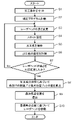
- FIG. FIG. 2 is a flowchart showing a procedure for automatically correcting the focal position of laser light.
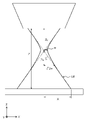
- FIG. 3 is a schematic diagram showing the relationship between the beam diameter of laser light and the focal position.
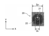
- FIG. 4A is a photograph showing an example of processing traces and a heat affected zone formed on the surface of a processed member.
- FIG. 4B is a schematic cross-sectional view of the traces of processing and the heat-affected zone.
- FIG. 5 is a schematic diagram showing how the size of the processing trace and the heat-affected zone changes when the height of the laser head is changed.
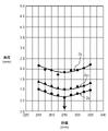
- FIG. 6 is an example showing the relationship between the distance from the tip of the laser head to the workpiece and the diameter of the machining marks and the heat affected zone.
- FIG. 7 is a schematic configuration diagram of a laser processing apparatus according to Embodiment 2.
- FIG. 8 is a flow chart showing the procedure for automatically correcting the focal position of the laser beam.
- FIG. 9 is a photograph showing an example of processing traces and heat-affected zones formed on the surface of a processed member.
- FIG. 10 is a schematic diagram showing the relationship between the beam diameter of laser light and the focal position.
- FIG. 11A is a schematic diagram showing the relationship between the distance from the center of the laser beam and the light intensity.
- FIG. 11B is a schematic diagram showing the relationship between the distance from the center of the laser beam and the member temperature.
- FIG. 12A and 12B are schematic diagrams showing how the processing marks and the size of the heat-affected zone change when the height of the laser head is changed.
- FIG. 13 is an example showing the relationship between the distance from the tip of the laser head to the workpiece and the diameter of the machining marks and the heat affected zone.
- FIG. 1 shows a schematic configuration diagram of a laser processing apparatus according to Embodiment 1.
- a laser processing apparatus 10 includes a laser head 1, a camera 3, an image processing section 4, an autofocus control section 5, and a driving section 6. ing.
- the laser processing device 10 also includes an optical fiber 2 .
- the laser processing apparatus 10 includes a laser oscillator that generates a laser beam LB and a laser control unit that controls the laser oscillator. Description is omitted.
- the optical axis direction of the laser beam LB emitted from the laser head 1 (hereinafter sometimes simply referred to as the emission direction of the laser beam LB) is sometimes referred to as the Z direction.
- the two directions that are located in a plane that intersects the Z direction and intersect with each other are sometimes called the X direction and the Y direction.
- the surface of the plate-like processed member 20 corresponds to a plane including the X direction and the Y direction.
- the laser head 1 receives the laser beam LB from the optical fiber 2 and irradiates it toward the workpiece 20 .
- the laser head 1 has a plurality of optical components inside, for example, a collimating lens and a condensing lens (both not shown).
- a protective glass (not shown) is provided so as to cover an opening (not shown) provided at the tip of the laser head 1 .
- other optical components such as a reflecting mirror may be arranged inside the laser head 1 .
- the laser beam LB When the laser beam LB enters the inside of the laser head 1 from the optical fiber 2, it is converted into parallel beams by a collimating lens (not shown). The laser beam LB is further condensed at a predetermined focal position by a condensing lens (not shown).
- the optical fiber 2 is an optical member that transmits laser light LB generated by a laser oscillator (not shown) to the laser head 1 .
- the camera 3 is attached to the laser head 1 and captures an image of the surface of the workpiece 20 after being irradiated with the laser beam LB.
- the camera 3 is provided with an imaging element (not shown) such as a CMOS image sensor.
- an illumination light source (not shown) for capturing a surface image of the workpiece 20 may be provided.
- a mirror (not shown) may be provided inside the laser head 1 for causing the light reflected by the surface of the workpiece 20 to enter the camera 3 .
- the image processing unit 4 performs image processing on the surface image of the workpiece 20 acquired by the camera 3 to obtain a processing mark 21 (see FIGS. 4A and 4B) and a heat-affected zone 22 formed around the processing mark 21 ( (See FIGS. 4A and 4B). In addition, the image processing unit 4 calculates the diameter 2x (see FIG. 3) of the machining mark 21 .
- the processing mark 21 is a mark obtained by cooling and solidifying a melted portion formed when the surface of the processed member 20 is irradiated with the laser beam LB.
- the temperature around the melted portion rises significantly although the melted portion does not melt.
- the properties of the workpiece 20, such as texture and composition may change.
- the surface unevenness of the processed member 20 may change significantly.
- a heat-affected zone 22 is a portion where the properties, surface irregularities, and the like formed around the work mark 21 are changed due to temperature rise when the work mark 21 is formed. More on these later.
- the automatic focus control unit 5 derives the optimum focus position of the laser beam LB based on the correction program described later and the diameter of the machining mark 21 calculated by the image processing unit 4 (see FIGS. 3 and 4A and 4B). . A procedure for deriving the optimum focus position will be described later.
- the image processing unit 4 is composed of, for example, a known GPU (Graphic Processing Unit).
- the autofocus control unit 5 is composed of, for example, a known CPU (Central Processing Unit).
- the image processing unit 4 and the autofocus control unit 5 may be configured as functional blocks inside one GPU or CPU. If the autofocus control unit 5 has a memory (not shown), the correction program described above may be stored in the memory. A correction program is called from memory to automatically correct the focus position. Note that the correction program may be stored in another memory (not shown). In that case, another memory may be provided outside the laser processing apparatus 10 . It is only required that data can be exchanged with the automatic focus control unit 5 .
- the drive unit 6 moves the laser head 1 in the Z direction, which is the emission direction of the laser beam LB, so that the laser beam LB is condensed at the optimum focus position based on the derivation result of the autofocus control unit 5 .
- the drive unit 6 is composed of, for example, a ball screw (not shown) extending in the Z direction and a stepping motor (not shown) 9 connected to the ball screw. Based on the information of the optimum focus position received from the automatic focus control unit 5, the stepping motor is driven to rotate the ball screw and move the laser head 1 to the desired position in the Z direction.
- FIG. 2 shows a flowchart of the procedure for automatically correcting the focal position of the laser beam
- FIG. 3 schematically shows the relationship between the beam diameter of the laser beam and the focal position
- FIG. 4A shows an example of the working marks and the heat affected zone formed on the surface of the processed member
- FIG. 4B shows a cross-sectional schematic diagram of the working marks and the heat affected zone
- FIG. 5 is a schematic diagram showing how the size of the processing trace and the heat-affected zone changes when the height of the laser head is changed.
- FIG. 6 is an example showing the relationship between the distance from the tip of the laser head to the workpiece and the diameter of the machining marks and the heat affected zone.
- step S1 the workpiece 20 is set at a predetermined position (step S1), and the correction program is started (step S2).
- step S3 the height of the laser head 1 in the Z direction is changed (step S3), and the workpiece 20 is spot-welded by spot irradiation with the laser beam LB (step S4). Further, the camera 3 captures images of the work mark 21 and the heat-affected zone 22 formed by spot welding (step S5), and measures the diameter 2x of the work mark 21 based on the obtained image (step S6).
- step S ⁇ b>7 may be determined inside the laser processing apparatus 10 . For example, the number of operation start times of the drive unit 6 may be counted by a control unit (not shown). Alternatively, step S7 may be determined by an on-site worker.
- N is an integer of 2 or more. N is preferably the minimum value required to derive the best focus position. This is because the preprocessing for correcting the focal position is simplified, and the downtime of the laser processing apparatus 10 can be shortened.
- step S7 If the determination result in step S7 is affirmative, the difference between the distance z obtained in each of the N trials and the focal position z0 is calculated based on the diameter 2x of the machining mark 21 measured in step S6. (step S8). Based on the calculation result in step S8, the optimum focal position is derived (step S9). The laser head 1 is moved in the Z direction so that the laser beam LB is condensed at the optimum focal position (step S10), and the automatic correction is completed. The automatic correction procedure described so far will be further described.
- the beam diameter of the laser beam LB emitted from the laser head 1 is the smallest at the beam waist.
- the laser beam LB travels further from this position, the laser beam LB spreads with a predetermined beam divergence angle and the beam diameter increases.
- ⁇ be the wavelength of the laser beam LB.
- the beam diameter of the laser beam LB on the surface of the workpiece 20 is assumed to be 2x
- the focal position of the laser beam LB with respect to the tip of the laser head 1 is assumed to be z0 .
- z be the distance from the tip of the laser head 1 to the surface of the workpiece 20, and 2w be the beam diameter of the laser light LB at the beam waist.
- zR be the Rayleigh length of the laser beam LB
- ⁇ be the beam divergence angle of the laser beam LB.
- the beam diameter of the laser beam LB is the smallest at the beam waist. Therefore, if the surface of the processing member 20 is arranged at this position, the processing member 20 can be laser-processed with the beam being most focused. That is, this position corresponds to the optimum focal position. Also, as is clear from FIG. 3 and equation (2), the difference between the distance z and the focal position z0 is calculated, and the tip of the laser head 1 is moved to the distance z that minimizes the difference. By adjusting in this way, the laser beam LB emitted from the laser head 1 is condensed at the optimum focal position. As is clear from FIG. 3, the theoretical minimum value of the difference between the distance z and the focal position z0 is w/tan ⁇ .
- the inventors of the present application focused on the processing marks 21 formed by spot welding instead of directly measuring the beam diameter.
- the size of the machining mark 21 corresponds to the beam diameter of the laser beam LB on the surface of the workpiece 20 .
- the optimum focal position can be derived by the procedure described above.
- FIG. 4A when the workpiece 20 is spot-welded, a circular portion formed in the center and an annular portion having a different state from the surface of the workpiece 20 are formed around it.
- the former is the machining mark 21 and the latter is the heat affected zone 22 described above.
- FIG. 4B in the heat-affected zone 22, due to the influence of heat propagation, the diameter 2y1 on the irradiation surface of the laser beam LB becomes larger than the diameter 2y2 on the surface opposite to the irradiation surface. .
- both the diameter 2x of the machining mark 21 and the diameter 2y1 of the heat-affected zone 22 change depending on the focus state of the laser beam LB. If the height of the laser head 1 is not set appropriately, in the example shown in FIG. 1 increases both. Similarly, when the laser beam LB is shifted toward the negative focus, both the diameter 2x of the machining mark 21 and the diameter 2y1 of the heat-affected zone 22 increase. When the laser beam LB is in a just-focus state, that is, when the laser beam LB is at the optimum focal position, both the diameter 2x of the machining mark 21 and the diameter 2y1 of the heat-affected zone 22 are minimized.
- FIG. 6 shows an example of changes in the diameter 2x of the machining mark 21 and the diameter 2y1 of the heat-affected zone 22 with respect to the distance z.
- changes in the diameter 2y2 of the heat affected zone 22 are also shown.
- the diameter 2x of the machining mark 21 and the diameter 2y1 of the heat-affected zone 22 tended to change in the same way with respect to the distance z, and both were minimized when the distance z was 280 mm.
- the optimum focal position can be derived using either the diameter 2x of the machining mark 21 or the diameter 2y1 of the heat-affected zone 22 .
- the diameter 2y1 of the heat-affected zone 22 is more affected by variations in the material of the workpiece 20 than the diameter 2x of the machining mark 21 .
- the peripheral edge of the heat-affected zone 22 has less clear contrast than the peripheral edge of the machining mark 21, the measurement accuracy of the diameter 2y1 may decrease.
- the inventors of the present application used the diameter 2x of the machining mark 21 and substituted it into the beam diameter of the laser light LB in equations (1) and (2) to derive the optimum focal position.
- the laser processing apparatus 10 includes the laser head 1 that irradiates the laser beam LB, the camera 3 that acquires the surface image of the workpiece 20 after being irradiated with the laser beam, at least.
- the laser processing apparatus 10 includes an image processing unit 4 that performs image processing on the acquired surface image to calculate the diameter 2x of the processing mark 21, and an optimum focal position of the laser beam LB based on the diameter 2x of the processing mark 21. and an automatic focus control unit 5 for deriving .
- the laser processing apparatus 10 also includes a drive unit that moves the laser head 1 in the direction in which the laser beam LB is emitted so that the laser beam LB is condensed at the optimum focal position based on the result of the derivation of the autofocus control unit 5. 6.
- the on-site worker who operates the laser processing device 10 automatically corrects the focal position of the laser beam LB without requiring dedicated equipment or a maintenance worker with special skills. be able to. In addition, this can reduce the downtime of the laser processing apparatus 10, thereby suppressing a decrease in processing productivity.
- the image processing unit 4 identifies the processing mark 21 in the surface image of the processing member 20 and the heat-affected zone 22 formed around the processing mark 21, and calculates the diameter 2x of the processing mark 21.
- the beam diameter of the laser beam LB on the surface of the workpiece 20 is assumed to be 2x
- the focal position of the laser beam LB with respect to the tip of the laser head 1 is assumed to be z0 .
- Let z be the distance from the tip of the laser head 1 to the surface of the workpiece 20, and 2w be the beam diameter of the laser light LB at the beam waist.
- Let zR be the Rayleigh length of the laser beam LB, and let ⁇ be the beam divergence angle of the laser beam LB.
- the autofocus control unit 5 derives the distance z that minimizes the difference from the focus position z0 as the optimum focus position.
- the theoretical minimum value of the difference between the distance z and the focal position z0 is w/tan ⁇ .
- the autofocus control section 5 may derive the distance z at which the difference from the focus position z0 is a predetermined value as the optimum focus position.
- the predetermined value in this case is the lower limit value that the distance z can take due to the structure of the laser processing apparatus 10 or the shape of the workpiece 20 .
- the optimal focal position can be derived with high accuracy.
- the method for automatically correcting the focal position of the laser beam LB emitted from the laser head 1 according to the first embodiment includes at least the following steps.
- the method for automatically correcting the focal position of the laser beam LB consists of a first step (step S4 in FIG. 2) of spot-irradiating the workpiece 20 with the laser beam LB, and a surface image of the workpiece 20 after being irradiated with the laser beam LB. and a second step (step S5 in FIG. 2) of acquiring the A third step (step S6 in FIG. 2) of measuring the diameter 2x of the processing mark 21 formed on the surface of the processing member 20 based on the surface image of the processing member 20 acquired in the second step (step S6 in FIG. 2); and a fourth step (step S9 in FIG. 2) of deriving the optimum focal position of the laser beam LB based on the diameter 2x of the laser beam LB.
- the fifth step (step S10 in FIG. 2) is provided for moving the laser head 1 in the Z direction, which is the emission direction of the laser beam LB, so that the laser beam LB is condensed at the optimum focal position.
- the on-site worker who operates the laser processing device 10 automatically corrects the focal position of the laser beam LB without requiring dedicated equipment or a maintenance worker with special skills. be able to. In addition, this can reduce the downtime of the laser processing apparatus 10, thereby suppressing a decrease in processing productivity.
- the processing marks 21 in the surface image of the processing member 20 and the heat-affected zones 22 formed around the processing marks 21 are identified, and the diameter 2x of the processing marks 21 is calculated.
- the on-site worker who operates the laser processing device 10 can automatically correct the focal position of the laser beam LB without requiring dedicated equipment or a maintenance worker with special skills. can be done.
- the focal position z0 satisfies the relationship shown in Equation (2), and the fourth step derives the distance z at which the difference from the focal position z0 is a predetermined value as the optimum focal position.
- the optimal focal position can be derived with high accuracy.
- the laser head 1 is moved in the Z direction so that the laser beam LB is condensed at the optimum focal position.
- the focal position of the laser beam LB can be changed by moving the collimator lens in the Z direction.
- the power of the laser beam LB irradiated to the workpiece 20 during spot welding may be different from the power during actual machining. If the power of the laser beam LB is too large, spatters may scatter on the surface of the processing mark 21 and its surroundings, and the measurement accuracy of the diameter 2x of the processing mark 21 may be lowered.
- the power of the laser beam LB used for automatic correction may be smaller than the power for actual machining. For example, in the example shown in FIG. 6, the power of the laser beam LB is 0.3 kW. However, the power of the laser beam LB used for automatic correction must be such that the machining marks 21 can be clearly recognized by the camera 3 .
- the processing member 20 used for automatic correction may differ from the member to be actually processed in shape and material. It suffices if the machining marks 21 can be reliably formed by the irradiation of the laser beam LB. Moreover, it is sufficient that the processing mark 21 can be clearly recognized on the heat affected zone 22 by the camera 3 .
- FIG. 7 shows a schematic configuration diagram of a laser processing apparatus according to Embodiment 2.
- a laser processing apparatus 10 includes a laser head 1, a drive section 6, a drive control section 40, and an input section 50. As shown in FIG.
- the laser processing device 10 also includes an optical fiber 2 .
- the laser processing apparatus 10 includes a laser oscillator that generates a laser beam LB and a laser control unit that controls the laser oscillator. Description is omitted.
- the optical axis direction of the laser beam LB emitted from the laser head 1 (hereinafter sometimes simply referred to as the emission direction of the laser beam LB) is sometimes referred to as the Z direction.
- the two directions that are located in a plane that intersects the Z direction and intersect with each other are sometimes called the X direction and the Y direction.
- the surface of the plate-like processing member 20 corresponds to a plane including the X direction and the Y direction.
- the laser head 1 receives the laser beam LB from the optical fiber 2 and irradiates it toward the workpiece 20 .
- the laser head 1 has a plurality of optical components inside, for example, a collimator lens 1a and a condenser lens 1b.
- a protective glass (not shown) is provided so as to cover an opening (not shown) provided at the tip of the laser head 1 .
- other optical components such as a reflecting mirror may be arranged inside the laser head 1 .
- the laser beam LB When the laser beam LB enters the inside of the laser head 1 from the optical fiber 2, it is converted into parallel beams by the collimator lens 1a. The laser beam LB is further condensed to a predetermined focal position by the condensing lens 1b.
- the optical fiber 2 is an optical member that transmits laser light LB generated by a laser oscillator (not shown) to the laser head 1 .
- the drive unit 6 moves the laser head 1 in the Z direction, which is the emission direction of the laser beam LB.
- the drive control section 40 controls the operation of the drive section 6 .
- the input unit 50 is provided to input parameters related to the amount of movement of the drive unit 6 to the drive control unit 40 .
- the drive unit 6 extends in the Z direction and is composed of a ball screw (not shown) connected to the laser head 1 and a stepping motor (not shown) connected to the ball screw.
- the drive control unit 40 is a motor driver, and the input unit 50 is a teaching pendant. For example, the distance z and the focus position z 0 , which will be described later, or the difference between them are input to the drive control unit 40 from the teaching pendant.
- the drive unit 6 is not particularly limited to the structure described above.
- a manual driving unit 6 may be used as long as the amount of movement can be visually recognized by an on-site worker.
- the drive control unit 40 can be omitted.
- the input unit 50 can be omitted for the purpose of correcting the focal position of the laser beam LB.
- FIG. 8 shows a flowchart of the procedure for correcting the focal position of the laser beam
- FIG. 9 shows an example of the machining mark and the heat-affected zone formed on the surface of the workpiece
- FIG. The relationship with the focal position is schematically shown.
- FIG. 11A schematically shows the relationship between the distance from the center of the laser beam and the light intensity
- FIG. 11B schematically shows the relationship between the distance from the center of the laser beam and the member temperature.
- FIG. 12 schematically shows how the processing marks and heat-affected zone change in size when the height of the laser head is changed.
- FIG. 13 is an example showing the relationship between the distance from the tip of the laser head to the workpiece and the diameter of the machining marks and the heat affected zone.
- the workpiece 20 is set at a predetermined position (step S1), and the laser head 1 is moved to the initial position (step S2).
- the workpiece 20 is spot-welded by spot irradiation with the laser beam LB (step S3). Further, the diameter 2x of the working marks 21 formed by spot welding is measured (step S4).
- the processing mark 21 is a mark formed by cooling and solidifying a melted portion formed when the surface of the processed member 20 is irradiated with the laser beam LB (see FIG. 9). Further, in measuring the diameter 2x of the working mark 21, it is necessary to distinguish between the heat affected zone 22 formed around the working mark 21 and the working mark 21.
- FIG. 9 is a mark formed by cooling and solidifying a melted portion formed when the surface of the processed member 20 is irradiated with the laser beam LB (see FIG. 9). Further, in measuring the diameter 2x of the working mark 21, it is necessary to distinguish between the heat affected zone 22 formed around the working mark 21 and the working mark 21.
- the temperature around it rises significantly although it does not melt.
- the properties of the workpiece 20, such as texture and composition may change.
- the surface unevenness of the processed member 20 may change significantly.
- the portion where the properties and surface unevenness, etc., formed around the processing mark 21 are changed due to the temperature rise when the processing mark 21 is formed is referred to as a heat-affected zone 22 (see FIG. 9) in this specification. . More on these later.
- the diameter of the processing mark 21 after spot welding may be directly measured with a measuring instrument such as a vernier caliper.
- the processing mark 21 after spot welding may be imaged, and the diameter 2x of the processing mark 21 may be measured from the image.
- the distance z from the tip of the laser head 1 to the surface of the workpiece 20 (hereinafter sometimes simply referred to as the distance z) and the laser A difference from the focal position z 0 of the laser beam LB with the tip of the head 1 as a reference (hereinafter sometimes simply referred to as the focal position z 0 ) is calculated (step S5).
- the beam diameter of the laser beam LB emitted from the laser head 1 is the smallest at the beam waist.
- the laser beam LB travels further from this position, the laser beam LB spreads with a predetermined beam divergence angle and the beam diameter increases.
- ⁇ be the wavelength of the laser beam LB.
- the beam diameter of the laser beam LB on the surface of the workpiece 20 is assumed to be 2x, and the focal position of the laser beam LB with respect to the tip of the laser head 1 is assumed to be z0 .
- the beam diameter of the laser light LB at the beam waist is 2w.
- zR be the Rayleigh length of the laser beam LB
- ⁇ be the beam divergence angle of the laser beam LB.
- the beam diameter of the laser beam LB is the smallest at the beam waist. Therefore, if the surface of the processing member 20 is arranged at this position, the processing member 20 can be laser-processed with the beam being most focused.
- the difference between the distance z and the focal position z0 is obtained, and the tip of the laser head 1 is moved to the distance z that minimizes the difference.
- the laser beam LB emitted from the laser head 1 is condensed at the optimum focal position.
- the theoretical minimum value of the difference between the distance z and the focal position z0 is w/tan ⁇ .
- each parameter described above is acquired in advance.
- the wavelength ⁇ is known in advance.
- the focal position z 0 , the Rayleigh length z R , the beam diameter 2w and the beam divergence angle ⁇ are obtained experimentally in advance. These values may be stored in a format that can be visually recognized by an on-site worker during focal position correction work, and can be input to the input unit as necessary. For example, it may be saved in a personal computer used by a worker on site, or may be saved as a paper file.
- the laser head 1 is moved in the Z direction so that the difference is minimized (step S6), and correction of the focus position is completed.
- the inventors of the present application focused on the processing marks 21 formed by spot welding instead of directly measuring the beam diameter.
- the size of the machining mark 21 corresponds to the beam diameter of the laser beam LB on the surface of the workpiece 20 .
- the light intensity of the laser beam LB has a Gaussian distribution and satisfies the relationship shown in Equation (3).
- twice the distance r when the light intensity I/ I0 is 1/e2 is often selected as the aforementioned 2x.
- the member temperature T which is the temperature of the workpiece 20 also has a distribution close to the Gaussian distribution with respect to the distance r from the center of the laser beam LB.
- the member temperature T satisfies the relationship represented by Equation (4).
- T(R,Z,W) member temperature T as a function of R,Z,W ⁇ : Attenuation rate of laser light
- K Thermal conductivity
- F(R): Bessel transformation of f(R) exp(-R 2 )
- R: r/w Z: z/w W: ⁇ w is.
- the shapes of the processing marks 21 and the heat-affected zone 22 are substantially circular in plan view, as shown in FIGS. 10 and 11B.
- both the diameter 2x of the machining mark 21 and the diameter 2y1 of the heat-affected zone 22 change depending on the focus state of the laser beam LB. In the case where the height of the laser head 1 is not set appropriately, in the example shown in FIG. 1 increases both. Similarly, when the laser beam LB is shifted toward the negative focus, both the diameter 2x of the machining mark 21 and the diameter 2y1 of the heat-affected zone 22 increase. When the laser beam LB is in a just-focus state, that is, when the laser beam LB is at the optimum focal position, both the diameter 2x of the machining mark 21 and the diameter 2y1 of the heat-affected zone 22 are minimized.
- FIG. 13 shows an example of changes in the diameter 2x of the machining mark 21 and the diameter 2y1 of the heat-affected zone 22 with respect to the distance z.
- the difference between the distance z and the focal position z0 can be calculated using either the diameter 2x of the machining mark 21 or the diameter 2y1 of the heat-affected zone 22.
- the diameter 2y1 of the heat-affected zone 22 is more affected by variations in the material of the workpiece 20 than the diameter 2x of the machining mark 21 .
- the peripheral edge of the heat-affected zone 22 has less clear contrast than the peripheral edge of the machining mark 21, the measurement accuracy of the diameter 2y1 may decrease.
- the inventors of the present application substitute the diameter 2x of the machining mark 21 into the beam diameter of the laser beam LB in the equations (1) and (2), and calculate the difference between the distance z and the focal position z0 . I made it Thus, by setting the diameter of the machining mark 21 to 2x in the formulas (1) and (2), the focal position of the laser beam LB can be corrected by the procedure described above.
- the method of correcting the focal position of the laser beam LB emitted from the laser head 1 according to the second embodiment includes at least the following steps.
- the method of correcting the focal position of the laser beam LB consists of a first step (step S3 in FIG. 8) of spot-irradiating the laser beam LB onto the workpiece 20, and adjusting the diameter 2x of the machining mark 21 formed on the surface of the workpiece 20. and a second step of measuring (step S4 in FIG. 8).
- a third step (FIG. 8 and a fourth step (step S6 in FIG. 8) of moving the laser head 1 in the Z direction, which is the emission direction of the laser beam LB, so that the difference is minimized.
- the on-site worker who operates the laser processing device 10 can correct the focal position of the laser beam LB without requiring dedicated equipment or a maintenance worker with special skills. .
- this can reduce the downtime of the laser processing apparatus 10, thereby suppressing a decrease in processing productivity.
- laser processing is not performed with the focal position largely deviated. As a result, laser processing with stable processing quality can be performed.
- the diameter 2x of the working mark 21 is calculated after identifying the working mark 21 and the heat-affected zone 22 formed around the working mark 21 .
- the diameter of the machining mark 21 on the surface of the workpiece 20 is 2x
- the focal position of the laser beam LB with the tip of the laser head 1 as a reference is z0 .
- z be the distance from the tip of the laser head 1 to the surface of the workpiece 20
- 2w be the beam diameter of the laser light LB at the beam waist.
- zR be the Rayleigh length of the laser beam LB
- ⁇ be the beam divergence angle of the laser beam LB.
- the focal position can be corrected with high accuracy.
- the theoretical minimum value of the difference between the distance z and the focal position z0 is w/tan ⁇ .
- the focal position of the laser beam LB may be corrected so that the difference between the distance z and the focal position z0 becomes a predetermined value.
- the predetermined value in this case is the lower limit of the possible difference between the distance z and the focal position z 0 due to the structure of the laser processing apparatus 10 or the shape of the workpiece 20 .
- the optical components inside the laser head 1 may be moved by the drive unit 6 .
- the focal position of the laser beam LB can be changed by moving the collimating lens 1a in the Z direction.
- the power of the laser beam LB irradiated to the workpiece 20 during spot welding may be different from the power during actual machining. If the power of the laser beam LB is too large, spatters may scatter on the surface of the processing mark 21 and its surroundings, and the measurement accuracy of the diameter 2x of the processing mark 21 may be lowered.
- the power of the laser beam LB used for correction may be smaller than the power for actual processing. However, the power of the laser beam LB used for correction must be such that the processing marks 21 can be clearly recognized.
- the processed member 20 used for correction may differ from the actually processed member in shape and material. It suffices if the machining marks 21 can be reliably formed by the irradiation of the laser beam LB. In addition, it is sufficient if the processing mark 21 can be clearly recognized with respect to the heat affected zone 22 .
- the laser processing apparatus of the present disclosure is useful because it does not require dedicated equipment or maintenance workers, and can correct the focal position of the laser beam.
Landscapes
- Physics & Mathematics (AREA)
- Optics & Photonics (AREA)
- Engineering & Computer Science (AREA)
- Plasma & Fusion (AREA)
- Mechanical Engineering (AREA)
- Laser Beam Processing (AREA)
Priority Applications (2)
| Application Number | Priority Date | Filing Date | Title |
|---|---|---|---|
| JP2023531813A JPWO2023276745A1 (https=) | 2021-06-29 | 2022-06-20 | |
| US18/513,665 US20240082950A1 (en) | 2021-06-29 | 2023-11-20 | Laser processing device and automatic correction method for focal point position of laser light |
Applications Claiming Priority (4)
| Application Number | Priority Date | Filing Date | Title |
|---|---|---|---|
| JP2021107934 | 2021-06-29 | ||
| JP2021-107934 | 2021-06-29 | ||
| JP2021107933 | 2021-06-29 | ||
| JP2021-107933 | 2021-06-29 |
Related Child Applications (1)
| Application Number | Title | Priority Date | Filing Date |
|---|---|---|---|
| US18/513,665 Continuation US20240082950A1 (en) | 2021-06-29 | 2023-11-20 | Laser processing device and automatic correction method for focal point position of laser light |
Publications (1)
| Publication Number | Publication Date |
|---|---|
| WO2023276745A1 true WO2023276745A1 (ja) | 2023-01-05 |
Family
ID=84691728
Family Applications (1)
| Application Number | Title | Priority Date | Filing Date |
|---|---|---|---|
| PCT/JP2022/024468 Ceased WO2023276745A1 (ja) | 2021-06-29 | 2022-06-20 | レーザ加工装置及びレーザ光の焦点位置の自動補正方法 |
Country Status (3)
| Country | Link |
|---|---|
| US (1) | US20240082950A1 (https=) |
| JP (1) | JPWO2023276745A1 (https=) |
| WO (1) | WO2023276745A1 (https=) |
Cited By (1)
| Publication number | Priority date | Publication date | Assignee | Title |
|---|---|---|---|---|
| WO2025033001A1 (ja) * | 2023-08-07 | 2025-02-13 | パナソニックIpマネジメント株式会社 | レーザ光の焦点位置調整方法 |
Citations (5)
| Publication number | Priority date | Publication date | Assignee | Title |
|---|---|---|---|---|
| JPH04127984A (ja) * | 1990-09-19 | 1992-04-28 | Hitachi Ltd | レーザ溶接方法及び装置 |
| JPH04127983A (ja) * | 1990-09-17 | 1992-04-28 | Hitachi Ltd | レーザ溶接装置 |
| JPH0847790A (ja) * | 1994-06-02 | 1996-02-20 | Mitsubishi Electric Corp | 光加工装置及び方法 |
| JPH10314966A (ja) * | 1997-03-18 | 1998-12-02 | Amada Co Ltd | レーザ加工機における光学系診断方法およびその装置 |
| JP2008062259A (ja) * | 2006-09-06 | 2008-03-21 | Keyence Corp | レーザ加工装置、レーザ加工方法及びレーザ加工プログラム |
-
2022
- 2022-06-20 WO PCT/JP2022/024468 patent/WO2023276745A1/ja not_active Ceased
- 2022-06-20 JP JP2023531813A patent/JPWO2023276745A1/ja active Pending
-
2023
- 2023-11-20 US US18/513,665 patent/US20240082950A1/en active Pending
Patent Citations (5)
| Publication number | Priority date | Publication date | Assignee | Title |
|---|---|---|---|---|
| JPH04127983A (ja) * | 1990-09-17 | 1992-04-28 | Hitachi Ltd | レーザ溶接装置 |
| JPH04127984A (ja) * | 1990-09-19 | 1992-04-28 | Hitachi Ltd | レーザ溶接方法及び装置 |
| JPH0847790A (ja) * | 1994-06-02 | 1996-02-20 | Mitsubishi Electric Corp | 光加工装置及び方法 |
| JPH10314966A (ja) * | 1997-03-18 | 1998-12-02 | Amada Co Ltd | レーザ加工機における光学系診断方法およびその装置 |
| JP2008062259A (ja) * | 2006-09-06 | 2008-03-21 | Keyence Corp | レーザ加工装置、レーザ加工方法及びレーザ加工プログラム |
Cited By (2)
| Publication number | Priority date | Publication date | Assignee | Title |
|---|---|---|---|---|
| WO2025033001A1 (ja) * | 2023-08-07 | 2025-02-13 | パナソニックIpマネジメント株式会社 | レーザ光の焦点位置調整方法 |
| JP7637935B1 (ja) * | 2023-08-07 | 2025-03-03 | パナソニックIpマネジメント株式会社 | レーザ光の焦点位置調整方法 |
Also Published As
| Publication number | Publication date |
|---|---|
| JPWO2023276745A1 (https=) | 2023-01-05 |
| US20240082950A1 (en) | 2024-03-14 |
Similar Documents
| Publication | Publication Date | Title |
|---|---|---|
| US10502555B2 (en) | Laser processing system having measurement function | |
| US9492889B2 (en) | Laser processing machine | |
| KR100817349B1 (ko) | 레이저 조사 상태의 표시 방법 및 레이저 조사 상태 표시시스템 | |
| CN115533317B (zh) | 激光焊接方法 | |
| US20240116122A1 (en) | A method for optimising a machining time of a laser machining process, method for carrying out a laser machining process on a workpiece, and laser machining system designed for carrying out this process | |
| JP6592547B2 (ja) | レーザ光の芯出し方法及びレーザ加工装置 | |
| KR20180138533A (ko) | 레이저 가공품의 제조 방법 및 레이저 가공품 | |
| JP2010142846A (ja) | 3次元走査型レーザ加工機 | |
| JPH06328283A (ja) | レーザ加工装置 | |
| CA2998713C (en) | Method for guiding a machining head along a track to be machined | |
| JP7396851B2 (ja) | 制御装置、制御システム、及びプログラム | |
| WO2023276745A1 (ja) | レーザ加工装置及びレーザ光の焦点位置の自動補正方法 | |
| JP6780544B2 (ja) | レーザ溶接装置 | |
| JP7308439B2 (ja) | レーザ加工装置および光学調整方法 | |
| JP2004243383A (ja) | レーザ加工装置及びレーザ加工方法 | |
| JP7262081B2 (ja) | レーザ加工装置および光学調整方法 | |
| CN114096369B (zh) | 控制装置及具备控制装置的激光加工系统、激光加工方法 | |
| KR20160107992A (ko) | 레이저 마킹 장치 | |
| JP2000312984A (ja) | レーザ装置 | |
| KR20150126810A (ko) | 자동 초점 조절 기능을 가진 레이저 마킹 장치 | |
| KR101517226B1 (ko) | 2d 온 더 플라이 타입 레이저 커팅 시스템 및 그 제어 방법 | |
| JP7303053B2 (ja) | 調整補助具及びレーザ溶接装置 | |
| JP2024095070A (ja) | ガルバノスキャナ、及び、ガルバノスキャナを用いて目標点の高さ位置を検出するための方法 | |
| JP2025148893A (ja) | レーザ加工装置およびレーザ加工方法 | |
| JP2023033914A (ja) | ワーキングディスタンス制御システム及びレーザ加工装置 |
Legal Events
| Date | Code | Title | Description |
|---|---|---|---|
| 121 | Ep: the epo has been informed by wipo that ep was designated in this application |
Ref document number: 22832895 Country of ref document: EP Kind code of ref document: A1 |
|
| WWE | Wipo information: entry into national phase |
Ref document number: 2023531813 Country of ref document: JP |
|
| NENP | Non-entry into the national phase |
Ref country code: DE |
|
| 122 | Ep: pct application non-entry in european phase |
Ref document number: 22832895 Country of ref document: EP Kind code of ref document: A1 |