WO2023276730A1 - 光吸収異方性膜、光学フィルム、画像表示装置 - Google Patents
光吸収異方性膜、光学フィルム、画像表示装置 Download PDFInfo
- Publication number
- WO2023276730A1 WO2023276730A1 PCT/JP2022/024338 JP2022024338W WO2023276730A1 WO 2023276730 A1 WO2023276730 A1 WO 2023276730A1 JP 2022024338 W JP2022024338 W JP 2022024338W WO 2023276730 A1 WO2023276730 A1 WO 2023276730A1
- Authority
- WO
- WIPO (PCT)
- Prior art keywords
- group
- light absorption
- film
- wavelength
- anisotropic film
- Prior art date
Links
- 239000010408 film Substances 0.000 title claims abstract description 315
- 230000031700 light absorption Effects 0.000 title claims abstract description 218
- 239000012788 optical film Substances 0.000 title claims abstract description 28
- 150000001875 compounds Chemical class 0.000 claims abstract description 219
- 239000000126 substance Substances 0.000 claims abstract description 111
- 239000004973 liquid crystal related substance Substances 0.000 claims abstract description 94
- 239000000203 mixture Substances 0.000 claims abstract description 55
- 230000010287 polarization Effects 0.000 claims description 80
- 238000002834 transmittance Methods 0.000 claims description 38
- 230000002093 peripheral effect Effects 0.000 abstract description 6
- 230000002401 inhibitory effect Effects 0.000 abstract 1
- 125000004432 carbon atom Chemical group C* 0.000 description 106
- -1 methacryloyl Chemical group 0.000 description 97
- 239000000987 azo dye Substances 0.000 description 72
- 125000001424 substituent group Chemical group 0.000 description 67
- 125000000217 alkyl group Chemical group 0.000 description 65
- 125000003118 aryl group Chemical group 0.000 description 52
- 125000004435 hydrogen atom Chemical group [H]* 0.000 description 44
- 125000004429 atom Chemical group 0.000 description 36
- 125000002723 alicyclic group Chemical group 0.000 description 30
- 125000003545 alkoxy group Chemical group 0.000 description 28
- 238000000576 coating method Methods 0.000 description 28
- 125000005647 linker group Chemical group 0.000 description 28
- 239000011248 coating agent Substances 0.000 description 27
- 238000000034 method Methods 0.000 description 26
- 125000002029 aromatic hydrocarbon group Chemical group 0.000 description 23
- 230000000694 effects Effects 0.000 description 22
- 239000003795 chemical substances by application Substances 0.000 description 21
- 125000000623 heterocyclic group Chemical group 0.000 description 21
- 229910052731 fluorine Inorganic materials 0.000 description 19
- 238000010521 absorption reaction Methods 0.000 description 18
- WVDDGKGOMKODPV-UHFFFAOYSA-N Benzyl alcohol Chemical compound OCC1=CC=CC=C1 WVDDGKGOMKODPV-UHFFFAOYSA-N 0.000 description 15
- 239000005264 High molar mass liquid crystal Substances 0.000 description 15
- 229910052799 carbon Inorganic materials 0.000 description 15
- 125000004093 cyano group Chemical group *C#N 0.000 description 14
- 238000010438 heat treatment Methods 0.000 description 14
- 125000002947 alkylene group Chemical group 0.000 description 13
- 125000006615 aromatic heterocyclic group Chemical group 0.000 description 13
- 125000005843 halogen group Chemical group 0.000 description 13
- 238000004519 manufacturing process Methods 0.000 description 13
- 238000002360 preparation method Methods 0.000 description 13
- 239000002904 solvent Substances 0.000 description 13
- 125000003647 acryloyl group Chemical group O=C([*])C([H])=C([H])[H] 0.000 description 12
- 125000001153 fluoro group Chemical group F* 0.000 description 12
- OKTJSMMVPCPJKN-UHFFFAOYSA-N Carbon Chemical compound [C] OKTJSMMVPCPJKN-UHFFFAOYSA-N 0.000 description 11
- 239000010410 layer Substances 0.000 description 11
- 239000004985 Discotic Liquid Crystal Substance Substances 0.000 description 10
- BGTOWKSIORTVQH-UHFFFAOYSA-N cyclopentanone Chemical compound O=C1CCCC1 BGTOWKSIORTVQH-UHFFFAOYSA-N 0.000 description 10
- 239000000975 dye Substances 0.000 description 10
- 125000001072 heteroaryl group Chemical group 0.000 description 10
- 125000002496 methyl group Chemical group [H]C([H])([H])* 0.000 description 10
- YCKRFDGAMUMZLT-UHFFFAOYSA-N Fluorine atom Chemical compound [F] YCKRFDGAMUMZLT-UHFFFAOYSA-N 0.000 description 9
- 229910052801 chlorine Inorganic materials 0.000 description 9
- 125000004122 cyclic group Chemical group 0.000 description 9
- 125000001495 ethyl group Chemical group [H]C([H])([H])C([H])([H])* 0.000 description 9
- 239000011737 fluorine Substances 0.000 description 9
- 125000000843 phenylene group Chemical group C1(=C(C=CC=C1)*)* 0.000 description 9
- 125000004453 alkoxycarbonyl group Chemical group 0.000 description 8
- 125000001309 chloro group Chemical group Cl* 0.000 description 8
- 239000007788 liquid Substances 0.000 description 8
- 125000001997 phenyl group Chemical group [H]C1=C([H])C([H])=C(*)C([H])=C1[H] 0.000 description 8
- 238000006116 polymerization reaction Methods 0.000 description 8
- 239000004372 Polyvinyl alcohol Substances 0.000 description 7
- NIXOWILDQLNWCW-UHFFFAOYSA-N acrylic acid group Chemical group C(C=C)(=O)O NIXOWILDQLNWCW-UHFFFAOYSA-N 0.000 description 7
- 125000000751 azo group Chemical group [*]N=N[*] 0.000 description 7
- 125000000113 cyclohexyl group Chemical group [H]C1([H])C([H])([H])C([H])([H])C([H])(*)C([H])([H])C1([H])[H] 0.000 description 7
- 239000006185 dispersion Substances 0.000 description 7
- 125000003700 epoxy group Chemical group 0.000 description 7
- 238000011156 evaluation Methods 0.000 description 7
- 125000002950 monocyclic group Chemical group 0.000 description 7
- 125000000449 nitro group Chemical group [O-][N+](*)=O 0.000 description 7
- 125000000962 organic group Chemical group 0.000 description 7
- 125000003566 oxetanyl group Chemical group 0.000 description 7
- 229920002451 polyvinyl alcohol Polymers 0.000 description 7
- 125000000999 tert-butyl group Chemical group [H]C([H])([H])C(*)(C([H])([H])[H])C([H])([H])[H] 0.000 description 7
- OKKJLVBELUTLKV-UHFFFAOYSA-N Methanol Chemical compound OC OKKJLVBELUTLKV-UHFFFAOYSA-N 0.000 description 6
- 239000000853 adhesive Substances 0.000 description 6
- 230000001070 adhesive effect Effects 0.000 description 6
- 125000004448 alkyl carbonyl group Chemical group 0.000 description 6
- 229940125904 compound 1 Drugs 0.000 description 6
- 125000001449 isopropyl group Chemical group [H]C([H])([H])C([H])(*)C([H])([H])[H] 0.000 description 6
- 125000000956 methoxy group Chemical group [H]C([H])([H])O* 0.000 description 6
- UHOVQNZJYSORNB-UHFFFAOYSA-N monobenzene Natural products C1=CC=CC=C1 UHOVQNZJYSORNB-UHFFFAOYSA-N 0.000 description 6
- 239000003505 polymerization initiator Substances 0.000 description 6
- 230000001681 protective effect Effects 0.000 description 6
- 238000010526 radical polymerization reaction Methods 0.000 description 6
- 150000003839 salts Chemical class 0.000 description 6
- 239000007787 solid Substances 0.000 description 6
- 239000004094 surface-active agent Substances 0.000 description 6
- ZAMOUSCENKQFHK-UHFFFAOYSA-N Chlorine atom Chemical compound [Cl] ZAMOUSCENKQFHK-UHFFFAOYSA-N 0.000 description 5
- 235000019445 benzyl alcohol Nutrition 0.000 description 5
- 238000010538 cationic polymerization reaction Methods 0.000 description 5
- 239000000460 chlorine Substances 0.000 description 5
- 230000000052 comparative effect Effects 0.000 description 5
- 238000001035 drying Methods 0.000 description 5
- 125000001033 ether group Chemical group 0.000 description 5
- 125000001301 ethoxy group Chemical group [H]C([H])([H])C([H])([H])O* 0.000 description 5
- 238000009998 heat setting Methods 0.000 description 5
- 125000000959 isobutyl group Chemical group [H]C([H])([H])C([H])(C([H])([H])[H])C([H])([H])* 0.000 description 5
- 125000004108 n-butyl group Chemical group [H]C([H])([H])C([H])([H])C([H])([H])C([H])([H])* 0.000 description 5
- 125000004957 naphthylene group Chemical group 0.000 description 5
- 229910052757 nitrogen Inorganic materials 0.000 description 5
- 125000004433 nitrogen atom Chemical group N* 0.000 description 5
- 229920000642 polymer Polymers 0.000 description 5
- 125000001436 propyl group Chemical group [H]C([*])([H])C([H])([H])C([H])([H])[H] 0.000 description 5
- 239000011241 protective layer Substances 0.000 description 5
- 239000011347 resin Substances 0.000 description 5
- 229920005989 resin Polymers 0.000 description 5
- 125000002914 sec-butyl group Chemical group [H]C([H])([H])C([H])([H])C([H])(*)C([H])([H])[H] 0.000 description 5
- 125000003342 alkenyl group Chemical group 0.000 description 4
- 125000004414 alkyl thio group Chemical group 0.000 description 4
- 125000003277 amino group Chemical group 0.000 description 4
- 150000004945 aromatic hydrocarbons Chemical group 0.000 description 4
- 238000001816 cooling Methods 0.000 description 4
- 125000000753 cycloalkyl group Chemical group 0.000 description 4
- 125000006575 electron-withdrawing group Chemical group 0.000 description 4
- 150000002430 hydrocarbons Chemical group 0.000 description 4
- 239000000463 material Substances 0.000 description 4
- 125000001570 methylene group Chemical group [H]C([H])([*:1])[*:2] 0.000 description 4
- 125000004430 oxygen atom Chemical group O* 0.000 description 4
- 125000006850 spacer group Chemical group 0.000 description 4
- 239000000758 substrate Substances 0.000 description 4
- 125000000475 sulfinyl group Chemical group [*:2]S([*:1])=O 0.000 description 4
- 229910052717 sulfur Inorganic materials 0.000 description 4
- 125000004434 sulfur atom Chemical group 0.000 description 4
- XLYOFNOQVPJJNP-UHFFFAOYSA-N water Substances O XLYOFNOQVPJJNP-UHFFFAOYSA-N 0.000 description 4
- 125000004955 1,4-cyclohexylene group Chemical group [H]C1([H])C([H])([H])C([H])([*:1])C([H])([H])C([H])([H])C1([H])[*:2] 0.000 description 3
- ZWEHNKRNPOVVGH-UHFFFAOYSA-N 2-Butanone Chemical compound CCC(C)=O ZWEHNKRNPOVVGH-UHFFFAOYSA-N 0.000 description 3
- ZCYVEMRRCGMTRW-UHFFFAOYSA-N 7553-56-2 Chemical group [I] ZCYVEMRRCGMTRW-UHFFFAOYSA-N 0.000 description 3
- WKBOTKDWSSQWDR-UHFFFAOYSA-N Bromine atom Chemical compound [Br] WKBOTKDWSSQWDR-UHFFFAOYSA-N 0.000 description 3
- YXFVVABEGXRONW-UHFFFAOYSA-N Toluene Chemical compound CC1=CC=CC=C1 YXFVVABEGXRONW-UHFFFAOYSA-N 0.000 description 3
- 125000002252 acyl group Chemical group 0.000 description 3
- 125000004442 acylamino group Chemical group 0.000 description 3
- 125000004423 acyloxy group Chemical group 0.000 description 3
- 125000001931 aliphatic group Chemical group 0.000 description 3
- 125000004466 alkoxycarbonylamino group Chemical group 0.000 description 3
- 125000005196 alkyl carbonyloxy group Chemical group 0.000 description 3
- 125000004390 alkyl sulfonyl group Chemical group 0.000 description 3
- 230000015572 biosynthetic process Effects 0.000 description 3
- GDTBXPJZTBHREO-UHFFFAOYSA-N bromine Substances BrBr GDTBXPJZTBHREO-UHFFFAOYSA-N 0.000 description 3
- 229910052794 bromium Inorganic materials 0.000 description 3
- 125000001246 bromo group Chemical group Br* 0.000 description 3
- 230000001747 exhibiting effect Effects 0.000 description 3
- 125000004836 hexamethylene group Chemical group [H]C([H])([*:2])C([H])([H])C([H])([H])C([H])([H])C([H])([H])C([H])([H])[*:1] 0.000 description 3
- 125000002887 hydroxy group Chemical group [H]O* 0.000 description 3
- 230000001678 irradiating effect Effects 0.000 description 3
- 125000001160 methoxycarbonyl group Chemical group [H]C([H])([H])OC(*)=O 0.000 description 3
- 125000001280 n-hexyl group Chemical group C(CCCCC)* 0.000 description 3
- 125000000740 n-pentyl group Chemical group [H]C([H])([H])C([H])([H])C([H])([H])C([H])([H])C([H])([H])* 0.000 description 3
- 125000001624 naphthyl group Chemical group 0.000 description 3
- 125000005740 oxycarbonyl group Chemical group [*:1]OC([*:2])=O 0.000 description 3
- 125000003367 polycyclic group Chemical group 0.000 description 3
- 125000000547 substituted alkyl group Chemical group 0.000 description 3
- 125000000383 tetramethylene group Chemical group [H]C([H])([*:1])C([H])([H])C([H])([H])C([H])([H])[*:2] 0.000 description 3
- 125000000876 trifluoromethoxy group Chemical group FC(F)(F)O* 0.000 description 3
- 125000002023 trifluoromethyl group Chemical group FC(F)(F)* 0.000 description 3
- ODIGIKRIUKFKHP-UHFFFAOYSA-N (n-propan-2-yloxycarbonylanilino) acetate Chemical compound CC(C)OC(=O)N(OC(C)=O)C1=CC=CC=C1 ODIGIKRIUKFKHP-UHFFFAOYSA-N 0.000 description 2
- GJKGAPPUXSSCFI-UHFFFAOYSA-N 2-Hydroxy-4'-(2-hydroxyethoxy)-2-methylpropiophenone Chemical compound CC(C)(O)C(=O)C1=CC=C(OCCO)C=C1 GJKGAPPUXSSCFI-UHFFFAOYSA-N 0.000 description 2
- LWRBVKNFOYUCNP-UHFFFAOYSA-N 2-methyl-1-(4-methylsulfanylphenyl)-2-morpholin-4-ylpropan-1-one Chemical compound C1=CC(SC)=CC=C1C(=O)C(C)(C)N1CCOCC1 LWRBVKNFOYUCNP-UHFFFAOYSA-N 0.000 description 2
- 238000012935 Averaging Methods 0.000 description 2
- YLQBMQCUIZJEEH-UHFFFAOYSA-N Furan Chemical compound C=1C=COC=1 YLQBMQCUIZJEEH-UHFFFAOYSA-N 0.000 description 2
- HPEUJPJOZXNMSJ-UHFFFAOYSA-N Methyl stearate Chemical compound CCCCCCCCCCCCCCCCCC(=O)OC HPEUJPJOZXNMSJ-UHFFFAOYSA-N 0.000 description 2
- UFWIBTONFRDIAS-UHFFFAOYSA-N Naphthalene Chemical group C1=CC=CC2=CC=CC=C21 UFWIBTONFRDIAS-UHFFFAOYSA-N 0.000 description 2
- 229910003849 O-Si Inorganic materials 0.000 description 2
- 229910003872 O—Si Inorganic materials 0.000 description 2
- 239000004793 Polystyrene Substances 0.000 description 2
- JUJWROOIHBZHMG-UHFFFAOYSA-N Pyridine Chemical compound C1=CC=NC=C1 JUJWROOIHBZHMG-UHFFFAOYSA-N 0.000 description 2
- KAESVJOAVNADME-UHFFFAOYSA-N Pyrrole Chemical compound C=1C=CNC=1 KAESVJOAVNADME-UHFFFAOYSA-N 0.000 description 2
- XUIMIQQOPSSXEZ-UHFFFAOYSA-N Silicon Chemical group [Si] XUIMIQQOPSSXEZ-UHFFFAOYSA-N 0.000 description 2
- 239000004990 Smectic liquid crystal Substances 0.000 description 2
- YTPLMLYBLZKORZ-UHFFFAOYSA-N Thiophene Chemical compound C=1C=CSC=1 YTPLMLYBLZKORZ-UHFFFAOYSA-N 0.000 description 2
- 235000010724 Wisteria floribunda Nutrition 0.000 description 2
- 238000002835 absorbance Methods 0.000 description 2
- 125000004036 acetal group Chemical group 0.000 description 2
- 125000004450 alkenylene group Chemical group 0.000 description 2
- 125000005370 alkoxysilyl group Chemical group 0.000 description 2
- 125000003282 alkyl amino group Chemical group 0.000 description 2
- 125000005153 alkyl sulfamoyl group Chemical group 0.000 description 2
- 125000004644 alkyl sulfinyl group Chemical group 0.000 description 2
- 125000004656 alkyl sulfonylamino group Chemical group 0.000 description 2
- 125000005281 alkyl ureido group Chemical group 0.000 description 2
- 125000000304 alkynyl group Chemical group 0.000 description 2
- 125000004419 alkynylene group Chemical group 0.000 description 2
- 125000004397 aminosulfonyl group Chemical group NS(=O)(=O)* 0.000 description 2
- MWPLVEDNUUSJAV-UHFFFAOYSA-N anthracene Chemical group C1=CC=CC2=CC3=CC=CC=C3C=C21 MWPLVEDNUUSJAV-UHFFFAOYSA-N 0.000 description 2
- 150000001555 benzenes Chemical class 0.000 description 2
- 150000001642 boronic acid derivatives Chemical class 0.000 description 2
- 238000011088 calibration curve Methods 0.000 description 2
- 125000003917 carbamoyl group Chemical group [H]N([H])C(*)=O 0.000 description 2
- 125000001951 carbamoylamino group Chemical group C(N)(=O)N* 0.000 description 2
- 125000002837 carbocyclic group Chemical group 0.000 description 2
- 150000001721 carbon Chemical group 0.000 description 2
- 125000005708 carbonyloxy group Chemical group [*:2]OC([*:1])=O 0.000 description 2
- 125000002091 cationic group Chemical group 0.000 description 2
- 239000001913 cellulose Substances 0.000 description 2
- 229920002678 cellulose Polymers 0.000 description 2
- 239000000470 constituent Substances 0.000 description 2
- 238000003851 corona treatment Methods 0.000 description 2
- 125000006165 cyclic alkyl group Chemical group 0.000 description 2
- 150000004294 cyclic thioethers Chemical group 0.000 description 2
- 125000000582 cycloheptyl group Chemical group [H]C1([H])C([H])([H])C([H])([H])C([H])([H])C([H])(*)C([H])([H])C1([H])[H] 0.000 description 2
- 125000000640 cyclooctyl group Chemical group [H]C1([H])C([H])([H])C([H])([H])C([H])([H])C([H])(*)C([H])([H])C([H])([H])C1([H])[H] 0.000 description 2
- 125000002704 decyl group Chemical group [H]C([H])([H])C([H])([H])C([H])([H])C([H])([H])C([H])([H])C([H])([H])C([H])([H])C([H])([H])C([H])([H])C([H])([H])* 0.000 description 2
- 238000010586 diagram Methods 0.000 description 2
- 125000000664 diazo group Chemical group [N-]=[N+]=[*] 0.000 description 2
- 235000014113 dietary fatty acids Nutrition 0.000 description 2
- 238000005401 electroluminescence Methods 0.000 description 2
- 125000000816 ethylene group Chemical group [H]C([H])([*:1])C([H])([H])[*:2] 0.000 description 2
- 239000000194 fatty acid Substances 0.000 description 2
- 229930195729 fatty acid Natural products 0.000 description 2
- 239000005357 flat glass Substances 0.000 description 2
- 238000005227 gel permeation chromatography Methods 0.000 description 2
- 239000011521 glass Substances 0.000 description 2
- 238000007756 gravure coating Methods 0.000 description 2
- 125000005842 heteroatom Chemical group 0.000 description 2
- 239000004615 ingredient Substances 0.000 description 2
- 239000003999 initiator Substances 0.000 description 2
- 150000002576 ketones Chemical class 0.000 description 2
- 125000000686 lactone group Chemical group 0.000 description 2
- 239000011159 matrix material Substances 0.000 description 2
- 239000000155 melt Substances 0.000 description 2
- 239000000178 monomer Substances 0.000 description 2
- 125000006606 n-butoxy group Chemical group 0.000 description 2
- 239000012299 nitrogen atmosphere Substances 0.000 description 2
- 230000003287 optical effect Effects 0.000 description 2
- 150000002894 organic compounds Chemical class 0.000 description 2
- 239000003960 organic solvent Substances 0.000 description 2
- 125000006353 oxyethylene group Chemical group 0.000 description 2
- 125000004817 pentamethylene group Chemical group [H]C([H])([*:2])C([H])([H])C([H])([H])C([H])([H])C([H])([H])[*:1] 0.000 description 2
- 229910052698 phosphorus Inorganic materials 0.000 description 2
- 229920006254 polymer film Polymers 0.000 description 2
- 229920002223 polystyrene Polymers 0.000 description 2
- 238000012545 processing Methods 0.000 description 2
- 125000004805 propylene group Chemical group [H]C([H])([H])C([H])([*:1])C([H])([H])[*:2] 0.000 description 2
- 125000005551 pyridylene group Chemical group 0.000 description 2
- 238000007151 ring opening polymerisation reaction Methods 0.000 description 2
- 229930195734 saturated hydrocarbon Natural products 0.000 description 2
- 125000005372 silanol group Chemical group 0.000 description 2
- 239000000243 solution Substances 0.000 description 2
- 125000005504 styryl group Chemical group 0.000 description 2
- 125000006296 sulfonyl amino group Chemical group [H]N(*)S(*)(=O)=O 0.000 description 2
- 125000001973 tert-pentyl group Chemical group [H]C([H])([H])C([H])([H])C(*)(C([H])([H])[H])C([H])([H])[H] 0.000 description 2
- 125000005556 thienylene group Chemical group 0.000 description 2
- 125000005407 trans-1,4-cyclohexylene group Chemical group [H]C1([H])C([H])([H])[C@]([H])([*:2])C([H])([H])C([H])([H])[C@@]1([H])[*:1] 0.000 description 2
- QNODIIQQMGDSEF-UHFFFAOYSA-N (1-hydroxycyclohexyl)-phenylmethanone Chemical compound C=1C=CC=CC=1C(=O)C1(O)CCCCC1 QNODIIQQMGDSEF-UHFFFAOYSA-N 0.000 description 1
- MZJCFRKLOXHQIL-CCAGOZQPSA-N (1Z,3Z)-cyclodeca-1,3-diene Chemical group C1CCC\C=C/C=C\CC1 MZJCFRKLOXHQIL-CCAGOZQPSA-N 0.000 description 1
- 125000004178 (C1-C4) alkyl group Chemical group 0.000 description 1
- 125000001140 1,4-phenylene group Chemical group [H]C1=C([H])C([*:2])=C([H])C([H])=C1[*:1] 0.000 description 1
- KWVGIHKZDCUPEU-UHFFFAOYSA-N 2,2-dimethoxy-2-phenylacetophenone Chemical compound C=1C=CC=CC=1C(OC)(OC)C(=O)C1=CC=CC=C1 KWVGIHKZDCUPEU-UHFFFAOYSA-N 0.000 description 1
- UHFFVFAKEGKNAQ-UHFFFAOYSA-N 2-benzyl-2-(dimethylamino)-1-(4-morpholin-4-ylphenyl)butan-1-one Chemical compound C=1C=C(N2CCOCC2)C=CC=1C(=O)C(CC)(N(C)C)CC1=CC=CC=C1 UHFFVFAKEGKNAQ-UHFFFAOYSA-N 0.000 description 1
- NEAQRZUHTPSBBM-UHFFFAOYSA-N 2-hydroxy-3,3-dimethyl-7-nitro-4h-isoquinolin-1-one Chemical compound C1=C([N+]([O-])=O)C=C2C(=O)N(O)C(C)(C)CC2=C1 NEAQRZUHTPSBBM-UHFFFAOYSA-N 0.000 description 1
- 229920002284 Cellulose triacetate Polymers 0.000 description 1
- 229920000089 Cyclic olefin copolymer Polymers 0.000 description 1
- LYCAIKOWRPUZTN-UHFFFAOYSA-N Ethylene glycol Chemical group OCCO LYCAIKOWRPUZTN-UHFFFAOYSA-N 0.000 description 1
- DGAQECJNVWCQMB-PUAWFVPOSA-M Ilexoside XXIX Chemical compound C[C@@H]1CC[C@@]2(CC[C@@]3(C(=CC[C@H]4[C@]3(CC[C@@H]5[C@@]4(CC[C@@H](C5(C)C)OS(=O)(=O)[O-])C)C)[C@@H]2[C@]1(C)O)C)C(=O)O[C@H]6[C@@H]([C@H]([C@@H]([C@H](O6)CO)O)O)O.[Na+] DGAQECJNVWCQMB-PUAWFVPOSA-M 0.000 description 1
- 229920000106 Liquid crystal polymer Polymers 0.000 description 1
- CERQOIWHTDAKMF-UHFFFAOYSA-N Methacrylic acid Chemical compound CC(=C)C(O)=O CERQOIWHTDAKMF-UHFFFAOYSA-N 0.000 description 1
- SECXISVLQFMRJM-UHFFFAOYSA-N N-Methylpyrrolidone Chemical compound CN1CCCC1=O SECXISVLQFMRJM-UHFFFAOYSA-N 0.000 description 1
- 231100000694 OECD Guidelines for the Testing of Chemicals Toxicity 0.000 description 1
- 206010034972 Photosensitivity reaction Diseases 0.000 description 1
- 229920002845 Poly(methacrylic acid) Polymers 0.000 description 1
- DNIAPMSPPWPWGF-UHFFFAOYSA-N Propylene glycol Chemical group CC(O)CO DNIAPMSPPWPWGF-UHFFFAOYSA-N 0.000 description 1
- FZWLAAWBMGSTSO-UHFFFAOYSA-N Thiazole Chemical group C1=CSC=N1 FZWLAAWBMGSTSO-UHFFFAOYSA-N 0.000 description 1
- SLGBZMMZGDRARJ-UHFFFAOYSA-N Triphenylene Natural products C1=CC=C2C3=CC=CC=C3C3=CC=CC=C3C2=C1 SLGBZMMZGDRARJ-UHFFFAOYSA-N 0.000 description 1
- NNLVGZFZQQXQNW-ADJNRHBOSA-N [(2r,3r,4s,5r,6s)-4,5-diacetyloxy-3-[(2s,3r,4s,5r,6r)-3,4,5-triacetyloxy-6-(acetyloxymethyl)oxan-2-yl]oxy-6-[(2r,3r,4s,5r,6s)-4,5,6-triacetyloxy-2-(acetyloxymethyl)oxan-3-yl]oxyoxan-2-yl]methyl acetate Chemical compound O([C@@H]1O[C@@H]([C@H]([C@H](OC(C)=O)[C@H]1OC(C)=O)O[C@H]1[C@@H]([C@@H](OC(C)=O)[C@H](OC(C)=O)[C@@H](COC(C)=O)O1)OC(C)=O)COC(=O)C)[C@@H]1[C@@H](COC(C)=O)O[C@@H](OC(C)=O)[C@H](OC(C)=O)[C@H]1OC(C)=O NNLVGZFZQQXQNW-ADJNRHBOSA-N 0.000 description 1
- MBHRHUJRKGNOKX-UHFFFAOYSA-N [(4,6-diamino-1,3,5-triazin-2-yl)amino]methanol Chemical compound NC1=NC(N)=NC(NCO)=N1 MBHRHUJRKGNOKX-UHFFFAOYSA-N 0.000 description 1
- SEEVRZDUPHZSOX-WPWMEQJKSA-N [(e)-1-[9-ethyl-6-(2-methylbenzoyl)carbazol-3-yl]ethylideneamino] acetate Chemical compound C=1C=C2N(CC)C3=CC=C(C(\C)=N\OC(C)=O)C=C3C2=CC=1C(=O)C1=CC=CC=C1C SEEVRZDUPHZSOX-WPWMEQJKSA-N 0.000 description 1
- 125000002339 acetoacetyl group Chemical group O=C([*])C([H])([H])C(=O)C([H])([H])[H] 0.000 description 1
- 239000002253 acid Substances 0.000 description 1
- 125000005073 adamantyl group Chemical group C12(CC3CC(CC(C1)C3)C2)* 0.000 description 1
- 125000003158 alcohol group Chemical group 0.000 description 1
- 150000001298 alcohols Chemical class 0.000 description 1
- 150000001338 aliphatic hydrocarbons Chemical class 0.000 description 1
- 239000012670 alkaline solution Substances 0.000 description 1
- 125000005115 alkyl carbamoyl group Chemical group 0.000 description 1
- 125000005910 alkyl carbonate group Chemical group 0.000 description 1
- 125000003806 alkyl carbonyl amino group Chemical group 0.000 description 1
- 125000005277 alkyl imino group Chemical group 0.000 description 1
- 125000005103 alkyl silyl group Chemical group 0.000 description 1
- 150000001408 amides Chemical class 0.000 description 1
- 150000001450 anions Chemical class 0.000 description 1
- 239000007864 aqueous solution Substances 0.000 description 1
- 125000005129 aryl carbonyl group Chemical group 0.000 description 1
- 125000005162 aryl oxy carbonyl amino group Chemical group 0.000 description 1
- 125000005161 aryl oxy carbonyl group Chemical group 0.000 description 1
- 125000004391 aryl sulfonyl group Chemical group 0.000 description 1
- 125000005110 aryl thio group Chemical group 0.000 description 1
- 239000012298 atmosphere Substances 0.000 description 1
- QVGXLLKOCUKJST-UHFFFAOYSA-N atomic oxygen Chemical compound [O] QVGXLLKOCUKJST-UHFFFAOYSA-N 0.000 description 1
- DMLAVOWQYNRWNQ-UHFFFAOYSA-N azobenzene Chemical compound C1=CC=CC=C1N=NC1=CC=CC=C1 DMLAVOWQYNRWNQ-UHFFFAOYSA-N 0.000 description 1
- 238000007611 bar coating method Methods 0.000 description 1
- IOJUPLGTWVMSFF-UHFFFAOYSA-N benzothiazole Chemical group C1=CC=C2SC=NC2=C1 IOJUPLGTWVMSFF-UHFFFAOYSA-N 0.000 description 1
- 230000005540 biological transmission Effects 0.000 description 1
- 125000006267 biphenyl group Chemical group 0.000 description 1
- 238000007664 blowing Methods 0.000 description 1
- AIXAANGOTKPUOY-UHFFFAOYSA-N carbachol Chemical group [Cl-].C[N+](C)(C)CCOC(N)=O AIXAANGOTKPUOY-UHFFFAOYSA-N 0.000 description 1
- 239000002041 carbon nanotube Substances 0.000 description 1
- 229910021393 carbon nanotube Inorganic materials 0.000 description 1
- 125000002915 carbonyl group Chemical group [*:2]C([*:1])=O 0.000 description 1
- 150000001735 carboxylic acids Chemical class 0.000 description 1
- 229940114081 cinnamate Drugs 0.000 description 1
- 230000008602 contraction Effects 0.000 description 1
- 238000007334 copolymerization reaction Methods 0.000 description 1
- 210000002858 crystal cell Anatomy 0.000 description 1
- DMSZORWOGDLWGN-UHFFFAOYSA-N ctk1a3526 Chemical group NP(N)(N)=O DMSZORWOGDLWGN-UHFFFAOYSA-N 0.000 description 1
- 150000001925 cycloalkenes Chemical class 0.000 description 1
- 125000002993 cycloalkylene group Chemical group 0.000 description 1
- 125000001047 cyclobutenyl group Chemical group C1(=CCC1)* 0.000 description 1
- 125000001995 cyclobutyl group Chemical group [H]C1([H])C([H])([H])C([H])(*)C1([H])[H] 0.000 description 1
- COZWXTZNDSMXKZ-UHFFFAOYSA-N cyclodocosane Chemical group C1CCCCCCCCCCCCCCCCCCCCC1 COZWXTZNDSMXKZ-UHFFFAOYSA-N 0.000 description 1
- DDTBPAQBQHZRDW-UHFFFAOYSA-N cyclododecane Chemical group C1CCCCCCCCCCC1 DDTBPAQBQHZRDW-UHFFFAOYSA-N 0.000 description 1
- 125000001162 cycloheptenyl group Chemical group C1(=CCCCCC1)* 0.000 description 1
- 125000003678 cyclohexadienyl group Chemical group C1(=CC=CCC1)* 0.000 description 1
- 125000000596 cyclohexenyl group Chemical group C1(=CCCCC1)* 0.000 description 1
- 125000004956 cyclohexylene group Chemical group 0.000 description 1
- 125000000522 cyclooctenyl group Chemical group C1(=CCCCCCC1)* 0.000 description 1
- 125000000058 cyclopentadienyl group Chemical group C1(=CC=CC1)* 0.000 description 1
- 125000002433 cyclopentenyl group Chemical group C1(=CCCC1)* 0.000 description 1
- 125000001511 cyclopentyl group Chemical group [H]C1([H])C([H])([H])C([H])([H])C([H])(*)C1([H])[H] 0.000 description 1
- 125000004979 cyclopentylene group Chemical group 0.000 description 1
- 125000001559 cyclopropyl group Chemical group [H]C1([H])C([H])([H])C1([H])* 0.000 description 1
- 230000007547 defect Effects 0.000 description 1
- 125000004663 dialkyl amino group Chemical group 0.000 description 1
- 238000007607 die coating method Methods 0.000 description 1
- 125000003438 dodecyl group Chemical group [H]C([H])([H])C([H])([H])C([H])([H])C([H])([H])C([H])([H])C([H])([H])C([H])([H])C([H])([H])C([H])([H])C([H])([H])C([H])([H])C([H])([H])* 0.000 description 1
- 230000005684 electric field Effects 0.000 description 1
- 239000003480 eluent Substances 0.000 description 1
- ZSWFCLXCOIISFI-UHFFFAOYSA-N endo-cyclopentadiene Chemical group C1C=CC=C1 ZSWFCLXCOIISFI-UHFFFAOYSA-N 0.000 description 1
- CAMHHLOGFDZBBG-UHFFFAOYSA-N epoxidized methyl oleate Natural products CCCCCCCCC1OC1CCCCCCCC(=O)OC CAMHHLOGFDZBBG-UHFFFAOYSA-N 0.000 description 1
- 150000002148 esters Chemical class 0.000 description 1
- 150000002170 ethers Chemical class 0.000 description 1
- 125000003754 ethoxycarbonyl group Chemical group C(=O)(OCC)* 0.000 description 1
- 238000007765 extrusion coating Methods 0.000 description 1
- 150000004665 fatty acids Chemical group 0.000 description 1
- 125000003709 fluoroalkyl group Chemical group 0.000 description 1
- 125000002541 furyl group Chemical group 0.000 description 1
- 230000004313 glare Effects 0.000 description 1
- 238000007646 gravure printing Methods 0.000 description 1
- 150000002391 heterocyclic compounds Chemical class 0.000 description 1
- 125000000717 hydrazino group Chemical group [H]N([*])N([H])[H] 0.000 description 1
- 229930195733 hydrocarbon Natural products 0.000 description 1
- 125000001183 hydrocarbyl group Chemical group 0.000 description 1
- 230000002209 hydrophobic effect Effects 0.000 description 1
- 125000001841 imino group Chemical group [H]N=* 0.000 description 1
- 230000005764 inhibitory process Effects 0.000 description 1
- 150000002484 inorganic compounds Chemical class 0.000 description 1
- 229910010272 inorganic material Inorganic materials 0.000 description 1
- 238000011835 investigation Methods 0.000 description 1
- 125000003253 isopropoxy group Chemical group [H]C([H])([H])C([H])(O*)C([H])([H])[H] 0.000 description 1
- 125000002183 isoquinolinyl group Chemical group C1(=NC=CC2=CC=CC=C12)* 0.000 description 1
- 238000004898 kneading Methods 0.000 description 1
- 150000002605 large molecules Chemical class 0.000 description 1
- 238000005259 measurement Methods 0.000 description 1
- 239000012528 membrane Substances 0.000 description 1
- 125000005395 methacrylic acid group Chemical group 0.000 description 1
- IZXDTJXEUISVAJ-UHFFFAOYSA-N n-methyl-n-octadecyloctadecan-1-amine;hydrochloride Chemical compound [Cl-].CCCCCCCCCCCCCCCCCC[NH+](C)CCCCCCCCCCCCCCCCCC IZXDTJXEUISVAJ-UHFFFAOYSA-N 0.000 description 1
- 230000007935 neutral effect Effects 0.000 description 1
- QJGQUHMNIGDVPM-UHFFFAOYSA-N nitrogen group Chemical group [N] QJGQUHMNIGDVPM-UHFFFAOYSA-N 0.000 description 1
- ORQBXQOJMQIAOY-UHFFFAOYSA-N nobelium Chemical compound [No] ORQBXQOJMQIAOY-UHFFFAOYSA-N 0.000 description 1
- 125000001181 organosilyl group Chemical group [SiH3]* 0.000 description 1
- 229910052760 oxygen Inorganic materials 0.000 description 1
- 239000001301 oxygen Substances 0.000 description 1
- 125000001792 phenanthrenyl group Chemical group C1(=CC=CC=2C3=CC=CC=C3C=CC12)* 0.000 description 1
- 230000036211 photosensitivity Effects 0.000 description 1
- 229920003229 poly(methyl methacrylate) Polymers 0.000 description 1
- 229920000058 polyacrylate Polymers 0.000 description 1
- 239000004417 polycarbonate Substances 0.000 description 1
- 229920000515 polycarbonate Polymers 0.000 description 1
- 238000012643 polycondensation polymerization Methods 0.000 description 1
- 239000004926 polymethyl methacrylate Substances 0.000 description 1
- 229920001296 polysiloxane Polymers 0.000 description 1
- 238000001556 precipitation Methods 0.000 description 1
- UMJSCPRVCHMLSP-UHFFFAOYSA-N pyridine Natural products COC1=CC=CN=C1 UMJSCPRVCHMLSP-UHFFFAOYSA-N 0.000 description 1
- 125000004076 pyridyl group Chemical group 0.000 description 1
- 125000001453 quaternary ammonium group Chemical group 0.000 description 1
- 125000002294 quinazolinyl group Chemical group N1=C(N=CC2=CC=CC=C12)* 0.000 description 1
- 125000002943 quinolinyl group Chemical group N1=C(C=CC2=CC=CC=C12)* 0.000 description 1
- 125000001567 quinoxalinyl group Chemical group N1=C(C=NC2=CC=CC=C12)* 0.000 description 1
- 230000005855 radiation Effects 0.000 description 1
- 239000002994 raw material Substances 0.000 description 1
- 230000009257 reactivity Effects 0.000 description 1
- 238000007127 saponification reaction Methods 0.000 description 1
- 229920006395 saturated elastomer Polymers 0.000 description 1
- 230000001953 sensory effect Effects 0.000 description 1
- 229910052710 silicon Inorganic materials 0.000 description 1
- 239000010703 silicon Substances 0.000 description 1
- 125000003808 silyl group Chemical group [H][Si]([H])([H])[*] 0.000 description 1
- 239000011734 sodium Substances 0.000 description 1
- 229910052708 sodium Inorganic materials 0.000 description 1
- 238000004528 spin coating Methods 0.000 description 1
- 239000007921 spray Substances 0.000 description 1
- 125000005760 substituted naphthylene group Chemical group 0.000 description 1
- 125000005650 substituted phenylene group Chemical group 0.000 description 1
- 125000000213 sulfino group Chemical group [H]OS(*)=O 0.000 description 1
- 125000000020 sulfo group Chemical group O=S(=O)([*])O[H] 0.000 description 1
- 125000000472 sulfonyl group Chemical group *S(*)(=O)=O 0.000 description 1
- 150000003462 sulfoxides Chemical class 0.000 description 1
- 230000003746 surface roughness Effects 0.000 description 1
- 238000003786 synthesis reaction Methods 0.000 description 1
- 238000012360 testing method Methods 0.000 description 1
- 125000000335 thiazolyl group Chemical group 0.000 description 1
- RBRCCWBAMGPRSN-UHFFFAOYSA-N thieno[2,3-d][1,3]thiazole Chemical group S1C=NC2=C1C=CS2 RBRCCWBAMGPRSN-UHFFFAOYSA-N 0.000 description 1
- 125000001544 thienyl group Chemical group 0.000 description 1
- 125000003396 thiol group Chemical group [H]S* 0.000 description 1
- 229930192474 thiophene Natural products 0.000 description 1
- WBYWAXJHAXSJNI-VOTSOKGWSA-M trans-cinnamate Chemical compound [O-]C(=O)\C=C\C1=CC=CC=C1 WBYWAXJHAXSJNI-VOTSOKGWSA-M 0.000 description 1
- 125000005580 triphenylene group Chemical group 0.000 description 1
- 238000002371 ultraviolet--visible spectrum Methods 0.000 description 1
- 229930195735 unsaturated hydrocarbon Natural products 0.000 description 1
- 238000007740 vapor deposition Methods 0.000 description 1
- 229920002554 vinyl polymer Polymers 0.000 description 1
- 238000004804 winding Methods 0.000 description 1
Images


Classifications
-
- G—PHYSICS
- G02—OPTICS
- G02B—OPTICAL ELEMENTS, SYSTEMS OR APPARATUS
- G02B5/00—Optical elements other than lenses
- G02B5/30—Polarising elements
- G02B5/3016—Polarising elements involving passive liquid crystal elements
-
- G—PHYSICS
- G02—OPTICS
- G02B—OPTICAL ELEMENTS, SYSTEMS OR APPARATUS
- G02B1/00—Optical elements characterised by the material of which they are made; Optical coatings for optical elements
- G02B1/08—Optical elements characterised by the material of which they are made; Optical coatings for optical elements made of polarising materials
-
- G—PHYSICS
- G02—OPTICS
- G02B—OPTICAL ELEMENTS, SYSTEMS OR APPARATUS
- G02B5/00—Optical elements other than lenses
- G02B5/30—Polarising elements
-
- G—PHYSICS
- G02—OPTICS
- G02F—OPTICAL DEVICES OR ARRANGEMENTS FOR THE CONTROL OF LIGHT BY MODIFICATION OF THE OPTICAL PROPERTIES OF THE MEDIA OF THE ELEMENTS INVOLVED THEREIN; NON-LINEAR OPTICS; FREQUENCY-CHANGING OF LIGHT; OPTICAL LOGIC ELEMENTS; OPTICAL ANALOGUE/DIGITAL CONVERTERS
- G02F1/00—Devices or arrangements for the control of the intensity, colour, phase, polarisation or direction of light arriving from an independent light source, e.g. switching, gating or modulating; Non-linear optics
- G02F1/01—Devices or arrangements for the control of the intensity, colour, phase, polarisation or direction of light arriving from an independent light source, e.g. switching, gating or modulating; Non-linear optics for the control of the intensity, phase, polarisation or colour
- G02F1/13—Devices or arrangements for the control of the intensity, colour, phase, polarisation or direction of light arriving from an independent light source, e.g. switching, gating or modulating; Non-linear optics for the control of the intensity, phase, polarisation or colour based on liquid crystals, e.g. single liquid crystal display cells
- G02F1/133—Constructional arrangements; Operation of liquid crystal cells; Circuit arrangements
- G02F1/1333—Constructional arrangements; Manufacturing methods
- G02F1/1335—Structural association of cells with optical devices, e.g. polarisers or reflectors
- G02F1/13363—Birefringent elements, e.g. for optical compensation
-
- G—PHYSICS
- G09—EDUCATION; CRYPTOGRAPHY; DISPLAY; ADVERTISING; SEALS
- G09F—DISPLAYING; ADVERTISING; SIGNS; LABELS OR NAME-PLATES; SEALS
- G09F9/00—Indicating arrangements for variable information in which the information is built-up on a support by selection or combination of individual elements
-
- H—ELECTRICITY
- H05—ELECTRIC TECHNIQUES NOT OTHERWISE PROVIDED FOR
- H05B—ELECTRIC HEATING; ELECTRIC LIGHT SOURCES NOT OTHERWISE PROVIDED FOR; CIRCUIT ARRANGEMENTS FOR ELECTRIC LIGHT SOURCES, IN GENERAL
- H05B33/00—Electroluminescent light sources
- H05B33/02—Details
Definitions
- the present invention relates to a light absorption anisotropic film, an optical film, and an image display device.
- Image display devices are used in a variety of situations, and depending on the application, viewing angle control may be required, such as when images are reflected.
- viewing angle control may be required, such as when images are reflected.
- the light emitted from the display screen may be reflected on the windshield or window glass.
- Patent Document 1 viewing angle control is possible in an image display device by using a light absorption anisotropic film containing a dichroic substance and having an absorption axis inclined from 0 to 45° with respect to the normal direction of the film. It is disclosed that
- the present inventors applied the light absorption anisotropic film described in Patent Document 1 to an image display device and evaluated its characteristics. It was confirmed that the image was reflected on the surrounding members such as the window glass and the reflected image was reddish.
- a reddish image has a high degree of sensuously conspicuousness for an observer. Therefore, when an image is reflected on the peripheral members of the image display device, it is desired to suppress the image from becoming reddish.
- the present invention provides a light-absorbing anisotropic film that, when applied to an image display device, can suppress reddishness of an image derived from the image display device and reflected in peripheral members arranged around the image display device.
- the task is to provide Another object of the present invention is to provide an optical film and an image display device.
- a light absorption anisotropic film formed using a composition containing a liquid crystal compound and a dichroic substance The light absorption anisotropic film has two main surfaces facing each other, the angle between the normal direction of the main surface of the anisotropic light absorption film and the transmittance center axis of the anisotropic light absorption film is 0 to 45°; When the angle is 0°, the requirement A1 described later is satisfied, A light-absorbing anisotropic film that satisfies requirement B1, which will be described later, when the angle is other than 0°.
- light absorption anisotropy that can suppress reddish images derived from the image display device reflected in peripheral members arranged around the image display device. membrane can be provided. Further, according to the present invention, an optical film and an image display device can be provided.
- FIG. 4 is a diagram for explaining how an image derived from an image display device including the light absorption anisotropic film of the present invention is reflected on the windshield.
- 1 is a cross-sectional view conceptually showing a first embodiment of a light absorption anisotropic film of the present invention
- FIG. 3 is a plan view of the first embodiment of the light absorption anisotropic film shown in FIG. 2; It is a figure for demonstrating the aspect which injects light from the direction inclined 50 degrees with respect to the normal line direction of the main surface of the light absorption anisotropic film of this invention.
- FIG. 4 is a cross-sectional view conceptually showing a second embodiment of the light absorption anisotropic film of the present invention.
- FIG. 1 is a cross-sectional view conceptually showing a first embodiment of a light absorption anisotropic film of the present invention
- FIG. 3 is a plan view of the first embodiment of the light absorption anisotropic film shown in FIG. 2
- It is a figure
- FIG. 6 is a plan view of a second embodiment of the light absorption anisotropic film shown in FIG. 5;
- FIG. 4 is a diagram for explaining a mode in which light is incident from a direction inclined by 50° to the normal direction with respect to the transmittance center axis of the light absorption anisotropic film of the present invention; It is a perspective view for demonstrating an image evaluation apparatus. It is a side view for demonstrating an image evaluation apparatus.
- (meth)acrylic is used to mean “one or both of acrylic and methacrylic".
- (Meth)acryloyl is used in the sense of "one or both of acryloyl and methacryloyl”.
- Re( ⁇ ) and Rth( ⁇ ) represent in-plane retardation and thickness direction retardation at wavelength ⁇ , respectively. Unless otherwise specified, the wavelength ⁇ is 550 nm.
- Examples of average refractive index values of main optical films are as follows: cellulose acylate (1.48), cycloolefin polymer (1.52), polycarbonate (1.59), polymethyl methacrylate (1.49), and polystyrene (1.59).
- the bonding direction of the divalent group (e.g., -COO-) described herein is not particularly limited. For example, when L in XLY is -COO-, If the position where *1 is attached and *2 is the position where the good too.
- the characteristics of the light absorption anisotropic film of the present invention are that the average degree of polarization (average degree of polarization A and average degree of polarization B) described later is high, and the retardation at a wavelength of 650 nm measured from a predetermined direction is less than a predetermined value. Things are mentioned.
- the inventors of the present invention have investigated the causes of reddish images reflected in peripheral members arranged around an image display device in which a light absorption anisotropic film is arranged on the viewing side in the prior art. As a result of investigation, it has been found that the polarization state of the light emitted from the image display element and passed through the light absorption anisotropic film varies depending on the wavelength.
- an image display device 104 including an image display element 100 and a conventional light-absorbing anisotropic film 102 disposed on the viewing side was used as an image display device used for a car navigation system for a vehicle.
- part of the light emitted from the image display device 104 traveled in the direction of the windshield 106 , and an image was reflected on the windshield 106 .
- Light related to such glare includes light emitted in a direction inclined by a predetermined angle (often about 50°) with respect to the normal direction of the image display device 104 .
- the light incident from the image display device 104 including the conventional light absorption anisotropic film 102 and traveling to the windshield 106 the light in the red region (wavelength 600 to 700 nm) has a large amount of S-polarized components. . Therefore, of the light incident on the windshield 106, the S-polarized light in the red region is more visible to the observer, and the image reflected on the windshield 106 is more reddish.
- the above problem is more conspicuous when the light incident from the image display element 100 is P-polarized light.
- the average degree of polarization (average degree of polarization A or average degree of polarization B) is high, and the retardation at a wavelength of 650 nm measured from a predetermined direction is less than a predetermined value.
- the amount of S-polarized light in the red region in the light emitted from the image display device toward the windshield is reduced, and as a result, the desired effect can be obtained.
- the light absorption anisotropic film of the present invention is a light absorption anisotropic film formed using a composition containing a liquid crystal compound and a dichroic substance, and the light absorption anisotropic film has two main parts facing each other.
- the angle between the normal direction of the main surface of the light absorption anisotropic film and the transmittance central axis of the light absorption anisotropic film is 0 to 45°, and the angle is 0° , satisfies requirement A1 to be described later, and satisfies requirement B1 to be described later if the angle is other than 0°.
- the requirements A1 and B1 will be described separately for the case where the angle is 0° and the case where the angle is other than 0°.
- the central axis of transmittance is the maximum transmittance when the transmittance is measured by changing the tilt angle (polar angle) and the tilt direction (azimuth angle) with respect to the normal direction of the main surface of the light absorption anisotropic film. means the direction of high rate.
- AxoScan OPMF-1 manufactured by Optoscience is used to actually measure the Mueller matrix at a wavelength of 550 nm.
- the azimuth angle at which the transmittance center axis is tilted is first searched, and then the plane ( In the plane including the transmittance central axis and perpendicular to the layer surface), the wavelength A Mueller matrix at 550 nm is actually measured to derive the transmittance of the light absorption anisotropic film.
- the direction with the highest transmittance is defined as the center axis of transmittance.
- the central axis of transmittance means the direction of the absorption axis (molecular long axis direction) of the dichroic substance contained in the light absorption anisotropic film.
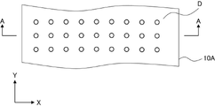
- an anisotropic light absorption film is formed using a composition containing a liquid crystal compound and a dichroic substance, and two An embodiment in which the light absorption anisotropic film has two main surfaces, and the angle formed by the normal direction of the main surface of the light absorption anisotropic film and the transmittance center axis of the light absorption anisotropic film is 0°.
- 2 is a cross-sectional view of the anisotropic light absorption film 10A
- FIG. 3 is a plan view of the anisotropic light absorption film 10A shown in FIG. 2 is a cross-sectional view taken along line A--A in FIG. In FIG.
- direction X and direction Z indicate directions of two coordinate axes orthogonal to each other on the viewing plane.
- the direction Z is parallel to the thickness direction of the light absorption anisotropic film 10A.
- direction X and direction Y indicate directions of two coordinate axes orthogonal to each other on the observation plane.
- the dichroic substance D is, as will be described later, a substance that produces a difference in absorption intensity when irradiated with two linearly polarized light beams whose electric vector directions are different by 90°.
- the two main surfaces refer to a pair of surfaces having the largest area in the anisotropic light absorption film.
- the dichroic substance D is arranged so that the angle formed by the major axis direction of the dichroic substance D with the normal line direction of the main surface of the light absorption anisotropic film 10A is 0°. . Therefore, in the light absorption anisotropic film 10A, the transmittance central axis corresponds to the direction of the black arrow in FIG. is 0°. The transmittance central axis of the light absorption anisotropic film 10A also corresponds to the direction in which the dichroic substance D is arranged.
- the transmittance center axis of the light absorption anisotropic film 10A also corresponds to the direction in which the long axis direction of the dichroic substance D is oriented. Therefore, the transmittance central axis of the light absorption anisotropic film 10A can also be said to be the absorption axis of the light absorption anisotropic film 10A.
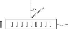
- the light absorption anisotropic film 10A satisfies the following requirement A1.
- Requirement A1 The degree of polarization measured by entering light with a wavelength of 450 nm from a direction tilted 50° with respect to the normal direction of the main surface of the light absorption anisotropic film 10A, and 50° with respect to the normal direction.
- A is 0.80 or more
- a retardation at a wavelength of 650 nm in a direction inclined by 50° with respect to the normal direction is less than 250 nm.
- FIG. 4 is a cross-sectional view of the anisotropic light absorption film 10A.
- the major axis direction of the dichroic substance D is the direction of the anisotropic light absorption film 10A.
- the angle formed by the normal to the main surface is 0°, and the angle formed by the normal to the main surface of the light absorption anisotropic film 10A and the transmittance central axis (black arrow) is 0°.
- the requirement A1 as shown in FIG.
- a light with a wavelength of 450 nm is incident from an inclined direction (white arrow in FIG. 4) to measure the degree of polarization.
- light with a wavelength of 450 nm is incident from a direction in which the angle ⁇ a formed by the normal direction in FIG. 4 and the incident direction of light is 50°, and the degree of polarization is measured.
- the degree of polarization is measured using AxoScan OPMF-1 (manufactured by Optoscience).
- the degree of polarization is a value represented by the following formula, and its maximum value is 1.00.
- Ty0 is the transmittance for polarized light in the direction orthogonal to the direction obtained by orthogonally projecting the transmittance center axis onto a plane orthogonal to the direction of light incidence
- Tz0 is the transmittance orthogonal to the direction of light incidence. It is the transmittance for polarized light in the direction parallel to the direction obtained by orthographically projecting the transmittance central axis onto the plane where
- the degree of polarization is measured using light with a wavelength of 550 nm instead of the light with a wavelength of 450 nm. Furthermore, the degree of polarization is measured using light with a wavelength of 650 nm instead of the light with a wavelength of 450 nm.
- the degree of polarization measured by entering light with a wavelength of 450 nm obtained above, the degree of polarization measured by entering light with a wavelength of 550 nm, and the degree of polarization measured by entering light with a wavelength of 650 nm.
- An average degree of polarization A is obtained by arithmetic averaging.
- the average degree of polarization A of the light absorption anisotropic film 10A is 0.80 or more, and the image derived from the image display device reflected on the peripheral members arranged around the image display device including the light absorption anisotropic film 0.85 or more is preferable, and more than 0.90 is more preferable in terms of being able to further suppress reddishness (hereinafter also simply referred to as "the point at which the effects of the present invention are more excellent").
- the average degree of polarization A is more than 0.90
- the light absorption anisotropic film 10A satisfies the following requirement A4.
- Requirement A4 The average degree of polarization A is greater than 0.90.
- the upper limit of the average degree of polarization A is not particularly limited, it may be 1.00.
- the retardation at a wavelength of 650 nm in a direction inclined by 50° with respect to the normal direction of the main surface of the light absorption anisotropic film 10A is less than 250 nm. It is preferably 230 nm or less, more preferably 230 nm or less. Although the lower limit is not particularly limited, it is often 100 nm or more, and more often 150 nm or more.
- the above retardation corresponds to the retardation measured by applying light with a wavelength of 650 nm from the direction of the white arrow shown in FIG. 4 (the direction where ⁇ a is 50°). The retardation can be measured using AxoScan OPMF-1 (manufactured by Optoscience).
- the above retardation is orthogonal to the direction in which the light travels in the anisotropic light absorption film 10A when the light is incident from a direction inclined by 50° with respect to the normal direction of the main surface of the anisotropic light absorption film 10A. It is a numerical value obtained by multiplying the in-plane retardation on the plane where the light passes through by the length along which the light travels in the light absorption anisotropic film 10A.
- the retardation at a wavelength of 550 nm is less than 220 nm in a direction inclined 50° with respect to the normal direction of the main surface of the light absorption anisotropic film 10A.
- the retardation at a wavelength of 550 nm in a direction inclined by 50° with respect to the normal direction of the main surface of the light absorption anisotropic film 10A is preferably 170 nm or less, since the effect of the present invention is more excellent.
- the lower limit of the retardation is not particularly limited, it is often 50 nm or more, and more often 70 nm or more.
- the method for measuring the retardation at a wavelength of 550 nm is carried out by changing the wavelength from the wavelength of 650 nm to the wavelength of 550 nm in the method of measuring the retardation at the wavelength of 650 nm, which is carried out under the above requirement A1.
- the anisotropic light absorption film 10A which is the first embodiment of the anisotropic light absorption film, preferably satisfies the following requirement A3 from the viewpoint that the effects of the present invention are more excellent.
- Requirement A3 Light with a wavelength of 450 to 750 nm is incident from a direction inclined by 50° with respect to the normal direction of the main surface of the light absorption anisotropic film 10A, and the degree of polarization is measured, and the degree of polarization on the longest wavelength side is measured.
- Pmax is a wavelength exceeding 610 nm, where Pmax is the wavelength showing the maximum value of .
- the above Pmax is positioned within a range of wavelengths greater than 610 nm and wavelengths of 750 nm or less.
- the degree of polarization can be measured using AxoScan OPMF-1 (manufactured by Optoscience).
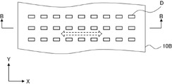
- an anisotropic light absorption film is formed using a composition containing a liquid crystal compound and a dichroic substance, wherein the two anisotropic light absorption films face each other. and an angle between the normal direction of the main surface of the anisotropic light absorption film and the central axis of transmittance of the anisotropic light absorption film is more than 0° and 45° or less.
- 5 is a cross-sectional view of the anisotropic light absorption film 10B
- FIG. 6 is a plan view of the anisotropic light absorption film 10B shown in FIG. 5 is a cross-sectional view taken along line B--B in FIG. In FIG.
- direction X and direction Z indicate directions of two coordinate axes orthogonal to each other on the viewing plane.
- the direction Z is parallel to the thickness direction of the light absorption anisotropic film 10B.
- direction X and direction Y indicate directions of two coordinate axes orthogonal to each other on the observation plane.
- the long axis direction of the dichroic substance D is arranged with being inclined with respect to the main surface of the light absorption anisotropic film 10B. More specifically, the direction of projection of the major axis direction of the dichroic substance D shown in FIGS. there is Therefore, the X-axis direction (horizontal direction of the paper surface) corresponds to the direction in which the transmittance for linearly polarized light is lowest in the in-plane direction of the light absorption anisotropic film 10B. That is, the direction of the outline dashed arrow (horizontal direction of the paper surface) shown in FIG. 6 corresponds to the azimuth angle at which the transmittance center axis is tilted. As shown in FIG.
- the dichroic substance D in the anisotropic light absorption film 10B is inclined at ⁇ b° with respect to the normal direction of the anisotropic light absorption film 10B. Therefore, the transmittance central axis of the light absorption anisotropic film 10B is parallel to the X direction and is located in a direction inclined by ⁇ b° with respect to the normal to the main surface of the light absorption anisotropic film 10B. there is Therefore, in the light absorption anisotropic film 10B, the transmittance center axis corresponds to the direction of the black arrow in FIG. is ⁇ b°. In the light absorption anisotropic film 10B, ⁇ b° is in the range of more than 0° and 45° or less.
- the light absorption anisotropic film 10B satisfies the following requirement B1.
- Requirement B1 The degree of polarization measured by entering light with a wavelength of 450 nm from a direction inclined 50° to the normal direction side with respect to the transmittance central axis of the light absorption anisotropic film 10B, and the transmittance central axis
- the degree of polarization measured by entering light with a wavelength of 550 nm from a direction tilted 50° to the normal direction side and the degree of polarization of 650 nm wavelength
- the average degree of polarization B with respect to the degree of polarization measured by incident light is 0.80 or more
- a retardation at a wavelength of 650 nm in a direction inclined 50° to the normal direction with respect to the transmittance central axis is less than 250 nm.
- FIG. 7 is a perspective view of the anisotropic light absorption film 10B.
- the major axis direction of the dichroic substance D is the direction of the anisotropic light absorption film 10B.
- the angle between the normal to the main surface is ⁇ b°, and the angle between the normal to the main surface of the anisotropic light absorption film 10A and the transmittance central axis (black arrow) is ⁇ b°.
- a direction inclined 50° to the normal direction side with respect to the transmittance center axis of the light absorption anisotropic film 10B indicated by the black arrow (white outline in FIG. 7)
- the degree of polarization is measured by entering light with a wavelength of 450 nm from the arrow). That is, the degree of polarization is measured by irradiating light with a wavelength of 450 nm from the direction where the angle ⁇ c formed by the transmittance center axis and the incident direction of light indicated by the black arrow in FIG. 7 is 50°.
- the transmittance center axis, the normal direction of the main surface of the light absorption anisotropic film 10B, and the incident direction of light are located on the same plane.
- the degree of polarization is measured using AxoScan OPMF-1 (manufactured by Optoscience). The definition of the degree of polarization is as described above.
- the degree of polarization is measured using light with a wavelength of 550 nm instead of the light with a wavelength of 450 nm. Furthermore, the degree of polarization is measured using light with a wavelength of 650 nm instead of the light with a wavelength of 450 nm.
- the degree of polarization measured by incident light with a wavelength of 450 nm obtained above, the degree of polarization measured by incident light with a wavelength of 550 nm, and the degree of polarization measured by incident light with a wavelength of 650 nm.
- An average degree of polarization B is obtained by arithmetic averaging.
- the average degree of polarization B of the light-absorbing anisotropic film 10B is 0.80 or more, preferably 0.85 or more, and more preferably more than 0.90, from the viewpoint that the effects of the present invention are more excellent.
- the average degree of polarization B is more than 0.90, the light absorption anisotropic film 10B satisfies the following requirement B4.
- Requirement B4 The average degree of polarization B is greater than 0.90.
- the upper limit of the average degree of polarization B is not particularly limited, 1.00 can be mentioned.
- the retardation at a wavelength of 650 nm in the direction inclined 50° to the normal direction with respect to the transmittance central axis of the light absorption anisotropic film 10B is less than 250 nm, and the effect of the present invention is more excellent. 240 nm or less is preferable, and 230 nm or less is more preferable. Although the lower limit is not particularly limited, it is often 100 nm or more, and more often 150 nm or more.
- the above retardation corresponds to the retardation measured by applying light with a wavelength of 650 nm from the direction of the white arrow shown in FIG. The retardation can be measured using AxoScan OPMF-1 (manufactured by Optoscience).
- Requirement B2 The retardation at a wavelength of 550 nm is less than 220 nm in a direction tilted 50° from the direction normal to the transmittance center axis of the anisotropic light absorption film 10B.
- the retardation at a wavelength of 550 nm in a direction inclined 50° to the normal direction side with respect to the transmittance central axis of the light absorption anisotropic film 10B is preferably 170 nm or less in terms of more excellent effects of the present invention.
- the lower limit of the retardation is not particularly limited, it is often 50 nm or more, and more often 70 nm or more.
- the method for measuring the retardation at a wavelength of 550 nm is carried out by changing the wavelength from the wavelength of 650 nm to the wavelength of 550 nm in the method for measuring the retardation at the wavelength of 650 nm, which is carried out under the above requirement B1.
- the anisotropic light absorption film 10B which is the second embodiment of the anisotropic light absorption film, preferably satisfies the following requirement B3 in order to obtain a more excellent effect of the present invention.
- Requirement B3 Light with a wavelength of 450 to 750 nm is incident from a direction tilted 50° in the normal direction with respect to the transmittance central axis of the light absorption anisotropic film 10B, and the degree of polarization is measured, and the degree of polarization is measured on the longest wavelength side.
- Pmax is a wavelength exceeding 610 nm, where Pmax is the wavelength at which a certain degree of polarization exhibits a maximum value.
- the above Pmax is positioned within a range of wavelengths greater than 610 nm and wavelengths of 750 nm or less.
- the degree of polarization can be measured using AxoScan OPMF-1 (manufactured by Optoscience).
- Techniques for aligning the dichroic substance D in a desired orientation include a technique for producing a polarizer using the dichroic substance D and a technique for producing a guest-host liquid crystal cell.
- a technique for producing a dichroic polarizing element described in JP-A-11-305036 and JP-A-2002-090526, and the guests described in JP-A-2002-099388 and JP-A-2016-027387 The technique used in the manufacturing method of the host-type liquid crystal display device can also be used in manufacturing the light absorption anisotropic film.
- the orientation of the dichroic substance D by forming chemical bonds.
- the orientation can be fixed by proceeding with the polymerization of the host liquid crystal, the dichroic substance, or the optionally added polymerizable component.
- the light absorption anisotropic film may be a layer formed by fixing a liquid crystal compound forming a smectic phase or a nematic phase.
- a light absorption anisotropic film can also be produced by permeating a dichroic substance into a polymer film and orienting the dichroic substance along the orientation of the polymer molecules in the polymer film.
- the thickness of the light absorption anisotropic film is not particularly limited, it is preferably 1 to 7 ⁇ m, more preferably 1.5 to 5 ⁇ m, from the viewpoint that the effects of the present invention are more excellent.
- a dichroic substance means a dye whose absorbance differs depending on the direction.
- the dichroic substance may be fixed by polymerization in the light absorption anisotropic film.
- the dichroic substance is not particularly limited, and includes visible light absorbing substances (dichroic dyes), luminescent substances (fluorescent substances, phosphorescent substances), ultraviolet absorbing substances, infrared absorbing substances, nonlinear optical substances, carbon nanotubes, and inorganic Substances (for example, quantum rods) can be used, and conventionally known dichroic substances (preferably, dichroic dyes) can be used.
- a dichroic azo dye compound As the dichroic substance, a dichroic azo dye compound is preferred.
- a dichroic azo dye compound means an azo dye compound having different absorbance depending on the direction.
- the dichroic azo dye compound may or may not exhibit liquid crystallinity. When the dichroic azo dye compound exhibits liquid crystallinity, it may exhibit nematicity or smecticity.
- the temperature range showing the liquid crystal phase is preferably room temperature (approximately 20 to 28°C) to 300°C, and more preferably 50 to 200°C in terms of handleability and production suitability.
- At least one dye compound having a maximum absorption wavelength in the wavelength range of 560 to 700 nm (hereinafter also abbreviated as “first dichroic azo dye compound”), It is preferable to use at least one dye compound having a maximum absorption wavelength in the wavelength range of 455 nm or more and less than 560 nm (hereinafter also abbreviated as “second dichroic azo dye compound”).
- first dichroic azo dye compound At least one dye compound having a maximum absorption wavelength in the wavelength range of 455 nm or more and less than 560 nm.
- second dichroic azo dye compound More preferably, at least a dichroic azo dye compound represented by formula (1) described later and a dichroic azo dye compound represented by formula (2) described later are used.
- dichroic azo dye compounds may be used in combination.
- dichroic azo dye compound and at least one dye compound having a maximum absorption wavelength in the wavelength range of 380 nm or more and less than 455 nm (hereinafter also abbreviated as "third dichroic azo dye compound”). is preferred.
- the dichroic azo dye compound preferably has a crosslinkable group.
- crosslinkable groups include (meth)acryloyl groups, epoxy groups, oxetanyl groups, and styryl groups, with (meth)acryloyl groups being preferred.
- the first dichroic azo dye compound is preferably a compound having a chromophore as a nucleus and a side chain bonded to the terminal of the chromophore.
- chromophores include aromatic ring groups (e.g., aromatic hydrocarbon groups, aromatic heterocyclic groups), azo groups, and the like, and a structure having both an aromatic ring group and an azo group A bisazo structure having an aromatic heterocyclic group (preferably a thienothiazole group) and two azo groups is more preferred.
- the side chain is not particularly limited, and includes groups represented by R1, R2 or R3 in formula (1) described below.
- the first dichroic azo dye compound is a dichroic azo dye compound having a maximum absorption wavelength in the wavelength range of 560 to 700 nm. and more preferably a dichroic azo dye compound having a maximum absorption wavelength in the range of 560 to 640 nm.
- the maximum absorption wavelength (nm) of the dichroic azo dye compound in the present specification is a solution of the dichroic azo dye compound dissolved in a good solvent, and is measured with a spectrophotometer at a wavelength of 380 to 800 nm. It is determined from the UV-visible spectrum in the range.
- the first dichroic azo dye compound is preferably a compound represented by the following formula (1) from the viewpoint of further improving the polarization degree of the light absorption anisotropic film.
- Ar1 and Ar2 each independently represent an optionally substituted phenylene group or an optionally substituted naphthylene group, preferably a phenylene group.
- R1 is a hydrogen atom, an optionally substituted linear or branched alkyl group having 1 to 20 carbon atoms, an alkoxy group, an alkylthio group, an alkylsulfonyl group, an alkylcarbonyl groups, alkyloxycarbonyl groups, acyloxy groups, alkylcarbonate groups, alkylamino groups, acylamino groups, alkylcarbonylamino groups, alkoxycarbonylamino groups, alkylsulfonylamino groups, alkylsulfamoyl groups, alkylcarbamoyl groups, alkylsulfinyl groups, It represents an alkylureido group, an alkylphosphoamide group, an alkylimino group, or an alkylsilyl group.
- R1 is a group other than a hydrogen atom
- R1' represents a hydrogen atom or a linear or branched alkyl group having 1 to 6 carbon atoms. In each group, when a plurality of R1' are present, they may be the same or different.
- R2 and R3 are groups other than hydrogen atoms
- R2' represents a hydrogen atom or a linear or branched alkyl group having 1 to 6 carbon atoms. In each group, when a plurality of R2' are present, they may be the same or different.
- R2 and R3 may combine with each other to form a ring, or R2 or R3 may combine with Ar2 to form a ring.
- R1 is preferably an electron-withdrawing group
- R2 and R3 are preferably groups with low electron-donating properties.
- Specific examples of such groups for R1 include an alkylsulfonyl group, an alkylcarbonyl group, an alkyloxycarbonyl group, an acyloxy group, an alkylsulfonylamino group, an alkylsulfamoyl group, an alkylsulfinyl group, an alkylureido group, and the like.
- R2 and R3 include groups having the following structures. The group having the structure below is shown in the above formula (1) in a form containing a nitrogen atom to which R2 and R3 are bonded.
- the second dichroic azo dye compound is a different compound from the first dichroic azo dye compound, and specifically has a different chemical structure.
- the second dichroic azo dye compound is preferably a compound having a chromophore that is the nucleus of the dichroic azo dye compound and a side chain that binds to the terminal of the chromophore.
- Specific examples of the chromophore include aromatic ring groups (e.g., aromatic hydrocarbon groups, aromatic heterocyclic groups), azo groups and the like, and structures having both aromatic hydrocarbon groups and azo groups are preferred. , a bisazo or trisazo structure having an aromatic hydrocarbon group and two or three azo groups is more preferred.
- the side chain is not particularly limited, and includes groups represented by R4, R5 or R6 in formula (2) described below.
- the second dichroic azo dye compound is a dichroic azo dye compound having a maximum absorption wavelength in the range of wavelength 455 nm or more and less than 560 nm.
- a dichroic azo dye compound having a maximum absorption wavelength in the range of 555 nm is preferable, and a dichroic azo dye compound having a maximum absorption wavelength in the wavelength range of 455 to 550 nm is more preferable.
- the second dichroic azo dye compound is preferably a compound represented by the formula (2) from the viewpoint of further improving the degree of polarization of the light absorption anisotropic film.
- n 1 or 2.
- Ar3, Ar4 and Ar5 are each independently a phenylene group optionally having substituent(s), a naphthylene group optionally having substituent(s) or a heterocyclic group optionally having substituent(s) represents a cyclic group.
- Heterocyclic groups can be either aromatic or non-aromatic. Atoms other than carbon constituting the aromatic heterocyclic group include a nitrogen atom, a sulfur atom and an oxygen atom. When the aromatic heterocyclic group has a plurality of non-carbon ring-constituting atoms, these may be the same or different.
- aromatic heterocyclic groups include, for example, pyridylene group (pyridine-diyl group), pyridazine-diyl group, imidazole-diyl group, thienylene (thiophene-diyl group), quinolylene group (quinoline-diyl group), and isoquinolylene.
- R4 is the same as that of R1 in formula (1).
- definitions of R5 and R6 are the same as those of R2 and R3 in formula (1).
- R4 is preferably an electron-withdrawing group
- R5 and R6 are preferably groups with low electron-donating properties.
- specific examples in which R4 is an electron-withdrawing group are the same as specific examples in which R1 is an electron-withdrawing group
- R5 and R6 are groups with low electron-donating properties.
- Specific examples in the case of are the same as specific examples in the case where R2 and R3 are groups with low electron donating properties.
- the logP value is an index that expresses the hydrophilic and hydrophobic properties of a chemical structure.
- the absolute value of the difference between the logP value of the side chain of the first dichroic azo dye compound and the logP value of the side chain of the second dichroic azo dye compound (hereinafter also referred to as "logP difference"). is preferably 2.30 or less, more preferably 2.0 or less, still more preferably 1.5 or less, and particularly preferably 1.0 or less. If the logP difference is 2.30 or less, the affinity between the first dichroic azo dye compound and the second dichroic azo dye compound increases, making it easier to form an array structure. The degree of polarization of the anisotropic film is further improved.
- the side chain of the first dichroic azo dye compound and the second dichroic azo dye compound means a group bonded to the end of the chromophore described above.
- the first dichroic azo dye compound is a compound represented by formula (1)
- R1, R2 and R3 in formula (1) are side chains
- the second dichroic azo dye When the compound is represented by formula (2), R4, R5 and R6 in formula (2) are side chains.
- R1 and R4 at least one of the logP value difference between R1 and R5, the logP value difference between R2 and R4, and the logP value difference between R2 and R5 preferably fulfilled.
- the logP value is an index that expresses the hydrophilicity and hydrophobicity of a chemical structure, and is sometimes called the hydrophilicity/hydrophobicity parameter.
- LogP values can be calculated using software such as ChemBioDraw Ultra or HSPiP (Ver.4.1.07). Also, OECD Guidelines for the Testing of Chemicals, Sections 1, Test No. It can also be obtained experimentally by the method of 117 or the like. In the present invention, unless otherwise specified, the value calculated by inputting the structural formula of the compound into HSPiP (Ver.4.1.07) is employed as the logP value.
- the third dichroic azo dye compound is a dichroic azo dye compound other than the first dichroic azo dye compound and the second dichroic azo dye compound, specifically, the first dichroic azo dye compound
- the chemical structure is different from that of the chromatic azo dye compound and the second dichroic azo dye compound.
- the light absorption anisotropic film contains the third dichroic azo dye compound, there is an advantage that the color of the light absorption anisotropic film can be easily adjusted.
- the maximum absorption wavelength of the third dichroic azo dye compound is 380 nm or more and less than 455 nm, preferably 385 to 454 nm.
- a dichroic azo dye represented by the following formula (6) is preferable as the third dichroic azo dye compound.
- a and B each independently represent a crosslinkable group.
- a and b each independently represent 0 or 1. Both a and b are preferably 0 in terms of excellent polarization degree at a wavelength of 420 nm.
- L2 represents a monovalent substituent
- L2 represents a single bond or a divalent linking group.
- Ar 1 represents a (n1+2)-valent aromatic hydrocarbon group or heterocyclic group
- Ar 2 represents a (n2+2)-valent aromatic hydrocarbon group or heterocyclic group
- Ar 3 represents ( represents an n3+2)-valent aromatic hydrocarbon group or heterocyclic group
- R 1 , R 2 and R 3 each independently represent a monovalent substituent.
- n1 ⁇ 2 the plurality of R1 may be the same or different
- n2 ⁇ 2 the plurality of R2 may be the same or different
- n3 ⁇ 2. may be the same or different from each other.
- k represents an integer of 1-4.
- Examples of the crosslinkable groups represented by A and B in formula (6) include polymerizable groups described in paragraphs [0040] to [0050] of JP-A-2010-244038.
- an acryloyl group, a methacryloyl group, an epoxy group, an oxetanyl group, and a styryl group are preferable from the viewpoint of improving reactivity and synthesis suitability, and an acryloyl group and a methacryloyl group are preferable from the viewpoint that the solubility can be further improved. more preferred.
- L2 represents a monovalent substituent
- L2 represents a single bond or a divalent linking group
- the monovalent substituent represented by L 1 and L 2 includes a group introduced to increase the solubility of the dichroic substance, or an electron-donating and electron-donating group introduced to adjust the color tone of the dye. Groups with attractive properties are preferred. Examples of substituents include alkyl groups, alkenyl groups, alkynyl groups, aryl groups, substituted or unsubstituted amino groups, alkoxy groups, oxycarbonyl groups, acyloxy groups, acylamino groups, alkoxycarbonylamino groups, and aryloxycarbonylamino groups.
- sulfonylamino group sulfamoyl group, carbamoyl group, alkylthio group, arylthio group, sulfonyl group, sulfinyl group, ureido group, phosphoramide group, heterocyclic group, silyl group, halogen atom, hydroxy group, mercapto group, cyano group, Nitro group, hydroxamic acid group, sulfino group, hydrazino group, imino group, azo group and the like. These substituents may be further substituted by these substituents. Moreover, when it has two or more substituents, they may be the same or different.
- R B (OR A ) na — groups, which are groups in which an alkoxy group is substituted with an alkyl group.
- R A represents an alkylene group having 1 to 5 carbon atoms
- R B represents an alkyl group having 1 to 5 carbon atoms
- na is 1 to 10 (preferably 1 to 5, more preferably 1 to 3) represents an integer.
- monovalent substituents represented by L 1 and L 2 include alkyl groups, alkenyl groups, alkoxy groups, and groups in which these groups are further substituted with these groups (for example, R B —(OR A ) na — group) is preferred, and alkyl groups, alkoxy groups, and groups in which these groups are further substituted with these groups (for example, R B —(OR A ) na described above) are preferred.
- - group is more preferred.
- Examples of divalent linking groups represented by L 1 and L 2 include -O-, -S-, -CO-, -COO-, -O-CO-O-, -CO-NR N -, -O —CO—NR N —, —NR N —CO—NR N —, —SO 2 —, —SO—, an alkylene group, a cycloalkylene group, an alkenylene group, and groups in which two or more of these groups are combined etc.
- RN represents a hydrogen atom or an alkyl group. When there are multiple RNs , the multiple RNs may be the same or different.
- the number of atoms in the main chain of at least one of L 1 and L 2 is preferably 3 or more, more preferably 5 or more. Preferably, the number is 7 or more, and particularly preferably 10 or more.
- the upper limit of the number of atoms in the main chain is preferably 20 or less, more preferably 12 or less.
- the number of atoms in the main chain of at least one of L 1 and L 2 is preferably 1 to 5 from the viewpoint of further improving the polarization degree of the light absorption anisotropic film.
- the “main chain” in L 1 means the “O” atom that connects L 1 and “A”, It refers to a moiety, and "the number of atoms in the main chain” refers to the number of atoms constituting the moiety.
- the “main chain” in L 2 means the “O” atom that connects L 2 and “B”.
- the number of atoms in the main chain refers to the number of atoms constituting the moiety.
- the “number of atoms in the main chain” does not include the number of branched chain atoms, which will be described later.
- the number of atoms in the main chain in L1 means the number of atoms in L1 that does not contain branched chains.
- the " number of atoms in the main chain” in L2 refers to the number of atoms in L2 not including branched chains.
- the number of atoms in the main chain of L 1 is 5 (the number of atoms in the dotted frame on the left side of the following formula (D1))
- the main chain of L 2 The number of atoms of is 5 (the number of atoms in the dotted frame on the right side of formula (D1) below).
- the number of atoms in the main chain of L 1 is 7 (the number of atoms in the dotted frame on the left side of the formula (D10) below), and the number of atoms in the main chain of L 2 is The number is 5 (the number of atoms in the dotted frame on the right side of formula (D10) below).
- L 1 and L 2 may have a branched chain.
- the “branched chain” in L 1 means that the “O” atom that connects L 1 in formula (6) and “A” are directly connected. It means the part other than the part necessary for
- the “branched chain” in L 2 means that the “O” atom that connects L 2 in formula (6) and “B” are directly connected It means the part other than the part necessary for
- the “branched chain” in L 1 means the longest atomic chain extending from the “O” atom connected to L 1 in formula (6) (that is, the main chain).
- the “branched chain” in L2 means the longest atomic chain extending from the “O” atom connecting L2 in formula (6) (i.e. main chain).
- the number of atoms in the branched chain is preferably 3 or less. When the number of branched chain atoms is 3 or less, there is an advantage that the degree of polarization of the light absorption anisotropic film is further improved.
- the number of branched chain atoms does not include the number of hydrogen atoms.
- Ar 1 is (n1+2)-valent (e.g., trivalent when n1 is 1)
- Ar 2 is (n2+2)-valent (e.g., trivalent when n2 is 1)
- Ar 3 represents an (n3+2)-valent (for example, trivalent when n3 is 1) aromatic hydrocarbon group or heterocyclic group.
- each of Ar 1 to Ar 3 can be rephrased as a divalent aromatic hydrocarbon group or divalent heterocyclic group substituted with n1 to n3 substituents (R 1 to R 3 described later).
- the divalent aromatic hydrocarbon group represented by Ar 1 to Ar 3 may be monocyclic or have a condensed ring structure of two or more rings.
- the ring number of the divalent aromatic hydrocarbon group is preferably 1 to 4, more preferably 1 to 2, and even more preferably 1 (that is, a phenylene group) from the viewpoint of further improving the solubility.
- Specific examples of the divalent aromatic hydrocarbon group include a phenylene group, an azulene-diyl group, a naphthylene group, a fluorene-diyl group, anthracene-diyl group and a tetracene-diyl group, which further improve the solubility. From this point of view, a phenylene group and a naphthylene group are preferable, and a phenylene group is more preferable.
- the third dichroic azo dye compound preferably does not have a radically polymerizable group in terms of excellent polarization degree at 420 nm.
- the third dichroic azo dye compound is more preferably a dichroic substance having a structure represented by the following formula (1-1) in that the degree of polarization of the light absorption anisotropic film is further improved. preferable.
- R 1 , R 3 , R 4 , R 5 , n1, n3, L 1 and L 2 are defined respectively as R 1 , R 3 , R 4 and R 5 in formula (1) , n1, n3 , L1 and L2.
- definitions of R 21 and R 22 are independently the same as R 2 in formula (1).
- definitions of n21 and n22 are each independently synonymous with n2 in formula (1). n1+n21+n22+n3 ⁇ 1, and n1+n21+n22+n3 is preferably 1-9, more preferably 1-5.
- the content of the dichroic substance in the light absorption anisotropic film is not particularly limited. is preferably 15% by mass or more, more preferably 30% by mass or more. Although the upper limit of the content is not particularly limited, it is often 45% by mass or less, more often 35% by mass or less.
- the content of the first dichroic azo dye compound is preferably 40 to 90 parts by mass, preferably 45 to 75 parts by mass, with respect to 100 parts by mass of the total content of the dichroic substance in the light absorption anisotropic film. is more preferred.
- the content of the second dichroic azo dye compound is preferably 6 to 50 parts by mass, preferably 8 to 35 parts by mass, with respect to 100 parts by mass of the total dichroic substance content in the light absorption anisotropic film.
- the content of the third dichroic azo dye compound is preferably 3 to 35 parts by mass, preferably 5 to 35 parts by mass, with respect to 100 mass parts of the dichroic azo dye compound in the light absorption anisotropic film. is more preferred.
- the content ratio of the first dichroic azo dye compound, the second dichroic azo dye compound, and the optionally used third dichroic azo dye compound is the light absorption anisotropy It can be arbitrarily set in order to adjust the tint of the film.
- the content ratio of the second dichroic azo dye compound to the first dichroic azo dye compound is in terms of moles , is preferably 0.1 to 10, more preferably 0.2 to 5, and particularly preferably 0.3 to 0.8. If the content ratio of the second dichroic azo dye compound to the first dichroic azo dye compound is within the above range, the degree of polarization is enhanced.
- the light absorption anisotropic film preferably contains a liquid crystal compound. This makes it possible to orient the dichroic substance with a higher degree of orientation while suppressing precipitation of the dichroic substance.
- a liquid crystal compound both a polymer liquid crystal compound and a low-molecular liquid crystal compound can be used, and a polymer liquid crystal compound is preferable because the degree of orientation can be increased.
- a high-molecular liquid crystal compound and a low-molecular liquid crystal compound may be used in combination.
- the term "polymeric liquid crystal compound” refers to a liquid crystal compound having repeating units in its chemical structure.
- low-molecular-weight liquid crystal compound refers to a liquid crystal compound having no repeating unit in its chemical structure.
- polymer liquid crystal compound examples include thermotropic liquid crystalline polymers described in JP-A-2011-237513, and high molecular weight compounds described in paragraphs [0012] to [0042] of International Publication No. 2018/199096. Examples include molecular liquid crystal compounds.
- low-molecular-weight liquid crystal compounds include liquid crystal compounds described in paragraphs [0072] to [0088] of JP-A-2013-228706, among which liquid crystal compounds exhibiting smectic properties are preferred.
- the liquid crystal compound is a polymer liquid crystal compound containing a repeating unit represented by the following formula (1) (hereinafter also abbreviated as “repeating unit (1)”), since the orientation degree of the dichroic substance is higher.
- repeating unit (1) a repeating unit represented by the following formula (1) (hereinafter also abbreviated as “repeating unit (1)”), since the orientation degree of the dichroic substance is higher.
- P1 represents the main chain of the repeating unit
- L1 represents a single bond or a divalent linking group
- SP1 represents a spacer group
- M1 represents a mesogenic group
- T1 represents a terminal group.
- Examples of the main chain of the repeating unit represented by P1 include groups represented by the following formulas (P1-A) to (P1-D).
- a group represented by the following formula (P1-A) is preferable in terms of easiness.
- R 1 , R 2 , R 3 and R 4 are each independently a hydrogen atom, a halogen atom, a cyano group, an alkyl group having 1 to 10 carbon atoms, Alternatively, it represents an alkoxy group having 1 to 10 carbon atoms.
- the alkyl group may be a linear or branched alkyl group, or may be an alkyl group having a cyclic structure (cycloalkyl group).
- the number of carbon atoms in the alkyl group is preferably 1 to 5.
- the group represented by the above formula (P1-A) is preferably one unit of the partial structure of the poly(meth)acrylic acid ester obtained by polymerization of the (meth)acrylic acid ester.
- the group represented by the above formula (P1-B) is preferably an ethylene glycol unit formed by ring-opening polymerization of an epoxy group of a compound having an epoxy group.
- the group represented by the above formula (P1-C) is preferably a propylene glycol unit formed by ring-opening polymerization of an oxetane group of a compound having an oxetane group.
- the group represented by formula (P1-D) is preferably a siloxane unit of polysiloxane obtained by condensation polymerization of a compound having at least one of an alkoxysilyl group and a silanol group.
- the compound having at least one of an alkoxysilyl group and a silanol group includes a compound having a group represented by the formula SiR 14 (OR 15 ) 2 —.
- R 14 has the same definition as R 14 in (P1-D), and each of a plurality of R 15 independently represents a hydrogen atom or an alkyl group having 1 to 10 carbon atoms.
- L1 is a single bond or a divalent linking group.
- Divalent linking groups represented by L1 include -C(O)O-, -O-, -S-, -C(O)NR 3 -, -SO 2 -, and -NR 3 R 4 - is mentioned.
- R 3 and R 4 each independently represent a hydrogen atom or an optionally substituted alkyl group having 1 to 6 carbon atoms.
- P1 is a group represented by formula (P1-A)
- L1 is preferably a group represented by -C(O)O-, since the degree of orientation of the dichroic substance is higher.
- P1 is a group represented by formulas (P1-B) to (P1-D)
- L1 is preferably a single bond because the dichroic substance has a higher degree of orientation.
- the spacer group represented by SP1 is composed of an oxyethylene structure, an oxypropylene structure, a polysiloxane structure and an alkylene fluoride structure in view of the ease of exhibiting liquid crystallinity and the availability of raw materials. It preferably contains at least one structure selected from the group.
- the oxyethylene structure represented by SP1 is preferably a group represented by *--(CH 2 --CH 2 O) n1 --*.
- n1 represents an integer of 1 to 20
- * represents the bonding position with L1 or M1 in the above formula (1).
- n1 is preferably an integer of 2 to 10, more preferably an integer of 2 to 4, and even more preferably 3, in order to increase the degree of orientation of the dichroic substance.
- the oxypropylene structure represented by SP1 is preferably a group represented by *-(CH(CH 3 )-CH 2 O) n2 --*, since the degree of orientation of the dichroic substance is higher.
- n2 represents an integer of 1 to 3
- * represents the bonding position with L1 or M1.
- the polysiloxane structure represented by SP1 is preferably a group represented by *-(Si(CH 3 ) 2 -O) n3 -* because the degree of orientation of the dichroic substance is higher.
- n3 represents an integer of 6 to 10
- * represents the bonding position with L1 or M1.
- alkylene fluoride structure represented by SP1 is preferably a group represented by *-(CF 2 -CF 2 ) n4 -* from the viewpoint that the dichroic substance has a higher degree of orientation.
- n4 represents an integer of 6 to 10
- * represents the bonding position with L1 or M1.
- the mesogenic group represented by M1 is a group showing the main skeleton of the liquid crystal molecule that contributes to liquid crystal formation.
- Liquid crystal molecules exhibit liquid crystallinity, which is an intermediate state (mesophase) between a crystalline state and an isotropic liquid state.
- the mesogenic group for example, a group having at least one cyclic structure selected from the group consisting of aromatic hydrocarbon groups, heterocyclic groups, and alicyclic groups is preferred.
- the mesogenic group preferably has an aromatic hydrocarbon group, more preferably 2 to 4 aromatic hydrocarbon groups, and 3 aromatic Group hydrocarbon groups are more preferred.
- the mesogenic group As the mesogenic group, the following formula (M1-A) or A group represented by the following formula (M1-B) is preferable, and a group represented by the formula (M1-B) is more preferable.
- A1 is a divalent group selected from the group consisting of aromatic hydrocarbon groups, heterocyclic groups and alicyclic groups. These groups may be substituted with alkyl groups, fluorinated alkyl groups, alkoxy groups or substituents.
- the divalent group represented by A1 is preferably a 4- to 6-membered ring. Also, the divalent group represented by A1 may be monocyclic or condensed. * represents the binding position with SP1 or T1.
- the divalent aromatic hydrocarbon group represented by A1 includes a phenylene group, a naphthylene group, a fluorene-diyl group, an anthracene-diyl group and a tetracene-diyl group.
- a phenylene group or a naphthylene group is preferable, and a phenylene group is more preferable, from the viewpoint of properties and the like.
- the divalent heterocyclic group represented by A1 may be either aromatic or non-aromatic, but from the viewpoint of increasing the degree of orientation of the dichroic substance, a divalent aromatic heterocyclic group Preferably.
- Atoms other than carbon constituting the divalent aromatic heterocyclic group include a nitrogen atom, a sulfur atom and an oxygen atom.
- the aromatic heterocyclic group has a plurality of non-carbon ring-constituting atoms, these may be the same or different.
- divalent aromatic heterocyclic groups include, for example, pyridylene group (pyridine-diyl group), pyridazine-diyl group, imidazole-diyl group, thienylene (thiophene-diyl group), quinolylene group (quinoline-diyl group ), isoquinolylene group (isoquinoline-diyl group), oxazole-diyl group, thiazole-diyl group, oxadiazole-diyl group, benzothiazole-diyl group, benzothiadiazole-diyl group, phthalimide-diyl group, thienothiazole-diyl group , thiazolothiazole-diyl group, thienothiophene-diyl group, and thienooxazole-diyl group.
- pyridylene group pyridine-diy
- divalent alicyclic group represented by A1 examples include a cyclopentylene group and a cyclohexylene group.
- a1 represents an integer of 1-10. When a1 is 2 or more, multiple A1s may be the same or different.
- A2 and A3 are each independently a divalent group selected from the group consisting of aromatic hydrocarbon groups, heterocyclic groups and alicyclic groups. Specific examples and preferred embodiments of A2 and A3 are the same as those of A1 in formula (M1-A), so description thereof is omitted.
- a2 represents an integer of 1 to 10, and when a2 is 2 or more, multiple A2 may be the same or different, and multiple A3 may be the same or different.
- a plurality of LA1 may be the same or different.
- a2 is preferably an integer of 2 or more, more preferably 2, because the dichroic substance has a higher degree of orientation.
- LA1 is a divalent linking group.
- each of the plurality of LA1 is independently a single bond or a divalent linking group, and at least one of the plurality of LA1 is a divalent linking group.
- a2 is 2, it is preferable that one of the two LA1s is a divalent linking group and the other is a single bond because the degree of orientation of the dichroic substance is higher.
- the terminal group represented by T1 includes a hydrogen atom, a halogen atom, a cyano group, a nitro group, a hydroxy group, an alkyl group having 1 to 10 carbon atoms, an alkoxy group having 1 to 10 carbon atoms, and an alkoxy group having 1 to 10 carbon atoms.
- 1 to 10 alkylthio group 1 to 10 carbon alkoxycarbonyloxy group, 1 to 10 carbon alkoxycarbonyl group (ROC(O)-: R is an alkyl group), 1 to 10 carbon acyloxy group, carbon 1 to 10 acylamino group, 1 to 10 carbon atoms alkoxycarbonylamino group, 1 to 10 carbon atoms sulfonylamino group, 1 to 10 carbon atoms sulfamoyl group, 1 to 10 carbon atoms carbamoyl group, 1 carbon atom 10 to 10 sulfinyl groups, ureido groups with 1 to 10 carbon atoms, and (meth)acryloyloxy group-containing groups.
- Examples of the (meth)acryloyloxy group-containing group include -LA (L represents a single bond or a linking group. Specific examples of the linking group are the same as L1 and SP1 described above. A is (meth) represents an acryloyloxy group).
- T1 is preferably an alkoxy group having 1 to 10 carbon atoms, more preferably an alkoxy group having 1 to 5 carbon atoms, and even more preferably a methoxy group, since the dichroic substance has a higher degree of orientation.
- These terminal groups may be further substituted with these groups or polymerizable groups described in JP-A-2010-244038.
- T1 is preferably a polymerizable group from the viewpoint that the adhesiveness to the adjacent layer can be improved and the cohesive force of the film can be improved.
- the polymerizable group is not particularly limited, but is preferably a polymerizable group capable of radical polymerization or cationic polymerization.
- As the radically polymerizable group generally known radically polymerizable groups can be used, and acryloyl groups and methacryloyl groups are preferred. In this case, an acryloyl group is generally known to have a high polymerization rate, and an acryloyl group is preferred from the viewpoint of improving productivity, but a methacryloyl group can also be used as the polymerizable group.
- cationically polymerizable groups generally known cationically polymerizable groups can be used. Specifically, alicyclic ether groups, cyclic acetal groups, cyclic lactone groups, cyclic thioether groups, spiroorthoester groups, and , a vinyloxy group, and the like. Among them, an alicyclic ether group or a vinyloxy group is preferable, and an epoxy group, an oxetanyl group or a vinyloxy group is preferable.
- the weight-average molecular weight (Mw) of the polymer liquid crystal compound containing the repeating unit represented by the above formula (1) is preferably 1000 to 500000, more preferably 2000 to 300000, because the degree of orientation of the dichroic substance is higher. more preferred. If the Mw of the polymer liquid crystal compound is within the above range, the polymer liquid crystal compound can be easily handled.
- the weight-average molecular weight (Mw) of the polymer liquid crystal compound is preferably 10,000 or more, more preferably 10,000 to 300,000, from the viewpoint of suppressing cracks during coating.
- the weight average molecular weight (Mw) of the polymer liquid crystal compound is preferably less than 10,000, more preferably 2,000 or more and less than 10,000, from the viewpoint of the temperature latitude of the degree of orientation.
- the weight average molecular weight and number average molecular weight in the present invention are values measured by a gel permeation chromatography (GPC) method.
- a reverse wavelength dispersion liquid crystal compound is also preferable.
- “having reverse wavelength dispersion” means that the retardation film produced using this liquid crystal compound satisfies the relationships of the following formulas (X1) and (X2). Re(450)/Re(550) ⁇ 1 (X1) 1 ⁇ Re(630)/Re(550) (X2)
- the reverse wavelength dispersion polymerizable liquid crystal compound is not particularly limited as long as it can form a reverse wavelength dispersion film, for example, represented by the general formula (I) described in JP-A-2008-297210 Compounds (especially compounds described in [0034] to [0039] paragraphs), compounds represented by the general formula (1) described in JP-A-2010-084032 (especially [0067] to [0073] paragraphs described compound), the compound represented by the general formula (1) described in JP-A-2019-73496 (especially the compound described in paragraphs [0117] to [0124]), and JP-A-2016-081035 Compounds represented by the described general formula (1) (especially compounds described in paragraphs [0043] to [0055]) can be mentioned.
- the general formula (1) described in JP-A-2008-297210 Compounds (especially compounds described in [0034] to [0039] paragraphs), compounds represented by the general formula (1) described in JP-A-2010-084032 (especially [0067] to [0073] paragraph
- a polymerizable liquid crystal compound having a partial structure represented by the following formula (II) is preferable because the effects of the present invention are more excellent.
- Ar represents any aromatic ring selected from the group consisting of groups represented by formulas (Ar-1) to (Ar-7).
- Ar-7 represents the bonding position with D 1 or D 2 , and explanation of the symbols in the following formulas (Ar-1) to (Ar-7). is the same as that described for Ar in formula (III) described later.
- a polymerizable liquid crystal compound represented by the following formula (III) is preferable.
- a polymerizable liquid crystal compound represented by the following formula (III) is a compound exhibiting liquid crystallinity.
- G 1 and G 2 each independently represent a divalent alicyclic hydrocarbon group having 5 to 8 carbon atoms or an aromatic hydrocarbon group, and the methylene group contained in the alicyclic hydrocarbon group is , —O—, —S—, or —NH—.
- L 1 and L 2 each independently represent a monovalent organic group, and at least one selected from the group consisting of L 1 and L 2 represents a monovalent group having a polymerizable group.
- Ar represents any aromatic ring selected from the group consisting of groups represented by formulas (Ar-1) to (Ar-7). In the following formulas (Ar-1) to (Ar-7), * represents the bonding position with D 1 or D 2 .
- Q 1 represents N or CH
- Q 2 represents -S-, -O-, or -N(R 7 )-
- R 7 is a hydrogen atom or represents an alkyl group having 1 to 6 carbon atoms
- Y 1 represents an optionally substituted aromatic hydrocarbon group having 6 to 12 carbon atoms or an aromatic heterocyclic group having 3 to 12 carbon atoms; show.
- alkyl groups having 1 to 6 carbon atoms represented by R 7 include methyl group, ethyl group, propyl group, isopropyl group, n-butyl group, isobutyl group, sec-butyl group, tert-butyl group and n-pentyl.
- Examples of the aromatic hydrocarbon group having 6 to 12 carbon atoms represented by Y 1 include aryl groups such as phenyl group, 2,6-diethylphenyl group and naphthyl group.
- Examples of the aromatic heterocyclic group having 3 to 12 carbon atoms represented by Y 1 include a thienyl group, a thiazolyl group, a furyl group, and a heteroaryl group such as a pyridyl group.
- substituents that Y 1 may have include an alkyl group, an alkoxy group, and a halogen atom.
- the alkyl group is preferably an alkyl group having 1 to 18 carbon atoms, and an alkyl group having 1 to 8 carbon atoms (e.g., methyl group, ethyl group, propyl group, isopropyl group, n-butyl group, isobutyl group, sec-butyl group, t-butyl group, and cyclohexyl group), more preferably an alkyl group having 1 to 4 carbon atoms, and particularly preferably a methyl group or an ethyl group.
- Alkyl groups may be linear, branched, or cyclic.
- an alkoxy group having 1 to 18 carbon atoms is preferable, and an alkoxy group having 1 to 8 carbon atoms (eg, methoxy group, ethoxy group, n-butoxy group, and methoxyethoxy group) is more preferable, and carbon
- An alkoxy group having numbers 1 to 4 is more preferred, and a methoxy group or an ethoxy group is particularly preferred.
- Halogen atoms include, for example, fluorine, chlorine, bromine, and iodine atoms, with fluorine or chlorine atoms being preferred.
- Z 1 , Z 2 and Z 3 are each independently a hydrogen atom, a monovalent aliphatic hydrocarbon group having 1 to 20 carbon atoms, a carbon a monovalent alicyclic hydrocarbon group having 3 to 20 carbon atoms, a monovalent aromatic hydrocarbon group having 6 to 20 carbon atoms, a halogen atom, a cyano group, a nitro group, -OR 8 , -NR 9 R 10 , or , —SR 11 , R 8 to R 11 each independently represent a hydrogen atom or an alkyl group having 1 to 6 carbon atoms, and Z 1 and Z 2 may combine with each other to form an aromatic ring. good.
- the monovalent aliphatic hydrocarbon group having 1 to 20 carbon atoms is preferably an alkyl group having 1 to 15 carbon atoms, more preferably an alkyl group having 1 to 8 carbon atoms, methyl group, ethyl group, isopropyl group, tert -Pentyl group (1,1-dimethylpropyl group), tert-butyl group or 1,1-dimethyl-3,3-dimethyl-butyl group is more preferred, methyl group, ethyl group or tert-butyl group is particularly preferred.
- Examples of monovalent alicyclic hydrocarbon groups having 3 to 20 carbon atoms include cyclopropyl, cyclobutyl, cyclopentyl, cyclohexyl, cycloheptyl, cyclooctyl, cyclodecyl, methylcyclohexyl, and monocyclic saturated hydrocarbon groups such as ethylcyclohexyl; cyclobutenyl, cyclopentenyl, cyclohexenyl, cycloheptenyl, cyclooctenyl, cyclodecenyl, cyclopentadienyl, cyclohexadienyl, cyclooctadienyl, and monocyclic unsaturated hydrocarbon groups such as cyclodecadiene; bicyclo[2.2.1]heptyl group, bicyclo[2.2.2]octyl group, tricyclo[5.2.1.0 2,6 ]decyl group, tri
- 0 2,7 ]dodecyl group and polycyclic saturated hydrocarbon group such as adamantyl group
- monovalent aromatic hydrocarbon groups having 6 to 20 carbon atoms include phenyl group, 2,6-diethylphenyl group, naphthyl group, and biphenyl group, and aryl groups having 6 to 12 carbon atoms ( phenyl group) is particularly preferred.
- Halogen atoms include, for example, fluorine, chlorine, bromine, and iodine atoms, with fluorine, chlorine, and bromine atoms being preferred.
- alkyl groups having 1 to 6 carbon atoms represented by R 8 to R 11 include methyl group, ethyl group, propyl group, isopropyl group, n-butyl group, isobutyl group, sec-butyl group, tert-butyl group, Examples include n-pentyl and n-hexyl groups.
- a 1 and A 2 are each independently from -O-, -N(R 12 )-, -S-, and -CO- represents a group selected from the group consisting of;
- R 12 represents a hydrogen atom or a substituent;
- Examples of the substituent represented by R 12 include the same substituents that Y 1 in the above formula (Ar-1) may have.
- X represents a hydrogen atom or a nonmetallic atom of Groups 14 to 16 to which a substituent may be attached.
- substituents include alkyl groups, alkoxy groups, alkyl-substituted alkoxy groups, cyclic alkyl groups, aryl groups (e.g., phenyl groups, naphthyl groups, etc.), cyano groups, amino groups, nitro groups, alkylcarbonyl groups, and sulfo groups. , and hydroxyl groups.
- R 1b , R 2b and R 3b each independently represent a hydrogen atom, a
- SP 1 and SP 2 are each independently a single bond, a linear or branched alkylene group having 1 to 12 carbon atoms, or a one or more —CH 2 — constituting a linear or branched alkylene group is substituted with —O—, —S—, —NH—, —N(Q)—, or —CO— represents a divalent linking group, and Q represents a substituent.
- the substituent include the same substituents that Y 1 in the above formula (Ar-1) may have.
- the linear or branched alkylene group having 1 to 12 carbon atoms includes, for example, methylene group, ethylene group, propylene group, butylene group, pentylene group, hexylene group, methylhexylene group, and hexylene group.
- a butylene group is preferred.
- L 3 and L 4 each independently represent a monovalent organic group.
- Monovalent organic groups include, for example, alkyl groups, aryl groups, and heteroaryl groups.
- Alkyl groups may be linear, branched or cyclic, but are preferably linear.
- the number of carbon atoms in the alkyl group is preferably 1-30, more preferably 1-20, even more preferably 1-10.
- the aryl group may be monocyclic or polycyclic, but is preferably monocyclic.
- the number of carbon atoms in the aryl group is preferably 6-25, more preferably 6-10.
- the heteroaryl group may be monocyclic or polycyclic.
- the number of heteroatoms constituting the heteroaryl group is preferably 1-3.
- a heteroatom constituting the heteroaryl group is preferably a nitrogen atom, a sulfur atom, or an oxygen atom.
- the heteroaryl group preferably has 6 to 18 carbon atoms, more preferably 6 to 12 carbon atoms.
- the alkyl group, aryl group and heteroaryl group may be unsubstituted or may have a substituent. Examples of the substituent include the same substituents that Y 1 in the above formula (Ar-1) may have.
- Ax has at least one aromatic ring selected from the group consisting of an aromatic hydrocarbon ring and an aromatic heterocyclic ring and has 2 to 30 carbon atoms. represents an organic group.
- Ay is a hydrogen atom, an optionally substituted alkyl group having 1 to 12 carbon atoms, or an aromatic hydrocarbon ring and aromatic represents an organic group having 2 to 30 carbon atoms and having at least one aromatic ring selected from the group consisting of heterocyclic rings.
- the aromatic rings in Ax and Ay may have a substituent, and Ax and Ay may combine to form a ring.
- Q 3 represents a hydrogen atom or an optionally substituted alkyl group having 1 to 6 carbon atoms.
- Ax and Ay include those described in paragraphs [0039] to [0095] of Patent Document 2 (International Publication No. 2014/010325).
- Examples of the alkyl group having 1 to 6 carbon atoms represented by Q 3 include methyl group, ethyl group, propyl group, isopropyl group, n-butyl group, isobutyl group, sec-butyl group, tert-butyl group, n -pentyl group, n-hexyl group and the like, and examples of substituents include the same substituents that Y 1 in the above formula (Ar-1) may have.
- D 1 , D 2 , G 1 , G 2 The descriptions of L 1 , L 2 , R 4 , R 5 , R 6 , R 7 , X 1 , Y 1 , Q 1 and Q 2 are respectively D 1 , D 2 , G 1 , G 2 , L 1 and L 2 , R 1 , R 2 , R 3 , R 4 , Q 1 , Y 1 , Z 1 , and Z 2 , and for compounds represented by general formula (I) described in JP-A-2008-107767 A 1 , A 2 , and X can be referred to for A 1 , A 2 , and X, respectively, and Ax, Ay for compounds represented by general formula (I) described in WO 2013/018526 , Q 1 can be referred to for Ax, Ay, Q 2 respectively.
- Z 3 the description of Q 1 regarding compound (A) described in J
- the organic groups represented by L 1 and L 2 are preferably groups represented by -D 3 -G 3 -Sp-P 3 .
- D3 is synonymous with D1.
- G 3 represents a single bond, a divalent aromatic or heterocyclic group having 6 to 12 carbon atoms, or a divalent alicyclic hydrocarbon group having 5 to 8 carbon atoms, and the above alicyclic hydrocarbon group
- the methylene group contained in may be substituted with —O—, —S— or NR 7 —, where R 7 represents a hydrogen atom or an alkyl group having 1 to 6 carbon atoms.
- n represents an integer of 2 to 12
- m represents an integer of 2 to 6
- R 8 represents a hydrogen atom or an alkyl group having 1 to 6 carbon atoms.
- the hydrogen atom of —CH 2 — in each of the above groups may be substituted with a methyl group.
- P3 represents a polymerizable group.
- the polymerizable group is not particularly limited, a polymerizable group capable of radical polymerization or cationic polymerization is preferred.
- examples of the radically polymerizable group include known radically polymerizable groups, and an acryloyl group or a methacryloyl group is preferable. It is known that acryloyl groups generally have a high polymerization rate, and acryloyl groups are preferred from the viewpoint of productivity improvement, but methacryloyl groups can also be used as polymerizable groups for high birefringence liquid crystals.
- cationic polymerizable groups examples include known cationic polymerizable groups such as alicyclic ether groups, cyclic acetal groups, cyclic lactone groups, cyclic thioether groups, spiroorthoester groups, and vinyloxy groups. Among them, an alicyclic ether group or a vinyloxy group is preferable, and an epoxy group, an oxetanyl group or a vinyloxy group is more preferable. Examples of particularly preferred polymerizable groups include the following.
- a compound represented by the following formula (V) can also be mentioned.
- A is a non-aromatic carbocyclic or heterocyclic group having 5 to 8 carbon atoms, or an aromatic or heteroaromatic group having 6 to 20 carbon atoms;
- E 1 , E 2 , D 1 and D 2 are each independently a single bond or a divalent linking group;
- the liquid crystal compound has normal wavelength dispersion, is selected from the group consisting of two polymerizable groups P1 and P2 , and an aromatic ring and an alicyclic ring, and has Polymerizable liquid crystal compounds with three or more rings B 1 present are also preferred.
- the two polymerizable groups P1 and P2 of the polymerizable liquid crystal compound may be the same or different, and the three or more rings B1 of the polymerizable liquid crystal compound may be the same. may also be different.
- the polymerizable liquid crystal compound may have normal wavelength dispersion.
- “having normal wavelength dispersion” means that a retardation film produced using this liquid crystal compound satisfies the relationships of the following formulas (Y1) and (Y2). Re(450)/Re(550)>1 (Y1) 1>Re(630)/Re(550) (Y2)
- the polymerizable groups P1 and P2 possessed by the polymerizable liquid crystal compound are not particularly limited, but are preferably polymerizable groups capable of radical polymerization or cationic polymerization.
- the radically polymerizable group a known radically polymerizable group can be used, and acryloyloxy group or methacryloyloxy group is preferable. In this case, it is known that the acryloyloxy group tends to have a higher polymerization rate, and an acryloyloxy group is preferred from the viewpoint of improving productivity, but a methacryloyloxy group can also be used as the polymerizable group.
- cationically polymerizable group known cationically polymerizable groups can be used. and the like. Among them, an alicyclic ether group or a vinyloxy group is preferred, and an epoxy group, an oxetanyl group or a vinyloxy group is more preferred.
- Examples of particularly preferred polymerizable groups include polymerizable groups represented by any of the following formulas (P-1) to (P-20).
- the polymerizable liquid crystal compound may have three or more polymerizable groups.
- the polymerizable groups other than the polymerizable groups P 1 and P 2 described above are not particularly limited, and include the preferred embodiments described above. Examples thereof include those similar to the polymerizable group capable of radical polymerization or cationic polymerization.
- the number of polymerizable groups possessed by the polymerizable liquid crystal compound is preferably 2 to 4, more preferably only two polymerizable groups P 1 and P 2 .
- the polymerizable liquid crystal compound is selected from the group consisting of an optionally substituted aromatic ring and an optionally substituted alicyclic ring, and is present on the bond connecting the polymerizable groups P1 and P2. It has one or more rings B 1 .
- the expression that the ring B 1 "is present on the bond connecting the polymerizable groups P 1 and P 2 " means that the ring B 1 constitutes a part of the moiety necessary for directly connecting the polymerizable groups P 1 and P 2 .
- the polymerizable liquid crystal compound may have a portion (hereinafter also referred to as "side chain") other than the portion necessary for directly connecting the polymerizable groups P1 and P2, but a part of the side chain shall not be included in ring B 1 .
- the aromatic ring which may have a substituent which is one embodiment of the ring B 1 , includes, for example, an aromatic ring having 5 to 20 members which may have a substituent.
- aromatic rings having 5 to 20 ring members include aromatic hydrocarbon rings such as benzene, naphthalene, anthracene, and phenanthrene rings; and furan, pyrrole, thiophene, pyridine, and thiazole rings.
- substituents that the aromatic ring that is one embodiment of Ring B 1 may have include an alkyl group, an alkoxy group, an alkylcarbonyl group, an alkoxycarbonyl group, an alkylcarbonyloxy group, an alkylamino group, a dialkylamino group, Examples include alkylamide groups, alkenyl groups, alkynyl groups, halogen atoms, cyano groups, nitro groups, alkylthiol groups, N-alkylcarbamate groups, and the like. Among them, an alkyl group, an alkoxy group, an alkoxycarbonyl group, an alkylcarbonyloxy group, or a halogen atom is preferable.
- the alkyl group is preferably a linear, branched or cyclic alkyl group having 1 to 18 carbon atoms, and an alkyl group having 1 to 8 carbon atoms (e.g., methyl group, ethyl group, propyl group, isopropyl group, n -butyl group, isobutyl group, sec-butyl group, t-butyl group, cyclohexyl group, etc.), more preferably an alkyl group having 1 to 4 carbon atoms, and particularly preferably a methyl group or an ethyl group.
- an alkyl group having 1 to 8 carbon atoms e.g., methyl group, ethyl group, propyl group, isopropyl group, n -butyl group, isobutyl group, sec-butyl group, t-butyl group, cyclohexyl group, etc.
- an alkyl group having 1 to 4 carbon atoms
- the alkoxy group is preferably an alkoxy group having 1 to 18 carbon atoms, more preferably an alkoxy group having 1 to 8 carbon atoms (e.g., methoxy group, ethoxy group, n-butoxy group, and methoxyethoxy group).
- An alkoxy group of numbers 1 to 4 is more preferred, and a methoxy group or an ethoxy group is particularly preferred.
- alkoxycarbonyl group examples include groups in which an oxycarbonyl group (--O--CO-- group) is bonded to the alkyl group exemplified above, and a methoxycarbonyl group, an ethoxycarbonyl group, an n-propoxycarbonyl group, or an isopropoxy A carbonyl group is preferred, and a methoxycarbonyl group is more preferred.
- alkylcarbonyloxy group examples include groups in which a carbonyloxy group (-CO-O- group) is bonded to the alkyl group exemplified above, a methylcarbonyloxy group, an ethylcarbonyloxy group, an n-propylcarbonyloxy group, Alternatively, an isopropylcarbonyloxy group is preferred, and a methylcarbonyloxy group is more preferred.
- Halogen atoms include, for example, fluorine, chlorine, bromine, and iodine atoms, preferably fluorine or chlorine.
- the alicyclic ring which may have a substituent which is one embodiment of the ring B 1 includes an optionally substituted divalent alicyclic hydrocarbon group having 5 to 20 carbon atoms and 5 carbon atoms. Heterocycles in which one or more of —CH 2 — constituting an alicyclic hydrocarbon group of 1 to 20 are substituted with —O—, —S— or —NH— can be mentioned.
- the divalent alicyclic hydrocarbon group having 5 to 20 carbon atoms a 5- or 6-membered ring is preferred.
- the alicyclic hydrocarbon group may be saturated or unsaturated, but a saturated alicyclic hydrocarbon group is preferred.
- the divalent alicyclic hydrocarbon group for example, the description in paragraph [0078] of JP-A-2012-021068 can be referred to, the content of which is incorporated herein.
- a cycloalkane ring having 5 to 20 carbon atoms is preferable as the alicyclic ring which is one embodiment of ring B 1 .
- the cycloalkane ring having 5 to 20 carbon atoms includes, for example, cyclohexane ring, cycloheptane ring, cyclooctane ring, cyclododecane ring and cyclodocosane ring.
- a cyclohexane ring is preferred, a 1,4-cyclohexylene group is more preferred, and a trans-1,4-cyclohexylene group is even more preferred.
- the substituents that the alicyclic ring that is one aspect of the ring B 1 may have are the same as the substituents that the aromatic ring that is one aspect of the ring B 1 may have, including preferred aspects thereof. are listed.
- the alicyclic ring, which is one embodiment of Ring B 1 preferably has no substituents.
- the polymerizable liquid crystal compound preferably has at least one aromatic ring which may have a substituent as ring B 1 , and more preferably has at least one group represented by formula (III) described later. . Further, the polymerizable liquid crystal compound preferably has at least one cyclohexane ring, more preferably at least one 1,4-cyclohexylene group, and a trans-1,4-cyclohexylene group as ring B 1 .
- the polymerizable liquid crystal compound has, as ring B 1 , at least one aromatic ring (more preferably a group represented by formula (III) described later) and at least one cyclohexane ring (more preferably 2 to 4 1 , 4-cyclohexylene group).
- the number of rings B 1 present on the bond connecting the polymerizable groups P 1 and P 2 is not particularly limited. ⁇ 6 is more preferred, and 5 is even more preferred.
- the polymerizable liquid crystal compound is preferably a compound represented by the following formula (I) for the reason that the optical compensation property is further improved.
- P 1 and P 2 each independently represent a polymerizable group.
- Sp 1 and Sp 2 each independently represent a single bond, a linear or branched alkylene group having 1 to 14 carbon atoms, or a linear or branched alkylene group having 1 to 14 carbon atoms.
- One or more of the constituent —CH 2 — represents a divalent linking group substituted with —O—, —S—, —NH—, —N(Q)— or —CO—, and Q is a substituent represents n1, m1, m2 and n2 represent integers from 0 to 4, the sum of n1, m1, m2 and n2 being 4;
- n1, m1, m2 or n2 is an integer of 2 to 4
- the plurality of X 1 , the plurality of X 2 , the plurality of X 5 or the plurality of X 6 may be the same or different.
- Ar 1 , Ar 2 and Ar 3 each independently represent an aromatic ring optionally having a substituent.
- n1 or n2 is an integer of 2 to 4
- multiple Ar 1 or multiple Ar 2 may be the same or different.
- Cy 1 and Cy 2 each independently represent an alicyclic ring which may have a substituent.
- m1 or m2 is an integer of 2 to 4
- multiple Cy 1 or multiple Cy 2 may be the same or different.
- the polymerizable groups represented by P 1 and P 2 include the same polymerizable groups capable of radical polymerization or cationic polymerization as described above.
- a polymerizable group represented by any one of (P-20) is preferable, and an acryloyloxy group or a methacryloyloxy group is more preferable.
- the linear or branched alkylene group having 1 to 14 carbon atoms represented by one aspect of Sp 1 and Sp 2 includes, for example, a methylene group, an ethylene group, a propylene group, a butylene group, pentylene group, hexylene group, methylhexylene group, heptylene group, and the like.
- Sp 1 and Sp 2 as described above, one or more of —CH 2 — constituting these alkylene groups are —O—, —S—, —NH—, —N(Q)—, or It may be a divalent linking group substituted with -CO-.
- Examples of the substituent represented by Q including preferred embodiments thereof, include the same substituents that the aromatic ring, which is one embodiment of the ring B1, may have.
- Sp 1 and Sp 2 are linear or branched alkylene groups having 1 to 14 carbon atoms (more preferably 2 to 10 carbon atoms), or 2 to 14 carbon atoms (more preferably 4 to 4 carbon atoms).
- a divalent linking group in which one or more —CH 2 — constituting a linear or branched alkylene group of 12) is replaced with —O— or —CO— is preferred.
- n1 and m1 and the sum of m2 and n2 are preferably integers of 1 to 3, more preferably 2.
- n1, m1, m2 and n2 are all preferably 1 from the viewpoint of improving the orientation of the polymerizable liquid crystal compound, and n1 and n2 are all 0 from the viewpoint of improving durability. and preferably m1 and m2 are both 2.
- R 1 , R 2 and R 5 each independently represent a hydrogen atom, a fluorine atom, or an alkyl group having 1 to 12 carbon atoms.
- X 1 , X 2 , X 3 , X 4 , X 5 and X 6 are preferably a single bond, -CO-, -O- or -COO-.
- the aromatic ring optionally having a substituent represented by Ar 1 , Ar 2 and Ar 3 is an aromatic ring optionally having a substituent which is one embodiment of the ring B 1 .
- the same as the ring can be mentioned.
- Ar 3 in the above formula (I) is preferably an aromatic ring having 10 or more ⁇ electrons, more preferably an aromatic ring having 10 to 18 ⁇ electrons, from the viewpoint of improving the orientation of the polymerizable liquid crystal compound.
- An aromatic ring having 10 to 14 ⁇ electrons is more preferred.
- Ar 3 in the above formula (I) is preferably a group represented by the following formula (III).
- Q 2 , Q 3 , Q 5 , Q 6 , Q 7 and Q 8 each independently represent a hydrogen atom or a substituent. * represents a binding position.
- Q 2 , Q 3 , Q 5 , Q 6 , Q 7 and Q 8 are hydrogen atoms, or Q 2 , Q 3 , Q 5 , Q 6 , Q 7 and Q 8 preferably one or two of represent a substituent. Among them, it is more preferable that one or two of Q 2 , Q 3 , Q 5 , Q 6 , Q 7 and Q 8 represent a substituent, the others represent a hydrogen atom, and one represents a substituent. , more preferably represents a hydrogen atom.
- any one of Q 5 , Q 6 , Q 7 and Q 8 is preferable as the group representing the substituent.
- Q 5 and Q 8 represent a substituent, or at least one of Q 6 and Q 7 represents a substituent.
- the substituents represented by Q 2 , Q 3 , Q 5 , Q 6 , Q 7 and Q 8 are one embodiment of the above ring B 1 including preferred embodiments thereof.
- Examples thereof include the same substituents that the aromatic ring may have. Among them, an alkyl group having 1 to 4 carbon atoms, an alkoxy group having 1 to 4 carbon atoms, a group in which an alkyl group having 1 to 4 carbon atoms is bonded to an oxycarbonyl group, and an alkyl group having 1 to 4 carbon atoms and a carbonyloxy group.
- a bonded group, a fluorine atom, or a chlorine atom is preferred, and an alkyl group having 1 to 4 carbon atoms, a methoxy group, an ethoxy group, a methoxycarbonyl group, and a methylcarbonyloxy group are more preferred.
- Ar 3 in the above formula (I) also include groups represented by the following formulas (IV-1) to (IV-3).
- Ry is a hydrogen atom, a fluorine atom, a chlorine atom, a trifluoromethyl group, It represents a trifluoromethoxy group, an alkyl group having 1 to 12 carbon atoms, or a phenyl group.
- T 1 , T 2 and T 3 each independently represent a hydrogen atom, a fluorine atom, a chlorine atom, a trifluoromethyl group, a trifluoromethoxy group, a carbon an alkyl group having 1 to 12 carbon atoms, an alkoxy group having 1 to 12 carbon atoms, an alkoxycarbonyl group having 1 to 12 carbon atoms, an alkylcarbonyl group having 1 to 12 carbon atoms, an aromatic ring having 6 to 18 ⁇ electrons, or , an alkyl group, an alkoxy group, an alkoxycarbonyl group or an alkylcarbonyl group, at least one —CH 2 — represents a monovalent organic group substituted with —O—, —CO— or —S—.
- T 1 and T 2 may combine with each other to form a ring.
- T 4 is independently a hydrogen atom, a fluorine atom, a chlorine atom, a trifluoromethyl group, a trifluoromethoxy group, an alkyl group having 1 to 12 carbon atoms, or represents a phenyl group. * represents a binding position.
- Ar 1 and Ar 2 are preferably an aromatic ring having 6 or 10 ⁇ electrons, more preferably an aromatic ring having 6 ⁇ electrons, and a benzene ring (eg, 1,4- phenylene group) is more preferred.
- the aromatic ring represented by Ar 1 and Ar 2 may have substituents, including preferred embodiments thereof, of the aromatic ring which is one embodiment of the ring B 1 . and the same substituents as those which may be substituted.
- the optionally substituted alicyclic ring represented by Cy 1 and Cy 2 has a substituent that is one embodiment of the above ring B 1 , including preferred embodiments thereof. and the same as the alicyclic ring which may be used.
- the content of the liquid crystal compound is preferably 50 to 99% by mass, more preferably 75 to 90% by mass, with respect to the total mass of the light absorption anisotropic film, from the viewpoint that the effect of the present invention is more excellent.
- the light absorption anisotropic film may contain components other than the components described above.
- Other components include, for example, vertical alignment agents and leveling agents.
- Vertical alignment agents include boronic acid compounds and onium salts.
- a compound represented by formula (A) is preferable as the boronic acid compound.
- R 1 and R 2 each independently represent a hydrogen atom, a substituted or unsubstituted aliphatic hydrocarbon group, a substituted or unsubstituted aryl group, or a substituted or unsubstituted heterocyclic group.
- R3 represents a substituent containing a ( meth)acryl group.
- Specific examples of the boronic acid compound include boronic acid compounds represented by general formula (I) described in paragraphs [0023] to [0032] of JP-A-2008-225281.
- the compound represented by formula (B) is preferable.
- ring A represents a quaternary ammonium ion consisting of a nitrogen-containing heterocyclic ring.
- X ⁇ represents an anion.
- L 1 represents a divalent linking group.
- L2 represents a single bond or a divalent linking group.
- Y 1 represents a divalent linking group having a 5- or 6-membered ring as a partial structure.
- Z represents a divalent linking group having 2 to 20 alkylene groups as a partial structure.
- P 1 and P 2 each independently represent a monovalent substituent having a polymerizable ethylenically unsaturated bond.
- onium salts include onium salts described in paragraphs [0052] to [0058] of JP-A-2012-208397, and onium described in paragraphs [0024] to [0055] of JP-A-2008-026730. salts, and onium salts described in JP-A-2002-037777.
- the content of the vertical alignment agent is preferably 0.1 to 400% by mass, more preferably 0.5 to 350% by mass, based on the total mass of the liquid crystal compound.
- the vertical alignment agents may be used alone or in combination of two or more. When two or more vertical alignment agents are used, the total amount thereof is preferably within the above range.
- the light absorption anisotropic film may contain a leveling agent.
- a leveling agent is not particularly limited, and is preferably a leveling agent containing fluorine atoms (fluorine-based leveling agent) or a leveling agent containing silicon atoms (silicon-based leveling agent), more preferably a fluorine-based leveling agent.
- fluorine-based leveling agents include fatty acid esters of polyvalent carboxylic acids in which a portion of the fatty acid is substituted with a fluoroalkyl group, and polyacrylates having fluoro substituents.
- leveling agent examples include compounds exemplified in paragraphs [0046] to [0052] of JP-A-2004-331812, and paragraphs [0038] to [0052] of JP-A-2008-257205. and the compound of
- the content of the leveling agent is preferably 0.001 to 10% by mass, more preferably 0.01 to 5% by mass, based on the total mass of the liquid crystal compound.
- a leveling agent may be used independently and may be used in combination of 2 or more type. When two or more leveling agents are used, the total amount thereof is preferably within the above range.
- composition for forming light absorption anisotropic film is preferably formed using a composition for forming an anisotropic light absorption film containing a dichroic substance and a liquid crystal compound.
- the composition for forming a light-absorbing anisotropic film preferably contains, in addition to the dichroic substance and the liquid crystal compound, a solvent and the like, which will be described later, and may further contain other components described above.
- the dichroic substance contained in the composition for forming an anisotropic light absorption film includes a dichroic substance that can be contained in the anisotropic light absorption film.
- the content of the dichroic substance with respect to the total solid weight of the composition for forming an anisotropic light absorption film is preferably the same as the content of the dichroic substance with respect to the total weight of the anisotropic light absorption film.
- the "total solid content in the composition for forming a light-absorbing anisotropic film” refers to the components excluding the solvent, and specific examples of the solid content include dichroic substances, liquid crystal compounds, and the above-mentioned Other ingredients are included.
- the liquid crystal compound and other components that can be contained in the composition for forming an anisotropic light absorption film are the same as the liquid crystal compound and other components that can be contained in the anisotropic light absorption film.
- Contents of the liquid crystal compound and other components relative to the total solid mass of the composition for forming a light absorption anisotropic film are the contents of the liquid crystal compound and other components relative to the total mass of the light absorption anisotropic film. preferably the same amount.
- the composition for forming a light-absorbing anisotropic film preferably contains a solvent.
- solvents include ketones, ethers, aliphatic hydrocarbons, alicyclic hydrocarbons, aromatic hydrocarbons, halogenated carbons, esters, alcohols, cellosolves, cellosolve acetates, sulfoxides, , amides, and organic solvents such as heterocyclic compounds, as well as water. These solvents may be used singly or in combination of two or more. Among these solvents, organic solvents are preferred, and halogenated carbons or ketones are more preferred.
- the content of the solvent is preferably 80 to 99% by mass, more preferably 83 to 97%, based on the total mass of the composition for forming a light absorption anisotropic film. % by mass is more preferred, and 85 to 95% by mass is even more preferred.
- the composition for forming a light-absorbing anisotropic film may contain a polymerization initiator.
- the polymerization initiator is not particularly limited, it is preferably a compound having photosensitivity, that is, a photopolymerization initiator.
- a photopolymerization initiator commercially available products can also be used, and BASF Irgacure 184, Irgacure 907, Irgacure 369, Irgacure 651, Irgacure 819, Irgacure OXE-01, and and Irgacure OXE-02.
- a polymerization initiator may be used individually by 1 type, or may use 2 or more types together.
- the content of the polymerization initiator is 0.01 to 30 mass with respect to the total solid content of the composition for forming a light-absorbing anisotropic film. %, more preferably 0.1 to 15% by mass.
- the method for producing the anisotropic light absorption film is not particularly limited, but since the degree of orientation of the dichroic substance is higher, it is possible to form an anisotropic light absorption film containing the dichroic substance and the liquid crystal compound on the alignment film.
- a step of applying a composition for forming a coating film (hereinafter also referred to as a “coating film forming step”) and a step of orienting the liquid crystal component contained in the coating film (hereinafter also referred to as an “orientation step”. ) in this order (hereinafter also referred to as “this production method”) is preferred.
- the liquid crystal component is a component containing not only the liquid crystal compound described above but also a dichroic substance having liquid crystallinity.
- the coating film forming step is a step of coating the alignment film with the composition for forming an anisotropic light absorption film to form a coating film.
- Orientation can be achieved by using the composition for forming a light absorption anisotropic film containing the solvent described above, or by using a liquid such as a melt by heating the composition for forming a light absorption anisotropic film. It becomes easy to apply the composition for forming a light-absorbing anisotropic film on the film.
- Examples of the method of applying the light-absorbing anisotropic film-forming composition include a roll coating method, a gravure printing method, a spin coating method, a wire bar coating method, an extrusion coating method, a direct gravure coating method, a reverse gravure coating method, and a die coating method. , a spray method, and an inkjet method.
- the alignment film may be any film as long as it aligns the liquid crystal component that can be contained in the composition for forming a light-absorbing anisotropic film. Rubbing treatment on the film surface of an organic compound (preferably polymer), oblique vapor deposition of an inorganic compound, formation of a layer having microgrooves, or an organic compound (eg, ⁇ -tricosanoic acid) by the Langmuir-Blodgett method (LB film) , dioctadecylmethylammonium chloride, methyl stearate). Furthermore, an alignment film is also known in which an alignment function is produced by application of an electric field, application of a magnetic field, or irradiation of light.
- an organic compound preferably polymer
- LB film Langmuir-Blodgett method
- an alignment film formed by rubbing treatment is preferable from the viewpoint of ease of control of the pretilt angle of the alignment film, and a photo-alignment film formed by light irradiation is also preferable from the viewpoint of alignment uniformity.
- a photo-alignment film containing an azobenzene dye, polyvinyl cinnamate, or the like is used.
- Ultraviolet rays are irradiated in an oblique direction with an angle to the normal direction of the photo-alignment layer to generate anisotropy with an inclination with respect to the normal direction of the photo-alignment layer.
- the anisotropic film By orienting the anisotropic film, the dichroic substance in the light absorption anisotropic film can be oriented.
- a liquid crystal layer in which a liquid crystal compound is hybrid-aligned can be used as an alignment film.
- the alignment step is a step of orienting the liquid crystal component (especially dichroic substance) contained in the coating film.
- the dichroic substance is considered to be aligned along the liquid crystal compound aligned by the alignment film.
- the orientation step may include drying. Components such as the solvent can be removed from the coating film by the drying treatment.
- the drying treatment may be performed by a method of leaving the coating film at room temperature for a predetermined time (for example, natural drying), or by a method of heating and/or blowing air.
- the orientation step preferably includes heat treatment.
- the heat treatment is preferably from 10 to 250° C., more preferably from 25 to 190° C., from the viewpoint of suitability for production.
- the heating time is preferably 1 to 300 seconds, more preferably 1 to 60 seconds.
- the orientation step may have a cooling treatment performed after the heat treatment.
- the cooling process is a process of cooling the coated film after heating to about room temperature (20 to 25° C.). Thereby, the orientation of the dichroic substance contained in the coating film is more fixed, and the degree of orientation of the dichroic substance is further increased.
- a cooling means is not particularly limited, and a known method can be used.
- This production method may include a step of curing the light absorption anisotropic film (hereinafter also referred to as a “curing step”) after the alignment step. That is, the light absorption anisotropic film may contain a cured product of the composition described above.
- the curing step is performed, for example, by heating and/or light irradiation (exposure). Among these, the curing step is preferably carried out by light irradiation.
- Various light sources such as infrared light, visible light, and ultraviolet light can be used as the light source for curing, but ultraviolet light is preferred.
- ultraviolet rays may be irradiated while being heated during curing, or ultraviolet rays may be irradiated through a filter that transmits only specific wavelengths.
- the exposure may be performed in a nitrogen atmosphere. When curing of the light absorption anisotropic film progresses by radical polymerization, it is preferable to perform exposure in a nitrogen atmosphere because inhibition of polymerization by oxygen is reduced.
- the light absorption anisotropic film of the present invention may be combined with another retardation film.
- One embodiment of the optical film of the present invention includes a mode including the above-described light absorption anisotropic film and a C plate.
- C plates There are two types of C plates, a positive C plate (positive C plate) and a negative C plate (negative C plate), the positive C plate satisfies the relationship of formula (C1), and the negative C plate It satisfies the relationship of formula (C2).
- a positive C plate shows a negative Rth value, and a negative C plate shows a positive Rth value.
- the absolute value of the retardation in the thickness direction of the C plate at a wavelength of 550 nm is not particularly limited, it is preferably from 300 to 800 nm, more preferably from 400 to 700 nm, in view of the superior effect of the present invention.
- the absolute value of the retardation in the thickness direction of the C plate at a wavelength of 650 nm is not particularly limited, it is preferably from 300 to 950 nm, more preferably from 350 to 800 nm, in view of the superior effect of the present invention.
- the material constituting the C plate is not particularly limited, and may be a layer formed using a liquid crystal compound or a resin film.
- Another embodiment of the optical film of the present invention includes the above-described light absorption anisotropic film and a B plate.
- B-plates include positive B-plates and negative B-plates.
- nx is the refractive index in the film in-plane slow axis direction (the direction in which the in-plane refractive index is maximized)
- ny is the refractive index in the direction perpendicular to the in-plane slow axis
- the refraction in the thickness direction When the rate is nz, the positive B plate satisfies the relationship of formula (B1), and the negative B plate satisfies the relation of formula (B2).
- Formula (B2) nx>ny>nz
- a positive B plate has a negative retardation value in the thickness direction
- a negative B plate has a positive retardation value in the thickness direction.
- the in-plane retardation of the B plate at a wavelength of 550 nm is not particularly limited, it is preferably from 100 to 200 nm, more preferably from 110 to 170 nm, in view of the superior effects of the present invention.
- the absolute value of the retardation in the thickness direction of the B plate at a wavelength of 550 nm is not particularly limited, it is preferably 300 to 500 nm, more preferably 350 to 450 nm, in view of the superior effects of the present invention.
- the material constituting the B plate is not particularly limited, and may be a layer formed using a liquid crystal compound or a resin film.
- the optical film of the present invention may include the above-described light absorption anisotropic film, C plate, and B plate.
- the optical film of the invention may contain a support.
- the type of support is not particularly limited, and known supports can be used.
- a transparent support is particularly preferred.
- the transparent support means a support having a visible light transmittance of 60% or more, preferably 80% or more, more preferably 90% or more. Examples of the support include glass substrates and resin substrates, with glass substrates being preferred.
- the light absorption anisotropic film and optical film of the present invention can be applied to various uses.
- the light absorption anisotropic film and optical film of the present invention can be applied to image display devices.
- the image display device of the present invention includes an image display element and the light absorption anisotropic film or optical film of the present invention arranged on the image display element.
- Image display devices include liquid crystal display devices and organic electroluminescence display devices.
- the C plate is preferably placed on the viewing side.
- the optical film arranged on the image display element includes the light absorption anisotropic film and the B plate, it is preferable that the light absorption anisotropic film is arranged on the viewing side.
- an antireflection film containing a polarizer and a ⁇ /4 plate may be arranged between the image display element and the optical film of the present invention.
- a polarizer is placed on the viewing side.
- Example 1> (Preparation of alignment layer)
- TAC substrate TG40 manufactured by Fuji Film Co., Ltd.
- the surface of a 40 ⁇ m-thick cellulose acylate film was saponified with an alkaline solution, and the following alignment film-forming composition was applied thereon with a wire bar.
- the support on which the coating film was formed was dried with hot air at 60° C. for 60 seconds and then with hot air at 100° C. for 120 seconds to form an orientation film, thereby obtaining an orientation film-attached TAC film.
- the film thickness of the alignment film was 1 ⁇ m.
- the following composition P1 for forming a light-absorbing anisotropic film was continuously applied with a wire bar, heated at 120° C. for 60 seconds, and then cooled to room temperature (23° C.). . Then, it was heated at 70° C. for 60 seconds and cooled again to room temperature. After that, an anisotropic light absorption film was formed on the alignment film by irradiating ultraviolet rays for 2 seconds under irradiation conditions of an illuminance of 200 mW/cm 2 using an LED lamp (center wavelength of 365 nm). The film thickness of the light absorption anisotropic film was 4 ⁇ m.
- Composition of Composition P1 for Forming Light-Absorbing Anisotropic Film ⁇ ⁇ Dichroic substance D-1 0.63 parts by mass ⁇ Dichroic substance D-2 0.17 parts by mass ⁇ Dichroic substance D-3 0.28 parts by mass ⁇ Dichroic substance D-4 0.85 Part by mass Polymer liquid crystal compound P-1 4.93 parts by mass Rod-shaped liquid crystal compound 1 3.25 parts by mass IRGACUREOXE-02 (manufactured by BASF) 0.16 parts by mass Compound E-1 0.12 parts by mass Compound E-2 0.12 parts by mass Surfactant F-1 0.004 parts by mass Cyclopentanone 80.53 parts by mass Benzyl alcohol 8.95 parts by mass ⁇ ⁇
- the direction of the central axis of transmittance was measured by measuring the transmittance while changing the polar angle and azimuth angle using AxoScan OPMF-1 (manufactured by Optoscience). .
- AxoScan OPMF-1 manufactured by Optoscience.
- the average degree of polarization A of the prepared light absorption anisotropic film 1 was measured using AxoScan OPMF-1 (manufactured by Optoscience) and found to be 0.85. Further, the retardation at a wavelength of 650 nm in the direction inclined by 50° with respect to the normal direction of the main surface of the light absorption anisotropic film 1 was 240 nm. Further, the retardation at a wavelength of 550 nm in a direction inclined by 50° with respect to the normal to the main surface of the anisotropic light absorption film 1 was 260 nm.
- the degree of polarization is measured by irradiating light with a wavelength of 450 to 750 nm from a direction inclined by 50° with respect to the normal direction of the main surface of the light absorption anisotropic film 1, and the degree of polarization on the longest wavelength side is measured.
- Pmax is the wavelength showing the maximum value
- Pmax was the wavelength of 600 nm.
- Cycloolefin resin ARTON G7810 (JSR Corporation) was dried at 100°C for 2 hours or more and melt extruded at 280°C using a twin-screw kneading extruder. At this time, a screen filter, a gear pump, and a leaf disk filter are arranged in this order between the extruder and the die, these are connected with a melt pipe, and extruded from a T die with a width of 1000 mm and a lip gap of 1 mm. C. to obtain an unstretched film 1 having a width of 900 mm and a thickness of 320 .mu.m.
- the unstretched film 1 being transported was subjected to a stretching process and a heat setting process by the following method.
- (a) Longitudinal Stretching The unstretched film 1 was longitudinally stretched under the following conditions while being transported using an inter-roll longitudinal stretching machine having an aspect ratio (L/W) of 0.2. Preheating temperature: 170°C, stretching temperature: 170°C, stretching ratio: 155%
- (b) Lateral Stretching The longitudinally stretched film was laterally stretched under the following conditions while being transported using a tenter. Preheating temperature: 170°C, stretching temperature: 170°C, stretching ratio: 80%
- the ends of the stretched film are held with tenter clips to keep the width constant (range of expansion or contraction within 3%) while holding both ends of the stretched film under the following conditions. It was heat-treated and heat-set. Heat setting temperature: 165° C., heat setting time: 30 seconds The preheating temperature, the stretching temperature, and the heat setting temperature are average values measured at five points in the width direction using a radiation thermometer.
- both ends were trimmed and wound with a tension of 25 kg/m to obtain a film roll with a width of 1340 mm and a winding length of 2000 m.
- the obtained stretched film had an in-plane retardation of 160 nm at a wavelength of 550 nm, a thickness direction retardation of 390 nm at a wavelength of 550 nm, an Nz coefficient of 2.9, a slow axis in the MD direction, and a film thickness of 80 ⁇ m. This was designated as B plate.
- a polarizing plate 1 having a polarizer thickness of 8 ⁇ m and one surface of which is exposed was produced in the same manner as the polarizing plate 02 with a single-sided protective film described in WO 2015/166991.
- the exposed surface of the polarizer of the polarizing plate 1 and the surface of the B plate prepared as described above were subjected to corona treatment and bonded using the PVA adhesive 1 described below. Also, at this time, the longitudinal stretching direction of the B plate and the absorption axis of the polarizer were determined so as to be parallel to each other and adhered.
- the surface of the B plate and the surface of the prepared light absorption anisotropic film P1 on the side of the protective layer were subjected to corona treatment, and bonded using the following PVA adhesive 1. , to obtain a laminate A1.
- the angle formed by the absorption axis of the polarizer and the plane including the central axis of transmittance of the light absorption anisotropic film and the normal to the film surface was 90°.
- An image display device B1 was produced as described above.
- the light absorption anisotropic film was arranged on the viewing side of the B plate.
- the direction in which the reflected image is observed is at an angle of about 30° (Observation was performed in an oblique direction with ⁇ 1) and from obliquely above with an angle ( ⁇ 2) of about 20° with respect to the plane of the acrylic plate 22 .
- the acrylic plate 22 was inclined at 45° with respect to the surface of the image display device B1 (20). That is, ⁇ 3 was 45°.
- AA The color of the image is not felt, and reflection is not a concern.
- A The color tone of the image is substantially neutral, and the image is almost unnoticeable.
- B The image is tinged with green, and the image is a little worrisome, but acceptable.
- C The image is strongly reddish and out of the allowable range.
- D The reflected image of the image is bright and out of the allowable range.
- Example 2 In the preparation of Example 1, instead of the light-absorbing anisotropic film-forming composition P1, the following light-absorbing anisotropic film-forming composition P2 was continuously applied with a wire bar and heated at 120 ° C. for 60 seconds. An image display device B2 was produced in the same manner as in Example 1, except that after heating, it was cooled to room temperature (23° C.), then heated at 80° C. for 60 seconds, and cooled to room temperature again. , made an evaluation.
- Example 3 In the preparation of Example 1, the light-absorbing anisotropic film-forming composition P1 was continuously applied with a wire bar, heated at 120° C. for 60 seconds, cooled to room temperature (23° C.), and then A light absorption anisotropic film was produced in the same manner as in Example 1, except that the film was heated at 80° C. for 60 seconds and then cooled to room temperature again. At the time of coating, the coating amount was adjusted so that the film thickness of the light absorption anisotropic film would be 3.5 ⁇ m. Subsequently, in the same manner as in Example 1, an image display device B3 was produced and evaluated.
- Example 4 In the preparation of Example 1, the light-absorbing anisotropic film-forming composition P1 was continuously applied with a wire bar, heated at 120° C. for 60 seconds, cooled to room temperature (23° C.), and then A light absorption anisotropic film was produced in the same manner as in Example 1, except that the film was heated at 85° C. for 60 seconds and then cooled to room temperature again. At the time of coating, the coating amount was adjusted so that the film thickness of the light absorption anisotropic film would be 5 ⁇ m. Subsequently, in the same manner as in Example 1, an image display device B4 was produced and evaluated.
- Example 5 In the preparation of Example 1, instead of the light-absorbing anisotropic film-forming composition P1, the following light-absorbing anisotropic film-forming composition P3 was continuously applied with a wire bar and heated at 120 ° C. for 60 seconds. After heating, the film was cooled to room temperature (23° C.), then heated at 85° C. for 60 seconds, and cooled to room temperature again in the same manner as in Example 1 to prepare a light absorption anisotropic film. did. At the time of coating, the coating amount was adjusted so that the film thickness of the light absorption anisotropic film would be 2 ⁇ m. Subsequently, in the same manner as in Example 1, an image display device B5 was produced and evaluated.
- the following light-absorbing anisotropic film-forming composition P3 was continuously applied with a wire bar and heated at 120 ° C. for 60 seconds. After heating, the film was cooled to room temperature (23° C.), then heated at 85° C. for 60 seconds, and cooled to room temperature again in the same manner as in Example
- Example 6 In the preparation of Example 2, an optical film Q1 corresponding to the following negative C plate was attached to the side of the protective film of the polarizing plate with a protective film on one side using a commercially available adhesive (SK2057, manufactured by Soken Kagaku Co., Ltd.). An image display device B6 was produced and evaluated in the same manner as in Example 2, except that the components were combined.
- Negative C plate forming composition Discotic liquid crystal compound CA-1 80 parts by weight Discotic liquid crystal compound CA-2 20 parts by weight Discotic liquid crystal compound DB-1 5.6 parts by weight Polymerizable monomer CS1 5.6 parts by weight Polymer CC-1 0.2 parts by weight Polymerization initiator (Irgacure 907, manufactured by BASF) 3 parts by mass Toluene 170 parts by mass Methyl ethyl ketone 73 parts by mass ⁇ ⁇
- Discotic liquid crystal compound CA-1 (1,3,5-substituted benzene type polymerizable discotic liquid crystal compound)
- Discotic liquid crystal compound CA-2 (1,3,5-substituted benzene type polymerizable discotic liquid crystal compound)
- Discotic liquid crystal compound CB-1 polymerizable triphenylene type discotic liquid crystal compound
- Polymer CC-1 (Copolymerization ratios in chemical structural formulas below are expressed in % by mass.)
- a commercially available cellulose triacetate film (Fujitac ZRD40, Fuji Film Co., Ltd.) was used without being saponified.
- the above composition for forming a negative C plate is applied to the surface of the support, and the solvent is dried in a step of continuously heating from room temperature to 100°C. After heating for 2 seconds, the temperature was lowered to 60° C., and UV exposure was performed at 300 mJ/cm 2 in the atmosphere to obtain an optical film Q1 including a negative C plate. After standing to cool to room temperature, the alignment state was observed, and it was found that the discotic liquid crystal compound was horizontally aligned without defects.
- the retardation in the thickness direction of the negative C plate at a wavelength of 550 nm was 400 nm, and the in-plane retardation at a wavelength of 550 nm was 1 nm. Further, the retardation in the thickness direction at a wavelength of 650 nm was 390 nm, and the in-plane retardation at a wavelength of 650 nm was 1 nm.
- Example 7 In the preparation of Example 1, instead of the light-absorbing anisotropic film-forming composition P1, the following light-absorbing anisotropic film-forming composition P4 was continuously applied with a wire bar and heated at 120 ° C. for 60 seconds. After heating, the film was cooled to room temperature (23° C.), then heated at 85° C. for 60 seconds, and cooled to room temperature again in the same manner as in Example 1 to prepare a light absorption anisotropic film. did. At the time of coating, the coating amount was adjusted so that the film thickness of the light absorption anisotropic film would be 3 ⁇ m.
- Example 6 a commercially available adhesive (SK2057, manufactured by Soken Kagaku Co., Ltd.) was applied to the side of the optical film Q1 corresponding to the negative C plate with the protective film of the polarizing plate with a single-sided protective film. Then, the image display device B7 was produced and evaluated.
- SK2057 manufactured by Soken Kagaku Co., Ltd.
- Example 1 In the preparation of Example 1, instead of the light-absorbing anisotropic film-forming composition P1, the following light-absorbing anisotropic film-forming composition P5 was continuously applied with a wire bar and heated at 120 ° C. for 60 seconds. After heating, the film was cooled to room temperature (23° C.), then heated at 85° C. for 60 seconds, and cooled to room temperature again in the same manner as in Example 1 to prepare a light absorption anisotropic film. did. At the time of coating, the coating amount was adjusted so that the film thickness of the light absorption anisotropic film would be 3.5 ⁇ m. Subsequently, in the same manner as in Example 1, an image display device B8 was produced and evaluated.
- the following light-absorbing anisotropic film-forming composition P5 was continuously applied with a wire bar and heated at 120 ° C. for 60 seconds. After heating, the film was cooled to room temperature (23° C.), then heated at 85° C. for 60 seconds, and cooled to room temperature again in the same manner as in
- Comparative Example 2 In the preparation of Comparative Example 1, the same as Comparative Example 1 except that the coating amount of the light absorption anisotropic film forming composition P5 was adjusted so that the thickness of the light absorption anisotropic film was 2 ⁇ m. Then, an image display device B9 was produced and evaluated.
- the "650 nm” column in the “retardation” column represents retardation (nm) at a wavelength of 650 nm in a direction inclined by 50° with respect to the normal line direction of the main surface of the anisotropic light absorption film.
- the "550 nm” column in the “retardation” column represents the retardation (nm) at a wavelength of 550 nm in a direction inclined by 50° with respect to the normal direction of the main surface of the anisotropic light absorption film.
- the "maximum polarization degree wavelength” column is obtained by measuring the degree of polarization by injecting light with a wavelength of 450 to 750 nm from a direction inclined 50° with respect to the normal direction of the main surface of the light absorption anisotropic film. , represents the wavelength (nm) showing the maximum value of the degree of polarization on the longest wavelength side.
- the transmittance central axis of the light absorption anisotropic film obtained in each example was perpendicular to the main surface of the film.
- the light absorption anisotropic film of the present invention exhibited desired effects. Above all, it was confirmed by comparing Examples 1 and 2 that the effect is more excellent when the requirement A2 is satisfied. Comparing Examples 1 and 3, the average degree of polarization of Example 3 is not 0.85 or more, so the effect is inherently slightly inferior. There is A comparison between Examples 1 and 5 confirmed that when the content of the dichroic substance relative to the total content of the liquid crystal compound and the dichroic substance was 30% by mass or more, the effect was more excellent. As compared with Examples 2 and 6, it was confirmed that the effect is better when the C plate is used.
Landscapes
- Physics & Mathematics (AREA)
- General Physics & Mathematics (AREA)
- Optics & Photonics (AREA)
- Nonlinear Science (AREA)
- Chemical & Material Sciences (AREA)
- Crystallography & Structural Chemistry (AREA)
- Mathematical Physics (AREA)
- Engineering & Computer Science (AREA)
- Theoretical Computer Science (AREA)
- Polarising Elements (AREA)
Abstract
本発明は、画像表示装置に適用した際に、画像表示装置の周辺に配置される周辺部材に映り込んだ画像表示装置由来の画像が赤みを帯びることを抑制できる、光吸収異方性膜、光学フィルムおよび画像表示装置を提供する。本発明の光吸収異方性膜は、液晶化合物および二色性物質を含む組成物を用いて形成された光吸収異方性膜であって、光吸収異方性膜は対向する2つの主面を有し、光吸収異方性膜の主面の法線方向と光吸収異方性膜の透過率中心軸とのなす角度が0~45°であり、上記角度に応じて所定の要件を満たす。
Description
本発明は、光吸収異方性膜、光学フィルム、および、画像表示装置に関する。
画像表示装置は、様々な場面で使用されており、その用途によっては、画像の映り込みなど視角制御を必要とする場合がある。例えば、カーナビなどの車載用ディスプレイを用いる場合、表示画面から出射される光がフロントガラスや窓ガラスなどに映り込む場合がある。
特許文献1においては、二色性物質を含み、吸収軸がフィルムの法線方向に対して0~45°傾いている光吸収異方性膜を用いることにより、画像表示装置において視角制御が可能となることが開示されている。
本発明者らは、特許文献1に記載される光吸収異方性膜を画像表示装置に適用して、その特性を評価したところ、例えば、画像表示装置をカーナビなどに用いた場合、フロントガラスや窓ガラスなどの周辺部材に画像が映り込み、映り込んだ画像が赤みを帯びることが確認された。赤色を帯びた画像は、観察者にとって感覚的に目立つ度合いが高い。
そのため、画像表示装置の周辺部材に画像が映り込んだ際に、その画像が赤みを帯びることを抑制することが望まれている。
そのため、画像表示装置の周辺部材に画像が映り込んだ際に、その画像が赤みを帯びることを抑制することが望まれている。
本発明は、画像表示装置に適用した際に、画像表示装置の周辺に配置される周辺部材に映り込んだ画像表示装置由来の画像が赤みを帯びることを抑制できる、光吸収異方性膜を提供することを課題とする。
また、本発明は、光学フィルムおよび画像表示装置を提供することも課題とする。
また、本発明は、光学フィルムおよび画像表示装置を提供することも課題とする。
本発明者らは、以下の構成により上記課題を解決できることを見出した。
(1) 液晶化合物および二色性物質を含む組成物を用いて形成された光吸収異方性膜であって、
光吸収異方性膜は対向する2つの主面を有し、
光吸収異方性膜の主面の法線方向と光吸収異方性膜の透過率中心軸とのなす角度が0~45°であり、
上記角度が0°の場合には、後述する要件A1を満たし、
上記角度が0°以外の場合には、後述する要件B1を満たす、光吸収異方性膜。
(2) 上記角度が0°の場合には、後述する要件A2を満たし、
上記角度が0°以外の場合には、後述する要件B2を満たす、(1)に記載の光吸収異方性膜。
(3) 上記角度が0°の場合には、後述する要件A3を満たし、
上記角度が0°以外の場合には、後述する要件B3を満たす、(1)または(2)に記載の光吸収異方性膜。
(4) 上記角度が0°の場合には、後述する要件A4を満たし、
上記角度が0°以外の場合には、後述する要件B4を満たす、(1)~(3)のいずれかに記載の光吸収異方性膜。
(5) 液晶化合物および二色性物質の合計含有量に対する二色性物質の含有量が、30質量%以上である、(1)~(4)のいずれかに記載の光吸収異方性膜。
(6) (1)~(5)のいずれかに記載の光吸収異方性膜と、Cプレートとを含む、光学フィルム。
(7) (1)~(5)のいずれかに記載の光吸収異方性膜と、Bプレートとを含む、光学フィルム。
(8) (1)~(5)のいずれかに記載の光吸収異方性膜、または、(6)もしくは(7)に記載の光学フィルムを含む、画像表示装置。
本発明によれば、画像表示装置に適用した際に、画像表示装置の周辺に配置される周辺部材に映り込んだ画像表示装置由来の画像が赤みを帯びることを抑制できる、光吸収異方性膜を提供できる。
また、本発明によれば、光学フィルムおよび画像表示装置を提供できる。
また、本発明によれば、光学フィルムおよび画像表示装置を提供できる。
以下、本発明について詳細に説明する。
以下に記載する構成要件の説明は、本発明の代表的な実施態様に基づいてなされることがあるが、本発明はそのような実施態様に限定されるものではない。
なお、本明細書において、「~」を用いて表される数値範囲は、「~」の前後に記載される数値を下限値および上限値として含む範囲を意味する。
以下に記載する構成要件の説明は、本発明の代表的な実施態様に基づいてなされることがあるが、本発明はそのような実施態様に限定されるものではない。
なお、本明細書において、「~」を用いて表される数値範囲は、「~」の前後に記載される数値を下限値および上限値として含む範囲を意味する。
本明細書において、「(メタ)アクリル」は、「アクリルおよびメタクリルのいずれか一方または双方」の意味で使用される。「(メタ)アクリロイル」は、「アクリロイルおよびメタクリロイルのいずれか一方または双方」の意味で使用される。
本発明において、Re(λ)およびRth(λ)は各々、波長λにおける面内のレタデーションおよび厚み方向のレタデーションを表す。特に記載がないときは、波長λは、550nmとする。
本発明において、Re(λ)およびRth(λ)はAxoScan OPMF-1(オプトサイエンス社製)において、波長λで測定した値である。AxoScanにて平均屈折率((nx+ny+nz)/3)と膜厚(d(μm))を入力することにより、
遅相軸方向(°)
Re(λ)=R0(λ)
Rth(λ)=((nx+ny)/2-nz)×d
が算出される。
なお、R0(λ)は、AxoScan OPMF-1で算出される数値として表示されるものであるが、Re(λ)を意味している。
本発明において、Re(λ)およびRth(λ)はAxoScan OPMF-1(オプトサイエンス社製)において、波長λで測定した値である。AxoScanにて平均屈折率((nx+ny+nz)/3)と膜厚(d(μm))を入力することにより、
遅相軸方向(°)
Re(λ)=R0(λ)
Rth(λ)=((nx+ny)/2-nz)×d
が算出される。
なお、R0(λ)は、AxoScan OPMF-1で算出される数値として表示されるものであるが、Re(λ)を意味している。
本明細書において、屈折率nx、ny、および、nzは、アッベ屈折計(NAR-4T、アタゴ(株)製)を使用し、光源にナトリウムランプ(λ=589nm)を用いて測定する。また、波長依存性を測定する場合は、多波長アッベ屈折計DR-M2(アタゴ(株)製)にて、干渉フィルタとの組み合わせで測定できる。
また、ポリマーハンドブック(JOHN WILEY&SONS,INC)、および、各種光学フィルムのカタログの値を使用できる。主な光学フィルムの平均屈折率の値を以下に例示する:セルロースアシレート(1.48)、シクロオレフィンポリマー(1.52)、ポリカーボネート(1.59)、ポリメチルメタクリレート(1.49)、および、ポリスチレン(1.59)。
また、ポリマーハンドブック(JOHN WILEY&SONS,INC)、および、各種光学フィルムのカタログの値を使用できる。主な光学フィルムの平均屈折率の値を以下に例示する:セルロースアシレート(1.48)、シクロオレフィンポリマー(1.52)、ポリカーボネート(1.59)、ポリメチルメタクリレート(1.49)、および、ポリスチレン(1.59)。
本明細書において表記される2価の基(例えば、-COO-)の結合方向は特に制限されず、例えば、X-L-Y中のLが-COO-である場合、X側に結合している位置を*1、Y側に結合している位置を*2とすると、Lは*1-O-CO-*2であってもよく、*1-CO-O-*2であってもよい。
本発明の光吸収異方性膜の特徴点としては、後述する平均偏光度(平均偏光度Aおよび平均偏光度B)が高く、所定の方向から測定した波長650nmにおけるレタデーションが所定値未満であることが挙げられる。
本発明者らは、従来技術において、光吸収異方性膜が視認側に配置された画像表示装置の周辺に配置される周辺部材に映り込んだ画像表示装置由来の画像が赤みを帯びる原因について検討したところ、画像表示素子から出射されて光吸収異方性膜を通った光の偏光状態が波長によって異なることを知見している。
以下、画像表示装置を車両用のカーナビとして用いた場合を一例としてより具体的に説明する。図1に示すように、車両用のカーナビに使用される画像表示装置として、画像表示素子100と視認側に配置された従来の光吸収異方性膜102とを含む画像表示装置104を用いた際に、画像表示装置104から出射される光の一部はフロントガラス106の方向に進行し、フロントガラス106に画像が映り込んでいた。なお、このような映り込みに関連する光としては、画像表示装置104の法線方向に対して所定の角度(約50°の場合が多い)傾いた方向に出射された光が挙げられる。従来の光吸収異方性膜102を含む画像表示装置104から入射され、フロントガラス106に進行する光のうち、赤色領域(波長600~700nm)の波長の光はS偏光成分が多くなっていた。そのため、フロントガラス106に入射した光のうち赤色領域のS偏光がより観察者に視認されることにより、フロントガラス106に映り込んだ画像がより赤みを帯びていた。上記問題は、画像表示素子100から入射される光がP偏光である場合、より顕著に生じていた。
それに対して、本発明の光吸収異方性膜においては、平均偏光度(平均偏光度Aまたは平均偏光度B)が高く、所定の方向から測定した波長650nmにおけるレタデーションが所定値未満である。上記のような光吸収異方性膜を用いると、画像表示装置からフロントガラスの方向に出射される光のうち赤色領域のS偏光の成分量が低下し、結果として、所望の効果が得られる。
<光吸収異方性膜>
本発明の光吸収異方性膜は、液晶化合物および二色性物質を含む組成物を用いて形成された光吸収異方性膜であって、光吸収異方性膜は対向する2つの主面を有し、光吸収異方性膜の主面の法線方向と光吸収異方性膜の透過率中心軸とのなす角度が0~45°であり、角度が0°の場合には、後述する要件A1を満たし、角度が0°以外の場合には、後述する要件B1を満たす。
以下では、上記角度が0°の場合と、0°以外の場合とに分けて、要件A1およびB1について説明する。
本発明の光吸収異方性膜は、液晶化合物および二色性物質を含む組成物を用いて形成された光吸収異方性膜であって、光吸収異方性膜は対向する2つの主面を有し、光吸収異方性膜の主面の法線方向と光吸収異方性膜の透過率中心軸とのなす角度が0~45°であり、角度が0°の場合には、後述する要件A1を満たし、角度が0°以外の場合には、後述する要件B1を満たす。
以下では、上記角度が0°の場合と、0°以外の場合とに分けて、要件A1およびB1について説明する。
まず、透過率中心軸とは、光吸収異方性膜の主面の法線方向に対する傾き角度(極角)と傾き方向(方位角)とを変化させて透過率を測定した際に最も透過率の高い方向を意味する。具体的には、AxoScan OPMF-1(オプトサイエンス社製)を用いて、波長550nmにおけるミュラーマトリックスを実測する。より具体的には、測定の際には、透過率中心軸が傾いている方位角を最初に探し、次に、その方位角に沿った光吸収異方性膜の法線方向を含む面(透過率中心軸を含み、層表面に直交する平面)内で、光吸収異方性膜表面の法線方向に対する角度である極角を-70~70°まで1°毎に変更しつつ、波長550nmのミュラーマトリックスを実測し、光吸収異方性膜の透過率を導出する。この結果、最も透過率の高い方向を透過率中心軸とする。
なお、透過率中心軸は、光吸収異方性膜に含まれる二色性物質の吸収軸(分子の長軸方向)の方向を意味している。
なお、透過率中心軸は、光吸収異方性膜に含まれる二色性物質の吸収軸(分子の長軸方向)の方向を意味している。
光吸収異方性膜の第1実施態様として、液晶化合物および二色性物質を含む組成物を用いて形成された光吸収異方性膜であって、光吸収異方性膜は対向する2つの主面を有し、光吸収異方性膜の主面の法線方向と光吸収異方性膜の透過率中心軸とのなす角度が0°である態様が挙げられる。
なお、図2は、光吸収異方性膜10Aの断面図であり、図3は、図2に示す光吸収異方性膜10Aの平面図である。なお、図2は、図3中のA線-A線での断面図である。
図2において、方向Xおよび方向Zは、観察面において互いに直交する2つの座標軸の向きを示す。方向Zは、光吸収異方性膜10Aの厚さ方向と平行である。
図3において、方向Xおよび方向Yは、観察面において互いに直交する2つの座標軸の向きを示す。
二色性物質Dとは、後述するように、光の電気ベクトルの方向が90°異なる2つの直線偏光を照射したとき、吸収強度の差を生じる物質である。
また、2つの主面とは、光吸収異方性膜における最も面積の大きい一対の面を指す。
光吸収異方性膜10Aにおいては、二色性物質Dの長軸方向が光吸収異方性膜10Aの主面の法線方向とのなす角度が0°となるように、配列している。従って、光吸収異方性膜10Aにおいて、透過率中心軸は図2の黒矢印の方向に該当し、光吸収異方性膜10Aの主面の法線方向と透過率中心軸とのなす角度は0°である。
なお、光吸収異方性膜10Aの透過率中心軸は、二色性物質Dが配列している方向にも該当する。言い換えれば、光吸収異方性膜10Aの透過率中心軸は、二色性物質Dの長軸方向が配向している方向にも該当する。
従って、光吸収異方性膜10Aの透過率中心軸は、光吸収異方性膜10Aの吸収軸ともいえる。
なお、光吸収異方性膜10Aの透過率中心軸は、二色性物質Dが配列している方向にも該当する。言い換えれば、光吸収異方性膜10Aの透過率中心軸は、二色性物質Dの長軸方向が配向している方向にも該当する。
従って、光吸収異方性膜10Aの透過率中心軸は、光吸収異方性膜10Aの吸収軸ともいえる。
光吸収異方性膜10Aにおいては、以下の要件A1を満たす。
要件A1:光吸収異方性膜10Aの主面の法線方向に対して50°傾いた方向から波長450nmの光を入射して測定される偏光度と、上記法線方向に対して50°傾いた方向から波長550nmの光を入射して測定される偏光度と、上記法線方向に対して50°傾いた方向から波長650nmの光を入射して測定される偏光度との平均偏光度Aが0.80以上であり、
上記法線方向に対して50°傾いた方向における波長650nmでのレタデーションが250nm未満である。
要件A1:光吸収異方性膜10Aの主面の法線方向に対して50°傾いた方向から波長450nmの光を入射して測定される偏光度と、上記法線方向に対して50°傾いた方向から波長550nmの光を入射して測定される偏光度と、上記法線方向に対して50°傾いた方向から波長650nmの光を入射して測定される偏光度との平均偏光度Aが0.80以上であり、
上記法線方向に対して50°傾いた方向における波長650nmでのレタデーションが250nm未満である。
上記要件A1に関して、図4を用いて説明する。図4は、光吸収異方性膜10Aの断面図であり、上述したように、光吸収異方性膜10Aにおいては、二色性物質Dの長軸方向が光吸収異方性膜10Aの主面の法線方向とのなす角度が0°であり、光吸収異方性膜10Aの主面の法線方向と透過率中心軸(黒矢印)とのなす角度は0°である。
上記要件A1においては、図4に示すように、光吸収異方性膜10Aの主面の法線方向(言い換えれば、光吸収異方性膜10Aの透過率中心軸)に対して、50°傾けた方向(図4中の白抜き矢印)から波長450nmの光を入射して測定される偏光度を測定する。つまり、図4中の法線方向と光の入射方向とのなす角度θaが50°となる方向から、波長450nmの光を入射して、偏光度を測定する。
偏光度の測定は、AxoScan OPMF-1(オプトサイエンス社製)を用いて実施する。
なお、上記偏光度は、以下の式によって表される値であり、その値の最大値は1.00である。式中、Ty0は、光が入射する方向と直交する平面に透過率中心軸を正射影して得られる方向と直交する方向の偏光に対する透過率であり、Tz0は、光が入射する方向と直交する平面に透過率中心軸を正射影して得られる方向と平行な方向の偏光に対する透過率である。

また、上記波長450nmの光の代わりに、波長550nmの光を用いて、偏光度を測定する。さらに、上記波長450nmの光の代わりに、波長650nmの光を用いて、偏光度を測定する。
上記により得られた波長450nmの光を入射して測定される偏光度と、波長550nmの光を入射して測定される偏光度と、波長650nmの光を入射して測定される偏光度とを算術平均して、平均偏光度Aを求める。
光吸収異方性膜10Aの平均偏光度Aは、0.80以上であり、光吸収異方性膜を含む画像表示装置の周辺に配置される周辺部材に映り込んだ画像表示装置由来の画像が赤みを帯びることをより抑制できる点(以下、単に「本発明の効果がより優れる点」ともいう。)で、0.85以上が好ましく、0.90超がより好ましい。
なお、上記平均偏光度Aが0.90超である場合、光吸収異方性膜10Aは以下の要件A4を満たすことになる。
要件A4:平均偏光度Aが、0.90超である。
なお、平均偏光度Aの上限値は特に制限されないが、1.00が挙げられる。
また、光吸収異方性膜10Aの主面の法線方向に対して50°傾いた方向における波長650nmでのレタデーションは、250nm未満であり、本発明の効果がより優れる点で、240nm以下が好ましく、230nm以下がより好ましい。下限は特に制限されないが、100nm以上の場合が多く、150nm以上の場合がより多い。
なお、上記レタデーションは、図4で示した白抜き矢印の方向(θaが50°の方向)から波長650nmの光を入射して測定されるレタデーションに該当する。
上記レタデーションの測定は、AxoScan OPMF-1(オプトサイエンス社製)を用いて実施できる。
なお、上記レタデーションは、光吸収異方性膜10Aの主面の法線方向に対して50°傾いた方向から光が入射した時に、光吸収異方性膜10A内で光が進む方向に直交する平面上における面内位相差と、光吸収異方性膜10A内で光が進む長さを掛け合わせた数値である。
なお、上記レタデーションは、図4で示した白抜き矢印の方向(θaが50°の方向)から波長650nmの光を入射して測定されるレタデーションに該当する。
上記レタデーションの測定は、AxoScan OPMF-1(オプトサイエンス社製)を用いて実施できる。
なお、上記レタデーションは、光吸収異方性膜10Aの主面の法線方向に対して50°傾いた方向から光が入射した時に、光吸収異方性膜10A内で光が進む方向に直交する平面上における面内位相差と、光吸収異方性膜10A内で光が進む長さを掛け合わせた数値である。
また、光吸収異方性膜の第1実施態様である光吸収異方性膜10Aにおいては、本発明の効果がより優れる点で、以下の要件A2を満たすことが好ましい。
要件A2:光吸収異方性膜10Aの主面の法線方向に対して50°傾いた方向における波長550nmでのレタデーションが220nm未満である。
なかでも、光吸収異方性膜10Aの主面の法線方向に対して50°傾いた方向における波長550nmでのレタデーションは、本発明の効果がより優れる点で、170nm以下が好ましい。上記レタデーションの下限は特に制限されないが、50nm以上の場合が多く、70nm以上の場合がより多い。
上記波長550nmのレタデーションの測定方法としては、上述した要件A1で実施される波長650nmでのレタデーションの測定方法の波長を波長650nmから波長550nmに変更して実施される。
要件A2:光吸収異方性膜10Aの主面の法線方向に対して50°傾いた方向における波長550nmでのレタデーションが220nm未満である。
なかでも、光吸収異方性膜10Aの主面の法線方向に対して50°傾いた方向における波長550nmでのレタデーションは、本発明の効果がより優れる点で、170nm以下が好ましい。上記レタデーションの下限は特に制限されないが、50nm以上の場合が多く、70nm以上の場合がより多い。
上記波長550nmのレタデーションの測定方法としては、上述した要件A1で実施される波長650nmでのレタデーションの測定方法の波長を波長650nmから波長550nmに変更して実施される。
光吸収異方性膜の第1実施態様である光吸収異方性膜10Aは、本発明の効果がより優れる点で、以下の要件A3を満たすことが好ましい。
要件A3:光吸収異方性膜10Aの主面の法線方向に対して50°傾いた方向から波長450~750nmの光を入射して偏光度を測定し、最も長波長側にある偏光度の極大値を示す波長をPmaxとした際に、Pmaxが波長610nm超である。
上記Pmaxは、波長610nm超波長750nm以下の範囲内に位置することが好ましい。
上記偏光度の測定は、AxoScan OPMF-1(オプトサイエンス社製)を用いて実施できる。
要件A3:光吸収異方性膜10Aの主面の法線方向に対して50°傾いた方向から波長450~750nmの光を入射して偏光度を測定し、最も長波長側にある偏光度の極大値を示す波長をPmaxとした際に、Pmaxが波長610nm超である。
上記Pmaxは、波長610nm超波長750nm以下の範囲内に位置することが好ましい。
上記偏光度の測定は、AxoScan OPMF-1(オプトサイエンス社製)を用いて実施できる。
光吸収異方性膜の第2実施態様として、液晶化合物および二色性物質を含む組成物を用いて形成された光吸収異方性膜であって、光吸収異方性膜は対向する2つの主面を有し、光吸収異方性膜の主面の法線方向と光吸収異方性膜の透過率中心軸とのなす角度が0°超45°以下である態様が挙げられる。
なお、図5は、光吸収異方性膜10Bの断面図であり、図6は、図5に示す光吸収異方性膜10Bの平面図である。なお、図5は、図6中のB線-B線での断面図である。
図5において、方向Xおよび方向Zは、観察面において互いに直交する2つの座標軸の向きを示す。方向Zは、光吸収異方性膜10Bの厚さ方向と平行である。
図6において、方向Xおよび方向Yは、観察面において互いに直交する2つの座標軸の向きを示す。
なお、図5は、光吸収異方性膜10Bの断面図であり、図6は、図5に示す光吸収異方性膜10Bの平面図である。なお、図5は、図6中のB線-B線での断面図である。
図5において、方向Xおよび方向Zは、観察面において互いに直交する2つの座標軸の向きを示す。方向Zは、光吸収異方性膜10Bの厚さ方向と平行である。
図6において、方向Xおよび方向Yは、観察面において互いに直交する2つの座標軸の向きを示す。
光吸収異方性膜10Bにおいては、二色性物質Dの長軸方向が光吸収異方性膜10Bの主面に対して傾いて、配列している。
より具体的には、図5および6に示す二色性物質Dの長軸方向を光吸収異方性膜10B表面に投影した方向は、X軸方向(紙面の左右方向)に平行となっている。そのため、X軸方向(紙面の左右方向)が、光吸収異方性膜10Bの面内方向において直線偏光に対する透過率が最も低くなる方位に該当する。つまり、図6に示す、白抜き破線矢印の方向(紙面の左右方向)が、透過率中心軸が傾いている方位角に該当する。
そして、図5に示すように、光吸収異方性膜10B中において二色性物質Dは、光吸収異方性膜10Bの法線方向に対して、θb°傾いている。そのため、光吸収異方性膜10Bの透過率中心軸は、X方向に平行で、かつ、光吸収異方性膜10Bの主面の法線方向に対してθb°傾いた方向に位置している。従って、光吸収異方性膜10Bにおいて、透過率中心軸は図5の黒矢印の方向に該当し、光吸収異方性膜10Bの主面の法線方向と透過率中心軸とのなす角度はθb°である。
光吸収異方性膜10Bにおいて、上記θb°は、0°超45°以下の範囲内である。
光吸収異方性膜10Bにおいては、以下の要件B1を満たす。
要件B1:光吸収異方性膜10Bの透過率中心軸に対して法線方向側に50°傾けた方向から波長450nmの光を入射して測定される偏光度と、上記透過率中心軸に対して法線方向側に50°傾けた方向から波長550nmの光を入射して測定される偏光度と、上記透過率中心軸に対して法線方向側に50°傾けた方向から波長650nmの光を入射して測定される偏光度との平均偏光度Bが0.80以上であり、
上記透過率中心軸に対して法線方向側に50°傾けた方向における波長650nmでのレタデーションが250nm未満である。
要件B1:光吸収異方性膜10Bの透過率中心軸に対して法線方向側に50°傾けた方向から波長450nmの光を入射して測定される偏光度と、上記透過率中心軸に対して法線方向側に50°傾けた方向から波長550nmの光を入射して測定される偏光度と、上記透過率中心軸に対して法線方向側に50°傾けた方向から波長650nmの光を入射して測定される偏光度との平均偏光度Bが0.80以上であり、
上記透過率中心軸に対して法線方向側に50°傾けた方向における波長650nmでのレタデーションが250nm未満である。
上記要件B1に関して、図7を用いて説明する。図7は、光吸収異方性膜10Bの斜視図であり、上述したように、光吸収異方性膜10Bにおいては、二色性物質Dの長軸方向が光吸収異方性膜10Bの主面の法線方向とのなす角度がθb°であり、光吸収異方性膜10Aの主面の法線方向と透過率中心軸(黒矢印)とのなす角度はθb°である。
上記要件B1においては、図7に示すように、黒矢印で示される光吸収異方性膜10Bの透過率中心軸に対して法線方向側に50°傾けた方向(図7中の白抜き矢印)から波長450nmの光を入射して測定される偏光度を測定する。つまり、図7中の黒矢印で示される透過率中心軸と光の入射方向とのなす角度θcが50°となる方向から、波長450nmの光を入射して、偏光度を測定する。なお、図7に示すように、透過率中心軸と、光吸収異方性膜10Bの主面の法線方向と、光の入射する方向とは、同一平面上に位置する。
偏光度の測定は、AxoScan OPMF-1(オプトサイエンス社製)を用いて実施する。
なお、上記偏光度の定義は、上述した通りである。
また、上記波長450nmの光の代わりに、波長550nmの光を用いて、偏光度を測定する。さらに、上記波長450nmの光の代わりに、波長650nmの光を用いて、偏光度を測定する。
上記により得られた波長450nmの光を入射して測定される偏光度と、波長550nmの光を入射して測定される偏光度と、波長650nmの光を入射して測定される偏光度とを算術平均して、平均偏光度Bを求める。
光吸収異方性膜10Bの平均偏光度Bは、0.80以上であり、本発明の効果がより優れる点で、0.85以上が好ましく、0.90超がより好ましい。
なお、上記平均偏光度Bが0.90超である場合、光吸収異方性膜10Bは以下の要件B4を満たすことになる。
要件B4:平均偏光度Bが、0.90超である。
なお、平均偏光度Bの上限値は特に制限されないが、1.00が挙げられる。
上記により得られた波長450nmの光を入射して測定される偏光度と、波長550nmの光を入射して測定される偏光度と、波長650nmの光を入射して測定される偏光度とを算術平均して、平均偏光度Bを求める。
光吸収異方性膜10Bの平均偏光度Bは、0.80以上であり、本発明の効果がより優れる点で、0.85以上が好ましく、0.90超がより好ましい。
なお、上記平均偏光度Bが0.90超である場合、光吸収異方性膜10Bは以下の要件B4を満たすことになる。
要件B4:平均偏光度Bが、0.90超である。
なお、平均偏光度Bの上限値は特に制限されないが、1.00が挙げられる。
また、光吸収異方性膜10Bの透過率中心軸に対して法線方向側に50°傾けた方向における波長650nmでのレタデーションは、250nm未満であり、本発明の効果がより優れる点で、240nm以下が好ましく、230nm以下がより好ましい。下限は特に制限されないが、100nm以上の場合が多く、150nm以上の場合がより多い。
なお、上記レタデーションは、図7で示した白抜き矢印の方向から波長650nmの光を入射して測定されるレタデーションに該当する。
上記レタデーションの測定は、AxoScan OPMF-1(オプトサイエンス社製)を用いて実施できる。
なお、上記レタデーションは、図7で示した白抜き矢印の方向から波長650nmの光を入射して測定されるレタデーションに該当する。
上記レタデーションの測定は、AxoScan OPMF-1(オプトサイエンス社製)を用いて実施できる。
また、光吸収異方性膜の第2実施態様である光吸収異方性膜10Bにおいては、本発明の効果がより優れる点で、以下の要件B2を満たすことが好ましい。
要件B2:光吸収異方性膜10Bの透過率中心軸に対して法線方向側に50°傾けた方向に対して50°傾いた方向における波長550nmでのレタデーションが220nm未満である。
なかでも、光吸収異方性膜10Bの透過率中心軸に対して法線方向側に50°傾けた方向における波長550nmでのレタデーションは、本発明の効果がより優れる点で、170nm以下が好ましい。上記レタデーションの下限は特に制限されないが、50nm以上の場合が多く、70nm以上の場合がより多い。
上記波長550nmのレタデーションの測定方法としては、上述した要件B1で実施される波長650nmでのレタデーションの測定方法の波長を波長650nmから波長550nmに変更して実施される。
光吸収異方性膜の第2実施態様である光吸収異方性膜10Bは、本発明の効果がより優れる点で、以下の要件B3を満たすことが好ましい。
要件B3:光吸収異方性膜10Bの透過率中心軸に対して法線方向側に50°傾けた方向から波長450~750nmの光を入射して偏光度を測定し、最も長波長側にある偏光度の極大値を示す波長をPmaxとした際に、Pmaxが波長610nm超である。
上記Pmaxは、波長610nm超波長750nm以下の範囲内に位置することが好ましい。
上記偏光度の測定は、AxoScan OPMF-1(オプトサイエンス社製)を用いて実施できる。
要件B3:光吸収異方性膜10Bの透過率中心軸に対して法線方向側に50°傾けた方向から波長450~750nmの光を入射して偏光度を測定し、最も長波長側にある偏光度の極大値を示す波長をPmaxとした際に、Pmaxが波長610nm超である。
上記Pmaxは、波長610nm超波長750nm以下の範囲内に位置することが好ましい。
上記偏光度の測定は、AxoScan OPMF-1(オプトサイエンス社製)を用いて実施できる。
なお、二色性物質Dを所望の配向とする技術としては、二色性物質Dを利用した偏光子の作製技術、および、ゲスト-ホスト液晶セルの作製技術が挙げられる。例えば、特開平11-305036号公報および特開2002-090526号公報に記載の二色性偏光素子の作製方法、並びに、特開2002-099388号公報および特開2016-027387号公報に記載のゲストホスト型液晶表示装置の作製方法で利用されている技術を、光吸収異方性膜の作製にも利用できる。
光吸収異方性膜の光吸収特性の使用環境による変動を防止するために、二色性物質Dの配向を、化学結合の形成によって固定するのが好ましい。例えば、ホスト液晶、二色性物質、または、所望により添加される重合性成分の重合を進行させることで、配向を固定できる。より具体的には、光吸収異方性膜は、スメクチック相またはネマチック相を形成している液晶化合物を固定してなる層であってもよい。
また、ポリマーフィルム中に二色性物質を浸透させて、ポリマーフィルム中のポリマー分子の配向に沿って二色性物質を配向させることで、光吸収異方性膜を作製することもできる。
光吸収異方性膜の厚みは特に制限されないが、本発明の効果がより優れる点で、1~7μmが好ましく、1.5~5μmがより好ましい。
(二色性物質)
本発明において、上述したように、二色性物質とは、方向によって吸光度が異なる色素を意味する。光吸収異方性膜中において、二色性物質は重合により固定されていてもよい。
本発明において、上述したように、二色性物質とは、方向によって吸光度が異なる色素を意味する。光吸収異方性膜中において、二色性物質は重合により固定されていてもよい。
二色性物質は、特に限定されず、可視光吸収物質(二色性色素)、発光物質(蛍光物質、燐光物質)、紫外線吸収物質、赤外線吸収物質、非線形光学物質、カーボンナノチューブ、および、無機物質(例えば量子ロッド)などが挙げられ、従来公知の二色性物質(好ましくは、二色性色素)を使用できる。
具体的には、特開2013-228706号公報の[0067]~[0071]段落、特開2013-227532号公報の[0008]~[0026]段落、特開2013-209367号公報の[0008]~[0015]段落、特開2013-14883号公報の[0045]~[0058]段落、特開2013-109090号公報の[0012]~[0029]段落、特開2013-101328号公報の[0009]~[0017]段落、特開2013-037353号公報の[0051]~[0065]段落、特開2012-063387号公報の[0049]~[0073]段落、特開平11-305036号公報の[0016]~[0018]段落、特開2001-133630号公報の[0009]~[0011]段落、特開2011-215337号公報の[0030]~[0169]、特開2010-106242号公報の[0021]~[0075]段落、特開2010-215846号公報の[0011]~[0025]段落、特開2011-048311号公報の[0017]~[0069]段落、特開2011-213610号公報の[0013]~[0133]段落、特開2011-237513号公報の[0074]~[0246]段落、特開2016-006502号公報の[0005]~[0051]段落、WO2016/060173号公報の[0005]~[0041]段落、WO2016/136561号公報の[0008]~[0062]段落、国際公開第2017/154835号の[0014]~[0033]段落、国際公開第2017/154695号の[0014]~[0033]段落、国際公開第2017/195833号の[0013]~[0037]段落、および、国際公開第2018/164252号の[0014]~[0034]段落などに記載されたものが挙げられる。
具体的には、特開2013-228706号公報の[0067]~[0071]段落、特開2013-227532号公報の[0008]~[0026]段落、特開2013-209367号公報の[0008]~[0015]段落、特開2013-14883号公報の[0045]~[0058]段落、特開2013-109090号公報の[0012]~[0029]段落、特開2013-101328号公報の[0009]~[0017]段落、特開2013-037353号公報の[0051]~[0065]段落、特開2012-063387号公報の[0049]~[0073]段落、特開平11-305036号公報の[0016]~[0018]段落、特開2001-133630号公報の[0009]~[0011]段落、特開2011-215337号公報の[0030]~[0169]、特開2010-106242号公報の[0021]~[0075]段落、特開2010-215846号公報の[0011]~[0025]段落、特開2011-048311号公報の[0017]~[0069]段落、特開2011-213610号公報の[0013]~[0133]段落、特開2011-237513号公報の[0074]~[0246]段落、特開2016-006502号公報の[0005]~[0051]段落、WO2016/060173号公報の[0005]~[0041]段落、WO2016/136561号公報の[0008]~[0062]段落、国際公開第2017/154835号の[0014]~[0033]段落、国際公開第2017/154695号の[0014]~[0033]段落、国際公開第2017/195833号の[0013]~[0037]段落、および、国際公開第2018/164252号の[0014]~[0034]段落などに記載されたものが挙げられる。
二色性物質としては、二色性アゾ色素化合物が好ましい。
二色性アゾ色素化合物とは、方向によって吸光度が異なるアゾ色素化合物を意味する。二色性アゾ色素化合物は、液晶性を示してもよいし、液晶性を示さなくてもよい。二色性アゾ色素化合物が液晶性を示す場合には、ネマチック性またはスメクチック性のいずれを示してもよい。液晶相を示す温度範囲は、室温(約20~28℃)~300℃が好ましく、取扱い性および製造適性の点から、50~200℃がより好ましい。
二色性アゾ色素化合物とは、方向によって吸光度が異なるアゾ色素化合物を意味する。二色性アゾ色素化合物は、液晶性を示してもよいし、液晶性を示さなくてもよい。二色性アゾ色素化合物が液晶性を示す場合には、ネマチック性またはスメクチック性のいずれを示してもよい。液晶相を示す温度範囲は、室温(約20~28℃)~300℃が好ましく、取扱い性および製造適性の点から、50~200℃がより好ましい。
本発明においては、色味調整の点から、波長560~700nmの範囲に極大吸収波長を有する少なくとも1種の色素化合物(以下、「第1の二色性アゾ色素化合物」とも略す。)と、波長455nm以上560nm未満の範囲に極大吸収波長を有する少なくとも1種の色素化合物(以下、「第2の二色性アゾ色素化合物」とも略す。)とを少なくとも用いることが好ましく、具体的には、後述する式(1)で表される二色性アゾ色素化合物と、後述する式(2)で表される二色性アゾ色素化合物とを少なくとも用いることがより好ましい。
本発明においては、3種以上の二色性アゾ色素化合物を併用してもよく、例えば、光吸収異方性膜を黒色に近づける点から、第1の二色性アゾ色素化合物と、第2の二色性アゾ色素化合物と、波長380nm以上455nm未満の範囲に極大吸収波長を有する少なくとも1種の色素化合物(以下、「第3の二色性アゾ色素化合物」とも略す。)とを併用することが好ましい。
本発明においては、二色性アゾ色素化合物が架橋性基を有していることが好ましい。
架橋性基としては、例えば、(メタ)アクリロイル基、エポキシ基、オキセタニル基、および、スチリル基が挙げられ、中でも、(メタ)アクリロイル基が好ましい。
架橋性基としては、例えば、(メタ)アクリロイル基、エポキシ基、オキセタニル基、および、スチリル基が挙げられ、中でも、(メタ)アクリロイル基が好ましい。
[第1の二色性アゾ色素化合物]
第1の二色性アゾ色素化合物は、核である発色団と、発色団の末端に結合する側鎖と、を有する化合物であることが好ましい。
発色団の具体例としては、芳香族環基(例えば、芳香族炭化水素基、芳香族複素環基)、および、アゾ基などが挙げられ、芳香族環基およびアゾ基の両方を有する構造が好ましく、芳香族複素環基(好ましくはチエノチアゾール基)と2つのアゾ基とを有するビスアゾ構造がより好ましい。
側鎖としては、特に限定されず、後述の式(1)のR1、R2またはR3で表される基が挙げられる。
第1の二色性アゾ色素化合物は、核である発色団と、発色団の末端に結合する側鎖と、を有する化合物であることが好ましい。
発色団の具体例としては、芳香族環基(例えば、芳香族炭化水素基、芳香族複素環基)、および、アゾ基などが挙げられ、芳香族環基およびアゾ基の両方を有する構造が好ましく、芳香族複素環基(好ましくはチエノチアゾール基)と2つのアゾ基とを有するビスアゾ構造がより好ましい。
側鎖としては、特に限定されず、後述の式(1)のR1、R2またはR3で表される基が挙げられる。
第1の二色性アゾ色素化合物は、波長560~700nmの範囲に最大吸収波長を有する二色性アゾ色素化合物であり、光吸収異方性膜の色味調整の点から、波長560~650nmの範囲に最大吸収波長を有する二色性アゾ色素化合物であることが好ましく、波長560~640nmの範囲に最大吸収波長を有する二色性アゾ色素化合物であるのがより好ましい。
本明細書における二色性アゾ色素化合物の最大吸収波長(nm)は、二色性アゾ色素化合物を良溶媒中に溶解させた溶液を用いて、分光光度計によって測定される波長380~800nmの範囲における紫外可視光スペクトルから求められる。
本明細書における二色性アゾ色素化合物の最大吸収波長(nm)は、二色性アゾ色素化合物を良溶媒中に溶解させた溶液を用いて、分光光度計によって測定される波長380~800nmの範囲における紫外可視光スペクトルから求められる。
本発明においては、光吸収異方性膜の偏光度がより向上する点から、第1の二色性アゾ色素化合物が、下記式(1)で表される化合物であることが好ましい。

式(1)中、Ar1およびAr2は、それぞれ独立に、置換基を有していてもよいフェニレン基、または、置換基を有していてもよいナフチレン基を表し、フェニレン基が好ましい。
式(1)中、R1は、水素原子、炭素数1~20の置換基を有していてもよい直鎖状もしくは分岐鎖状のアルキル基、アルコキシ基、アルキルチオ基、アルキルスルホニル基、アルキルカルボニル基、アルキルオキシカルボニル基、アシルオキシ基、アルキルカーボネート基、アルキルアミノ基、アシルアミノ基、アルキルカルボニルアミノ基、アルコキシカルボニルアミノ基、アルキルスルホニルアミノ基、アルキルスルファモイル基、アルキルカルバモイル基、アルキルスルフィニル基、アルキルウレイド基、アルキルリン酸アミド基、アルキルイミノ基、または、アルキルシリル基を表す。
上記アルキル基を構成する-CH2-は、-O-、-CO-、-C(O)-O-、-Si(CH3)2-O-Si(CH3)2-、-N(R1’)-、-N(R1’)-CO-、-N(R1’)-C(O)-O-、-N(R1’)-C(O)-N(R1’)-、-CH=CH-、-C≡C-、-N=N-、-C(R1’)=CH-C(O)-、または、-O-C(O)-O-によって置換されていてもよい。
R1が水素原子以外の基である場合、各基が有する水素原子は、ハロゲン原子、ニトロ基、シアノ基、-N(R1’)2、アミノ基、-C(R1’)=C(R1’)-NO2、-C(R1’)=C(R1’)-CN、または、-C(R1’)=C(CN)2によって置換されていてもよい。
R1’は、水素原子または炭素数1~6の直鎖状もしくは分岐鎖状のアルキル基を表す。各基において、R1’が複数存在する場合、互いに同一であっても異なっていてもよい。
式(1)中、R2およびR3は、それぞれ独立に、水素原子、炭素数1~20の置換基を有していてもよい直鎖状もしくは分岐鎖状のアルキル基、アルコキシ基、アシル基、アルキルオキシカルボニル基、アルキルアミド基、アルキルスルホニル基、アリール基、アリールカルボニル基、アリールスルホニル基、アリールオキシカルボニル基、または、アリールアミド基を表す。
上記アルキル基を構成する-CH2-は、-O-、-S-、-C(O)-、-C(O)-O-、-C(O)-S-、-Si(CH3)2-O-Si(CH3)2-、-NR2’-、-NR2’-CO-、-NR2’-C(O)-O-、-NR2’-C(O)-NR2’-、-CH=CH-、-C≡C-、-N=N-、-C(R2’)=CH-C(O)-、または、-O-C(O)-O-によって置換されていてもよい。
R2およびR3が水素原子以外の基である場合、各基が有する水素原子は、ハロゲン原子、ニトロ基、シアノ基、-OH基、-N(R2’)2、アミノ基、-C(R2’)=C(R2’)-NO2、-C(R2’)=C(R2’)-CN、または、-C(R2’)=C(CN)2によって置換されていてもよい。
R2’は、水素原子または炭素数1~6の直鎖状もしくは分岐鎖状のアルキル基を表す。各基において、R2’が複数存在する場合、互いに同一であっても異なっていてもよい。
R2およびR3は、互いに結合して環を形成してもよいし、R2またはR3は、Ar2と結合して環を形成してもよい。
R1は電子求引性基であることが好ましく、R2およびR3は電子供与性が低い基であることが好ましい。
このような基の具体例として、R1としては、アルキルスルホニル基、アルキルカルボニル基、アルキルオキシカルボニル基、アシルオキシ基、アルキルスルホニルアミノ基、アルキルスルファモイル基、アルキルスルフィニル基、および、アルキルウレイド基などが挙げられ、R2およびR3としては、下記の構造の基などが挙げられる。なお下記の構造の基は、上記式(1)において、R2およびR3が結合する窒素原子を含む形で示す。
このような基の具体例として、R1としては、アルキルスルホニル基、アルキルカルボニル基、アルキルオキシカルボニル基、アシルオキシ基、アルキルスルホニルアミノ基、アルキルスルファモイル基、アルキルスルフィニル基、および、アルキルウレイド基などが挙げられ、R2およびR3としては、下記の構造の基などが挙げられる。なお下記の構造の基は、上記式(1)において、R2およびR3が結合する窒素原子を含む形で示す。

[第2の二色性アゾ色素化合物]
第2の二色性アゾ色素化合物は、第1の二色性アゾ色素化合物とは異なる化合物であり、具体的にはその化学構造が異なっている。
第2の二色性アゾ色素化合物は、二色性アゾ色素化合物の核である発色団と、発色団の末端に結合する側鎖と、を有する化合物であることが好ましい。
発色団の具体例としては、芳香族環基(例えば、芳香族炭化水素基、芳香族複素環基)、アゾ基などが挙げられ、芳香族炭化水素基およびアゾ基の両方を有する構造が好ましく、芳香族炭化水素基と2または3つのアゾ基とを有するビスアゾまたはトリスアゾ構造がより好ましい。
側鎖としては、特に限定されず、後述の式(2)のR4、R5またはR6で表される基が挙げられる。
第2の二色性アゾ色素化合物は、波長455nm以上560nm未満の範囲に最大吸収波長を有する二色性アゾ色素化合物であり、光吸収異方性膜の色味調整の点から、波長455~555nmの範囲に最大吸収波長を有する二色性アゾ色素化合物であることが好ましく、波長455~550nmの範囲に最大吸収波長を有する二色性アゾ色素化合物であることがより好ましい。
特に、560~700nmの範囲に最大吸収波長を有する第1の二色性アゾ色素化合物と、455nm以上560nm未満の範囲に最大吸収波長を有する第2の二色性アゾ色素化合物と、を用いれば、光吸収異方性膜の色味調整がより容易になる。
特に、560~700nmの範囲に最大吸収波長を有する第1の二色性アゾ色素化合物と、455nm以上560nm未満の範囲に最大吸収波長を有する第2の二色性アゾ色素化合物と、を用いれば、光吸収異方性膜の色味調整がより容易になる。
第2の二色性アゾ色素化合物は、光吸収異方性膜の偏光度がより向上する点から、式(2)で表される化合物であるのが好ましい。

式(2)中、nは1または2を表す。
式(2)中、Ar3、Ar4およびAr5はそれぞれ独立に、置換基を有していてもよいフェニレン基、置換基を有していてもよいナフチレン基または置換基を有していてもよい複素環基を表す。
複素環基としては、芳香族または非芳香族のいずれであってもよい。
芳香族複素環基を構成する炭素以外の原子としては、窒素原子、硫黄原子および酸素原子が挙げられる。芳香族複素環基が炭素以外の環を構成する原子を複数有する場合、これらは同一であっても異なっていてもよい。
芳香族複素環基の具体例としては、例えば、ピリジレン基(ピリジン-ジイル基)、ピリダジン-ジイル基、イミダゾール-ジイル基、チエニレン(チオフェン-ジイル基)、キノリレン基(キノリン-ジイル基)、イソキノリレン基(イソキノリン-ジイル基)、オキサゾール-ジイル基、チアゾール-ジイル基、オキサジアゾール-ジイル基、ベンゾチアゾール-ジイル基、ベンゾチアジアゾール-ジイル基、フタルイミド-ジイル基、チエノチアゾール-ジイル基、チアゾロチアゾール-ジイル基、チエノチオフェン-ジイル基、および、チエノオキサゾール-ジイル基などが挙げられる。
式(2)中、R4の定義は、式(1)中のR1と同様である。
式(2)中、R5およびR6の定義はそれぞれ、式(1)中のR2およびR3と同様である。
式(2)中、R5およびR6の定義はそれぞれ、式(1)中のR2およびR3と同様である。
耐光性の点からは、R4は電子求引性基であることが好ましく、R5およびR6は電子供与性が低い基であることが好ましい。
このような基のうち、R4が電子求引性基である場合の具体例は、R1が電子求引性基である場合の具体例と同様であり、R5およびR6が電子供与性の低い基である場合の具体例は、R2およびR3が電子供与性の低い基である場合の具体例と同様である。
このような基のうち、R4が電子求引性基である場合の具体例は、R1が電子求引性基である場合の具体例と同様であり、R5およびR6が電子供与性の低い基である場合の具体例は、R2およびR3が電子供与性の低い基である場合の具体例と同様である。
logP値は、化学構造の親水性および疎水性の性質を表現する指標である。第1の二色性アゾ色素化合物の側鎖のlogP値と、第2の二色性アゾ色素化合物の側鎖のlogP値と、の差の絶対値(以下、「logP差」ともいう。)は、2.30以下が好ましく、2.0以下がより好ましく、1.5以下がさらに好ましく、1.0以下が特に好ましい。logP差が2.30以下であれば、第1の二色性アゾ色素化合物と第2の二色性アゾ色素化合物との親和性が高まって、配列構造をより形成しやすくなるため、光吸収異方性膜の偏光度がより向上する。
なお、第1の二色性アゾ色素化合物または第2の二色性アゾ色素化合物の側鎖が複数ある場合、少なくとも1つのlogP差が上記値を満たすことが好ましい。
ここで、第1の二色性アゾ色素化合物および第2の二色性アゾ色素化合物の側鎖とは、上述した発色団の末端に結合する基を意味する。例えば、第1の二色性アゾ色素化合物が式(1)で表される化合物である場合、式(1)中のR1、R2およびR3が側鎖であり、第2の二色性アゾ色素化合物が式(2)で表される化合物である場合、式(2)中のR4、R5およびR6が側鎖である。特に、第1の二色性アゾ色素化合物が式(1)で表される化合物であり、第2の二色性アゾ色素化合物が式(2)で表される化合物である場合、R1とR4とのlogP値の差、R1とR5とのlogP値の差、R2とR4とのlogP値の差、および、R2とR5とのlogP値の差のうち、少なくとも1つのlogP差が上記値を満たすことが好ましい。
ここで、logP値は、化学構造の親水性および疎水性の性質を表現する指標であり、親疎水パラメータと呼ばれることがある。logP値は、ChemBioDraw UltraまたはHSPiP(Ver.4.1.07)などのソフトウェアを用いて計算できる。また、OECD Guidelines for the Testing of Chemicals,Sections 1,Test No.117の方法などにより、実験的に求めることもできる。本発明では特に断りのない限り、HSPiP(Ver.4.1.07)に化合物の構造式を入力して算出される値をlogP値として採用する。
[第3の二色性アゾ色素化合物]
第3の二色性アゾ色素化合物は、第1の二色性アゾ色素化合物および第2の二色性アゾ色素化合物以外の二色性アゾ色素化合物であり、具体的には、第1の二色性アゾ色素化合物および第2の二色性アゾ色素化合物とは化学構造が異なっている。光吸収異方性膜が第3の二色性アゾ色素化合物を含む場合、光吸収異方性膜の色味の調整が容易になるという利点がある。
第3の二色性アゾ色素化合物の最大吸収波長は、380nm以上455nm未満であり、385~454nmが好ましい。
第3の二色性アゾ色素化合物は、第1の二色性アゾ色素化合物および第2の二色性アゾ色素化合物以外の二色性アゾ色素化合物であり、具体的には、第1の二色性アゾ色素化合物および第2の二色性アゾ色素化合物とは化学構造が異なっている。光吸収異方性膜が第3の二色性アゾ色素化合物を含む場合、光吸収異方性膜の色味の調整が容易になるという利点がある。
第3の二色性アゾ色素化合物の最大吸収波長は、380nm以上455nm未満であり、385~454nmが好ましい。
第3の二色性アゾ色素化合物としては、下記式(6)で表される二色性アゾ色素が好ましい。

式(6)中、AおよびBは、それぞれ独立に、架橋性基を表す。
式(6)中、aおよびbは、それぞれ独立に、0または1を表す。波長420nmにおける偏光度に優れる点から、aおよびbは、ともに0であることが好ましい。
式(6)中、a=0の場合にはL1は1価の置換基を表し、a=1の場合にはL1は単結合または2価の連結基を表す。また、b=0の場合にはL2は1価の置換基を表し、b=1の場合にはL2は単結合または2価の連結基を表す。
式(6)中、Ar1は(n1+2)価の芳香族炭化水素基または複素環基を表し、Ar2は(n2+2)価の芳香族炭化水素基または複素環基を表し、Ar3は(n3+2)価の芳香族炭化水素基または複素環基を表す。
式(6)中、R1、R2およびR3は、それぞれ独立に、1価の置換基を表す。n1≧2である場合には複数のR1は互いに同一でも異なっていてもよく、n2≧2である場合には複数のR2は互いに同一でも異なっていてもよく、n3≧2である場合には複数のR3は互いに同一でも異なっていてもよい。
式(6)中、kは、1~4の整数を表す。k≧2の場合には、複数のAr2は互いに同一でも異なっていてもよく、複数のR2は互いに同一でも異なっていてもよい。
式(6)中、n1、n2およびn3は、それぞれ独立に、0~4の整数を表す。ただし、k=1の場合にはn1+n2+n3≧0であり、k≧2の場合にはn1+n2+n3≧1である。
式(6)において、AおよびBが表す架橋性基としては、例えば、特開2010-244038号公報の[0040]~[0050]段落に記載された重合性基が挙げられる。これらの中でも、反応性および合成適性の向上の点から、アクリロイル基、メタクリロイル基、エポキシ基、オキセタニル基、および、スチリル基が好ましく、溶解性をより向上できるという点から、アクリロイル基およびメタクリロイル基がより好ましい。
式(6)において、a=0の場合にはL1は1価の置換基を表し、a=1の場合にはL1は単結合または2価の連結基を表す。また、b=0の場合にはL2は1価の置換基を表し、b=1の場合にはL2は単結合または2価の連結基を表す。
L1およびL2が表す1価の置換基としては、二色性物質の溶解性を高めるために導入される基、または、色素としての色調を調節するために導入される電子供与性および電子求引性を有する基が好ましい。
例えば、置換基としては、アルキル基、アルケニル基、アルキニル基、アリール基、置換もしくは無置換のアミノ基、アルコキシ基、オキシカルボニル基、アシルオキシ基、アシルアミノ基、アルコキシカルボニルアミノ基、アリールオキシカルボニルアミノ基、スルホニルアミノ基、スルファモイル基、カルバモイル基、アルキルチオ基、アリールチオ基、スルホニル基、スルフィニル基、ウレイド基、リン酸アミド基、ヘテロ環基、シリル基、ハロゲン原子、ヒドロキシ基、メルカプト基、シアノ基、ニトロ基、ヒドロキサム酸基、スルフィノ基、ヒドラジノ基、イミノ基、および、アゾ基などが挙げられる。
これらの置換基は、さらにこれらの置換基によって置換されていてもよい。また、置換基を2つ以上有する場合は、同じでも異なってもよい。また、可能な場合には互いに結合して環を形成していてもよい。
上記置換基がさらに上記置換基によって置換された基としては、例えば、アルコキシ基がアルキル基で置換された基である、RB-(O-RA)na-基が挙げられる。ここで、式中、RAは炭素数1~5のアルキレン基を表し、RBは炭素数1~5のアルキル基を表し、naは1~10(好ましくは1~5、より好ましくは1~3)の整数を表す。
これらの中でも、L1およびL2が表す1価の置換基としては、アルキル基、アルケニル基、アルコキシ基、および、これらの基がさらにこれらの基によって置換された基(例えば、上述したRB-(O-RA)na-基)が好ましく、アルキル基、アルコキシ基、および、これらの基がさらにこれらの基によって置換された基(例えば、上述したRB-(O-RA)na-基)がより好ましい。
L1およびL2が表す2価の連結基としては、例えば、-O-、-S-、-CO-、-COO-、-O-CO-O-、-CO-NRN-、-O-CO-NRN-、-NRN-CO-NRN-、-SO2-、-SO-、アルキレン基、シクロアルキレン基、および、アルケニレン基、ならびに、これらの基を2つ以上組み合わせた基などが挙げられる。
これらの中でも、アルキレン基と、-O-、-COO-、および、-O-CO-O-からなる群より選択される1種以上の基と、を組み合わせた基が好ましい。
ここで、RNは、水素原子またはアルキル基を表す。RNが複数存在する場合には、複数のRNは互いに同一でも異なっていてもよい。
これらの中でも、アルキレン基と、-O-、-COO-、および、-O-CO-O-からなる群より選択される1種以上の基と、を組み合わせた基が好ましい。
ここで、RNは、水素原子またはアルキル基を表す。RNが複数存在する場合には、複数のRNは互いに同一でも異なっていてもよい。
二色性物質の溶解性がより向上するという点からは、L1およびL2の少なくとも一方の主鎖の原子の数は、3個以上であることが好ましく、5個以上であることがより好ましく、7個以上であることがさらに好ましく、10個以上であることが特に好ましい。また、主鎖の原子の数の上限値は、20個以下であることが好ましく、12個以下であることがより好ましい。
一方で、光吸収異方性膜の偏光度がより向上するという点から、L1およびL2の少なくとも一方の主鎖の原子の数は、1~5個であることが好ましい。
ここで、式(6)におけるAが存在する場合には、L1における「主鎖」とは、L1と連結する「O」原子と、「A」と、を直接連結するために必要な部分を指し、「主鎖の原子の数」とは、上記部分を構成する原子の個数のことを指す。同様に、式(6)におけるBが存在する場合には、L2における「主鎖」とは、L2と連結する「O」原子と、「B」と、を直接連結するために必要な部分を指し、「主鎖の原子の数」とは、上記部分を構成する原子の数のことを指す。なお、「主鎖の原子の数」には、後述する分岐鎖の原子の数は含まない。
また、Aが存在しない場合には、L1における「主鎖の原子の数」とは、分岐鎖を含まないL1の原子の個数のことをいう。Bが存在しない場合には、L2における「主鎖の原子の数」とは、分岐鎖を含まないL2の原子の個数のことをいう。
具体的には、下記式(D1)においては、L1の主鎖の原子の数は5個(下記式(D1)の左側の点線枠内の原子の数)であり、L2の主鎖の原子の数は5個(下記式(D1)の右側の点線枠内の原子の数)である。また、下記式(D10)においては、L1の主鎖の原子の数は7個(下記式(D10)の左側の点線枠内の原子の数)であり、L2の主鎖の原子の数は5個(下記式(D10)の右側の点線枠内の原子の数)である。

L1およびL2は、分岐鎖を有していてもよい。
ここで、式(6)においてAが存在する場合には、L1における「分岐鎖」とは、式(6)におけるL1と連結する「O」原子と、「A」と、を直接連結するために必要な部分以外の部分をいう。同様に、式(6)においてBが存在する場合には、L2における「分岐鎖」とは、式(6)におけるL2と連結する「O」原子と、「B」と、を直接連結するために必要な部分以外の部分をいう。
また、式(6)においてAが存在しない場合には、L1における「分岐鎖」とは、式(6)におけるL1と連結する「O」原子を起点として延びる最長の原子鎖(すなわち主鎖)以外の部分をいう。同様に、式(6)においてBが存在しない場合には、L2における「分岐鎖」とは、式(6)におけるL2と連結する「O」原子を起点として延びる最長の原子鎖(すなわち主鎖)以外の部分をいう。
分岐鎖の原子の数は、3以下であることが好ましい。分岐鎖の原子の数が3以下であることで、光吸収異方性膜の偏光度がより向上するなどの利点がある。なお、分岐鎖の原子の数には、水素原子の数は含まれない。
式(6)において、Ar1は(n1+2)価(例えば、n1が1である時は3価)、Ar2は(n2+2)価(例えば、n2が1である時は3価)、Ar3は(n3+2)価(例えば、n3が1である時は3価)、の芳香族炭化水素基または複素環基を表す。ここで、Ar1~Ar3はそれぞれ、n1~n3個の置換基(後述するR1~R3)で置換された2価の芳香族炭化水素基または2価の複素環基と換言できる。
Ar1~Ar3が表す2価の芳香族炭化水素基としては、単環であっても、2環以上の縮環構造を有していてもよい。2価の芳香族炭化水素基の環数は、溶解性がより向上するという点から、1~4が好ましく、1~2がより好ましく、1(すなわちフェニレン基であること)がさらに好ましい。
2価の芳香族炭化水素基の具体例としては、フェニレン基、アズレン-ジイル基、ナフチレン基、フルオレン-ジイル基、アントラセン-ジイル基およびテトラセン-ジイル基などが挙げられ、溶解性がより向上するという点から、フェニレン基およびナフチレン基が好ましく、フェニレン基がより好ましい。
Ar1~Ar3が表す2価の芳香族炭化水素基としては、単環であっても、2環以上の縮環構造を有していてもよい。2価の芳香族炭化水素基の環数は、溶解性がより向上するという点から、1~4が好ましく、1~2がより好ましく、1(すなわちフェニレン基であること)がさらに好ましい。
2価の芳香族炭化水素基の具体例としては、フェニレン基、アズレン-ジイル基、ナフチレン基、フルオレン-ジイル基、アントラセン-ジイル基およびテトラセン-ジイル基などが挙げられ、溶解性がより向上するという点から、フェニレン基およびナフチレン基が好ましく、フェニレン基がより好ましい。
420nmの偏光度に優れる点では、第3の二色性アゾ色素化合物がラジカル重合性基を有さないことが好ましい。
第3の二色性アゾ色素化合物は、光吸収異方性膜の偏光度がより向上する点で、下記式(1-1)で表される構造を有する二色性物質であるのがより好ましい。

式(1-1)中、R1、R3、R4、R5、n1、n3、L1およびL2の定義はそれぞれ、式(1)のR1、R3、R4、R5、n1、n3、L1およびL2と同義である。
式(1-1)中、R21およびR22の定義はそれぞれ独立に、式(1)のR2と同義である。
式(1-1)中、n21およびn22の定義はそれぞれ独立に、式(1)のn2と同義である。
n1+n21+n22+n3≧1であり、n1+n21+n22+n3は、1~9が好ましく、1~5がより好ましい。
式(1-1)中、R21およびR22の定義はそれぞれ独立に、式(1)のR2と同義である。
式(1-1)中、n21およびn22の定義はそれぞれ独立に、式(1)のn2と同義である。
n1+n21+n22+n3≧1であり、n1+n21+n22+n3は、1~9が好ましく、1~5がより好ましい。
光吸収異方性膜中における二色性物質の含有量は特に制限されず、本発明の効果がより優れる点で、液晶化合物および二色性物質の合計含有量に対する二色性物質の含有量は、15質量%以上が好ましく、30質量%以上がより好ましい。上記含有量の上限は特に制限されないが、45質量%以下の場合が多く、35質量%以下の場合がより多い。
第1の二色性アゾ色素化合物の含有量は、光吸収異方性膜中の二色性物質全体の含有量100質量部に対して、40~90質量部が好ましく、45~75質量部がより好ましい。
第2の二色性アゾ色素化合物の含有量は、光吸収異方性膜中の二色性物質全体の含有量100質量に対して、6~50質量部が好ましく、8~35質量部がより好ましい。
第3の二色性アゾ色素化合物の含有量は、光吸収異方性膜中の二色性アゾ色素化合物の含有量100質量に対して、3~35質量部が好ましく、5~35質量部がより好ましい。
第1の二色性アゾ色素化合物と、第2の二色性アゾ色素化合物と、および必要に応じて用いられる第3の二色性アゾ色素化合物と、の含有比は、光吸収異方性膜の色味調整するために、任意に設定することができる。ただし、第1の二色性アゾ色素化合物に対する第2の二色性アゾ色素化合物の含有比(第2の二色性アゾ色素化合物/第1の二色性アゾ色素化合物)は、モル換算で、0.1~10が好ましく、0.2~5がより好ましく、0.3~0.8が特に好ましい。第1の二色性アゾ色素化合物に対する第2の二色性アゾ色素化合物の含有比が上記範囲内にあれば、偏光度が高められる。
(液晶化合物)
光吸収異方性膜は、液晶化合物を含むことが好ましい。これにより、二色性物質の析出を抑止しながら、二色性物質をより高い配向度で配向させることができる。
液晶化合物としては、高分子液晶化合物および低分子液晶化合物のいずれも用いることができ、配向度を高くできる点から、高分子液晶化合物が好ましい。また、液晶化合物としては、高分子液晶化合物および低分子液晶化合物を併用してもよい。
ここで、「高分子液晶化合物」とは、化学構造中に繰り返し単位を有する液晶化合物のことをいう。
また、「低分子液晶化合物」とは、化学構造中に繰り返し単位を有さない液晶化合物のことをいう。
高分子液晶化合物としては、例えば、特開2011-237513号公報に記載されているサーモトロピック液晶性高分子、国際公開第2018/199096号の[0012]~[0042]段落に記載されている高分子液晶化合物などが挙げられる。
低分子液晶化合物としては、例えば、特開2013-228706号公報の[0072]~[0088]段落に記載されている液晶化合物が挙げられ、なかでも、スメクチック性を示す液晶化合物が好ましい。
液晶化合物は、二色性物質の配向度がより高くなる点から、下記式(1)で表される繰り返し単位(以下、「繰り返し単位(1)」とも略す。)を含む高分子液晶化合物であることが好ましい。

上記式(1)中、P1は繰り返し単位の主鎖を表し、L1は単結合または2価の連結基を表し、SP1はスペーサー基を表し、M1はメソゲン基を表し、T1は末端基を表す。
P1が表す繰り返し単位の主鎖としては、例えば、下記式(P1-A)~(P1-D)で表される基が挙げられ、なかでも、原料となる単量体の多様性および取り扱いが容易である点から、下記式(P1-A)で表される基が好ましい。

上記式(P1-A)~(P1-D)において、「*」は、上記式(1)におけるL1との結合位置を表す。
上記式(P1-A)~(P1-D)において、R1、R2、R3およびR4は、それぞれ独立に、水素原子、ハロゲン原子、シアノ基、炭素数1~10のアルキル基、または、炭素数1~10のアルコキシ基を表す。上記アルキル基は、直鎖状または分岐鎖状のアルキル基であってもよいし、環状構造を有するアルキル基(シクロアルキル基)であってもよい。また、上記アルキル基の炭素数は、1~5が好ましい。
上記式(P1-A)で表される基は、(メタ)アクリル酸エステルの重合によって得られるポリ(メタ)アクリル酸エステルの部分構造の一単位であることが好ましい。
上記式(P1-B)で表される基は、エポキシ基を有する化合物のエポキシ基を開環重合して形成されるエチレングリコール単位であることが好ましい。
上記式(P1-C)で表される基は、オキセタン基を有する化合物のオキセタン基を開環重合して形成されるプロピレングリコール単位であることが好ましい。
上記式(P1-D)で表される基は、アルコキシシリル基およびシラノール基の少なくとも一方の基を有する化合物の縮重合によって得られるポリシロキサンのシロキサン単位であることが好ましい。ここで、アルコキシシリル基およびシラノール基の少なくとも一方の基を有する化合物としては、式SiR14(OR15)2-で表される基を有する化合物が挙げられる。式中、R14は、(P1-D)におけるR14と同義であり、複数のR15はそれぞれ独立に、水素原子または炭素数1~10のアルキル基を表す。
上記式(1)中、L1は、単結合または2価の連結基である。
L1が表す2価の連結基としては、-C(O)O-、-O-、-S-、-C(O)NR3-、-SO2-、および、-NR3R4-などが挙げられる。式中、R3およびR4は、それぞれ独立に、水素原子、または、置換基を有していてもよい炭素数1~6のアルキル基を表す。
P1が式(P1-A)で表される基である場合には、二色性物質の配向度がより高くなる点から、L1は-C(O)O-で表される基が好ましい。
P1が式(P1-B)~(P1-D)で表される基である場合には、二色性物質の配向度がより高くなる点から、L1は単結合が好ましい。
L1が表す2価の連結基としては、-C(O)O-、-O-、-S-、-C(O)NR3-、-SO2-、および、-NR3R4-などが挙げられる。式中、R3およびR4は、それぞれ独立に、水素原子、または、置換基を有していてもよい炭素数1~6のアルキル基を表す。
P1が式(P1-A)で表される基である場合には、二色性物質の配向度がより高くなる点から、L1は-C(O)O-で表される基が好ましい。
P1が式(P1-B)~(P1-D)で表される基である場合には、二色性物質の配向度がより高くなる点から、L1は単結合が好ましい。
上記式(1)中、SP1が表すスペーサー基は、液晶性を発現しやすいことや、原材料の入手性などの点から、オキシエチレン構造、オキシプロピレン構造、ポリシロキサン構造およびフッ化アルキレン構造からなる群より選択される少なくとも1種の構造を含むことが好ましい。
ここで、SP1が表すオキシエチレン構造は、*-(CH2-CH2O)n1-*で表される基が好ましい。式中、n1は1~20の整数を表し、*は、上記式(1)中のL1またはM1との結合位置を表す。n1は、二色性物質の配向度がより高くなる点から、2~10の整数であることが好ましく、2~4の整数であることがより好ましく、3であることがさらに好ましい。
また、SP1が表すオキシプロピレン構造は、二色性物質の配向度がより高くなる点から、*-(CH(CH3)-CH2O)n2-*で表される基が好ましい。式中、n2は1~3の整数を表し、*はL1またはM1との結合位置を表す。
また、SP1が表すポリシロキサン構造は、二色性物質の配向度がより高くなる点から、*-(Si(CH3)2-O)n3-*で表される基が好ましい。式中、n3は6~10の整数を表し、*はL1またはM1との結合位置を表す。
また、SP1が表すフッ化アルキレン構造は、二色性物質の配向度がより高くなる点から、*-(CF2-CF2)n4-*で表される基が好ましい。式中、n4は6~10の整数を表し、*はL1またはM1との結合位置を表す。
上記式(1)中、M1が表すメソゲン基とは、液晶形成に寄与する液晶分子の主要骨格を示す基である。液晶分子は、結晶状態と等方性液体状態の中間の状態(メソフェーズ)である液晶性を示す。メソゲン基については特に制限はなく、例えば、「Flussige Kristalle in Tabellen II」(VEB Deutsche Verlag fur Grundstoff Industrie,Leipzig、1984年刊)、特に第7頁~第16頁の記載、および、液晶便覧編集委員会編、液晶便覧(丸善、2000年刊)、特に第3章の記載、を参照できる。
メソゲン基としては、例えば、芳香族炭化水素基、複素環基、および、脂環式基からなる群より選択される少なくとも1種の環状構造を有する基が好ましい。
メソゲン基は、二色性物質の配向度がより高くなる点から、芳香族炭化水素基を有するのが好ましく、2~4個の芳香族炭化水素基を有するのがより好ましく、3個の芳香族炭化水素基を有するのがさらに好ましい。
メソゲン基としては、例えば、芳香族炭化水素基、複素環基、および、脂環式基からなる群より選択される少なくとも1種の環状構造を有する基が好ましい。
メソゲン基は、二色性物質の配向度がより高くなる点から、芳香族炭化水素基を有するのが好ましく、2~4個の芳香族炭化水素基を有するのがより好ましく、3個の芳香族炭化水素基を有するのがさらに好ましい。
メソゲン基としては、液晶性の発現、液晶相転移温度の調整、原料入手性および合成適性という点、並びに、二色性物質の配向度がより高くなる点から、下記式(M1-A)または下記式(M1-B)で表される基が好ましく、式(M1-B)で表される基がより好ましい。

式(M1-A)中、A1は、芳香族炭化水素基、複素環基および脂環式基からなる群より選択される2価の基である。これらの基は、アルキル基、フッ化アルキル基、アルコキシ基または置換基で置換されていてもよい。
A1で表される2価の基は、4~6員環であることが好ましい。また、A1で表される2価の基は、単環でも、縮環であってもよい。
*は、SP1またはT1との結合位置を表す。
A1で表される2価の基は、4~6員環であることが好ましい。また、A1で表される2価の基は、単環でも、縮環であってもよい。
*は、SP1またはT1との結合位置を表す。
A1が表す2価の芳香族炭化水素基としては、フェニレン基、ナフチレン基、フルオレン-ジイル基、アントラセン-ジイル基およびテトラセン-ジイル基などが挙げられ、メソゲン骨格の設計の多様性や原材料の入手性などの点から、フェニレン基またはナフチレン基が好ましく、フェニレン基がより好ましい。
A1が表す2価の複素環基としては、芳香族または非芳香族のいずれであってもよいが、二色性物質の配向度がより高くなる点から、2価の芳香族複素環基であることが好ましい。
2価の芳香族複素環基を構成する炭素以外の原子としては、窒素原子、硫黄原子および酸素原子が挙げられる。芳香族複素環基が炭素以外の環を構成する原子を複数有する場合、これらは同一であっても異なっていてもよい。
2価の芳香族複素環基の具体例としては、例えば、ピリジレン基(ピリジン-ジイル基)、ピリダジン-ジイル基、イミダゾール-ジイル基、チエニレン(チオフェン-ジイル基)、キノリレン基(キノリン-ジイル基)、イソキノリレン基(イソキノリン-ジイル基)、オキサゾール-ジイル基、チアゾール-ジイル基、オキサジアゾール-ジイル基、ベンゾチアゾール-ジイル基、ベンゾチアジアゾール-ジイル基、フタルイミド-ジイル基、チエノチアゾール-ジイル基、チアゾロチアゾール-ジイル基、チエノチオフェン-ジイル基、および、チエノオキサゾール-ジイル基などが挙げられる。
A1が表す2価の脂環式基の具体例としては、シクロペンチレン基およびシクロへキシレン基などが挙げられる。
式(M1-A)中、a1は1~10の整数を表す。a1が2以上である場合には、複数のA1は同一でも異なっていてもよい。
式(M1-B)中、A2およびA3は、それぞれ独立に、芳香族炭化水素基、複素環基および脂環式基からなる群より選択される2価の基である。A2およびA3の具体例および好適態様は、式(M1-A)のA1と同様であるので、その説明を省略する。
式(M1-B)中、a2は1~10の整数を表し、a2が2以上である場合には、複数のA2は同一でも異なっていてもよく、複数のA3は同一でも異なっていてもよく、複数のLA1は同一でも異なっていてもよい。a2は、二色性物質の配向度がより高くなる点から、2以上の整数であることが好ましく、2であることがより好ましい。
式(M1-B)中、a2が1である場合には、LA1は2価の連結基である。a2が2以上である場合には、複数のLA1はそれぞれ独立に、単結合または2価の連結基であり、複数のLA1のうち少なくとも1つが2価の連結基である。a2が2である場合、二色性物質の配向度がより高くなる点から、2つのLA1のうち、一方が2価の連結基であり、他方が単結合であることが好ましい。
式(M1-B)中、LA1が表す2価の連結基としては、-O-、-(CH2)g-、-(CF2)g-、-Si(CH3)2-、-(Si(CH3)2O)g-、-(OSi(CH3)2)g-(gは1~10の整数を表す。)、-N(Z)-、-C(Z)=C(Z’)-、-C(Z)=N-、-C(Z)2-C(Z’)2-、-C(O)-、-OC(O)-、-O-C(O)O-、-N(Z)C(O)-、-C(Z)=C(Z’)-C(O)O-、-C(Z)=N-、-C(Z)=C(Z’)-C(O)N(Z”)-、-C(Z)=C(Z’)-C(O)-S-、-C(Z)=N-N=C(Z’)-(Z、Z’、Z”は、それぞれ独立に、水素原子、C1~C4アルキル基、シクロアルキル基、アリール基、シアノ基、または、ハロゲン原子を表す。)、-C≡C-、-N=N-、-S-、-S(O)-、-S(O)(O)-、-(O)S(O)O-、-O(O)S(O)O-、および、-SC(O)などが挙げられる。なかでも、二色性物質の配向度がより高くなる点から、-C(O)O-が好ましい。LA1は、これらの基を2つ以上組み合わせた基であってもよい。
上記式(1)中、T1が表す末端基としては、水素原子、ハロゲン原子、シアノ基、ニトロ基、ヒドロキシ基、炭素数1~10のアルキル基、炭素数1~10のアルコキシ基、炭素数1~10のアルキルチオ基、炭素数1~10のアルコキシカルボニルオキシ基、炭素数1~10のアルコキシカルボニル基(ROC(O)-:Rはアルキル基)、炭素数1~10のアシルオキシ基、炭素数1~10のアシルアミノ基、炭素数1~10のアルコキシカルボニルアミノ基、炭素数1~10のスルホニルアミノ基、炭素数1~10のスルファモイル基、炭素数1~10のカルバモイル基、炭素数1~10のスルフィニル基、炭素数1~10のウレイド基、および、(メタ)アクリロイルオキシ基含有基などが挙げられる。上記(メタ)アクリロイルオキシ基含有基としては、例えば、-L-A(Lは単結合または連結基を表す。連結基の具体例は上述したL1およびSP1と同じである。Aは(メタ)アクリロイルオキシ基を表す)で表される基が挙げられる。
T1は、二色性物質の配向度がより高くなる点から、炭素数1~10のアルコキシ基が好ましく、炭素数1~5のアルコキシがより好ましく、メトキシ基がさらに好ましい。
これらの末端基は、これらの基、または、特開2010-244038号公報に記載の重合性基によって、さらに置換されていてもよい。
これらの末端基は、これらの基、または、特開2010-244038号公報に記載の重合性基によって、さらに置換されていてもよい。
T1は、隣接層との密着性がより良好となり、膜としての凝集力を向上させることができる点から、重合性基であることが好ましい。
重合性基は、特に限定されないが、ラジカル重合またはカチオン重合可能な重合性基が好ましい。
ラジカル重合性基としては、一般に知られているラジカル重合性基を用いることができ、好適なものとして、アクリロイル基またはメタクリロイル基が挙げられる。この場合、重合速度はアクリロイル基が一般的に速いことが知られており、生産性向上の点からアクリロイル基が好ましいが、メタクリロイル基も重合性基として同様に使用できる。
カチオン重合性基としては、一般に知られているカチオン重合性を用いることができ、具体的には、脂環式エーテル基、環状アセタール基、環状ラクトン基、環状チオエーテル基、スピロオルソエステル基、および、ビニルオキシ基などが挙げられる。なかでも、脂環式エーテル基、または、ビニルオキシ基が好適であり、エポキシ基、オキセタニル基、または、ビニルオキシ基が好ましい。
上記式(1)で表される繰り返し単位を含む高分子液晶化合物の重量平均分子量(Mw)は、二色性物質の配向度がより高くなる点から、1000~500000が好ましく、2000~300000がより好ましい。高分子液晶化合物のMwが上記範囲内にあれば、高分子液晶化合物の取り扱いが容易になる。
特に、塗布時のクラック抑制の点から、高分子液晶化合物の重量平均分子量(Mw)は、10000以上が好ましく、10000~300000がより好ましい。
また、配向度の温度ラチチュードの点から、高分子液晶化合物の重量平均分子量(Mw)は、10000未満が好ましく、2000以上10000未満が好ましい。
ここで、本発明における重量平均分子量および数平均分子量は、ゲル浸透クロマトグラフ(GPC)法により測定された値である。
・溶媒(溶離液):N-メチルピロリドン
・装置名:TOSOH HLC-8220GPC
・カラム:TOSOH TSKgelSuperAWM-H(6mm×15cm)を3本接続して使用
・カラム温度:25℃
・試料濃度:0.1質量%
・流速:0.35mL/min
・校正曲線:TOSOH製TSK標準ポリスチレン Mw=2800000~1050(Mw/Mn=1.03~1.06)までの7サンプルによる校正曲線を使用
液晶化合物としては、逆波長分散性の液晶化合物も好ましい。
本明細書においては、「逆波長分散性を有する」とは、この液晶化合物を用いて作製された位相差フィルムが以下の式(X1)および(X2)の関係を満たすことを意味する。
Re(450)/Re(550)<1 (X1)
1<Re(630)/Re(550) (X2)
本明細書においては、「逆波長分散性を有する」とは、この液晶化合物を用いて作製された位相差フィルムが以下の式(X1)および(X2)の関係を満たすことを意味する。
Re(450)/Re(550)<1 (X1)
1<Re(630)/Re(550) (X2)
逆波長分散性の重合性液晶化合物は、逆波長分散性のフィルムを形成できるものであれば特に限定されず、例えば、特開2008-297210号公報に記載の一般式(I)で表される化合物(特に、[0034]~[0039]段落に記載の化合物)、特開2010-084032号公報に記載の一般式(1)で表される化合物(特に、[0067]~[0073]段落に記載の化合物)、特開2019-73496号公報に記載の一般式(1)で表される化合物(特に、[0117]~[0124]段落に記載の化合物)および、特開2016-081035公報に記載の一般式(1)で表される化合物(特に、[0043]~[0055]段落に記載の化合物)が挙げられる。
上記重合性液晶化合物としては、本発明の効果がより優れる点で、下記式(II)で表される部分構造を有する重合性液晶化合物が好ましい。
*-D1-Ar-D2-* ・・・(II)
*-D1-Ar-D2-* ・・・(II)
上記式(II)中、D1およびD2は、それぞれ独立に、単結合、-O-、-CO-、-CO-O-、-C(=S)O-、-CR1R2-、-CR1R2-CR3R4-、-O-CR1R2-、-CR1R2-O-CR3R4-、-CO-O-CR1R2-、-O-CO-CR1R2-、-CR1R2-CR3R4-O-CO-、-CR1R2-O-CO-CR3R4-、-CR1R2-CO-O-CR3R4-、-NR1-CR2R3-、または、-CO-NR1-を表す。
R1、R2、R3およびR4は、それぞれ独立に、水素原子、フッ素原子または炭素数1~4のアルキル基を表す。R1、R2、R3およびR4のそれぞれが複数存在する場合には、複数のR1、複数のR2、複数のR3および複数のR4はそれぞれ、互いに同一でも異なっていてもよい。
Arは、式(Ar-1)~(Ar-7)で表される基からなる群から選択されるいずれかの芳香環を表す。なお、下記式(Ar-1)~(Ar-7)中、*は、D1またはD2との結合位置を表し、下記式(Ar-1)~(Ar-7)中の符号の説明は、後述する式(III)中のArで説明するものと同様である。
R1、R2、R3およびR4は、それぞれ独立に、水素原子、フッ素原子または炭素数1~4のアルキル基を表す。R1、R2、R3およびR4のそれぞれが複数存在する場合には、複数のR1、複数のR2、複数のR3および複数のR4はそれぞれ、互いに同一でも異なっていてもよい。
Arは、式(Ar-1)~(Ar-7)で表される基からなる群から選択されるいずれかの芳香環を表す。なお、下記式(Ar-1)~(Ar-7)中、*は、D1またはD2との結合位置を表し、下記式(Ar-1)~(Ar-7)中の符号の説明は、後述する式(III)中のArで説明するものと同様である。

上記式(II)で表される部分構造を有する重合性液晶化合物としては、下記式(III)で表される重合性液晶化合物が好ましい。
下記式(III)で表される重合性液晶化合物は、液晶性を示す化合物である。
L1-G1-D1-Ar-D2-G2-L2 ・・・(III)
下記式(III)で表される重合性液晶化合物は、液晶性を示す化合物である。
L1-G1-D1-Ar-D2-G2-L2 ・・・(III)
上記式(III)中、D1およびD2は、それぞれ独立に、単結合、-O-、-CO-、-CO-O-、-C(=S)O-、-CR1R2-、-CR1R2-CR3R4-、-O-CR1R2-、-CR1R2-O-CR3R4-、-CO-O-CR1R2-、-O-CO-CR1R2-、-CR1R2-CR3R4-O-CO-、-CR1R2-O-CO-CR3R4-、-CR1R2-CO-O-CR3R4-、-NR1-CR2R3-、または、-CO-NR1-を表す。
R1、R2、R3およびR4は、それぞれ独立に、水素原子、フッ素原子または炭素数1~4のアルキル基を表す。R1、R2、R3およびR4のそれぞれが複数存在する場合には、複数のR1、複数のR2、複数のR3および複数のR4はそれぞれ、互いに同一でも異なっていてもよい。
G1およびG2は、それぞれ独立に、炭素数5~8の2価の脂環式炭化水素基、または、芳香族炭化水素基を表し、上記脂環式炭化水素基に含まれるメチレン基は、-O-、-S-、または、-NH-で置換されていてもよい。
L1およびL2はそれぞれ独立に、1価の有機基を表し、L1およびL2からなる群から選ばれる少なくとも1種が、重合性基を有する1価の基を表す。
Arは、式(Ar-1)~(Ar-7)で表される基からなる群から選択されるいずれかの芳香環を表す。なお、下記式(Ar-1)~(Ar-7)中、*は、D1またはD2との結合位置表す。

上記式(Ar-1)中、Q1は、NまたはCHを表し、Q2は、-S-、-O-、または、-N(R7)-を表し、R7は、水素原子または炭素数1~6のアルキル基を表し、Y1は、置換基を有してもよい、炭素数6~12の芳香族炭化水素基、または、炭素数3~12の芳香族複素環基を表す。
R7が示す炭素数1~6のアルキル基としては、例えば、メチル基、エチル基、プロピル基、イソプロピル基、n-ブチル基、イソブチル基、sec-ブチル基、tert-ブチル基、n-ペンチル基、および、n-ヘキシル基が挙げられる。
Y1が示す炭素数6~12の芳香族炭化水素基としては、例えば、フェニル基、2,6-ジエチルフェニル基、および、ナフチル基のアリール基が挙げられる。
Y1が示す炭素数3~12の芳香族複素環基としては、例えば、チエニル基、チアゾリル基、フリル基、および、ピリジル基のヘテロアリール基が挙げられる。
また、Y1が有していてもよい置換基としては、例えば、アルキル基、アルコキシ基、および、ハロゲン原子が挙げられる。
アルキル基としては、炭素数1~18のアルキル基が好ましく、炭素数1~8のアルキル基(例えば、メチル基、エチル基、プロピル基、イソプロピル基、n-ブチル基、イソブチル基、sec-ブチル基、t-ブチル基、およびシクロヘキシル基)がより好ましく、炭素数1~4のアルキル基がさらに好ましく、メチル基またはエチル基が特に好ましい。アルキル基は、直鎖状、分岐鎖状、および環状のいずれであってもよい。
アルコキシ基としては、例えば、炭素数1~18のアルコキシ基が好ましく、炭素数1~8のアルコキシ基(例えば、メトキシ基、エトキシ基、n-ブトキシ基、およびメトキシエトキシ基)がより好ましく、炭素数1~4のアルコキシ基がさらに好ましく、メトキシ基またはエトキシ基が特に好ましい。
ハロゲン原子としては、例えば、フッ素原子、塩素原子、臭素原子、およびヨウ素原子が挙げられ、中でも、フッ素原子または塩素原子が好ましい。
また、上記式(Ar-1)~(Ar-7)中、Z1、Z2およびZ3は、それぞれ独立に、水素原子、炭素数1~20の1価の脂肪族炭化水素基、炭素数3~20の1価の脂環式炭化水素基、炭素数6~20の1価の芳香族炭化水素基、ハロゲン原子、シアノ基、ニトロ基、-OR8、-NR9R10、または、-SR11を表し、R8~R11は、それぞれ独立に、水素原子または炭素数1~6のアルキル基を表し、Z1およびZ2は、互いに結合して芳香環を形成してもよい。
炭素数1~20の1価の脂肪族炭化水素基としては、炭素数1~15のアルキル基が好ましく、炭素数1~8のアルキル基がより好ましく、メチル基、エチル基、イソプロピル基、tert-ペンチル基(1,1-ジメチルプロピル基)、tert-ブチル基、または、1,1-ジメチル-3,3-ジメチル-ブチル基がさらに好ましく、メチル基、エチル基、または、tert-ブチル基が特に好ましい。
炭素数3~20の1価の脂環式炭化水素基としては、例えば、シクロプロピル基、シクロブチル基、シクロペンチル基、シクロヘキシル基、シクロヘプチル基、シクロオクチル基、シクロデシル基、メチルシクロヘキシル基、および、エチルシクロヘキシル基などの単環式飽和炭化水素基;シクロブテニル基、シクロペンテニル基、シクロヘキセニル基、シクロヘプテニル基、シクロオクテニル基、シクロデセニル基、シクロペンタジエニル基、シクロヘキサジエニル基、シクロオクタジエニル基、および、シクロデカジエンなどの単環式不飽和炭化水素基;ビシクロ[2.2.1]ヘプチル基、ビシクロ[2.2.2]オクチル基、トリシクロ[5.2.1.02,6]デシル基、トリシクロ[3.3.1.13,7]デシル基、テトラシクロ[6.2.1.13,6.02,7]ドデシル基、および、アダマンチル基などの多環式飽和炭化水素基;などが挙げられる。
炭素数6~20の1価の芳香族炭化水素基としては、例えば、フェニル基、2,6-ジエチルフェニル基、ナフチル基、および、ビフェニル基が挙げられ、炭素数6~12のアリール基(特にフェニル基)が好ましい。
ハロゲン原子としては、例えば、フッ素原子、塩素原子、臭素原子、および、ヨウ素原子が挙げられ、中でも、フッ素原子、塩素原子、または、臭素原子が好ましい。
R8~R11が示す炭素数1~6のアルキル基としては、例えば、メチル基、エチル基、プロピル基、イソプロピル基、n-ブチル基、イソブチル基、sec-ブチル基、tert-ブチル基、n-ペンチル基、および、n-ヘキシル基が挙げられる。
また、上記式(Ar-2)および(Ar-3)中、A1およびA2は、それぞれ独立に、-O-、-N(R12)-、-S-、および、-CO-からなる群から選択される基を表し、R12は、水素原子または置換基を表す。
R12が示す置換基としては、上記式(Ar-1)中のY1が有していてもよい置換基と同様のものが挙げられる。
R12が示す置換基としては、上記式(Ar-1)中のY1が有していてもよい置換基と同様のものが挙げられる。
また、上記式(Ar-2)中、Xは、水素原子または置換基が結合していてもよい、第14~16族の非金属原子を表す。
また、Xが示す第14~16族の非金属原子としては、例えば、酸素原子、硫黄原子、水素原子または置換基が結合した窒素原子〔=N-RN1,RN1は水素原子または置換基を表す。〕、水素原子または置換基が結合した炭素原子〔=C-(RC1)2,RC1は水素原子または置換基を表す。〕が挙げられる。
置換基としては、例えば、アルキル基、アルコキシ基、アルキル置換アルコキシ基、環状アルキル基、アリール基(例えば、フェニル基、ナフチル基など)、シアノ基、アミノ基、ニトロ基、アルキルカルボニル基、スルホ基、および、水酸基が挙げられる。
また、Xが示す第14~16族の非金属原子としては、例えば、酸素原子、硫黄原子、水素原子または置換基が結合した窒素原子〔=N-RN1,RN1は水素原子または置換基を表す。〕、水素原子または置換基が結合した炭素原子〔=C-(RC1)2,RC1は水素原子または置換基を表す。〕が挙げられる。
置換基としては、例えば、アルキル基、アルコキシ基、アルキル置換アルコキシ基、環状アルキル基、アリール基(例えば、フェニル基、ナフチル基など)、シアノ基、アミノ基、ニトロ基、アルキルカルボニル基、スルホ基、および、水酸基が挙げられる。
また、上記式(Ar-3)中、D4およびD5は、それぞれ独立に、単結合、または、-CO-、-O-、-S-、-C(=S)-、-CR1aR2a-、-CR3a=CR4a-、-NR5a-、もしくは、これらの2つ以上の組み合わせからなる2価の連結基を表し、R1a~R5aは、それぞれ独立に、水素原子、フッ素原子、または、炭素数1~4のアルキル基を表す。
ここで、2価の連結基としては、例えば、-CO-、-O-、-CO-O-、-C(=S)O-、-CR1bR2b-、-CR1bR2b-CR1bR2b-、-O-CR1bR2b-、-CR1bR2b-O-CR1bR2b-、-CO-O-CR1bR2b-、-O-CO-CR1bR2b-、-CR1bR2b-O-CO-CR1bR2b-、-CR1bR2b-CO-O-CR1bR2b-、-NR3b-CR1bR2b-、および、-CO-NR3b-が挙げられる。R1b、R2bおよびR3bは、それぞれ独立に、水素原子、フッ素原子、または、炭素数1~4のアルキル基を表す。
ここで、2価の連結基としては、例えば、-CO-、-O-、-CO-O-、-C(=S)O-、-CR1bR2b-、-CR1bR2b-CR1bR2b-、-O-CR1bR2b-、-CR1bR2b-O-CR1bR2b-、-CO-O-CR1bR2b-、-O-CO-CR1bR2b-、-CR1bR2b-O-CO-CR1bR2b-、-CR1bR2b-CO-O-CR1bR2b-、-NR3b-CR1bR2b-、および、-CO-NR3b-が挙げられる。R1b、R2bおよびR3bは、それぞれ独立に、水素原子、フッ素原子、または、炭素数1~4のアルキル基を表す。
また、上記式(Ar-3)中、SP1およびSP2は、それぞれ独立に、単結合、炭素数1~12の直鎖状もしくは分岐鎖状のアルキレン基、または、炭素数1~12の直鎖状もしくは分岐鎖状のアルキレン基を構成する-CH2-の1個以上が-O-、-S-、-NH-、-N(Q)-、もしくは、-CO-に置換された2価の連結基を表し、Qは、置換基を表す。置換基としては、上記式(Ar-1)中のY1が有していてもよい置換基と同様のものが挙げられる。
ここで、炭素数1~12の直鎖状または分岐鎖状のアルキレン基としては、例えば、メチレン基、エチレン基、プロピレン基、ブチレン基、ペンチレン基、ヘキシレン基、メチルヘキシレン基、および、へプチレン基が好ましい。
ここで、炭素数1~12の直鎖状または分岐鎖状のアルキレン基としては、例えば、メチレン基、エチレン基、プロピレン基、ブチレン基、ペンチレン基、ヘキシレン基、メチルヘキシレン基、および、へプチレン基が好ましい。
また、上記式(Ar-3)中、L3およびL4は、それぞれ独立に、1価の有機基を表す。
1価の有機基としては、例えば、アルキル基、アリール基、および、ヘテロアリール基が挙げられる。アルキル基は、直鎖状、分岐鎖状または環状であってもよいが、直鎖状が好ましい。アルキル基の炭素数は、1~30が好ましく、1~20がより好ましく、1~10がさらに好ましい。また、アリール基は、単環であっても多環であってもよいが単環が好ましい。アリール基の炭素数は、6~25が好ましく、6~10がより好ましい。また、ヘテロアリール基は、単環であっても多環であってもよい。ヘテロアリール基を構成するヘテロ原子の数は1~3が好ましい。ヘテロアリール基を構成するヘテロ原子は、窒素原子、硫黄原子、酸素原子が好ましい。ヘテロアリール基の炭素数は6~18が好ましく、6~12がより好ましい。また、アルキル基、アリール基およびヘテロアリール基は、無置換であってもよく、置換基を有していてもよい。置換基としては、上記式(Ar-1)中のY1が有していてもよい置換基と同様のものが挙げられる。
1価の有機基としては、例えば、アルキル基、アリール基、および、ヘテロアリール基が挙げられる。アルキル基は、直鎖状、分岐鎖状または環状であってもよいが、直鎖状が好ましい。アルキル基の炭素数は、1~30が好ましく、1~20がより好ましく、1~10がさらに好ましい。また、アリール基は、単環であっても多環であってもよいが単環が好ましい。アリール基の炭素数は、6~25が好ましく、6~10がより好ましい。また、ヘテロアリール基は、単環であっても多環であってもよい。ヘテロアリール基を構成するヘテロ原子の数は1~3が好ましい。ヘテロアリール基を構成するヘテロ原子は、窒素原子、硫黄原子、酸素原子が好ましい。ヘテロアリール基の炭素数は6~18が好ましく、6~12がより好ましい。また、アルキル基、アリール基およびヘテロアリール基は、無置換であってもよく、置換基を有していてもよい。置換基としては、上記式(Ar-1)中のY1が有していてもよい置換基と同様のものが挙げられる。
また、上記式(Ar-4)~(Ar-7)中、Axは、芳香族炭化水素環および芳香族複素環からなる群から選ばれる少なくとも1つの芳香環を有する、炭素数2~30の有機基を表す。
また、上記式(Ar-4)~(Ar-7)中、Ayは、水素原子、置換基を有していてもよい炭素数1~12のアルキル基、または、芳香族炭化水素環および芳香族複素環からなる群から選択される少なくとも1つの芳香環を有する、炭素数2~30の有機基を表す。
ここで、AxおよびAyにおける芳香環は、置換基を有していてもよく、AxとAyとが結合して環を形成していてもよい。
また、Q3は、水素原子、または、置換基を有していてもよい炭素数1~6のアルキル基を表す。
AxおよびAyとしては、特許文献2(国際公開第2014/010325号)の[0039]~[0095]段落に記載されたものが挙げられる。
また、Q3が示す炭素数1~6のアルキル基としては、例えば、メチル基、エチル基、プロピル基、イソプロピル基、n-ブチル基、イソブチル基、sec-ブチル基、tert-ブチル基、n-ペンチル基、および、n-ヘキシル基などが挙げられ、置換基としては、上記式(Ar-1)中のY1が有していてもよい置換基と同様のものが挙げられる。
上記式(III)で表される液晶化合物の各置換基の定義および好ましい範囲については、特開2012-021068号公報に記載の化合物(A)に関するD1、D2、G1、G2、L1、L2、R4、R5、R6、R7、X1、Y1、Q1、Q2に関する記載をそれぞれD1、D2、G1、G2、L1、L2、R1、R2、R3、R4、Q1、Y1、Z1、およびZ2について参照でき、特開2008-107767号公報に記載の一般式(I)で表される化合物についてのA1、A2、およびXに関する記載をそれぞれA1、A2、およびXについて参照でき、国際公開第2013/018526号に記載の一般式(I)で表される化合物についてのAx、Ay、Q1に関する記載をそれぞれAx、Ay、Q2について参照できる。Z3については特開2012-21068号公報に記載の化合物(A)に関するQ1の記載を参照できる。
特に、L1およびL2で示される有機基としては、それぞれ、-D3-G3-Sp-P3で表される基であることが好ましい。
D3は、D1と同義である。
G3は、単結合、炭素数6~12の2価の芳香環基若しくは複素環基、または炭素数5~8の2価の脂環式炭化水素基を表し、上記脂環式炭化水素基に含まれるメチレン基は、-O-、-S-またはNR7-で置換されていてもよく、ここでR7は水素原子または炭素数1~6のアルキル基を表す。
Spは、単結合、-(CH2)n-、-(CH2)n-O-、-(CH2-O-)n-、-(CH2CH2-O-)m-、-O-(CH2)n-、-O-(CH2)n-O-、-O-(CH2-O-)n-、-O-(CH2CH2-O-)m-、-C(=O)-O-(CH2)n-、-C(=O)-O-(CH2)n-O-、-C(=O)-O-(CH2-O-)n-、-C(=O)-O-(CH2CH2-O-)m-、-C(=O)-N(R8)-(CH2)n-、-C(=O)-N(R8)-(CH2)n-O-、-C(=O)-N(R8)-(CH2-O-)n-、-C(=O)-N(R8)-(CH2CH2-O-)m-、または、-(CH2)n-O-(C=O)-(CH2)n-C(=O)-O-(CH2)n-で表されるスペーサー基を表す。ここで、nは2~12の整数を表し、mは2~6の整数を表し、R8は水素原子または炭素数1~6のアルキル基を表す。また、上記各基における-CH2-の水素原子は、メチル基で置換されていてもよい。
P3は重合性基を示す。
重合性基は特に制限されないが、ラジカル重合またはカチオン重合可能な重合性基が好ましい。
ラジカル重合性基としては、公知のラジカル重合性基が挙げられ、アクリロイル基またはメタクリロイル基が好ましい。重合速度はアクリロイル基が一般的に速いことが知られており、生産性向上の点からアクリロイル基が好ましいが、メタクリロイル基も高複屈折性液晶の重合性基として同様に使用できる。
カチオン重合性基としては、公知のカチオン重合性が挙げられ、脂環式エーテル基、環状アセタール基、環状ラクトン基、環状チオエーテル基、スピロオルソエステル基、および、ビニルオキシ基が挙げられる。中でも、脂環式エーテル基、または、ビニルオキシ基が好ましく、エポキシ基、オキセタニル基、または、ビニルオキシ基がより好ましい。
特に好ましい重合性基の例としては下記が挙げられる。

また、液晶化合物の他の好ましい態様として、下記式(V)で表される化合物も挙げられる。
L1-[D1-G1]m-E1-A-E2-[G2-D2]n-L2 ・・・(V)
式(V)において、
Aは、炭素数5~8の非芳香族の炭素環式基もしくはヘテロ環式基、または、炭素数6~20の芳香族基もしくはヘテロ芳香族基であり;
E1、E2、D1およびD2は、それぞれ独立に、単結合または2価の連結基であり;
L1およびL2は、それぞれ独立に、-H、-F、-Cl、-Br、-I、-CN、-NC、-NCO、-OCN、-SCN、-C(=O)NR1R2、-C(=O)R1、-O-C(=O)R1、-NH2、-SH、-SR1、-SO3H、-SO2R1、-OH、-NO2、-CF3、-SF3、置換もしくは非置換のシリル、置換もしくは非置換の炭素数1~40のカルビル基もしくはヒドロカルビル基、または、-Sp-Pであって、L1およびL2のうちの少なくとも1つは、-Sp-Pであり、Pは、重合性基であり、Spは、スペーサー基または単結合であり、R1およびR2は、それぞれ独立に、-Hまたは炭素数1~12のアルキルであり;
mおよびnは、それぞれ独立に、1~5の整数であって;mまたはnが2以上であれば、2以上繰り返される-(D1-G1)-または-(G2-D2)-の各繰り返し単位は、互いに同一であっても異なっていてもよく;
G1およびG2は、それぞれ独立に、炭素数5~8の非芳香族の炭素環式基もしくはヘテロ環式基、または、炭素数6~20の芳香族基もしくはヘテロ芳香族基であって、G1およびG2のうちの少なくとも1つは、上記炭素環式基もしくはヘテロ環式基であり、上記炭素環式もしくはヘテロ環式基に含まれているいずれか1つの水素原子は、下記式(VI)で表される基で置換されている:
*-[Q1]p-B1 ・・・(VI)
式(VI)において、
pは、1~10の整数であって、pが2以上であれば、2以上繰り返される-(Q1)-の各繰り返し単位は、互いに同一であっても異なっていてもよく、
Q1は、それぞれ独立に、-C≡C-、-CY1=CY2-、および、炭素数6~20の置換もしくは非置換の芳香族基またはヘテロ芳香族基からなる群より選択された2価基であって、Y1およびY2は、それぞれ独立に、-H、-F、-Cl、-CN、または-R1であり、
B1は、-H、-F、-Cl、-Br、-I、-CN、-NC、-NCO、-OCN、-SCN、-C(=O)NR1R2、-C(=O)R1、-NH2、-SH、-SR1、-SO3H、-SO2R1、-OH、-NO2、-CF3、-SF3、重合性基、炭素数2~6のアルケニル基、炭素数2~6のアルキニル基、炭素数2~4のアシル基、末端に炭素数2~4のアシル基が結合した炭素数2~6のアルキニレン基、炭素数1~5のアルコール基、または、炭素数1~12のアルコキシ基であり、
R1およびR2は、それぞれ独立に、-Hまたは炭素数1~12のアルキルである。
液晶化合物としては、順波長分散性を有し、2つの重合性基P1およびP2と、芳香環および脂環からなる群より選択され、重合性基P1およびP2を結ぶ結合上に存在する3つ以上の環B1とを有する重合性液晶化合物も好ましい。
なお、重合性液晶化合物が有する2つの重合性基P1およびP2は、同一であっても異なっていてもよく、重合性液晶化合物が有する3つ以上の環B1は、同一であっても異なっていてもよい。
なお、重合性液晶化合物が有する2つの重合性基P1およびP2は、同一であっても異なっていてもよく、重合性液晶化合物が有する3つ以上の環B1は、同一であっても異なっていてもよい。
また、重合性液晶化合物は、順波長分散性を有していてもよい。
本明細書においては、「順波長分散性を有する」とは、この液晶化合物を用いて作製された位相差フィルムが以下の式(Y1)および(Y2)の関係を満たすことを意味する。
Re(450)/Re(550)>1 (Y1)
1>Re(630)/Re(550) (Y2)
本明細書においては、「順波長分散性を有する」とは、この液晶化合物を用いて作製された位相差フィルムが以下の式(Y1)および(Y2)の関係を満たすことを意味する。
Re(450)/Re(550)>1 (Y1)
1>Re(630)/Re(550) (Y2)
重合性液晶化合物が有する重合性基P1およびP2としては、特に制限されないが、ラジカル重合またはカチオン重合可能な重合性基が好ましい。
ラジカル重合性基としては、公知のラジカル重合性基を用いることができ、好適なものとして、アクリロイルオキシ基またはメタクリロイルオキシ基が挙げられる。この場合、重合速度はアクリロイルオキシ基がより速い傾向にあることが知られており、生産性向上の点からアクリロイルオキシ基が好ましいが、メタクリロイルオキシ基も重合性基として同様に使用できる。
ラジカル重合性基としては、公知のラジカル重合性基を用いることができ、好適なものとして、アクリロイルオキシ基またはメタクリロイルオキシ基が挙げられる。この場合、重合速度はアクリロイルオキシ基がより速い傾向にあることが知られており、生産性向上の点からアクリロイルオキシ基が好ましいが、メタクリロイルオキシ基も重合性基として同様に使用できる。
カチオン重合性基としては、公知のカチオン重合性基を用いることができ、具体的には、脂環式エーテル基、環状アセタール基、環状ラクトン基、環状チオエーテル基、スピロオルソエステル基、および、ビニルオキシ基などが挙げられる。中でも、脂環式エーテル基、または、ビニルオキシ基が好ましく、エポキシ基、オキセタニル基、または、ビニルオキシ基がより好ましい。
特に好ましい重合性基の例としては、下記式(P-1)~(P-20)のいずれかで表される重合性基が挙げられる。

重合性液晶化合物は、3つ以上の重合性基を有してもよい。重合性液晶化合物が3つ以上の重合性基を有する場合における、上述した重合性基P1およびP2以外の重合性基としては、特に制限されず、その好適な態様も含めて、上述したラジカル重合またはカチオン重合可能な重合性基と同様のものが挙げられる。
重合性液晶化合物が有する重合性基の個数は、2~4が好ましく、重合性基P1およびP2の2つのみを有することがより好ましい。
重合性液晶化合物が有する重合性基の個数は、2~4が好ましく、重合性基P1およびP2の2つのみを有することがより好ましい。
重合性液晶化合物は、置換基を有してもよい芳香環および置換基を有してもよい脂環からなる群より選択され、重合性基P1およびP2を結ぶ結合上に存在する3つ以上の環B1を有する。
ここで、環B1が「重合性基P1およびP2を結ぶ結合上に存在する」とは、重合性基P1およびP2を直接連結するために必要な部分の一部を構成していることを意味する。
重合性液晶化合物は、重合性基P1およびP2を直接連結するために必要な部分以外の部分(以下、「側鎖」とも記載する)を有してもよいが、側鎖の一部を構成する環構造は、環B1に含まれないものとする。
ここで、環B1が「重合性基P1およびP2を結ぶ結合上に存在する」とは、重合性基P1およびP2を直接連結するために必要な部分の一部を構成していることを意味する。
重合性液晶化合物は、重合性基P1およびP2を直接連結するために必要な部分以外の部分(以下、「側鎖」とも記載する)を有してもよいが、側鎖の一部を構成する環構造は、環B1に含まれないものとする。
環B1の一態様である置換基を有してもよい芳香環としては、例えば、置換基を有してもよい環員数5~20の芳香環が挙げられる。
環員数5~20の芳香環としては、例えば、ベンゼン環、ナフタレン環、アントラセン環、および、フェナントレン環などの芳香族炭化水素環;ならびに、フラン環、ピロール環、チオフェン環、ピリジン環、チアゾール環、ベンゾチアゾール環、キノリン環、イソキノリン環、キノキサリン環、および、キナゾリン環などの芳香族複素環;が挙げられる。
環員数5~20の芳香環としては、例えば、ベンゼン環、ナフタレン環、アントラセン環、および、フェナントレン環などの芳香族炭化水素環;ならびに、フラン環、ピロール環、チオフェン環、ピリジン環、チアゾール環、ベンゾチアゾール環、キノリン環、イソキノリン環、キノキサリン環、および、キナゾリン環などの芳香族複素環;が挙げられる。
環B1の一態様である芳香環が有してもよい置換基としては、例えば、アルキル基、アルコキシ基、アルキルカルボニル基、アルコキシカルボニル基、アルキルカルボニルオキシ基、アルキルアミノ基、ジアルキルアミノ基、アルキルアミド基、アルケニル基、アルキニル基、ハロゲン原子、シアノ基、ニトロ基、アルキルチオール基、および、N-アルキルカルバメート基などが挙げられる。
中でも、アルキル基、アルコキシ基、アルコキシカルボニル基、アルキルカルボニルオキシ基、または、ハロゲン原子が好ましい。
中でも、アルキル基、アルコキシ基、アルコキシカルボニル基、アルキルカルボニルオキシ基、または、ハロゲン原子が好ましい。
アルキル基としては、炭素数1~18の直鎖状、分岐鎖状または環状のアルキル基が好ましく、炭素数1~8のアルキル基(例えば、メチル基、エチル基、プロピル基、イソプロピル基、n-ブチル基、イソブチル基、sec-ブチル基、t-ブチル基、および、シクロヘキシル基など)がより好ましく、炭素数1~4のアルキル基がさらに好ましく、メチル基またはエチル基が特に好ましい。
アルコキシ基としては、炭素数1~18のアルコキシ基が好ましく、炭素数1~8のアルコキシ基(例えば、メトキシ基、エトキシ基、n-ブトキシ基、および、メトキシエトキシ基など)がより好ましく、炭素数1~4のアルコキシ基がさらに好ましく、メトキシ基またはエトキシ基が特に好ましい。
アルコキシカルボニル基としては、上記で例示したアルキル基にオキシカルボニル基(-O-CO-基)が結合した基が挙げられ、メトキシカルボニル基、エトキシカルボニル基、n-プロポキシカルボニル基、または、イソプロポキシカルボニル基が好ましく、メトキシカルボニル基がより好ましい。
アルキルカルボニルオキシ基としては、上記で例示したアルキル基にカルボニルオキシ基(-CO-O-基)が結合した基が挙げられ、メチルカルボニルオキシ基、エチルカルボニルオキシ基、n-プロピルカルボニルオキシ基、または、イソプロピルカルボニルオキシ基が好ましく、メチルカルボニルオキシ基がより好ましい。
ハロゲン原子としては、例えば、フッ素原子、塩素原子、臭素原子、および、ヨウ素原子などが挙げられ、フッ素原子または塩素原子が好ましい。
環B1の一態様である置換基を有してもよい脂環としては、置換基を有してもよい炭素数5~20の2価の脂環式炭化水素基、および、炭素数5~20の脂環式炭化水素基を構成する-CH2-の1個以上が-O-、-S-または-NH-で置換されてなる複素環が挙げられる。
炭素数5~20の2価の脂環式炭化水素基としては、5員環または6員環が好ましい。また、脂環式炭化水素基は、飽和でも不飽和でもよいが、飽和脂環式炭化水素基が好ましい。2価の脂環式炭化水素基としては、例えば、特開2012-021068号公報の[0078]段落の記載を参酌でき、この内容は本明細書に組み込まれる。
炭素数5~20の2価の脂環式炭化水素基としては、5員環または6員環が好ましい。また、脂環式炭化水素基は、飽和でも不飽和でもよいが、飽和脂環式炭化水素基が好ましい。2価の脂環式炭化水素基としては、例えば、特開2012-021068号公報の[0078]段落の記載を参酌でき、この内容は本明細書に組み込まれる。
環B1の一態様である脂環としては、炭素数5~20のシクロアルカン環が好ましい。炭素数5~20のシクロアルカン環としては、例えば、シクロヘキサン環、シクロペプタン環、シクロオクタン環、シクロドデカン環、および、シクロドコサン環が挙げられる。中でも、シクロヘキサン環が好ましく、1,4-シクロヘキシレン基がより好ましく、トランス-1,4-シクロヘキシレン基がさらに好ましい。
環B1の一態様である脂環が有してもよい置換基としては、その好適な態様も含めて、上記環B1の一態様である芳香環が有してもよい置換基と同様のものが挙げられる。
環B1の一態様である脂環は、置換基を有さないことが好ましい。
環B1の一態様である脂環は、置換基を有さないことが好ましい。
重合性液晶化合物は、環B1として、置換基を有してもよい芳香環を少なくとも1つ有することが好ましく、後述する式(III)で表される基を少なくとも1つ有することがより好ましい。
また、重合性液晶化合物は、環B1として、シクロヘキサン環を少なくとも1つ有することが好ましく、1,4-シクロヘキシレン基を少なくとも1つ有することがより好ましく、トランス-1,4-シクロヘキシレン基を少なくとも1つの有することがさらに好ましい。
即ち、重合性液晶化合物は、環B1として、少なくとも1つの芳香環(より好ましくは後述する式(III)で表される基)と、少なくとも1つのシクロヘキサン環(より好ましくは2~4つの1,4-シクロヘキシレン基)とからなる組合せを有することが好ましい。
また、重合性液晶化合物は、環B1として、シクロヘキサン環を少なくとも1つ有することが好ましく、1,4-シクロヘキシレン基を少なくとも1つ有することがより好ましく、トランス-1,4-シクロヘキシレン基を少なくとも1つの有することがさらに好ましい。
即ち、重合性液晶化合物は、環B1として、少なくとも1つの芳香環(より好ましくは後述する式(III)で表される基)と、少なくとも1つのシクロヘキサン環(より好ましくは2~4つの1,4-シクロヘキシレン基)とからなる組合せを有することが好ましい。
重合性液晶化合物において、重合性基P1およびP2を結ぶ結合上に存在する環B1の個数は、特に制限されないが、液晶化合物の配向安定性の点から、3~7が好ましく、4~6がより好ましく、5がさらに好ましい。
重合性液晶化合物は、光学補償性がより向上する理由から、下記式(I)で表される化合物であることが好ましい。
P1-Sp1-(X1-Ar1)n1-(X2-Cy1)m1-X3-Ar3-X4-(Cy2-X5)m2-(Ar2-X6)n2-Sp2-P2・・・(I)
P1-Sp1-(X1-Ar1)n1-(X2-Cy1)m1-X3-Ar3-X4-(Cy2-X5)m2-(Ar2-X6)n2-Sp2-P2・・・(I)
上記式(I)中、P1およびP2は、それぞれ独立に、重合性基を表す。
Sp1およびSp2は、それぞれ独立に、単結合、炭素数1~14の直鎖状もしくは分岐鎖状のアルキレン基、または、炭素数1~14の直鎖状もしくは分岐鎖状のアルキレン基を構成する-CH2-の1個以上が-O-、-S-、-NH-、-N(Q)-もしくは-CO-に置換された2価の連結基を表し、Qは、置換基を表す。
n1、m1、m2およびn2は、0から4の整数を表し、n1、m1、m2およびn2の合計が4である。
X1、X2、X3、X4、X5およびX6は、それぞれ独立に、単結合、または、-CO-、-O-、-S-、-C(=S)-、-CR1R2-、-CR3=CR4-、-NR5-、もしくは、これらの2つ以上の組み合わせからなる2価の連結基を表し、R1~R5は、それぞれ独立に、水素原子、フッ素原子、または、炭素数1~12のアルキル基を表す。ただし、n1、m1、m2またはn2が2~4の整数である場合、複数のX1、複数のX2、複数のX5または複数のX6は、それぞれ同一であっても異なっていてもよい。
Ar1、Ar2およびAr3は、それぞれ独立に、置換基を有してもよい芳香環を表す。ただし、n1またはn2が2~4の整数である場合、複数のAr1または複数のAr2は、それぞれ同一であっても異なっていてもよい。
Cy1およびCy2は、それぞれ独立に、置換基を有してもよい脂環を表す。ただし、m1またはm2が2~4の整数である場合、複数のCy1または複数のCy2は、それぞれ同一であっても異なっていてもよい。
上記式(I)中、P1およびP2が表す重合性基としては、上述したラジカル重合またはカチオン重合可能な重合性基と同様のものが挙げられ、中でも、上述した式(P-1)~(P-20)のいずれかで表される重合性基が好ましく、アクリロイルオキシ基またはメタクリロイルオキシ基がより好ましい。
上記式(I)中、Sp1およびSp2の一態様が示す炭素数1~14の直鎖状もしくは分岐鎖状のアルキレン基としては、例えば、メチレン基、エチレン基、プロピレン基、ブチレン基、ペンチレン基、ヘキシレン基、メチルヘキシレン基、およびへプチレン基などが挙げられる。なお、Sp1およびSp2は、上述した通り、これらのアルキレン基を構成する-CH2-の1個以上が-O-、-S-、-NH-、-N(Q)-、もしくは、-CO-に置換された2価の連結基であってもよい。
Qで表される置換基としては、その好適な態様も含めて、上記環B1の一態様である芳香環が有してもよい置換基と同様のものが挙げられる。
Qで表される置換基としては、その好適な態様も含めて、上記環B1の一態様である芳香環が有してもよい置換基と同様のものが挙げられる。
Sp1およびSp2としては、炭素数1~14(より好ましくは炭素数2~10)の直鎖状もしくは分岐鎖状のアルキレン基、または、炭素数2~14(より好ましくは炭素数4~12)の直鎖状もしくは分岐鎖状のアルキレン基を構成する-CH2-の1個以上が-O-もしくは-CO-に置換された2価の連結基が好ましい。
上記式(I)中、n1およびm1の合計、ならびに、m2およびn2の合計は、1~3の整数が好ましく、2がさらに好ましい。
中でも、重合性液晶化合物の配向性向上の点からは、n1、m1、m2およびn2がいずれも1であることが好ましく、また、耐久性向上の点からは、n1およびn2がいずれも0であり、且つ、m1およびm2がいずれも2であることが好ましい。
中でも、重合性液晶化合物の配向性向上の点からは、n1、m1、m2およびn2がいずれも1であることが好ましく、また、耐久性向上の点からは、n1およびn2がいずれも0であり、且つ、m1およびm2がいずれも2であることが好ましい。
上記式(I)中、X1、X2、X3、X4、X5およびX6により表される2価の連結基としては、例えば、-CO-、-O-、-CO-O-、-C(=S)O-、-CR1R2-、-CR1R2-CR1R2-、-O-CR1R2-、-CR1R2-O-CR1R2-、-CO-O-CR1R2-、-O-CO-CR1R2-、-CR1R2-O-CO-CR1R2-、-CR1R2-CO-O-CR1R2-、-NR5-CR1R2-、および、-CO-NR5-が挙げられる。R1、R2およびR5は、それぞれ独立に、水素原子、フッ素原子、または、炭素数1~12のアルキル基を表す。
X1、X2、X3、X4、X5およびX6としては、単結合、-CO-、-O-、または、-COO-が好ましい。
X1、X2、X3、X4、X5およびX6としては、単結合、-CO-、-O-、または、-COO-が好ましい。
上記式(I)中、Ar1、Ar2およびAr3により表される置換基を有してもよい芳香環としては、上記環B1の一態様である置換基を有してもよい芳香環と同様のものが挙げられる。
上記式(I)中のAr3としては、重合性液晶化合物の配向性向上の点から、π電子数が10以上である芳香環が好ましく、π電子数が10~18である芳香環がより好ましく、π電子数が10~14である芳香環がさらに好ましい。
中でも、上記式(I)中のAr3としては、下記式(III)で表される基が好ましい。

上記式(III)中、Q2、Q3、Q5、Q6、Q7およびQ8は、それぞれ独立に、水素原子または置換基を表す。*は、結合位置を表す。
上記式(III)中、Q2、Q3、Q5、Q6、Q7およびQ8の全てが水素原子であるか、Q2、Q3、Q5、Q6、Q7およびQ8のうち1または2個が置換基を表すことが好ましい。中でも、Q2、Q3、Q5、Q6、Q7およびQ8のうち1または2個が置換基を表し、それ以外が水素原子を表すことがより好ましく、1個が置換基を表し、それ以外が水素原子を表すことがさらに好ましい。
上記式(III)中、Q2、Q3、Q5、Q6、Q7およびQ8のうち置換基を表す基としては、Q5、Q6、Q7およびQ8のいずれかが好ましく、Q5およびQ8の少なくとも一方が置換基を表すか、または、Q6およびQ7の少なくとも一方が置換基を表すことが、より好ましい。
上記式(III)中、Q2、Q3、Q5、Q6、Q7およびQ8のうち置換基を表す基としては、Q5、Q6、Q7およびQ8のいずれかが好ましく、Q5およびQ8の少なくとも一方が置換基を表すか、または、Q6およびQ7の少なくとも一方が置換基を表すことが、より好ましい。
上記式(III)中、Q2、Q3、Q5、Q6、Q7およびQ8により表される置換基としては、その好適な態様も含めて、上記環B1の一態様である芳香環が有してもよい置換基と同様のものが挙げられる。
中でも、炭素数1~4のアルキル基、炭素数1~4のアルコキシ基、炭素数1~4のアルキル基にオキシカルボニル基が結合した基、炭素数1~4のアルキル基にカルボニルオキシ基が結合した基、フッ素原子、または塩素原子が好ましく、炭素数1~4のアルキル基、メトキシ基、エトキシ基、メトキシカルボニル基、メチルカルボニルオキシ基がより好ましい。
中でも、炭素数1~4のアルキル基、炭素数1~4のアルコキシ基、炭素数1~4のアルキル基にオキシカルボニル基が結合した基、炭素数1~4のアルキル基にカルボニルオキシ基が結合した基、フッ素原子、または塩素原子が好ましく、炭素数1~4のアルキル基、メトキシ基、エトキシ基、メトキシカルボニル基、メチルカルボニルオキシ基がより好ましい。
また、上記式(I)中のAr3の好適な具体例としては、下記式(IV-1)~(IV-3)で表される基も挙げられる。

上記式(IV-1)~式(IV-3)中、Y1は、-C(Ry)=または-N=を表し、Ryは、水素原子、フッ素原子、塩素原子、トリフルオロメチル基、トリフルオロメトキシ基、炭素数1~12のアルキル基、または、フェニル基を表す。
上記式(IV-1)~式(IV-3)中、T1、T2およびT3は、それぞれ独立に、水素原子、フッ素原子、塩素原子、トリフルオロメチル基、トリフルオロメトキシ基、炭素数1~12のアルキル基、炭素数1~12のアルコキシ基、炭素数1~12のアルコキシカルボニル基、炭素数1~12のアルキルカルボニル基、π電子の数が6~18の芳香環、または、アルキル基、アルコキシ基、アルコキシカルボニル基もしくはアルキルカルボニル基における少なくとも1つの-CH2-が、-O-、-CO-もしくは-S-で置換された1価の有機基を表す。また、T1とT2は互いに結合して環を形成してもよい。
上記式(IV-1)~式(IV-3)中、T4は独立して水素原子、フッ素原子、塩素原子、トリフルオロメチル基、トリフルオロメトキシ基、炭素数1~12のアルキル基またはフェニル基を表す。*は、結合位置を表す。
上記式(I)中、Ar1およびAr2としては、π電子数が6または10である芳香環が好ましく、π電子数が6である芳香環がより好ましく、ベンゼン環(例えば1,4-フェニレン基)がさらに好ましい。
上記式(I)中、Ar1およびAr2により表される芳香環が有してもよい置換基としては、その好適な態様も含めて、上記環B1の一態様である芳香環が有してもよい置換基と同様のものが挙げられる。
上記式(I)中、Ar1およびAr2により表される芳香環が有してもよい置換基としては、その好適な態様も含めて、上記環B1の一態様である芳香環が有してもよい置換基と同様のものが挙げられる。
上記式(I)中、Cy1およびCy2により表される置換基を有してもよい脂環としては、その好適な態様も含めて、上記環B1の一態様である置換基を有してもよい脂環と同様のものが挙げられる。
液晶化合物の含有量は、本発明の効果がより優れる点で、光吸収異方性膜の全質量に対して、50~99質量%が好ましく、75~90質量%がより好ましい。
(その他の成分)
光吸収異方性膜は、上述した成分以外の他の成分を含んでいてもよい。他の成分としては、例えば、垂直配向剤、および、レベリング剤が挙げられる。
光吸収異方性膜は、上述した成分以外の他の成分を含んでいてもよい。他の成分としては、例えば、垂直配向剤、および、レベリング剤が挙げられる。
垂直配向剤としては、ボロン酸化合物、および、オニウム塩が挙げられる。
ボロン酸化合物としては、式(A)で表される化合物が好ましい。
ボロン酸化合物としては、式(A)で表される化合物が好ましい。
式(A)

式(A)中、R1およびR2は、それぞれ独立に、水素原子、置換もしくは無置換の脂肪族炭化水素基、置換もしくは無置換のアリール基、または、置換もしくは無置換のヘテロ環基を表す。
R3は、(メタ)アクリル基を含む置換基を表す。
ボロン酸化合物の具体例としては、特開2008-225281号公報の[0023]~[0032]段落に記載の一般式(I)で表されるボロン酸化合物が挙げられる。
R3は、(メタ)アクリル基を含む置換基を表す。
ボロン酸化合物の具体例としては、特開2008-225281号公報の[0023]~[0032]段落に記載の一般式(I)で表されるボロン酸化合物が挙げられる。
オニウム塩としては、式(B)で表される化合物が好ましい。
式(B)

式(B)中、環Aは、含窒素複素環からなる第4級アンモニウムイオンを表す。X-は、アニオンを表す。L1は、2価の連結基を表す。L2は、単結合、または、2価の連結基を表す。Y1は、5または6員環を部分構造として有する2価の連結基を表す。Zは、2~20のアルキレン基を部分構造として有する2価の連結基を表す。P1およびP2は、それぞれ独立に、重合性エチレン性不飽和結合を有する一価の置換基を表す。
オニウム塩の具体例としては、特開2012-208397号公報の[0052]~[0058]段落に記載のオニウム塩、特開2008-026730号公報の[0024]~[0055]段落に記載のオニウム塩、および、特開2002-037777号公報に記載のオニウム塩が挙げられる。
オニウム塩の具体例としては、特開2012-208397号公報の[0052]~[0058]段落に記載のオニウム塩、特開2008-026730号公報の[0024]~[0055]段落に記載のオニウム塩、および、特開2002-037777号公報に記載のオニウム塩が挙げられる。
光吸収異方性膜が垂直配向剤を含む場合、垂直配向剤の含有量は、液晶化合物全質量に対して、0.1~400質量%が好ましく、0.5~350質量%がより好ましい。
垂直配向剤は、単独で用いてもよいし、2種以上を組み合わせて用いてもよい。垂直配向剤が2種以上を用いられる場合、それらの合計量が上記範囲であることが好ましい。
垂直配向剤は、単独で用いてもよいし、2種以上を組み合わせて用いてもよい。垂直配向剤が2種以上を用いられる場合、それらの合計量が上記範囲であることが好ましい。
光吸収異方性膜は、レベリング剤を含んでいてもよい。後述する光吸収異方性膜形成用組成物(光吸収異方性膜)がレベリング剤を含むと、光吸収異方性膜の表面にかかる乾燥風による面状の荒れを抑制し、二色性物質がより均一に配向する。
レベリング剤は特に制限されず、フッ素原子を含むレベリング剤(フッ素系レベリング剤)、または、ケイ素原子を含むレベリング剤(ケイ素系レベリング剤)が好ましく、フッ素系レベリング剤がより好ましい。
レベリング剤は特に制限されず、フッ素原子を含むレベリング剤(フッ素系レベリング剤)、または、ケイ素原子を含むレベリング剤(ケイ素系レベリング剤)が好ましく、フッ素系レベリング剤がより好ましい。
フッ素系レベリング剤としては、脂肪酸の一部がフルオロアルキル基で置換された多価カルボン酸の脂肪酸エステル類、および、フルオロ置換基を有するポリアクリレート類が挙げられる。
レベリング剤の具体例としては、特開2004-331812号公報の[0046]~[0052]段落に例示される化合物、および、特開2008-257205号公報の[0038]~[0052]段落に記載の化合物が挙げられる。
光吸収異方性膜が液晶化合物およびレベリング剤を含む場合、レベリング剤の含有量は、液晶化合物全質量に対して、0.001~10質量%が好ましく、0.01~5質量%がより好ましい。
レベリング剤は、単独で用いてもよいし、2種以上を組み合わせて用いてもよい。レベリング剤が2種以上を用いられる場合、それらの合計量が上記範囲であることが好ましい。
レベリング剤は、単独で用いてもよいし、2種以上を組み合わせて用いてもよい。レベリング剤が2種以上を用いられる場合、それらの合計量が上記範囲であることが好ましい。
(光吸収異方性膜形成用組成物)
光吸収異方性膜は、二色性物質および液晶化合物を含む光吸収異方性膜形成用組成物を用いて形成されることが好ましい。
光吸収異方性膜形成用組成物は、二色性物質および液晶化合物の他に、後述する溶媒などを含むことが好ましく、さらに、上述の他の成分を含んでいてもよい。
光吸収異方性膜は、二色性物質および液晶化合物を含む光吸収異方性膜形成用組成物を用いて形成されることが好ましい。
光吸収異方性膜形成用組成物は、二色性物質および液晶化合物の他に、後述する溶媒などを含むことが好ましく、さらに、上述の他の成分を含んでいてもよい。
光吸収異方性膜形成用組成物に含まれる二色性物質としては、光吸収異方性膜に含まれ得る二色性物質が挙げられる。
光吸収異方性膜形成用組成物の全固形分質量に対する二色性物質の含有量は、光吸収異方性膜の全質量に対する二色性物質の含有量と同じであるのが好ましい。
ここで、「光吸収異方性膜形成用組成物における全固形分」とは、溶媒を除いた成分をいい、固形分の具体例としては、二色性物質、液晶化合物、および、上述の他の成分が挙げられる。
光吸収異方性膜形成用組成物の全固形分質量に対する二色性物質の含有量は、光吸収異方性膜の全質量に対する二色性物質の含有量と同じであるのが好ましい。
ここで、「光吸収異方性膜形成用組成物における全固形分」とは、溶媒を除いた成分をいい、固形分の具体例としては、二色性物質、液晶化合物、および、上述の他の成分が挙げられる。
光吸収異方性膜形成用組成物に含まれ得る液晶化合物、および、他の成分はそれぞれ、光吸収異方性膜に含まれ得る液晶化合物、および、他の成分と同様である。
光吸収異方性膜形成用組成物の全固形分質量に対する液晶化合物、および、他の成分の含有量はそれぞれ、光吸収異方性膜の全質量に対する液晶化合物、および、他の成分の含有量と同じであるのが好ましい。
光吸収異方性膜形成用組成物の全固形分質量に対する液晶化合物、および、他の成分の含有量はそれぞれ、光吸収異方性膜の全質量に対する液晶化合物、および、他の成分の含有量と同じであるのが好ましい。
光吸収異方性膜形成用組成物は、作業性の点から、溶媒を含むことが好ましい。
溶媒としては、例えば、ケトン類、エーテル類、脂肪族炭化水素類、脂環式炭化水素類、芳香族炭化水素類、ハロゲン化炭素類、エステル類、アルコール類、セロソルブ類、セロソルブアセテート類、スルホキシド類、アミド類、および、ヘテロ環化合物などの有機溶媒、並びに、水が挙げられる。
これらの溶媒は、1種単独で用いてもよく、2種以上を併用してもよい。
これらの溶媒のうち、有機溶媒が好ましく、ハロゲン化炭素類またはケトン類がより好ましい。
溶媒としては、例えば、ケトン類、エーテル類、脂肪族炭化水素類、脂環式炭化水素類、芳香族炭化水素類、ハロゲン化炭素類、エステル類、アルコール類、セロソルブ類、セロソルブアセテート類、スルホキシド類、アミド類、および、ヘテロ環化合物などの有機溶媒、並びに、水が挙げられる。
これらの溶媒は、1種単独で用いてもよく、2種以上を併用してもよい。
これらの溶媒のうち、有機溶媒が好ましく、ハロゲン化炭素類またはケトン類がより好ましい。
光吸収異方性膜形成用組成物が溶媒を含む場合、溶媒の含有量は、光吸収異方性膜形成用組成物の全質量に対して、80~99質量%が好ましく、83~97質量%がより好ましく、85~95質量%がさらに好ましい。
光吸収異方性膜形成用組成物は、重合開始剤を含んでいてもよい。
重合開始剤としては特に制限はないが、感光性を有する化合物、すなわち光重合開始剤であることが好ましい。
このような光重合開始剤としては、市販品も用いることができ、BASF社製のイルガキュアー184、イルガキュアー907、イルガキュアー369、イルガキュアー651、イルガキュアー819、イルガキュアーOXE-01、および、イルガキュアーOXE-02が挙げられる。
重合開始剤は、1種単独で用いても2種以上を併用してもよい。
光吸収異方性膜形成用組成物が重合開始剤を含む場合、重合開始剤の含有量は、光吸収異方性膜形成用組成物の全固形分に対して、0.01~30質量%が好ましく、0.1~15質量%がより好ましい。
(光吸収異方性膜の製造方法)
光吸収異方性膜を製造する方法は特に制限されないが、二色性物質の配向度がより高くなる点から、配向膜上に二色性物質および液晶化合物を含む光吸収異方性膜形成用組成物を塗布して塗布膜を形成する工程(以下、「塗布膜形成工程」ともいう。)と、上記塗布膜に含まれる液晶成分を配向させる工程(以下、「配向工程」ともいう。)と、をこの順に備える方法(以下、「本製造方法」ともいう。)が好ましい。
なお、液晶成分とは、上述した液晶化合物だけでなく、液晶性を有する二色性物質も含む成分である。
以下、各工程について説明する。
光吸収異方性膜を製造する方法は特に制限されないが、二色性物質の配向度がより高くなる点から、配向膜上に二色性物質および液晶化合物を含む光吸収異方性膜形成用組成物を塗布して塗布膜を形成する工程(以下、「塗布膜形成工程」ともいう。)と、上記塗布膜に含まれる液晶成分を配向させる工程(以下、「配向工程」ともいう。)と、をこの順に備える方法(以下、「本製造方法」ともいう。)が好ましい。
なお、液晶成分とは、上述した液晶化合物だけでなく、液晶性を有する二色性物質も含む成分である。
以下、各工程について説明する。
塗布膜形成工程は、配向膜上に上述した光吸収異方性膜形成用組成物を塗布して塗布膜を形成する工程である。
上述した溶媒を含む光吸収異方性膜形成用組成物を用いたり、光吸収異方性膜形成用組成物を加熱などによって溶融液などの液状物としたものを用いたりすることにより、配向膜上に光吸収異方性膜形成用組成物を塗布することが容易になる。
光吸収異方性膜形成用組成物の塗布方法としては、ロールコーティング法、グラビア印刷法、スピンコート法、ワイヤーバーコーティング法、押し出しコーティング法、ダイレクトグラビアコーティング法、リバースグラビアコーティング法、ダイコーティング法、スプレー法、および、インクジェット法などの公知の方法が挙げられる。
上述した溶媒を含む光吸収異方性膜形成用組成物を用いたり、光吸収異方性膜形成用組成物を加熱などによって溶融液などの液状物としたものを用いたりすることにより、配向膜上に光吸収異方性膜形成用組成物を塗布することが容易になる。
光吸収異方性膜形成用組成物の塗布方法としては、ロールコーティング法、グラビア印刷法、スピンコート法、ワイヤーバーコーティング法、押し出しコーティング法、ダイレクトグラビアコーティング法、リバースグラビアコーティング法、ダイコーティング法、スプレー法、および、インクジェット法などの公知の方法が挙げられる。
配向膜は、光吸収異方性膜形成用組成物に含まれ得る液晶成分を配向させる膜であれば、どのような膜でもよい。
有機化合物(好ましくはポリマー)の膜表面へのラビング処理、無機化合物の斜方蒸着、マイクログルーブを有する層の形成、または、ラングミュアブロジェット法(LB膜)による有機化合物(例、ω-トリコサン酸、ジオクタデシルメチルアンモニウムクロライド、ステアリル酸メチル)の累積のような手段で、設けることができる。さらに、電場の付与、磁場の付与あるいは光照射により、配向機能が生じる配向膜も知られている。なかでも、本発明では、配向膜のプレチルト角の制御し易さの点からはラビング処理により形成する配向膜が好ましく、配向の均一性の点からは光照射により形成する光配向膜も好ましい。
有機化合物(好ましくはポリマー)の膜表面へのラビング処理、無機化合物の斜方蒸着、マイクログルーブを有する層の形成、または、ラングミュアブロジェット法(LB膜)による有機化合物(例、ω-トリコサン酸、ジオクタデシルメチルアンモニウムクロライド、ステアリル酸メチル)の累積のような手段で、設けることができる。さらに、電場の付与、磁場の付与あるいは光照射により、配向機能が生じる配向膜も知られている。なかでも、本発明では、配向膜のプレチルト角の制御し易さの点からはラビング処理により形成する配向膜が好ましく、配向の均一性の点からは光照射により形成する光配向膜も好ましい。
光配向膜としては、アゾベンゼン色素またはポリビニルシンナメートなどを含む光配向膜が用いられる。
紫外線を光配向層の法線方向に対して角度をつけた斜め方向から照射し、光配向層の法線方向に対しての傾斜が付いた異方性を発生させ、この上に光吸収異方性膜を配向させることにより光吸収異方性膜中の二色性物質を配向させることができる。
また、液晶化合物をハイブリッド配向した液晶層を、配向膜として用いることもできる。
紫外線を光配向層の法線方向に対して角度をつけた斜め方向から照射し、光配向層の法線方向に対しての傾斜が付いた異方性を発生させ、この上に光吸収異方性膜を配向させることにより光吸収異方性膜中の二色性物質を配向させることができる。
また、液晶化合物をハイブリッド配向した液晶層を、配向膜として用いることもできる。
配向工程は、塗布膜に含まれる液晶成分(特に、二色性物質)を配向させる工程である。配向工程では、配向膜によって配向した液晶化合物に沿って、二色性物質が配向するものと考えられる。
配向工程は、乾燥処理を有していてもよい。乾燥処理によって、溶媒などの成分を塗布膜から除去できる。乾燥処理は、塗布膜を室温下において所定時間放置する方法(例えば、自然乾燥)によって行われてもよいし、加熱および/または送風する方法によって行われてもよい。
配向工程は、乾燥処理を有していてもよい。乾燥処理によって、溶媒などの成分を塗布膜から除去できる。乾燥処理は、塗布膜を室温下において所定時間放置する方法(例えば、自然乾燥)によって行われてもよいし、加熱および/または送風する方法によって行われてもよい。
配向工程は、加熱処理を有することが好ましい。これにより、塗布膜に含まれる二色性物質がより配向し、二色性物質の配向度がより高くなる。
加熱処理は、製造適性などの点から、10~250℃が好ましく、25~190℃がより好ましい。また、加熱時間は、1~300秒が好ましく、1~60秒がより好ましい。
加熱処理は、製造適性などの点から、10~250℃が好ましく、25~190℃がより好ましい。また、加熱時間は、1~300秒が好ましく、1~60秒がより好ましい。
配向工程は、加熱処理後に実施される冷却処理を有していてもよい。冷却処理は、加熱後の塗布膜を室温(20~25℃)程度まで冷却する処理である。これにより、塗布膜に含有される二色性物質の配向がより固定され、二色性物質の配向度がより高くなる。冷却手段としては、特に限定されず、公知の方法により実施できる。
以上の工程によって、本発明の光吸収異方性膜を得ることができる。
以上の工程によって、本発明の光吸収異方性膜を得ることができる。
本製造方法は、上記配向工程後に、光吸収異方性膜を硬化させる工程(以下、「硬化工程」ともいう。)を有していてもよい。つまり、光吸収異方性膜は、上述した組成物の硬化物を含んでいてもよい。
硬化工程は、例えば、加熱および/または光照射(露光)によって実施される。このなかでも、硬化工程は光照射によって実施されることが好ましい。
硬化に用いる光源は、赤外線、可視光または紫外線など、種々の光源を用いることが可能であるが、紫外線であることが好ましい。また、硬化時に加熱しながら紫外線を照射してもよいし、特定の波長のみを透過するフィルタを介して紫外線を照射してもよい。
また、露光は、窒素雰囲気下で行われてもよい。ラジカル重合によって光吸収異方性膜の硬化が進行する場合において、酸素による重合の阻害が低減されるため、窒素雰囲気下で露光することが好ましい。
硬化工程は、例えば、加熱および/または光照射(露光)によって実施される。このなかでも、硬化工程は光照射によって実施されることが好ましい。
硬化に用いる光源は、赤外線、可視光または紫外線など、種々の光源を用いることが可能であるが、紫外線であることが好ましい。また、硬化時に加熱しながら紫外線を照射してもよいし、特定の波長のみを透過するフィルタを介して紫外線を照射してもよい。
また、露光は、窒素雰囲気下で行われてもよい。ラジカル重合によって光吸収異方性膜の硬化が進行する場合において、酸素による重合の阻害が低減されるため、窒素雰囲気下で露光することが好ましい。
<光学フィルム>
本発明の光吸収異方性膜は、他の位相差フィルムと組み合わせてもよい。
本発明の光学フィルムの一実施態様として、上述した光吸収異方性膜と、Cプレートとを含む態様が挙げられる。
Cプレートは、ポジティブCプレート(正のCプレート)とネガティブCプレート(負のCプレート)との2種があり、ポジティブCプレートは式(C1)の関係を満たすものであり、ネガティブCプレートは式(C2)の関係を満たすものである。なお、ポジティブCプレートはRthが負の値を示し、ネガティブCプレートはRthが正の値を示す。
式(C1) nz>nx≒ny
式(C2) nz<nx≒ny
なお、上記「≒」とは、両者が完全に同一である場合だけでなく、両者が実質的に同一である場合も包含する。「実質的に同一」とは、例えば、(nx-ny)×d(ただし、dはフィルムの厚さである)が、0~10nm、好ましくは0~5nmの場合も「nx≒ny」に含まれる。
Cプレートの波長550nmにおける厚み方向のレタデーションの絶対値は特に制限されないが、本発明の効果がより優れる点で、300~800nmが好ましく、400~700nmがより好ましい。
Cプレートの波長650nmにおける厚み方向のレタデーションの絶対値は特に制限されないが、本発明の効果がより優れる点で、300~950nmが好ましく、350~800nmがより好ましい。
Cプレートを構成する材料は特に制限されず、液晶化合物を用いて形成された層であってもよいし、樹脂フィルムであってもよい。
本発明の光学フィルムの他の実施態様として、上述した光吸収異方性膜と、Bプレートとを含む態様が挙げられる。
Bプレートとしては、ポジティブBプレートおよびネガティブBプレートがある。
フィルム面内の遅相軸方向(面内での屈折率が最大となる方向)の屈折率をnx、面内の遅相軸と面内で直交する方向の屈折率をny、厚み方向の屈折率をnzとしたとき、ポジティブBプレートは式(B1)の関係を満たすものであり、ネガティブBプレートは式(B2)の関係を満たすものである。
式(B1) nz>nx>ny
式(B2) nx>ny>nz
ポジティブBプレートは、厚み方向のレタデーションは負の値となり、ネガティブBプレートは、厚み方向のレタデーションは正の値となる。
Bプレートとしては、ポジティブBプレートおよびネガティブBプレートがある。
フィルム面内の遅相軸方向(面内での屈折率が最大となる方向)の屈折率をnx、面内の遅相軸と面内で直交する方向の屈折率をny、厚み方向の屈折率をnzとしたとき、ポジティブBプレートは式(B1)の関係を満たすものであり、ネガティブBプレートは式(B2)の関係を満たすものである。
式(B1) nz>nx>ny
式(B2) nx>ny>nz
ポジティブBプレートは、厚み方向のレタデーションは負の値となり、ネガティブBプレートは、厚み方向のレタデーションは正の値となる。
Bプレートの波長550nmにおける面内レタデーションは特に制限されないが、本発明の効果がより優れる点で、100~200nmが好ましく、110~170nmがより好ましい。
Bプレートの波長550nmにおける厚み方向のレタデーションの絶対値は特に制限されないが、本発明の効果がより優れる点で、300~500nmが好ましく、350~450nmがより好ましい。
Bプレートの波長550nmにおける厚み方向のレタデーションの絶対値は特に制限されないが、本発明の効果がより優れる点で、300~500nmが好ましく、350~450nmがより好ましい。
Bプレートを構成する材料は特に制限されず、液晶化合物を用いて形成された層であってもよいし、樹脂フィルムであってもよい。
本発明の光学フィルムは、上述した光吸収異方性膜と、Cプレートと、Bプレートとを含んでいてもよい。
本発明の光学フィルムは、支持体を含んでいてもよい。
支持体の種類は特に制限されず、公知の支持体が使用できる。特に、透明支持体であることが好ましい。なお、透明支持体とは、可視光の透過率が60%以上である支持体を意図し、その透過率は80%以上が好ましく、90%以上がより好ましい。
支持体としては、ガラス基板、および、樹脂基板が挙げられ、ガラス基板が好ましい。
支持体の種類は特に制限されず、公知の支持体が使用できる。特に、透明支持体であることが好ましい。なお、透明支持体とは、可視光の透過率が60%以上である支持体を意図し、その透過率は80%以上が好ましく、90%以上がより好ましい。
支持体としては、ガラス基板、および、樹脂基板が挙げられ、ガラス基板が好ましい。
<用途>
本発明の光吸収異方性膜および光学フィルムは、種々の用途に適用できる。
例えば、本発明の光吸収異方性膜および光学フィルムは、画像表示装置に適用できる。より具体的には、本発明の画像表示装置は、画像表示素子と、画像表示素子上に配置された本発明の光吸収異方性膜または光学フィルムとを含む。
画像表示素子としては、液晶表示素子および有機エレクトロルミネッセンス表示素子が挙げられる。
本発明の光吸収異方性膜および光学フィルムは、種々の用途に適用できる。
例えば、本発明の光吸収異方性膜および光学フィルムは、画像表示装置に適用できる。より具体的には、本発明の画像表示装置は、画像表示素子と、画像表示素子上に配置された本発明の光吸収異方性膜または光学フィルムとを含む。
画像表示素子としては、液晶表示素子および有機エレクトロルミネッセンス表示素子が挙げられる。
画像表示素子上に配置された光学フィルムが光吸収異方性膜およびCプレートを含む場合、Cプレートが視認側に配置されていることが好ましい。
画像表示素子上に配置された光学フィルムが光吸収異方性膜およびBプレートを含む場合、光吸収異方性膜が視認側に配置されていることが好ましい。
画像表示素子が有機エレクトロルミネッセンス表示素子である場合、画像表示素子と本発明の光学フィルムとの間に、偏光子とλ/4板とを含む反射防止膜が配置されていてもよい。反射防止膜が用いられる場合、偏光子が視認側に配置される。
以下に実施例と比較例を挙げて本発明の特徴をさらに具体的に説明する。以下の実施例に示す材料、使用量、割合、処理内容、および、処理手順などは、本発明の趣旨を逸脱しない限り適宜変更できる。従って、本発明の範囲は以下に示す具体例により制限的に解釈されるべきものではない。
<実施例1>
(配向層の作製)
厚さ40μmのセルロースアシレートフィルム(TAC基材;富士フイルム社製、TG40)の表面をアルカリ液で鹸化し、その上に下記の配向膜形成用組成物をワイヤーバーで塗布した。
塗膜が形成された支持体を、60℃の温風で60秒間、さらに、100℃の温風で120秒間乾燥して配向膜を形成し、配向膜付きTACフィルムを得た。
配向膜の膜厚は1μmであった。
(配向層の作製)
厚さ40μmのセルロースアシレートフィルム(TAC基材;富士フイルム社製、TG40)の表面をアルカリ液で鹸化し、その上に下記の配向膜形成用組成物をワイヤーバーで塗布した。
塗膜が形成された支持体を、60℃の温風で60秒間、さらに、100℃の温風で120秒間乾燥して配向膜を形成し、配向膜付きTACフィルムを得た。
配向膜の膜厚は1μmであった。
―――――――――――――――――――――――――――――――――
配向膜形成用組成物
―――――――――――――――――――――――――――――――――
・変性ポリビニルアルコールPVA-1 3.80質量部
・IRGACURE2959 0.20質量部
・水 70質量部
・メタノール 30質量部
―――――――――――――――――――――――――――――――――
配向膜形成用組成物
―――――――――――――――――――――――――――――――――
・変性ポリビニルアルコールPVA-1 3.80質量部
・IRGACURE2959 0.20質量部
・水 70質量部
・メタノール 30質量部
―――――――――――――――――――――――――――――――――
変性ポリビニルアルコールPVA-1
(光吸収異方性膜の作製)
得られた配向膜上に、下記の光吸収異方性膜形成用組成物P1をワイヤーバーで連続的に塗布し、120℃で60秒間加熱した後、室温(23℃)になるまで冷却した。
次いで、70℃で60秒間加熱し、再び室温になるまで冷却した。
その後、LED灯(中心波長365nm)を用いて、照度200mW/cm2の照射条件で、紫外線を2秒間照射することにより、配向膜の上に光吸収異方性膜を形成した。
光吸収異方性膜の膜厚は4μmであった。
得られた配向膜上に、下記の光吸収異方性膜形成用組成物P1をワイヤーバーで連続的に塗布し、120℃で60秒間加熱した後、室温(23℃)になるまで冷却した。
次いで、70℃で60秒間加熱し、再び室温になるまで冷却した。
その後、LED灯(中心波長365nm)を用いて、照度200mW/cm2の照射条件で、紫外線を2秒間照射することにより、配向膜の上に光吸収異方性膜を形成した。
光吸収異方性膜の膜厚は4μmであった。
―――――――――――――――――――――――――――――――――
光吸収異方性膜形成用組成物P1の組成
―――――――――――――――――――――――――――――――――
・二色性物質D-1 0.63質量部
・二色性物質D-2 0.17質量部
・二色性物質D-3 0.28質量部
・二色性物質D-4 0.85質量部
・高分子液晶化合物P-1 4.93質量部
・棒状液晶化合物1 3.25質量部
・IRGACUREOXE-02(BASF社製) 0.16質量部
・化合物E-1 0.12質量部
・化合物E-2 0.12質量部
・界面活性剤F-1 0.004質量部
・シクロペンタノン 80.53質量部
・ベンジルアルコール 8.95質量部
―――――――――――――――――――――――――――――――――
二色性物質D-1
二色性物質D-2

二色性物質D-3

二色性物質D-4

高分子液晶化合物P-1

棒状液晶化合物1

化合物E-1

化合物E-2

界面活性剤F-1

作製した光吸収異方性膜1について、AxoScan OPMF-1(オプトサイエンス社製)を用いて、極角および方位角を振りながら透過率を測定することで、透過率中心軸の方向を測定した。
その結果、光吸収異方性膜1の透過率中心軸は、膜の主面に対して垂直であった。
その結果、光吸収異方性膜1の透過率中心軸は、膜の主面に対して垂直であった。
作製した光吸収異方性膜1について、AxoScan OPMF-1(オプトサイエンス社製)を用いて、平均偏光度Aを測定したところ、0.85であった。
また、光吸収異方性膜1の主面の法線方向に対して50°傾いた方向における波長650nmでのレタデーションは、240nmであった。
また、光吸収異方性膜1の主面の法線方向に対して50°傾いた方向における波長550nmでのレタデーションは、260nmであった。
また、光吸収異方性膜1の主面の法線方向に対して50°傾いた方向から波長450~750nmの光を入射して偏光度を測定し、最も長波長側にある偏光度の極大値を示す波長をPmaxとした際に、Pmaxが波長600nmであった。
また、光吸収異方性膜1の主面の法線方向に対して50°傾いた方向における波長650nmでのレタデーションは、240nmであった。
また、光吸収異方性膜1の主面の法線方向に対して50°傾いた方向における波長550nmでのレタデーションは、260nmであった。
また、光吸収異方性膜1の主面の法線方向に対して50°傾いた方向から波長450~750nmの光を入射して偏光度を測定し、最も長波長側にある偏光度の極大値を示す波長をPmaxとした際に、Pmaxが波長600nmであった。
(保護層の作製)
得られた光吸収異方性膜1の上に、下記の保護層形成用組成物をワイヤーバーで連続的に塗布し、塗膜を形成した。
次いで、塗膜が形成された積層体を60℃の温風で60秒間、さらに100℃の温風で120秒間乾燥して、保護層を形成し、光吸収異方性フィルムP1を作製した。
保護層の膜厚は0.5μmであった。
―――――――――――――――――――――――――――――――――
保護層形成用組成物
―――――――――――――――――――――――――――――――――
・上記変性ポリビニルアルコールPVA-1 3.80質量部
・IRGACURE2959 0.20質量部
・色素化合物G-1 0.08質量部
・水 70質量部
・メタノール 30質量部
―――――――――――――――――――――――――――――――――
色素化合物G-1

(Bプレートの作製)
シクロオレフィン樹脂 ARTON G7810(JSR社)を、100℃において2時間以上乾燥し、2軸混練押し出し機を用いて、280℃で溶融押し出しした。このとき押し出し機とダイの間にスクリーンフィルター、ギアポンプ、リーフディスクフィルターをこの順に配置し、これらをメルト配管で連結し、幅1000mm、リップギャップ1mmのTダイから押し出し、180℃、175℃、170℃に設定した3連のキャストロール上にキャストし、幅900mm、厚み320μmの未延伸フィルム1を得た。
搬送されている上記未延伸フィルム1に対し、以下の方法で、延伸工程および熱固定工程を施した。
(a)縦延伸
未延伸フィルム1に対し、縦横比(L/W)が0.2であるロール間縦延伸機を用いて搬送しながら下記条件にて縦延伸した。
予熱温度:170℃、延伸温度:170℃、延伸倍率:155%
(b)横延伸
縦延伸したフィルムに対し、テンターを用いて搬送しながら下記条件にて横延伸した。
予熱温度:170℃、延伸温度:170℃、延伸倍率:80%
延伸工程の後に続いて、延伸フィルムをテンタークリップで端部を把持して幅が一定(3%以内の拡大または縮小の範囲)となるように延伸フィルム両端部を保持しながら、下記条件にて熱処理して、熱固定を行った。
熱固定温度:165℃、熱固定時間:30秒
なお、予熱温度、延伸温度および熱固定温度は、放射温度計を用いて、幅方向に5点で測定した値の平均値である。
熱固定温度:165℃、熱固定時間:30秒
なお、予熱温度、延伸温度および熱固定温度は、放射温度計を用いて、幅方向に5点で測定した値の平均値である。
熱固定の後、両端をトリミングし、張力25kg/mで巻き取り、幅1340mm、巻長2000mのフィルムロールを得た。得られた延伸フィルムの波長550nmの面内レタデーションは160nm、波長550nmの厚み方向のレタデーションは390nm、Nz係数は2.9、遅相軸はMD方向、膜厚は80μmであった。これを、Bプレートとした。
(積層体A1の作製)
国際公開第2015/166991号記載の片面保護膜付偏光板02と同様の方法で、偏光子の厚さが8μmで、偏光子の片面がむき出しの偏光板1を作製した。上記偏光板1の偏光子がむき出し面と、上記のように作製したBプレート表面をコロナ処理し、下記のPVA接着剤1を用いて貼合した。又、この時にBプレートの縦延伸方向と偏光子の吸収軸が平行になるように方向を決め接着した。次に、偏光子と接着したBプレートの裏側に、Bプレート表面と作製した光吸収異方性フィルムP1の保護層側の表面をコロナ処理し、下記のPVA接着剤1を用いて貼合し、積層体A1を得た。この時、光吸収異方性膜の透過率中心軸とフィルム面の法線を包含する平面と、偏光子の吸収軸がなす角は90°であった。
国際公開第2015/166991号記載の片面保護膜付偏光板02と同様の方法で、偏光子の厚さが8μmで、偏光子の片面がむき出しの偏光板1を作製した。上記偏光板1の偏光子がむき出し面と、上記のように作製したBプレート表面をコロナ処理し、下記のPVA接着剤1を用いて貼合した。又、この時にBプレートの縦延伸方向と偏光子の吸収軸が平行になるように方向を決め接着した。次に、偏光子と接着したBプレートの裏側に、Bプレート表面と作製した光吸収異方性フィルムP1の保護層側の表面をコロナ処理し、下記のPVA接着剤1を用いて貼合し、積層体A1を得た。この時、光吸収異方性膜の透過率中心軸とフィルム面の法線を包含する平面と、偏光子の吸収軸がなす角は90°であった。
(PVA接着剤1の調製)
アセトアセチル基を含有するポリビニルアルコール系樹脂(平均重合度:1200,ケン化度:98.5モル%,アセトアセチル化度:5モル%)100部に対し、メチロールメラミン20部を、30℃の温度条件下に、純水に溶解し、固形分濃度3.7%に調整した水溶液を調製した。
アセトアセチル基を含有するポリビニルアルコール系樹脂(平均重合度:1200,ケン化度:98.5モル%,アセトアセチル化度:5モル%)100部に対し、メチロールメラミン20部を、30℃の温度条件下に、純水に溶解し、固形分濃度3.7%に調整した水溶液を調製した。
(画像表示装置B1の作製)
有機ELパネル(有機EL表示素子)搭載のSAMSUNG社製GALAXY S4を分解し、有機EL表示装置から、円偏光板付きタッチパネルを剥離し、さらにタッチパネルから円偏光板を剥がし、有機EL表示素子、タッチパネルおよび円偏光板をそれぞれ単離し、単離した円偏光板を有機EL表示素子と再度貼合した。さらに再貼合した円偏光板の上に積層体A1を、市販の粘着剤(綜研化学社製、SK2057)を使用して積層した。この際、円偏光板中の偏光子と積層体A1の偏光子の透過軸が平行になるように積層した。以上により画像表示装置B1を作製した。なお、画像表示装置B1中においては、光吸収異方性膜がBプレートよりも視認側に配置されていた。
有機ELパネル(有機EL表示素子)搭載のSAMSUNG社製GALAXY S4を分解し、有機EL表示装置から、円偏光板付きタッチパネルを剥離し、さらにタッチパネルから円偏光板を剥がし、有機EL表示素子、タッチパネルおよび円偏光板をそれぞれ単離し、単離した円偏光板を有機EL表示素子と再度貼合した。さらに再貼合した円偏光板の上に積層体A1を、市販の粘着剤(綜研化学社製、SK2057)を使用して積層した。この際、円偏光板中の偏光子と積層体A1の偏光子の透過軸が平行になるように積層した。以上により画像表示装置B1を作製した。なお、画像表示装置B1中においては、光吸収異方性膜がBプレートよりも視認側に配置されていた。
(画像評価装置の作製および映り込み画像の評価)
作製した画像表示装置B1を用いて、アクリル板に対する映り込み像を評価するために、図8および9のような映り込み画像評価装置を作製した。
画像表示装置B1(20)の全面に白色の画像(R256、G256、B256)を表示させた状態で、アクリル板22表面に映り込んだ画像の色相を官能評価により色味(赤味、緑味、青味)と明るさを評価した。
この時、映り込み像を観察する方向は、図8および9に示すように、画像表示装置B1(20)の中心からアクリル板22の正面方向に伸ばした直線に対して約30°の角度(θ1)をつけた斜め方向で、かつ、アクリル板22の平面に対して約20°の角度(θ2)をつけた斜め上方から観察を行うようにした。
なお、アクリル板22は、画像表示装置B1(20)の表面に対して45°傾いていた。つまり、θ3は45°であった。
AA:画像の色味を感じず、映り込みが気にならない。
A:画像の色味は略ニュートラルで、ほとんど画像が気にならない。
B:画像が緑味を帯びていて、少し画像が気になるが許容内。
C:画像が強く赤味帯びていて、許容範囲外。
D:画像の映り込み像が明るく、許容範囲外。
<実施例2>
実施例1の作製において、光吸収異方性膜形成用組成物P1の代わりに下記の光吸収異方性膜形成用組成物P2を、ワイヤーバーで連続的に塗布し、120℃で60秒間加熱した後、室温(23℃)になるまで冷却し、続いて80℃で60秒間加熱し、再び室温になるまで冷却した以外は、実施例1と同様にして、画像表示装置B2を作製し、評価を行った。
実施例1の作製において、光吸収異方性膜形成用組成物P1の代わりに下記の光吸収異方性膜形成用組成物P2を、ワイヤーバーで連続的に塗布し、120℃で60秒間加熱した後、室温(23℃)になるまで冷却し、続いて80℃で60秒間加熱し、再び室温になるまで冷却した以外は、実施例1と同様にして、画像表示装置B2を作製し、評価を行った。
―――――――――――――――――――――――――――――――――
光吸収異方性膜形成用組成物P2の組成
―――――――――――――――――――――――――――――――――
・二色性物質D-1 0.63質量部
・二色性物質D-2 0.17質量部
・二色性物質D-4 1.13質量部
・高分子液晶化合物P-1 4.93質量部
・棒状液晶化合物1 3.25質量部
・IRGACUREOXE-02(BASF社製) 0.16質量部
・化合物E-1 0.12質量部
・化合物E-2 0.12質量部
・界面活性剤F-1 0.004質量部
・シクロペンタノン 80.53質量部
・ベンジルアルコール 8.95質量部
―――――――――――――――――――――――――――――――――
<実施例3>
実施例1の作製において、光吸収異方性膜形成用組成物P1を、ワイヤーバーで連続的に塗布し、120℃で60秒間加熱した後、室温(23℃)になるまで冷却し、続いて80℃で60秒間加熱し、再び室温になるまで冷却した以外は、実施例1と同様にして光吸収異方性膜を作製した。塗布時、塗布量を光吸収異方性膜の膜厚を3.5μmになるように調整した。続いて、実施例1と同様にして、画像表示装置B3を作製し、評価を行った。
実施例1の作製において、光吸収異方性膜形成用組成物P1を、ワイヤーバーで連続的に塗布し、120℃で60秒間加熱した後、室温(23℃)になるまで冷却し、続いて80℃で60秒間加熱し、再び室温になるまで冷却した以外は、実施例1と同様にして光吸収異方性膜を作製した。塗布時、塗布量を光吸収異方性膜の膜厚を3.5μmになるように調整した。続いて、実施例1と同様にして、画像表示装置B3を作製し、評価を行った。
<実施例4>
実施例1の作製において、光吸収異方性膜形成用組成物P1を、ワイヤーバーで連続的に塗布し、120℃で60秒間加熱した後、室温(23℃)になるまで冷却し、続いて85℃で60秒間加熱し、再び室温になるまで冷却した以外は、実施例1と同様にして光吸収異方性膜を作製した。塗布時、塗布量を光吸収異方性膜の膜厚を5μmになるように調整した。続いて、実施例1と同様にして、画像表示装置B4を作製し、評価を行った。
実施例1の作製において、光吸収異方性膜形成用組成物P1を、ワイヤーバーで連続的に塗布し、120℃で60秒間加熱した後、室温(23℃)になるまで冷却し、続いて85℃で60秒間加熱し、再び室温になるまで冷却した以外は、実施例1と同様にして光吸収異方性膜を作製した。塗布時、塗布量を光吸収異方性膜の膜厚を5μmになるように調整した。続いて、実施例1と同様にして、画像表示装置B4を作製し、評価を行った。
<実施例5>
実施例1の作製において、光吸収異方性膜形成用組成物P1の代わりに下記の光吸収異方性膜形成用組成物P3を、ワイヤーバーで連続的に塗布し、120℃で60秒間加熱した後、室温(23℃)になるまで冷却し、続いて85℃で60秒間加熱し、再び室温になるまで冷却した以外は、実施例1と同様にして光吸収異方性膜を作製した。塗布時、塗布量を光吸収異方性膜の膜厚を2μmになるように調整した。続いて、実施例1と同様にして、画像表示装置B5を作製し、評価を行った。
実施例1の作製において、光吸収異方性膜形成用組成物P1の代わりに下記の光吸収異方性膜形成用組成物P3を、ワイヤーバーで連続的に塗布し、120℃で60秒間加熱した後、室温(23℃)になるまで冷却し、続いて85℃で60秒間加熱し、再び室温になるまで冷却した以外は、実施例1と同様にして光吸収異方性膜を作製した。塗布時、塗布量を光吸収異方性膜の膜厚を2μmになるように調整した。続いて、実施例1と同様にして、画像表示装置B5を作製し、評価を行った。
―――――――――――――――――――――――――――――――――
光吸収異方性膜形成用組成物P3の組成
―――――――――――――――――――――――――――――――――
・二色性物質D-1 0.88質量部
・二色性物質D-2 0.11質量部
・二色性物質D-3 1.13質量部
・高分子液晶化合物P-1 1.77質量部
・棒状液晶化合物1 1.17質量部
・IRGACUREOXE-02(BASF社製) 0.08質量部
・化合物E-1 0.06質量部
・化合物E-2 0.06質量部
・界面活性剤F-1 0.002質量部
・シクロペンタノン 87.64質量部
・ベンジルアルコール 7.11質量部
―――――――――――――――――――――――――――――――――
<実施例6>
実施例2の作製において、下記ネガティブCプレートに相当する光学フィルムQ1を片面保護膜付偏光板の保護膜がある面側に、市販の粘着剤(綜研化学社製、SK2057)を使用して貼合した以外は、実施例2と同様にして、画像表示装置B6を作製し、評価を行った。
実施例2の作製において、下記ネガティブCプレートに相当する光学フィルムQ1を片面保護膜付偏光板の保護膜がある面側に、市販の粘着剤(綜研化学社製、SK2057)を使用して貼合した以外は、実施例2と同様にして、画像表示装置B6を作製し、評価を行った。
(光学フィルムQ1の作製)
下記のネガティブCプレート形成用組成物を調製し、均一な溶液を得た。
―――――――――――――――――――――――――――――――――
ネガティブCプレート形成用組成物
―――――――――――――――――――――――――――――――――
ディスコチック液晶化合物CA-1 80質量部
ディスコチック液晶化合物CA-2 20質量部
ディスコチック液晶化合物DB-1 5.6質量部
重合性モノマーCS1 5.6質量部
ポリマーCC-1 0.2質量部
重合開始剤(イルガキュアー907、BASF社製) 3質量部
トルエン 170質量部
メチルエチルケトン 73質量部
―――――――――――――――――――――――――――――――――
ディスコチック液晶化合物CA-1(1,3,5置換ベンゼン型重合性ディスコチック液晶化合物)

ディスコチック液晶化合物CA-2(1,3,5置換ベンゼン型重合性ディスコチック液晶化合物)

ディスコチック液晶化合物CB-1(重合性のトリフェニレン型ディスコチック液晶化合物)

重合性モノマーCS1

ポリマーCC-1(以下化学構造式の共重合比率は質量%で記載している。)
支持体として、市販のセルローストリアセテートフィルム(フジタック ZRD40、富士フイルム(株)製)に鹸化処理を施すことなく使用した。支持体の表面に上記のネガティブCプレート形成用組成物を塗工し、室温から100℃に連続的に加温する工程で溶媒を乾燥させ、100℃の乾燥ゾーンで塗工層をさらに約90秒間加熱し、その後、60℃に降温させてから大気下で300mJ/cm2のUV露光を行って、ネガティブCプレートを含む光学フィルムQ1を得た。室温まで放冷後、配向状態を観察すると、ディスコチック液晶化合物が欠陥なく水平配向していることが分かった。ネガティブCプレートの波長550nmにおける厚み方向のレタデーションは400nm、波長550nmにおける面内レタデーションは1nmであった。また、波長650nmにおける厚み方向のレタデーションは390nm、波長650nmにおける面内レタデーションは1nmであった。
<実施例7>
実施例1の作製において、光吸収異方性膜形成用組成物P1の代わりに下記の光吸収異方性膜形成用組成物P4を、ワイヤーバーで連続的に塗布し、120℃で60秒間加熱した後、室温(23℃)になるまで冷却し、続いて85℃で60秒間加熱し、再び室温になるまで冷却した以外は、実施例1と同様にして光吸収異方性膜を作製した。塗布時、塗布量を光吸収異方性膜の膜厚を3μmになるように調整した。続いて、実施例6と同様にして、ネガティブCプレートに相当する光学フィルムQ1を片面保護膜付偏光板の保護膜がある面側に、市販の粘着剤(綜研化学社製、SK2057)を使用して貼合し、画像表示装置B7を作製し、評価を行った。
実施例1の作製において、光吸収異方性膜形成用組成物P1の代わりに下記の光吸収異方性膜形成用組成物P4を、ワイヤーバーで連続的に塗布し、120℃で60秒間加熱した後、室温(23℃)になるまで冷却し、続いて85℃で60秒間加熱し、再び室温になるまで冷却した以外は、実施例1と同様にして光吸収異方性膜を作製した。塗布時、塗布量を光吸収異方性膜の膜厚を3μmになるように調整した。続いて、実施例6と同様にして、ネガティブCプレートに相当する光学フィルムQ1を片面保護膜付偏光板の保護膜がある面側に、市販の粘着剤(綜研化学社製、SK2057)を使用して貼合し、画像表示装置B7を作製し、評価を行った。
―――――――――――――――――――――――――――――――――
光吸収異方性膜形成用組成物P4の組成
―――――――――――――――――――――――――――――――――
・二色性物質D-1 0.88質量部
・二色性物質D-2 0.11質量部
・二色性物質D-3 1.13質量部
・高分子液晶化合物P-1 3.06質量部
・棒状液晶化合物1 1.56質量部
・IRGACUREOXE-02(BASF社製) 0.11質量部
・化合物E-1 0.08質量部
・化合物E-2 0.08質量部
・界面活性剤F-1 0.003質量部
・シクロペンタノン 86.01質量部
・ベンジルアルコール 6.97質量部
―――――――――――――――――――――――――――――――――
<比較例1>
実施例1の作製において、光吸収異方性膜形成用組成物P1の代わりに下記の光吸収異方性膜形成用組成物P5を、ワイヤーバーで連続的に塗布し、120℃で60秒間加熱した後、室温(23℃)になるまで冷却し、続いて85℃で60秒間加熱し、再び室温になるまで冷却した以外は、実施例1と同様にして光吸収異方性膜を作製した。塗布時、塗布量を光吸収異方性膜の膜厚を3.5μmになるように調整した。続いて、実施例1と同様にして、画像表示装置B8を作製し、評価を行った。
実施例1の作製において、光吸収異方性膜形成用組成物P1の代わりに下記の光吸収異方性膜形成用組成物P5を、ワイヤーバーで連続的に塗布し、120℃で60秒間加熱した後、室温(23℃)になるまで冷却し、続いて85℃で60秒間加熱し、再び室温になるまで冷却した以外は、実施例1と同様にして光吸収異方性膜を作製した。塗布時、塗布量を光吸収異方性膜の膜厚を3.5μmになるように調整した。続いて、実施例1と同様にして、画像表示装置B8を作製し、評価を行った。
―――――――――――――――――――――――――――――――――
光吸収異方性膜形成用組成物P5の組成
―――――――――――――――――――――――――――――――――
・二色性物質D-1 0.63質量部
・二色性物質D-2 0.17質量部
・二色性物質D-3 1.13質量部
・高分子液晶化合物P-1 4.93質量部
・棒状液晶化合物1 3.25質量部
・IRGACUREOXE-02(BASF社製) 0.16質量部
・化合物E-1 0.12質量部
・化合物E-2 0.12質量部
・界面活性剤F-1 0.004質量部
・シクロペンタノン 80.53質量部
・ベンジルアルコール 8.95質量部
―――――――――――――――――――――――――――――――――
<比較例2>
比較例1の作製において、光吸収異方性膜形成用組成物P5の塗布量を調整し、光吸収異方性膜の膜厚が2μmになるように調整した以外は、比較例1と同様にして、画像表示装置B9を作製し、評価を行った。
比較例1の作製において、光吸収異方性膜形成用組成物P5の塗布量を調整し、光吸収異方性膜の膜厚が2μmになるように調整した以外は、比較例1と同様にして、画像表示装置B9を作製し、評価を行った。
表1中、「位相差」欄の「650nm」欄は、光吸収異方性膜の主面の法線方向に対して50°傾いた方向における波長650nmでのレタデーション(nm)を表す。
表1中、「位相差」欄の「550nm」欄は、光吸収異方性膜の主面の法線方向に対して50°傾いた方向における波長550nmでのレタデーション(nm)を表す。
表1中、「偏光度極大波長」欄は、光吸収異方性膜の主面の法線方向に対して50°傾いた方向から波長450~750nmの光を入射して偏光度を測定し、最も長波長側にある偏光度の極大値を示す波長(nm)を表す。
なお、各実施例で得られた光吸収異方性膜の透過率中心軸は、膜の主面に対して垂直であった。
表1中、「位相差」欄の「550nm」欄は、光吸収異方性膜の主面の法線方向に対して50°傾いた方向における波長550nmでのレタデーション(nm)を表す。
表1中、「偏光度極大波長」欄は、光吸収異方性膜の主面の法線方向に対して50°傾いた方向から波長450~750nmの光を入射して偏光度を測定し、最も長波長側にある偏光度の極大値を示す波長(nm)を表す。
なお、各実施例で得られた光吸収異方性膜の透過率中心軸は、膜の主面に対して垂直であった。

表1に示すように、本発明の光吸収異方性膜は、所望の効果を示した。
なかでも、実施例1と2との比較より、要件A2を満たす場合、より効果が優れることが確認された。
実施例1と3とを比較すると、実施例3にほうが平均偏光度が0.85以上ではないため、本来効果がやや劣るが、要件A3を満たすため、実施例1と同様の評価となっている。
実施例1と5との比較より、液晶化合物および二色性物質の合計含有量に対する二色性物質の含有量が30質量%以上である場合、より効果が優れることが確認された。
実施例2と6と比較より、Cプレートが使用される場合、より効果が優れることが確認された。
なかでも、実施例1と2との比較より、要件A2を満たす場合、より効果が優れることが確認された。
実施例1と3とを比較すると、実施例3にほうが平均偏光度が0.85以上ではないため、本来効果がやや劣るが、要件A3を満たすため、実施例1と同様の評価となっている。
実施例1と5との比較より、液晶化合物および二色性物質の合計含有量に対する二色性物質の含有量が30質量%以上である場合、より効果が優れることが確認された。
実施例2と6と比較より、Cプレートが使用される場合、より効果が優れることが確認された。
10A,10B 光吸収異方性膜
20 画像表示装置
22 アクリル板
100 画像表示素子
102 従来の光吸収異方性膜
104 画像表示装置
106 フロントガラス
20 画像表示装置
22 アクリル板
100 画像表示素子
102 従来の光吸収異方性膜
104 画像表示装置
106 フロントガラス
Claims (9)
- 液晶化合物および二色性物質を含む組成物を用いて形成された光吸収異方性膜であって、
前記光吸収異方性膜は対向する2つの主面を有し、
前記光吸収異方性膜の前記主面の法線方向と前記光吸収異方性膜の透過率中心軸とのなす角度が0~45°であり、
前記角度が0°の場合には、以下の要件A1を満たし、
前記角度が0°以外の場合には、以下の要件B1を満たす、光吸収異方性膜。
要件A1:前記法線方向に対して50°傾いた方向から波長450nmの光を入射して測定される偏光度と、前記法線方向に対して50°傾いた方向から波長550nmの光を入射して測定される偏光度と、前記法線方向に対して50°傾いた方向から波長650nmの光を入射して測定される偏光度との平均偏光度Aが0.80以上であり、
前記法線方向に対して50°傾いた方向における波長650nmでのレタデーションが250nm未満である。
要件B1:前記透過率中心軸に対して前記法線方向側に50°傾けた方向から波長450nmの光を入射して測定される偏光度と、前記透過率中心軸に対して前記法線方向側に50°傾けた方向から波長550nmの光を入射して測定される偏光度と、前記透過率中心軸に対して前記法線方向側に50°傾けた方向から波長650nmの光を入射して測定される偏光度との平均偏光度Bが0.80以上であり、
前記透過率中心軸に対して前記法線方向側に50°傾けた方向における波長650nmでのレタデーションが250nm未満である。 - 前記角度が0°の場合には、以下の要件A2を満たし、
前記角度が0°以外の場合には、以下の要件B2を満たす、請求項1に記載の光吸収異方性膜。
要件A2:前記法線方向に対して50°傾いた方向における波長550nmでのレタデーションが220nm未満である。
要件B2:前記透過率中心軸に対して前記法線方向側に50°傾けた方向における波長550nmでのレタデーションが220nm未満である。 - 前記角度が0°の場合には、以下の要件A3を満たし、
前記角度が0°以外の場合には、以下の要件B3を満たす、請求項1に記載の光吸収異方性膜。
要件A3:前記法線方向に対して50°傾いた方向から波長450~750nmの光を入射して偏光度を測定し、最も長波長側にある偏光度の極大値を示す波長をPmaxとした際に、Pmaxが波長610nm超である。
要件B3:前記透過率中心軸に対して前記法線方向側に50°傾けた方向から波長450~750nmの光を入射して偏光度を測定し、最も長波長側にある偏光度の極大値を示す波長をPmaxとした際に、Pmaxが波長610nm超である。 - 前記角度が0°の場合には、以下の要件A4を満たし、
前記角度が0°以外の場合には、以下の要件B4を満たす、請求項1に記載の光吸収異方性膜。
要件A4:前記平均偏光度Aが、0.90超である。
要件B4:前記平均偏光度Bが、0.90超である。 - 前記液晶化合物および前記二色性物質の合計含有量に対する前記二色性物質の含有量が、30質量%以上である、請求項1に記載の光吸収異方性膜。
- 請求項1~5のいずれか1項に記載の光吸収異方性膜と、Cプレートとを含む、光学フィルム。
- 請求項1~5のいずれか1項に記載の光吸収異方性膜と、Bプレートとを含む、光学フィルム。
- 請求項1~5のいずれか1項に記載の光吸収異方性膜を含む、画像表示装置。
- 請求項6または7に記載の光学フィルムを含む、画像表示装置。
Priority Applications (2)
| Application Number | Priority Date | Filing Date | Title |
|---|---|---|---|
| JP2023531800A JPWO2023276730A1 (ja) | 2021-06-28 | 2022-06-17 | |
| US18/540,153 US20240151888A1 (en) | 2021-06-28 | 2023-12-14 | Light absorption anisotropic film, optical film, and image display device |
Applications Claiming Priority (4)
| Application Number | Priority Date | Filing Date | Title |
|---|---|---|---|
| JP2021106817 | 2021-06-28 | ||
| JP2021-106817 | 2021-06-28 | ||
| JP2021150400 | 2021-09-15 | ||
| JP2021-150400 | 2021-09-15 |
Related Child Applications (1)
| Application Number | Title | Priority Date | Filing Date |
|---|---|---|---|
| US18/540,153 Continuation US20240151888A1 (en) | 2021-06-28 | 2023-12-14 | Light absorption anisotropic film, optical film, and image display device |
Publications (1)
| Publication Number | Publication Date |
|---|---|
| WO2023276730A1 true WO2023276730A1 (ja) | 2023-01-05 |
Family
ID=84692361
Family Applications (1)
| Application Number | Title | Priority Date | Filing Date |
|---|---|---|---|
| PCT/JP2022/024338 WO2023276730A1 (ja) | 2021-06-28 | 2022-06-17 | 光吸収異方性膜、光学フィルム、画像表示装置 |
Country Status (3)
| Country | Link |
|---|---|
| US (1) | US20240151888A1 (ja) |
| JP (1) | JPWO2023276730A1 (ja) |
| WO (1) | WO2023276730A1 (ja) |
Citations (4)
| Publication number | Priority date | Publication date | Assignee | Title |
|---|---|---|---|---|
| JP2009145776A (ja) * | 2007-12-17 | 2009-07-02 | Nitto Denko Corp | 視角制御システムならびに画像表示装置 |
| WO2010101141A1 (ja) * | 2009-03-04 | 2010-09-10 | 林テレンプ株式会社 | 車載用表示装置 |
| JP2018022153A (ja) * | 2016-07-21 | 2018-02-08 | 富士フイルム株式会社 | 積層体及び液晶表示装置 |
| JP2020122854A (ja) * | 2019-01-30 | 2020-08-13 | 林テレンプ株式会社 | 映り込み防止機能を有する光学素子及び該光学素子を備える表示装置 |
-
2022
- 2022-06-17 WO PCT/JP2022/024338 patent/WO2023276730A1/ja active Application Filing
- 2022-06-17 JP JP2023531800A patent/JPWO2023276730A1/ja active Pending
-
2023
- 2023-12-14 US US18/540,153 patent/US20240151888A1/en active Pending
Patent Citations (4)
| Publication number | Priority date | Publication date | Assignee | Title |
|---|---|---|---|---|
| JP2009145776A (ja) * | 2007-12-17 | 2009-07-02 | Nitto Denko Corp | 視角制御システムならびに画像表示装置 |
| WO2010101141A1 (ja) * | 2009-03-04 | 2010-09-10 | 林テレンプ株式会社 | 車載用表示装置 |
| JP2018022153A (ja) * | 2016-07-21 | 2018-02-08 | 富士フイルム株式会社 | 積層体及び液晶表示装置 |
| JP2020122854A (ja) * | 2019-01-30 | 2020-08-13 | 林テレンプ株式会社 | 映り込み防止機能を有する光学素子及び該光学素子を備える表示装置 |
Also Published As
| Publication number | Publication date |
|---|---|
| JPWO2023276730A1 (ja) | 2023-01-05 |
| US20240151888A1 (en) | 2024-05-09 |
Similar Documents
| Publication | Publication Date | Title |
|---|---|---|
| WO2017154907A1 (ja) | 着色組成物、光吸収異方性膜、積層体および画像表示装置 | |
| WO2020045216A1 (ja) | 積層体および画像表示装置 | |
| JP7271721B2 (ja) | 有機エレクトロルミネッセンス表示装置 | |
| CN115698788A (zh) | 光吸收各向异性膜、层叠体及图像显示装置 | |
| US20230118336A1 (en) | Viewing angle control system and image display device | |
| JP7335900B2 (ja) | 偏光板、液晶表示装置、有機電界発光装置 | |
| JP2022068164A (ja) | 偏光子および画像表示装置 | |
| CN115524776A (zh) | 光学层叠体、视角控制系统及图像显示装置 | |
| US20220204856A1 (en) | Polarizer and image display device | |
| CN116635778A (zh) | 光吸收各向异性薄膜、视角控制系统及图像显示装置 | |
| JP2024026152A (ja) | 光吸収異方性層、積層体、光学フィルム、画像表示装置、バックライトモジュール | |
| CN112585509B (zh) | 层叠体及图像显示装置 | |
| WO2023276730A1 (ja) | 光吸収異方性膜、光学フィルム、画像表示装置 | |
| JP2023029317A (ja) | 光学フィルム、円偏光板、表示装置 | |
| US20220389319A1 (en) | Liquid crystal composition, light absorption anisotropic film, laminate, and image display device | |
| WO2019022121A1 (ja) | 積層体、積層体の製造方法および画像表示装置 | |
| CN115717078A (zh) | 液晶组合物、液晶固化层、光学膜、偏振片及图像显示装置 | |
| JP7367036B2 (ja) | 組成物、偏光子層、積層体、および画像表示装置 | |
| WO2023149359A1 (ja) | 光学積層体および画像表示装置 | |
| JP7417623B2 (ja) | 光学積層体、偏光板、および、画像表示装置 | |
| WO2022202268A1 (ja) | 視角制御システム、画像表示装置、光学異方性層、積層体 | |
| WO2022215751A1 (ja) | 光吸収異方性層、積層体、表示装置、赤外光照射装置及び赤外光センシング装置 | |
| WO2022202141A1 (ja) | 画像表示装置 | |
| WO2023176672A1 (ja) | 光学フィルムおよび視角制御システム | |
| WO2022181414A1 (ja) | 積層体、映り込み防止システム、および、画像表示装置 |
Legal Events
| Date | Code | Title | Description |
|---|---|---|---|
| 121 | Ep: the epo has been informed by wipo that ep was designated in this application |
Ref document number: 22832880 Country of ref document: EP Kind code of ref document: A1 |
|
| WWE | Wipo information: entry into national phase |
Ref document number: 2023531800 Country of ref document: JP |
|
| NENP | Non-entry into the national phase |
Ref country code: DE |