WO2023276327A1 - 光学画像処理方法、機械学習方法、学習済みモデル、機械学習の前処理方法、光学画像処理モジュール、光学画像処理プログラム、及び光学画像処理システム - Google Patents
光学画像処理方法、機械学習方法、学習済みモデル、機械学習の前処理方法、光学画像処理モジュール、光学画像処理プログラム、及び光学画像処理システム Download PDFInfo
- Publication number
- WO2023276327A1 WO2023276327A1 PCT/JP2022/012688 JP2022012688W WO2023276327A1 WO 2023276327 A1 WO2023276327 A1 WO 2023276327A1 JP 2022012688 W JP2022012688 W JP 2022012688W WO 2023276327 A1 WO2023276327 A1 WO 2023276327A1
- Authority
- WO
- WIPO (PCT)
- Prior art keywords
- optical image
- noise
- image processing
- photodetector
- image
- Prior art date
- Legal status (The legal status is an assumption and is not a legal conclusion. Google has not performed a legal analysis and makes no representation as to the accuracy of the status listed.)
- Ceased
Links
Images


Classifications
-
- G—PHYSICS
- G06—COMPUTING OR CALCULATING; COUNTING
- G06T—IMAGE DATA PROCESSING OR GENERATION, IN GENERAL
- G06T5/00—Image enhancement or restoration
- G06T5/70—Denoising; Smoothing
-
- G—PHYSICS
- G06—COMPUTING OR CALCULATING; COUNTING
- G06T—IMAGE DATA PROCESSING OR GENERATION, IN GENERAL
- G06T5/00—Image enhancement or restoration
- G06T5/60—Image enhancement or restoration using machine learning, e.g. neural networks
-
- G—PHYSICS
- G06—COMPUTING OR CALCULATING; COUNTING
- G06T—IMAGE DATA PROCESSING OR GENERATION, IN GENERAL
- G06T2207/00—Indexing scheme for image analysis or image enhancement
- G06T2207/20—Special algorithmic details
- G06T2207/20081—Training; Learning
-
- G—PHYSICS
- G06—COMPUTING OR CALCULATING; COUNTING
- G06T—IMAGE DATA PROCESSING OR GENERATION, IN GENERAL
- G06T2207/00—Indexing scheme for image analysis or image enhancement
- G06T2207/20—Special algorithmic details
- G06T2207/20084—Artificial neural networks [ANN]
-
- G—PHYSICS
- G06—COMPUTING OR CALCULATING; COUNTING
- G06T—IMAGE DATA PROCESSING OR GENERATION, IN GENERAL
- G06T2207/00—Indexing scheme for image analysis or image enhancement
- G06T2207/20—Special algorithmic details
- G06T2207/20172—Image enhancement details
- G06T2207/20182—Noise reduction or smoothing in the temporal domain; Spatio-temporal filtering
Definitions
- the present disclosure relates to an optical image processing method, a machine learning method, a trained model, a machine learning preprocessing method, an optical image processing module, an optical image processing program, and an optical image processing system.
- An object of the present invention is to provide an optical image processing program and an optical image processing system.
- An optical image processing method includes a first image acquisition step of acquiring an optical image in which light from an object is captured, and machine learning in advance using imaging information related to imaging of the object.
- an optical image processing module includes a first image acquisition unit that acquires an optical image in which light from an object is captured, and image pickup information related to the image pickup of the object.
- a selection unit that selects a trained model from among multiple trained models built by learning, and an optical image that is input to the selected trained model and performs image processing that removes noise from the optical image. and a processing unit.
- an optical image processing program includes a processor, an image acquisition unit that acquires an optical image in which light from a target is captured, and a machine that uses imaging information related to imaging of the target in advance.
- a selection unit that selects a trained model from among a plurality of trained models respectively constructed by learning, and an image processing that inputs an optical image to the selected trained model and removes noise from the optical image. It functions as a processing unit to execute.
- an optical image processing system includes the optical image processing module described above and an imaging device that acquires an optical image by imaging light from an object.
- a trained model to be used for noise removal is selected from pre-constructed trained models using imaging information related to imaging of the object.
- the learned model selected according to the imaging environment that changes depending on the imaging conditions of the object, the optical image of the object, etc. is used for noise removal, so noise removal corresponding to changes in the imaging conditions of the object can be performed. realizable. As a result, noise in the optical image can be effectively removed.
- a structure image to which noise is added based on a predetermined noise distribution model is used as a training image, and a training image and noise removal data obtained by removing noise from the training image are used.
- the optical image processing module uses a structure image to which noise is added based on a predetermined noise distribution model as a training image, and uses a training image and noise-removed image data, which is data obtained by removing noise from the training image, as training data.
- the construction unit may further include a construction unit that constructs a trained model for outputting noise-removed image data based on training images using machine learning. According to the above configuration, by inputting the optical image to the trained model, noise removal processing that can effectively remove noise in the optical image of the target can be realized.
- a trained model according to another aspect of the embodiment is a trained model constructed by the above machine learning method, and causes a processor to perform image processing for removing noise from an optical image of the target. This makes it possible to implement noise removal processing that can effectively remove noise in the optical image of the object using the learned model.
- the machine learning preprocessing method includes a training image generation step of generating, as a training image, a structure image to which noise is added based on the noise distribution model.
- an optical image processing method a machine learning method, a trained model, a machine learning preprocessing method, an optical image processing module, an optical image processing method capable of effectively removing noise in an optical image, It becomes possible to provide an image processing program and an optical image processing system.
- FIG. 2 is a block diagram showing the functional configuration of the optical image processing system of the first embodiment;
- FIG. 2 is a diagram showing a hardware configuration of an optical image processing module in FIG. 1;
- FIG. 2 is a diagram showing an example of input/output data of a trained model in FIG. 1;
- FIG. It is a figure which shows an example of the optical image which the image acquisition part acquired.
- 9 is a flowchart showing a procedure for creating a training image included in teacher data used for building a trained model by a building unit; 4 is a flow chart showing a procedure of observation processing by an optical image processing system including an optical image processing module;
- FIG. 6 is a block diagram showing the functional configuration of an optical image processing system of a second embodiment;
- FIG. 10 is a diagram showing an example of input/output data of the trained model of FIG. 9;
- FIG. 4 is a flow chart showing a procedure of observation processing by an optical image processing system including an optical image processing module;
- FIG. 10 is a diagram showing an example of a jig image used for evaluating the luminance-noise ratio;
- 8 is a diagram showing an example of a luminance-SNR characteristic graph acquired by the specifying unit in FIG. 7;
- FIG. It is a figure which shows an example of the jig
- FIG. 11 is a block diagram showing the functional configuration of an optical image processing system according to a modification; It is a figure which shows the example of the optical image before and behind the noise removal process concerning a modification.
- FIG. 1 is a block diagram showing the functional configuration of the optical image processing system 1 of the first embodiment.
- the optical image processing system 1 is a system that acquires an optical image of an object F based on light L from the object F.
- the light L is light emitted from the object F, transmitted light from the object F, reflected light from the object F, or scattered light from the object F, for example. Examples of the light L include ultraviolet light, visible light, and infrared light. Hereinafter, the light may be referred to as observation light.
- the optical image processing system 1 includes a camera (imaging device) 2 , an optical image processing module 3 , a display device 4 and an input device 5 .
- the camera 2 acquires an optical image by capturing the light L from the target object F.
- the camera 2 has a photodetector 21 and an image controller 22 .
- the photodetector 21 is an imaging device having a plurality of pixels. Examples of the photodetector 21 include a CCD (Charge Coupled Device) image sensor, a CMOS (Complementary Metal-Oxide Semiconductor) image sensor, a photodiode, an InGaAs sensor, a TDI (Time Delay Integration)-CCD image sensor, and a TDI-CMOS image sensor.
- CCD Charge Coupled Device
- CMOS Complementary Metal-Oxide Semiconductor
- the photodetector 21 may be a CCD image sensor, a CMOS image sensor, or the like with an I.D. It may be a combination of I (Image Intensifier) or MCP (micro-channel plate).
- Examples of the shape of the photodetector 21 include an area sensor, a line sensor that acquires an image by line scanning, a TDI sensor, and a point sensor that acquires an image by two-dimensional scanning.
- the camera 2 captures an image of the light L from the object F formed by the imaging optical system 24 through the objective lens 23 and outputs a digital signal based on the imaging result to the image control unit 22 .
- the image control unit 22 executes image processing based on the digital signal from the photodetector 21.
- the image control unit 22 is configured by, for example, a CPU (Central Processing Unit), a GPU (Graphics Processing Unit), or an FPGA (field-programmable gate array).
- the image control unit 22 generates image data based on the digital signal received from the photodetector 21 , applies predetermined image processing to the generated image data, and outputs the data to the optical image processing module 3 .
- the optical image processing module 3 is a computer such as a PC (Personal Computer).
- the optical image processing module 3 performs image processing on image data output from the camera 2 to generate an optical image from which noise has been removed.
- the optical image processing module 3 is connected to each of the camera 2, the display device 4, and the input device 5 by wire or wirelessly so as to be able to communicate with each other.
- the generated optical image is output to the display device 4 after undergoing noise removal processing, which will be described later, and displayed by the display device 4 .
- Various types of input information such as imaging conditions of the object F are input to the optical image processing module 3 from the input device 5 based on the user's operation.
- the optical image processing module 3 also controls the camera 2 .
- the optical image processing module 3 of the first embodiment is a device provided independently outside the camera 2 , it may be integrated inside the camera 2 .
- the optical image processing module 3 may be a module corresponding to a processing circuit mounted on a camera, such as a CPU and GPU.
- FIG. 2 shows the hardware configuration of the optical image processing module 3.
- the optical image processing module 3 physically includes a CPU (Central Processing Unit) 101 and a GPU (Graphic Processing Unit) 105 as processors, and a RAM (Random Access Memory) 102 as a recording medium. , a ROM (Read Only Memory) 103, a communication module 104, an input/output module 106, etc., which are electrically connected to each other.
- the optical image processing module 3 may include a display, a keyboard, a mouse, a touch panel display, etc. as the display device 4 and the input device 5, or may include a data recording device such as a hard disk drive and a semiconductor memory. good.
- the optical image processing module 3 may be composed of a plurality of computers.
- the optical image processing module 3 has an input unit 31, an image acquisition unit (first image acquisition unit) 32, a selection unit 33, a processing unit 34, and a construction unit 35.
- Each functional unit of the optical image processing module 3 shown in FIG. It is realized by operating the communication module 104, the input/output module 106, and the like under control, and reading and writing data in the RAM 102.
- FIG. By executing this computer program, the CPU 101 and GPU 105 of the optical image processing module 3 cause the optical image processing module 3 to function as the functional units shown in FIG. 1, and sequentially execute processing corresponding to the optical image processing method described later. do.
- the CPU 101 and the GPU 105 may be single hardware, or only one of them may be used.
- the CPU 101 and GPU 105 may be implemented in programmable logic such as FPGA, like soft processors.
- the RAM and ROM may be stand-alone hardware, or may be built in programmable logic such as FPGA.
- Various data necessary for executing this computer program and various data generated by executing this computer program are all stored in a built-in memory such as ROM 103 and RAM 102, or a storage medium such as a hard disk drive.
- a built-in memory or storage medium in the optical image processing module 3 stores in advance a plurality of learned models 36 that are read by the CPU 101 and the GPU 105 and cause the CPU 101 and the GPU 105 to perform noise removal processing on the optical image. It is Details of the trained model 36 will be described later. Hereinafter, one trained model 36 may be described, but in that case, the other trained models 36 are the same.
- FIG. 3 is a diagram showing an example of input/output data of the trained model 36 of FIG.
- the optical image processing module 3 in the learning phase by machine learning, a plurality of learned models 36 are constructed, and in the noise removal phase, the noise of the optical image G1 of the object F is removed using the learned models 36.
- the optical image processing module 3 creates a structure image Gc, which is an image of a structure having a predetermined structure, and based on the structure image Gc and a noise distribution model (details will be described later), A training image (structural image) Gt is generated as teacher data.
- the optical image processing module 3 constructs a plurality of trained models 36 by machine learning using training data including training images Gt and the like.
- the optical image processing module 3 first acquires condition information.
- the condition information indicates imaging conditions including the type of the photodetector 21 when the object F is imaged.
- the optical image processing module 3 selects a trained model 36 to be used for noise removal processing of the optical image G ⁇ b>1 from among a plurality of trained models 36 according to the type of the photodetector 21 .
- the optical image processing module 3 inputs the optical image G1 to the selected learned model 36 and performs image processing for removing noise from the optical image, thereby generating an optical image G6 from which noise has been removed. output.
- the input unit 31 receives input of condition information (imaging information).
- the condition information is information related to imaging of the object F, and indicates imaging conditions and the like when the object F is imaged.
- the input unit 31 receives input of condition information from the user of the optical image processing system 1 .
- the condition information includes photodetector information, gain setting value, shading correction coefficient, offset, noise factor, information representing dark current noise generated by thermal noise in the photodetector 21, and readout noise in the photodetector 21. It contains at least one piece of information representing a value.
- the photodetector information is information indicating the type of the photodetector 21 used to image the object F.
- photodetector information examples include CCD image sensors, CMOS image sensors, photodiodes, InGaAs sensors, TDI-CCD image sensors, TDI-CMOS image sensors, camera tubes, EM-CCD image sensors, EB-CMOS image sensors, Information indicating any of SPAD, MPPC, HPD, APD, and photomultiplier tube is included.
- the input unit 31 may receive the input of the condition information as a direct input of information such as numerical values, or as a selective input of information such as numerical values set in advance in the internal memory.
- the input unit 31 receives the input of the condition information from the user, and obtains part of the condition information (such as the type of the photodetector 21) according to the detection result of the control state by the optical image processing module 3. good too.
- the image acquisition unit 32 acquires an optical image in which the light from the target object F is captured. Specifically, the image acquisition section 32 acquires the optical image output from the camera 2 .
- FIG. 4 is a diagram showing an example of the optical image G1 acquired by the image acquiring section 32. As shown in FIG.
- the selection unit 33 selects a trained model 36 to be used for noise removal processing of the optical image from among a plurality of trained models 36 constructed in advance by machine learning. Specifically, the selection unit 33 refers to the photodetector information included in the condition information, and selects the learned model 36 according to the type of the photodetector 21 indicated by the photodetector information (condition information). select. That is, the selection unit 33 selects the learned model 36 that is most suitable for the photodetector 21 used to image the object F. FIG. Details of the process of selecting the learned model 36 according to the type of the photodetector 21 will be described later.
- the processing unit 34 inputs the optical image to the selected trained model 36 and performs image processing to remove noise from the optical image. That is, as shown in FIG. 3, the processing unit 34 acquires the trained model 36 selected by the selection unit 33 from the built-in memory or storage medium within the optical image processing module 3 . Then, the processing unit 34 inputs the optical image G ⁇ b>1 acquired by the image acquisition unit 32 to the trained model 36 . Accordingly, the processing unit 34 uses the trained model 36 to perform image processing for removing noise from the optical image G1, thereby generating the optical image G6 from which noise has been removed. Then, the processing unit 34 outputs the generated optical image G6 to the display device 4 or the like.
- the construction unit 35 uses structure images to which noise is added based on a predetermined noise distribution model as training images, and uses training images and noise-removed image data, which is data obtained by removing noise from the training images, as training data.
- a trained model 36 that outputs noise-removed image data based on training images is constructed by machine learning.
- the constructing unit 35 constructs a plurality of trained models 36 using a predetermined noise distribution model according to the type of photodetector 21 that can be input as condition information.
- the type of the photodetector 21 that can be input as the condition information is the type (for example, CCD image sensor, CMOS image sensor, etc.) indicated by the photodetector information that can be input to the input unit 31 described above.
- Machine learning includes supervised learning, unsupervised learning, and reinforcement learning, including deep learning, neural network learning, and the like.
- a two-dimensional convolutional neural network described in Kai Zhang et al.'s article "Beyond a Gaussian Denoiser: Residual Learning of Deep CNN for Image Denoising" is employed as an example of a deep learning algorithm.
- Each trained model 36 may be generated by an external computer or the like and downloaded to the optical image processing module 3 instead of being constructed by the construction unit 35 .
- Optical images used for machine learning include optical images obtained by imaging known structures or images obtained by reproducing the optical images.
- the training images may be images actually generated for a plurality of types of known structures, or may be images generated by simulation calculation.
- the construction unit 35 As preprocessing for performing machine learning, the construction unit 35 generates a structure image to which noise is added based on the noise distribution model as a training image.
- a structure image is an image obtained by capturing light from a structure having a predetermined structure.
- the construction unit 35 acquires condition information including photodetector information at the time of simulation calculation from the input unit 31 when constructing each learned model 36 . Then, the constructing unit 35 generates a structure image. Then, the constructing unit 35 adds noise to the structure image based on the noise distribution model selected based on the photodetector information. That is, the machine learning preprocessing method includes an input step of receiving input of condition information including photodetector information indicating the type of the photodetector 21 used to image the object F, and noise based on the noise distribution model. and a training image generation step of generating the structure image obtained as a training image. Then, in the training image generation step, the noise distribution model to be used is determined from the photodetector information.
- the construction unit 35 constructs each trained model 36 by machine learning using training data prepared for each trained model 36 . Specifically, first, the construction unit 35 acquires in advance noise-removed image data obtained by removing noise from training images. The construction unit 35 uses the image before noise is added in the process of generating the training image as the noise-removed image data. The constructing unit 35 constructs a learned model 36 that outputs noise-removed image data based on training images by executing training by machine learning.
- FIG. 5 is a flow chart showing a procedure for creating a training image included in teacher data (training data) used for building the learned model 36 by the building unit 35 .
- a training image (also called a training image), which is training data, is created by the following procedure.
- the construction unit 35 generates a structure image (step S101).
- the construction unit 35 may create a structure image by, for example, simulation calculation.
- a sigma value which is the standard deviation of pixel values, is calculated for one pixel selected from among the plurality of pixels forming the structure image (step S102).
- the sigma value calculated in step S102 indicates the magnitude of noise.
- the constructing unit 35 selects a suitable relational expression from formulas (1), (2), and (3) below.
- the construction unit 35 substitutes the pixel value of the pixel of the structure image for the variable Signal, calculates the pixel variable Noise, and converts the calculated pixel variable Noise to the magnitude of the noise. (sigma value) (details will be described later).
- the constructing unit 35 selects one relational expression from among a plurality of relational expressions of noise based on the photodetector information included in the condition information. That is, the construction unit 35 selects the most suitable relational expression for the photodetector 21 according to the type of the photodetector 21 . Then, based on the relational expression and the structure image, the construction unit 35 obtains the noise magnitude of the pixels of the structure image as the noise magnitude.
- the construction unit 35 selects one relational expression from among the following three relational expressions. If the photodetector 21 is not of the electron multiplier type, the construction unit 35 selects the following formula (1) as the relational expression. As an example, the construction unit 35 determines whether the photodetector information is a CCD image sensor, a CMOS image sensor, a photodiode, an InGaAs sensor, a TDI-CCD image sensor, a TDI-CMOS image sensor, or an imaging tube without a multiplication mechanism. In the case of indicating whether or not, the following formula (1) is selected as the relational expression.
- the variable Noise is the standard deviation of the noise value
- the constant Cf is the conversion coefficient for converting the signal value of the pixel into electric charge in the camera 2
- the variable Signal is the signal value of the pixel (pixel value)
- the constant D is the dark Information representing the current noise and the constant R are information representing the read noise value. Reference numerals commonly used in each formula described below indicate the same elements, and the description thereof will be omitted.
- the construction unit 35 substitutes the pixel value of each pixel of the optical image acquired by the image acquisition unit 32 into the variable Signal. Then, the construction unit 35 obtains the variable Noise calculated using the above formula (1) as the numerical value of the standard deviation of the noise values. Note that other parameters of the above formula (1) may be acquired by receiving input by the input unit 31, or may be set in advance.
- the construction unit 35 selects the following formula (2) as the relational expression.
- the construction unit 35 uses the following formula (2 ) as the relational expression.
- the constant F is the noise factor
- the constant G is information representing the gain setting value.
- the construction unit 35 substitutes the pixel value of each pixel of the optical image acquired by the image acquisition unit 32 for the variable Signal, as in the case of the above formula (1). be. Then, the construction unit 35 obtains the variable Noise calculated using the above formula (2) as the numerical value of the standard deviation of the noise values. Note that each of the constant F and the constant G in the above equation (2) may be obtained by receiving an input through the input unit 31, or may be set in advance.
- the construction unit 35 selects the following formula (3) as the relational expression.
- the construction unit 35 selects the following formula (3) as the relational expression.
- the variable Signal is information representing the photon counting number.
- the construction unit 35 substitutes the pixel value of each pixel of the optical image acquired by the image acquisition unit 32 for the variable Signal, as in the case of the above formula (1). be. Then, the construction unit 35 obtains the variable Noise calculated using the above equation (3) as the numerical value of the standard deviation of the noise values. As described above, the constructing unit 35 obtains the pixel variable Noise as the magnitude of noise using any one of the above equations (1), (2), and (3).
- the construction unit 35 sets a noise distribution model based on the sigma value obtained in step S102 (step S103).
- the construction unit 35 acquires condition information from the input unit 31 and sets a noise distribution model according to the photodetector information included in the condition information.
- Noise distribution models include normal distribution models, Poisson distribution models, and Bessel function distribution models.
- the condition information further includes information indicating the light amount of the light L.
- FIG. The constructing unit 35 refers to the photodetector information, and if the photodetector 21 is not of the electron multiplier type and the amount of light L is not small, sets the normal distribution model as the noise distribution model.
- the construction unit 35 sets the Poisson distribution model as the noise distribution model.
- the construction unit 35 determines whether the photodetector information is a CCD image sensor, a CMOS image sensor, a photodiode, an InGaAs sensor, a TDI-CCD image sensor, a TDI-CMOS image sensor, or an imaging tube without a multiplication mechanism. and the amount of light is equal to or greater than a predetermined reference value, the normal distribution model is set as the noise distribution model.
- the construction unit 35 refers to the condition information
- the photodetector information is a CCD image sensor, a CMOS image sensor, a photodiode, an InGaAs sensor, a TDI-CCD image sensor, a TDI-CMOS image sensor, and If it is one of the image pickup tubes and the amount of light is less than the reference value, the Poisson distribution model is set as the noise distribution model. Note that the noise distribution model may include only one of the normal distribution model and the Poisson distribution model.
- the construction unit 35 sets the Bessel function distribution model as the noise distribution model.
- the constructing unit 35 sets the Bessel function distribution model as the noise distribution model when the photodetector information is an EM-CCD image sensor.
- the building unit 35 creates a new noise distribution model by calculating a histogram and creating a function representing the noise distribution. You may A histogram is a histogram of pixel values of an optical image when light having the same amount of light is incident on the photodetector 21 .
- the constructing unit 35 calculates a histogram by, for example, obtaining a plurality of optical images in which a light source whose amount of light does not change with time is captured.
- the horizontal axis of the histogram is the brightness value of camera 2
- the vertical axis of the histogram is frequency. Since the noise distribution varies depending on the amount of light, the constructing unit 35 further obtains a plurality of histograms by changing the amount of light of the light source within the range of the amount of light that can be assumed when the optical image processing system 1 is used, and obtains the noise distribution. Create a model.
- the constructing unit 35 randomly sets a noise value based on the noise magnitude (sigma value) obtained in step S102 and the noise distribution model set based on the sigma value in step S103. Calculate (step S104). Subsequently, the constructing unit 35 adds the noise value obtained in step S104 to the pixel value of one pixel to generate the pixel values that constitute the training image, which is the teacher data (step S105). The constructing unit 35 performs the processing from step S102 to step S105 for each of a plurality of pixels forming the structure image (step S106), and generates a training image as teacher data (step S107).
- step S108 it is determined that the processing from steps S101 to S107 should be performed on another structure image (step S108), and another training image is generated as teacher data.
- the different structure image may be an image of a structure having the same structure or an image of a structure having a different structure.
- the structure image is preferably an image with little noise, ideally an image with no noise. Therefore, generating structure images by simulation calculation can generate many noise-free images, so generating structure images by simulation calculation is effective.
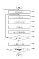
- FIG. 6 is a flowchart showing a procedure of observation processing by the optical image processing system 1 including the optical image processing module 3. As shown in FIG.
- the constructing unit 35 constructs, by machine learning, a plurality of trained models 36 that output noise-removed image data based on the training images, using the training images and the noise-removed image data as training data (step S200).
- the input unit 31 receives input of condition information indicating imaging conditions and the like from the operator (user) of the optical image processing system 1 (step S201).
- the target object F is set in the optical image processing system 1, the image of the target object F is captured, and the optical image of the target object F is acquired by the image acquiring unit 32 (step S202). Further, the selection unit 33 selects a trained model 36 from among a plurality of trained models 36 constructed in advance by machine learning, using the photodetector information included in the condition information (step S203). .
- the selection unit 33 selects a learning model constructed by setting a normal distribution model as the noise distribution model.
- a trained model 36 (hereinafter sometimes referred to as a "normal distribution model trained model 36") is selected.
- the selection unit 33 selects that the photodetector information is any of a CCD image sensor, a CMOS image sensor, a photodiode, an InGaAs sensor, a TDI-CCD image sensor, a TDI-CMOS image sensor, and a camera tube, If the information indicating the amount of light is equal to or greater than the reference value, the trained model 36 of the normal distribution model is selected. Further, when the photodetector 21 indicated by the photodetector information is not of the electron multiplying type and the amount of light is small, the selection unit 33 selects the learned model 36 ( Hereafter, it may be referred to as "the trained model 36 of the Poisson distribution model").
- the selection unit 33 selects the learned model 36 of the Poisson distribution model when the photodetector information indicates one of the above photodetectors and the information indicating the amount of light is less than a reference value.
- the selection unit 33 selects a trained model 36 (hereinafter referred to as " (sometimes referred to as "pre-trained model 36 of the Bessel function distribution model").
- the selection unit 33 selects the trained model 36 of the Bessel function distribution model when the photodetector information is an EM-CCD image sensor.
- the selection unit 33 selects the trained model 36 constructed so as to be suitable for the photodetector 21 of the non-electron-multiplying type. Further, when the photodetector 21 of the camera 2 is of the electron multiplication type, the selection unit 33 selects the trained model 36 constructed so as to be suitable for the photodetector 21 of the electron multiplication type.
- the processing unit 34 inputs the optical image of the target object F to the learned model 36 selected by the selection unit 33, and performs noise removal processing on the optical image (step S204). Further, the optical image subjected to noise removal processing by the processing unit 34 is output to the display device 4 (step S205).
- the condition information indicating the imaging conditions when imaging the target object F is used, and the trained model 36 used for noise removal is selected from the trained models 36 constructed in advance. is selected.
- the trained model 36 selected according to the imaging environment that changes with the imaging conditions of the object F is used for noise removal, so that noise removal corresponding to changes in the imaging conditions of the object F can be realized. As a result, noise in the optical image can be effectively removed.
- the input unit 31 receives input of condition information indicating imaging conditions for imaging the object F
- the selection unit 33 uses the condition information to perform the above
- a trained model 36 to be used for noise removal processing is selected
- each trained model 36 is a trained model constructed in advance by machine learning using a noise distribution model
- the selection unit 33 corresponds to the condition information. to select a pre-built trained model 36 .
- the most appropriate trained model 36 is selected from among a plurality of trained models 36 that appropriately remove noise, taking into consideration the imaging conditions of the target object F. Noise removal in the optical image of the object F becomes possible.
- the condition information is the same, the same trained model 36 can be used even if the imaging environment of the object F is different.
- CMOS image sensor Hamamatsu Photonics C14440-20 ORCA (commercial registration)-Fusion
- the object F is irradiated with visible light as observation light.
- the standard deviation of noise in optical image G1 was 6.91 and the standard deviation of noise in optical image G6 was 0.66.
- CMOS image sensor C15440-20 ORCA (commercial registration)-FusionBT manufactured by Hamamatsu Photonics Co., Ltd.) different from the above two CMOS image sensors is used, and the object F is irradiated with visible light as observation light.
- the standard deviation of noise in optical image G1 was 6.91 and the standard deviation of noise in optical image G6 was 0.65.
- an InGaAs sensor C12741-03 InGaAs camera manufactured by Hamamatsu Photonics Co., Ltd.
- the standard deviation of noise in the optical image G1 is 7. .54 and the standard deviation of noise in optical image G6 was 2.69.
- a normal distribution model is set as the noise distribution model because the photodetector 21 that is not of the electron multiplier type is used.
- An EM-CCD image sensor (C9100-23B ImagEM (registered trademark) X2 EM-CCD camera manufactured by Hamamatsu Photonics Co., Ltd.) is used as the photodetector 21, and the amplification factor is 300 times.
- F irradiated.
- the digital value was 2200 (count)
- the standard deviation of noise in the optical image G1 was 41.5
- the standard deviation of noise in the optical image G6 was 5.66.
- the digital value was 2500 (count)
- the standard deviation of noise in the optical image G1 was 44.1
- the standard deviation of noise in the optical image G6 was 7.73.
- the amplification factor is 1200 times under the above conditions. Specifically, when the digital value was 2200 (count), the standard deviation of noise in the optical image G1 was 86.9, and the standard deviation of noise in the optical image G6 was 13.2. . When the digital value was 2500 (count), the standard deviation of noise in the optical image G1 was 91.5, and the standard deviation of noise in the optical image G6 was 15.5. In each of the above examples, since the electron multiplier photodetector 21 is used, a Bessel function distribution model is set as the noise distribution model.
- the most suitable trained model 36 out of a plurality of trained models 36 according to the type of the photodetector 21 is selected, it is possible to obtain the optical image G6 from which the noise in the optical image G1 is effectively removed.
- the condition information includes photodetector information (information) indicating the type of the photodetector 21 used to image the target object F
- each trained model 36 includes the condition information
- a trained model constructed according to the type of the photodetector 21 that can be input as a noise distribution model that the selection unit 33 corresponds to the type of the photodetector 21 indicated by the photodetector information.
- a pre-built trained model 36 is selected. In general, it can be said that the characteristics of noise with respect to luminance differ depending on the type of photodetector 21 .
- the trained model 36 corresponding to the photodetector 21 used for imaging the object F is selected from among the plurality of trained models 36 constructed according to the type of the photodetector 21. Therefore, noise removal in the optical image of the object F corresponding to the photodetector 21 used for the object F is possible.
- the noise distribution model used to build the learned model 36 includes a normal distribution model.
- the learned model 36 constructed by machine learning using a normal distribution model is selected. can effectively remove noise in the optical image.
- the noise distribution model used to build the trained model 36 includes a Bessel function distribution model.
- the learned model 36 constructed by machine learning using the Bessel function distribution model is selected to optically It can effectively remove noise in the image.
- the optical image processing module 3 of the first embodiment uses structure images to which noise is added based on a predetermined noise distribution model as training images, training images, and noise-removed images that are data obtained by removing noise from the training images.
- a construction unit 35 is provided for constructing a trained model 36 that outputs noise-removed image data based on training images, using the data as training data, by machine learning. According to the above configuration, when an optical image is input to the learned model 36, noise removal processing that can effectively remove noise in the optical image of the target object F can be realized.
- the optical image processing module 3 of the first embodiment has a preprocessing function that generates a structure image to which noise is added based on the noise distribution model as a training image. Thereby, when the optical image is input to the trained model 36 generated by the preprocessing method and constructed using the training images for the machine learning method, the noise in the optical image of the object F is reduced. Noise removal processing that can effectively remove noise can be realized.
- the optical image processing module 3 of the first embodiment accepts input of condition information including photodetector information indicating the type of the photodetector 21 used for imaging the object F, and in the training image generation process, the photodetector It has the function of determining the noise distribution model to be used from the information.
- condition information including photodetector information indicating the type of the photodetector 21 used for imaging the object F
- the photodetector It has the function of determining the noise distribution model to be used from the information.
- the relationship between pixel values and noise in an optical image varies depending on the type of photodetector 21 used to image the object F. According to the above configuration, the type of photodetector 21 used to image the object F is considered, it is possible to obtain training images in which noise is appropriately added to the optical images. As a result, a trained model 36 that performs noise removal in the optical image of the object F corresponding to the photodetector 21 can be constructed.
- the noise distribution models used for generating training images include a normal distribution model and a Poisson distribution model.
- a general photodetector 21 that is not an electron multiplying type is used for imaging the object F, it is possible to obtain a training image in which noise is appropriately added to the structure image. Become.
- a trained model 36 that performs noise removal in the optical image of the object F corresponding to the photodetector 21 can be constructed.
- the noise distribution model further includes a Poisson distribution model in addition to the normal distribution model, even when the light amount of the light L is small, a training image in which noise is appropriately added to the structure image can be obtained. can be obtained.
- the noise distribution model includes a Bessel function distribution model.
- FIG. 7 is a block diagram showing the functional configuration of the optical image processing system 1A of the second embodiment.
- FIG. 8 is a diagram showing an example of input/output data of the trained model 36A of FIG.
- the optical image processing module 3A of the second embodiment differs from that of the first embodiment described above in that it has an image acquiring section (second image acquiring section) 30A and a specifying section 37A.
- each trained model 36A is a learning model constructed in advance by machine learning using image data
- the selection unit 33A Select a trained model 36A from among a plurality of trained models 36A using image characteristics (details will be described later) of a jig image (optical image of a structure), which is an optical image of a jig (structure). It differs in that it has a function to Specifically, as shown in FIG. 8, in the noise removal phase, the optical image processing module 3A first acquires a jig image G27.
- the optical image processing module 3A identifies the image characteristics of the jig image G27 based on the jig image G27, and selects the trained model 36A to be used for noise removal processing based on the identified image characteristics.
- Each trained model 36A is a machine-learned model pre-constructed using image data as teacher data.
- teacher data image data captured with various types of photodetectors 21, gain setting values, readout modes, and the like can be used.
- the image data may be an optical image actually generated for a plurality of types of objects F using the optical image processing module 3A, or may be image data generated by simulation calculation.
- FIG. 9 is a flowchart showing the procedure of observation processing by the optical image processing system 1A including the optical image processing module 3A of FIG. As shown in FIG. 9, in the optical image processing module 3A according to the second embodiment, the processes shown in steps S301 and S303 are performed by the optical image processing module 3 according to the first embodiment shown in FIG. It is executed in place of the processing of S203.
- the image acquisition unit 30A acquires a jig image by capturing an image of light from the jig (step S301). Specifically, the image acquisition unit 30A acquires an optical image obtained by capturing the light from the jig using the camera 2 .
- the light from the jig includes fluorescence from the jig, reflected light from the jig, transmitted light from the jig, scattered light from the jig, and the like.
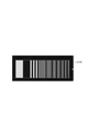
- a jig having a gray scale chart capable of evaluating the gradation performance with density steps that change step by step, or a chart of various resolutions is used.
- the image acquiring section 30A acquires the jig image G27 captured using the camera 2 prior to the observation processing of the object F.
- the image acquisition section (first image acquisition section) 32A acquires an optical image of the target object F imaged using the camera 2 .
- the acquisition timing of the optical images of the jig and the object F is not limited to the above, and may be simultaneous or opposite.
- the specifying unit 37A specifies the image characteristics of the jig image (step S302). Specifically, the specifying unit 37A specifies brightness-noise characteristics, resolution characteristics, or the like as the image characteristics of the jig image.
- the specifying unit 37A determines the noise characteristics of the optical image of the jig for each of the plurality of measurement areas. By analyzing the luminance value and noise, a luminance-noise ratio characteristic graph can be obtained as a noise characteristic.
- the brightness-to-noise ratio of an optical image can be measured using a grayscale chart. That is, the identifying unit 37A analyzes the luminance value and noise for each of a plurality of measurement regions having different densities, and obtains a luminance-noise ratio characteristic graph.
- FIG. 10 shows a jig image G27 of the jig, which is a grayscale chart.
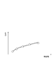
- FIG. 11 shows an example of a luminance-SNR characteristic graph acquired by the specifying unit 37A.
- the identifying unit 37A may obtain, as the noise characteristic, a characteristic graph in which noise calculated from the standard deviation of luminance values is plotted on the vertical axis instead of the luminance-SNR characteristic graph.
- the specifying unit 37A can also acquire the resolution distribution in the optical image of the jig as the resolution characteristics. Furthermore, the specifying unit 37A also has a function of obtaining resolution characteristics of an image obtained by applying a plurality of learned models 36A to the optical image of the jig and performing noise removal processing on the image.
- FIG. 12 shows a jig image G26 of the jig, which is a resolution chart.
- the resolution of the jig image can be measured using MTF (Modulation Transfer Function) or CTF (Contrast Transfer Function).
- the identifying unit 37A applies a plurality of learned models 36A to the jig image.
- the identifying unit 37A acquires, as the image characteristic, the brightness-noise ratio characteristic generated as a result of applying a plurality of trained models 36A.
- the specifying unit 37A acquires, as the image characteristic, the resolution characteristic, which is the distribution of the resolution of the noise-removed image generated as a result of applying the plurality of trained models 36A.
- the selecting unit 33A selects the learned models 36A stored in the optical image processing module 3A for use in noise removal processing.
- the completed model 36A is selected (step S303). Specifically, the selection unit 33A selects an image with relatively excellent characteristics based on the characteristics of the jig image after performing noise removal processing by applying a plurality of trained models 36A. Select the trained model 36A used to generate the . For example, when the jig is a grayscale chart, the selection unit 33A selects a learning chart constructed from image data having a brightness-to-noise ratio characteristic that is closest to the brightness-to-noise ratio characteristic acquired by the specifying unit 37A.
- the trained model 36A is selected as the final trained model 36A.
- the selection unit 33A uses the resolution characteristic specified by the specification unit 37A to select an image with the smallest change in resolution of each distribution before and after the noise removal process. Select the learned model 36A.
- the resolution chart can also be used as an aid when using the grayscale chart.
- a grayscale chart may be used to select a trained model 36 that satisfies the condition that there is no change in the resolution obtained by the resolution chart.
- the image characteristics of the image data used to build the learned model 36A may be obtained from the image data by the selection unit 33A, or may be obtained by referring to those previously calculated outside the optical image processing module 3A. good too.
- the selection unit 33A may select the learned model 36A using the luminance-noise characteristic instead of the luminance-noise ratio characteristic as the noise characteristic.
- luminance-noise characteristics By using such luminance-noise characteristics, dominant noise factors (shot noise, readout noise value, etc.) can be obtained from the slope of the graph of each signal amount region for each signal amount detected by the photodetector 21. ) can be identified and a trained model 36A can be selected based on the results of that identification.
- the optical image processing module 3A of the second embodiment described above includes an image acquisition unit 30A that acquires a jig image, and an identification unit 37A that identifies image characteristics of the jig image.
- a trained model 36A to be used for noise removal processing is selected from among a plurality of trained models 36A, and each trained model 36A is preliminarily machine-learned using image data. It is a constructed trained model, and the selection unit 33 selects a trained model 36 constructed in advance based on the image characteristics.
- the image characteristics of the optical image of the structure are specified, and based on the image characteristics, the trained model 36A to be used for noise removal is selected from the trained models 36A constructed in advance. This makes it possible to achieve optimal noise reduction for each image characteristic. [Modification]
- the constructing unit 35 may generate a training image by actually capturing images when constructing each trained model 36 . That is, the training images may be optical images actually generated using the camera 2 for a plurality of types of known structures.
- the optical image processing system 1 may be of scan type.
- the example shown in FIG. 13 differs from the above embodiments in that the optical image processing system 1 includes a confocal microscope 2B.
- the confocal microscope 2B acquires images that allow the construction of an optical tomogram of the object F.
- a confocal microscope 2B is configured by connecting a confocal microscope unit 6 to a connection port P1 of a microscope 7 for connecting an external unit.
- the confocal microscope unit 6 irradiates an object F placed on the stage of the microscope 7 or the like with excitation light via a microscope optical system such as an imaging lens 71 and an objective lens 72 in the microscope 7,
- This apparatus receives (detects) the fluorescence (light) from the object F via the microscope optical system of the microscope 7 according to the excitation light, generates and outputs an optical tomographic image.
- the confocal microscope unit 6 includes a main housing 61 , a lens barrel 62 , a scan mirror 63 fixed in the main housing 61 , a fixed mirror 64 , a subunit 65 , and a and a fixed scan lens 66 .
- the lens barrel 62 forms part of the main housing 61 and is detachably connected to the connection port P1 of the microscope 7 .
- Each component of the confocal microscope unit 6 will be described in detail below.
- a scan lens 66 in the lens barrel 62 relays the reflecting surface of the scan mirror 63 to the pupil position of the objective lens 72 and at the same time converges the excitation light (observation light) on the primary imaging plane of the microscope optical system of the microscope 7 . It is an optical element for The scan lens 66 guides the excitation light scanned by the scan mirror 63 to the microscope optical system to irradiate the object F, and in response, directs the fluorescence (observation light) generated from the object F to the scan mirror 63. guide light. Specifically, the scan lens 66 is configured to image the pupil of the objective lens 72 onto the scan mirror 63, and directs the fluorescence imaged by the objective lens 72 and the imaging lens 71 of the microscope 7 to the scan mirror 63. .
- the scan mirror 63 in the main housing 61 is, for example, an optical scanning element such as a MEMS (Micro Electro Mechanical System) mirror configured so that a reflector can be tilted on two axes.
- the scan mirror 63 continuously changes the reflection angle to scan the excitation light output from the subunit 65 onto the object F, and directs the fluorescence generated in response to the excitation light toward the subunit 65. It has a guiding role.
- the fixed mirror 64 is a light reflecting element fixed in the main housing 61, reflects the excitation light output from the subunit 65 toward the scan mirror 63, and converts the fluorescence reflected by the scan mirror 63 into the excitation light. , and is reflected toward the subunit 65 .
- the subunit 65 has a base plate 651 , a total reflection mirror 652 arranged on the base plate 651 , a light source 653 , a dichroic mirror 654 , a pinhole plate 655 and a photodetector 656 .
- Total reflection mirror 652 reflects the first excitation light of wavelength ⁇ 1 emitted by subunit 65 and the first fluorescent light of wavelength range ⁇ 1 generated from object F accordingly.
- the dichroic mirror 654 is provided in the reflection direction of the first fluorescence of the total reflection mirror 652, transmits the first fluorescence in the wavelength range ⁇ 1, and reflects the first excitation light in the wavelength ⁇ 1 shorter than the wavelength range ⁇ 1.
- the light source 653 is a light-emitting element (for example, a laser diode) that outputs first excitation light (for example, laser light) of wavelength ⁇ 1, and the first excitation light is coaxially coupled to the first fluorescence by the dichroic mirror 654. It is arranged to be reflected toward the reflecting mirror 652 .
- the pinhole plate 655 is arranged so that the pinhole position coincides with the conjugate position of the spot of the first excitation light on the object F, and is a diaphragm member that limits the light flux of the first fluorescence. constitutes a confocal optical system.
- the pinhole plate 655 can adjust the diameter of the pinhole from the outside and change the resolution of the image detected by the photodetector 656 and the signal intensity of the image.
- the photodetector 656 has its detection surface facing the pinhole plate 655 and receives and detects the first fluorescence that has passed through the pinhole plate 655 .
- Examples of the photodetector 656 include photodetectors similar to those of the above embodiments (eg, CCD image sensor, CMOS image sensor, etc.).
- the subunit 65 captures the light from the object F using the photodetector 656 and outputs a digital signal based on the captured result to the optical image processing module 3 .
- the image acquisition section 32 of the optical image processing module 3 acquires an optical image by generating image data based on the digital signal received from the subunit 65 .
- FIG. 14 shows an optical image G1 and an optical image G6 when a PMT is used as the photodetector 656 and the object F is irradiated with visible light as observation light.
- the condition information input from the input unit 31 is not limited to photodetector information.
- the condition information includes information indicating the gain setting value of the photodetector 21 used for imaging the object F, and each trained model 36 is set according to the gain setting value of the photodetector 21 that can be input as the condition information.
- the selection unit 33 may select a learned model 36 that has been previously constructed corresponding to the gain setting value of the photodetector 21 indicated by the photodetector information. In that case, the constructing unit 35 constructs a plurality of trained models 36 as follows. First, differences between the above-described embodiment and this modified example in the training image creation procedure will be mainly described.
- step S102 the construction unit 35 acquires the magnitude of noise in accordance with the gain setting value assumed to be input.
- the construction unit 35 first selects a suitable relational expression based on the photodetector information. Then, the constructing unit 35 sets the constant G (information representing the gain setting value) included in the selected relational expression for each gain setting value assumed to be input, and determines the noise for each gain setting value. Calculate the size.
- a suitable relational expression is selected from the above expressions (2) and (3) including the constant G. Then, the constructing unit 35 generates a training image for each gain setting value based on the noise distribution model set using the sigma value in the same manner as in the above embodiment (steps S103 to S107).
- step S ⁇ b>201 the input unit 31 accepts input of condition information including photodetector information and gain setting values from the operator (user) of the optical image processing system 1 .
- step S203 the selection unit 33 selects the trained model 36 from among a plurality of trained models 36 constructed in advance by machine learning using the photodetector information and the gain setting value included in the condition information. selected. That is, in this modified example, the trained model 36 of the normal distribution model, the trained model 36 of the Poisson distribution model, and the trained model 36 of the Bessel function distribution model are constructed for each gain setting value assumed to be input. An appropriate learned model 36 corresponding to the gain setting value is selected from among the plurality of learned models 36 constructed in this manner.
- the learned model 36 corresponding to the gain setting value is selected from among a plurality of learned models 36 constructed according to the gain setting value of the photodetector 21. Therefore, the gain Noise can be removed from the optical image of the object F corresponding to the set value.
- the condition information includes information indicating the readout mode of the photodetector 21 used for imaging the target object F
- each trained model 36 is configured according to the readout mode of the photodetector 21 that can be input as the condition information.
- the selection unit 33 may select a learned model 36 that has been previously constructed corresponding to the readout mode of the photodetector 21 indicated by the photodetector information.
- the constructing unit 35 constructs a plurality of trained models 36 as follows. First, differences between the above-described embodiment and this modified example in the training image creation procedure will be mainly described. In step S102, the construction unit 35 acquires the magnitude of noise according to the readout mode assumed to be input.
- the construction unit 35 first selects a suitable relational expression based on the photodetector information. Then, the construction unit 35 sets the constant R (information indicating the readout noise value corresponding to the readout mode) included in the selected relational expression for each readout noise value assumed to be input, and Calculate the magnitude of the noise for each value.
- a suitable relational expression is selected from the above expressions (1) and (2) including the constant R. Then, the constructing unit 35 generates a training image for each readout noise value based on the noise distribution model set using the sigma value in the same manner as in the above embodiment (steps S103 to S107).
- step S ⁇ b>201 the input unit 31 receives input of condition information including photodetector information and readout noise value information from the operator (user) of the optical image processing system 1 .
- step S203 the selection unit 33 selects the trained model 36 from among a plurality of trained models 36 constructed in advance by machine learning using the photodetector information and the readout noise value included in the condition information. selected. That is, in this modification, a trained model 36 of the normal distribution model, a trained model 36 of the Poisson distribution model, and a trained model 36 of the Bessel function distribution model are constructed for each readout noise value assumed to be input. An appropriate trained model 36 corresponding to the readout noise value is selected from among the plurality of trained models 36 constructed in this manner.
- the characteristics of noise with respect to luminance differ depending on the readout mode of the photodetector 21 .
- this modification from among a plurality of learned models 36 built according to the readout mode of the photodetector 21 (specifically, the readout noise value corresponding to the readout mode), Since the trained model 36 is selected, it is possible to remove noise in the optical image of the object F corresponding to the readout mode.
- the optical image processing method further includes an input step of receiving input of condition information indicating imaging conditions when imaging the object, the imaging information includes the condition information, and each of the plurality of trained models has a predetermined noise. It is a learned model constructed in advance by machine learning using a distribution model, and in the selection step, a trained model constructed in advance corresponding to the condition information may be selected.
- the optical image processing module further includes an input unit that receives input of condition information indicating imaging conditions when imaging the object, the imaging information includes condition information, and each of the plurality of trained models has a predetermined and the selection unit may select a learned model that is pre-constructed corresponding to the condition information.
- the most suitable trained model is selected from among a plurality of trained models that appropriately remove noise, taking into consideration the imaging conditions of the object. It is possible to remove noise in the image.
- the condition information includes information indicating the type of photodetector used for imaging the object, and each of the plurality of trained models can be input as the condition information according to the type of photodetector. It is a constructed learned model, and in the selection step, a trained model constructed in advance using a predetermined noise distribution model corresponding to the type of photodetector indicated by the condition information may be selected. Further, in the optical image processing module, the condition information includes information indicating the type of photodetector used for imaging the target object, and each of the plurality of trained models corresponds to the type of photodetector that can be input as the condition information.
- the selection unit may select a trained model constructed in advance using a predetermined noise distribution model corresponding to the type of photodetector indicated by the condition information.
- a trained model corresponding to the photodetector used for imaging the object is selected from among a plurality of trained models built according to the type of the photodetector. Noise removal in the optical image of the object corresponding to the photodetector used is enabled.
- the condition information includes information indicating the gain setting value of the photodetector used for imaging the object, and each of the plurality of trained models has the gain setting of the photodetector that can be input as the condition information. It is a learned model constructed according to the value, and in the selection step, a trained model constructed in advance corresponding to the gain setting value of the photodetector indicated by the condition information may be selected. Further, in the optical image processing module, the condition information includes information indicating the gain setting value of the photodetector used for imaging the object, and each of the plurality of trained models is the photodetector that can be input as the condition information.
- the selection unit may select a learned model built in advance corresponding to the gain setting value of the photodetector indicated by the condition information.
- a learned model corresponding to the gain setting value is selected from among a plurality of trained models constructed according to the gain setting value of the photodetector. It is possible to remove noise in the optical image of the object.
- the condition information includes information indicating the readout mode of the photodetector used for imaging the object, and each of the plurality of trained models is set to the readout mode of the photodetector that can be input as the condition information.
- the selection step may select a learned model that has been previously constructed corresponding to the readout mode of the photodetector indicated by the condition information.
- the condition information includes information indicating the readout mode of the photodetector used for imaging the object, and each of the plurality of trained models is a readout mode of the photodetector that can be input as the condition information.
- the selection unit may select a trained model constructed in advance corresponding to the readout mode of the photodetector indicated by the condition information.
- a trained model corresponding to the readout mode is selected from among a plurality of trained models constructed according to the readout mode of the photodetector. can be used to remove noise in optical images.
- the noise distribution model may include at least one of a normal distribution model and a Poisson distribution model.
- a normal distribution model for example, when a general photodetector that is not an electron multiplying type is used to image an object, a trained model constructed by machine learning using a normal distribution model or a Poisson distribution model Noise in the optical image can be effectively removed by selecting a trained model constructed by machine learning.
- the noise distribution model may include a Bessel function distribution model.
- a Bessel function distribution model For example, when an electron-multiplying photodetector is used to image an object, noise in an optical image is reduced by selecting a learned model constructed by machine learning using a Bessel function distribution model. can be effectively removed.
- the optical image processing method includes a second image acquisition step of acquiring an optical image of the structure by capturing light from the structure having a predetermined structure, and a specification step of specifying image characteristics of the optical image of the structure.
- the imaging information includes image characteristics
- each of the plurality of trained models is a trained model constructed in advance by machine learning using image data
- the selection step is based on the image characteristics You may select a pre-trained model built in .
- the optical image processing module includes a second image acquisition unit that acquires an optical image of the structure by capturing an image of light from the structure having a predetermined structure, and an image characteristic of the optical image of the structure.
- the imaging information includes image characteristics
- each of the plurality of trained models is a trained model constructed in advance by machine learning using image data
- the selection unit includes image characteristics
- the machine learning preprocessing method further comprises an input step of receiving input of condition information including photodetector information indicating the type of photodetector used to image the object, and in the training image generation step, from the photodetector information , determines the noise distribution model to use.
- condition information including photodetector information indicating the type of photodetector used to image the object
- training image generation step from the photodetector information , determines the noise distribution model to use.
- the relationship between pixel values and noise in an optical image varies depending on the type of photodetector used to capture the image of the object. , it is possible to obtain training images in which noise is appropriately added to the optical images. As a result, a trained model can be built that performs denoising in the optical image of the object corresponding to the photodetector.
- the noise distribution model may include at least one of a normal distribution model and a Poisson distribution model.
- the noise distribution model may include a Bessel function distribution model.
- a Bessel function distribution model For example, when an electron-multiplying photodetector is used to image an object, it is possible to obtain a training image in which noise is appropriately added to the optical image. As a result, it is possible to build a trained model that performs denoising in the optical image of the object corresponding to the photodetector type.
Landscapes
- Physics & Mathematics (AREA)
- General Physics & Mathematics (AREA)
- Engineering & Computer Science (AREA)
- Theoretical Computer Science (AREA)
- Image Processing (AREA)
Priority Applications (4)
| Application Number | Priority Date | Filing Date | Title |
|---|---|---|---|
| JP2023531427A JP7784429B2 (ja) | 2021-06-29 | 2022-03-18 | 光学画像処理方法、機械学習方法、学習済みモデル、機械学習の前処理方法、光学画像処理モジュール、光学画像処理プログラム、及び光学画像処理システム |
| EP22832490.1A EP4343681A4 (en) | 2021-06-29 | 2022-03-18 | OPTICAL IMAGE PROCESSING METHOD, MACHINE LEARNING METHOD, LEARNED MODEL, MACHINE LEARNING PREPROCESSING METHOD, OPTICAL IMAGE PROCESSING MODULE, OPTICAL IMAGE PROCESSING PROGRAM, AND OPTICAL IMAGE PROCESSING SYSTEM |
| CN202280045897.2A CN117651967A (zh) | 2021-06-29 | 2022-03-18 | 一种光学图像处理方法、机器学习方法、训练后的模型、机器学习的预处理方法、光学图像处理模块、光学图像处理程序和光学图像处理系统 |
| US18/569,288 US12579621B2 (en) | 2021-06-29 | 2022-03-18 | Optical image processing method, machine learning method, trained model, machine learning pre-processing method, optical image processing module, optical image processing program, and optical image processing system |
Applications Claiming Priority (2)
| Application Number | Priority Date | Filing Date | Title |
|---|---|---|---|
| JP2021-107918 | 2021-06-29 | ||
| JP2021107918 | 2021-06-29 |
Publications (1)
| Publication Number | Publication Date |
|---|---|
| WO2023276327A1 true WO2023276327A1 (ja) | 2023-01-05 |
Family
ID=84692610
Family Applications (1)
| Application Number | Title | Priority Date | Filing Date |
|---|---|---|---|
| PCT/JP2022/012688 Ceased WO2023276327A1 (ja) | 2021-06-29 | 2022-03-18 | 光学画像処理方法、機械学習方法、学習済みモデル、機械学習の前処理方法、光学画像処理モジュール、光学画像処理プログラム、及び光学画像処理システム |
Country Status (5)
| Country | Link |
|---|---|
| US (1) | US12579621B2 (https=) |
| EP (1) | EP4343681A4 (https=) |
| JP (1) | JP7784429B2 (https=) |
| CN (1) | CN117651967A (https=) |
| WO (1) | WO2023276327A1 (https=) |
Families Citing this family (1)
| Publication number | Priority date | Publication date | Assignee | Title |
|---|---|---|---|---|
| JP7538174B2 (ja) * | 2022-05-23 | 2024-08-21 | 日本電子株式会社 | マスイメージ処理装置及び方法 |
Citations (3)
| Publication number | Priority date | Publication date | Assignee | Title |
|---|---|---|---|---|
| JP2020021314A (ja) | 2018-08-01 | 2020-02-06 | 浜松ホトニクス株式会社 | 画像処理装置及び画像処理方法 |
| JP2020144488A (ja) * | 2019-03-05 | 2020-09-10 | キヤノン株式会社 | 画像処理方法、画像処理装置、プログラム、画像処理システム、および、学習済みモデルの製造方法 |
| WO2021095256A1 (ja) * | 2019-11-15 | 2021-05-20 | オリンパス株式会社 | 画像処理システム、画像処理方法、及び、プログラム |
Family Cites Families (29)
| Publication number | Priority date | Publication date | Assignee | Title |
|---|---|---|---|---|
| EP1263208B1 (en) * | 2001-05-29 | 2014-09-03 | STMicroelectronics Limited | Method for generating unique image sensor indentification, and image sensor system for use therewith |
| US8442125B2 (en) * | 2005-11-29 | 2013-05-14 | Google Inc. | Determining popularity ratings using social and interactive applications for mass media |
| US8996810B2 (en) * | 2012-12-10 | 2015-03-31 | Facebook, Inc. | System and method of detecting cache inconsistencies |
| US9596390B2 (en) * | 2013-04-23 | 2017-03-14 | Olympus Corporation | Imaging apparatus, imaging method, and computer-readable recording medium |
| JP6214341B2 (ja) * | 2013-10-30 | 2017-10-18 | オリンパス株式会社 | 走査型レーザ顕微鏡装置 |
| JP6270465B2 (ja) * | 2013-12-25 | 2018-01-31 | オリンパス株式会社 | 光走査型観察装置 |
| JP6397191B2 (ja) * | 2014-01-24 | 2018-09-26 | オリンパス株式会社 | 光走査型観察装置 |
| JP6445809B2 (ja) * | 2014-09-01 | 2018-12-26 | オリンパス株式会社 | 光走査型観察装置 |
| US9967619B2 (en) * | 2014-12-01 | 2018-05-08 | Google Llc | System and method for associating search queries with remote content display |
| WO2016088772A1 (ja) * | 2014-12-02 | 2016-06-09 | オリンパス株式会社 | 可撓管及び挿入機器 |
| LU92688B1 (en) * | 2015-04-01 | 2016-10-03 | Iee Int Electronics & Eng Sa | Method and system for real-time motion artifact handling and noise removal for tof sensor images |
| US9699504B2 (en) * | 2015-09-28 | 2017-07-04 | Rovi Guides, Inc. | Systems and methods for identifying a source of media content based on a log of content identifiers |
| JP2017173653A (ja) * | 2016-03-25 | 2017-09-28 | オリンパス株式会社 | 画像取得システム |
| WO2017199285A1 (ja) * | 2016-05-16 | 2017-11-23 | オリンパス株式会社 | 画像処理装置及び画像処理方法 |
| WO2018087852A1 (ja) * | 2016-11-09 | 2018-05-17 | オリンパス株式会社 | 光走査型内視鏡装置 |
| JP6717759B2 (ja) * | 2017-01-11 | 2020-07-01 | オリンパス株式会社 | 計測装置および計測装置の作動方法 |
| JP7042025B2 (ja) * | 2017-01-23 | 2022-03-25 | ソニーセミコンダクタソリューションズ株式会社 | 情報処理装置、情報処理方法、及び記録媒体 |
| JP7027403B2 (ja) * | 2017-02-28 | 2022-03-01 | ソニーセミコンダクタソリューションズ株式会社 | 測距装置、および測距方法 |
| JP2019028718A (ja) * | 2017-07-31 | 2019-02-21 | オリンパス株式会社 | 画像解析システム |
| WO2019087253A1 (ja) * | 2017-10-30 | 2019-05-09 | オリンパス株式会社 | ステレオカメラのキャリブレーション方法 |
| WO2019102581A1 (ja) * | 2017-11-24 | 2019-05-31 | オリンパス株式会社 | 光走査型観察装置および光走査型観察装置の作動方法 |
| JP6987243B2 (ja) * | 2018-06-22 | 2021-12-22 | オリンパス株式会社 | ランドマーク推定方法、内視鏡装置、及び、位置推定プログラム |
| US10958453B2 (en) * | 2018-07-03 | 2021-03-23 | Taiwan Semiconductor Manufacturing Co., Ltd. | Method and apparatus for noise injection for PUF generator characterization |
| US11227370B2 (en) * | 2019-09-30 | 2022-01-18 | Brother Kogyo Kabushiki Kaisha | Method for generating image processing filter and image processing method using the image processing filter |
| MX2022003944A (es) * | 2019-10-02 | 2022-07-21 | Endpoint Health Inc | Paneles de biomarcadores para guiar terapia para respuesta del anfitrión desregulada. |
| US11120585B2 (en) * | 2019-11-28 | 2021-09-14 | Shanghai United Imaging Intelligence Co., Ltd. | Systems and methods for image reconstruction |
| EP4439446A3 (en) * | 2019-11-29 | 2024-12-04 | Samsung Electronics Co., Ltd | Electronic apparatus and control method thereof |
| US12367546B2 (en) * | 2019-12-24 | 2025-07-22 | Nvidia Corporation | Panorama generation using one or more neural networks |
| KR20220160359A (ko) * | 2021-05-27 | 2022-12-06 | 에스케이하이닉스 주식회사 | 이미지 장치 |
-
2022
- 2022-03-18 JP JP2023531427A patent/JP7784429B2/ja active Active
- 2022-03-18 CN CN202280045897.2A patent/CN117651967A/zh active Pending
- 2022-03-18 WO PCT/JP2022/012688 patent/WO2023276327A1/ja not_active Ceased
- 2022-03-18 US US18/569,288 patent/US12579621B2/en active Active
- 2022-03-18 EP EP22832490.1A patent/EP4343681A4/en active Pending
Patent Citations (3)
| Publication number | Priority date | Publication date | Assignee | Title |
|---|---|---|---|---|
| JP2020021314A (ja) | 2018-08-01 | 2020-02-06 | 浜松ホトニクス株式会社 | 画像処理装置及び画像処理方法 |
| JP2020144488A (ja) * | 2019-03-05 | 2020-09-10 | キヤノン株式会社 | 画像処理方法、画像処理装置、プログラム、画像処理システム、および、学習済みモデルの製造方法 |
| WO2021095256A1 (ja) * | 2019-11-15 | 2021-05-20 | オリンパス株式会社 | 画像処理システム、画像処理方法、及び、プログラム |
Non-Patent Citations (1)
| Title |
|---|
| See also references of EP4343681A4 |
Also Published As
| Publication number | Publication date |
|---|---|
| CN117651967A (zh) | 2024-03-05 |
| JPWO2023276327A1 (https=) | 2023-01-05 |
| US12579621B2 (en) | 2026-03-17 |
| EP4343681A4 (en) | 2025-05-21 |
| JP7784429B2 (ja) | 2025-12-11 |
| EP4343681A1 (en) | 2024-03-27 |
| US20240265508A1 (en) | 2024-08-08 |
Similar Documents
| Publication | Publication Date | Title |
|---|---|---|
| US12335455B2 (en) | User interface for intraoral scanning with tooth color detection | |
| US10652444B2 (en) | Multiplexed Fourier ptychography imaging systems and methods | |
| JP4826586B2 (ja) | スペクトル画像処理方法、コンピュータ実行可能なスペクトル画像処理プログラム、スペクトルイメージングシステム | |
| JP4872914B2 (ja) | スペクトル画像処理方法、スペクトル画像処理プログラム、及びスペクトルイメージングシステム | |
| US11449964B2 (en) | Image reconstruction method, device and microscopic imaging device | |
| CA2969432A1 (en) | Multiplexed fourier ptychography imaging systems and methods | |
| US10718715B2 (en) | Microscopy system, microscopy method, and computer-readable storage medium | |
| US10416427B2 (en) | Scan-based imaging with variable scan speed using predictions of region-of-interest positions | |
| JP2023539435A (ja) | 蛍光顕微鏡における照明調整方法および対応する蛍光顕微鏡 | |
| JP7784429B2 (ja) | 光学画像処理方法、機械学習方法、学習済みモデル、機械学習の前処理方法、光学画像処理モジュール、光学画像処理プログラム、及び光学画像処理システム | |
| EP4332878A1 (en) | Optical image processing method, machine learning method, trained model, machine learning preprocessing method, optical image processing module, optical image processing program, and optical image processing system | |
| CN117590575A (zh) | 用于显微术的方法和设备 | |
| WO2017217325A1 (ja) | データ復元装置、顕微鏡システム、およびデータ復元方法 | |
| JP2004537902A (ja) | 雑音を含む画像の自動閾値処理 | |
| JP4743773B2 (ja) | エッジ検出方法、装置、及びプログラム | |
| JP4968337B2 (ja) | 共焦点顕微鏡装置 | |
| KR20160014340A (ko) | 형광수명 분석 시스템 및 그 분석 방법 | |
| JP2005291720A (ja) | 蛍光検出装置、濃淡情報補正方法および濃淡情報補正プログラム | |
| JP2007158577A (ja) | 撮像データ補正方法、および、撮像データ補正装置 | |
| JP2009015318A (ja) | レーザ走査顕微鏡 |
Legal Events
| Date | Code | Title | Description |
|---|---|---|---|
| 121 | Ep: the epo has been informed by wipo that ep was designated in this application |
Ref document number: 22832490 Country of ref document: EP Kind code of ref document: A1 |
|
| WWE | Wipo information: entry into national phase |
Ref document number: 2023531427 Country of ref document: JP |
|
| WWE | Wipo information: entry into national phase |
Ref document number: 2022832490 Country of ref document: EP |
|
| WWE | Wipo information: entry into national phase |
Ref document number: 202280045897.2 Country of ref document: CN |
|
| ENP | Entry into the national phase |
Ref document number: 2022832490 Country of ref document: EP Effective date: 20231219 |
|
| NENP | Non-entry into the national phase |
Ref country code: DE |
|
| WWG | Wipo information: grant in national office |
Ref document number: 18569288 Country of ref document: US |