WO2023276124A1 - カーポート - Google Patents
カーポート Download PDFInfo
- Publication number
- WO2023276124A1 WO2023276124A1 PCT/JP2021/025013 JP2021025013W WO2023276124A1 WO 2023276124 A1 WO2023276124 A1 WO 2023276124A1 JP 2021025013 W JP2021025013 W JP 2021025013W WO 2023276124 A1 WO2023276124 A1 WO 2023276124A1
- Authority
- WO
- WIPO (PCT)
- Prior art keywords
- solar cell
- cell module
- fitting member
- carport
- inclination
- Prior art date
- Legal status (The legal status is an assumption and is not a legal conclusion. Google has not performed a legal analysis and makes no representation as to the accuracy of the status listed.)
- Ceased
Links
Images




Classifications
-
- E—FIXED CONSTRUCTIONS
- E04—BUILDING
- E04H—BUILDINGS OR LIKE STRUCTURES FOR PARTICULAR PURPOSES; SWIMMING OR SPLASH BATHS OR POOLS; MASTS; FENCING; TENTS OR CANOPIES, IN GENERAL
- E04H6/00—Buildings for parking cars, rolling-stock, aircraft, vessels or like vehicles, e.g. garages
- E04H6/02—Small garages, e.g. for one or two cars
-
- F—MECHANICAL ENGINEERING; LIGHTING; HEATING; WEAPONS; BLASTING
- F24—HEATING; RANGES; VENTILATING
- F24S—SOLAR HEAT COLLECTORS; SOLAR HEAT SYSTEMS
- F24S20/00—Solar heat collectors specially adapted for particular uses or environments
- F24S20/60—Solar heat collectors integrated in fixed constructions, e.g. in buildings
- F24S20/67—Solar heat collectors integrated in fixed constructions, e.g. in buildings in the form of roof constructions
-
- H—ELECTRICITY
- H02—GENERATION; CONVERSION OR DISTRIBUTION OF ELECTRIC POWER
- H02S—GENERATION OF ELECTRIC POWER BY CONVERSION OF INFRARED RADIATION, VISIBLE LIGHT OR ULTRAVIOLET LIGHT, e.g. USING PHOTOVOLTAIC [PV] MODULES
- H02S20/00—Supporting structures for PV modules
- H02S20/10—Supporting structures directly fixed to the ground
-
- H—ELECTRICITY
- H02—GENERATION; CONVERSION OR DISTRIBUTION OF ELECTRIC POWER
- H02S—GENERATION OF ELECTRIC POWER BY CONVERSION OF INFRARED RADIATION, VISIBLE LIGHT OR ULTRAVIOLET LIGHT, e.g. USING PHOTOVOLTAIC [PV] MODULES
- H02S20/00—Supporting structures for PV modules
- H02S20/20—Supporting structures directly fixed to an immovable object
-
- H—ELECTRICITY
- H02—GENERATION; CONVERSION OR DISTRIBUTION OF ELECTRIC POWER
- H02S—GENERATION OF ELECTRIC POWER BY CONVERSION OF INFRARED RADIATION, VISIBLE LIGHT OR ULTRAVIOLET LIGHT, e.g. USING PHOTOVOLTAIC [PV] MODULES
- H02S20/00—Supporting structures for PV modules
- H02S20/20—Supporting structures directly fixed to an immovable object
- H02S20/22—Supporting structures directly fixed to an immovable object specially adapted for buildings
- H02S20/23—Supporting structures directly fixed to an immovable object specially adapted for buildings specially adapted for roof structures
-
- H—ELECTRICITY
- H02—GENERATION; CONVERSION OR DISTRIBUTION OF ELECTRIC POWER
- H02S—GENERATION OF ELECTRIC POWER BY CONVERSION OF INFRARED RADIATION, VISIBLE LIGHT OR ULTRAVIOLET LIGHT, e.g. USING PHOTOVOLTAIC [PV] MODULES
- H02S20/00—Supporting structures for PV modules
- H02S20/20—Supporting structures directly fixed to an immovable object
- H02S20/22—Supporting structures directly fixed to an immovable object specially adapted for buildings
- H02S20/23—Supporting structures directly fixed to an immovable object specially adapted for buildings specially adapted for roof structures
- H02S20/24—Supporting structures directly fixed to an immovable object specially adapted for buildings specially adapted for roof structures specially adapted for flat roofs
-
- H—ELECTRICITY
- H02—GENERATION; CONVERSION OR DISTRIBUTION OF ELECTRIC POWER
- H02S—GENERATION OF ELECTRIC POWER BY CONVERSION OF INFRARED RADIATION, VISIBLE LIGHT OR ULTRAVIOLET LIGHT, e.g. USING PHOTOVOLTAIC [PV] MODULES
- H02S20/00—Supporting structures for PV modules
- H02S20/20—Supporting structures directly fixed to an immovable object
- H02S20/22—Supporting structures directly fixed to an immovable object specially adapted for buildings
- H02S20/23—Supporting structures directly fixed to an immovable object specially adapted for buildings specially adapted for roof structures
- H02S20/25—Roof tile elements
-
- Y—GENERAL TAGGING OF NEW TECHNOLOGICAL DEVELOPMENTS; GENERAL TAGGING OF CROSS-SECTIONAL TECHNOLOGIES SPANNING OVER SEVERAL SECTIONS OF THE IPC; TECHNICAL SUBJECTS COVERED BY FORMER USPC CROSS-REFERENCE ART COLLECTIONS [XRACs] AND DIGESTS
- Y02—TECHNOLOGIES OR APPLICATIONS FOR MITIGATION OR ADAPTATION AGAINST CLIMATE CHANGE
- Y02B—CLIMATE CHANGE MITIGATION TECHNOLOGIES RELATED TO BUILDINGS, e.g. HOUSING, HOUSE APPLIANCES OR RELATED END-USER APPLICATIONS
- Y02B10/00—Integration of renewable energy sources in buildings
- Y02B10/10—Photovoltaic [PV]
-
- Y—GENERAL TAGGING OF NEW TECHNOLOGICAL DEVELOPMENTS; GENERAL TAGGING OF CROSS-SECTIONAL TECHNOLOGIES SPANNING OVER SEVERAL SECTIONS OF THE IPC; TECHNICAL SUBJECTS COVERED BY FORMER USPC CROSS-REFERENCE ART COLLECTIONS [XRACs] AND DIGESTS
- Y02—TECHNOLOGIES OR APPLICATIONS FOR MITIGATION OR ADAPTATION AGAINST CLIMATE CHANGE
- Y02E—REDUCTION OF GREENHOUSE GAS [GHG] EMISSIONS, RELATED TO ENERGY GENERATION, TRANSMISSION OR DISTRIBUTION
- Y02E10/00—Energy generation through renewable energy sources
- Y02E10/50—Photovoltaic [PV] energy
Definitions
- the present invention relates to carports.
- Patent Documents 1 and 2 In a photovoltaic power generation system using solar cell modules, it is necessary to obtain sufficient sunlight in order to increase the amount of power generation. For this reason, solar cell modules have been installed on the roofs of houses, buildings, etc., which receive a lot of sunlight. , Patent Documents 1 and 2).
- the vertical rails are supported by a pair of supports so as to be inclined downward from the front to the rear of the parking lot, and the holding members, which are a plurality of horizontal rails, are supported by a plurality of solar cells.
- Each of the battery modules is held without any gaps in the vertical direction and with gaps along the horizontal rails in the horizontal direction.
- solar cell modules have manufacturing tolerances, and it is difficult to install them without gaps. Therefore, rainwater or the like may leak through the gaps between the solar cell modules.
- the joint member which is T-shaped in a cross-sectional view, is inserted into the gap from above the solar cell module so that the flange portion comes into contact with the upper surface of the solar cell module. prepare. Since the joint member is inserted into the gap between the solar cell modules in this way, it is possible to suppress rain leakage from the gap.
- Patent Document 2 the web is inserted from above the solar cell module into the gap so that the flange portion contacts the upper surface of the solar cell module, so there is a problem of low workability.
- the present invention has been made in view of the above problems, and an object of the present invention is to provide a carport that can suppress leakage of rainwater and the like from gaps between adjacent solar cell modules and that is highly workable.
- a carport according to the present invention includes a roof member in which a plurality of solar cell modules are arranged in a first direction and in a second direction intersecting the first direction.
- the battery modules are a carport installed so as to be continuously inclined as a whole, and a water flow along the second direction is formed in the gaps between the solar battery modules that are adjacent to each other in the first direction.
- the fitting member is fitted with the solar cell module located on the lower side of the inclination in the first direction while being spaced apart from the solar cell module located on the upper side of the inclination in the first direction.
- a connecting portion installed so as to abut on at least a part of an inclined upper side surface of a battery module; and an inclined lower side of the lower surface of the solar cell module extending from the connecting portion and located on the inclined upper side in the first direction. and a lower flange portion that abuts on the end portion.
- the fitting member is spaced apart from the solar cell module on the upper side of the inclination in the first direction and is attached to at least a part of the side surface of the upper side of the solar cell module on the lower side of the inclination in the first direction. and a lower flange portion extending from the connecting portion and abutting on the inclined lower end portion of the lower surface of the solar cell module located on the inclined upper side in the first direction.
- the fitting member has an upper flange portion extending from the connection portion and abutting from above on an upper inclined end portion of the upper surface of the solar cell module located on the lower inclined side in the first direction. is preferred. By having the upper flange portion, it is possible to further suppress water leakage from between the solar cell module on the lower side of the inclination and the fitting member.
- a plurality of first crosspieces are provided along the first direction, and the solar cell modules are mounted on each side facing the adjacent first crosspieces. It is preferable that an engaging portion that engages with one crosspiece is formed, the engaging portion engages with the first crosspiece, and the fitting member is fixed to the first crosspiece.
- the fitting member is formed with an engaging portion that engages with the first crosspiece, and the engaging portion engages with the first crosspiece to fix the fitting member to the first crosspiece. , the fitting member can be easily fixed at a desired position.
- the engaging portion is a notch portion that fits into a convex portion formed on the first crosspiece. Since the fitting member has such a notch portion, it is possible to easily engage the fitting member with the first crosspiece and to maintain the distance between the first crosspieces.
- a concave portion defined by the convex portion may be formed on the upper surface of the first crosspiece along its longitudinal direction, and an outer end portion of the notch portion of the fitting member may be inserted into the concave portion.
- the notch portion of the fitting member is fitted to the projection formed on the first crosspiece, the outer end of the notch portion of the fitting member is inserted into the recess, so that the fitting member The water in the formed groove more reliably flows into the recess of the first crosspiece, and water leakage can be prevented more reliably.
- the connecting portion is installed in contact with the entire surface of the side surface on the upper side of the inclination of the solar cell module located on the lower side of the inclination in the first direction.
- the lower flange portion has a raised portion that rises upward at its tip.
- the volume of the groove formed between the fitting member and the solar cell module located on the inclined upper side is increased, so that it becomes easier to flow water in the second direction. , can prevent water leakage.
- the fitting member has an extension part extending from the connection part toward the solar cell module located on the upper side of the inclination in the first direction.
- the extension portion extends upward from the connection portion toward the solar cell module located on the upper side of the inclination in the first direction.
- the fitting member includes a contact member that contacts a side surface of the solar cell module on the lower side of the inclination in the first direction.
- the fitting member has the abutment members at both ends in the longitudinal direction of the extension portion.
- the abutment members are in contact only with both ends of the side surface of the solar cell module, even if there is a manufacturing tolerance in the central portion of the side surface of the solar cell module, the abutment members do not interfere with each other, and water does not enter the groove. It is difficult to block the flow.
- the contact member is preferably a seal member fixed to the connecting portion.
- the extending portion is provided so as to cover at least a portion of the sealing member in plan view. It is possible to prevent deterioration of the sealing member.
- the carport of the present invention it is possible to suppress the leakage of rainwater and the like from gaps between adjacent solar cell modules, and the workability is high.
- FIG. 1 is a perspective view of an upper rail according to a first embodiment of the present invention
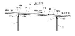
- FIG. BRIEF DESCRIPTION OF THE DRAWINGS It is a partial side schematic diagram of the carport concerning 1st embodiment of this invention.
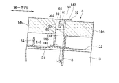
- BRIEF DESCRIPTION OF THE DRAWINGS It is a partial top view of the carport concerning 1st embodiment of this invention. It is a partial cross-sectional view of the carport according to the first embodiment of the present invention. It is a perspective view showing a fitting member concerning a first embodiment of the present invention.
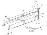
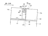
- FIG. 4 is a front view showing the relationship between the fitting member and the upper rail according to the first embodiment of the present invention; It is a partial cross-sectional view at the end of the fitting member in the carport according to the second embodiment of the present invention. It is a perspective view which shows the fitting member concerning 2nd embodiment of this invention. It is a partial sectional view in the central part of the fitting member in the carport concerning a second embodiment of the present invention.
- the pillars 11 are installed in two rows along the first direction shown in FIG. 1 and in three rows along the second direction perpendicular to the first direction. It is erected so as to be perpendicular to the Two lower crosspieces 12a and 12b are respectively fixed over three support columns 11 erected along the second direction. That is, in the carport 1, as shown in FIG. 3, two lower rails 12a and 12b are fixed to three columns 11 through connectors 111a and 111b so as to be parallel to each other in the second direction. ing. At this time, since the connector 111a of the lower rail 12a is adjusted to be higher than the connector 111b of the lower rail 12b by the desired height, the lower rail 12a is fixed at a position higher than the lower rail 12b. It is
- eleven upper rails 13 parallel to each other along the first direction are mounted on the lower rails 12a and 12b, and connecting members 121a and 121b are connected. It is fixed to the upper part of the lower rail 12a and the lower rail 12b by 121b (see FIG. 3).
- the eleven upper crosspieces 13 are spaced apart from each other at predetermined intervals. Since the lower rails 12a and 12b extend along the second direction and the upper rail 13 extends along the first direction, the upper rail 13 and the lower rail 12 form a right angle when viewed from above.
- the upper rail 13 is provided with a pair of side walls 131 along its longitudinal direction, and plate-shaped portions 132 are provided on the upper portions of the side walls 131, respectively.
- the plate-like portion 132 is formed such that its upper surface is parallel to the bottom surface of the upper rail 13 .
- a concave portion 133 defined inside the upper rail 13 by the side wall 131 faces a gap 134 between the pair of plate-like portions 132 .
- the recesses 133 are open at both ends of the upper rail 13 .
- the upper rail 13 is laid over the lower rails 12a and 12b with the gap 134 facing upward.
- the connector 111a of the lower rail 12a is installed so as to be higher than the connector 111b of the lower rail 12b by a desired height
- the upper rails 12a and 12b are installed.
- the crosspiece 13 is also fixed to the lower crosspieces 12a and 12b with an inclination so that the lower crosspiece 12a side is higher and the lower crosspiece 12b side is relatively lower. That is, the upper rail 13 is fixed so as to be inclined in the first direction.
- the inclination from the side of the lower rail 12a to the side of the lower rail 12b is defined as the direction of inclination in this embodiment, with the higher side being the upper side of the slope and the lower side being the lower side of the slope.
- the lower rails 12a and 12b are one rod-shaped member that is long in the second direction for the sake of explanation.
- the upper rail 13 is also the same.
- a solar cell module 14 having a rectangular shape when viewed from above is fixed onto the upper rail 13 .
- the solar cell modules 14 are arranged side by side in the first direction and the second direction so as to form three rows in the first direction and ten rows in the second direction. .
- each long side of each solar cell module 14 is placed on the upper beams 13 and spanned between adjacent upper beams 13 .
- each solar cell module 14 is provided so that the upper beam 13 is inclined in the first direction
- the solar cell module 14 is also installed so as to be continuously inclined in the first direction as shown in FIG. It is In FIG. 3, the same solar cell modules are referred to as solar cell modules 14a, 14b, and 14c from the inclined upper side. That is, in the carport 1, the solar cell modules are installed so that the left end of the solar cell module 14a in FIG. 3 is the highest and the right end of the solar cell module 14c in FIG. 3 is the lowest.
- the water flows along the inclination direction, that is, from the solar cell module 14a on the upper side of the inclination toward the solar cell module 14c on the lower side of the inclination.
- Rainwater is configured to flow over the surface of each solar cell module 14 .
- the solar cell modules 14 are fixed on the upper rail 13 with gaps between adjacent solar cell modules 14 .
- a gap 134 facing a concave portion 133 provided on the upper surface of the upper rail 13 faces from the gap in the second direction.
- This recess 133 functions as a rain gutter.
- a fitting member 20 is installed in the gap between the solar cell modules 14 in the first direction, that is, between the short sides of the solar cell modules 14b and 14c.
- the fitting member 20 spans between the upper beams 13 adjacent to each other.
- a groove portion 30 is formed by the fitting member 20 and the solar cell module 14b on the inclined upper side, and the groove portion 30 guides rainwater to flow in the second direction. Then, this rainwater flows into the recessed portion 133 of the upper beam 13, passes through the recessed portion 133 functioning as a rain gutter, and is discharged from the lower end of the solar cell module 14 at the lowest position.
- the fitting member 20 abuts on the lower flange portion 21 that abuts on the lower end portion 141 of the bottom surface of the solar cell module 14b on the inclined upper side, and the upper end portion 142 on the upper surface of the solar cell module 14c on the inclined lower side.
- An upper flange portion 22 and a connection portion 23 connecting the lower flange portion 21 and the upper flange portion 22 are provided.
- the lower flange portion 21 and the upper flange portion 22 extend in opposite directions to the connection portion 23 .
- the connecting portion 23 of the fitting member 20 is directly connected to the upper flange portion 22 and has an upper wall surface portion 24 that abuts on the upper side surface 144 of the solar cell module 14c on the inclined lower side. Further, the connection portion 23 includes a stepped portion 25 extending from the upper wall portion 24 toward the solar cell module 14b on the upstream side to form a stepped portion, and an end portion of the stepped portion 25 extending from the upper wall portion. A wall portion 26 parallel to 24 is provided. The wall surface portion 26 is separated from both the solar cell modules 14b and 14c. The connection portion 23 also includes a lower wall surface portion 27 extending from the wall surface portion 26 and directly connected to the lower flange portion 21 . That is, the connecting portion 23 is composed of an upper wall surface portion 24 , a stepped portion 25 , a wall surface portion 26 and a lower wall surface portion 27 .
- the connecting portion 23 is spaced apart from the solar cell module 14b located on the inclined upper side in the first direction, and , and the lower flange portion 21 abuts on the lower end portion 141 of the bottom surface of the solar cell module 14b located on the inclined upper side.
- a groove portion 30 is formed by the lower side surface 143 of the solar cell module 14b, the connection portion 23, and the lower flange portion 21 by being provided so as to be in contact with each other.
- This groove portion 30 functions as a rain gutter in the second direction of the carport 1.
- the groove 30 is formed between the short sides of the solar cell modules 14b and 14c, the rainwater flowing from the solar cell module 14b due to the inclination flows into the groove 30.
- the fitting member 20 is also slanted along the slanting direction, it is difficult for water to enter between the lower flange portion 21 and the solar cell module 14 on the upper side of the slant. stored in Then, the water stored in the groove portion 30 is flowed in the second direction, reaches the gap between the solar cell modules 14b and 14c in the second direction, and flows into the concave portion 133 of the upper beam 13 opening in this gap. do. Then, the water that has flowed into the concave portion 133 is discharged from the lower side of the slope.
- the recess 133 of the open upper beam 13 exists in the gap in the second direction between the solar cell modules 14b and 14c, and the groove 30 is formed in the gap in the first direction.
- water is prevented from leaking from the roof portion of the carport 1 because water channels are provided in the gaps between all the solar cell modules 14 .
- the fitting member 20 of the present embodiment can be installed at the same time when the solar cell module 14 is installed on the upper beam 13, the fitting member 20 can be installed from above the solar cell module 14 after the solar cell module 14 is installed. There is no need to do it, and the workability is good.
- the fitting member 20 is provided with the upper flange portion 22, even if water overflows from the groove portion 30, the upper flange portion 22 allows the solar cell module 14c on the inclined lower side to be fitted. There is no possibility that water will enter between the joining member 20, and rainwater can be further suppressed from leaking out from between the roof portions of the carport 1. - ⁇
- the fitting member 20 includes a contact portion (engagement portion) 31 extending from the wall surface portion 26 and contacting the upper side surface 144 of the solar cell module 14c on the inclined lower side.
- the contact portion 31 extends further downward than the lower flange portion 21, as shown in FIG.
- the abutment portion 31 of the fitting member 20 is provided with notch portions 32 near both ends in the longitudinal direction.
- the cutout portion 32 is fitted to the side wall 131 of the upper rail 13 . That is, the side wall 131 of the upper rail 13 becomes a convex portion, and the notch portion 32 becomes a concave portion and engages with each other.
- the fitting member 20 is installed between the upper beams 13 while being placed on the plate-like portion 132 .
- the notch portion 32 By providing the notch portion 32 in this manner, the engagement between the upper rail 13 and the fitting member 20 can be enhanced and stably held with a simple structure.
- the interval between the upper crosspieces 13 can be appropriately maintained.
- the water stored in the groove portion 30 can be reliably discharged from the end portion 33 to the recess portion 133. It can be induced to flow in.
- the fitting member 20 extends upward from the sealing member (abutment member) 34 attached to the wall surface portion 26 and the stepped portion 25 toward the solar cell module 14b on the upstream side and upward, and an extending portion 35 that covers the seal member 34 from the opening of the groove portion 30 .
- the sealing member 34 is pressed against the lower surface 143 of the solar cell module 14b for sealing.
- the sealing member 34 conforms to the warp caused by the manufacturing tolerance of the solar cell module 14, and the waterproofness is improved.
- a soft sealing member and a nonflammable material are more preferable.
- a nitrile rubber material is preferably used.
- a first groove portion 301 is formed by the upper wall surface portion 24, the stepped portion 25, and the extension portion 35. Further, the lower surface 143 of the solar cell module 14b, the extension portion 35, and the seal member 34 are formed.
- a second groove portion 302 is formed by That is, the extending portion 35 partitions the groove portion 30 to form the first groove portion 301 and the second groove portion 302 . In this embodiment, when rainwater flows into the grooves 30 from the solar cell module 14b, the water first flows into the first grooves 301 and flows in the second direction. , and the second groove portion 302 as well.
- the groove portion 30 is composed of two parts by the extension portion 35 in this way, water first flows into the first groove portion 301, which is the upper groove portion 30, so that the joint portion between the members is filled with water as much as possible. It is possible to prevent rainwater from falling and more reliably retain rainwater in the grooves 30 . Further, since the extended portion 35 is provided so as to cover the seal member 34, deterioration of the seal member 34 due to sunlight can be suppressed.
- FIG. 8 A second embodiment of the present invention will be described with reference to FIGS. 8 to 10.
- FIG. This embodiment is the same as the first embodiment except that a fitting member 50 having a shape different from that of the fitting member 20 is used, and the same members will be described using the same reference numerals.
- the fitting member 50 used in the carport 5 of this embodiment includes a lower flange portion 51 that abuts on the lower end portion 141 of the bottom surface of the solar cell module 14b located on the inclined upper side, It has an upper flange portion 52 that abuts on the upper end portion 142 of the upper surface of the solar cell module 14c located on the inclined lower side, and a connecting portion 53 that connects the lower flange portion 51 and the upper flange portion 52 .
- the lower flange portion 51 and the upper flange portion 52 extend in opposite directions to the connecting portion 53 .
- the connecting portion 53 of the fitting member 50 is directly connected to the lower flange portion 51 and the upper flange portion 52, and abuts the entire upper side surface 144 of the solar cell module 14c on the inclined lower side.
- connection portion 53 is separated from the solar cell module 14b located on the upper side of the inclination in the first direction, In addition, it is installed so as to abut on the entire surface of the upper side surface 144 of the solar cell module 14c on the lower side of the inclination, and the lower flange portion 51 contacts the lower end portion 141 of the bottom surface of the solar cell module 14b on the upper side of the inclination.
- a groove portion 60 is formed by the lower side surface 143 of the solar cell module 14b, the connection portion 53, and the lower flange portion 51 by being provided so as to be in contact with each other.
- This groove portion 60 also functions as a rain gutter in the second direction of the carport of this embodiment. That is, since the grooves 60 are formed along the short sides of the solar cell modules 14b and 14c, the rainwater flowing from the solar cell modules 14b due to the inclination flows into the grooves 60. As shown in FIG. In this case, since the fitting member 50 is also slanted along the slanting direction, it is difficult for water to enter between the lower flange portion 51 and the solar cell module 14 on the upper side of the slant. stored in
- the groove portion 60 has a larger capacity than the groove portion 30 of the first embodiment, it is possible to store more water.
- the first embodiment when water enters the lower portion of the seal member 34 provided on the wall surface portion 26, the distance between the lower wall surface portion 27 and the lower side surface 143 of the connection portion 23 is short, so the second direction (groove portion 30 In the case of the groove 60 of the present embodiment, the distance between the connecting portion 53 and the lower side surface 143 is longer than that of the first embodiment. Since the cross-sectional area in the direction is large, the amount of water stored is larger and the water flows more easily in the second direction than in the first embodiment.
- the fitting member 50 of the present embodiment since water channels with a sufficient flow rate are formed in the gaps between all the solar cell modules 14, water leakage from the roof portion is further prevented. Suppressed. Furthermore, since the fitting member 50 of the present embodiment can also be installed at the same time when the solar cell module 14 is installed on the upper beam 13, the installation work can be performed from above the solar cell module 14 after the solar cell module 14 is installed. There is no need to do it, and the workability is good.
- the lower flange portion 51 of the fitting member 50 is formed with a rising portion 54 that rises upward from the end portion in the transverse direction, that is, the tip of the lower flange portion 51 except for the end portion in the longitudinal direction.
- the rising portion 54 is accommodated within an outer peripheral frame 145 that supports the solar cell panel in the solar cell module 14b.
- the solar cell module 14b and the lower flange portion 51 are separated from the groove portion 60 formed by the lower side surface 143 of the solar cell module 14b, the connection portion 53 and the lower flange portion 51. Even if water leaks into the inner space 146 of the outer peripheral frame 145 of the solar cell module 14b from the abutting portion, it can be received by the rising 54 and water leakage can be suppressed.
- the fitting member 50 is provided with an extending portion 61 .
- the extending portion 61 extends from the connecting portion 53 in the longitudinal direction toward the solar cell module 14b on the inclined upper side.
- An extended flange portion 62 is provided to form a vertically extending surface. That is, the extension portion 61 and the extension flange portion 62 are T-shaped in a cross-sectional view.
- spacers (abutment members) 63 are provided at both longitudinal ends of the extended portion 61 . The spacer 63 can be fixed to the fitting member 50 by providing the T-shaped extended portion 61 and the extended flange portion 62 when viewed in cross section.
- the spacer 63 contacts the lower side surface 143 of the solar cell module 14b.
- the fitting member 50 is positioned with respect to the solar cell module 14b, and the distance between the connection portion 53 and the solar cell module 14b can be appropriately maintained.
- this spacer 63 is made of aluminum.
- the carport according to the present invention is not limited to each embodiment described above.
- the fitting member 20 is not limited to the shape of the above-described embodiment, and may have at least the lower flange portions 21, 51 and the connecting portions 23, 53.
- the upper flange portion 22, 52 may not be included.
- the lower flange portion 21 of the first embodiment can be modified as appropriate, such as by configuring to have the rising portion 54 of the second embodiment.
- the seal member 34 and the spacer 63 are shown as the member that contacts the lower surface of the solar cell module 14b as the contact member, but the shape, installation position, and number of installation are the same. Not limited.
- one spacer 63 is provided at each end in the longitudinal direction of the extension portion 61, but this is not a limitation, and the spacers 63 are spaced apart by a predetermined distance along the longitudinal direction of the extension portion 61. Three or more may be provided, or only one may be provided, for example, in the central portion with respect to the longitudinal direction of the extension portion 61 .
- the seal member 34 may not be provided, or the seal members 34 may be provided on both surfaces of the connecting portion 23 .
- the concave portion 133 of the upper rail 13 is configured to function as a rain gutter in the second direction, but it is not limited to this.
- another member that functions as a rain gutter may be provided between the solar cell modules 14. FIG.
- the cross-sectional shape of the extension portion 61 and the extension flange portion 62 is T-shaped, but it is not limited to this. Any shape may be used as long as the spacer 63 can be fixed.
Landscapes
- Engineering & Computer Science (AREA)
- Architecture (AREA)
- Civil Engineering (AREA)
- Structural Engineering (AREA)
- Physics & Mathematics (AREA)
- Life Sciences & Earth Sciences (AREA)
- Sustainable Development (AREA)
- Sustainable Energy (AREA)
- Thermal Sciences (AREA)
- Chemical & Material Sciences (AREA)
- Combustion & Propulsion (AREA)
- Mechanical Engineering (AREA)
- General Engineering & Computer Science (AREA)
- Roof Covering Using Slabs Or Stiff Sheets (AREA)
Priority Applications (2)
| Application Number | Priority Date | Filing Date | Title |
|---|---|---|---|
| PCT/JP2021/025013 WO2023276124A1 (ja) | 2021-07-01 | 2021-07-01 | カーポート |
| JP2022523567A JP7141782B1 (ja) | 2021-07-01 | 2021-07-01 | カーポート |
Applications Claiming Priority (1)
| Application Number | Priority Date | Filing Date | Title |
|---|---|---|---|
| PCT/JP2021/025013 WO2023276124A1 (ja) | 2021-07-01 | 2021-07-01 | カーポート |
Publications (1)
| Publication Number | Publication Date |
|---|---|
| WO2023276124A1 true WO2023276124A1 (ja) | 2023-01-05 |
Family
ID=83400882
Family Applications (1)
| Application Number | Title | Priority Date | Filing Date |
|---|---|---|---|
| PCT/JP2021/025013 Ceased WO2023276124A1 (ja) | 2021-07-01 | 2021-07-01 | カーポート |
Country Status (2)
| Country | Link |
|---|---|
| JP (1) | JP7141782B1 (https=) |
| WO (1) | WO2023276124A1 (https=) |
Cited By (2)
| Publication number | Priority date | Publication date | Assignee | Title |
|---|---|---|---|---|
| AT527046A4 (de) * | 2023-03-28 | 2024-10-15 | World4Solar Inc | Montagesystem für solarmodule |
| WO2024236991A1 (ja) * | 2023-05-16 | 2024-11-21 | ネクストエナジー・アンド・リソース株式会社 | ソーラーカーポート |
Families Citing this family (1)
| Publication number | Priority date | Publication date | Assignee | Title |
|---|---|---|---|---|
| JP2025058765A (ja) * | 2023-09-28 | 2025-04-09 | ネクストエナジー・アンド・リソース株式会社 | カーポート |
Citations (3)
| Publication number | Priority date | Publication date | Assignee | Title |
|---|---|---|---|---|
| JP2011236674A (ja) * | 2010-05-12 | 2011-11-24 | Mitsubishi Electric Corp | 太陽電池パネル設置架台 |
| JP2013189761A (ja) * | 2012-03-12 | 2013-09-26 | Jfe Steel Corp | 太陽電池アレイ |
| WO2015064740A2 (ja) * | 2013-10-31 | 2015-05-07 | 京セラ株式会社 | 太陽電池アレイ |
Family Cites Families (4)
| Publication number | Priority date | Publication date | Assignee | Title |
|---|---|---|---|---|
| JP4382143B1 (ja) * | 2009-03-06 | 2009-12-09 | 三晃金属工業株式会社 | 太陽光発電装置 |
| JP2012028584A (ja) * | 2010-07-23 | 2012-02-09 | Kankyo Kogaku Kk | 太陽電池モジュールの設置構造及び太陽電池モジュール用支持脚 |
| JP6317132B2 (ja) * | 2014-02-25 | 2018-04-25 | 京セラ株式会社 | 屋根材型アレイ |
| JP2016017315A (ja) * | 2014-07-08 | 2016-02-01 | 株式会社サンレール | 太陽光発電機能付きカーポート |
-
2021
- 2021-07-01 JP JP2022523567A patent/JP7141782B1/ja active Active
- 2021-07-01 WO PCT/JP2021/025013 patent/WO2023276124A1/ja not_active Ceased
Patent Citations (3)
| Publication number | Priority date | Publication date | Assignee | Title |
|---|---|---|---|---|
| JP2011236674A (ja) * | 2010-05-12 | 2011-11-24 | Mitsubishi Electric Corp | 太陽電池パネル設置架台 |
| JP2013189761A (ja) * | 2012-03-12 | 2013-09-26 | Jfe Steel Corp | 太陽電池アレイ |
| WO2015064740A2 (ja) * | 2013-10-31 | 2015-05-07 | 京セラ株式会社 | 太陽電池アレイ |
Cited By (5)
| Publication number | Priority date | Publication date | Assignee | Title |
|---|---|---|---|---|
| AT527046A4 (de) * | 2023-03-28 | 2024-10-15 | World4Solar Inc | Montagesystem für solarmodule |
| AT527046B1 (de) * | 2023-03-28 | 2024-10-15 | World4Solar Inc | Montagesystem für solarmodule |
| WO2024236991A1 (ja) * | 2023-05-16 | 2024-11-21 | ネクストエナジー・アンド・リソース株式会社 | ソーラーカーポート |
| JP2024165210A (ja) * | 2023-05-16 | 2024-11-28 | ネクストエナジー・アンド・リソース株式会社 | ソーラーカーポート |
| JP7710745B2 (ja) | 2023-05-16 | 2025-07-22 | ネクストエナジー・アンド・リソース株式会社 | ソーラーカーポート |
Also Published As
| Publication number | Publication date |
|---|---|
| JPWO2023276124A1 (https=) | 2023-01-05 |
| JP7141782B1 (ja) | 2022-09-26 |
Similar Documents
| Publication | Publication Date | Title |
|---|---|---|
| JP7141782B1 (ja) | カーポート | |
| US8404966B2 (en) | Solar cell module | |
| US20250343502A1 (en) | Photovoltaic frame and photovoltaic module | |
| US20100288338A1 (en) | Solar cell module | |
| KR101797562B1 (ko) | 조립식 태양전지모듈 체결장치를 구비한 지붕 구조물 | |
| JP2016017315A (ja) | 太陽光発電機能付きカーポート | |
| CN217652189U (zh) | 一种光伏屋顶系统 | |
| KR101569653B1 (ko) | 태양광 모듈 설치용 강판 지붕 구조물 | |
| JP6449006B2 (ja) | 屋根構造 | |
| TWM659619U (zh) | 太陽能模組防護承載結構 | |
| CN217063656U (zh) | 一种导水压块 | |
| JP2017133239A (ja) | 住宅用太陽光架台システム及びそれに用いる横桟 | |
| KR101842156B1 (ko) | 방음터널용 태양광 패널 구조체 | |
| JP2025058765A (ja) | カーポート | |
| CN115522678A (zh) | 凉亭顶棚 | |
| JP2025002582A (ja) | 屋根部材の設置構造及び屋根部材ユニットの製造方法 | |
| JP7584478B2 (ja) | 太陽光パネル設置部材及び太陽光パネル設置構造 | |
| CN108155865B (zh) | 非边框光伏组件的安装结构 | |
| JP4713004B2 (ja) | 太陽電池一体型パネル | |
| CN223182088U (zh) | 光伏边框、光伏组件及屋面光伏系统 | |
| CN216672909U (zh) | 一种bipv光伏组件系统 | |
| TWI858662B (zh) | 用於太陽能板底部之排水軌道 | |
| CN112049336A (zh) | 一种bipv结构 | |
| CN218374784U (zh) | 一种光伏建筑一体化底水槽结构 | |
| TW202542464A (zh) | 太陽能模組防護承載結構 |
Legal Events
| Date | Code | Title | Description |
|---|---|---|---|
| ENP | Entry into the national phase |
Ref document number: 2022523567 Country of ref document: JP Kind code of ref document: A |
|
| 121 | Ep: the epo has been informed by wipo that ep was designated in this application |
Ref document number: 21948428 Country of ref document: EP Kind code of ref document: A1 |
|
| WWE | Wipo information: entry into national phase |
Ref document number: 12023553567 Country of ref document: PH |
|
| NENP | Non-entry into the national phase |
Ref country code: DE |
|
| 122 | Ep: pct application non-entry in european phase |
Ref document number: 21948428 Country of ref document: EP Kind code of ref document: A1 |