WO2023248331A1 - 異物除去装置 - Google Patents
異物除去装置 Download PDFInfo
- Publication number
- WO2023248331A1 WO2023248331A1 PCT/JP2022/024669 JP2022024669W WO2023248331A1 WO 2023248331 A1 WO2023248331 A1 WO 2023248331A1 JP 2022024669 W JP2022024669 W JP 2022024669W WO 2023248331 A1 WO2023248331 A1 WO 2023248331A1
- Authority
- WO
- WIPO (PCT)
- Prior art keywords
- foreign matter
- trap
- fluid
- section
- cylindrical structure
- Prior art date
- Legal status (The legal status is an assumption and is not a legal conclusion. Google has not performed a legal analysis and makes no representation as to the accuracy of the status listed.)
- Ceased
Links
Images


Classifications
-
- B—PERFORMING OPERATIONS; TRANSPORTING
- B04—CENTRIFUGAL APPARATUS OR MACHINES FOR CARRYING-OUT PHYSICAL OR CHEMICAL PROCESSES
- B04C—APPARATUS USING FREE VORTEX FLOW, e.g. CYCLONES
- B04C3/00—Apparatus in which the axial direction of the vortex flow following a screw-thread type line remains unchanged ; Devices in which one of the two discharge ducts returns centrally through the vortex chamber, a reverse-flow vortex being prevented by bulkheads in the central discharge duct
Definitions
- This application relates to a foreign matter removal device.
- Patent Document 1 There is a known foreign matter removal device that uses swirling flow and gravity sedimentation to remove foreign matter contained in fluid in piping (for example, see Patent Document 1).
- This foreign matter removal device removes foreign matter such as iron rust, insoluble salts, and corrosion products that may be contained in a fluid such as water flowing inside a pipe, and contributes to suppressing damage inside the pipe.
- the foreign matter removal device is used, for example, in a heat pump hot water supply and heating system that has a circulating water circuit that uses iron radiators, iron piping, and the like.
- Iron radiators, iron pipes, and the like in the circulating water circuit can generate foreign substances such as iron rust in the fluid in the circulating water circuit. Therefore, conventional foreign matter removal devices are used to remove foreign matter, such as iron rust, which has a higher specific gravity than the fluid.
- the present application was made in view of the above circumstances, and while it is possible to remove foreign substances such as iron rust that have a higher specific gravity than fluids, it also has the ability to remove foreign substances such as air bubbles that have a lower specific gravity than fluids.
- the purpose of the present invention is to provide a foreign matter removal device with improved performance.
- the foreign matter removal device disclosed in this application includes: Foreign matter contained in the fluid in the pipe is removed using swirling flow in a cylindrical trap part, an inflow section that allows fluid to flow into the trap section;
- the trap part is disposed at the bottom and has a cylindrical structure, and the fluid flowing in from the inflow part is divided into an inner fluid of a swirling flow flowing inside the cylindrical structure and an outer fluid of the swirling flow flowing outside the cylindrical structure.
- a separation section that separates into an outflow section that allows the inner fluid separated by the separation section to flow out from within the trap section; a rectifying plate disposed in the center of the trap section and above the inflow section; It is characterized by having the following.
- the foreign matter removal device it is possible to remove foreign matter such as iron rust, which has a higher specific gravity than the fluid, while improving the ability to remove foreign matter such as bubbles, which have a lower specific gravity than the fluid.
- FIG. 1 is an explanatory diagram schematically showing a foreign matter removing device according to a first embodiment
- FIG. 2 is a view of FIG. 1 viewed from the AA side.
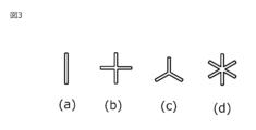
- FIG. 3 is a diagram showing the shape of a current plate of the foreign matter removing device according to the first embodiment.
- FIG. 1 is an explanatory diagram schematically showing a foreign matter removing device 1 according to the first embodiment.
- FIG. 2 is a diagram of FIG. 1 viewed from the AA side.
- the foreign matter removal device 1 is installed in a circuit through which a fluid such as water flows.
- the foreign matter removal device 1 is a device that removes foreign matter contained in an inflowing fluid and causes the fluid to flow out. It includes a foreign matter discharging means 7, a second foreign matter discharging means 8, a second foreign matter discharging means connecting portion 9, a rectifying plate 10, and the like.
- FIGS. 1 and 2 the direction of movement of the fluid flowing through the foreign matter removal device 1 is indicated by an arrow.
- the broken line shows the inner wall or the invisible part.
- the trap section 2 is a hollow cylindrical structure. When the foreign matter removal device 1 is installed in a circuit through which fluid flows, the trap section 2 is arranged to extend in the vertical direction, as illustrated in FIG.
- the trap part 2 may be made of metal such as stainless steel, brass, copper, aluminum, or steel, or may be made of polytetrafluoroethylene (Teflon (registered trademark) resin), polyvinyl chloride, polyethylene, polystyrene, polypropylene, polysulfone, isoprene.
- resin such as rubber, butadiene rubber, styrene-butadiene rubber, aromatic polyamide (such as nylon 6 or nylon 6-6), ABS (acrylonitrile-butadiene-styrene), acrylic, or carbon fiber reinforced plastic.
- the inflow section 3 constitutes a flow path for causing the fluid flowing in the circuit to flow into the trap section 2. As illustrated in FIG. 1, one end of the inflow section 3 is connected to the upper part of the trap section 2, and the other end of the inflow section 3 is connected to the circuit via piping, so that fluid flows from the circuit side in the direction of arrow B. invade.
- the outflow part 4 constitutes a flow path for causing the fluid flowing in the trap part 2 to flow out to a circuit outside the trap part 2. As illustrated in FIG. 1, one end of the outflow section 4 is connected to the trap section 2, and the other end of the outflow section 4 is connected to a circuit via piping. The internal fluid of the swirling flow flowing inside the cylindrical structure of the separation section 5, which will be described later, is caused to flow out to the circuit outside the trap section 2 via the outflow section 4.
- the inflow section 3 is configured so that the fluid flowing inside the inflow section 3 generates a swirling flow within the trap section 2, as illustrated in FIG. This configuration prevents the fluid that has flowed into the foreign matter removing device 1 from directly flowing out of the foreign matter removing device 1 from the outflow portion 4 .
- the fluid that has flowed into the trap section 2 from the inflow section 3 becomes a swirling flow that swirls inside the trap section 2 along the outer periphery of the trap section 2, which has a circular horizontal cross section as shown in FIG.
- the liquid flows down and flows out from the outflow portion 4.
- the separation section 5 is a separation member for separating the fluid flowing in from the inflow section 3 into the outer peripheral side and the center side within the trap section 2.
- the separation section 5 is a hollow cylindrical structure disposed at a predetermined position inside the trap section 2, separated from the outer periphery, and is a cylindrical member in this embodiment. Therefore, as shown in FIG. 2, the inner diameter of the separating section 5 is smaller than the inner diameter of the trap section 2 at the position where the separating section 5 is disposed. As a result, a gap (hereinafter referred to as the first foreign matter trapping part 6) is formed between the inner wall of the trap part 2 and the separation part 5. With this configuration, the fluid that has flowed into the foreign matter removal device 1 is separated in the trap section 2 into an inner swirling fluid flowing inside the separating section 5 and an outer swirling fluid flowing outside the separating section 5. be done.
- the separation section 5 is arranged below the trap section 2, as illustrated in FIG.
- the separation section 5 is disposed at the bottom of the trap section 2 and vertically below the inflow section 3 .
- the outflow section 4 is similarly arranged vertically below the inflow section 3.
- the separation part 5 is arranged at the same position in the vertical direction as the connection part of the trap part 2 to which the outflow part 4 is connected.
- the outflow portion 4 is formed to penetrate the cylindrical structure of the separation portion 5 and the trap portion 2 .
- the first foreign matter foreign matter having a higher specific gravity than the fluid, such as iron rust contained in the fluid (hereinafter referred to as the first foreign matter), is collected in the first foreign matter trapping part 6, and the inside where the first foreign matter has been removed is collected.
- the fluid flows out from the outlet 4.
- the fluid flows in a cyclone shape as a swirling flow within the trap section 2, thereby forming a vortex.
- the rotation associated with the vortex creates a centrifugal force that pushes the fluid outward. That is, the fluid inside the trap section 2 has a high pressure on the outside and a low pressure on the center side.
- foreign objects such as bubbles that have a lower specific gravity than the fluid (hereinafter referred to as second foreign objects) gather at the center of the trap section 2 due to the difference in pressure, and float due to the difference in specific gravity with the fluid. .
- the first foreign matter moves toward the outer periphery inside the trap section 2 due to such a difference in pressure, and collects at the lower part of the trap section 2 due to gravitational sedimentation.
- the first foreign matter will collect on the outside of the separation section 5 within the trap section 2. Therefore, the fluid from which not only the first foreign matter but also the second foreign matter has been appropriately removed is discharged from the outflow portion 4.
- the first foreign matter capturing section 6 captures the first foreign matter.
- the first foreign matter capturing section 6 captures the first foreign matter that has settled due to gravity and has a large specific gravity.
- the first foreign matter capturing section 6 is provided with a first foreign matter discharging means 7 extending vertically downward from the bottom of the trap section 2 .
- the first foreign matter discharging means 7 discharges the first foreign matter captured by the first foreign matter capturing section 6.
- the first foreign matter discharge means 7 is, for example, a valve, and when opened, discharges the first foreign matter captured by the first foreign matter trap 6 to the outside.
- the second foreign matter discharging means 8 discharges the second foreign matter that collects at the center of the trap section 2.
- the second foreign matter discharging means 8 is, for example, an air valve, and when opened, collects at the center of the trap section 2 and discharges the second foreign matter floating to the outside.
- the second foreign matter discharging means connection section 9 connects the second foreign matter discharging means 8 to the trap section 2.
- the second foreign matter discharge means connecting portion 9 is connected to a ceiling that is vertically above the outflow portion 4 and is the top of the inner wall of the trap portion 2 above the inflow portion 3. It is a space that opens upward at or near the center (both are referred to as the center). With this configuration, the second foreign matter that gathers at the center of the trap section 2 and floats up flows into the second foreign matter discharging means connection section 9 and floats to the second foreign matter discharging means 8.
- the rectifying plate 10 is disposed at the second foreign matter discharge means connection portion 9 and floats the second foreign matter that has flowed into the second foreign matter discharge means connection portion 9.
- the current plate 10 has a shape that divides the opening of the second foreign matter ejecting means connecting portion 9
- the rectifying plate 10 has a shape that divides the opening of the second foreign matter ejecting means connecting portion 9. It is possible to reduce the swirling flow and float the second foreign matter that has flowed into the second foreign matter discharging means connection portion 9 to the second foreign matter discharging means 8.
- the second foreign matter discharging means connection portion 9 and the rectifying plate 10 can suppress malfunction of the second foreign matter discharging means 8 due to the downward swirling flow generated in the center of the trap portion 2 .
- the foreign matter removal device As described above, according to the foreign matter removal device according to the present embodiment, it is possible to remove the first foreign matter, such as iron rust, which has a higher specific gravity than the fluid, while the second foreign matter, such as air bubbles, can be removed. Furthermore, the ability to remove foreign matter having a specific gravity lower than that of the fluid can be further improved.
Landscapes
- Cyclones (AREA)
- Degasification And Air Bubble Elimination (AREA)
- Physical Water Treatments (AREA)
Priority Applications (2)
| Application Number | Priority Date | Filing Date | Title |
|---|---|---|---|
| JP2022559901A JP7186936B1 (ja) | 2022-06-21 | 2022-06-21 | 異物除去装置 |
| PCT/JP2022/024669 WO2023248331A1 (ja) | 2022-06-21 | 2022-06-21 | 異物除去装置 |
Applications Claiming Priority (1)
| Application Number | Priority Date | Filing Date | Title |
|---|---|---|---|
| PCT/JP2022/024669 WO2023248331A1 (ja) | 2022-06-21 | 2022-06-21 | 異物除去装置 |
Publications (1)
| Publication Number | Publication Date |
|---|---|
| WO2023248331A1 true WO2023248331A1 (ja) | 2023-12-28 |
Family
ID=84388168
Family Applications (1)
| Application Number | Title | Priority Date | Filing Date |
|---|---|---|---|
| PCT/JP2022/024669 Ceased WO2023248331A1 (ja) | 2022-06-21 | 2022-06-21 | 異物除去装置 |
Country Status (2)
| Country | Link |
|---|---|
| JP (1) | JP7186936B1 (https=) |
| WO (1) | WO2023248331A1 (https=) |
Citations (4)
| Publication number | Priority date | Publication date | Assignee | Title |
|---|---|---|---|---|
| JPS5150466U (https=) * | 1974-10-16 | 1976-04-16 | ||
| JPS63144853U (https=) * | 1987-03-17 | 1988-09-22 | ||
| JP2009297676A (ja) * | 2008-06-16 | 2009-12-24 | Okano Kiko Kk | 異物粒子分離装置 |
| WO2018061513A1 (ja) * | 2016-09-30 | 2018-04-05 | パナソニックIpマネジメント株式会社 | サイクロン分離装置 |
-
2022
- 2022-06-21 WO PCT/JP2022/024669 patent/WO2023248331A1/ja not_active Ceased
- 2022-06-21 JP JP2022559901A patent/JP7186936B1/ja active Active
Patent Citations (4)
| Publication number | Priority date | Publication date | Assignee | Title |
|---|---|---|---|---|
| JPS5150466U (https=) * | 1974-10-16 | 1976-04-16 | ||
| JPS63144853U (https=) * | 1987-03-17 | 1988-09-22 | ||
| JP2009297676A (ja) * | 2008-06-16 | 2009-12-24 | Okano Kiko Kk | 異物粒子分離装置 |
| WO2018061513A1 (ja) * | 2016-09-30 | 2018-04-05 | パナソニックIpマネジメント株式会社 | サイクロン分離装置 |
Also Published As
| Publication number | Publication date |
|---|---|
| JP7186936B1 (ja) | 2022-12-09 |
| JPWO2023248331A1 (https=) | 2023-12-28 |
Similar Documents
| Publication | Publication Date | Title |
|---|---|---|
| EP2271432B1 (en) | Particle separator | |
| US20160008741A1 (en) | Fluid separator | |
| RU2608772C2 (ru) | Центробежный циклонный сепаратор | |
| US6890375B2 (en) | Cyclonic air filter with exit baffle | |
| EP2800631B1 (en) | Dynamic particle separator | |
| JPS6153094B2 (https=) | ||
| JP6985398B2 (ja) | 排気測定装置用凝縮水分離機 | |
| JP7351023B1 (ja) | 異物除去装置 | |
| EP3229933B1 (en) | Separator and method | |
| JP5803263B2 (ja) | 気液分離器 | |
| WO2023248331A1 (ja) | 異物除去装置 | |
| JP7317153B1 (ja) | 異物除去装置 | |
| JPH0647990Y2 (ja) | グリース阻集器 | |
| CN112546819A (zh) | 一种可以有效防止气体复吸液体的气液分离器 | |
| KR101652375B1 (ko) | 유정유체 분리장치 | |
| JPWO2024013885A5 (https=) | ||
| KR101847018B1 (ko) | 열교환기능을 갖는 생산수 처리장치 | |
| JP5490589B2 (ja) | 吸引回収装置 | |
| CN207072927U (zh) | 一种钻井用的高效四相分离器 | |
| CN218339064U (zh) | 水循环管路固液分离器 | |
| JP2007253048A (ja) | 防泡装置及びサイクロン型濾過装置 | |
| JP2009248078A (ja) | 油分離可能なサイクロン式濾過装置 | |
| JPH059656U (ja) | サイクロン型セパレータ | |
| JP2003225660A (ja) | 浮上物体回収装置 | |
| CN208898547U (zh) | 一种油水分离器的迷宫式稳流装置 |
Legal Events
| Date | Code | Title | Description |
|---|---|---|---|
| ENP | Entry into the national phase |
Ref document number: 2022559901 Country of ref document: JP Kind code of ref document: A |
|
| 121 | Ep: the epo has been informed by wipo that ep was designated in this application |
Ref document number: 22947894 Country of ref document: EP Kind code of ref document: A1 |
|
| NENP | Non-entry into the national phase |
Ref country code: DE |
|
| 122 | Ep: pct application non-entry in european phase |
Ref document number: 22947894 Country of ref document: EP Kind code of ref document: A1 |