WO2023243345A1 - レンズ部品およびレンズ部品を用いた車両用灯具 - Google Patents
レンズ部品およびレンズ部品を用いた車両用灯具 Download PDFInfo
- Publication number
- WO2023243345A1 WO2023243345A1 PCT/JP2023/019351 JP2023019351W WO2023243345A1 WO 2023243345 A1 WO2023243345 A1 WO 2023243345A1 JP 2023019351 W JP2023019351 W JP 2023019351W WO 2023243345 A1 WO2023243345 A1 WO 2023243345A1
- Authority
- WO
- WIPO (PCT)
- Prior art keywords
- optical system
- lens
- entrance
- optical
- exit
- Prior art date
- Legal status (The legal status is an assumption and is not a legal conclusion. Google has not performed a legal analysis and makes no representation as to the accuracy of the status listed.)
- Ceased
Links
Images












Classifications
-
- F—MECHANICAL ENGINEERING; LIGHTING; HEATING; WEAPONS; BLASTING
- F21—LIGHTING
- F21S—NON-PORTABLE LIGHTING DEVICES; SYSTEMS THEREOF; VEHICLE LIGHTING DEVICES SPECIALLY ADAPTED FOR VEHICLE EXTERIORS
- F21S41/00—Illuminating devices specially adapted for vehicle exteriors, e.g. headlamps
- F21S41/10—Illuminating devices specially adapted for vehicle exteriors, e.g. headlamps characterised by the light source
- F21S41/14—Illuminating devices specially adapted for vehicle exteriors, e.g. headlamps characterised by the light source characterised by the type of light source
- F21S41/141—Light emitting diodes [LED]
- F21S41/143—Light emitting diodes [LED] the main emission direction of the LED being parallel to the optical axis of the illuminating device
-
- F—MECHANICAL ENGINEERING; LIGHTING; HEATING; WEAPONS; BLASTING
- F21—LIGHTING
- F21S—NON-PORTABLE LIGHTING DEVICES; SYSTEMS THEREOF; VEHICLE LIGHTING DEVICES SPECIALLY ADAPTED FOR VEHICLE EXTERIORS
- F21S41/00—Illuminating devices specially adapted for vehicle exteriors, e.g. headlamps
- F21S41/10—Illuminating devices specially adapted for vehicle exteriors, e.g. headlamps characterised by the light source
- F21S41/14—Illuminating devices specially adapted for vehicle exteriors, e.g. headlamps characterised by the light source characterised by the type of light source
- F21S41/141—Light emitting diodes [LED]
- F21S41/151—Light emitting diodes [LED] arranged in one or more lines
-
- F—MECHANICAL ENGINEERING; LIGHTING; HEATING; WEAPONS; BLASTING
- F21—LIGHTING
- F21S—NON-PORTABLE LIGHTING DEVICES; SYSTEMS THEREOF; VEHICLE LIGHTING DEVICES SPECIALLY ADAPTED FOR VEHICLE EXTERIORS
- F21S41/00—Illuminating devices specially adapted for vehicle exteriors, e.g. headlamps
- F21S41/20—Illuminating devices specially adapted for vehicle exteriors, e.g. headlamps characterised by refractors, transparent cover plates, light guides or filters
-
- F—MECHANICAL ENGINEERING; LIGHTING; HEATING; WEAPONS; BLASTING
- F21—LIGHTING
- F21S—NON-PORTABLE LIGHTING DEVICES; SYSTEMS THEREOF; VEHICLE LIGHTING DEVICES SPECIALLY ADAPTED FOR VEHICLE EXTERIORS
- F21S41/00—Illuminating devices specially adapted for vehicle exteriors, e.g. headlamps
- F21S41/20—Illuminating devices specially adapted for vehicle exteriors, e.g. headlamps characterised by refractors, transparent cover plates, light guides or filters
- F21S41/24—Light guides
-
- F—MECHANICAL ENGINEERING; LIGHTING; HEATING; WEAPONS; BLASTING
- F21—LIGHTING
- F21V—FUNCTIONAL FEATURES OR DETAILS OF LIGHTING DEVICES OR SYSTEMS THEREOF; STRUCTURAL COMBINATIONS OF LIGHTING DEVICES WITH OTHER ARTICLES, NOT OTHERWISE PROVIDED FOR
- F21V5/00—Refractors for light sources
-
- F—MECHANICAL ENGINEERING; LIGHTING; HEATING; WEAPONS; BLASTING
- F21—LIGHTING
- F21V—FUNCTIONAL FEATURES OR DETAILS OF LIGHTING DEVICES OR SYSTEMS THEREOF; STRUCTURAL COMBINATIONS OF LIGHTING DEVICES WITH OTHER ARTICLES, NOT OTHERWISE PROVIDED FOR
- F21V5/00—Refractors for light sources
- F21V5/02—Refractors for light sources of prismatic shape
-
- F—MECHANICAL ENGINEERING; LIGHTING; HEATING; WEAPONS; BLASTING
- F21—LIGHTING
- F21V—FUNCTIONAL FEATURES OR DETAILS OF LIGHTING DEVICES OR SYSTEMS THEREOF; STRUCTURAL COMBINATIONS OF LIGHTING DEVICES WITH OTHER ARTICLES, NOT OTHERWISE PROVIDED FOR
- F21V5/00—Refractors for light sources
- F21V5/04—Refractors for light sources of lens shape
-
- G—PHYSICS
- G02—OPTICS
- G02B—OPTICAL ELEMENTS, SYSTEMS OR APPARATUS
- G02B17/00—Systems with reflecting surfaces, with or without refracting elements
-
- G—PHYSICS
- G02—OPTICS
- G02B—OPTICAL ELEMENTS, SYSTEMS OR APPARATUS
- G02B17/00—Systems with reflecting surfaces, with or without refracting elements
- G02B17/08—Catadioptric systems
-
- G—PHYSICS
- G02—OPTICS
- G02B—OPTICAL ELEMENTS, SYSTEMS OR APPARATUS
- G02B6/00—Light guides; Structural details of arrangements comprising light guides and other optical elements, e.g. couplings
-
- F—MECHANICAL ENGINEERING; LIGHTING; HEATING; WEAPONS; BLASTING
- F21—LIGHTING
- F21W—INDEXING SCHEME ASSOCIATED WITH SUBCLASSES F21K, F21L, F21S and F21V, RELATING TO USES OR APPLICATIONS OF LIGHTING DEVICES OR SYSTEMS
- F21W2102/00—Exterior vehicle lighting devices for illuminating purposes
- F21W2102/10—Arrangement or contour of the emitted light
- F21W2102/13—Arrangement or contour of the emitted light for high-beam region or low-beam region
- F21W2102/135—Arrangement or contour of the emitted light for high-beam region or low-beam region the light having cut-off lines, i.e. clear borderlines between emitted regions and dark regions
- F21W2102/155—Arrangement or contour of the emitted light for high-beam region or low-beam region the light having cut-off lines, i.e. clear borderlines between emitted regions and dark regions having inclined and horizontal cutoff lines
-
- F—MECHANICAL ENGINEERING; LIGHTING; HEATING; WEAPONS; BLASTING
- F21—LIGHTING
- F21Y—INDEXING SCHEME ASSOCIATED WITH SUBCLASSES F21K, F21L, F21S and F21V, RELATING TO THE FORM OR THE KIND OF THE LIGHT SOURCES OR OF THE COLOUR OF THE LIGHT EMITTED
- F21Y2115/00—Light-generating elements of semiconductor light sources
- F21Y2115/10—Light-emitting diodes [LED]
-
- F—MECHANICAL ENGINEERING; LIGHTING; HEATING; WEAPONS; BLASTING
- F21—LIGHTING
- F21Y—INDEXING SCHEME ASSOCIATED WITH SUBCLASSES F21K, F21L, F21S and F21V, RELATING TO THE FORM OR THE KIND OF THE LIGHT SOURCES OR OF THE COLOUR OF THE LIGHT EMITTED
- F21Y2115/00—Light-generating elements of semiconductor light sources
- F21Y2115/30—Semiconductor lasers
Definitions
- the present disclosure relates to a lens component and a vehicle lamp using the lens component.
- a vehicle lamp that illuminates the front of the lamp through a microlens array is known from Patent Document 1 and the like.
- the microlens array described in Patent Document 1 includes a light shielding plate between the entrance side lens array and the exit side lens array.
- a low beam light distribution pattern having a cutoff line is formed by blocking a portion of the light emitted from the light source unit by the light shielding plate.
- a part of the light emitted from the light source is blocked by the light shielding plate and is not emitted to the front of the lamp, so there is room for improvement in light utilization efficiency.
- the present inventor studied a configuration in which a portion of the light emitted from the light source is emitted forward without being blocked. At the same time, the inventors also considered a configuration that can be easily manufactured.
- the light source unit described in Patent Document 1 is composed of a light source and an optical system placed in front of the light source, and the light from the light source is made into parallel light by the front optical system and sent to the incident side lens array. It is incident.
- a part of the light emitted from the front optical system may not enter the entrance lens array, and there is room for improvement in light utilization efficiency.
- One of the objects of the present disclosure is to provide a lens component that can be easily manufactured and a vehicle lamp using the lens component while increasing light utilization efficiency.
- Another object of the present disclosure is to provide a lens component and a vehicular lamp using the lens component that can form a light distribution pattern with a bright central portion where higher brightness is required while increasing light utilization efficiency. Let's do one.
- the lens component according to the first aspect of the present disclosure includes: Equipped with multiple first optical systems, Each of the plurality of first optical systems is formed between an entrance side lens part having a first entrance surface, an exit side lens part having a first exit surface, and the first entrance surface and the first exit surface. and a reflecting surface that reflects the light incident on the incident side lens portion toward the exit side lens portion, The plurality of first optical systems are arranged along the first direction, The plurality of first optical systems are provided with each of the reflecting surfaces oriented along the first direction.
- the vehicle lamp according to the second aspect of the present disclosure includes: at least one light source; The above lens parts and A plurality of primary lenses that output the light emitted from the light source as parallel light to the lens component, Each of the plurality of primary lenses is arranged to face at least one of the first optical systems.
- the lens component according to the third aspect of the present disclosure includes: at least one first optical system; at least one second optical system;
- the first optical system includes a first entrance side lens section, a first exit side lens section, a first entrance surface of the first entrance side lens section, and a first exit surface of the first exit side lens section. a first surface extending through the focal point of the first exit surface formed in the first surface, and a second surface extending from the first surface to the first entrance surface
- the second optical system includes a second entrance side lens section, a second exit side lens section, a second entrance surface of the second entrance side lens section, and a second exit surface of the second exit side lens section.
- a first cut line forming portion is configured by a first boundary between the first surface and the second surface
- a second cut line forming portion is configured by a second boundary between the third surface and the fourth surface
- a vehicle lamp includes: at least one light source; The above lens parts and A plurality of primary lenses that output the light emitted from the light source as parallel light to the lens component,
- the lens component includes a plurality of the first optical systems and a plurality of the second optical systems, Each of the plurality of first optical systems forms an optical unit together with the second optical system arranged such that the fourth surface faces the first optical system,
- Each of the plurality of primary lenses is arranged to face at least one of the optical units.
- the present disclosure it is possible to provide a lens component and a vehicle lamp using the lens component that can be easily manufactured while increasing light utilization efficiency.
- the lens component and a vehicle lamp using the lens component that can form a light distribution pattern in which the central portion where higher brightness is required is brighter while increasing light utilization efficiency.
- FIG. 1 is a schematic cross-sectional view showing the configuration of a vehicle lamp according to a first embodiment of the present disclosure.
- FIG. 2 is a perspective view showing the configuration of optical components arranged inside the vehicle lamp.
- FIG. 3 is a cross-sectional view of FIG. 2;
- FIG. 3 is a diagram showing a light distribution pattern formed by a vehicle lamp.
- FIG. 7 is a schematic cross-sectional view showing another example of the configuration of the vehicle lamp.
- FIG. 7 is a plan view showing another example of the configuration of the primary lens and lens components.
- FIG. 7 is a front view showing another example of the configuration of the primary lens and lens components.
- FIG. 7 is a perspective view showing another example of the configuration of two first optical systems facing one primary lens.
- FIG. 9 is a plan view of FIG.
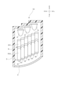
- FIG. 2 is a schematic cross-sectional view showing the configuration of a vehicle lamp according to a second embodiment of the present disclosure.
- FIG. 2 is a cross-sectional view showing the configuration of a light source, a primary lens, and an optical unit.
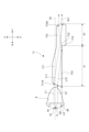
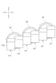
- FIG. 2 is a perspective view showing the configuration of two optical units facing one primary lens. It is a sectional view showing an optical unit.
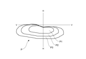
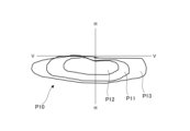
- FIG. 3 is a diagram showing a light distribution pattern formed by a vehicle lamp.
- FIG. 3 is an explanatory diagram of steps in a method for manufacturing an optical unit.
- FIG. 3 is an explanatory diagram of steps in a method for manufacturing an optical unit.
- FIG. 3 is a side view showing an optical unit in which a first optical system and a second optical system are joined.
- FIG. 7 is a schematic cross-sectional view showing another example of the configuration of the vehicle lamp.
- FIG. 7 is a front view showing another primary lens and lens components of the vehicle lamp.
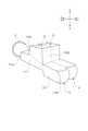
- FIG. 7 is a perspective view showing another example of the configuration of the optical unit.
- 23 is a cross-sectional view showing the configuration of the light source, primary lens, and optical unit in FIG. 22.
- FIG. 23 is a plan view showing the configuration of the primary lens and optical unit of FIG. 22.
- FIG. 23 is a diagram showing a light distribution pattern formed by the vehicle lamp of FIG. 22.
- arrow U indicates the upward direction of the illustrated structure.
- Arrow D indicates the downward direction of the illustrated structure.
- Arrow F indicates the forward direction of the illustrated structure.
- Arrow B indicates the rearward direction of the illustrated structure.
- Arrow R indicates the right direction of the illustrated structure.
- Arrow L indicates the left direction of the illustrated structure.
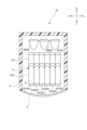
- FIG. 1 illustrates the configuration of a vehicle lamp 1 according to a first embodiment of the present disclosure.
- the vehicle lamp 1 includes an outer lens 2 and a housing 3.
- a lamp chamber 4 is formed by the outer lens 2 and the housing 3.
- the vehicle lamp 1 includes a plurality of light sources 5 (FIG. 3), a plurality of primary lenses 6, and a lens component 7 in a light chamber 4.
- each light source 5 is mounted on a substrate 51 and arranged facing forward.
- the light source 5 for example, an LED (Light Emitting Diode) or an LD (Laser Diode) can be used.
- the light emitted from the light source 5 passes through one primary lens 6 and a part of the lens component 7, and is emitted toward the front of the vehicle lamp 1.
- the primary lens 6 converts the light emitted from the light source 5 into parallel light and makes it enter the lens component 7.
- a collimating lens, an aplanat lens, a Fresnel lens, etc. can be used as the primary lens 6, a collimating lens, an aplanat lens, a Fresnel lens, etc. can be used as the primary lens 6, a collimating lens, an aplanat lens, a Fresnel lens, etc. can be used.
- the primary lens 6 is an optical component made of, for example, a transparent resin material or a glass material.
- the primary lens 6 has a first entrance part 61 and a second entrance part 62.
- the first incidence section 61 is provided at a position facing the light source 5.
- the second entrance section 62 is provided as a vertical wall surrounding the first entrance section 61 .
- Lights L1 and L2 that have entered the first incidence section 61 from the light source 5 are refracted at the first incidence section 61 so as to become parallel lights with the optical axis Ax.
- the light L3 that has entered the second incident section 62 from the light source 5 is reflected by the reflective surface 63 so as to become parallel light with the optical axis Ax.
- the optical axis Ax is a virtual straight line extending from the center point of the light emitting surface of the light source 5 in the longitudinal direction of the vehicle lamp 1.
- the lens component 7 is an optical component made of, for example, a transparent resin material or a glass material. As illustrated in FIGS. 1 and 2, the lens component 7 includes a plurality of first optical systems 71 (71A to 71F). The plurality of first optical systems 71 are integrated with each other. For example, the plurality of first optical systems 71 are integrally molded by molding a transparent resin or glass material. Alternatively, after each first optical system 71 is molded by molding, the plurality of first optical systems 71 may be joined using an adhesive, a pin, or the like. The size of the first optical system 71 (each lens) is arbitrary, but preferably about 0.5 to 10 mm square when viewed from the front in the irradiation direction.
- the plurality of first optical systems 71 are arranged side by side in contact with each other in a direction (in the left-right direction in the example of FIG. 1) orthogonal to the light emission direction (optical axis Ax of the light source 5).
- the left-right direction in which the plurality of first optical systems 71 are arranged is an example of the first direction.
- the plurality of first optical systems 71 are arranged in the same position in the longitudinal direction of the vehicle, and are arranged side by side in the width direction of the vehicle.
- the two first optical systems 71 are arranged to face one primary lens 6.
- two first optical systems 71A and 71B face the primary lens 6A
- two first optical systems 71C and 71D face the primary lens 6B
- two first optical systems 71E and 71F face the primary lens 6A. It faces the lens 6C.
- the parallel light emitted from one primary lens 6 enters two opposing first optical systems 71, passes through the two first optical systems 71, and is emitted toward the front of the vehicle lamp 1. .
- the first optical system 71 has an entrance side lens section 711 and an exit side lens section 712.
- the entrance side lens section 711 has a first entrance surface 711A into which the light from the primary lens 6 enters.
- the exit side lens portion 712 has a first exit surface 712A through which light that has passed through the inside of the first optical system 71 exits toward the outer lens 2.
- the entrance side lens section 711 and the exit side lens section 712 are provided on a common optical axis Ax1 and face each other.
- the optical axis Ax1 of the first optical system 71 is parallel to the optical axis Ax of the light source 5.
- the entrance side lens section 711 and the exit side lens section 712 each have a convex lens shape.
- the first optical system 71 further has a first surface 713 and a second surface 714 between the first entrance surface 711A and the first exit surface 712A.
- a cut line forming portion is configured by a boundary portion 715 between the first surface 713 and the second surface 714.
- the first surface 713 extends through the focal point of the first exit surface 712A.
- the first surface 713 is a surface that extends in a direction perpendicular to the optical axis Ax1 through the focal point of the first output surface 712A, and is also a surface that extends in the vertical and horizontal directions.
- the second surface 714 extends from the first surface 713 to the first entrance surface 711A.
- the plurality of first optical systems 71 are provided with each second surface 714 oriented along a first direction (left-right direction in the example of FIG. 3), which is the arrangement direction of the plurality of first optical systems 71.
- each second surface 714 is a surface extending in the front-back direction and the left-right direction, and is parallel to the first direction. Further, in this example, the plurality of second surfaces 714 are located on the same plane (that is, flush with each other).
- the expression "the reflective surface is along the first direction" used in this specification means that the reflective surface is not only parallel to the first direction but also located within a range of less than plus or minus 45 degrees of the first direction. A configuration parallel to the direction may also be included.
- the second surface 714 functions as a reflective surface that reflects the light incident on the entrance side lens section 711 toward the exit side lens section 712. Specifically, no other optical system is formed below the first optical system 71, and the second surface 714 is in contact with an air layer. Due to the difference in refractive index between the first optical system 71 and the air layer, the second surface 714 is configured to totally reflect the light that has entered the incident side lens section 711 and reached the second surface 714.
- the light L11 that is emitted from the primary lens 6 and enters the entrance side lens section 711 of the first optical system 71 is directed toward the exit side lens section 712.
- the light advances and is emitted from the first exit surface 712A of the exit side lens section 712.
- light L12 that would not otherwise enter the exit lens section 712 can be reflected by the second surface 714 and can be made to enter the exit lens section 712 .
- the plurality of first optical systems 71 are provided with the second surface 714 aligned in the first direction, and the second surface 714 is not covered by another first optical system.
- the first optical systems 71 are formed in a direction along the arrangement plane of the plurality of first optical systems 71 so as to prevent the first optical systems 71 from collapsing. This makes it easy to polish the second surface 714, and the polishing also improves reflection efficiency. As a result, lens components can be manufactured easily while increasing light utilization efficiency.
- the entrance side lens section 711 and the exit side lens section 712 of the first optical system 71 are integrally molded by molding.
- the entrance side lens part 711 and the exit side lens part 712 are molded separately, there is no misalignment due to assembly such as positional deviation between the first entrance surface and the first exit surface 712A of 711A.
- first optical systems 71 are integrally formed by mold molding, compared to the case where the second surface 714 of each first optical system 71 is separately attached to a polishing machine and polished, Since the plurality of integrated first optical systems 71 can be attached to a polishing machine and the plurality of second surfaces 714 can be polished, the efficiency of the polishing operation is improved. In particular, when the plurality of second surfaces 714 of the plurality of first optical systems 71 are flush, the plurality of second surfaces 714 can be polished all at once, which further improves the efficiency of the polishing work.
- the vehicle lamp 1 includes a plurality of primary lenses 6, and the parallel light from the primary lenses 6 can be made to enter at least one first optical system 71.
- the size of the primary lens 6 can be made smaller, and the space for arranging the primary lens 6 can be saved. Can be made smaller.
- the primary lens 6 can be arranged according to the position of the first optical system 71, the degree of freedom in arrangement of the first optical system 71 is improved.
- two first optical systems 71 face one primary lens 6.
- the number of parts of the primary lens 6 can be reduced compared to the case where one first optical system 71 is opposed to one primary lens 6.
- light that is emitted from the primary lens 6 and is shifted from one of the two first optical systems 71 in the left-right direction and does not enter one of the first optical systems 71 enters the other of the two first optical systems 71. . Therefore, the light emitted from the primary lens 6 can be effectively utilized in the light distribution pattern, increasing the light utilization efficiency.
- the lens component 7 may be configured such that the shapes of the first incident surfaces 711A are different when at least two first optical systems 71 are compared.
- the first entrance surface 711A of at least one first optical system 71 among the plurality of first optical systems 71 has a first shape
- the first entrance surface 711A of at least one other first optical system 71 has a first shape.
- the entrance surface 711A may have a second shape different from the first shape.
- the first entrance surfaces 711A of the first optical system 71A and the first optical system 71B have the first radius of curvature R1
- the first entrance surfaces 711A of the first optical system 71C and the first optical system 71D have the first curvature radius R1.
- It has a second radius of curvature R2 different from the radius R1
- the first entrance surface 711A of the first optical system 71E and the first optical system 71F has a third radius of curvature different from the first radius of curvature R1 and the second radius of curvature R2.
- Lens component 7 may be configured to have R3.
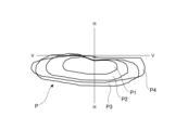
- FIG. 4 illustrates a low beam light distribution pattern P formed by the vehicle lamp 1.
- the first light distribution pattern P1 is a pattern formed by light emitted from the first optical system 71A and the first optical system 71B.
- the second light distribution pattern P2 is a pattern formed by the light emitted from the first optical system 71C and the first optical system 71D.
- the third light distribution pattern P3 is a pattern formed by the light emitted from the first optical system 71E and the first optical system 71F.
- the light distribution pattern P is formed by overlapping a first light distribution pattern P1, a second light distribution pattern P2, and a third light distribution pattern P3.
- the projected image formed by the first optical system 71C and the first optical system 71D is It is larger than the projected image formed by the first optical system 71A and the first optical system 71B, and smaller than the projected image formed by the first incident surface 711A of the first optical system 71E and the first optical system 71F. That is, as shown in FIG. 4, the second light distribution pattern P2 can be formed larger than the first light distribution pattern P1 and smaller than the third light distribution pattern P3.
- the shape of the first entrance surface 711A is changed by changing the radius of curvature of the first entrance surface 711A, but the shape is not limited to this.
- the lens component 7 is such that when at least two first optical systems 71 are compared, the ratio (A1:B1) between the entrance lens thickness A1 and the exit lens thickness B1 as illustrated in FIG. 3 is different. may be configured.
- at least one first optical system among the plurality of first optical systems 71 is formed such that the ratio of the entrance lens thickness A1 to the exit lens thickness B1 is a first value
- the ratio of the other at least One first optical system 71 may be formed such that the ratio of the entrance lens thickness A1 to the exit lens thickness B1 is a second value different from the first value.
- the incident lens thickness A1 is the thickness from the first incident surface 711A of the incident side lens portion 711 to the boundary portion 715.
- the exit lens thickness B1 is the thickness from the first exit surface 712A of the exit side lens portion 712 to the boundary portion 715.
- thickness means the thickness in the direction along the optical axis Ax (in the example of FIG. 3, the front-rear direction). More specifically, the thickness of the incident side lens portion 711 is the dimension from the most protruding portion of the first incident surface 711A of the incident side lens portion 711 to the boundary portion 715 on the optical axis Ax. The thickness of the exit lens section 712 is the dimension from the boundary on the optical axis Ax to the most protruding portion of the first exit surface 712A of the exit lens section 712.
- the ratio of the lens thicknesses of the first optical system 71C and the first optical system 71D is larger than the ratio of the lens thicknesses of the first optical system 71A and the first optical system 71B, and the first optical system 71E and the first optical system
- the lens component 7 can be formed to have a smaller ratio than the first entrance surface 711A of the system 71F.
- the projected image formed by the first optical system 71C and the first optical system 71D is larger than the projected image formed by the first optical system 71A and the first optical system 71B, and 71E and the first incident surface 711A of the first optical system 71F. That is, a low beam light distribution pattern P as shown in FIG. 4 can be formed.
- the lens component 7 is such that both the shape of the first entrance surface 711A and the ratio (A1:B1) of the entrance lens thickness A1 and the exit lens thickness B1 are different. may be configured.
- the plurality of first optical systems 71 are shifted in the longitudinal direction of the vehicle and They may be arranged side by side in the direction.
- the vehicle lamp 1 is a headlamp mounted on the front left side of the vehicle
- the plurality of first optical systems 71 (71A to 71F) are positioned toward the rear of the vehicle toward the left side of the vehicle. can be placed.
- the vehicular lamp 1 can have a shape that matches the shape of the vehicle in which it is mounted.
- the entrance lens thickness A1 is different between at least two first optical systems 71, and when the vehicle lamp 1 is mounted on a vehicle, a plurality of The first optical system 71 may be arranged side by side in the width direction of the vehicle, with the first output surface 712A being shifted in the front-rear direction of the vehicle.
- the plurality of first optical systems 71 (71A to 71F) all have different entrance lens thicknesses A1
- the plurality of first optical systems 71 (71A to 71F) all have different entrance lens thicknesses A1
- the plurality of first optical systems 71 (71A to 71F) all have different entrance lens thicknesses A1.
- the first output surface 712A of the one optical system 71 may be positioned toward the rear of the vehicle toward the left side of the vehicle.
- the vehicle lamp 1 can have a shape that matches the shape of the vehicle in which it is mounted. .
- the size of the vehicle lamp 1 in the longitudinal direction of the vehicle can be reduced compared to the configuration shown in FIG. can.
- the plurality of first optical systems 71 are shifted in the vertical direction of the vehicle, while being shifted in the width direction of the vehicle. may be arranged side by side.
- the plurality of first optical systems 71 may be arranged so as to be positioned upward toward the left side of the vehicle.
- the second surface 714 of each first optical system 71 is a surface extending in the front-rear direction and the left-right direction
- the second surface 714 of each first optical system 71 is a surface extending in the front-rear direction and the left-right direction.
- the direction is parallel to a direction located within a range of less than -45 degrees from the direction (in the example, the direction tilts upward toward the left).
- the second surfaces 714 do not have to be located on the same plane.
- the vehicle lamp 1 can have a shape that matches the shape and design of the vehicle in which it is mounted.
- the plurality of first optical systems 71 may be arranged so as to have an arrangement that is a combination of the arrangement shown in FIG. 7 and the arrangement shown in FIG. 5 or 6.
- the lens component 7 may further include a second optical system 72 in addition to the first optical system 71, as illustrated in FIGS. 8 and 9. Note that FIGS. 8 and 9 only show the configuration of one primary lens and two first optical systems facing the primary lens.
- the lens component 7 includes a plurality of first optical systems 71 and a plurality of second optical systems 72.
- the first optical system 71 and the second optical system 72 are integrated.
- the first optical system 71 and the second optical system 72 may be molded separately and then joined using an adhesive, a pin, or the like.
- the second optical system 72 and the second optical system 72 may be integrally molded using a mold.
- the second optical system 72 is arranged above the second optical system 72 so as to face the surface opposite to the second surface 714 of the first optical system 71.
- the second optical system 72 has a second entrance surface 72A and a second exit surface 72B.
- the light L21 from the primary lens 6 is incident on the second entrance surface 72A.
- the light that has passed through the second optical system 72 is emitted toward the outer lens 2 from the second exit surface 72B.
- the second entrance surface 72A is arranged in a direction (in the direction intersecting the direction of the optical axis Ax2 of the second optical system 72 and the stacking direction (vertical direction in the example of FIG. 10) in which the first optical system 71 and the second optical system 72 are stacked. In the example of FIG. 10, it is inclined so that the light incident on the second entrance surface 72A is refracted toward the first optical system 71 when viewed from the left and right directions. Specifically, the second entrance surface 72A is inclined downward with respect to the vertical surface.
- the second entrance surface 72A is curved when viewed from the stacking direction (vertical direction in the figure), as illustrated in FIG. Specifically, the second entrance surface 72A is curved so as to be convex toward the front with respect to the horizontal plane.
- the primary lens 6 is larger than the opposing first optical system 71, a part of the light emitted from the primary lens 6 will not be able to enter the first optical system 71, and the light emitted from the primary lens 6 will not be able to enter the first optical system 71. It cannot be used effectively for light distribution patterns.
- the lens component 7 according to the first embodiment has the second optical system 72, a part of the light (light L21) emitted from the primary lens 6 enters the first optical system 71. Even if this is not the case, a part of the light enters the second optical system 72. Thereby, the light emitted from the primary lens 6 can be effectively utilized in the light distribution pattern, increasing the light utilization efficiency. Furthermore, since the primary lens 6 can be made larger, the parallelism of the parallel light emitted from the primary lens 6 can be increased.
- the second incident surface 72A of the second optical system 72 refracts the incident light downward toward the first optical system 71, the second incident surface 72A is formed by the second optical system 72, as illustrated in FIG.
- the fourth light distribution pattern P4 can be projected below the H line. Thereby, the fourth light distribution pattern P4 can be overlapped with the first light distribution pattern P1, the second light distribution pattern P2, and the third light distribution pattern P3 formed by the first optical system 71.
- the fourth light distribution pattern P4 can be formed as a diffused light distribution pattern. Thereby, a low beam light distribution pattern P that spreads in the left-right direction can be formed.
- the plurality of first optical systems 71 are arranged side by side in the left-right direction while being in contact with each other.
- the plurality of first optical systems 71 may be arranged side by side in the left-right direction while being separated from each other.
- two first optical systems 71 face one primary lens 6.
- the vehicle lamp 1 may be arranged such that one primary lens 6 faces one first optical system 71 or three or more first optical systems 71.
- the second surface 714 of the first optical system 71 functions as a reflective surface due to the difference in refractive index from the air layer.
- the second surface 714 may function as a reflective surface by forming a reflective film or the like on the second surface 714 of the first optical system 71.
- FIG. 12 illustrates the configuration of a vehicle lamp 10 according to a second embodiment of the present disclosure.
- the vehicle lamp 10 includes an outer lens 2 and a housing 3.
- a lamp chamber 4 is formed by the outer lens 2 and the housing 3.
- the vehicle lamp 10 includes a plurality of light sources 5 (see FIG. 13), a plurality of primary lenses 6, and a lens component 8 in a light chamber 4.
- each light source 5 is mounted on a substrate 51 and arranged facing forward.
- the light source 5 for example, an LED (Light Emitting Diode) or an LD (Laser Diode) can be used.
- the light emitted from the light source 5 passes through one primary lens 6 and a part of the lens component 8, and is emitted toward the front of the vehicle lamp 10.
- the primary lens 6 converts the light emitted from the light source 5 into parallel light and makes it enter the lens component 8 .
- a collimating lens, an aplanat lens, a Fresnel lens, etc. can be used as the primary lens 6, a collimating lens, an aplanat lens, a Fresnel lens, etc. can be used as the primary lens 6, a collimating lens, an aplanat lens, a Fresnel lens, etc. can be used.
- the primary lens 6 is an optical component made of, for example, a transparent resin material or a glass material.
- the primary lens 6 has a first entrance section 61 and a second entrance section 62.
- the first incidence section 61 is provided at a position facing the light source 5.
- the second entrance section 62 is provided as a vertical wall surrounding the first entrance section 61 .
- the light L31 that has entered the first incidence section 61 from the light source 5 is refracted at the first incidence section 61 so as to become parallel light with the optical axis Ax.
- the light L32 that has entered the second incident section 62 from the light source 5 is reflected by the reflecting surface 63 so as to become parallel light with the optical axis Ax.
- the optical axis Ax is a virtual straight line extending from the center point of the light emitting surface of the light source 5 in the front-rear direction of the vehicle lamp 10.
- the lens component 8 is an optical component made of, for example, a transparent resin material or a glass material.
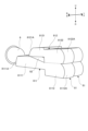
- the lens component 8 has a plurality of optical units 81, as illustrated in FIG.
- the plurality of optical units 81 are arranged side by side in a direction (left-right direction in the example of FIG. 12) perpendicular to the light emission direction (optical axis Ax of the light source 5) in a state in which they are in contact with each other.
- the plurality of optical units 81 are arranged in the same position in the longitudinal direction of the vehicle, and are arranged side by side in the width direction of the vehicle.
- the two optical units 81 are arranged to face one primary lens 6.
- two optical units 81A and 81B face the primary lens 6A
- two optical units 81C and 81D face the primary lens 6B
- two optical units 81E and 81F face the primary lens 6C.
- the parallel light emitted from one primary lens 6 enters the two optical units 81, passes through the two optical units 81, and is emitted toward the front of the vehicle lamp 10.
- each optical unit 81 includes a first optical system 811 and a second optical system 812.
- the first optical system 811 and the second optical system 812 are integrated.
- the size of the first optical system 811 is arbitrary, but preferably about 0.5 to 10 mm square when viewed from the front in the irradiation direction.
- the size of the second optical system 812 is arbitrary, but preferably about 0.5 to 10 mm square when viewed from the front in the irradiation direction.
- the first optical system 811 has a first entrance side lens section 8111 and a first exit side lens section 8112.
- the first entrance side lens section 8111 has a first entrance surface 8111A into which the light from the primary lens 6 enters.
- the first exit-side lens portion 8112 has a first exit surface 8112A through which the light that has passed through the inside of the first optical system 811 exits toward the outer lens 2.
- the first entrance side lens section 8111 and the first exit side lens section 8112 are provided on a common optical axis Ax1 and face each other.
- the optical axis Ax1 of the first optical system 811 is parallel to the optical axis Ax of the light source 5.
- the first entrance side lens section 8111 and the first exit side lens section 8112 each have a convex lens shape.
- the first optical system 811 further has a first surface 8113 and a second surface 8114 between the first entrance surface 8111A and the first exit surface 8112A.
- the first surface 8113 extends through the focal point of the first exit surface 8112A.
- the second surface 8114 extends from the first surface 8113 to the first entrance surface 8111A.
- the first surface 8113 is a surface that extends in a direction perpendicular to the optical axis Ax1 through the focal point of the first output surface 8112A, and is also a surface that extends in the vertical and horizontal directions.
- the second surface 8114 is a surface extending in the front-back direction and the left-right direction.
- a first cut line forming portion is configured by a first boundary portion 8115 between the first surface 8113 and the second surface 8114.
- the second surface 8114 functions as a reflective surface that reflects the light incident on the first entrance side lens section 8111 toward the first exit side lens section 8112.
- no other optical system is formed below the first optical system 811, and the second surface 8114 is in contact with the air layer. Due to the difference in refractive index between the first optical system 811 and the air layer, the second surface 8114 is configured to totally reflect the light that has entered the first incident side lens portion 8111 and reached the second surface 8114. .
- the first optical system 811 configured in this way, as illustrated in FIG.
- the light advances toward the first exit lens section 8112 and is emitted from the first exit surface 8112A of the first exit lens section 8112. Furthermore, among the light that has entered the first incident side lens section 8111 , light L42 that would not otherwise be incident on the first exit side lens section 8112 is also reflected by the second surface 8114 and transmitted to the first exit side lens section 8112 . It can be made incident.
- the second optical system 812 has a second entrance side lens section 8121 and a second exit side lens section 8122.
- the second entrance side lens section 8121 has a second entrance surface 8121A into which the light from the primary lens 6 enters.
- the second entrance surface 8121A may be formed such that its radius of curvature is smaller than the radius of curvature of the first entrance surface 8111A.
- the second exit side lens portion 8122 has a second exit surface 8122A through which the light that has passed through the second optical system 812 exits toward the outer lens 2.
- the second entrance side lens section 8121 and the second exit side lens section 8122 are provided on the common optical axis Ax2 and face each other.
- the optical axis Ax2 of the second optical system 812 is parallel to the optical axis Ax of the light source 5.
- the second entrance side lens section 8121 and the second exit side lens section 8122 each have a convex lens shape.
- the second optical system 812 further has a third surface 8123 and a fourth surface 8124 between the second entrance surface 8121A and the second exit surface 8122A.
- the third surface 8123 extends through the focal point of the second entrance surface 8121A.
- the fourth surface 8124 extends from the third surface 8123 to the second entrance surface 8121A.
- the third surface 8123 is a surface that extends perpendicularly to the optical axis Ax2 through the focal point of the second entrance surface 8121A, and is also a surface that extends in the vertical and horizontal directions.
- the fourth surface 8124 is a surface extending in the front-rear direction and the left-right direction.
- a second boundary portion 8125 between the third surface 8123 and the fourth surface 8124 constitutes a second cut line forming portion.
- the second optical system 812 is arranged above the first optical system 811 so that the fourth surface 8124 faces the first optical system 811.
- the fourth surface 8124 functions as a reflective surface that reflects the light incident on the second entrance side lens section 8121 toward the second exit side lens section 8122.
- a cavity 82 is provided between the first optical system 811 and the second optical system 812.
- the cavity 82 is formed by the first optical system 811 , the third surface 8123 of the second optical system 812 , and the fourth surface 8124 of the second optical system 812 .
- An arbitrary medium such as air exists inside the cavity 82 .
- the medium may be a low refractive index material having a lower refractive index than the refractive index of the first optical system 811 and the second optical system 812.
- the cavity 82 may be a sealed closed area or an unsealed open area.
- the cavity 82 is an open area that is open in the left-right direction. Due to the difference in refractive index between the second optical system 812 and the cavity 82, a part of the fourth surface 8124 forming the cavity 82 enters the second entrance side lens section 8121 and reaches the fourth surface 8124. Constructed to completely reflect light.
- the light advances toward the second exit lens section 8122 and is emitted from the second exit surface 8122A of the second exit lens section 8122. Furthermore, among the light that has entered the second incident side lens section 8121 , light L52 that would not otherwise be incident on the second exit side lens section 8122 is also reflected by the fourth surface 8124 and transmitted to the second exit side lens section 8122 . It can be made incident.
- each optical unit 81 has a ratio (A2:B2) of the second entrance lens thickness A2 of the second optical system 812 and the second exit lens thickness B2, which is the same as the first entrance lens thickness A1 of the first optical system 811. It is configured to be smaller than the ratio (A1:B1) of the thickness of one exit lens B1.
- the first optical system 811 is formed such that the ratio (A1:B1) of the first entrance lens thickness A1 to the first exit lens thickness B1 is, for example, 2:1.
- the second optical system 812 is formed such that the ratio (A2:B2) of the second entrance lens thickness A2 and the second exit lens thickness B2 is, for example, 1.3 to 1.5:1. .
- first entrance lens thickness A1 is the thickness from the first entrance surface 8111A of the first entrance side lens portion 8111 to the first boundary portion 8115.
- the first exit lens thickness B1 is the thickness from the first exit surface 8112A of the first exit side lens portion 8112 to the first boundary portion 8115.
- the second entrance lens thickness A2 is the thickness from the second entrance surface 8121A of the second entrance side lens portion 8121 to the second boundary portion 8125.
- the second exit lens thickness B2 is the thickness from the second exit surface 8122A of the second exit side lens portion 8122 to the second boundary portion 8125.
- thickness means the thickness in the direction along the optical axis Ax (in the example of FIG. 15, the front-rear direction). More specifically, the thickness of the entrance lens section is the dimension from the most protruding part of the entrance surface of the entrance lens section to the boundary on the optical axis Ax. The thickness of the exit lens section is the dimension from the boundary on the optical axis Ax to the most protruding portion of the exit surface of the exit lens section.
- the primary lens 6 is larger than the opposing first optical system 811, a part of the light emitted from the primary lens 6 will not be able to enter the first optical system 811, and the light emitted from the primary lens 6 will not be able to enter the first optical system 811. It cannot be used effectively for light distribution patterns.
- the optical unit 81 includes the second optical system 812 in addition to the first optical system 811, so that the light is emitted from the primary lens 6 and sent to the first optical system.
- Lights L51 and L52 that do not enter the second optical system 811 enter the second optical system 812. Therefore, the light emitted from the primary lens 6 can be effectively utilized in the light distribution pattern, increasing the light utilization efficiency.
- the ratio (A2:B2) between the second entrance lens thickness A2 and the second exit lens thickness B2 of the second optical system 812 is the same as the first entrance lens thickness A1 of the first optical system 811 and the first It is smaller than the ratio (A1:B1) of the exit lens thickness B1. Therefore, compared to the projected image formed by the first optical system 811, the projected image formed by the second optical system 812 can be made smaller.
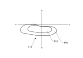
- the second light distribution pattern P12 formed by the second optical system 812 is located at the center of the first light distribution pattern P11 formed by the first optical system 811. are arranged so that they overlap. Thereby, it is possible to form a low beam light distribution pattern P10 in which the central portion where higher brightness is required is brighter.
- the second optical system 812 is arranged such that the fourth surface 8124 faces the first optical system 811. That is, the second optical system 812 is arranged above the first optical system 811. In the second optical system 812, the ratio (A2:B2) between the second entrance lens thickness A2 and the second exit lens thickness B2 is small, and crosstalk is likely to occur. Specifically, the light that is incident on the second optical system 812 and reflected by the fourth surface 8124 may be emitted from the upper surface of the second exit side lens section 8122. However, in the optical unit 81 of the second embodiment, since the second optical system 812 is arranged above the first optical system 811, the light emitted from the upper surface of the second exit side lens section 8122 is transmitted to the first optical system 812. It can be prevented from entering the first exit side lens portion 8112 of the system 811. Thereby, it is possible to suppress the influence of crosstalk caused by the second optical system 812 on the first optical system 811 .
- two optical units 81 face one primary lens 6.
- light that is emitted from the primary lens 6 and is shifted from one of the two optical units 81 in the left-right direction and does not enter one of the optical units 81 enters the other of the two optical units 81. Therefore, the light emitted from the primary lens 6 can be effectively utilized in the light distribution pattern, increasing the light utilization efficiency.
- the second exit lens thickness B2 of the second optical system 812 is the same as the first exit lens thickness B1 of the first optical system 811, and the second The second entrance lens thickness A2 of the optical system 812 may be configured to be smaller than the first entrance lens thickness A1 of the first optical system 811.
- the second entrance lens thickness A2 of the second optical system 812 is made smaller than the first entrance lens thickness A1 of the first optical system 811.
- the ratio (A2:B2) between the lens thickness A2 and the second exit lens thickness B2 can be easily reduced.
- the first optical system 811 and the second optical system 812 may be integrated by being joined.
- a plurality of first optical systems 811 are integrally molded
- a plurality of second optical systems 812 are integrally molded
- a plurality of first optical systems 811 are integrally molded.
- the lens component 8 can be manufactured by joining the plurality of molded second optical systems 812.
- a plurality of first optical systems 811 constituting a plurality of optical units 81 are formed by molding a transparent resin or a glass material using a mold M1 and a mold M2. Molded integrally.
- FIG. 17 a plurality of first optical systems 811 constituting a plurality of optical units 81 are formed by molding a transparent resin or a glass material using a mold M1 and a mold M2. Molded integrally.
- a plurality of second optical systems 812 constituting a plurality of optical units 81 are formed by molding a transparent resin or a glass material using a mold M3 and a mold M4. Molded integrally. As illustrated in FIG. 19, a plurality of integrally molded first optical systems 811 and a plurality of integrally molded second optical systems 812 are connected, with a cavity 82 formed between them. Attach them together using adhesive.
- the adhesive is preferably a transparent adhesive that has the same refractive index as the first optical system 811 and the second optical system 812. Note that they may be joined using pins or the like instead of adhesive.
- the reflective surface which is the fourth surface 8124 of the second optical system 812 that forms the cavity 82, can be polished before being joined to the first optical system 811. Therefore, the fourth surface 8124 can be easily polished and the reflection efficiency of the reflective surface can be improved.
- the entrance and exit surfaces of each optical system are integrally molded, unlike methods in which the entrance and exit lens sections are molded separately, there is no misalignment between the entrance and exit surfaces during assembly. No misalignment occurs.
- the plurality of optical units 81 are shifted in the longitudinal direction of the vehicle and They may be arranged side by side in the direction.
- the plurality of optical units 81 may be arranged so as to be positioned toward the rear of the vehicle toward the left side of the vehicle.
- the plurality of optical units 81 are shifted in the vertical direction of the vehicle and They may be arranged side by side in the direction.
- the plurality of optical units 81 may be arranged so as to be positioned upward toward the left side of the vehicle.
- the optical unit 81 may further include a third optical system 813, as illustrated in FIG. Specifically, each optical unit 81 includes a first optical system 811, a second optical system 812, and a third optical system 813.
- the third optical system 813 is arranged above the second optical system 812 so as to face a surface opposite to the fourth surface 8124 of the second optical system 812. Note that no cavity is formed between the second optical system 812 and the third optical system 813.
- the first optical system 811, the second optical system 812, and the third optical system 813 are integrated.
- the first optical system 811, the second optical system 812, and the third optical system 813 may be molded separately and then joined using an adhesive or the like.
- the second optical system 812 and the third optical system 813 may be integrally molded using a mold, and then joined to the first optical system 811 that is molded separately.
- the third optical system 813 has a third entrance surface 813A and a third exit surface 813B.
- Light L61 from the primary lens 6 enters the third entrance surface 813A.
- the light that has passed through the third optical system 813 is emitted toward the outer lens 2 from the third exit surface 813B.
- the third entrance surface 813A is arranged in a direction (Fig. In the example of No. 22, it is inclined so that the light incident on the third entrance surface 813A is refracted toward the second optical system 812 when viewed from the left and right direction. Specifically, the third entrance surface 813A is inclined downward with respect to the vertical plane.
- the third entrance surface 813A is curved when viewed from the stacking direction (vertical direction in the figure), as illustrated in FIG. Specifically, the third entrance surface 813A is curved so as to be convex toward the front with respect to the horizontal plane.
- the primary lens 6 can be made larger, the parallelism of the parallel light emitted from the primary lens 6 can be increased.
- the third entrance surface 813A of the third optical system 813 refracts the incident light downward toward the second optical system 812
- the third entrance surface 813A of the third optical system 813 is formed by the third optical system 813, as illustrated in FIG.
- the third light distribution pattern P13 can be projected below the VV line. Thereby, the third light distribution pattern P13 can be overlapped with the first light distribution pattern P11 and the second light distribution pattern P12 formed by the first optical system 811 and the second optical system 812.
- the third light distribution pattern P13 can be formed as a diffused light distribution pattern. Thereby, it is possible to form a low beam light distribution pattern P10 in which the central portion where higher brightness is required is brighter and spread in the left and right direction.
- the lens component 8 includes a plurality of optical units 81.
- the lens component 8 may have only one optical unit 81.
- the plurality of optical units 81 are arranged side by side in the left-right direction while being in contact with each other.
- the plurality of optical units 81 may be arranged side by side in the left-right direction while being separated from each other.
- two optical units 81 face one primary lens 6.
- the vehicle lamp 10 may be arranged such that one optical unit 81 or three or more optical units 81 face one primary lens 6.
- the height of the second entrance side lens section 8121 of the second optical system 812 (vertical direction in the example of FIG. 13) is the height of the first entrance side lens section 8111 of the first optical system 811. Smaller than Sa. However, the height of the second entrance side lens section 8121 of the second optical system 812 and the height of the first entrance side lens section 8111 of the first optical system 811 may be configured to be the same.
- the optical unit 81 may have another optical system having the same configuration as the first optical system 811 below the first optical system 811.
- a cavity is formed between the first optical system 811 and the other optical system on the second surface 8114, and a part of the second surface 8114 of the first optical system 811 forming the cavity is reflected. Functions as a surface.
- the second surface 8114 of the first optical system 811 and the fourth surface 8124 of the second optical system 812 function as reflective surfaces due to the difference in refractive index with the air layer or cavity.
- the second surface 8114 and the fourth surface 8124 are , may function as a reflective surface.
Landscapes
- Engineering & Computer Science (AREA)
- Physics & Mathematics (AREA)
- General Engineering & Computer Science (AREA)
- Optics & Photonics (AREA)
- General Physics & Mathematics (AREA)
- Microelectronics & Electronic Packaging (AREA)
- Non-Portable Lighting Devices Or Systems Thereof (AREA)
Priority Applications (1)
| Application Number | Priority Date | Filing Date | Title |
|---|---|---|---|
| JP2024528638A JPWO2023243345A1 (https=) | 2022-06-13 | 2023-05-24 |
Applications Claiming Priority (4)
| Application Number | Priority Date | Filing Date | Title |
|---|---|---|---|
| JP2022095021 | 2022-06-13 | ||
| JP2022-095021 | 2022-06-13 | ||
| JP2022-095022 | 2022-06-13 | ||
| JP2022095022 | 2022-06-13 |
Publications (1)
| Publication Number | Publication Date |
|---|---|
| WO2023243345A1 true WO2023243345A1 (ja) | 2023-12-21 |
Family
ID=89191195
Family Applications (1)
| Application Number | Title | Priority Date | Filing Date |
|---|---|---|---|
| PCT/JP2023/019351 Ceased WO2023243345A1 (ja) | 2022-06-13 | 2023-05-24 | レンズ部品およびレンズ部品を用いた車両用灯具 |
Country Status (2)
| Country | Link |
|---|---|
| JP (1) | JPWO2023243345A1 (https=) |
| WO (1) | WO2023243345A1 (https=) |
Cited By (2)
| Publication number | Priority date | Publication date | Assignee | Title |
|---|---|---|---|---|
| WO2025150354A1 (ja) * | 2024-01-12 | 2025-07-17 | 株式会社小糸製作所 | 車両用前照灯 |
| WO2025216043A1 (ja) * | 2024-04-10 | 2025-10-16 | 株式会社小糸製作所 | 車両用前照灯 |
Citations (4)
| Publication number | Priority date | Publication date | Assignee | Title |
|---|---|---|---|---|
| JP2016009065A (ja) * | 2014-06-24 | 2016-01-18 | スタンレー電気株式会社 | レンズ体、レンズ結合体及び車両用灯具 |
| JP2016534503A (ja) * | 2013-10-25 | 2016-11-04 | ツェットカーヴェー グループ ゲーエムベーハー | 自動車ヘッドライト |
| JP2017228452A (ja) * | 2016-06-23 | 2017-12-28 | スタンレー電気株式会社 | レンズ体および車両用灯具 |
| JP2023091257A (ja) * | 2021-12-20 | 2023-06-30 | スタンレー電気株式会社 | 車両用灯具 |
-
2023
- 2023-05-24 JP JP2024528638A patent/JPWO2023243345A1/ja active Pending
- 2023-05-24 WO PCT/JP2023/019351 patent/WO2023243345A1/ja not_active Ceased
Patent Citations (4)
| Publication number | Priority date | Publication date | Assignee | Title |
|---|---|---|---|---|
| JP2016534503A (ja) * | 2013-10-25 | 2016-11-04 | ツェットカーヴェー グループ ゲーエムベーハー | 自動車ヘッドライト |
| JP2016009065A (ja) * | 2014-06-24 | 2016-01-18 | スタンレー電気株式会社 | レンズ体、レンズ結合体及び車両用灯具 |
| JP2017228452A (ja) * | 2016-06-23 | 2017-12-28 | スタンレー電気株式会社 | レンズ体および車両用灯具 |
| JP2023091257A (ja) * | 2021-12-20 | 2023-06-30 | スタンレー電気株式会社 | 車両用灯具 |
Cited By (2)
| Publication number | Priority date | Publication date | Assignee | Title |
|---|---|---|---|---|
| WO2025150354A1 (ja) * | 2024-01-12 | 2025-07-17 | 株式会社小糸製作所 | 車両用前照灯 |
| WO2025216043A1 (ja) * | 2024-04-10 | 2025-10-16 | 株式会社小糸製作所 | 車両用前照灯 |
Also Published As
| Publication number | Publication date |
|---|---|
| JPWO2023243345A1 (https=) | 2023-12-21 |
Similar Documents
| Publication | Publication Date | Title |
|---|---|---|
| JP7333169B2 (ja) | 車両用灯具 | |
| JP5518559B2 (ja) | 灯具ユニット | |
| US7985011B2 (en) | Vehicle lamp | |
| JP6595881B2 (ja) | 拡散配光光学系及び車両用灯具 | |
| CN106662307B (zh) | 一种用于机动车辆的照明模块 | |
| JPWO2018043663A1 (ja) | 車両用灯具 | |
| WO2023243345A1 (ja) | レンズ部品およびレンズ部品を用いた車両用灯具 | |
| JPH0668702A (ja) | 車両用灯具装置 | |
| JP5707661B2 (ja) | 車両用灯具ユニット及び車両用灯具に用いられる導光体 | |
| US10851960B2 (en) | Vehicular lighting fixture | |
| US10598334B2 (en) | Vehicle lamp | |
| JP7791893B2 (ja) | マイクロレンズアレイおよびマイクロレンズアレイを用いた車両用灯具 | |
| US10281105B2 (en) | Lens body for vehicle configured to emit light forward from a light source and lighting tool for vehicle | |
| JP5168551B2 (ja) | 灯具用投影レンズ、車両用光学ユニット、及び、車両用灯具 | |
| EP3894743B1 (en) | Precollimator for a lighting device | |
| EP3943810B1 (en) | Lighting tool for vehicle | |
| JP6162430B2 (ja) | 車両用灯具 | |
| JP7577673B2 (ja) | 車両用灯具 | |
| JP6725282B2 (ja) | 車両用灯具 | |
| JP7555282B2 (ja) | 車両用ランプ | |
| EP3453951B1 (en) | Lamp lens | |
| US5562335A (en) | Lighting device for vehicles | |
| US10941917B2 (en) | Lighting tool for vehicle | |
| CN119508759A (zh) | 车辆用灯具 | |
| KR20250058451A (ko) | 차량용 램프 및 이를 포함하는 차량 |
Legal Events
| Date | Code | Title | Description |
|---|---|---|---|
| 121 | Ep: the epo has been informed by wipo that ep was designated in this application |
Ref document number: 23823644 Country of ref document: EP Kind code of ref document: A1 |
|
| WWE | Wipo information: entry into national phase |
Ref document number: 2024528638 Country of ref document: JP |
|
| NENP | Non-entry into the national phase |
Ref country code: DE |
|
| 122 | Ep: pct application non-entry in european phase |
Ref document number: 23823644 Country of ref document: EP Kind code of ref document: A1 |