WO2023243122A1 - 金属溶接構造体及びこれを用いた組電池及び組電池の製造方法 - Google Patents
金属溶接構造体及びこれを用いた組電池及び組電池の製造方法 Download PDFInfo
- Publication number
- WO2023243122A1 WO2023243122A1 PCT/JP2022/047252 JP2022047252W WO2023243122A1 WO 2023243122 A1 WO2023243122 A1 WO 2023243122A1 JP 2022047252 W JP2022047252 W JP 2022047252W WO 2023243122 A1 WO2023243122 A1 WO 2023243122A1
- Authority
- WO
- WIPO (PCT)
- Prior art keywords
- metal member
- welded
- bead
- bus bar
- metal
- Prior art date
- Legal status (The legal status is an assumption and is not a legal conclusion. Google has not performed a legal analysis and makes no representation as to the accuracy of the status listed.)
- Ceased
Links
Images











Classifications
-
- B—PERFORMING OPERATIONS; TRANSPORTING
- B23—MACHINE TOOLS; METAL-WORKING NOT OTHERWISE PROVIDED FOR
- B23K—SOLDERING OR UNSOLDERING; WELDING; CLADDING OR PLATING BY SOLDERING OR WELDING; CUTTING BY APPLYING HEAT LOCALLY, e.g. FLAME CUTTING; WORKING BY LASER BEAM
- B23K20/00—Non-electric welding by applying impact or other pressure, with or without the application of heat, e.g. cladding or plating
- B23K20/10—Non-electric welding by applying impact or other pressure, with or without the application of heat, e.g. cladding or plating making use of vibrations, e.g. ultrasonic welding
-
- H—ELECTRICITY
- H01—ELECTRIC ELEMENTS
- H01M—PROCESSES OR MEANS, e.g. BATTERIES, FOR THE DIRECT CONVERSION OF CHEMICAL ENERGY INTO ELECTRICAL ENERGY
- H01M50/00—Constructional details or processes of manufacture of the non-active parts of electrochemical cells other than fuel cells, e.g. hybrid cells
- H01M50/50—Current conducting connections for cells or batteries
- H01M50/502—Interconnectors for connecting terminals of adjacent batteries; Interconnectors for connecting cells outside a battery casing
- H01M50/514—Methods for interconnecting adjacent batteries or cells
- H01M50/516—Methods for interconnecting adjacent batteries or cells by welding, soldering or brazing
-
- B—PERFORMING OPERATIONS; TRANSPORTING
- B23—MACHINE TOOLS; METAL-WORKING NOT OTHERWISE PROVIDED FOR
- B23K—SOLDERING OR UNSOLDERING; WELDING; CLADDING OR PLATING BY SOLDERING OR WELDING; CUTTING BY APPLYING HEAT LOCALLY, e.g. FLAME CUTTING; WORKING BY LASER BEAM
- B23K26/00—Working by laser beam, e.g. welding, cutting or boring
- B23K26/20—Bonding
- B23K26/21—Bonding by welding
- B23K26/22—Spot welding
-
- B—PERFORMING OPERATIONS; TRANSPORTING
- B23—MACHINE TOOLS; METAL-WORKING NOT OTHERWISE PROVIDED FOR
- B23K—SOLDERING OR UNSOLDERING; WELDING; CLADDING OR PLATING BY SOLDERING OR WELDING; CUTTING BY APPLYING HEAT LOCALLY, e.g. FLAME CUTTING; WORKING BY LASER BEAM
- B23K26/00—Working by laser beam, e.g. welding, cutting or boring
- B23K26/20—Bonding
- B23K26/21—Bonding by welding
- B23K26/24—Seam welding
- B23K26/244—Overlap seam welding
-
- B—PERFORMING OPERATIONS; TRANSPORTING
- B23—MACHINE TOOLS; METAL-WORKING NOT OTHERWISE PROVIDED FOR
- B23K—SOLDERING OR UNSOLDERING; WELDING; CLADDING OR PLATING BY SOLDERING OR WELDING; CUTTING BY APPLYING HEAT LOCALLY, e.g. FLAME CUTTING; WORKING BY LASER BEAM
- B23K26/00—Working by laser beam, e.g. welding, cutting or boring
- B23K26/20—Bonding
- B23K26/32—Bonding taking account of the properties of the material involved
- B23K26/323—Bonding taking account of the properties of the material involved involving parts made of dissimilar metallic material
-
- H—ELECTRICITY
- H01—ELECTRIC ELEMENTS
- H01M—PROCESSES OR MEANS, e.g. BATTERIES, FOR THE DIRECT CONVERSION OF CHEMICAL ENERGY INTO ELECTRICAL ENERGY
- H01M50/00—Constructional details or processes of manufacture of the non-active parts of electrochemical cells other than fuel cells, e.g. hybrid cells
- H01M50/20—Mountings; Secondary casings or frames; Racks, modules or packs; Suspension devices; Shock absorbers; Transport or carrying devices; Holders
- H01M50/204—Racks, modules or packs for multiple batteries or multiple cells
- H01M50/207—Racks, modules or packs for multiple batteries or multiple cells characterised by their shape
- H01M50/209—Racks, modules or packs for multiple batteries or multiple cells characterised by their shape adapted for prismatic or rectangular cells
-
- H—ELECTRICITY
- H01—ELECTRIC ELEMENTS
- H01M—PROCESSES OR MEANS, e.g. BATTERIES, FOR THE DIRECT CONVERSION OF CHEMICAL ENERGY INTO ELECTRICAL ENERGY
- H01M50/00—Constructional details or processes of manufacture of the non-active parts of electrochemical cells other than fuel cells, e.g. hybrid cells
- H01M50/50—Current conducting connections for cells or batteries
- H01M50/502—Interconnectors for connecting terminals of adjacent batteries; Interconnectors for connecting cells outside a battery casing
- H01M50/503—Interconnectors for connecting terminals of adjacent batteries; Interconnectors for connecting cells outside a battery casing characterised by the shape of the interconnectors
-
- H—ELECTRICITY
- H01—ELECTRIC ELEMENTS
- H01M—PROCESSES OR MEANS, e.g. BATTERIES, FOR THE DIRECT CONVERSION OF CHEMICAL ENERGY INTO ELECTRICAL ENERGY
- H01M50/00—Constructional details or processes of manufacture of the non-active parts of electrochemical cells other than fuel cells, e.g. hybrid cells
- H01M50/50—Current conducting connections for cells or batteries
- H01M50/502—Interconnectors for connecting terminals of adjacent batteries; Interconnectors for connecting cells outside a battery casing
- H01M50/505—Interconnectors for connecting terminals of adjacent batteries; Interconnectors for connecting cells outside a battery casing comprising a single busbar
-
- H—ELECTRICITY
- H01—ELECTRIC ELEMENTS
- H01M—PROCESSES OR MEANS, e.g. BATTERIES, FOR THE DIRECT CONVERSION OF CHEMICAL ENERGY INTO ELECTRICAL ENERGY
- H01M50/00—Constructional details or processes of manufacture of the non-active parts of electrochemical cells other than fuel cells, e.g. hybrid cells
- H01M50/50—Current conducting connections for cells or batteries
- H01M50/502—Interconnectors for connecting terminals of adjacent batteries; Interconnectors for connecting cells outside a battery casing
- H01M50/507—Interconnectors for connecting terminals of adjacent batteries; Interconnectors for connecting cells outside a battery casing comprising an arrangement of two or more busbars within a container structure, e.g. busbar modules
-
- H—ELECTRICITY
- H01—ELECTRIC ELEMENTS
- H01M—PROCESSES OR MEANS, e.g. BATTERIES, FOR THE DIRECT CONVERSION OF CHEMICAL ENERGY INTO ELECTRICAL ENERGY
- H01M50/00—Constructional details or processes of manufacture of the non-active parts of electrochemical cells other than fuel cells, e.g. hybrid cells
- H01M50/50—Current conducting connections for cells or batteries
- H01M50/502—Interconnectors for connecting terminals of adjacent batteries; Interconnectors for connecting cells outside a battery casing
- H01M50/521—Interconnectors for connecting terminals of adjacent batteries; Interconnectors for connecting cells outside a battery casing characterised by the material
- H01M50/522—Inorganic material
-
- H—ELECTRICITY
- H01—ELECTRIC ELEMENTS
- H01M—PROCESSES OR MEANS, e.g. BATTERIES, FOR THE DIRECT CONVERSION OF CHEMICAL ENERGY INTO ELECTRICAL ENERGY
- H01M50/00—Constructional details or processes of manufacture of the non-active parts of electrochemical cells other than fuel cells, e.g. hybrid cells
- H01M50/50—Current conducting connections for cells or batteries
- H01M50/543—Terminals
- H01M50/564—Terminals characterised by their manufacturing process
- H01M50/566—Terminals characterised by their manufacturing process by welding, soldering or brazing
-
- H—ELECTRICITY
- H01—ELECTRIC ELEMENTS
- H01M—PROCESSES OR MEANS, e.g. BATTERIES, FOR THE DIRECT CONVERSION OF CHEMICAL ENERGY INTO ELECTRICAL ENERGY
- H01M50/00—Constructional details or processes of manufacture of the non-active parts of electrochemical cells other than fuel cells, e.g. hybrid cells
- H01M50/50—Current conducting connections for cells or batteries
- H01M50/569—Constructional details of current conducting connections for detecting conditions inside cells or batteries, e.g. details of voltage sensing terminals
-
- B—PERFORMING OPERATIONS; TRANSPORTING
- B23—MACHINE TOOLS; METAL-WORKING NOT OTHERWISE PROVIDED FOR
- B23K—SOLDERING OR UNSOLDERING; WELDING; CLADDING OR PLATING BY SOLDERING OR WELDING; CUTTING BY APPLYING HEAT LOCALLY, e.g. FLAME CUTTING; WORKING BY LASER BEAM
- B23K2101/00—Articles made by soldering, welding or cutting
- B23K2101/36—Electric or electronic devices
-
- B—PERFORMING OPERATIONS; TRANSPORTING
- B23—MACHINE TOOLS; METAL-WORKING NOT OTHERWISE PROVIDED FOR
- B23K—SOLDERING OR UNSOLDERING; WELDING; CLADDING OR PLATING BY SOLDERING OR WELDING; CUTTING BY APPLYING HEAT LOCALLY, e.g. FLAME CUTTING; WORKING BY LASER BEAM
- B23K2101/00—Articles made by soldering, welding or cutting
- B23K2101/36—Electric or electronic devices
- B23K2101/38—Conductors
-
- B—PERFORMING OPERATIONS; TRANSPORTING
- B23—MACHINE TOOLS; METAL-WORKING NOT OTHERWISE PROVIDED FOR
- B23K—SOLDERING OR UNSOLDERING; WELDING; CLADDING OR PLATING BY SOLDERING OR WELDING; CUTTING BY APPLYING HEAT LOCALLY, e.g. FLAME CUTTING; WORKING BY LASER BEAM
- B23K2103/00—Materials to be soldered, welded or cut
- B23K2103/08—Non-ferrous metals or alloys
- B23K2103/10—Aluminium or alloys thereof
-
- B—PERFORMING OPERATIONS; TRANSPORTING
- B23—MACHINE TOOLS; METAL-WORKING NOT OTHERWISE PROVIDED FOR
- B23K—SOLDERING OR UNSOLDERING; WELDING; CLADDING OR PLATING BY SOLDERING OR WELDING; CUTTING BY APPLYING HEAT LOCALLY, e.g. FLAME CUTTING; WORKING BY LASER BEAM
- B23K2103/00—Materials to be soldered, welded or cut
- B23K2103/08—Non-ferrous metals or alloys
- B23K2103/12—Copper or alloys thereof
-
- B—PERFORMING OPERATIONS; TRANSPORTING
- B23—MACHINE TOOLS; METAL-WORKING NOT OTHERWISE PROVIDED FOR
- B23K—SOLDERING OR UNSOLDERING; WELDING; CLADDING OR PLATING BY SOLDERING OR WELDING; CUTTING BY APPLYING HEAT LOCALLY, e.g. FLAME CUTTING; WORKING BY LASER BEAM
- B23K2103/00—Materials to be soldered, welded or cut
- B23K2103/18—Dissimilar materials
-
- Y—GENERAL TAGGING OF NEW TECHNOLOGICAL DEVELOPMENTS; GENERAL TAGGING OF CROSS-SECTIONAL TECHNOLOGIES SPANNING OVER SEVERAL SECTIONS OF THE IPC; TECHNICAL SUBJECTS COVERED BY FORMER USPC CROSS-REFERENCE ART COLLECTIONS [XRACs] AND DIGESTS
- Y02—TECHNOLOGIES OR APPLICATIONS FOR MITIGATION OR ADAPTATION AGAINST CLIMATE CHANGE
- Y02E—REDUCTION OF GREENHOUSE GAS [GHG] EMISSIONS, RELATED TO ENERGY GENERATION, TRANSMISSION OR DISTRIBUTION
- Y02E60/00—Enabling technologies; Technologies with a potential or indirect contribution to GHG emissions mitigation
- Y02E60/10—Energy storage using batteries
Definitions
- the present invention relates to a welded structure of a storage battery, and particularly to a structure of a storage battery having a welded portion of a wiring terminal and a method of manufacturing the same.
- an automotive battery module has a mechanism that detects voltage information, temperature information, etc. of the installed battery, and the wiring for this mechanism is connected to the battery itself, the metal plate (bus bar) that connects the batteries, and the wiring terminal. It often has a similar connection structure.
- the terminal material is a material with relatively high hardness among copper-based materials with excellent electrical conductivity, such as phosphor bronze.
- the terminal made of this phosphor bronze member is connected to the mating member, and the connection method is mechanical joining such as caulking or press-fitting, solid phase joining such as resistance welding or ultrasonic joining, laser welding, etc.
- Various welding methods, such as arc welding and electron beam welding, have been used to locally melt parts.
- Patent Document 1 describes a molded member having a ridgeline portion, and a configuration in which a reinforcing material is attached to the ridgeline portion by welding to improve impact resistance.
- Patent Document 2 describes a method of laser welding a first metal plate such as a steel plate and an aluminum plate having a lower melting point than the first metal plate.
- Patent Document 3 describes a laser joining method that can increase peel strength when joining the flange parts of two components having flange parts.
- the welded parts In automotive battery modules, the welded parts must have strength and reliability to withstand external environments such as vibration and ensure conduction, and the shape of the parts to be welded is becoming smaller due to the trend toward smaller product specifications. Therefore, there is a tendency for a welded structure that secures the necessary bonding area in the narrow part of a small terminal to be required. Therefore, bead shapes with curved parts, multiple straight lines or rectilinear shapes, annular shapes such as circular arcs and ellipses, or weld shapes with multiple spots are formed in narrow parts, and the bead directly opposite part or adjacent bead Alternatively, the distance between adjacent spots is forced to be small.
- terminal materials with relatively high hardness characteristics such as phosphor bronze, exhibit high-temperature embrittlement behavior in which malleability decreases at high temperatures.
- welding a component terminal with such physical property behavior in a bead shape that secures a welding area in a narrow part as described above welding of the bead on the directly facing part or adjacent part may result in the welding being formed later.
- the weld metal part and its surroundings are exposed to high temperatures due to the thermal effect of welding the second half bead, and the shrinking displacement behavior of the material during the cooling process from solidification is inhibited by the previously formed first half bead weld.
- the inventor has discovered that tensile stress is concentrated in the brittle high-temperature region mentioned above, and weld cracking is likely to occur in the latter half of the bead.
- the welding shape in order to create a welded structure for an automotive battery module with excellent current conductivity and strength reliability, the welding shape must have a welding area large enough to fit in a small narrow space, and must also have the above-mentioned relatively high hardness characteristics. There is a need to establish a weld shape that prevents weld cracking caused by the physical properties of the terminal material.
- the present invention involves stacking the upper and lower members of two members, at least one of which is made of a terminal material with relatively high hardness characteristics, and applying energy from one side to the upper side.
- This is a lap joint structure in which a member is melted and penetrated to be welded to a lower member, and in a shape where the weld bead seen from above has a bead part that locally faces directly with a bend, the bead width W of the directly facing part and the bead
- a weld bead shape in which the distance D between the centers satisfies the relationship D/W ⁇ 2, it is possible to prevent welding in the high temperature range during the latter half of construction of adjacent or facing beads, which is a cause of weld cracking in phosphor bronze members.
- the purpose of the present invention is to provide a welding method that avoids concentration of tensile stress that inhibits stress relaxation and causes cracks.
- the present invention also provides a lap joint structure in which the upper and lower members of two members, at least one of which is made of phosphor bronze, are overlapped and energy is applied from one side to melt and penetrate the upper member and weld it to the lower member.
- a weld bead shape in which the width W of adjacent beads and the distance D between the bead centers satisfy the relationship D/W ⁇ 2 in a shape in which the weld bead has a bead portion that is two or more straight or curved lines when viewed from above. This avoids the concentration of tensile stress that inhibits stress relaxation in the high temperature range during the latter half of construction of adjacent or facing beads, which is a cause of weld cracks in phosphor bronze parts, and causes cracks.
- the present invention provides a welding method that allows
- the present invention also provides a lap joint structure in which the upper and lower members of two members, at least one of which is made of phosphor bronze, are overlapped and energy is applied from one side to melt and penetrate the upper member and weld it to the lower member.
- the weld bead seen from above has a contour shape that is a circular arc, an ellipse, or a combination of a local circular arc and a straight line, and has locally facing bead parts, the adjacent bead width W and the distance D between the bead centers are D
- the purpose of the present invention is to provide a welding method that avoids the concentration of tensile stress that would cause.
- the present invention also provides a lap joint structure in which the upper and lower members of two members, at least one of which is made of phosphor bronze, are overlapped and energy is applied from one side to melt and penetrate the upper member and weld it to the lower member.
- a weld bead shape in which the weld bead has a plurality of spot shapes when viewed from above, and the width W of adjacent weld beads and the distance D between the spot centers satisfy the relationship D/W ⁇ 2
- phosphor bronze provides a welding method that avoids the concentration of tensile stress that inhibits stress relaxation in the high temperature range during the latter half of construction of adjacent or facing beads, which is a cause of weld cracks in parts, and causes cracks to occur. be.
- the present invention provides a welding method using laser light, arc, or electron beam as energy for forming the series of weld beads described above.
- the present invention provides a vehicle-mounted assembled battery that is compact and highly reliable by having a welded portion formed by the series of welding methods described above.
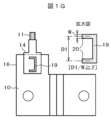
- FIG. 3 is a schematic diagram showing the shape of overlap welding between a voltage detection terminal and a bus bar according to Example 1.
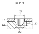
- FIG. 3 is a cross-sectional view showing laser welding in Example 1.
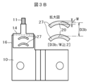
- FIG. 3 is a schematic diagram showing another form of Example 1.
- FIG. 3 is a schematic diagram showing still another form of Example 1.
- FIG. 3 is a schematic diagram showing still another form of Example 1.
- FIG. 3 is a schematic diagram showing still another form of Example 1.
- FIG. 3 is a schematic diagram showing still another form of Example 1.
- FIG. 3 is a schematic diagram showing still another form of Example 1.
- FIG. 3 is a schematic diagram showing the shape of overlap welding between a voltage detection terminal and a bus bar according to a second embodiment.
- FIG. 3 is a cross-sectional view showing laser welding in Example 2.
- FIG. 3 is a schematic diagram showing the shape of overlap welding between a voltage detection terminal and a bus bar according to Example 1.
- FIG. 7 is a schematic diagram showing the shape of overlap welding between a voltage detection terminal and a bus bar according to Example 3;
- FIG. 7 is a schematic diagram illustrating the shape of overlap welding between a voltage detection terminal and a bus bar according to another embodiment of the third embodiment.
- FIG. 3 is a cross-sectional view showing laser welding in Example 3.
- FIG. 7 is a schematic diagram showing the shape of overlap welding between a voltage detection terminal and a bus bar according to Example 4.
- FIG. 7 is a schematic diagram illustrating the shape of overlap welding between a voltage detection terminal and a bus bar according to another embodiment of the fourth embodiment.
- FIG. 4 is a cross-sectional view showing laser welding in Example 4.
- FIG. 7 is a schematic diagram showing the shape of overlap welding between a voltage detection terminal and a bus bar according to Example 5.
- FIG. 5 is a schematic diagram showing the shape of overlap welding between a voltage detection terminal and a bus bar according to Example 5.
- FIG. 7 is a schematic diagram showing the shape of overlap welding between a voltage detection terminal and a bus bar according to another embodiment of Example 5; 5 is a cross-sectional view showing laser welding in Example 5.
- FIG. 7 is a schematic diagram showing the shape of overlap welding between a voltage detection terminal and a bus bar according to Example 6.
- FIG. 6 is a cross-sectional view showing laser welding in Example 6.
- FIG. 7 is a schematic diagram showing the shape of overlap welding between a voltage detection terminal and a bus bar according to Example 7.
- FIG. 7 is a cross-sectional view showing laser welding in Example 7.
- FIG. 7 is a schematic diagram showing the shape of overlap welding between a voltage detection terminal and a bus bar according to Example 8.
- FIG. 8 is a cross-sectional view showing laser welding in Example 8.
- FIG. 8 is a cross-sectional view showing laser welding in Example 8.
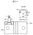
- FIG. 9 is a schematic diagram showing the shape of overlap welding between a voltage detection terminal and a bus bar according to Example 9.
- FIG. 9 is a cross-sectional view showing laser welding in Example 9.
- FIG. 7 is a schematic diagram showing the shape of overlap welding between a voltage detection terminal and a bus bar according to Example 10.
- FIG. 10A is a cross-sectional view along the longitudinal direction of the bus bar in FIG. 10A.
- FIG. 10B is a side view of the bus bar in FIG. 10A taken along the short direction.
- FIG. 7 is a schematic diagram showing the shape of overlap welding between a voltage detection terminal and a bus bar according to another embodiment of Example 10.
- FIG. 10D is a side view taken along the short direction of the bus bar in FIG. 10D.
- FIG. 10A is a cross-sectional view along the longitudinal direction of the bus bar in FIG. 10A.
- FIG. 10B is a side view of the bus bar in FIG. 10A taken along the short direction.
- FIG. 7 is
- FIG. 3 is a cross-sectional view of the bus bar and the voltage detection terminal connected by laser when viewed from the short direction of the bus bar when the bus bar is turned over.
- FIG. 3 is a cross-sectional view of the bus bar and the voltage detection terminal connected by laser when viewed from the longitudinal direction of the bus bar when the bus bar is turned over;
- FIG. 7 is a schematic diagram showing the shape of overlap welding between a voltage detection terminal and a bus bar according to Example 11.
- FIG. 7 is a cross-sectional view showing laser welding in Example 11.
- FIG. 7 is a side view of the relationship between a cell, a bus bar, and a voltage detection terminal in Example 11, viewed from the longitudinal direction of the cell.
- FIG. 3 is a side view of the relationship between a unit cell, a bus bar, and a voltage detection terminal in Examples 1 to 10, viewed from the longitudinal direction of the unit cell.
- FIG. 3 is a side view of the relationship between a unit cell, a bus bar, and a voltage detection terminal in Examples 1 to 10, viewed from the short direction of the unit cell.
- FIG. 2 is a schematic diagram showing the basic structural arrangement and welding of a unit cell, a bus bar, and a voltage detection terminal in a vehicle-mounted assembled battery according to the present invention.
- FIG. 3 is a side view of the relationship between a unit cell, a bus bar, and a voltage detection terminal in Examples 1 to 10, viewed from the short direction of the unit cell.
- FIG. 3 is a side view of the relationship between a unit cell, a bus bar, and a voltage detection terminal in Examples 1 to 10, viewed from the longitudinal direction of the unit cell.
- FIG. 1 is a schematic diagram showing a vehicle-mounted battery assembly according to the present invention.
- FIG. 3 is a plan view showing the relationship among a harness assembly containing a voltage detection line, a voltage detection terminal, and a bus bar in the vehicle-mounted battery assembly according to the present invention.
- FIG. 13 shows an assembled battery 1 using the welded terminal structure according to the present invention.
- the assembled battery 1 has a structure in which a plurality of unit cells 2 are fixed by a pair of end plates 4 and a pair of side plates 5.
- the cell 2 is, for example, a prismatic secondary battery such as a lithium ion secondary battery.
- the rectangular unit cell 2 has a rectangular parallelepiped shape with an upper surface, a lower surface, a pair of plane surfaces with a large area, and a pair of side surfaces with a small area.
- the cells 2 are arranged in a line with their large-area planes facing each other, and holders 3 are provided between each cell 2, in front of the cell 2 at the head of the line, and behind the cell 2 at the end of the line. is interposed.
- the unit cell 2 has a positive electrode 2a and a negative electrode 2b on the upper side, and all have the same size, shape, and structure. Adjacent unit cells 2 are arranged with the positive electrode 2a and the negative electrode 2b facing each other, in other words, the front and back planes are alternately reversed.
- the positive electrode 2a is made of, for example, an aluminum metal such as aluminum or an aluminum alloy
- the negative electrode 2b is made of a copper metal such as copper or a copper alloy.
- End plates 4 are arranged in front of the holder 3 at the beginning of the row and behind the holder 3 at the end of the row.
- the pair of end plates 4 are made of a metal material, have a substantially rectangular shape, and have openings 4a at four corners through which the bolts 6 are inserted.
- a pair of side plates 5 are arranged on the sides of the unit cells 2 arranged in a row.
- Each side plate 5 is a rectangular frame body having a vertically spaced spanning portion and a connecting portion that connects the spanning portion.
- An opening 5a is formed at each corner of the frame in correspondence with the opening 4a of the end plate 4.
- the end plate 4 on the front side of the row and the end plate 4 on the rear side of the row are arranged inside the front and rear connecting parts of each side plate 5, and the bolts 6 are inserted into the opening 5a of the side plate 5 and the end plate 4. It is formed by being inserted into the opening 4a of the plate 4 and fixed by fastening.
- the bolt 6 is fastened by being screwed into a screw hole (not shown) formed in the holder 3, or by placing a nut (not shown) on the back side of the end plate 4. Instead of fastening with bolts 6, it may be fixed with rivets.
- An insulating cover 7 is arranged on the upper side of each unit cell 2 so as to surround the positive and negative electrodes 2a and 2b of the unit cells 2 arranged in a row.
- the positive electrode 2 a and the negative electrode 2 b of adjacent unit cells 2 are connected by a bus bar 10 . All the cells 2 are connected in series by a bus bar 10.
- a bus bar 8 is connected to the positive electrode 2a1 of the cell 2 at the head of the row and the negative electrode 2b1 of the cell 2 at the end of the row.
- the bus bar 10 or the bus bar 8 and the positive and negative electrodes 2a and 2b are joined by welding such as laser welding or ultrasonic welding. It is also possible to have a structure in which the connection is made by screw fastening instead of by welding.
- FIG. 14 is a plan view showing a harness assembly 100 having a voltage detection wiring group 101, a voltage detection terminal 14 connected to the voltage detection wiring group 101, and bus bars 8 and 10 connected to the voltage detection terminal 14.
- the voltage detection wiring group 101 is connected to the outside via a socket 102. Further, voltage measurement wiring is arranged within the branch harness 110 and connected to the voltage detection terminal 14.
- the bus bar 8 is an end bus bar and connects only to the outermost cell, whereas the bus bar 10 connects between the terminals of the two cells 2. Note that the bus bars 8 and 10 shown in FIG. 14 have the simplest configuration and do not have a length structure as shown in the following embodiments.
- FIG. 14 shows a configuration corresponding to 12 single cells 2, corresponding to FIG. 13. Note that in FIG.
- the voltage detection terminal 14 will be described as an example of the first metal member, and the bus bars 8 and 10 (or the part 16 to be welded thereon) will be used as an example of the second metal terminal.
- the first metal member may be a bus bar that connects the battery and an external terminal instead of a bus bar that connects the battery terminals. Applicable to locations with harsh usage environments such as rising temperatures.
- the second metal member may not be the voltage detection terminal but may be another terminal. For example, it can be applied to a temperature detection terminal, etc.
- the "metal welded structure" of the present invention refers to a product that includes these first metal members and second metal members.
- each bus bar 10 is directly connected to the positive electrode 2a and negative electrode 2b of the unit cell 2, so that the terminal voltage of the assembled battery 1 is directly transmitted to the voltage detection terminal 14.
- the weld bead 19 indicating the laser welded part is shown as U-shaped. The reliability of this laser welding at the weld bead 19 is extremely important for the reliability of the entire assembled battery. The content of the present invention will be explained in detail using the following examples.
- FIG. 12A is a schematic diagram of the unit cell 2, the bus bar negative electrode side 10b, and the voltage detection terminal 14 as an assembled battery, as seen from the side surface in the longitudinal direction of the unit cell 2.
- the unit cell 2 is equipped with a positive electrode 2a and a negative electrode 2b, and a bus bar 10 is connected to the top of each terminal to conduct electricity between the terminals of the adjacent unit cell 2.
- the voltage detection line 11 is connected to a voltage detection terminal 14, and the voltage detection terminal 14 is disposed on the surface of the welding target part 16 with a terminal provided so as to protrude toward the negative electrode side of the bus bar 10. and welded.
- the direction of the voltage detection line 11 in FIG. 12A is different from FIGS. 13 and 14, and is oriented outward with respect to the unit cell 2.
- FIG. 12A is simply for explaining the laminated relationship between the bus bar 10 and the voltage detection terminal 14 in the laser bonded portion, and is not in the same direction as the actual product as shown in FIGS. 13 and 14. do not have.
- FIG. 12B is a schematic diagram of the unit cells 2, the bus bar positive electrode sides 10a and 10b, and the voltage detection terminal 14, as seen from the side surface in the short direction of the adjacent unit cells 2 as the assembled battery 1.
- the bus bar positive electrode side 10a and the bus bar negative electrode side 10b are arranged so as to connect the negative electrode 2b and the positive electrode 2a of each adjacent unit cell 2, and are connected to each terminal.
- the voltage detection terminal 14 is disposed on the surface of the welding target portion 16 with a protruding terminal on the bus bar negative electrode side 10b, and welded with the structure of the present invention.
- the upper surface of the bus bar negative electrode side 10b when mounted on the assembled battery 1 will be referred to as the front side, and the lower side will be referred to as the back side.
- FIG. 12C shows the arrangement of members before welding between the voltage detection terminal 14 and the bus bar negative electrode side 10b.
- the voltage detection terminal 14 is arranged above a part 16 to be welded to the voltage detection terminal 14, which is provided so as to protrude from the negative electrode side 10b of the bus bar.
- FIGS. 12D and 12E are side views during welding, FIG. 12D is a side view of the short side of the bus bar, and FIG. 12E is a side view of the long bus bar.
- the surface of the voltage detection terminal 14 arranged as described above is irradiated with laser light, and is welded as a lap joint with the welding target portion 16 on the busbar negative electrode side 10b.
- a laser beam not only a laser beam but also an arc or an electron beam can be used as a method of applying energy for welding.
- a welding method using a laser will be described below.
- the material of the voltage detection terminal 14 is phosphor bronze.
- the corresponding surface 15 of the part 16 to be welded protruding from the bus bar 10 may be plated with Ni or Sn, or may not be plated.
- the material of the bus bar 10 is oxygen-free copper or It is a pure copper type copper material such as phosphorus deoxidized copper or tough pitch copper, or a phosphor bronze copper material.
- the bus bar positive electrode side 10a connected to the positive electrodes 2a to 2a1 of the unit cell 2 is made of an aluminum-based material.
- the copper material part and the aluminum material part are formed as a current-carrying structure by joining, pasting, or fastening.
- FIG. 1A shows a welded structure formed according to the present invention in which the weld bead shape on the surface is U-shaped, as seen from the upper side, which is the voltage detection terminal 14 side.
- the busbar negative electrode side 10b is formed such that a part 16 to be welded with the voltage detection terminal 14 protrudes toward the voltage detection line 11 side, and has a structure in which the voltage detection terminal 14 is overlapped with the part 16 to be welded and welded. .
- the voltage detection terminal 14 is arranged as an upper member, and the welding target portion 16 of the bus bar is arranged as a lower member so that the surface 15 is on top.
- the surface of the voltage detection terminal 14 is irradiated with a continuous beam-shaped laser beam 17 having the characteristics described above to melt and penetrate the voltage detection terminal 14 to form a molten portion from the surface 15 of the welding target portion 16 of the bus bar to a predetermined depth.
- the second linear portion is the facing portion 20.
- the first linear portion is a portion located between the facing portions 20 on both sides.
- the welding bead 19 has the bead of the facing portion 20 located on both sides in the longitudinal direction where the linear bead is formed.
- the bead width of the directly facing portion 20 is The distance D1 between W and the bead center forms a bead shape on the surface of the weld where D1/W ⁇ 2. If there is variation in the bead width W of the facing portion 20, an average value may be taken. The same applies to other embodiments.
- the width D1 of the two ends of the welded part in this example, the distance between the bead centers was used, but the distance between one side of the second linear part in the longitudinal direction of the first linear part was used. It is also possible to use If there is little variation in the bead width W, measurement becomes easy. Note that the laser is irradiated in the thickness direction of the member.
- the welding speed (beam scanning speed) in the case of continuous beam construction is within the range of 50 to 300 mm/s.
- a construction method that sprays either an inert gas or nitrogen as an assist gas, or air or oxygen as a surface activating gas toward the work area. It is also possible to perform construction without the above-mentioned gas blowing.
- the surface width 21 of the weld bead 19 is 0.4 mm or more, and
- the welded structure has a welding width 22 of 0.1 mm or more at the interface shown in FIG.
- the melting depth 23 on the busbar side may be in the range of a melting shape that is 0.1 mm or more and 80% or less of the busbar board thickness.
- the weld bead shape of this embodiment is described as U-shaped, but the shape is not only a linear bent weld bead 19 as shown in FIG. 1A, but also a weld bead 19 as shown in FIG. 1C. It is a welded structure that has the same meaning as a bent shape 24 that is a combination of a straight line and an R curve, or a shape 25 that is a combination of a curved line and a straight line portion as shown in FIG. 1D.
- FIG. 1E shows the results of experimentally verifying the ratio of the bead width W at the facing portion to the distance D1 between the bead centers and the probability of cracking in the weld under the above welding conditions and bead shape. From the same figure, for weld beads that are adjacent to each other with a small distance relative to the bead width, the tensile stress generated during cooling is caused by the first bead that has already been welded when the second adjacent bead is formed during welding. There is a risk that the relaxation of When the second bead is in a high-temperature brittle state, if the tensile stress is applied in a concentrated manner without being relaxed, cracks are likely to occur.
- This shape of the weld bead prevents stress relaxation in the high temperature range during the latter half of construction of adjacent or facing beads, which is a cause of weld cracking in phosphor bronze members, and prevents cracks from occurring. It is possible to avoid concentration of tensile stress and create a welded structure with excellent strength and reliability without cracking.
- the welding bead is oriented so that the facing part 20 faces in the direction in which the terminal of the cell 2 is located, but in the present invention, the jig arrangement, the direction of irradiation of the laser beam 17, etc.
- the facing part 20 may be in an upside-down shape as shown in FIG. It is also possible to have a shape facing to the right. This also applies to the bead shapes shown in FIGS. 1C and 1D.
- FIG. 2A a welding structure in which the weld beads have two L-shapes mirror-symmetrically arranged is shown in FIG. 2.
- the shape of the weld bead is two L-shaped weld beads arranged in mirror symmetry.
- the bead width W of the directly facing portion 20 and the distance D2 between the bead centers form a bead shape on the surface of the welded portion in a relationship of D2/W ⁇ 2.
- the weld bead is described as having mirror symmetry, but it may not be completely mirror symmetrical, but may be substantially mirror symmetrical, such as mirror symmetry as a whole.
- the shape at the center of the bead width is composed of two L-shapes. In this case, the vertical and horizontal lines of L or the area where the vertical and horizontal lines intersect may have curvature.
- this is a welded structure in which the surface width 21 of the weld bead is 0.4 mm or more, and the weld width 22 at the interface shown in the same figure is 0.1 mm or more.
- the specifications of the laser, welding conditions, working atmosphere, depth of the weld, and orientation of the bead are the same as those described in Example 1.
- the relaxation of tensile stress during welding is more effective, and the high temperature region during the latter half of construction of adjacent or facing beads, which was a cause of weld cracking in phosphor bronze members. It is possible to avoid the concentration of tensile stress that inhibits stress relaxation and causes cracks, and to create a welded structure with excellent strength and reliability that does not cause cracks.
- FIG. 3A a welding structure in which the shape of the weld bead is a straight line or a curved line arranged in parallel will be shown using FIG.
- the bead width W of the facing portion 20 and the distance D3a between the bead centers have a relationship of D3a/W ⁇ 2.
- Form a bead shape on the surface of the weld is described as being in parallel, but it is also possible to have substantially parallel forms in which the weld beads are lined up with an interval as a whole.
- the linear shape from one end to the other end as seen from the center of the bead width is arranged with a gap from other beads.
- the distance between one end and the other end is substantially constant.
- this linear shape may be a straight line or an arc shape.
- the bead width W of the facing portion 20 and the distance D3b between the bead centers are D3b/W ⁇ 2.
- the welded structure has a surface width 21 of the weld bead of 0.4 mm or more, and a weld width 22 at the interface shown in the same figure of 0.1 mm or more. .
- the laser specifications, welding conditions, construction atmosphere, weld depth, and bead orientation are the same as those described in Example 1.
- the concentration of tensile stress during welding is alleviated by providing the above-mentioned shape characteristics. Therefore, it is possible to avoid the concentration of tensile stress that inhibits stress relaxation in the high temperature range during the latter half of construction of adjacent or facing beads, which is a cause of weld cracking in phosphor bronze parts, and causes cracks. It is possible to create a welded structure with excellent strength and reliability that does not occur.
- FIG. 4A a welding structure in which the shape of the weld bead is circular or elliptical will be shown using FIG. 4.
- the bead width W and the diameter D4a of the circle between the bead centers form a bead shape on the surface of the weld where D4a/W ⁇ 2.
- the bead width W and the diameter D4b between the bead centers on the shorter side of the ellipse are in the relationship of D4b/W ⁇ 2.
- Form a bead shape in either shape, as shown in FIG. 4C, the welded structure is such that the surface width 21 of the weld bead is 0.4 mm or more, and the weld width 22 at the interface shown in the figure is 0.1 mm or more. .
- the laser specifications, welding conditions, construction atmosphere, weld depth, and bead orientation are the same as those described in Example 1.
- the concentration of tensile stress during welding is alleviated by having the above-mentioned shape characteristics. Therefore, it is possible to avoid the concentration of tensile stress that inhibits stress relaxation in the high temperature range during the latter half of construction of adjacent or facing beads, which is a cause of weld cracking in phosphor bronze parts, and causes cracks. It is possible to create a welded structure with excellent strength and reliability that does not occur.
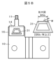
- FIG. 5A a welding structure in which the shape of the weld bead is rectangular will be shown using FIG. 5.
- the bead width W at the facing portion and the distance D5a between the bead centers form a bead shape on the surface of the weld where D5a/W ⁇ 2.
- a bead shape is formed in which the welding area having a distance of D5a is not a straight line but a curved line.
- the bead width W of the facing portion and the distance D5b between the bead centers are welded in a relationship of D5b/W ⁇ 2.
- the welded structure has a surface width 21 of the weld bead of 0.4 mm or more, and a weld width 22 at the interface shown in the same figure of 0.1 mm or more.
- the specifications of the laser, welding conditions, working atmosphere, depth of the weld, and orientation of the bead are the same as those described in Example 1.
- the concentration of tensile stress during welding is alleviated. Therefore, it is possible to avoid the concentration of tensile stress that inhibits stress relaxation in the high temperature range during the latter half of construction of adjacent or facing beads, which is a cause of weld cracking in phosphor bronze parts, and causes cracks. It is possible to create a welded structure with excellent strength and reliability that does not occur.
- FIG. 6A is a diagram of a welded portion 32 formed in the form of two spots according to the present invention, viewed from the upper side, which is the voltage detection line side.
- a weld bead shape is formed in which the distance D6 between the W of adjacent weld beads 32 and the spot center satisfies the relationship D6/W ⁇ 2.
- the number of spot welds is not limited to two, but may be more as long as the above relationship is satisfied.
- a dot shape is described as a welding spot as the form of the weld bead, and the width D6 between the two points of the welded part is the distance between the centers of the spots in this example, but in the direction connecting the spots. In this case, it is also possible to use the distance between the ends of one side. Measurement becomes easier when there is little variation in the size of welding spots.
- the form of the laser irradiated at this time can be either a pulsed laser or a continuous beam, and the spot diameter of the laser beam is 0.04 to 0.6 mm in diameter.
- a spot-like welding beam shape can be formed by scanning a minute beam with swinging of the beam.
- the working atmosphere including assist gas and the like is the same as in Example 1.
- the surface width 21 of the welded part is 0.4 mm or more, and the weld width 22 at the interface shown in the same figure is 0.1 mm or more. It is a welded structure with a large size.
- FIG. 7A is a diagram of a weld bead formed according to the present invention of a part to be welded 34 provided in a shape protruding from a bus bar 33 which is an integral part made of an aluminum-based material, as seen from the upper side, which is the voltage detection line side.
- FIG. 7B is a cross-sectional view of the welded portion.
- the welded part is not only susceptible to cracking due to the high-temperature embrittlement of the phosphor bronze member, but also has increased susceptibility to cracking due to the embrittlement of the copper-aluminum compound. do.
- the weld bead 35 has a U-shape with a bent portion and has bead portions directly facing each other.
- the bead width W of the paired portion 20 and the distance D7 between the bead centers form a bead shape on the surface of the welded portion having a relationship of D7/W ⁇ 2.
- the weld bead shape includes not only the shape of the weld bead 35 but also the shapes described in Examples 1 to 6. Regardless of the bead shape, as shown in FIG. 7B, the welded structure has a surface width 21 of the weld bead of 0.4 mm or more, and a weld width 22 at the interface shown in the same figure of 0.1 mm or more. .
- the specifications of the laser and the specifications regarding welding conditions are also the same as in Examples 1 to 6.
- the fusion depth 36 on the bus bar side of the welding target part 34 made of aluminum is 0.1 mm or more, and the upper limit is the thickness T of the voltage detection terminal 14 regardless of the bus bar thickness.
- FIG. 8A a part 37 to be welded with the voltage detection terminal of the bus bar is provided as a flat part at the outer end of the negative electrode side 10b of the bus bar in the direction adjacent to the cell battery, and a voltage detection terminal 38 having a shape that matches the shape of the flat part is overlapped.
- a shape 39 in which the weld bead is U-shaped with a curved portion and has bead portions directly facing each other the bead width W of the directly facing portion 20 and the distance D8 between the bead centers are as follows.
- a bead shape is formed on the surface of the welded part in the relationship of D8/W ⁇ 2.
- the weld bead shape includes not only shape 39 but also each shape for each material described in Examples 1 to 7. Regardless of the shape, as shown in FIG. 8B, the welded structure has a surface width 21 of the weld bead of 0.4 mm or more, and a weld width 22 at the interface shown in the figure of 0.1 mm or more.
- the laser specifications, welding conditions, working atmosphere, depth of the weld, bead direction, or spot shape are the same as those described in Examples 1 to 7 above.
- This welded structure creates a margin in the area between the bus bar of the assembled battery and the wire bundle terminal of the voltage detection line, making it possible to achieve a smaller or higher density mounting structure for the assembled battery.
- FIG. 9A discloses a second configuration that shows a change in the position of the joint.
- a voltage detection terminal 40 having a predetermined shape is stacked near the outer diameter end of the construction part to be connected to the terminal of the unit cell 2 on the bus bar negative electrode side 10b without providing a protruding flat part on the bus bar negative electrode side 10b.
- the bead width W of the facing portion 20 and the bead center are The distance D9 forms a bead shape on the surface of the weld where D9/W ⁇ 2.
- this is a welded structure in which the surface width 21 of the weld bead is 0.4 mm or more, and the weld width 22 at the interface shown in the figure is 0.1 mm or more.
- the weld bead shape includes not only the shape 41 but also the shapes for each material described in Examples 1 to 7.
- This welded structure creates a margin in the area between the bus bars 8 and 10 of the battery pack 1 and the wire bundle terminal of the voltage detection line 11, and at the same time allows the bus bar 10 to be made smaller, making it possible to make the battery pack 1 smaller or more dense. It is possible to have the following implementation structure.
- FIG. 10A a further example of a change in the shape of the welded part to the bus bar will be shown using FIG. 10.
- the part 42 to be welded to the voltage detection terminal of the bus bar is provided protruding from the outer diameter end of the adjacent cell and is simultaneously bent upward, while the voltage detection terminal 43 is U-shaped or square shaped.
- FIG. 10B is a cross-sectional view of the fitting portion between the welding target portion 42 of the bus bar and the voltage detection terminal 43.
- FIG. 10C is a view of the fitting portion between the welding target portion 42 and the voltage detection terminal 43 and the surface of the welded portion as seen from the side surface on the short side closer to the center of the bus bar negative electrode side 10b.
- the weld bead 45 which has a U-shape with a curved portion and has bead portions facing each other, which is the shape of the weld bead of the present invention, the bead width W of the facing portion and the distance D10a between the bead centers are , D10a/W ⁇ 2.
- the welded structure has a surface width 21 of the weld bead 45 of 0.4 mm or more, and a weld width 22 at the interface shown in the same figure of 0.1 mm or more.
- the weld bead shape includes not only the weld bead 45 but also the shapes of each material described in Examples 1 to 7.
- the laser specifications, welding conditions, working atmosphere, depth of the weld, bead direction, or spot shape are the same as those described in Examples 1 to 7 above.
- this shape also provides the strength effect of fitting and fixing, so as shown in FIG.
- This welding bead 46 is not limited to being formed on the side surface of the bent portion shown in FIG. 10E, but may also be formed on the top surface of the fitting portion.
- FIG. 11 shows that the bus bar 10 is arranged so that the back surface 47, which is defined above as the top and bottom surfaces of the bus bar when attached to the assembled battery 1, is on the top side during welding, and the voltage detection terminal is placed on the top of the bus bar 10. 14 is arranged and the surface of the voltage detection terminal is irradiated with a laser beam 17 to weld.
- FIG. 11A is a view seen from the side surface of the short side of the bus bar
- FIG. 11B is a view seen from the side surface of the long side of the bus bar.
- FIG. 11C is a top view of the laser irradiated side.
- the weld bead As shown in the figure, in the shape 48 of the weld bead, which is the shape of the weld bead of the present invention, the weld bead has a U-shape with a bent part and has bead parts facing directly.
- the bead width W and the distance D11 between the bead centers form a bead shape on the surface of the weld where D11/W ⁇ 2.
- the welded structure has a surface width 21 of the weld bead of 0.4 mm or more, and a weld width 22 at the interface shown in the same figure of 0.1 mm or more.
- the structure of the welded joint or the shape of the weld bead includes not only the shape 48 but also each joint structure and welded shape of each material described in Examples 1 to 10.
- the laser specifications, welding conditions, working atmosphere, depth of the weld, bead orientation, and spot shape are the same as those described in Examples 1 to 7 above.
- FIG. 11E shows a structure in which the bus bar negative electrode side 10b and voltage detection terminal 14 welded in the above manner are mounted as a battery pack 1. When mounted as the assembled battery 1, the voltage detection terminal 14 is welded to the lower side of the bus bar negative electrode sides 10b and 16.
- FIG. 11E shows a structure in which the bus bar negative electrode side 10b and voltage detection terminal 14 welded in the above manner are mounted as a battery pack 1. When mounted as the assembled battery 1, the voltage detection terminal 14 is welded to the lower side of the bus bar negative electrode sides 10b and 16.
- FIG. 11E shows a structure in which the bus bar negative electrode side 10b and voltage detection terminal 14 welded in the above manner are mounted as
- the part 16 to be welded on the bus bar negative electrode side 10b protrudes to the outside of the cell 2, but this is a diagram for explaining Example 11, and in the actual product, the part 16 to be welded is
- the target portion 16 and the voltage detection terminal 14 face toward the inside of the cell 2, as shown in FIGS. 13 and 14.
- the welded structure shown in this example it is possible to obtain a welded structure with excellent adhesion to the voltage detection terminal and excellent welding quality when the back surface of the bus bar 10 has a higher flatness. be. Furthermore, as for the assembled state of the parts in the actual machine construction, there is not only a construction method in which the bus bar 10 is placed alone and welded to the voltage detection terminal, but also a construction method in which the bus bar 10 is placed alone and welded to the voltage detection terminal, but also in a resin bus bar case in which the voltage detection wire bundle and the bus bar are mounted on the top of the assembled battery.
- the height of the resin part on the back side of the case is set to a shape that does not interfere with the jig, so that it is possible to achieve a construction method that has the effect of reducing the effect of heat on the resin part during laser welding.
Landscapes
- Chemical & Material Sciences (AREA)
- Chemical Kinetics & Catalysis (AREA)
- Electrochemistry (AREA)
- General Chemical & Material Sciences (AREA)
- Engineering & Computer Science (AREA)
- Optics & Photonics (AREA)
- Physics & Mathematics (AREA)
- Mechanical Engineering (AREA)
- Plasma & Fusion (AREA)
- Inorganic Chemistry (AREA)
- Manufacturing & Machinery (AREA)
- Laser Beam Processing (AREA)
- Connection Of Batteries Or Terminals (AREA)
Priority Applications (4)
| Application Number | Priority Date | Filing Date | Title |
|---|---|---|---|
| US18/868,857 US20250372827A1 (en) | 2022-06-16 | 2022-12-21 | Metal welded structure, battery pack using same, and battery pack production method |
| JP2024528273A JPWO2023243122A1 (https=) | 2022-06-16 | 2022-12-21 | |
| CN202280095863.4A CN119174048A (zh) | 2022-06-16 | 2022-12-21 | 金属焊接结构体及使用该金属焊接结构体的电池组及电池组的制造方法 |
| EP22946937.4A EP4542759A4 (en) | 2022-06-16 | 2022-12-21 | METAL WELDED STRUCTURE, BATTERY PACK USING SAME, AND BATTERY PACK PRODUCTION METHOD |
Applications Claiming Priority (2)
| Application Number | Priority Date | Filing Date | Title |
|---|---|---|---|
| JP2022-097252 | 2022-06-16 | ||
| JP2022097252 | 2022-06-16 |
Publications (1)
| Publication Number | Publication Date |
|---|---|
| WO2023243122A1 true WO2023243122A1 (ja) | 2023-12-21 |
Family
ID=89192532
Family Applications (1)
| Application Number | Title | Priority Date | Filing Date |
|---|---|---|---|
| PCT/JP2022/047252 Ceased WO2023243122A1 (ja) | 2022-06-16 | 2022-12-21 | 金属溶接構造体及びこれを用いた組電池及び組電池の製造方法 |
Country Status (5)
| Country | Link |
|---|---|
| US (1) | US20250372827A1 (https=) |
| EP (1) | EP4542759A4 (https=) |
| JP (1) | JPWO2023243122A1 (https=) |
| CN (1) | CN119174048A (https=) |
| WO (1) | WO2023243122A1 (https=) |
Cited By (2)
| Publication number | Priority date | Publication date | Assignee | Title |
|---|---|---|---|---|
| WO2025197154A1 (ja) * | 2024-03-19 | 2025-09-25 | ビークルエナジージャパン株式会社 | 異種金属接合構造体、及び組電池 |
| DE102024112278A1 (de) * | 2024-05-02 | 2025-11-06 | Martin Ziegler | Stoffschlüssige elektrotechnische Komponente und Kontaktierungsverfahren für diese |
Citations (7)
| Publication number | Priority date | Publication date | Assignee | Title |
|---|---|---|---|---|
| JPS57170419A (en) * | 1981-04-13 | 1982-10-20 | Matsushita Electric Works Ltd | Contact welding method |
| JP2009233712A (ja) * | 2008-03-27 | 2009-10-15 | Hiroshima Pref Gov | 溶接継手構造および溶接方法 |
| JP5457605B2 (ja) | 2011-05-30 | 2014-04-02 | パナソニック株式会社 | レーザ接合部品およびその製造方法 |
| JP2014087848A (ja) | 2010-09-16 | 2014-05-15 | Nippon Steel & Sumitomo Metal | 成形部材 |
| JP2016173972A (ja) * | 2015-03-18 | 2016-09-29 | パナソニックIpマネジメント株式会社 | 密閉型電池及びその製造方法 |
| JP6176428B1 (ja) | 2016-03-15 | 2017-08-09 | Jfeスチール株式会社 | 重ねレーザ溶接継手、該溶接継手の製造方法および自動車用骨格部品 |
| WO2020194964A1 (ja) * | 2019-03-27 | 2020-10-01 | 三洋電機株式会社 | 電圧検出線および電池モジュール |
Family Cites Families (3)
| Publication number | Priority date | Publication date | Assignee | Title |
|---|---|---|---|---|
| JP2001062575A (ja) * | 1999-08-25 | 2001-03-13 | Nippon Steel Corp | 金属板のレーザ溶接方法および構造体 |
| JP6814389B2 (ja) * | 2017-04-10 | 2021-01-20 | トヨタ自動車株式会社 | 組電池 |
| DE102018209981A1 (de) * | 2018-06-20 | 2019-12-24 | Robert Bosch Gmbh | Verfahren zum Verbinden zweier Bauteile und Bauteileverbund |
-
2022
- 2022-12-21 JP JP2024528273A patent/JPWO2023243122A1/ja active Pending
- 2022-12-21 CN CN202280095863.4A patent/CN119174048A/zh active Pending
- 2022-12-21 EP EP22946937.4A patent/EP4542759A4/en active Pending
- 2022-12-21 US US18/868,857 patent/US20250372827A1/en active Pending
- 2022-12-21 WO PCT/JP2022/047252 patent/WO2023243122A1/ja not_active Ceased
Patent Citations (7)
| Publication number | Priority date | Publication date | Assignee | Title |
|---|---|---|---|---|
| JPS57170419A (en) * | 1981-04-13 | 1982-10-20 | Matsushita Electric Works Ltd | Contact welding method |
| JP2009233712A (ja) * | 2008-03-27 | 2009-10-15 | Hiroshima Pref Gov | 溶接継手構造および溶接方法 |
| JP2014087848A (ja) | 2010-09-16 | 2014-05-15 | Nippon Steel & Sumitomo Metal | 成形部材 |
| JP5457605B2 (ja) | 2011-05-30 | 2014-04-02 | パナソニック株式会社 | レーザ接合部品およびその製造方法 |
| JP2016173972A (ja) * | 2015-03-18 | 2016-09-29 | パナソニックIpマネジメント株式会社 | 密閉型電池及びその製造方法 |
| JP6176428B1 (ja) | 2016-03-15 | 2017-08-09 | Jfeスチール株式会社 | 重ねレーザ溶接継手、該溶接継手の製造方法および自動車用骨格部品 |
| WO2020194964A1 (ja) * | 2019-03-27 | 2020-10-01 | 三洋電機株式会社 | 電圧検出線および電池モジュール |
Non-Patent Citations (1)
| Title |
|---|
| See also references of EP4542759A4 |
Cited By (2)
| Publication number | Priority date | Publication date | Assignee | Title |
|---|---|---|---|---|
| WO2025197154A1 (ja) * | 2024-03-19 | 2025-09-25 | ビークルエナジージャパン株式会社 | 異種金属接合構造体、及び組電池 |
| DE102024112278A1 (de) * | 2024-05-02 | 2025-11-06 | Martin Ziegler | Stoffschlüssige elektrotechnische Komponente und Kontaktierungsverfahren für diese |
Also Published As
| Publication number | Publication date |
|---|---|
| JPWO2023243122A1 (https=) | 2023-12-21 |
| EP4542759A4 (en) | 2025-10-08 |
| EP4542759A1 (en) | 2025-04-23 |
| US20250372827A1 (en) | 2025-12-04 |
| CN119174048A (zh) | 2024-12-20 |
Similar Documents
| Publication | Publication Date | Title |
|---|---|---|
| JP5601203B2 (ja) | 端子間接続導体、組電池、及び組電池の製造方法 | |
| KR100842493B1 (ko) | 이금속 박판의 용접 방법, 이금속 박판 접합체, 전기디바이스 및 전기 디바이스 집합체 | |
| EP3351339B1 (en) | Weld structure of metal member and welding process | |
| KR101554361B1 (ko) | 이종 금속 용접 방법, 이에 의해 제조된 이종 금속 버스 바 및 이를 포함하는 이차전지 | |
| WO2023243122A1 (ja) | 金属溶接構造体及びこれを用いた組電池及び組電池の製造方法 | |
| US20220355406A1 (en) | Laser welding method, welding structure, and bus bar module | |
| KR20130049984A (ko) | 배터리를 위한 버스바 및 이를 이용한 배터리 모듈 | |
| JP5957651B2 (ja) | 組電池 | |
| KR102889250B1 (ko) | 버스 바 및 그것을 구비한 조전지 | |
| US10714714B2 (en) | Electrical energy store, specifically a battery cell, with spatially-optimized electrode interconnection | |
| US12451565B2 (en) | Battery assembly and method of manufacturing the same | |
| JP4586008B2 (ja) | 組電池及びその製造方法 | |
| KR20240130030A (ko) | 축전 디바이스 및 이를 구비한 축전 모듈 | |
| JP2009087707A (ja) | セル端子構造、セル端子間接続構造およびセル端子製造方法。 | |
| EP4439850A2 (en) | Battery cell assembly having structure that minimizes difference in thermal characteristics of welded portion | |
| JP4637122B2 (ja) | 組電池及びその溶接方法 | |
| US20260027654A1 (en) | Welding method and welding structure | |
| JP2026070659A (ja) | 電池ケース、電池、及び電池ケースの製造方法 | |
| WO2025142710A1 (ja) | 金属構造体、筐体、電池モジュール及び電池パック | |
| JP2026070660A (ja) | 電池ケース、電池、及び電池ケースの製造方法 | |
| CN119944243A (zh) | 电池模块及其制造方法 | |
| JP2024168866A (ja) | レーザ溶接用クラッド材、レーザ溶接用クラッド材を用いた接合構造、および電池の製造方法 |
Legal Events
| Date | Code | Title | Description |
|---|---|---|---|
| 121 | Ep: the epo has been informed by wipo that ep was designated in this application |
Ref document number: 22946937 Country of ref document: EP Kind code of ref document: A1 |
|
| WWE | Wipo information: entry into national phase |
Ref document number: 2024528273 Country of ref document: JP |
|
| WWE | Wipo information: entry into national phase |
Ref document number: 18868857 Country of ref document: US |
|
| WWE | Wipo information: entry into national phase |
Ref document number: 2022946937 Country of ref document: EP |
|
| NENP | Non-entry into the national phase |
Ref country code: DE |
|
| ENP | Entry into the national phase |
Ref document number: 2022946937 Country of ref document: EP Effective date: 20250116 |
|
| WWP | Wipo information: published in national office |
Ref document number: 2022946937 Country of ref document: EP |
|
| WWP | Wipo information: published in national office |
Ref document number: 18868857 Country of ref document: US |