WO2023242966A1 - ブレーキ制御装置 - Google Patents
ブレーキ制御装置 Download PDFInfo
- Publication number
- WO2023242966A1 WO2023242966A1 PCT/JP2022/023861 JP2022023861W WO2023242966A1 WO 2023242966 A1 WO2023242966 A1 WO 2023242966A1 JP 2022023861 W JP2022023861 W JP 2022023861W WO 2023242966 A1 WO2023242966 A1 WO 2023242966A1
- Authority
- WO
- WIPO (PCT)
- Prior art keywords
- brake
- power supply
- power
- command line
- line
- Prior art date
- Legal status (The legal status is an assumption and is not a legal conclusion. Google has not performed a legal analysis and makes no representation as to the accuracy of the status listed.)
- Ceased
Links
Images








Classifications
-
- B—PERFORMING OPERATIONS; TRANSPORTING
- B60—VEHICLES IN GENERAL
- B60T—VEHICLE BRAKE CONTROL SYSTEMS OR PARTS THEREOF; BRAKE CONTROL SYSTEMS OR PARTS THEREOF, IN GENERAL; ARRANGEMENT OF BRAKING ELEMENTS ON VEHICLES IN GENERAL; PORTABLE DEVICES FOR PREVENTING UNWANTED MOVEMENT OF VEHICLES; VEHICLE MODIFICATIONS TO FACILITATE COOLING OF BRAKES
- B60T17/00—Component parts, details, or accessories of power brake systems not covered by groups B60T8/00, B60T13/00 or B60T15/00, or presenting other characteristic features
- B60T17/18—Safety devices; Monitoring
- B60T17/22—Devices for monitoring or checking brake systems; Signal devices
- B60T17/228—Devices for monitoring or checking brake systems; Signal devices for railway vehicles
-
- B—PERFORMING OPERATIONS; TRANSPORTING
- B60—VEHICLES IN GENERAL
- B60T—VEHICLE BRAKE CONTROL SYSTEMS OR PARTS THEREOF; BRAKE CONTROL SYSTEMS OR PARTS THEREOF, IN GENERAL; ARRANGEMENT OF BRAKING ELEMENTS ON VEHICLES IN GENERAL; PORTABLE DEVICES FOR PREVENTING UNWANTED MOVEMENT OF VEHICLES; VEHICLE MODIFICATIONS TO FACILITATE COOLING OF BRAKES
- B60T13/00—Transmitting braking action from initiating means to ultimate brake actuator with power assistance or drive; Brake systems incorporating such transmitting means, e.g. air-pressure brake systems
- B60T13/10—Transmitting braking action from initiating means to ultimate brake actuator with power assistance or drive; Brake systems incorporating such transmitting means, e.g. air-pressure brake systems with fluid assistance, drive, or release
- B60T13/66—Electrical control in fluid-pressure brake systems
- B60T13/665—Electrical control in fluid-pressure brake systems the systems being specially adapted for transferring two or more command signals, e.g. railway systems
-
- B—PERFORMING OPERATIONS; TRANSPORTING
- B60—VEHICLES IN GENERAL
- B60T—VEHICLE BRAKE CONTROL SYSTEMS OR PARTS THEREOF; BRAKE CONTROL SYSTEMS OR PARTS THEREOF, IN GENERAL; ARRANGEMENT OF BRAKING ELEMENTS ON VEHICLES IN GENERAL; PORTABLE DEVICES FOR PREVENTING UNWANTED MOVEMENT OF VEHICLES; VEHICLE MODIFICATIONS TO FACILITATE COOLING OF BRAKES
- B60T2270/00—Further aspects of brake control systems not otherwise provided for
- B60T2270/40—Failsafe aspects of brake control systems
- B60T2270/402—Back-up
Definitions
- the present disclosure relates to a brake control device.
- the brake control device installed on a railway vehicle is either a service brake control that controls the mechanical brake device to generate braking force, or an emergency brake control that controls the mechanical brake device to generate a greater braking force than during service brake control. I do.
- a service brake control that controls the mechanical brake device to generate braking force
- an emergency brake control that controls the mechanical brake device to generate a greater braking force than during service brake control.
- a brake control device that controls a mechanical brake device by supplying air supplied from an air reservoir to the mechanical brake device includes a solenoid valve and a brake control device that controls the solenoid valve.
- the brake control unit includes a brake control unit, and a housing that accommodates the solenoid valve and the brake control unit.
- the brake control unit includes a plurality of boards each corresponding to each brake control function, a backplane to which the plurality of boards are connected, and a subrack that accommodates the plurality of boards and the backplane.
- the emergency brake command line that runs inside the housing branches. The emergency brake command line is connected to each board.
- the brake operation in the main controller may not correspond to the actual brake control.
- the emergency brake command line which is an example of an abnormality
- DC power will not be supplied to the brake control device via the emergency brake command line, so the brake control device will not be able to operate the emergency brake in the master controller.
- Emergency brake control is performed even though the system is not activated. If the branched emergency brake command line is connected to each board, it will take time to identify the location where an abnormality has occurred in the emergency brake command line, so brake operation and actual brake control must correspond as described above. It takes time to resolve the situation.
- the present disclosure has been made in view of the above-mentioned circumstances, and an object of the present disclosure is to provide a brake control device that can shorten the time required to resolve the situation where the brake operation in the master controller does not correspond to the actual brake control. With the goal.
- a brake control device that controls a mechanical brake device mounted on a railway vehicle, and includes a backplane, a power supply board, and a brake control board. Be prepared.
- the backplane has multiple slots.
- a power line and a command line electrically connected to the plurality of slots are formed in the backplane.
- a power supply board is attached to one of the slots.
- the power supply board receives DC power from the control power supply via the control power line, receives DC power from the emergency brake power supply via the emergency brake command line, and supplies DC power to the power line.
- a power supply circuit is formed that applies a DC voltage to the command line in accordance with the voltage value of the DC voltage applied to the emergency brake command line.
- a brake control board is attached to either of the slots.
- the brake control board is formed with a brake control circuit that controls the mechanical brake device according to the brake command of the railway vehicle and the voltage value of the DC voltage applied to the command line.
- the brake control circuit formed on the brake control board controls mechanical brake control according to the brake command and the voltage value of the DC voltage applied to the command line. Therefore, there is no need to branch the emergency command line connected to the power supply board and connect it to the brake control board. As a result, it becomes easy to identify the location where an abnormality has occurred in the emergency brake command line, and the time required to resolve the situation where the brake operation in the master controller does not correspond to the actual brake control can be shortened.
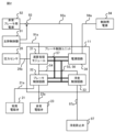
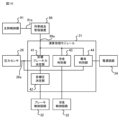
- Block diagram of a brake control device Block diagram of a brake control unit according to Embodiment 1 Block diagram of a brake control unit according to Embodiment 1 Block diagram of arithmetic processing module according to Embodiment 1 Block diagram showing the hardware configuration of the arithmetic processing module according to the first embodiment A block diagram showing a hardware configuration of a brake control circuit according to Embodiment 1.
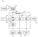
- Exploded perspective view of the brake control unit according to Embodiment 1 A perspective view of a brake control unit according to Embodiment 1 A diagram showing an example of implementation of a power supply circuit according to Embodiment 1 Block diagram of a brake control device according to Embodiment 2 Block diagram of a brake control unit according to Embodiment 2 Block diagram of arithmetic processing module according to Embodiment 2 Exploded perspective view of the brake control unit according to Embodiment 2 A diagram showing an example of implementation of a power supply circuit according to Embodiment 2 A diagram showing an example of implementation of a power supply circuit according to Embodiment 3 A diagram showing an example of implementation of a power supply circuit according to Embodiment 4 Block diagram of a modification of the arithmetic processing module according to the embodiment
- Embodiment 1 A brake control device according to Embodiment 1 will be described using as an example a brake control device that controls a mechanical brake device mounted on a railway vehicle.
- the brake control device 1 shown in FIG. 1 is connected to a master controller 91 via a transmission line 91a, to an emergency brake power source 92 via an emergency brake command line 92a and a contactor 93, and to a control power source 94. It is connected via a control power supply line 94a.
- the brake control device 1 is connected to an air spring 95 and a fluid source 96.
- thick solid lines indicate air pipes, and thin solid lines indicate power lines or signal lines.
- the brake control device 1 receives fluid supply from a fluid source 96, adjusts the pressure of the fluid, and supplies the fluid with the adjusted pressure to a mechanical brake device 98 connected via an anti-skid valve 97. , controls the mechanical brake device 98.
- the brake control device 1 is provided in each vehicle of a railway vehicle.
- the emergency brake power source 92 is a power source common to the plurality of brake control devices 1.
- the air spring 95 is provided for each bogie that supports the body of each vehicle.
- a mechanical brake device 98 is provided for each wheel.
- An anti-skid valve 97 is provided for each mechanical brake device 98.
- the master controller 91 is provided, for example, in the driver's cab, and outputs driving commands to the brake control device 1 in response to operations by the operator.
- the driving command includes any one of a power running command that instructs the acceleration of the railway vehicle, a brake command that instructs the deceleration of the railway vehicle, and a coasting command that instructs the coasting operation of the railway vehicle.
- the coasting command indicates a state in which neither a driving command nor a brake command is included.
- the emergency brake power supply 92 is, for example, a 100V DC power supply, and supplies DC power to the brake control device 1 provided in each vehicle via an emergency brake command line 92a that is connected to all vehicles of the railway vehicle. do.
- the contactor 93 is closed or opened by operation of the main controller 91, a command from an ATS (Automatic Train Stop) device, operation of an emergency switch, or the like. While the contactor 93 is turned on, DC power is supplied from the emergency brake power source 92 to the brake control device 1 .
- the brake control device 1 controls the mechanical brake device 98. performs service brake control to generate braking force.
- the brake control device 1 controls the mechanical brake device 98 to apply an emergency brake to generate a larger braking force than during service brake control. Take control.
- the contactor 93 is turned on or opened in response to a contactor control signal output by the master controller 91 in response to an operation by an operator.
- the contactor 93 is turned on when the railway vehicle starts operating.
- the main controller 91 outputs a driving command to the brake control device 1 and sends a contactor control signal instructing the closing of the contactor 93 to the contactor. Send to 93.
- the contactor 93 remains closed.
- the main controller 91 When the operator performs an operation corresponding to an emergency brake, the main controller 91 outputs an operation command including a brake command to the brake control device 1, and sends a contactor control signal to the contactor 93 instructing the opening of the contactor 93. send to As a result, contactor 93 is opened.
- the brake control device 1 performs emergency brake control that controls the mechanical brake device 98 to generate a greater braking force than during regular brake control.
- the control power supply 94 is a DC power supply, and supplies DC power to the brake control device 1 via the control power supply line 94a.
- the air spring 95 is provided on a bogie that supports the body of a railway vehicle.
- the brake control device 1 is connected to an air chamber of an air spring 95 via an air pipe.
- the fluid source 96 supplies the brake control device 1 with fluid used to operate the mechanical brake device 98.
- air is used as the fluid supplied by the fluid source 96.
- the anti-skid valve 97 is provided in an air pipe connecting the brake control device 1 and the mechanical brake device 98, and is connected to the brake control device 1 via a signal line 97a.
- the anti-skid valve 97 opens under the control of the brake control device 1.
- the air supplied to the mechanical brake device 98 is discharged from the anti-skid valve 97, and the pressure of the air supplied to the mechanical brake device 98 is reduced. This reduces the braking force produced by the mechanical brake system 98 and causes the wheels to re-adhere to the rail.
- the mechanical brake device 98 includes a brake cylinder that receives air supply from the brake control device 1, and a piston that is partially located inside the brake cylinder and slides according to the pressure of the air inside the brake cylinder.
- the mechanical brake device 98 further includes a brake shoe, for example, as a friction material attached to the piston. Braking force is generated when the piston slides in response to the air pressure in the brake cylinder and presses the brake shoe against the rotating wheel.
- the brake control device 1 operates by receiving DC power from the control power supply 94 via the control power supply line 94a, and receives the brake command included in the operation command obtained from the master controller 91 and the emergency brake command line 92a. Depending on the voltage value of the applied DC voltage, service brake control or emergency brake control of the mechanical brake device 98 is performed.
- the brake control device 1 adjusts the pressure of air supplied from the fluid source 96 according to the target deceleration indicated by the brake command and the measured value of the pressure in the air chamber of the air spring 95, and adjusts the pressure of the air supplied from the fluid source 96.
- the regulated air is supplied to a mechanical brake device 98 via an anti-skid valve 97.
- the brake control device 1 adjusts the pressure of the air supplied from the fluid source 96 according to the pressure of the air supplied from the air spring 95, and supplies the adjusted air to the anti-skid valve 97.
- a mechanical brake device 98 is supplied through the brake system.
- the brake control device 1 includes a brake control unit 11 that performs service brake control or emergency brake control, and a service solenoid valve 21 that adjusts the pressure of air supplied from a fluid source 96 in accordance with a signal from the brake control unit 11. Equipped with The brake control device 1 further includes a variable load valve 22 that compresses and outputs the air supplied from the fluid source 96 according to the pressure of the air supplied from the air spring 95, and a variable load valve 22 that compresses and outputs the air supplied from the fluid source 96 according to the pressure of the air supplied from the air spring 95; An emergency solenoid valve 23 that outputs the fluid output from the variable load valve 22 is provided.
- the regular solenoid valve 21 is connected to the brake control unit 11 via a signal line 21a
- the emergency solenoid valve 23 is connected to the brake control unit 11 via a signal line 23a.
- the brake control device 1 further includes a double check valve 24 that outputs high pressure air out of the air output by the regular solenoid valve 21 and the emergency solenoid valve 23, and a double check valve 24 that outputs high pressure air according to the pressure of the air output by the double check valve 24. and a relay valve 25 that adjusts the pressure of the air supplied from the fluid source 96 and supplies the pressure-adjusted air to the mechanical brake device 98 via the anti-skid valve 97.
- the brake control device 1 further includes a pressure sensor 26 that measures the pressure of the air in the air chamber of the air spring 95 and the pressure of the air output from the relay valve 25, respectively.
- the regular solenoid valve 21 is connected to the brake control unit 11 via a signal line 21a.
- the regular solenoid valve 21 adjusts the pressure of air supplied from the fluid source 96 in response to a solenoid valve control signal sent from the brake control unit 11, and sends the pressure-adjusted air to the double check valve 24.
- variable load valve 22 adjusts the pressure of the air supplied from the fluid source 96 by displacing an internal piston according to the pressure of the air supplied from the air spring 95, and distributes the pressure-adjusted air to multiple sources. It is sent to the check valve 24. It is assumed that the pressure of the air outputted by the variable load valve 22 is greater than the maximum value that the pressure of the air outputted by the regular electromagnetic valve 21 can take. This makes it possible to generate a larger braking force during emergency brake control than during regular brake control.
- the double check valve 24 is a solenoid valve with high priority. Specifically, the double check valve 24 outputs high-pressure air out of the air output by the regular solenoid valve 21 and the emergency solenoid valve 23.
- the relay valve 25 adjusts the pressure of the air output from the fluid source 96 according to the pressure of the air output from the double check valve 24, and supplies the adjusted air to the mechanical brake device via the anti-skid valve 97. Supply to 98.
- the pressure sensor 26 is connected to the relay valve 25 and the air spring 95. Pressure sensor 26 is connected to brake control unit 11 via signal line 26a. The pressure sensor 26 sends the measured value of the air pressure output by the relay valve 25 and the measured value of the pressure inside the air chamber of the air spring 95 to the brake control unit 11.
- the brake control unit 11 determines the target pressure, which is the target value of the pressure of the air supplied to the mechanical brake device 98, from the brake command included in the operation command acquired from the master controller 91, It includes an arithmetic processing module 31 that determines whether or not the wheels of the railway vehicle are skidding.
- the brake control unit 11 further includes a brake control circuit 32 that controls the regular solenoid valve 21 or the emergency solenoid valve 23 according to the target pressure and the voltage value of the DC voltage applied to the emergency brake command line 92a, and an arithmetic processing module 31.
- a skid control circuit 33 that controls the skid prevention valve 97 according to the presence or absence of skid determined by the skid control circuit 33 is provided.
- the brake control unit 11 further includes a power supply circuit 34 that supplies power to the arithmetic processing module 31 , the brake control circuit 32 , and the skiing control circuit 33 .
- the arithmetic processing module 31, the brake control circuit 32, and the skiing control circuit 33 are connected to each other by a system bus 54.
- the power supply circuit 34 is connected to the arithmetic processing module 31, the brake control circuit 32, and the skiing control circuit 33 via a command line 57.
- the power supply circuit 34 applies a DC voltage to the command line 57 according to the voltage value of the DC voltage applied to the emergency brake command line 92a.
- the command line 57 is electrically connected to the emergency brake command line 92a by the power supply circuit 34.
- the voltage value of the DC voltage applied to the command line 57 can be considered to match the voltage value of the DC voltage applied to the emergency brake command line 92a.
- the power supply circuit 34 is connected to the arithmetic processing module 31, the brake control circuit 32, and the skiing control circuit 33 via power lines 55 and 56.
- the power supply circuit 34 supplies DC power to each of the arithmetic processing module 31 , the brake control circuit 32 , and the skiing control circuit 33 via power lines 55 and 56 .
- the arithmetic processing module 31 includes a target brake force determination unit 41 that determines a target brake force that is a target value of the brake force of the vehicle, and a target brake force determining unit 41 that determines a target pressure from the target brake force and sets the target pressure to the brake force. It has a target pressure determination section 42 that sends the signal to the control circuit 32, and a skid determination section 43 that determines whether or not the wheels are skidding during braking and sends the determination result to the skid control circuit 33.
- the target brake force determining unit 41 adds the weight of the vehicle obtained from the pressure inside the air chamber of the air spring 95 measured by the pressure sensor 26 to the target deceleration indicated by the brake command included in the driving command acquired from the main controller 91.
- the target braking force is determined by multiplying.
- the target pressure determination unit 42 divides the target braking force by the coefficient of friction of the contact surface between the brake shoe and the wheel of the mechanical brake device 98 to determine the target pressing force, which is the target value of the force for pressing the brake shoe against the wheel. decide.
- the target pressure determination unit 42 determines the target pressure by dividing the target pressing force by the area value of the surface perpendicular to the sliding direction of the piston.
- the skidding determination unit 43 acquires the rotational speed of each axle from a speed detector (not shown), determines the peripheral speed of each wheel from the rotational speed of each axle, and uses the peripheral speed of each wheel as the shaft speed.
- the skidding determination unit 43 sets the maximum value of the shaft speed of each vehicle as a reference shaft speed, and determines whether skidding occurs based on whether the difference between the shaft speed and the reference shaft speed is within a target range. For example, if the difference between at least one of the shaft speeds and the reference shaft speed is equal to or greater than the threshold speed difference, it can be considered that skidding has occurred.
- the threshold speed difference may be determined by test running or simulation, and may be determined according to fluctuations in the shaft speed that may occur when no skidding occurs, differences between the shaft speed that may occur during skidding, and the reference shaft speed, or the like.
- the hardware configuration of the arithmetic processing module 31 described above is shown in FIG.
- the arithmetic processing module 31 includes a processor 81, a memory 82, and an interface 83.
- Processor 81, memory 82, and interface 83 are connected to each other by bus 80.
- the functions of each part of the arithmetic processing module 31 are realized by software, firmware, or a combination of software and firmware.
- Software and firmware are written as programs and stored in memory 82.
- the processor 81 reads out and executes the program stored in the memory 82, the functions of each part described above are realized. That is, the memory 82 stores programs for executing the processes of the target brake force determining section 41, the target pressure determining section 42, and the skidding determining section 43.
- the memory 82 is, for example, a nonvolatile or volatile memory such as RAM (Random Access Memory), ROM (Read-Only Memory), flash memory, EPROM (Erasable Programmable Read Only Memory), EEPROM (Electrically Erasable and Programmable Read-Only Memory), etc.
- RAM Random Access Memory
- ROM Read-Only Memory
- flash memory EPROM (Erasable Programmable Read Only Memory)
- EEPROM Electrical Erasable and Programmable Read-Only Memory
- the arithmetic processing module 31 is connected to the brake control circuit 32 , the skiing control circuit 33 , and the power supply circuit 34 via an interface 83 .
- the interface 83 has one or more standard-compliant interface modules depending on the connection destination.
- the brake control circuit 32, skiing control circuit 33, and power supply circuit 34 described above are realized by a processing circuit.
- a hardware configuration example of the brake control circuit 32 is shown in FIG.
- the brake control circuit 32 is implemented by a processing circuit 84.
- the processing circuit 84 is connected to the regular solenoid valve 21 , the emergency solenoid valve 23 , the arithmetic processing module 31 , the sliding control circuit 33 , and the power supply circuit 34 via an interface 85 .
- the processing circuit 84 may be, for example, a single circuit, a composite circuit, a programmed processor, a parallel programmed processor, an ASIC (Application Specific Integrated Circuit), or an FPGA (Field Programmable Gate Array), or a combination of these.
- ASIC Application Specific Integrated Circuit
- FPGA Field Programmable Gate Array
- the brake control circuit 32 may have individual processing circuits 84 provided for each function, or may have a common processing circuit 84 for multiple functions.
- the sliding control circuit 33 and the power supply circuit 34 have the same hardware configuration as the brake control circuit 32.
- the brake control device 1 includes the above-mentioned components, specifically, a brake control unit 11, a regular solenoid valve 21, a variable load valve 22, an emergency solenoid valve 23, a double check valve 24, a relay valve 25, and a pressure sensor 26. It has a casing that houses the.
- the brake control unit 11 is realized by a subrack device, as shown in FIGS. 6 and 7.
- the brake control unit 11 includes a subrack 51 having a box-like shape with one side open, and a backplane 52 housed in the subrack 51 and provided with a plurality of slots 53a, 53b, 53c, and 53d. and has.
- the brake control unit 11 further includes a calculation processing board 61 installed in the slot 53a, a brake control board 62 installed in the slot 53b, a sliding control board 63 installed in the slot 53c, and a power supply board 64 installed in the slot 53d.
- the subrack 51 is housed in a casing (not shown) of the brake control device 1. Specifically, the subrack 51 is housed in a space inside the casing of the brake control device 1 in which air is prevented from flowing in from the outside of the casing.
- the backplane 52 includes a system bus 54 connected to the slots 53a, 53b, 53c, power lines 55, 56 electrically connected to the slots 53a, 53b, 53c, 53d, and slots 53a, 53b, 53c, A command line 57 electrically connected to 53d is formed.
- the arithmetic processing board 61 is a plug-in unit, and includes a front panel 61a having ports to which the transmission line 91a and the signal line 26a can be attached, a connector 61b attached to the slot 53a, and the arithmetic processing module 31 shown in FIG. It has a printed circuit board 61c on which components are mounted.
- the front panel 61a and connector 61b shown in FIG. 6 function as the interface 83 shown in FIG.
- the brake control board 62 is a plug-in unit, and includes a front panel 62a having ports to which the signal lines 21a and 23a can be attached, a connector 62b attached to the slot 53b, and a connector 62b attached to the slot 53b. It has a printed circuit board 62c on which the brake control circuit 32 shown in FIG. 2 is mounted.
- the front panel 62a and connector 62b shown in FIG. 6 function as the interface 85 shown in FIG.
- the sliding control board 63 is a plug-in unit, and includes a front panel 63a having a port to which a signal line 97a can be attached, a connector 63b attached to the slot 53c, and a connector 63b attached to the slot 53c. It has a printed circuit board 63c on which the sliding control circuit 33 shown is mounted.
- the front panel 63a and connector 63b shown in FIG. 6 function as the interface 85 shown in FIG.
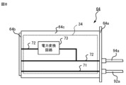
- the power supply board 64 is a plug-in unit and is attached to a front panel 64a having a port to which an emergency brake command line 92a and a control power line 94a can be attached, and a slot 53d. It has a connector 64b and a printed circuit board 64c on which the power supply circuit 34 shown in FIG. 2 is mounted.
- the front panel 64a and connector 64b shown in FIG. 6 function as the interface 85 shown in FIG.
- the power supply board 64 shown in FIGS. 6 and 7 supplies power to the calculation processing board 61, the brake control board 62, and the sliding control board 63.
- the power supply circuit 34 mounted on the printed circuit board 64c of the power supply board 64 electrically connects the emergency brake command line 92a attached to the front panel 64a to the command line 57 via the connector 64b and the slot 53d. It has a pattern wiring 71 that is connected to the main body.
- the voltage value of the DC voltage applied to the command line 57 can be considered to match the voltage value of the DC voltage applied to the emergency brake command line 92a. For example, it can be assumed that a DC voltage of 100V is applied to the command line 57.
- the power supply circuit 34 further includes a pattern wiring 72 that electrically connects a control power supply line 94a attached to the front panel 64a to the power supply lines 55 and 56 via the connector 64b and the slot 53d.
- the power supply circuit 34 further transmits the DC power supplied from the control power supply 94 via the control power supply line 94a to other boards, specifically, at least the arithmetic processing board 61, the brake control board 62, and the sliding control board 63. It has a power conversion circuit 73 that converts into DC power to be supplied to either one.
- the power conversion circuit 73 is, for example, a DC (Direct Current)-DC converter.
- the power supply line 55 is supplied with DC power that is supplied from the control power supply 94 via the control power supply line 94a attached to the front panel 64a, and whose voltage is stepped down by the power conversion circuit 73.
- DC power is supplied to the power supply line 56 from a control power supply 94 via a control power supply line 94a attached to the front panel 64a.
- the voltage value of the DC voltage applied to the command line 57 can be considered to match the voltage value of the DC voltage applied to the emergency brake command line 92a. Therefore, the arithmetic processing module 31 mounted on the arithmetic processing board 61, the brake control circuit 32 mounted on the brake control board 62, and the sliding control circuit 33 mounted on the sliding control board 63 are connected to the emergency brake command line. Even if the emergency brake command line 92a is not directly connected to the emergency brake command line 92a, it is possible to obtain the voltage value of the DC voltage applied to the emergency brake command line 92a.
- the brake control unit 11 performs service brake control and skid control while the voltage value of the DC voltage applied to the emergency brake command line 92a is equal to or higher than the threshold voltage, and controls the DC voltage applied to the emergency brake command line 92a. When the voltage value of the voltage becomes less than the threshold voltage, emergency brake control is performed.
- the threshold voltage may be determined according to the range of values that the DC voltage applied to the emergency brake command line 92a can take when no abnormality occurs in the emergency brake command line 92a. For example, the threshold voltage is a value obtained by multiplying the target value of the output voltage of the emergency brake power source 92 by 0.8.
- the arithmetic processing module 31 mounted on the arithmetic processing board 61 performs service brake control and skiing control while the voltage value of the DC voltage applied to the command line 57 is equal to or higher than the threshold voltage.
- the target brake force determination unit 41 included in the arithmetic processing module 31 shown in FIG. Obtain measurements of the air pressure in the air chamber.
- the target brake force determination unit 41 multiplies the target deceleration indicated by the brake command by the weight of the vehicle obtained from the measured value of the pressure of the air in the air chamber of the air spring. Determine the target brake force.
- the target pressure determining unit 42 determines the target pressing force from the friction coefficient of the contact surface between the brake shoe and the wheel of the mechanical brake device 98 and the target braking force. It is assumed that the target pressure determination unit 42 holds information regarding the friction coefficient in advance.
- the target pressure determination unit 42 determines the target pressure by dividing the target pressing force by the area value of the surface perpendicular to the sliding direction of the piston. It is assumed that the target pressure determination unit 42 holds in advance information about the area value of the surface perpendicular to the sliding direction of the piston.
- the target pressure determined by the target pressure determination unit 42 is sent to the brake control circuit 32 mounted on the brake control board 62 via the system bus 54.
- the skidding determination unit 43 determines whether the difference between at least one shaft speed and the reference shaft speed is equal to or greater than a threshold speed difference. Determine whether If the difference between at least one shaft speed and the reference shaft speed is equal to or greater than the threshold speed difference, it can be considered that skidding has occurred.
- the skidding determination unit 43 If the difference between at least one shaft speed and the reference shaft speed is equal to or greater than the threshold speed difference, the skidding determination unit 43 outputs a skidding determination result indicating that skidding has occurred. If the difference between each axis speed and the reference axis speed is less than the threshold speed difference, the skidding determination unit 43 outputs a skidding determination result indicating that no skidding has occurred.
- the skiing determination result is sent to the skiing control circuit 33 mounted on the skiing control board 63 via the system bus 54.
- the brake control circuit 32 mounted on the brake control board 62 operates according to the target pressure acquired via the system bus 54 while the voltage value of the DC voltage applied to the command line 57 is equal to or higher than the threshold voltage. to control the regular solenoid valve 21.
- the brake control circuit 32 controls the regular solenoid valve 21 by sending a solenoid valve control signal to the regular solenoid valve 21 via the signal line 21a according to the target pressure acquired via the system bus 54.
- the brake control circuit 32 keeps the emergency solenoid valve 23 closed by sending a solenoid valve control signal to the emergency solenoid valve 23 via the signal line 23a.
- the air supplied from the variable load valve 22 is not supplied to the double check valve 24.
- the air output from the regular solenoid valve 21 is sent to the mechanical brake device 98 via the double check valve 24 and the anti-skid valve 97.
- the skiing control circuit 33 mounted on the skiing control board 63 uses the skiing determination result obtained via the system bus 54 while the voltage value of the DC voltage applied to the command line 57 is equal to or higher than the threshold voltage.
- the anti-skid valve 97 is controlled accordingly. Specifically, the skid control circuit 33 opens the skid prevention valve 97 when acquiring a skid determination result indicating that skid has occurred.
- the anti-skid valve 97 opens, the air output from the relay valve 25 is exhausted, and the pressure of the air supplied to the mechanical brake device 98 decreases. This results in reduced braking force and readhesion of the wheels to the rail.
- the skid control circuit 33 obtains the skid determination result indicating that no skidding has occurred, the skid control circuit 33 maintains the skid prevention valve 97 closed. Thereby, the air output from the relay valve 25 is supplied to the mechanical brake device 98 without being exhausted.
- the arithmetic processing module 31 mounted on the arithmetic processing board 61 performs emergency brake control when the voltage value of the DC voltage applied to the command line 57 becomes less than a threshold voltage.
- the target brake force determination unit 41 included in the calculation processing module 31 determines the target brake force in the same manner as in the service brake control, and the target pressure determination unit 42 determines the target brake force in the same manner as in the service brake control. Make pressure determinations.
- the skid determination section 43 does not determine whether or not the vehicle skids as described above.
- the brake control circuit 32 mounted on the brake control board 62 operates regardless of the target pressure acquired via the system bus 54.
- the emergency solenoid valve 23 is opened by sending a solenoid valve control signal to the emergency solenoid valve 23 via the signal line 23a.
- the emergency solenoid valve 23 is opened, the air output from the variable load valve 22 is supplied to the double check valve 24 .
- the pressure of the air output from the emergency solenoid valve 23 is higher than the pressure of the air output from the regular solenoid valve 21, so the air output from the emergency solenoid valve 23 is transferred to the double check valve 24 and the anti-skid valve. 97 to a mechanical brake device 98.
- the skiing control circuit 33 mounted on the skiing control board 63 performs a glide control circuit 33 regardless of the skid determination result obtained via the system bus 54. , keeping the anti-skid valve 97 closed. As a result, skidding control is not performed during emergency brake control.
- the emergency brake command line 92a is connected to the power supply board 64, and is connected to other boards, specifically, the arithmetic processing board 61, the brake control board 62 and is not connected to the sliding control board 63. Therefore, compared to a structure in which emergency brake command lines are connected to a plurality of boards, it is easier to identify the location where an abnormality has occurred in the emergency brake command line 92a. According to the brake control device 1 according to the first embodiment, when an abnormality occurs in the emergency brake command line 92a, it is possible to resolve the situation where the brake operation in the main controller 91 and the actual brake control do not correspond. The time required can be shortened.
- the power supply is based on the DC power supplied from the emergency brake command line 92a to the command line 57 connecting the power supply board 64 and each of the arithmetic processing board 61, the brake control board 62, and the sliding control board 63.
- DC voltage is applied. Therefore, the arithmetic processing module 31 mounted on the arithmetic processing board 61, the brake control circuit 32 mounted on the brake control board 62, and the sliding control circuit 33 mounted on the sliding control board 63 are connected to the emergency brake command line. Even if the emergency brake command line 92a is not directly connected to the emergency brake command line 92a, it is possible to obtain the voltage value of the DC voltage applied to the emergency brake command line 92a. In other words, the arithmetic processing module 31, the brake control circuit 32, and the skid control circuit 33 determine whether or not the emergency brake is operated in the master controller 91, even if they are not directly connected to the emergency brake command line 92a. becomes possible.
- the voltage signal flowing through the signal line 26a connected to the arithmetic processing board 61 is a low voltage signal of, for example, 5V. Since the emergency brake command line 92a to which a high voltage is applied is not connected to the arithmetic processing board 61, the voltage signal flowing through the signal line 26a is affected by electromagnetic noise caused by the high voltage applied to the emergency brake command line 92a. receiving is suppressed.
- the brake control device 2 acquires a driving command from the master controller 91 via the transmission line 91a, the train integrated management device 99, and the transmission line 99a.
- the configuration of the brake control device 2 is similar to the brake control device 1 according to the first embodiment.
- the target value of the output voltage of the control power source 94 is greater than or equal to the target value of the output voltage of the emergency brake power source 92. It is preferable that the control power source 94 is a 100V DC power source similarly to the emergency brake power source 92.
- the brake control unit 12 included in the brake control device 2 further includes a monitoring circuit 35 that monitors the state of the emergency brake command line 92a in addition to the configuration of the brake control unit 11. Specifically, the monitoring circuit 35 repeatedly determines whether or not the voltage value of the voltage applied to the command line 57 is equal to or higher than the threshold voltage at predetermined intervals. As in the first embodiment, the voltage value of the DC voltage applied to the command line 57 can be considered to match the voltage value of the DC voltage applied to the emergency brake command line 92a. Therefore, by monitoring the voltage value of the voltage applied to the command line 57, it is possible to monitor the state of the emergency brake command line 92a.
- the arithmetic processing module 31 includes an abnormality determination section that determines whether or not there is an abnormality in the emergency brake command line 92a. 44.
- the abnormality determination unit 44 determines whether or not the emergency brake command line 92a is disconnected according to the driving command and the determination result of the monitoring circuit 35. For example, the abnormality determination unit 44 determines the voltage applied to the command line 57 when the driving command includes a powering command, or when the driving command is a coasting command that does not include either a powering command or a brake command. It is determined whether the value is greater than or equal to a threshold voltage.
- the driving command includes a power running command
- the driving command does not include a power running command or a brake command
- the voltage value of the voltage applied to the command line 57 is less than the threshold voltage.
- the emergency brake control is being performed even though the emergency brake is not operated in the controller 91.
- the brake control device 2 performs emergency brake control even though the main controller 91 has not operated the emergency brake. Therefore, when the driving command includes a power running command or when the driving command does not include either a power running command or a brake command, when the voltage value of the voltage applied to the command line 57 becomes less than the threshold voltage, the emergency brake is applied. It can be considered that a disconnection has occurred in the command line 92a.
- the abnormality determination unit 44 determines whether the voltage value of the voltage applied to the command line 57 is less than the threshold voltage when the driving command includes a powering command or when the driving command does not include a powering command or a brake command. If it is determined that there is, the power supply circuit 34 is controlled to apply a DC voltage to the command line 57 based on the DC power supplied from the control power supply 94 via the control power supply line 94a.
- the brake control unit 12 is realized by a subrack device, similar to the first embodiment.
- the backplane 52 is provided with a plurality of slots 53a, 53b, 53c, 53d, and 53e.
- the brake control unit 12 further includes a monitoring board 65 attached to the slot 53e.
- the backplane 52 includes a system bus 54 connected to the slots 53a, 53b, 53d, and 53e, power lines 55, 56 electrically connected to the slots 53a, 53b, 53c, 53d, and 53e, and a system bus 54 connected to the slots 53a, 53b, 53d, and 53e.
- a command line 57 electrically connected to 53b, 53c, 53d, and 53e is formed.
- the monitoring board 65 is a plug-in unit and includes a front panel 65a, a connector 65b attached to the slot 53e, and a printed circuit board 65c on which the monitoring circuit 35 is mounted.
- the monitoring circuit 35 has the same hardware configuration as the brake control circuit 32. Specifically, front panel 65a and connector 65b function as interface 85 shown in FIG.
- a DC voltage based on DC power supplied via the emergency brake command line 92a is applied to the command line 57 shown in FIG. 12. Therefore, the monitoring circuit 35 mounted on the monitoring board 65 can obtain the voltage value applied to the emergency brake command line 92a even if it is not directly connected to the emergency brake command line 92a. becomes.
- the power supply board 64 supplies power to the calculation processing board 61, the brake control board 62, the sliding control board 63, and the monitoring board 65.
- the details of the configuration of the power supply board 64 will be explained below.
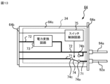
- the power supply circuit 34 mounted on the printed circuit board 64c of the power supply board 64 includes, in addition to the configuration of the power supply circuit 34 in the first embodiment, a switch 74 for switching the connection destination of the command line 57. It further includes a switch control circuit 75 that switches the switch 74.
- the switch 74 has a terminal 74a electrically connected to an emergency brake command line 92a attached to the front panel 64a via pattern wiring 71, and a control power line attached to the front panel 64a via pattern wiring 72. and a terminal 74b electrically connected to the terminal 94a.
- the switch 74 further has a terminal 74c electrically connected to the command line 57 via the pattern wiring 71 and the connector 64b. Terminal 74c is connected to terminal 74a or terminal 74b.
- the switch control circuit 75 switches the connection destination of the terminal 74c according to a command obtained from the arithmetic processing module 31 mounted on the arithmetic processing board 61 via the system bus 54.
- the switch control circuit 75 may switch the switch 74 by adjusting the current flowing through a coil included in the switch 74 formed by a relay according to a command obtained from the arithmetic processing module 31.
- the terminal 74c When the brake control device 1 starts operating, the terminal 74c is connected to the terminal 74a. Thereby, the value of the DC voltage applied to the command line 57 can be considered to match the value of the DC voltage applied to the emergency brake command line 92a.
- DC power is supplied to the power line 55 from the control power source 94 via the control power line 94a attached to the front panel 64a, and the voltage is stepped down by the power conversion circuit 73.
- DC power is supplied to the power supply line 56 from a control power supply 94 via a control power supply line 94a attached to the front panel 64a.
- the abnormality determination unit 44 determines the voltage value of the voltage applied to the command line 57 when the driving command includes a powering command or when the driving command does not include either a powering command or a brake command. It is determined whether or not is equal to or higher than a threshold voltage. The abnormality determination unit 44 determines whether the voltage value of the voltage applied to the command line 57 is less than the threshold voltage when the driving command includes a powering command or when the driving command does not include a powering command or a brake command. If it is determined that there is, a notification is sent to the switch control circuit 75 of the power supply circuit 34 via the system bus 54 to the effect that an abnormality has occurred in the emergency brake command line 92a.
- the switch control circuit 75 When the switch control circuit 75 receives notification of an abnormality in the emergency brake command line 92a, it connects the terminal 74c to the terminal 74b. Thereby, the DC power supplied from the control power supply 94 via the control power supply line 94a is supplied to the command line 57. If the output voltage value of the control power source 94 is greater than or equal to the output voltage value of the emergency brake power source 92, the voltage applied to the command line 57 will be greater than or equal to the threshold voltage. As a result, the brake control circuit 32 ends the emergency brake control. This eliminates the situation where the brake operation in the main controller 91 and the actual brake control do not correspond.
- the power supply line 55 is supplied with DC power that is supplied from the control power supply 94 via the control power supply line 94a and stepped down by the power conversion circuit 73, and the power supply line 56 is supplied with DC power is supplied from the control power supply 94 via the control power supply line 94a.
- the power supply circuit 34 receives the direct current supplied from the control power supply 94 via the control power supply line 94a.
- a DC voltage is applied to the command line 57 based on the electric power.
- Embodiment 3 The abnormality in the emergency brake command line 92a is not limited to a disconnection.
- Embodiment 3 describes a brake control unit 12 that includes an arithmetic processing module 31 having an abnormality determination section 44 that determines not only whether the emergency brake command line 92a is disconnected but also whether the emergency brake command line 92a is short-circuited.
- the configurations of the brake control unit 12 and the arithmetic processing module 31 are the same as in the second embodiment.
- an emergency brake command line 92a connected to an emergency brake power source 92 is routed through all vehicles, branched off in each vehicle, and connected to the brake control device 2 provided in each vehicle. Ru. If an abnormality occurs in the branched emergency brake command line 92a, it is possible to determine whether there is an abnormality by comparing the state of the emergency brake command line 92a in another vehicle. In Embodiment 3, determination of whether or not there is an abnormality in the emergency brake command line 92a will be described using as an example a railway vehicle composed of three or more vehicles.
- the monitoring circuit 35 repeatedly determines whether the voltage value of the voltage applied to the command line 57 is equal to or higher than the threshold voltage at predetermined intervals.
- the abnormality determination unit 44 transmits the determination result obtained from the monitoring circuit 35 to the train integrated management device 99.
- the abnormality determination unit 44 acquires, from the train integrated management device 99, the determination result by the monitoring circuit 35 included in the brake control unit 12 included in the brake control device 2 provided in another vehicle.
- the abnormality determination unit 44 compares the determination result acquired from the monitoring circuit 35 with the determination result obtained by the monitoring circuit 35 in other vehicles acquired from the train integrated management device 99, and determines whether there is an abnormality in the emergency brake command line 92a. do.
- the abnormality determination unit 44 determines whether or not the determination result obtained from the monitoring circuit 35 matches each of the determination results obtained by the monitoring circuit 35 of a plurality of other vehicles acquired from the train integrated management device 99. . If the determination result obtained from the monitoring circuit 35 matches at least one of the determination results obtained by the monitoring circuit 35 for a plurality of other vehicles obtained from the train integrated management device 99, no abnormality has occurred in the emergency brake command line 92a. It can be considered as
- the determination result obtained from the monitoring circuit 35 does not match any of the determination results obtained by the monitoring circuit 35 for a plurality of other vehicles obtained from the train integrated management device 99, an abnormality has occurred in the emergency brake command line 92a. It can be assumed that there is.
- the determination result obtained from the monitoring circuit 35 indicates that the voltage value of the voltage applied to the command line 57 is equal to or higher than the threshold voltage, and If all the determination results in the monitoring circuit 35 indicate that the voltage value of the voltage applied to the command line 57 is less than the threshold voltage, it is assumed that a short circuit has occurred in the emergency brake command line 92a. Can be done.
- the determination result obtained from the monitoring circuit 35 indicates that the voltage value of the voltage applied to the command line 57 is less than the threshold voltage, and the monitoring circuit 35 in the other plurality of vehicles obtained from the train integrated management device 99 If both of the determination results indicate that the voltage value of the voltage applied to the command line 57 is equal to or higher than the threshold voltage, it can be considered that a break in the emergency brake command line 92a has occurred.
- the power supply circuit 34 mounted on the printed circuit board 64c of the power supply board 64 has a switch 76 that switches the connection destination of the command line 57.
- the switch 76 is switched by the switch control circuit 75.
- the switch 76 has a terminal 76a electrically connected to an emergency brake command line 92a attached to the front panel 64a via a pattern wiring 71, and a control power line attached to the front panel 64a via a pattern wiring 72. and a terminal 76b electrically connected to the terminal 94a.
- the switch 76 further includes a terminal 76c electrically connected to the command line 57 via the pattern wiring 71 and the connector 64b, and a ground terminal 76d that is grounded. Terminal 76c is connected to terminal 76a, terminal 76b, or ground terminal 76d.
- the switch control circuit 75 switches the connection destination of the terminal 76c in response to a notification obtained from the arithmetic processing module 31 mounted on the arithmetic processing board 61 via the system bus 54.
- the terminal 76c When the brake control device 2 starts operating, the terminal 76c is connected to the terminal 76a. Thereby, the value of the DC voltage applied to the command line 57 can be considered to match the value of the DC voltage applied to the emergency brake command line 92a.
- DC power is supplied from the control power supply 94 via the control power supply line 94a attached to the front panel 64a, and the voltage is stepped down by the power conversion circuit 73.
- DC power is supplied to the power supply line 56 from a control power supply 94 via a control power supply line 94a attached to the front panel 64a.
- the brake control circuit 32 When a disconnection occurs in the emergency brake command line 92a, the DC voltage applied to the command line 57 falls below the threshold voltage, so the brake control circuit 32 performs emergency brake control as in the first embodiment. As a result, the emergency brake control is performed in the main controller 91 even though the emergency brake is not operated.
- a recovery operation performed by the brake control device 2 in order to resolve the situation where the brake operation in the main controller 91 and the actual brake control do not correspond will be described below.
- the abnormality determination unit 44 determines whether the determination result obtained from the monitoring circuit 35 matches each of the determination results obtained by the monitoring circuit 35 of a plurality of other vehicles obtained from the train integrated management device 99. Determine.
- the abnormality determination unit 44 determines that the determination result obtained from the monitoring circuit 35 indicates that the voltage value of the voltage applied to the command line 57 is less than the threshold voltage, and that If the determination results in the monitoring circuit 35 in the vehicle indicate that the voltage value of the voltage applied to the command line 57 is equal to or higher than the threshold voltage, switch control of the power supply circuit 34 is performed via the system bus 54. The circuit 75 is notified that the emergency brake command line 92a is disconnected.
- the switch control circuit 75 When the switch control circuit 75 receives a notification that the emergency brake command line 92a is disconnected, it connects the terminal 76c to the terminal 76b. Thereby, the DC power supplied from the control power supply 94 via the control power supply line 94a is supplied to the command line 57. If the output voltage value of the control power source 94 is greater than or equal to the output voltage value of the emergency brake power source 92, the voltage applied to the command line 57 will be greater than or equal to the threshold voltage. As a result, the brake control circuit 32 ends the emergency brake control. This eliminates the situation where the brake operation in the main controller 91 and the actual brake control do not correspond.
- the abnormality determination unit 44 determines that the determination result obtained from the monitoring circuit 35 indicates that the voltage value of the voltage applied to the command line 57 is equal to or higher than the threshold voltage, and that If the determination results of the monitoring circuit 35 in the vehicle indicate that the voltage value of the voltage applied to the command line 57 is less than the threshold voltage, switch control of the power supply circuit 34 is performed via the system bus 54. The circuit 75 is notified that a short circuit has occurred in the emergency brake command line 92a.
- the switch control circuit 75 When the switch control circuit 75 receives a notification that a short circuit has occurred in the emergency brake command line 92a, it connects the terminal 76c to the ground terminal 76d. Thereby, the command line 57 is electrically disconnected from the emergency brake command line 92a. Specifically, the command line 57 is grounded. As a result, the voltage applied to the command line 57 becomes less than the threshold voltage, so the brake control circuit 32 starts emergency brake control. This eliminates the situation where the brake operation in the main controller 91 and the actual brake control do not correspond.
- the power supply line 55 is supplied with DC power that is supplied from the control power supply 94 via the control power supply line 94a and stepped down by the power conversion circuit 73, and the power supply line 56 is supplied with DC power is supplied from the control power supply 94 via the control power supply line 94a.
- the power supply circuit 34 receives the direct current supplied from the control power supply 94 via the control power supply line 94a.
- a DC voltage is applied to the command line 57 based on the electric power.
- the power supply circuit 34 connects the command line 57 to the ground terminal 76d. As a result, it is possible to prevent the actual braking force from falling below the desired braking force during emergency braking due to short circuiting of the emergency brake command line 92a.
- a state in which the brake operation in the main controller 91 does not correspond to the actual brake control may occur not only due to an abnormality in the emergency brake command line 92a but also due to an abnormality in the control power supply line 94a. If an abnormality occurs in the control power supply line 94a, specifically, if the control power supply line 94a is disconnected, DC power will not be supplied from the control power supply 94 to the brake control unit 11, making it impossible to perform brake control.
- Embodiment 4 Differences from Embodiment 1 regarding the brake control device having a structure for resolving the situation where the brake operation in the driver's cab does not correspond to the actual brake control when the control power supply line 94a is disconnected. will be mainly described in Embodiment 4.
- the structure of the brake control device 1 according to the fourth embodiment is similar to the brake control device 1 according to the first embodiment.
- the power supply circuit 34 mounted on the printed circuit board 64c of the power supply board 64 further includes a switch 77 for switching connection destinations of the power supply lines 55 and 56, and a switch control circuit 78 for switching the switch 77. .
- the switch 77 has a terminal 77a electrically connected to a control power supply line 94a attached to the front panel 64a via pattern wiring 72, and an emergency brake command line attached to the front panel 64a via pattern wiring 71. and a terminal 77b electrically connected to the terminal 92a.
- the switch 77 is further electrically connected to the power line 55 via the pattern wiring 72, the power conversion circuit 73, and the connector 64b, and has a terminal electrically connected to the power line 56 via the pattern wiring 72 and the connector 64b. It has 77c. Terminal 77c is connected to terminal 77a or terminal 77b.
- the switch control circuit 78 is driven by DC power supplied from the emergency brake power supply 92 via the emergency power supply line 92a, and is driven by the voltage value of the DC power supplied from the control power supply 94 via the control power supply line 94a.
- the connection destination of the terminal 76c is switched according to the change.
- the terminal 77c is connected to the terminal 77a.
- DC power is supplied to the power line 55 from the control power supply 94 via the control power supply line 94a attached to the front panel 64a, and the DC power is stepped down by the power conversion circuit 73. Supplied.
- DC power is supplied to the power supply line 56 from a control power supply 94 via a control power supply line 94a attached to the front panel 64a.
- the value of the DC voltage applied to the command line 57 can be considered to match the value of the DC voltage applied to the emergency brake command line 92a.
- the brake control device 1 when the control power supply line 94a is disconnected, the power supply circuit 34 is supplied with power from the emergency brake power supply 92 via the emergency brake command line 92a. DC power based on DC power is supplied to power supply lines 55 and 56. As a result, even if a disconnection occurs in the control power supply line 94a, the brake control device 1 can continue brake control.
- the present disclosure is not limited to the embodiments described above.
- the method for determining whether there is an abnormality in the emergency brake command line 92a is not limited to the above-mentioned example.
- the brake control unit 12 included in the brake control device 2 according to the second embodiment does not include the monitoring circuit 35, and the arithmetic processing module 31 performs emergency control according to the operation command and the air pressure output by the relay valve 25. It may also be determined whether or not the brake command line 92a is disconnected.
- the abnormality determination unit 44 acquires an operation command from the train integrated management device 99, and acquires the measured value of the air pressure output by the relay valve 25 from the pressure sensor 26.
- the abnormality determination unit 44 determines whether the measured value of the air pressure output by the relay valve 25 is equal to or higher than a threshold pressure when the driving command includes a powering command or when the driving command does not include a powering command or a brake command. Determine whether it exists or not.
- the threshold pressure is a value higher than the upper limit of the range of possible values of the measured value of the air pressure output by the relay valve 25 during service brake control.
- the abnormality determination unit 44 determines whether the driving command includes a powering command or if the driving command does not include a powering command or a brake command. It is preferable to determine whether the measured value of the air pressure output by the relay valve 25 continues to be equal to or higher than a threshold pressure for a predetermined determination period or not. The determination period is long enough to prevent erroneous determination due to fluctuations in the pressure of the air output by the relay valve 25.
- the brake control device 1 may obtain the driving command from the train integrated management device 99 similarly to Embodiment 2-4.
- the structure of the brake control devices 1 and 2 is not limited to the above example.
- the brake control devices 1 and 2 may not include the sliding control board 63.
- the brake control devices 1 and 2 may further include a board corresponding to other functions.
- the processing of the brake control units 11 and 12 during emergency braking is not limited to the above example.
- the skid control circuit 33 may perform skid control during emergency braking as well as during regular braking.
- the skid control circuit 33 may adjust the opening degree of the anti-skid valve 97 to be smaller during emergency braking than during regular braking.
- the arrangement order of the arithmetic processing board 61, brake control board 62, sliding control board 63, and power supply board 64 is not limited to the above-mentioned example, but is arbitrary.
- the arrangement position of the monitoring board 65 is not limited to the above-mentioned example, but is arbitrary.
- the number of slots provided in the backplane 52 is not limited to the above example and is arbitrary.
- the number of power supply lines provided on the backplane 52 is not limited to the above example and is arbitrary.
- the abnormality determination unit 44 may be realized as a function of the train integrated management device 99.
- the train integrated management device 99 may output the determination result obtained from the abnormality determination unit 44 to, for example, a display device provided in the driver's cab.
Landscapes
- Engineering & Computer Science (AREA)
- Transportation (AREA)
- Mechanical Engineering (AREA)
- Regulating Braking Force (AREA)
- Electric Propulsion And Braking For Vehicles (AREA)
- Valves And Accessory Devices For Braking Systems (AREA)
Priority Applications (3)
| Application Number | Priority Date | Filing Date | Title |
|---|---|---|---|
| PCT/JP2022/023861 WO2023242966A1 (ja) | 2022-06-14 | 2022-06-14 | ブレーキ制御装置 |
| JP2024527966A JP7558457B2 (ja) | 2022-06-14 | 2022-06-14 | ブレーキ制御装置 |
| DE112022007369.1T DE112022007369T5 (de) | 2022-06-14 | 2022-06-14 | Bremsensteuerungseinrichtung |
Applications Claiming Priority (1)
| Application Number | Priority Date | Filing Date | Title |
|---|---|---|---|
| PCT/JP2022/023861 WO2023242966A1 (ja) | 2022-06-14 | 2022-06-14 | ブレーキ制御装置 |
Publications (1)
| Publication Number | Publication Date |
|---|---|
| WO2023242966A1 true WO2023242966A1 (ja) | 2023-12-21 |
Family
ID=89192708
Family Applications (1)
| Application Number | Title | Priority Date | Filing Date |
|---|---|---|---|
| PCT/JP2022/023861 Ceased WO2023242966A1 (ja) | 2022-06-14 | 2022-06-14 | ブレーキ制御装置 |
Country Status (3)
| Country | Link |
|---|---|
| JP (1) | JP7558457B2 (https=) |
| DE (1) | DE112022007369T5 (https=) |
| WO (1) | WO2023242966A1 (https=) |
Citations (3)
| Publication number | Priority date | Publication date | Assignee | Title |
|---|---|---|---|---|
| JPH10338123A (ja) * | 1997-06-06 | 1998-12-22 | Nabco Ltd | 鉄道車両用ブレーキ装置 |
| US20020034058A1 (en) * | 2000-09-15 | 2002-03-21 | New York Air Brake Corporation | Trainline communication controller assembly |
| US6472769B1 (en) * | 2000-09-14 | 2002-10-29 | New York Air Brake Corporation | Car control device assembly |
Family Cites Families (1)
| Publication number | Priority date | Publication date | Assignee | Title |
|---|---|---|---|---|
| JP5749460B2 (ja) | 2010-07-29 | 2015-07-15 | 日本信号株式会社 | ブレーキ制御システム |
-
2022
- 2022-06-14 WO PCT/JP2022/023861 patent/WO2023242966A1/ja not_active Ceased
- 2022-06-14 DE DE112022007369.1T patent/DE112022007369T5/de active Pending
- 2022-06-14 JP JP2024527966A patent/JP7558457B2/ja active Active
Patent Citations (3)
| Publication number | Priority date | Publication date | Assignee | Title |
|---|---|---|---|---|
| JPH10338123A (ja) * | 1997-06-06 | 1998-12-22 | Nabco Ltd | 鉄道車両用ブレーキ装置 |
| US6472769B1 (en) * | 2000-09-14 | 2002-10-29 | New York Air Brake Corporation | Car control device assembly |
| US20020034058A1 (en) * | 2000-09-15 | 2002-03-21 | New York Air Brake Corporation | Trainline communication controller assembly |
Also Published As
| Publication number | Publication date |
|---|---|
| JPWO2023242966A1 (https=) | 2023-12-21 |
| DE112022007369T5 (de) | 2025-03-27 |
| JP7558457B2 (ja) | 2024-09-30 |
Similar Documents
| Publication | Publication Date | Title |
|---|---|---|
| KR100274297B1 (ko) | 차량용 전자식 브레이크 장치 | |
| US7784879B2 (en) | Electronic control air management with parking brake and trailer supply control | |
| JP2011518065A (ja) | 車両用制動システム | |
| CN107792032B (zh) | 线控制动系统 | |
| US8152243B2 (en) | Electrically controlled brake system | |
| US12384343B2 (en) | Electrically controllable pneumatic brake system having a two-channel pressure modulator system | |
| US6296325B1 (en) | Method to connect and distribute power to an electromechanical braking system | |
| JP4503131B2 (ja) | 車両における分散形制御装置の作動装置 | |
| US11938912B2 (en) | Redundancy architecture for systems of high-level automation | |
| US7359786B2 (en) | Control and power supply network for vehicle braking system | |
| KR20190104563A (ko) | 자동차용 브레이크 시스템 및 브레이크 시스템을 작동하기 위한 방법 | |
| CN107792041B (zh) | 线控制动系统 | |
| EP3604059A1 (en) | Vehicular brake system | |
| US12194979B2 (en) | Redundant PLC signals evaluation | |
| JPH10503446A (ja) | 制動力の電気的な分配制御を伴うブレーキ装置のための回路 | |
| CN115230654A (zh) | 用于车辆的制动系统 | |
| KR20220170460A (ko) | 차량용 제동장치 | |
| US20100314207A1 (en) | Actuator device and method for controlling the actuator device | |
| CN110799394B (zh) | 车辆用制动系统 | |
| WO2023242966A1 (ja) | ブレーキ制御装置 | |
| US20050275281A1 (en) | Modular braking system | |
| KR102845269B1 (ko) | 전동식 브레이크 장치 및 제어방법 | |
| JP2019142477A (ja) | 電気機械式のブレーキ力増幅手段を備えた、電子式にスリップ制御可能な車両ブレーキ装置でブレーキ力を増幅するための方法 | |
| CN114599560B (zh) | 用于车辆的电制动系统 | |
| CN115743070A (zh) | 用于在载具中机电地激活制动作用的控制系统以及载具 |
Legal Events
| Date | Code | Title | Description |
|---|---|---|---|
| 121 | Ep: the epo has been informed by wipo that ep was designated in this application |
Ref document number: 22946786 Country of ref document: EP Kind code of ref document: A1 |
|
| ENP | Entry into the national phase |
Ref document number: 2024527966 Country of ref document: JP Kind code of ref document: A |
|
| WWE | Wipo information: entry into national phase |
Ref document number: 202447085421 Country of ref document: IN |
|
| WWE | Wipo information: entry into national phase |
Ref document number: 112022007369 Country of ref document: DE |
|
| WWP | Wipo information: published in national office |
Ref document number: 112022007369 Country of ref document: DE |
|
| 122 | Ep: pct application non-entry in european phase |
Ref document number: 22946786 Country of ref document: EP Kind code of ref document: A1 |