EP3604059A1 - Vehicular brake system - Google Patents
Vehicular brake system Download PDFInfo
- Publication number
- EP3604059A1 EP3604059A1 EP18775759.6A EP18775759A EP3604059A1 EP 3604059 A1 EP3604059 A1 EP 3604059A1 EP 18775759 A EP18775759 A EP 18775759A EP 3604059 A1 EP3604059 A1 EP 3604059A1
- Authority
- EP
- European Patent Office
- Prior art keywords
- controllers
- controller
- braking force
- normal
- unit
- Prior art date
- Legal status (The legal status is an assumption and is not a legal conclusion. Google has not performed a legal analysis and makes no representation as to the accuracy of the status listed.)
- Granted
Links
- 238000001514 detection method Methods 0.000 description 15
- 230000006399 behavior Effects 0.000 description 11
- 238000010586 diagram Methods 0.000 description 6
- 230000007246 mechanism Effects 0.000 description 6
- 238000004891 communication Methods 0.000 description 3
- 230000009467 reduction Effects 0.000 description 3
- 230000000694 effects Effects 0.000 description 2
- 230000002457 bidirectional effect Effects 0.000 description 1
- 230000005540 biological transmission Effects 0.000 description 1
- 210000000078 claw Anatomy 0.000 description 1
- 238000000034 method Methods 0.000 description 1
- 238000012986 modification Methods 0.000 description 1
- 230000004048 modification Effects 0.000 description 1
- 230000004044 response Effects 0.000 description 1
- 230000006641 stabilisation Effects 0.000 description 1
- 238000011105 stabilization Methods 0.000 description 1
- 229920003002 synthetic resin Polymers 0.000 description 1
- 239000000057 synthetic resin Substances 0.000 description 1
Images


Classifications
-
- B—PERFORMING OPERATIONS; TRANSPORTING
- B60—VEHICLES IN GENERAL
- B60T—VEHICLE BRAKE CONTROL SYSTEMS OR PARTS THEREOF; BRAKE CONTROL SYSTEMS OR PARTS THEREOF, IN GENERAL; ARRANGEMENT OF BRAKING ELEMENTS ON VEHICLES IN GENERAL; PORTABLE DEVICES FOR PREVENTING UNWANTED MOVEMENT OF VEHICLES; VEHICLE MODIFICATIONS TO FACILITATE COOLING OF BRAKES
- B60T13/00—Transmitting braking action from initiating means to ultimate brake actuator with power assistance or drive; Brake systems incorporating such transmitting means, e.g. air-pressure brake systems
- B60T13/74—Transmitting braking action from initiating means to ultimate brake actuator with power assistance or drive; Brake systems incorporating such transmitting means, e.g. air-pressure brake systems with electrical assistance or drive
- B60T13/741—Transmitting braking action from initiating means to ultimate brake actuator with power assistance or drive; Brake systems incorporating such transmitting means, e.g. air-pressure brake systems with electrical assistance or drive acting on an ultimate actuator
-
- B—PERFORMING OPERATIONS; TRANSPORTING
- B60—VEHICLES IN GENERAL
- B60T—VEHICLE BRAKE CONTROL SYSTEMS OR PARTS THEREOF; BRAKE CONTROL SYSTEMS OR PARTS THEREOF, IN GENERAL; ARRANGEMENT OF BRAKING ELEMENTS ON VEHICLES IN GENERAL; PORTABLE DEVICES FOR PREVENTING UNWANTED MOVEMENT OF VEHICLES; VEHICLE MODIFICATIONS TO FACILITATE COOLING OF BRAKES
- B60T8/00—Arrangements for adjusting wheel-braking force to meet varying vehicular or ground-surface conditions, e.g. limiting or varying distribution of braking force
- B60T8/17—Using electrical or electronic regulation means to control braking
-
- B—PERFORMING OPERATIONS; TRANSPORTING
- B60—VEHICLES IN GENERAL
- B60T—VEHICLE BRAKE CONTROL SYSTEMS OR PARTS THEREOF; BRAKE CONTROL SYSTEMS OR PARTS THEREOF, IN GENERAL; ARRANGEMENT OF BRAKING ELEMENTS ON VEHICLES IN GENERAL; PORTABLE DEVICES FOR PREVENTING UNWANTED MOVEMENT OF VEHICLES; VEHICLE MODIFICATIONS TO FACILITATE COOLING OF BRAKES
- B60T1/00—Arrangements of braking elements, i.e. of those parts where braking effect occurs specially for vehicles
- B60T1/02—Arrangements of braking elements, i.e. of those parts where braking effect occurs specially for vehicles acting by retarding wheels
- B60T1/06—Arrangements of braking elements, i.e. of those parts where braking effect occurs specially for vehicles acting by retarding wheels acting otherwise than on tread, e.g. employing rim, drum, disc, or transmission or on double wheels
- B60T1/065—Arrangements of braking elements, i.e. of those parts where braking effect occurs specially for vehicles acting by retarding wheels acting otherwise than on tread, e.g. employing rim, drum, disc, or transmission or on double wheels employing disc
-
- B—PERFORMING OPERATIONS; TRANSPORTING
- B60—VEHICLES IN GENERAL
- B60T—VEHICLE BRAKE CONTROL SYSTEMS OR PARTS THEREOF; BRAKE CONTROL SYSTEMS OR PARTS THEREOF, IN GENERAL; ARRANGEMENT OF BRAKING ELEMENTS ON VEHICLES IN GENERAL; PORTABLE DEVICES FOR PREVENTING UNWANTED MOVEMENT OF VEHICLES; VEHICLE MODIFICATIONS TO FACILITATE COOLING OF BRAKES
- B60T13/00—Transmitting braking action from initiating means to ultimate brake actuator with power assistance or drive; Brake systems incorporating such transmitting means, e.g. air-pressure brake systems
- B60T13/74—Transmitting braking action from initiating means to ultimate brake actuator with power assistance or drive; Brake systems incorporating such transmitting means, e.g. air-pressure brake systems with electrical assistance or drive
-
- B—PERFORMING OPERATIONS; TRANSPORTING
- B60—VEHICLES IN GENERAL
- B60T—VEHICLE BRAKE CONTROL SYSTEMS OR PARTS THEREOF; BRAKE CONTROL SYSTEMS OR PARTS THEREOF, IN GENERAL; ARRANGEMENT OF BRAKING ELEMENTS ON VEHICLES IN GENERAL; PORTABLE DEVICES FOR PREVENTING UNWANTED MOVEMENT OF VEHICLES; VEHICLE MODIFICATIONS TO FACILITATE COOLING OF BRAKES
- B60T17/00—Component parts, details, or accessories of power brake systems not covered by groups B60T8/00, B60T13/00 or B60T15/00, or presenting other characteristic features
- B60T17/18—Safety devices; Monitoring
- B60T17/22—Devices for monitoring or checking brake systems; Signal devices
- B60T17/221—Procedure or apparatus for checking or keeping in a correct functioning condition of brake systems
-
- B—PERFORMING OPERATIONS; TRANSPORTING
- B60—VEHICLES IN GENERAL
- B60T—VEHICLE BRAKE CONTROL SYSTEMS OR PARTS THEREOF; BRAKE CONTROL SYSTEMS OR PARTS THEREOF, IN GENERAL; ARRANGEMENT OF BRAKING ELEMENTS ON VEHICLES IN GENERAL; PORTABLE DEVICES FOR PREVENTING UNWANTED MOVEMENT OF VEHICLES; VEHICLE MODIFICATIONS TO FACILITATE COOLING OF BRAKES
- B60T7/00—Brake-action initiating means
- B60T7/02—Brake-action initiating means for personal initiation
- B60T7/04—Brake-action initiating means for personal initiation foot actuated
- B60T7/042—Brake-action initiating means for personal initiation foot actuated by electrical means, e.g. using travel or force sensors
-
- B—PERFORMING OPERATIONS; TRANSPORTING
- B60—VEHICLES IN GENERAL
- B60T—VEHICLE BRAKE CONTROL SYSTEMS OR PARTS THEREOF; BRAKE CONTROL SYSTEMS OR PARTS THEREOF, IN GENERAL; ARRANGEMENT OF BRAKING ELEMENTS ON VEHICLES IN GENERAL; PORTABLE DEVICES FOR PREVENTING UNWANTED MOVEMENT OF VEHICLES; VEHICLE MODIFICATIONS TO FACILITATE COOLING OF BRAKES
- B60T2270/00—Further aspects of brake control systems not otherwise provided for
- B60T2270/40—Failsafe aspects of brake control systems
- B60T2270/402—Back-up
-
- B—PERFORMING OPERATIONS; TRANSPORTING
- B60—VEHICLES IN GENERAL
- B60T—VEHICLE BRAKE CONTROL SYSTEMS OR PARTS THEREOF; BRAKE CONTROL SYSTEMS OR PARTS THEREOF, IN GENERAL; ARRANGEMENT OF BRAKING ELEMENTS ON VEHICLES IN GENERAL; PORTABLE DEVICES FOR PREVENTING UNWANTED MOVEMENT OF VEHICLES; VEHICLE MODIFICATIONS TO FACILITATE COOLING OF BRAKES
- B60T2270/00—Further aspects of brake control systems not otherwise provided for
- B60T2270/40—Failsafe aspects of brake control systems
- B60T2270/413—Plausibility monitoring, cross check, redundancy
-
- B—PERFORMING OPERATIONS; TRANSPORTING
- B60—VEHICLES IN GENERAL
- B60T—VEHICLE BRAKE CONTROL SYSTEMS OR PARTS THEREOF; BRAKE CONTROL SYSTEMS OR PARTS THEREOF, IN GENERAL; ARRANGEMENT OF BRAKING ELEMENTS ON VEHICLES IN GENERAL; PORTABLE DEVICES FOR PREVENTING UNWANTED MOVEMENT OF VEHICLES; VEHICLE MODIFICATIONS TO FACILITATE COOLING OF BRAKES
- B60T2270/00—Further aspects of brake control systems not otherwise provided for
- B60T2270/82—Brake-by-Wire, EHB
Definitions
- the present invention relates to a vehicle brake system provided with an electric brake.
- a system including two central modules (central control devices), four wheel modules (wheel control devices), and an input device (PTL 1).
- the two central modules each control two wheel modules.
- the two central control devices monitor each other, and the central control device, when a failure occurs, disconnects the wheel control device from a power supply.
- the system does not monitor a wheel control device provided with an antilock function or an antiskid function.
- An object of the invention is to provide a vehicle brake system provided with an electric brake, which is a vehicle brake system with high reliability.
- the invention has been made to achieve at least part of the above object, and can be achieved as the following embodiments or the application examples.
- each of the controllers determines whether itself is normal based on a braking force calculation result of its own, and blocks an output of the controller that is determined to be not normal by self-determination, thus further improving reliability of the braking force calculation results.
- a vehicle brake system includes an electric brake including at least one unit of an electric actuator that presses a friction pad toward a rotor side, a driver that drives the electric actuator, and a control device.
- the control device includes at least three units of controllers connected to one another.
- the controller includes a driver control unit that controls the driver, and a braking force calculation unit that calculates braking force of the electric brake.
- At least one of the controllers further includes a determination unit that compares braking force calculation results of the controllers to determine whether a controller is normal or not.
- the determination unit includes an output block section that blocks, when the determination unit determines that any one of the controllers is not normal, an output of the controller that is determined to be not normal.
- FIG. 1 is an overall configuration diagram illustrating the vehicle brake system 1 according to the embodiment.
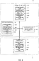
- FIG. 2 is a block diagram illustrating a master controller 30, first and second sub-controllers 40 and 41, and a slave controller 50 of the vehicle brake system 1 according to the embodiment.
- the vehicle brake system 1 includes electric brakes 16a to 16d including at least one unit of motors 80 to 85 being an electric actuator that presses a non-illustrated friction pad toward a non-illustrated rotor side, control devices (10 and 11) including drivers 60 to 65 that drive the motors 80 to 85 and a plurality of controllers (the master controller 30, the first sub-controller 40, the second sub-controller 41, the slave controller 50) connected to one another.
- the non-illustrated rotors which are provided to the wheels Wa to Wd of a vehicle VB being a four-wheeled vehicle, rotate integrally with the wheels Wa to Wd.
- the vehicle VB is not limited to a four-wheeled vehicle.
- a plurality of motors may be provided to one electric brake, or a plurality of electric brakes may be provided to one wheel.
- the electric brake 16a provided to the wheel Wa at the front-wheel left-side (FL) includes a brake caliper 5a, the motors 80 and 81 fixed to the brake caliper 5a via a decelerator 4a, and a load sensor 6a that detects a load applied from the motors 80 and 81 to the non-illustrated friction pads.
- the motor 80 includes a rotation angle sensor 90 that detects the relative position of the rotation axis with respect to the stator of its own.
- the motor 81 which is coaxial with the motor 80, does not need a rotation angle sensor.
- the detection signal from the load sensor 6a is input into the first sub-controller 40, and the detection signal from the rotation angle sensor 90 is input into the first sub-controller 40 and the master controller 30 via the drivers 60 and 61.
- the electric brake 16b provided to the wheel Wb at the front-wheel right-side (FR) includes a brake caliper 5b, the motors 82 and 83 fixed to the brake caliper 5b via a decelerator 4b, and a load sensor 6b that detects a load applied from the motors 82 and 83 to the non-illustrated friction pads.
- the motor 82 includes a rotation angle sensor 92 that detects the relative position of the rotation axis with respect to the stator of its own.
- the motor 83 which is coaxial with the motor 82, does not need a rotation angle sensor.
- the detection signal from the load sensor 6b is input into the slave controller 50, and the detection signal from the rotation angle sensor 92 is input into the slave controller 50 and the master controller 30 via the drivers 62 and 63.
- the electric brake 16c provided to the wheel Wc at the rear-wheel left-side (RL) includes a brake caliper 5c, the motor 84 fixed to the brake caliper 5c via a decelerator 4c, and a load sensor 6c that detects a load applied from the motor 84 to the non-illustrated friction pads.
- the motor 84 includes a rotation angle sensor 94 that detects the relative position of the rotation axis with respect to the stator of its own. The detection signal from the load sensor 6c is input into the second sub-controller 41, and the detection signal from the rotation angle sensor 94 is input into the second sub-controller 41 via the driver 64.
- the electric brake 16d provided to the wheel Wd at the rear-wheel right-side (RR) includes a brake caliper 5d, the motor 85 fixed to the brake caliper 5d via a decelerator 4d, and a load sensor 6d that detects a load applied from the motor 85 to the non-illustrated friction pads.
- the motor 85 includes a rotation angle sensor 95 that detects the relative position of the rotation axis with respect to the stator of its own. The detection signal from the load sensor 6d is input into the second sub-controller 41, and the detection signal from the rotation angle sensor 95 is input into the second sub-controller 41 via the driver 65.
- the brake calipers 5a to 5d are formed in a substantially C-shape, and are integrally provided with a claw portion extending to the opposite side across a non-illustrated rotor.
- the decelerators 4a to 4d which is fixed to the brake calipers 5a to 5d, transmit torque generated by the rotation of the motors 80 to 85 to non-illustrated linear motion mechanisms that are built into the brake calipers 5a to 5d.
- the linear motion mechanism can employ a publicly known mechanism in the electric brake.
- the linear motion mechanism converts the rotation of the motors 80 to 85 into a linear motion of the friction pads via the decelerators 4a to 4d.
- the linear motion mechanism presses the friction pads against the rotor to suppress the rotation of the wheels Wa to Wd.
- the motors 80 to 85 can employ a publicly known electric motor, which is, for example, a brushless DC motor. Driving of the motor 80 to 85 causes the friction pads to move via the decelerators 4a to 4d and the linear motion mechanisms.
- a motor is employed as the electric actuator, however, other publicly known actuators may be employed without being limited thereto.
- the vehicle brake system 1 includes a brake pedal 2 being an input device, and a stroke simulator 3 connected to the brake pedal 2.
- the brake pedal 2 includes a second stroke sensor 21 and a third stroke sensor 22 that detect the operation amount of the brake pedal 2 of the driver.
- the stroke simulator 3 includes a first stroke sensor 20 that detects the operation amount of the brake pedal 2.
- Each of the stroke sensors 20 to 22 mutually independently generates an electrical detection signal corresponding to a depression stroke and/or a depression force being a kind of the operation amount of the brake pedal 2.
- the first stroke sensor 20 sends the detection signal to the master controller 30 to be described below.
- the second stroke sensor 21 sends the detection signal to the first sub-controller 40 to be described below.
- the third stroke sensor 22 sends the detection signal to the second sub-controller 41 to be described below.
- the vehicle VB includes, as an input device to the vehicle brake system 1, a plurality of control devices (hereinafter referred to as "other control devices 1000") provided in systems other than the vehicle brake system 1.
- the other control devices 1000 are connected by Controller Area Network (CAN) to the master controller 30 of a first control device 10 and to the second sub-controller 41 of the second control device 11 to communicate information about brake operation to each other.
- CAN Controller Area Network
- a control device includes the first control device 10 and the second control device 11.
- the first control device 10 is disposed at a predetermined position on the vehicle VB independently from the second control device 11.
- the first control device 10 and the second control device 11 are electronic control units (ECUs).
- ECUs electronice control units
- Each of the first control device 10 and the second control device 11 is housed in a synthetic resin chassis. Accordingly, redundancy is achieved by the two control devices, which are the first control device 10 and the second control device 11. Note that an example is described in which two control devices are used, but one control device may be used in view of the disposition in the vehicle VB, or three or more may be used to further enhance redundancy.
- the first control device 10 and the second control device 11 are connected via CAN, whereby communication is performed.
- the communication via CAN performs unidirectional and bidirectional information transmissions. Note that a communication between ECUs can be performed without being limited to, via CAN.
- the first control device 10 and the second control device 11 are electrically connected to three batteries 100, 101, and 102 that are independent from one another.
- the batteries 100, 101, and 102 supplies electric power to electronic components included in the first control device 10 and the second control device 11.
- the batteries 100, 101, and 102 of the vehicle brake system 1 are arranged in predetermined positions in the vehicle VB.
- the first control device 10 includes, at least, one unit of the master controller 30 and one unit of the first sub-controller 40, and the second control device 11 includes at least one unit of a sub-controller (the second sub-controller 41).
- the first control device 10 is mounted with the master controller 30 and the first sub-controller 40 to improve redundancy and reliability in the first control device 10.
- the first control device 10 further includes the slave controller 50.
- a cost reduction can be achieved by using the slave controller 50, which is inexpensive.
- a sub-controller can be provided in place of the slave controller 50.
- the master controller 30, the first and second sub-controllers 40 and 41, and the slave controller 50 are microcomputers.
- the first control device 10 includes the master controller 30, the first sub-controller 40, and the slave controller 50.
- the first control device 10 even while achieving redundancy by using a plurality of controllers, can achieve cost reduction by not being mounted with a plurality of master controllers, which are relatively expensive.
- the master controller 30 needs high performance to provide a behavior control unit 303 (the behavior control unit 303 will be described below), and this causes the master controller 30 to become a relatively expensive controller compared to the first and second sub-controllers 40 and 41.
- the master controller 30 includes a driver control unit 301 that controls the drivers 61 and 63, a braking force calculation unit 302 that calculates braking force of the electric brakes 16a to 16d, and the behavior control unit 303 that controls behaviors of the vehicle VB.
- the first sub-controller 40 includes a driver control unit 400 that controls the driver 60, and a braking force calculation unit 402 that calculates braking force of the electric brakes 16a to 16d.
- the second sub-controller 41 includes a driver control unit 410 that controls the drivers 64 and 65, and a braking force calculation unit 412 that calculates braking force of the electric brakes 16a to 16d.
- the first and second sub-controllers 40 and 41 due to the lack of the behavior control unit, can employ a microcomputer that is less expensive than the master controller 30, thus contributing to a cost reduction.
- the slave controller 50 which does not include a braking force calculation unit, includes a driver control unit 500 that controls the driver 62 based on the braking force calculation results of at least one of the master controller 30 and the first and second sub-controllers 40 and 41.
- the slave controller 50 which does not include a braking force calculation unit, can employ a relatively inexpensive microcomputer compared to the first and second sub-controllers 40 and 41.
- the drivers 60 to 65 control the drives of the motors 80 to 85. Specifically, the driver 60 controls the drive of the motor 80, the driver 61 controls the drive of the motor 81, the driver 62 controls the drive of the motor 82, the driver 63 controls the drive of the motor 83, the driver 64 controls the drive of the motor 84, and the driver 65 controls the drive of the motor 85.
- the drivers 60 to 65 control the motors 80 to 85 by sinusoidal drive scheme, for example.
- the drivers 60 to 65 may also control, for example, by square-wave current, without being limited to sinusoidal drive scheme.
- the drivers 60 to 65 include a power supply circuit and an inverter that supply electric power being commensurate with the commands from the driver control units 301, 400, 410, and 500 to the motors 80 to 85.
- the braking force calculation units 302, 402, and 412 calculate braking force (a required value) based on a detection signal from each of the stroke sensors 20 to 22, which is commensurate with the operation amount of the brake pedal 2.
- the braking force calculation unit 302, 402, and 412 can also calculate braking force (a required value) based on a signal from other control devices 1000.
- the driver control units 301, 400, 410, and 500 control the drivers 60 to 65 based on the braking forces (the required values) calculated by the braking force calculation units 302, 402, and 412, detection signals from the load sensors 6a to 6d, and detection signals from the rotation angle sensors 90, 92, 94, and 95.
- the drivers 60 to 65 supply driving sinusoidal currents to the motors 80 to 85 in accordance with commands from the driver control units 301, 400, 410, and 500.
- the currents supplied to the motors 80 to 85 are detected by current sensors 70 to 75.
- the behavior control unit 303 outputs signals for controlling behaviors of the vehicle VB to the driver control units 301, 400, 410, and 500.
- the behaviors above are other than simple braking behaviors in response to the operation of the brake pedal 2 of normal, that are, for example, Antilock Brake System (ABS), which is a control for preventing locking of the wheels Wa to Wd, Traction Control System (TCS), which is a control for suppressing slippage of the wheels Wa to Wd, and a behavior stabilization control, which is a control for suppressing sideslip of the vehicle VB.
- ABS Antilock Brake System
- TCS Traction Control System
- a behavior stabilization control which is a control for suppressing sideslip of the vehicle VB.
- the master controller 30 and the first and second sub-controllers 40 and 41 include determination units 304, 404, and 414 that compare the braking force calculation results of the controllers to determine (diagnose) whether each of the controllers is normal.
- the determination units 304, 404, and 414 compare the calculation result of the braking force calculation unit 302 of the master controller 30, the calculation result of the braking force calculation unit 402 of the first sub-controller 40, and the calculation result of the braking force calculation unit 412 of the second sub-controller 41 to determine, by majority decision, whether each of the controllers is normal.
- the determination units 304, 404, and 414 determine the master controller 30 to be not normal and determine the first and second sub-controllers 40 and 41 to be normal.
- the determination units 304, 404, and 414 determine the first sub-controller 40 to be not normal, and determine the master controller 30 and the second sub-controller 41 to be normal. Furthermore, when the calculation result of the braking force calculation unit 412 is solely different from the other calculation results (the calculation results of the braking force calculation units 302 and 402), the determination units 304, 404, and 414 determine the second sub-controller 41 to be not normal, and determine the master controller 30 and the first sub-controller 40 to be normal.
- the driver control units each employ the calculation result of the controller that is determined to be normal as the braking force, and control the drivers based on the calculation result. For example, when the master controller 30 is determined to be not normal, the driver control unit 400 controls the driver 60 based on the calculation result of the braking force calculation unit 402, the driver control unit 410 controls the drivers 64 and 65 based on the calculation result of the braking force calculation unit 412, and the driver control unit 500 controls the driver 62 based on the calculation result of the braking force calculation unit 402 or the braking force calculation unit 412.
- the driver control unit 301 controls the drivers 61 and 63 based on the calculation result of the braking force calculation unit 302, and the driver control unit 410 controls the drivers 64 and 65 based on the calculation result of the braking force calculation unit 412, and the driver control unit 500 controls the driver 62 based on the calculation result of the braking force calculation unit 302 or the braking force calculation unit 412.
- the driver control unit 301 controls the drivers 61 and 63 based on the calculation result of the braking force calculation unit 302, and the driver control unit 400 controls the driver 60 based on the calculation result of the braking force calculation unit 402, and the driver control unit 500 controls the driver 62 based on the calculation result of the braking force calculation unit 302 or the braking force calculation unit 402.
- the determination units 304, 404, and 414 include output block units 305, 405, and 415 (output block section) that block an output of a controller that is determined to be not normal.
- the output of the controller includes, for example, a control signal (command) to the driver or a calculation result of its own for the other controllers.
- the output block units 305, 405, and 415 when the master controller 30 is determined to be not normal, block a supply of electric power to the master controller 30 (or the drivers 61 and 63), and when the first sub-controller 40 is determined to be not normal, block a supply of electric power to the first sub-controller 40 (or the drivers 60), and when the second sub-controller 41 is determined to be not normal, block a supply of electric power to the second sub-controller 41 (or the drivers 64 and 65), to thereby prevent a driver from being controlled by a controller that is determined to be not normal.
- the determination units 304, 404, and 414 when the output of the controller that is determined to be not normal and thereby the number of the controllers (a master controller and sub-controllers) that is functioning normally becomes two or less, become unable to perform the determination of normality by majority decision, and thus the determination units 304, 404, and 414 do not perform subsequent processing for comparing the calculation results of the controllers.
- the master controller 30 and the first and second sub-controllers 40 and 41 each include a determination unit, however, it suffices that at least one of the master controller 30 and the first and second sub-controllers 40 and 41 includes the determination unit. Note that when the master controller 30 and the first and second sub-controllers 40 and 41 each include a determination unit, these determination units may sequentially determine the normality of each of the controllers (switching, in a predetermined order, the determination units for determining the normality of each of the controllers).
- the switching is performed such that the determination unit 304 of the master controller 30 firstly determines the normality, then the determination unit 404 of the first sub-controller 40 determines the normality, then the determination unit 414 of the second sub-controller 41 determines the normality, and then the determination unit 304 of the master controller 30 determines the normality again.
- the switching may be performed such that a determination unit is switched to the next determination unit each time when the number of counts of the determinations of normality performed by the determination unit reaches a predetermined number, or is switched to the next determination unit each time when a predetermined time is elapsed. This allows distribution of the processing loads of the master controller 30 and the first and second sub-controllers 40 and 41, to thus elongate the lifespan of the controllers.
- the vehicle brake system 1 includes at least three units of controllers (a master controller and sub-controllers) including the braking force calculation unit, where at least one of the three controllers compares the braking force calculation results of the controllers to determine whether each of the controllers is normal, and blocks an output of the controller that is determined to be not normal, thus improving reliability of the braking force calculation results and achieving redundancy of the vehicle brake system 1.
- controllers a master controller and sub-controllers
- the braking force calculation unit where at least one of the three controllers compares the braking force calculation results of the controllers to determine whether each of the controllers is normal, and blocks an output of the controller that is determined to be not normal, thus improving reliability of the braking force calculation results and achieving redundancy of the vehicle brake system 1.
- At least three units of controllers are mounted on separate control devices (the first control device 10 and the second control device 11) to improve redundancy of the vehicle brake system 1, and the first control device 10 and the second control device 11 can individually control the front and rear wheels to improve the controllability.
- FIG. 3 is a block diagram illustrating a master controller 30, first and second sub-controllers 40 and 41, and a slave controller 50 of a vehicle brake system according to a modified example.
- the same components as in the vehicle brake system 1 of FIG. 2 are denoted by the same reference signs in FIG. 3 , and detailed descriptions thereof will be omitted.
- the determination units 304, 404, and 414 further include self-determination units 306, 406, and 416 that determine whether itself is normal based on the calculation results of the braking force calculation units 302, 402, and 412 of its own.
- the self-determination units 306, 406, and 416 compare a plurality of calculation results from the braking force calculation units 302, 402, and 412 of its own to self-determine whether itself is normal.
- the output block units 305, 405, and 415 block an output of a controller that is determined to be not normal by self-determination.
- each of the controllers determines whether itself is normal based on the calculation result of the braking force calculation unit of its own, and blocks an output of the controller that is determined to be not normal by self-determination, thus further improving reliability of the braking force calculation results.
- the determination units 304, 404, and 414 may determine whether each of the controllers is normal based on the self-diagnostic result in addition to the calculation results of the controllers.
- the invention includes configurations that are substantially the same (for example, in function, method, and results, or in objective and effects) as the configurations described in the embodiments.
- the invention also includes configurations in which non-essential elements described in the embodiments are replaced by other elements.
- the invention also includes configurations having the same effects as those of the configurations described in the embodiments, or configurations capable of achieving the same objectives as those of the configurations described in the embodiments.
- the invention further includes configurations obtained by adding known art to the configurations described in the embodiments.
Abstract
Description
- The present invention relates to a vehicle brake system provided with an electric brake.
- For an electrical control system of a vehicle brake system, there has been suggested a system including two central modules (central control devices), four wheel modules (wheel control devices), and an input device (PTL 1). The two central modules each control two wheel modules. The two central control devices monitor each other, and the central control device, when a failure occurs, disconnects the wheel control device from a power supply. The system does not monitor a wheel control device provided with an antilock function or an antiskid function.
- PTL 1:
JP-A-07-009980 - An object of the invention is to provide a vehicle brake system provided with an electric brake, which is a vehicle brake system with high reliability.
- The invention has been made to achieve at least part of the above object, and can be achieved as the following embodiments or the application examples.
- <1> According to one embodiment of the invention, there is provided a vehicle brake system including:
- an electric brake including at least one unit of an electric actuator that presses a friction pad toward a rotor side;
- a driver that drives the electric actuator; and
- a control device,
- the control device including at least three units of controllers connected to one another,
- each of the controllers including a driver control unit that controls the driver, and a braking force calculation unit that calculates braking force of the electric brake,
- at least one of the controllers further including a determination unit that compares braking force calculation results of the controllers to determine whether the controllers are normal or not, and
- the determination unit including an output block section that blocks, when the determination unit determines that any one of the controllers is not normal, an output of the one of the controllers that is determined to be not normal.
According to one embodiment of the above vehicle brake system, the vehicle brake system includes at least three units of controllers including the braking force calculation unit. At least one of the three controllers compares the braking force calculation results of each of the controllers to determine whether the controllers are normal, and blocks an output of the controller that is determined to be not normal, thus improving reliability of the braking force calculation results and achieving redundancy of the system. - <2> In one embodiment of the above vehicle brake system,
the control device may include a first control device including at least one unit of the controllers, and a second control device including at least one unit of the controllers.
According to one embodiment of the above vehicle brake system, at least three units of controllers are mounted on separate control devices to improve redundancy of the system. - <3> In one embodiment of the above vehicle brake system,
each of the controllers may include a self-determination unit that determines whether the controller itself is normal or not based on a calculation result of the braking force calculation unit, and further include a section that blocks an output of the controller that is determined to be not normal by self-determination. - According to one embodiment of the above vehicle brake system, each of the controllers determines whether itself is normal based on a braking force calculation result of its own, and blocks an output of the controller that is determined to be not normal by self-determination, thus further improving reliability of the braking force calculation results.
-
-
FIG. 1 is an overall configuration diagram illustrating a vehicle brake system according to an embodiment of the invention. -
FIG. 2 is a block diagram illustrating a master controller, first and second sub-controllers, and a slave controller of a vehicle brake system according to an embodiment of the invention. -
FIG. 3 is a block diagram illustrating a master controller, first and second sub-controllers, and a slave controller of a vehicle brake system according to a modified example. - Preferred embodiments of the invention will be described below in detail with reference to the drawings. The drawings used in the description are provided for convenience of explanation. Note that the embodiments described below do not unduly limit the contents of the invention described in the claims. Moreover, all of the elements described below are not necessarily essential requirements of the invention.
- A vehicle brake system according to an embodiment of the invention includes an electric brake including at least one unit of an electric actuator that presses a friction pad toward a rotor side, a driver that drives the electric actuator, and a control device. The control device includes at least three units of controllers connected to one another. The controller includes a driver control unit that controls the driver, and a braking force calculation unit that calculates braking force of the electric brake. At least one of the controllers further includes a determination unit that compares braking force calculation results of the controllers to determine whether a controller is normal or not. The determination unit includes an output block section that blocks, when the determination unit determines that any one of the controllers is not normal, an output of the controller that is determined to be not normal.
- A
vehicle brake system 1 according to an embodiment of the invention will be described in detail with reference toFIGS. 1 and2 .FIG. 1 is an overall configuration diagram illustrating thevehicle brake system 1 according to the embodiment.FIG. 2 is a block diagram illustrating amaster controller 30, first andsecond sub-controllers slave controller 50 of thevehicle brake system 1 according to the embodiment. - As illustrated in
FIG. 1 , thevehicle brake system 1 includeselectric brakes 16a to 16d including at least one unit ofmotors 80 to 85 being an electric actuator that presses a non-illustrated friction pad toward a non-illustrated rotor side, control devices (10 and 11) includingdrivers 60 to 65 that drive themotors 80 to 85 and a plurality of controllers (themaster controller 30, thefirst sub-controller 40, thesecond sub-controller 41, the slave controller 50) connected to one another. The non-illustrated rotors, which are provided to the wheels Wa to Wd of a vehicle VB being a four-wheeled vehicle, rotate integrally with the wheels Wa to Wd. Note that the vehicle VB is not limited to a four-wheeled vehicle. Further, a plurality of motors may be provided to one electric brake, or a plurality of electric brakes may be provided to one wheel. - The
electric brake 16a provided to the wheel Wa at the front-wheel left-side (FL) includes abrake caliper 5a, themotors brake caliper 5a via adecelerator 4a, and aload sensor 6a that detects a load applied from themotors motor 80 includes arotation angle sensor 90 that detects the relative position of the rotation axis with respect to the stator of its own. Themotor 81, which is coaxial with themotor 80, does not need a rotation angle sensor. The detection signal from theload sensor 6a is input into thefirst sub-controller 40, and the detection signal from therotation angle sensor 90 is input into thefirst sub-controller 40 and themaster controller 30 via thedrivers - The
electric brake 16b provided to the wheel Wb at the front-wheel right-side (FR) includes abrake caliper 5b, themotors brake caliper 5b via adecelerator 4b, and aload sensor 6b that detects a load applied from themotors motor 82 includes arotation angle sensor 92 that detects the relative position of the rotation axis with respect to the stator of its own. Themotor 83, which is coaxial with themotor 82, does not need a rotation angle sensor. The detection signal from theload sensor 6b is input into theslave controller 50, and the detection signal from therotation angle sensor 92 is input into theslave controller 50 and themaster controller 30 via thedrivers - The
electric brake 16c provided to the wheel Wc at the rear-wheel left-side (RL) includes abrake caliper 5c, themotor 84 fixed to thebrake caliper 5c via adecelerator 4c, and aload sensor 6c that detects a load applied from themotor 84 to the non-illustrated friction pads. Themotor 84 includes arotation angle sensor 94 that detects the relative position of the rotation axis with respect to the stator of its own. The detection signal from theload sensor 6c is input into thesecond sub-controller 41, and the detection signal from therotation angle sensor 94 is input into thesecond sub-controller 41 via thedriver 64. - The
electric brake 16d provided to the wheel Wd at the rear-wheel right-side (RR) includes abrake caliper 5d, themotor 85 fixed to thebrake caliper 5d via adecelerator 4d, and aload sensor 6d that detects a load applied from themotor 85 to the non-illustrated friction pads. Themotor 85 includes arotation angle sensor 95 that detects the relative position of the rotation axis with respect to the stator of its own. The detection signal from theload sensor 6d is input into thesecond sub-controller 41, and the detection signal from therotation angle sensor 95 is input into thesecond sub-controller 41 via thedriver 65. - The
brake calipers 5a to 5d are formed in a substantially C-shape, and are integrally provided with a claw portion extending to the opposite side across a non-illustrated rotor. - The
decelerators 4a to 4d, which is fixed to thebrake calipers 5a to 5d, transmit torque generated by the rotation of themotors 80 to 85 to non-illustrated linear motion mechanisms that are built into thebrake calipers 5a to 5d. - The linear motion mechanism can employ a publicly known mechanism in the electric brake. The linear motion mechanism converts the rotation of the
motors 80 to 85 into a linear motion of the friction pads via thedecelerators 4a to 4d. The linear motion mechanism presses the friction pads against the rotor to suppress the rotation of the wheels Wa to Wd. - The
motors 80 to 85 can employ a publicly known electric motor, which is, for example, a brushless DC motor. Driving of themotor 80 to 85 causes the friction pads to move via thedecelerators 4a to 4d and the linear motion mechanisms. An example will be described in which a motor is employed as the electric actuator, however, other publicly known actuators may be employed without being limited thereto. - The
vehicle brake system 1 includes abrake pedal 2 being an input device, and astroke simulator 3 connected to thebrake pedal 2. Thebrake pedal 2 includes asecond stroke sensor 21 and athird stroke sensor 22 that detect the operation amount of thebrake pedal 2 of the driver. Thestroke simulator 3 includes afirst stroke sensor 20 that detects the operation amount of thebrake pedal 2. - Each of the
stroke sensors 20 to 22 mutually independently generates an electrical detection signal corresponding to a depression stroke and/or a depression force being a kind of the operation amount of thebrake pedal 2. Thefirst stroke sensor 20 sends the detection signal to themaster controller 30 to be described below. Thesecond stroke sensor 21 sends the detection signal to thefirst sub-controller 40 to be described below. Thethird stroke sensor 22 sends the detection signal to thesecond sub-controller 41 to be described below. - The vehicle VB includes, as an input device to the
vehicle brake system 1, a plurality of control devices (hereinafter referred to as "other control devices 1000") provided in systems other than thevehicle brake system 1. Theother control devices 1000 are connected by Controller Area Network (CAN) to themaster controller 30 of afirst control device 10 and to thesecond sub-controller 41 of thesecond control device 11 to communicate information about brake operation to each other. - A control device includes the
first control device 10 and thesecond control device 11. Thefirst control device 10 is disposed at a predetermined position on the vehicle VB independently from thesecond control device 11. Thefirst control device 10 and thesecond control device 11 are electronic control units (ECUs). Each of thefirst control device 10 and thesecond control device 11 is housed in a synthetic resin chassis. Accordingly, redundancy is achieved by the two control devices, which are thefirst control device 10 and thesecond control device 11. Note that an example is described in which two control devices are used, but one control device may be used in view of the disposition in the vehicle VB, or three or more may be used to further enhance redundancy. - The
first control device 10 and thesecond control device 11 are connected via CAN, whereby communication is performed. The communication via CAN performs unidirectional and bidirectional information transmissions. Note that a communication between ECUs can be performed without being limited to, via CAN. - The
first control device 10 and thesecond control device 11 are electrically connected to threebatteries batteries first control device 10 and thesecond control device 11. Thebatteries vehicle brake system 1 are arranged in predetermined positions in the vehicle VB. - The
first control device 10 includes, at least, one unit of themaster controller 30 and one unit of thefirst sub-controller 40, and thesecond control device 11 includes at least one unit of a sub-controller (the second sub-controller 41). Thefirst control device 10 is mounted with themaster controller 30 and thefirst sub-controller 40 to improve redundancy and reliability in thefirst control device 10. - The
first control device 10 further includes theslave controller 50. A cost reduction can be achieved by using theslave controller 50, which is inexpensive. Note that a sub-controller can be provided in place of theslave controller 50. - The
master controller 30, the first and second sub-controllers 40 and 41, and theslave controller 50 are microcomputers. - The
first control device 10 includes themaster controller 30, thefirst sub-controller 40, and theslave controller 50. Thefirst control device 10, even while achieving redundancy by using a plurality of controllers, can achieve cost reduction by not being mounted with a plurality of master controllers, which are relatively expensive. Themaster controller 30 needs high performance to provide a behavior control unit 303 (thebehavior control unit 303 will be described below), and this causes themaster controller 30 to become a relatively expensive controller compared to the first and second sub-controllers 40 and 41. - As illustrated in
FIGS. 1 and2 , themaster controller 30 includes adriver control unit 301 that controls thedrivers force calculation unit 302 that calculates braking force of theelectric brakes 16a to 16d, and thebehavior control unit 303 that controls behaviors of the vehicle VB. - The
first sub-controller 40 includes adriver control unit 400 that controls thedriver 60, and a brakingforce calculation unit 402 that calculates braking force of theelectric brakes 16a to 16d. Thesecond sub-controller 41 includes adriver control unit 410 that controls thedrivers force calculation unit 412 that calculates braking force of theelectric brakes 16a to 16d. The first and second sub-controllers 40 and 41, due to the lack of the behavior control unit, can employ a microcomputer that is less expensive than themaster controller 30, thus contributing to a cost reduction. - The
slave controller 50, which does not include a braking force calculation unit, includes adriver control unit 500 that controls thedriver 62 based on the braking force calculation results of at least one of themaster controller 30 and the first and second sub-controllers 40 and 41. Theslave controller 50, which does not include a braking force calculation unit, can employ a relatively inexpensive microcomputer compared to the first and second sub-controllers 40 and 41. - The
drivers 60 to 65 control the drives of themotors 80 to 85. Specifically, thedriver 60 controls the drive of themotor 80, thedriver 61 controls the drive of themotor 81, thedriver 62 controls the drive of themotor 82, thedriver 63 controls the drive of themotor 83, thedriver 64 controls the drive of themotor 84, and thedriver 65 controls the drive of themotor 85. Thedrivers 60 to 65 control themotors 80 to 85 by sinusoidal drive scheme, for example. Thedrivers 60 to 65 may also control, for example, by square-wave current, without being limited to sinusoidal drive scheme. - The
drivers 60 to 65 include a power supply circuit and an inverter that supply electric power being commensurate with the commands from thedriver control units motors 80 to 85. - The braking
force calculation units stroke sensors 20 to 22, which is commensurate with the operation amount of thebrake pedal 2. The brakingforce calculation unit other control devices 1000. - The
driver control units drivers 60 to 65 based on the braking forces (the required values) calculated by the brakingforce calculation units load sensors 6a to 6d, and detection signals from therotation angle sensors drivers 60 to 65 supply driving sinusoidal currents to themotors 80 to 85 in accordance with commands from thedriver control units motors 80 to 85 are detected bycurrent sensors 70 to 75. - The
behavior control unit 303 outputs signals for controlling behaviors of the vehicle VB to thedriver control units brake pedal 2 of normal, that are, for example, Antilock Brake System (ABS), which is a control for preventing locking of the wheels Wa to Wd, Traction Control System (TCS), which is a control for suppressing slippage of the wheels Wa to Wd, and a behavior stabilization control, which is a control for suppressing sideslip of the vehicle VB. - The
master controller 30 and the first and second sub-controllers 40 and 41 includedetermination units - The
determination units force calculation unit 302 of themaster controller 30, the calculation result of the brakingforce calculation unit 402 of thefirst sub-controller 40, and the calculation result of the brakingforce calculation unit 412 of thesecond sub-controller 41 to determine, by majority decision, whether each of the controllers is normal. For example, in a case where the calculation result of the brakingforce calculation unit 302 is solely different from the other calculation results (the calculation results of the brakingforce calculation units 402 and 412) (for example, when the difference between the calculation result from the brakingforce calculation unit 302 and the other calculation results exceeds a predetermined threshold value, or when the calculation result from the brakingforce calculation unit 302 cannot be acquired), thedetermination units master controller 30 to be not normal and determine the first and second sub-controllers 40 and 41 to be normal. Further, when the calculation result of the brakingforce calculation unit 402 is solely different from the other calculation results (the calculation results of the brakingforce calculation units 302 and 412), thedetermination units first sub-controller 40 to be not normal, and determine themaster controller 30 and thesecond sub-controller 41 to be normal. Furthermore, when the calculation result of the brakingforce calculation unit 412 is solely different from the other calculation results (the calculation results of the brakingforce calculation units 302 and 402), thedetermination units second sub-controller 41 to be not normal, and determine themaster controller 30 and thefirst sub-controller 40 to be normal. - The driver control units each employ the calculation result of the controller that is determined to be normal as the braking force, and control the drivers based on the calculation result. For example, when the
master controller 30 is determined to be not normal, thedriver control unit 400 controls thedriver 60 based on the calculation result of the brakingforce calculation unit 402, thedriver control unit 410 controls thedrivers force calculation unit 412, and thedriver control unit 500 controls thedriver 62 based on the calculation result of the brakingforce calculation unit 402 or the brakingforce calculation unit 412. Further, when thefirst sub-controller 40 is determined to be not normal, thedriver control unit 301 controls thedrivers force calculation unit 302, and thedriver control unit 410 controls thedrivers force calculation unit 412, and thedriver control unit 500 controls thedriver 62 based on the calculation result of the brakingforce calculation unit 302 or the brakingforce calculation unit 412. Furthermore, when thesecond sub-controller 41 is determined to be not normal, thedriver control unit 301 controls thedrivers force calculation unit 302, and thedriver control unit 400 controls thedriver 60 based on the calculation result of the brakingforce calculation unit 402, and thedriver control unit 500 controls thedriver 62 based on the calculation result of the brakingforce calculation unit 302 or the brakingforce calculation unit 402. - The
determination units output block units output block units master controller 30 is determined to be not normal, block a supply of electric power to the master controller 30 (or thedrivers 61 and 63), and when thefirst sub-controller 40 is determined to be not normal, block a supply of electric power to the first sub-controller 40 (or the drivers 60), and when thesecond sub-controller 41 is determined to be not normal, block a supply of electric power to the second sub-controller 41 (or thedrivers 64 and 65), to thereby prevent a driver from being controlled by a controller that is determined to be not normal. - Note that, the
determination units determination units - In the embodiment, the
master controller 30 and the first and second sub-controllers 40 and 41 each include a determination unit, however, it suffices that at least one of themaster controller 30 and the first and second sub-controllers 40 and 41 includes the determination unit. Note that when themaster controller 30 and the first and second sub-controllers 40 and 41 each include a determination unit, these determination units may sequentially determine the normality of each of the controllers (switching, in a predetermined order, the determination units for determining the normality of each of the controllers). For example, the switching is performed such that thedetermination unit 304 of themaster controller 30 firstly determines the normality, then thedetermination unit 404 of thefirst sub-controller 40 determines the normality, then thedetermination unit 414 of thesecond sub-controller 41 determines the normality, and then thedetermination unit 304 of themaster controller 30 determines the normality again. Note that the switching may be performed such that a determination unit is switched to the next determination unit each time when the number of counts of the determinations of normality performed by the determination unit reaches a predetermined number, or is switched to the next determination unit each time when a predetermined time is elapsed. This allows distribution of the processing loads of themaster controller 30 and the first and second sub-controllers 40 and 41, to thus elongate the lifespan of the controllers. - According to the
vehicle brake system 1, thevehicle brake system 1 includes at least three units of controllers (a master controller and sub-controllers) including the braking force calculation unit, where at least one of the three controllers compares the braking force calculation results of the controllers to determine whether each of the controllers is normal, and blocks an output of the controller that is determined to be not normal, thus improving reliability of the braking force calculation results and achieving redundancy of thevehicle brake system 1. - According to the
vehicle brake system 1, at least three units of controllers are mounted on separate control devices (thefirst control device 10 and the second control device 11) to improve redundancy of thevehicle brake system 1, and thefirst control device 10 and thesecond control device 11 can individually control the front and rear wheels to improve the controllability. - A vehicle brake system according to a modified example will be described with reference to
FIG. 3. FIG. 3 is a block diagram illustrating amaster controller 30, first and second sub-controllers 40 and 41, and aslave controller 50 of a vehicle brake system according to a modified example. In the following descriptions, the same components as in thevehicle brake system 1 ofFIG. 2 are denoted by the same reference signs inFIG. 3 , and detailed descriptions thereof will be omitted. - As illustrated in
FIG. 3 , in the vehicle brake system according to the modified example, thedetermination units determination units force calculation units determination units force calculation units output block units - According to the vehicle brake system of the modified example, each of the controllers determines whether itself is normal based on the calculation result of the braking force calculation unit of its own, and blocks an output of the controller that is determined to be not normal by self-determination, thus further improving reliability of the braking force calculation results.
- Note that when the
master controller 30 and the first and second sub-controllers 40 and 41 have self-diagnostic functions such as lock-step scheme, thedetermination units - The invention is not limited to the embodiments described above, and various modifications are possible. For example, the invention includes configurations that are substantially the same (for example, in function, method, and results, or in objective and effects) as the configurations described in the embodiments. The invention also includes configurations in which non-essential elements described in the embodiments are replaced by other elements. The invention also includes configurations having the same effects as those of the configurations described in the embodiments, or configurations capable of achieving the same objectives as those of the configurations described in the embodiments. The invention further includes configurations obtained by adding known art to the configurations described in the embodiments.
-
- 1
- Vehicle brake system
- 2
- Brake pedal
- 3
- Stroke simulator
- 4a to 4d
- Decelerator
- 5a to 5d
- Brake caliper
- 6a to 6d
- Load sensor
- 10
- First control device
- 11
- Second control device
- 16a to
- 16d Electric brake
- 20
- First stroke sensor
- 21
- Second stroke sensor
- 22
- Third stroke sensor
- 30
- Master controller
- 301
- Driver control unit
- 302
- Braking force calculation unit
- 303
- Behavior control unit
- 304
- Determination unit
- 305
- Output block unit
- 306
- Self-determination unit
- 40
- First sub-controller
- 400
- Driver control unit
- 402
- Braking force calculation unit
- 404
- Determination unit
- 405
- Output block unit
- 406
- Self-determination unit
- 41
- Second sub-controller
- 410
- Driver control unit
- 412
- Braking force calculation unit
- 414
- Determination unit
- 415
- Output block unit
- 416
- Self-determination unit
- 50
- Slave controller
- 500
- Driver control unit
- 60 to 65
- Driver
- 70 to 75
- Current sensor
- 80 to 85
- Motor
- 90, 92, 94, 95
- Rotation angle sensor
- 100 to 102
- Battery
- 1000
- Other control devices
- VB
- Vehicle
- Wa to Wd
- Wheel
Claims (3)
- A vehicle brake system comprising:an electric brake including at least one unit of an electric actuator that presses a friction pad toward a rotor side;a driver that drives the electric actuator; anda control device,the control device including at least three units of controllers connected to one another,each of the controllers including a driver control unit that controls the driver, and a braking force calculation unit that calculates braking force of the electric brake,at least one of the controllers further including a determination unit that compares braking force calculation results of the controllers to determine whether the controllers are normal or not, andthe determination unit including an output block section that blocks, when the determination unit determines that any one of the controllers is not normal, an output of the one of the controllers that is determined to be not normal.
- The vehicle brake system according to claim 1, wherein
the control device includes a first control device including at least one unit of the controllers, and a second control device including at least one unit of the controllers. - The vehicle brake system according to claim 1 or 2, wherein
each of the controllers includes a self-determination unit that determines whether the controller itself is normal or not based on a calculation result of the braking force calculation unit, and further includes a section that blocks an output of the controller that is determined to be not normal by self-determination.
Applications Claiming Priority (2)
| Application Number | Priority Date | Filing Date | Title |
|---|---|---|---|
| JP2017071349 | 2017-03-31 | ||
| PCT/JP2018/013435 WO2018181807A1 (en) | 2017-03-31 | 2018-03-29 | Vehicular brake system |
Publications (3)
| Publication Number | Publication Date |
|---|---|
| EP3604059A1 true EP3604059A1 (en) | 2020-02-05 |
| EP3604059A4 EP3604059A4 (en) | 2020-11-25 |
| EP3604059B1 EP3604059B1 (en) | 2023-01-18 |
Family
ID=63676430
Family Applications (1)
| Application Number | Title | Priority Date | Filing Date |
|---|---|---|---|
| EP18775759.6A Active EP3604059B1 (en) | 2017-03-31 | 2018-03-29 | Vehicular brake system |
Country Status (5)
| Country | Link |
|---|---|
| US (1) | US11738726B2 (en) |
| EP (1) | EP3604059B1 (en) |
| JP (1) | JP6921183B2 (en) |
| CN (1) | CN110546053B (en) |
| WO (1) | WO2018181807A1 (en) |
Families Citing this family (5)
| Publication number | Priority date | Publication date | Assignee | Title |
|---|---|---|---|---|
| WO2018181806A1 (en) * | 2017-03-31 | 2018-10-04 | 日信工業株式会社 | Vehicular brake system |
| DE102018002990A1 (en) * | 2018-04-12 | 2019-10-17 | Lucas Automotive Gmbh | Hydraulic vehicle brake system and method for operating the same |
| EP3888983A1 (en) * | 2020-03-31 | 2021-10-06 | Hitachi Astemo Netherlands B.V. | Fail operational electric brake system |
| EP4219253A4 (en) * | 2020-10-13 | 2023-11-22 | Huawei Technologies Co., Ltd. | Electromechanical braking method and electromechanical braking device |
| FR3121111B1 (en) * | 2021-03-26 | 2023-10-27 | Transdev Group Innovation | Device for controlling a steering angle of an autonomous motor vehicle or the braking of the autonomous motor vehicle, and vehicle comprising this device |
Family Cites Families (16)
| Publication number | Priority date | Publication date | Assignee | Title |
|---|---|---|---|---|
| DE4022671A1 (en) | 1990-07-17 | 1992-01-23 | Wabco Westinghouse Fahrzeug | ELECTRONIC BRAKE SYSTEM FOR ROAD VEHICLES |
| US5458404A (en) * | 1991-11-12 | 1995-10-17 | Itt Automotive Europe Gmbh | Redundant wheel sensor signal processing in both controller and monitoring circuits |
| DE19634567B4 (en) * | 1996-08-27 | 2007-11-29 | Robert Bosch Gmbh | Electric brake system |
| JP2000225935A (en) | 1999-02-03 | 2000-08-15 | Toyota Motor Corp | Electrically controlled brake system |
| JP3692933B2 (en) * | 2000-12-18 | 2005-09-07 | トヨタ自動車株式会社 | Brake control device for vehicle |
| JP2003220943A (en) | 2002-01-30 | 2003-08-05 | Hitachi Unisia Automotive Ltd | Braking control system |
| JP2006000824A (en) * | 2004-06-21 | 2006-01-05 | Shishido Seidenki Kk | Apparatus for producing ozone water |
| JP4380659B2 (en) * | 2006-05-29 | 2009-12-09 | トヨタ自動車株式会社 | Electric control brake system |
| JP2008055992A (en) * | 2006-08-30 | 2008-03-13 | Hitachi Ltd | Brake controller |
| JP5302749B2 (en) * | 2009-04-20 | 2013-10-02 | 富士重工業株式会社 | Electric vehicle control device |
| EP2489563B1 (en) * | 2009-10-14 | 2016-08-31 | Toyota Jidosha Kabushiki Kaisha | Brake system |
| JP5723261B2 (en) * | 2011-11-25 | 2015-05-27 | 日立オートモティブシステムズ株式会社 | Brake control device |
| JP5880523B2 (en) * | 2013-11-15 | 2016-03-09 | トヨタ自動車株式会社 | Control device for electric parking brake |
| JP6407732B2 (en) | 2015-01-08 | 2018-10-17 | Ntn株式会社 | Vehicle control device |
| KR101708234B1 (en) | 2016-03-21 | 2017-02-20 | 재단법인대구경북과학기술원 | Electro-mechanical brake system for vehicle and operating method thereof |
| JP6513625B2 (en) * | 2016-11-30 | 2019-05-15 | Ntn株式会社 | Electric brake system |
-
2018
- 2018-03-29 US US16/499,146 patent/US11738726B2/en active Active
- 2018-03-29 JP JP2019510181A patent/JP6921183B2/en active Active
- 2018-03-29 CN CN201880021614.4A patent/CN110546053B/en active Active
- 2018-03-29 WO PCT/JP2018/013435 patent/WO2018181807A1/en active Application Filing
- 2018-03-29 EP EP18775759.6A patent/EP3604059B1/en active Active
Also Published As
| Publication number | Publication date |
|---|---|
| JPWO2018181807A1 (en) | 2020-02-13 |
| EP3604059B1 (en) | 2023-01-18 |
| WO2018181807A1 (en) | 2018-10-04 |
| CN110546053A (en) | 2019-12-06 |
| EP3604059A4 (en) | 2020-11-25 |
| US11738726B2 (en) | 2023-08-29 |
| JP6921183B2 (en) | 2021-08-18 |
| US20200039485A1 (en) | 2020-02-06 |
| CN110546053B (en) | 2022-06-17 |
Similar Documents
| Publication | Publication Date | Title |
|---|---|---|
| EP3604059B1 (en) | Vehicular brake system | |
| EP3647138B1 (en) | Vehicle brake system | |
| EP3604058B1 (en) | Vehicular brake system | |
| US11370401B2 (en) | Vehicle brake system | |
| EP3604055A1 (en) | Vehicular brake system | |
| JP6905848B2 (en) | Vehicle braking system | |
| JP6902955B2 (en) | Vehicle braking system | |
| JP6920857B2 (en) | Vehicle braking system | |
| JP6893109B2 (en) | Vehicle braking system | |
| JP6818650B2 (en) | Vehicle braking system | |
| JP6895036B2 (en) | Vehicle braking system | |
| JP6895035B2 (en) | Vehicle braking system | |
| JP6921197B2 (en) | Vehicle braking system | |
| JP2018172034A (en) | Vehicle brake system |
Legal Events
| Date | Code | Title | Description |
|---|---|---|---|
| STAA | Information on the status of an ep patent application or granted ep patent |
Free format text: STATUS: THE INTERNATIONAL PUBLICATION HAS BEEN MADE |
|
| PUAI | Public reference made under article 153(3) epc to a published international application that has entered the european phase |
Free format text: ORIGINAL CODE: 0009012 |
|
| STAA | Information on the status of an ep patent application or granted ep patent |
Free format text: STATUS: REQUEST FOR EXAMINATION WAS MADE |
|
| 17P | Request for examination filed |
Effective date: 20191011 |
|
| AK | Designated contracting states |
Kind code of ref document: A1 Designated state(s): AL AT BE BG CH CY CZ DE DK EE ES FI FR GB GR HR HU IE IS IT LI LT LU LV MC MK MT NL NO PL PT RO RS SE SI SK SM TR |
|
| AX | Request for extension of the european patent |
Extension state: BA ME |
|
| DAV | Request for validation of the european patent (deleted) | ||
| DAX | Request for extension of the european patent (deleted) | ||
| A4 | Supplementary search report drawn up and despatched |
Effective date: 20201028 |
|
| RIC1 | Information provided on ipc code assigned before grant |
Ipc: B60T 1/06 20060101ALI20201022BHEP Ipc: B60T 8/17 20060101ALI20201022BHEP Ipc: B60T 7/04 20060101ALI20201022BHEP Ipc: B60T 17/18 20060101AFI20201022BHEP Ipc: B60T 13/74 20060101ALI20201022BHEP |
|
| RAP3 | Party data changed (applicant data changed or rights of an application transferred) |
Owner name: NTN CORPORATION Owner name: MITSUBISHI JIDOSHA KOGYO KABUSHIKI KAISHA Owner name: VEONEER NISSIN BRAKE SYSTEMS JAPAN CO., LTD. Owner name: HITACHI ASTEMO, LTD. |
|
| RAP3 | Party data changed (applicant data changed or rights of an application transferred) |
Owner name: NTN CORPORATION Owner name: MITSUBISHI JIDOSHA KOGYO KABUSHIKI KAISHA Owner name: HITACHI ASTEMO UEDA CO., LTD. Owner name: HITACHI ASTEMO, LTD. |
|
| GRAP | Despatch of communication of intention to grant a patent |
Free format text: ORIGINAL CODE: EPIDOSNIGR1 |
|
| STAA | Information on the status of an ep patent application or granted ep patent |
Free format text: STATUS: GRANT OF PATENT IS INTENDED |
|
| INTG | Intention to grant announced |
Effective date: 20220912 |
|
| GRAS | Grant fee paid |
Free format text: ORIGINAL CODE: EPIDOSNIGR3 |
|
| GRAA | (expected) grant |
Free format text: ORIGINAL CODE: 0009210 |
|
| STAA | Information on the status of an ep patent application or granted ep patent |
Free format text: STATUS: THE PATENT HAS BEEN GRANTED |
|
| AK | Designated contracting states |
Kind code of ref document: B1 Designated state(s): AL AT BE BG CH CY CZ DE DK EE ES FI FR GB GR HR HU IE IS IT LI LT LU LV MC MK MT NL NO PL PT RO RS SE SI SK SM TR |
|
| REG | Reference to a national code |
Ref country code: GB Ref legal event code: FG4D |
|
| REG | Reference to a national code |
Ref country code: DE Ref legal event code: R096 Ref document number: 602018045546 Country of ref document: DE |
|
| REG | Reference to a national code |
Ref country code: CH Ref legal event code: EP |
|
| REG | Reference to a national code |
Ref country code: AT Ref legal event code: REF Ref document number: 1544517 Country of ref document: AT Kind code of ref document: T Effective date: 20230215 Ref country code: IE Ref legal event code: FG4D |
|
| PGFP | Annual fee paid to national office [announced via postgrant information from national office to epo] |
Ref country code: FR Payment date: 20230330 Year of fee payment: 6 |
|
| REG | Reference to a national code |
Ref country code: LT Ref legal event code: MG9D |
|
| REG | Reference to a national code |
Ref country code: NL Ref legal event code: MP Effective date: 20230118 |
|
| PGFP | Annual fee paid to national office [announced via postgrant information from national office to epo] |
Ref country code: DE Payment date: 20230323 Year of fee payment: 6 |
|
| REG | Reference to a national code |
Ref country code: AT Ref legal event code: MK05 Ref document number: 1544517 Country of ref document: AT Kind code of ref document: T Effective date: 20230118 |
|
| PG25 | Lapsed in a contracting state [announced via postgrant information from national office to epo] |
Ref country code: NL Free format text: LAPSE BECAUSE OF FAILURE TO SUBMIT A TRANSLATION OF THE DESCRIPTION OR TO PAY THE FEE WITHIN THE PRESCRIBED TIME-LIMIT Effective date: 20230118 |
|
| PG25 | Lapsed in a contracting state [announced via postgrant information from national office to epo] |
Ref country code: RS Free format text: LAPSE BECAUSE OF FAILURE TO SUBMIT A TRANSLATION OF THE DESCRIPTION OR TO PAY THE FEE WITHIN THE PRESCRIBED TIME-LIMIT Effective date: 20230118 Ref country code: PT Free format text: LAPSE BECAUSE OF FAILURE TO SUBMIT A TRANSLATION OF THE DESCRIPTION OR TO PAY THE FEE WITHIN THE PRESCRIBED TIME-LIMIT Effective date: 20230518 Ref country code: NO Free format text: LAPSE BECAUSE OF FAILURE TO SUBMIT A TRANSLATION OF THE DESCRIPTION OR TO PAY THE FEE WITHIN THE PRESCRIBED TIME-LIMIT Effective date: 20230418 Ref country code: LV Free format text: LAPSE BECAUSE OF FAILURE TO SUBMIT A TRANSLATION OF THE DESCRIPTION OR TO PAY THE FEE WITHIN THE PRESCRIBED TIME-LIMIT Effective date: 20230118 Ref country code: LT Free format text: LAPSE BECAUSE OF FAILURE TO SUBMIT A TRANSLATION OF THE DESCRIPTION OR TO PAY THE FEE WITHIN THE PRESCRIBED TIME-LIMIT Effective date: 20230118 Ref country code: HR Free format text: LAPSE BECAUSE OF FAILURE TO SUBMIT A TRANSLATION OF THE DESCRIPTION OR TO PAY THE FEE WITHIN THE PRESCRIBED TIME-LIMIT Effective date: 20230118 Ref country code: ES Free format text: LAPSE BECAUSE OF FAILURE TO SUBMIT A TRANSLATION OF THE DESCRIPTION OR TO PAY THE FEE WITHIN THE PRESCRIBED TIME-LIMIT Effective date: 20230118 Ref country code: AT Free format text: LAPSE BECAUSE OF FAILURE TO SUBMIT A TRANSLATION OF THE DESCRIPTION OR TO PAY THE FEE WITHIN THE PRESCRIBED TIME-LIMIT Effective date: 20230118 |
|
| PG25 | Lapsed in a contracting state [announced via postgrant information from national office to epo] |
Ref country code: SE Free format text: LAPSE BECAUSE OF FAILURE TO SUBMIT A TRANSLATION OF THE DESCRIPTION OR TO PAY THE FEE WITHIN THE PRESCRIBED TIME-LIMIT Effective date: 20230118 Ref country code: PL Free format text: LAPSE BECAUSE OF FAILURE TO SUBMIT A TRANSLATION OF THE DESCRIPTION OR TO PAY THE FEE WITHIN THE PRESCRIBED TIME-LIMIT Effective date: 20230118 Ref country code: IS Free format text: LAPSE BECAUSE OF FAILURE TO SUBMIT A TRANSLATION OF THE DESCRIPTION OR TO PAY THE FEE WITHIN THE PRESCRIBED TIME-LIMIT Effective date: 20230518 Ref country code: GR Free format text: LAPSE BECAUSE OF FAILURE TO SUBMIT A TRANSLATION OF THE DESCRIPTION OR TO PAY THE FEE WITHIN THE PRESCRIBED TIME-LIMIT Effective date: 20230419 Ref country code: FI Free format text: LAPSE BECAUSE OF FAILURE TO SUBMIT A TRANSLATION OF THE DESCRIPTION OR TO PAY THE FEE WITHIN THE PRESCRIBED TIME-LIMIT Effective date: 20230118 |
|
| REG | Reference to a national code |
Ref country code: DE Ref legal event code: R097 Ref document number: 602018045546 Country of ref document: DE |
|
| PG25 | Lapsed in a contracting state [announced via postgrant information from national office to epo] |
Ref country code: SM Free format text: LAPSE BECAUSE OF FAILURE TO SUBMIT A TRANSLATION OF THE DESCRIPTION OR TO PAY THE FEE WITHIN THE PRESCRIBED TIME-LIMIT Effective date: 20230118 Ref country code: RO Free format text: LAPSE BECAUSE OF FAILURE TO SUBMIT A TRANSLATION OF THE DESCRIPTION OR TO PAY THE FEE WITHIN THE PRESCRIBED TIME-LIMIT Effective date: 20230118 Ref country code: MC Free format text: LAPSE BECAUSE OF FAILURE TO SUBMIT A TRANSLATION OF THE DESCRIPTION OR TO PAY THE FEE WITHIN THE PRESCRIBED TIME-LIMIT Effective date: 20230118 Ref country code: EE Free format text: LAPSE BECAUSE OF FAILURE TO SUBMIT A TRANSLATION OF THE DESCRIPTION OR TO PAY THE FEE WITHIN THE PRESCRIBED TIME-LIMIT Effective date: 20230118 Ref country code: DK Free format text: LAPSE BECAUSE OF FAILURE TO SUBMIT A TRANSLATION OF THE DESCRIPTION OR TO PAY THE FEE WITHIN THE PRESCRIBED TIME-LIMIT Effective date: 20230118 Ref country code: CZ Free format text: LAPSE BECAUSE OF FAILURE TO SUBMIT A TRANSLATION OF THE DESCRIPTION OR TO PAY THE FEE WITHIN THE PRESCRIBED TIME-LIMIT Effective date: 20230118 |
|
| REG | Reference to a national code |
Ref country code: CH Ref legal event code: PL |
|
| PLBE | No opposition filed within time limit |
Free format text: ORIGINAL CODE: 0009261 |
|
| STAA | Information on the status of an ep patent application or granted ep patent |
Free format text: STATUS: NO OPPOSITION FILED WITHIN TIME LIMIT |
|
| PG25 | Lapsed in a contracting state [announced via postgrant information from national office to epo] |
Ref country code: SK Free format text: LAPSE BECAUSE OF FAILURE TO SUBMIT A TRANSLATION OF THE DESCRIPTION OR TO PAY THE FEE WITHIN THE PRESCRIBED TIME-LIMIT Effective date: 20230118 |
|
| REG | Reference to a national code |
Ref country code: BE Ref legal event code: MM Effective date: 20230331 |
|
| 26N | No opposition filed |
Effective date: 20231019 |
|
| GBPC | Gb: european patent ceased through non-payment of renewal fee |
Effective date: 20230418 |
|
| PG25 | Lapsed in a contracting state [announced via postgrant information from national office to epo] |
Ref country code: LU Free format text: LAPSE BECAUSE OF NON-PAYMENT OF DUE FEES Effective date: 20230329 |
|
| REG | Reference to a national code |
Ref country code: IE Ref legal event code: MM4A |
|
| PG25 | Lapsed in a contracting state [announced via postgrant information from national office to epo] |
Ref country code: GB Free format text: LAPSE BECAUSE OF NON-PAYMENT OF DUE FEES Effective date: 20230418 |
|
| PG25 | Lapsed in a contracting state [announced via postgrant information from national office to epo] |
Ref country code: SI Free format text: LAPSE BECAUSE OF FAILURE TO SUBMIT A TRANSLATION OF THE DESCRIPTION OR TO PAY THE FEE WITHIN THE PRESCRIBED TIME-LIMIT Effective date: 20230118 Ref country code: LI Free format text: LAPSE BECAUSE OF NON-PAYMENT OF DUE FEES Effective date: 20230331 Ref country code: IE Free format text: LAPSE BECAUSE OF NON-PAYMENT OF DUE FEES Effective date: 20230329 Ref country code: GB Free format text: LAPSE BECAUSE OF NON-PAYMENT OF DUE FEES Effective date: 20230418 Ref country code: CH Free format text: LAPSE BECAUSE OF NON-PAYMENT OF DUE FEES Effective date: 20230331 |
|
| PG25 | Lapsed in a contracting state [announced via postgrant information from national office to epo] |
Ref country code: BE Free format text: LAPSE BECAUSE OF NON-PAYMENT OF DUE FEES Effective date: 20230331 |