WO2023242670A1 - リチウムイオン二次電池 - Google Patents
リチウムイオン二次電池 Download PDFInfo
- Publication number
- WO2023242670A1 WO2023242670A1 PCT/IB2023/055752 IB2023055752W WO2023242670A1 WO 2023242670 A1 WO2023242670 A1 WO 2023242670A1 IB 2023055752 W IB2023055752 W IB 2023055752W WO 2023242670 A1 WO2023242670 A1 WO 2023242670A1
- Authority
- WO
- WIPO (PCT)
- Prior art keywords
- positive electrode
- secondary battery
- active material
- negative electrode
- electrode active
- Prior art date
- Legal status (The legal status is an assumption and is not a legal conclusion. Google has not performed a legal analysis and makes no representation as to the accuracy of the status listed.)
- Ceased
Links
Images



















Classifications
-
- H—ELECTRICITY
- H01—ELECTRIC ELEMENTS
- H01M—PROCESSES OR MEANS, e.g. BATTERIES, FOR THE DIRECT CONVERSION OF CHEMICAL ENERGY INTO ELECTRICAL ENERGY
- H01M10/00—Secondary cells; Manufacture thereof
- H01M10/05—Accumulators with non-aqueous electrolyte
- H01M10/052—Li-accumulators
- H01M10/0525—Rocking-chair batteries, i.e. batteries with lithium insertion or intercalation in both electrodes; Lithium-ion batteries
-
- H—ELECTRICITY
- H01—ELECTRIC ELEMENTS
- H01M—PROCESSES OR MEANS, e.g. BATTERIES, FOR THE DIRECT CONVERSION OF CHEMICAL ENERGY INTO ELECTRICAL ENERGY
- H01M10/00—Secondary cells; Manufacture thereof
- H01M10/05—Accumulators with non-aqueous electrolyte
- H01M10/052—Li-accumulators
-
- H—ELECTRICITY
- H01—ELECTRIC ELEMENTS
- H01M—PROCESSES OR MEANS, e.g. BATTERIES, FOR THE DIRECT CONVERSION OF CHEMICAL ENERGY INTO ELECTRICAL ENERGY
- H01M10/00—Secondary cells; Manufacture thereof
- H01M10/05—Accumulators with non-aqueous electrolyte
- H01M10/056—Accumulators with non-aqueous electrolyte characterised by the materials used as electrolytes, e.g. mixed inorganic/organic electrolytes
- H01M10/0564—Accumulators with non-aqueous electrolyte characterised by the materials used as electrolytes, e.g. mixed inorganic/organic electrolytes the electrolyte being constituted of organic materials only
- H01M10/0566—Liquid materials
-
- H—ELECTRICITY
- H01—ELECTRIC ELEMENTS
- H01M—PROCESSES OR MEANS, e.g. BATTERIES, FOR THE DIRECT CONVERSION OF CHEMICAL ENERGY INTO ELECTRICAL ENERGY
- H01M4/00—Electrodes
- H01M4/02—Electrodes composed of, or comprising, active material
- H01M4/36—Selection of substances as active materials, active masses, active liquids
-
- H—ELECTRICITY
- H01—ELECTRIC ELEMENTS
- H01M—PROCESSES OR MEANS, e.g. BATTERIES, FOR THE DIRECT CONVERSION OF CHEMICAL ENERGY INTO ELECTRICAL ENERGY
- H01M4/00—Electrodes
- H01M4/02—Electrodes composed of, or comprising, active material
- H01M4/36—Selection of substances as active materials, active masses, active liquids
- H01M4/362—Composites
- H01M4/364—Composites as mixtures
-
- H—ELECTRICITY
- H01—ELECTRIC ELEMENTS
- H01M—PROCESSES OR MEANS, e.g. BATTERIES, FOR THE DIRECT CONVERSION OF CHEMICAL ENERGY INTO ELECTRICAL ENERGY
- H01M4/00—Electrodes
- H01M4/02—Electrodes composed of, or comprising, active material
- H01M4/36—Selection of substances as active materials, active masses, active liquids
- H01M4/38—Selection of substances as active materials, active masses, active liquids of elements or alloys
-
- H—ELECTRICITY
- H01—ELECTRIC ELEMENTS
- H01M—PROCESSES OR MEANS, e.g. BATTERIES, FOR THE DIRECT CONVERSION OF CHEMICAL ENERGY INTO ELECTRICAL ENERGY
- H01M4/00—Electrodes
- H01M4/02—Electrodes composed of, or comprising, active material
- H01M4/36—Selection of substances as active materials, active masses, active liquids
- H01M4/38—Selection of substances as active materials, active masses, active liquids of elements or alloys
- H01M4/386—Silicon or alloys based on silicon
-
- H—ELECTRICITY
- H01—ELECTRIC ELEMENTS
- H01M—PROCESSES OR MEANS, e.g. BATTERIES, FOR THE DIRECT CONVERSION OF CHEMICAL ENERGY INTO ELECTRICAL ENERGY
- H01M4/00—Electrodes
- H01M4/02—Electrodes composed of, or comprising, active material
- H01M4/36—Selection of substances as active materials, active masses, active liquids
- H01M4/48—Selection of substances as active materials, active masses, active liquids of inorganic oxides or hydroxides
- H01M4/52—Selection of substances as active materials, active masses, active liquids of inorganic oxides or hydroxides of nickel, cobalt or iron
- H01M4/525—Selection of substances as active materials, active masses, active liquids of inorganic oxides or hydroxides of nickel, cobalt or iron of mixed oxides or hydroxides containing iron, cobalt or nickel for inserting or intercalating light metals, e.g. LiNiO2, LiCoO2 or LiCoOxFy
-
- H—ELECTRICITY
- H01—ELECTRIC ELEMENTS
- H01M—PROCESSES OR MEANS, e.g. BATTERIES, FOR THE DIRECT CONVERSION OF CHEMICAL ENERGY INTO ELECTRICAL ENERGY
- H01M4/00—Electrodes
- H01M4/02—Electrodes composed of, or comprising, active material
- H01M4/36—Selection of substances as active materials, active masses, active liquids
- H01M4/58—Selection of substances as active materials, active masses, active liquids of inorganic compounds other than oxides or hydroxides, e.g. sulfides, selenides, tellurides, halogenides or LiCoFy; of polyanionic structures, e.g. phosphates, silicates or borates
- H01M4/583—Carbonaceous material, e.g. graphite-intercalation compounds or CFx
- H01M4/587—Carbonaceous material, e.g. graphite-intercalation compounds or CFx for inserting or intercalating light metals
-
- H—ELECTRICITY
- H01—ELECTRIC ELEMENTS
- H01M—PROCESSES OR MEANS, e.g. BATTERIES, FOR THE DIRECT CONVERSION OF CHEMICAL ENERGY INTO ELECTRICAL ENERGY
- H01M4/00—Electrodes
- H01M4/02—Electrodes composed of, or comprising, active material
- H01M4/62—Selection of inactive substances as ingredients for active masses, e.g. binders, fillers
-
- H—ELECTRICITY
- H01—ELECTRIC ELEMENTS
- H01M—PROCESSES OR MEANS, e.g. BATTERIES, FOR THE DIRECT CONVERSION OF CHEMICAL ENERGY INTO ELECTRICAL ENERGY
- H01M4/00—Electrodes
- H01M4/02—Electrodes composed of, or comprising, active material
- H01M2004/021—Physical characteristics, e.g. porosity, surface area
-
- H—ELECTRICITY
- H01—ELECTRIC ELEMENTS
- H01M—PROCESSES OR MEANS, e.g. BATTERIES, FOR THE DIRECT CONVERSION OF CHEMICAL ENERGY INTO ELECTRICAL ENERGY
- H01M4/00—Electrodes
- H01M4/02—Electrodes composed of, or comprising, active material
- H01M2004/026—Electrodes composed of, or comprising, active material characterised by the polarity
- H01M2004/027—Negative electrodes
-
- H—ELECTRICITY
- H01—ELECTRIC ELEMENTS
- H01M—PROCESSES OR MEANS, e.g. BATTERIES, FOR THE DIRECT CONVERSION OF CHEMICAL ENERGY INTO ELECTRICAL ENERGY
- H01M4/00—Electrodes
- H01M4/02—Electrodes composed of, or comprising, active material
- H01M2004/026—Electrodes composed of, or comprising, active material characterised by the polarity
- H01M2004/028—Positive electrodes
-
- Y—GENERAL TAGGING OF NEW TECHNOLOGICAL DEVELOPMENTS; GENERAL TAGGING OF CROSS-SECTIONAL TECHNOLOGIES SPANNING OVER SEVERAL SECTIONS OF THE IPC; TECHNICAL SUBJECTS COVERED BY FORMER USPC CROSS-REFERENCE ART COLLECTIONS [XRACs] AND DIGESTS
- Y02—TECHNOLOGIES OR APPLICATIONS FOR MITIGATION OR ADAPTATION AGAINST CLIMATE CHANGE
- Y02E—REDUCTION OF GREENHOUSE GAS [GHG] EMISSIONS, RELATED TO ENERGY GENERATION, TRANSMISSION OR DISTRIBUTION
- Y02E60/00—Enabling technologies; Technologies with a potential or indirect contribution to GHG emissions mitigation
- Y02E60/10—Energy storage using batteries
Definitions
- another embodiment of the present invention is a lithium ion secondary battery having the above configuration, in which the average particle diameter of the silicon particles is smaller than the average particle diameter of the graphite particles.
- the lithium cobalt oxide has a layered rock salt type crystal structure belonging to space group R-3m, and the surface layer portion is parallel to the (00l) plane of the crystal structure.
- the lithium cobalt oxide has a basal surface with a surface of is a lithium ion secondary battery with a higher concentration of magnesium.
- the lithium cobalt oxide has a layered rock salt type crystal structure belonging to space group R-3m, and the surface layer portion is parallel to the (00l) plane of the crystal structure.
- Lithium cobalt oxide has a basal surface with a surface of This is a lithium ion secondary battery having a region where the distribution of nickel and the distribution of nickel overlap.
- the negative electrode active material includes both graphite particles and silicon particles. Since silicon particles are mixed and used for the negative electrode, a secondary battery with high energy density can be realized.
- the positive electrode active material having the above configuration is a positive electrode active material that can provide a lithium ion secondary battery with high safety and reliability, it has a high energy density and is highly safe and reliable. It becomes possible to obtain a lithium ion secondary battery.
- FIG. 1 is a cross-sectional photograph of a negative electrode active material layer on a current collector.
- FIG. 2 is a diagram showing an example of a manufacturing flow of a negative electrode active material layer.
- FIG. 3A is an exploded perspective view of a coin-type secondary battery
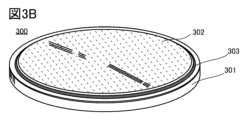
- FIG. 3B is a perspective view of the coin-type secondary battery
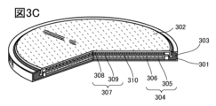
- FIG. 3C is a cross-sectional perspective view thereof.
- FIG. 4 is a diagram showing charge/discharge characteristics.
- FIG. 5 is a diagram showing cycle characteristics.
- FIG. 6A shows an example of a cylindrical secondary battery.
- FIG. 6B shows an example of a cylindrical secondary battery.
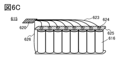
- FIG. 6C shows an example of a plurality of cylindrical secondary batteries.
- FIG. 14 is a cross-sectional view of the positive electrode active material.
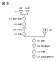
- FIG. 15 illustrates a method for producing a positive electrode active material.
- FIG. 16 is a graph showing the temperature rise of the secondary battery.
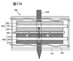
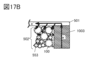
- FIGS. 17A and 17B are diagrams illustrating a nail penetration test.
- FIG. 18 is a graph showing the temperature rise of the secondary battery when an internal short circuit occurs.
- FIG. 19 is a diagram illustrating the crystal structure of the positive electrode active material.
- FIG. 20 is a diagram illustrating the crystal structure of a conventional positive electrode active material.
- FIG. 21 is a diagram showing an XRD pattern calculated from the crystal structure.
- FIG. 22 is a diagram showing an XRD pattern calculated from the crystal structure.
- a lithium ion secondary battery of one embodiment of the present invention will be described using as an example a secondary battery having a positive electrode, a negative electrode, and an electrolyte.
- a separator is provided between the positive electrode and the negative electrode.
- the separator may contain a liquid electrolyte (also referred to as an electrolytic solution). Note that when a solid electrolyte or a semi-solid electrolyte is used instead of the electrolytic solution, a separator is not required.
- it may have an exterior body that houses a positive electrode, a negative electrode, an electrolyte, and the like.
- the negative electrode active material layer is formed on one or both sides of the negative electrode current collector.
- the negative electrode active material layer is formed by applying a slurry onto a negative electrode current collector.
- the slurry is prepared by mixing carbon particles, silicon particles, and a binder, and adding water to the mixture.
- carbon particles graphite, carbon having a layered structure like graphite, amorphous carbon, and hard carbon can be used. Further, carbon fibers may be used instead of carbon particles.
- the carbon particles used in one embodiment of the present invention are specifically graphite particles. Graphite particles are preferable as the active material of the negative electrode because they are abundant in nature and are therefore inexpensive.
- the silicon particles have an average particle size of less than 1 ⁇ m and around 100 nm, and are sometimes referred to as nanosilicon particles.
- the silicon particles used are preferably adjusted to have a uniform particle size by pulverizing a silicon raw material.
- the silicon particles may include at least one of silicon, silicon oxide, and silicon alloy.
- the lithium ion secondary battery used as the silicon negative electrode active material can be a secondary battery with high energy density.
- silicon when only silicon is used as the negative electrode active material, there is a problem that rapid cycle deterioration occurs due to expansion and contraction during charging and discharging. In order to improve cycle deterioration, it is preferable to use micronized silicon.
- the average particle diameter of the graphite particles mixed with the silicon particles is preferably 1 ⁇ m or more, preferably 5 ⁇ m or more.
- the negative electrode active material includes both graphite particles and silicon particles. Since silicon particles are mixed and used for the negative electrode, a secondary battery with high energy density can be realized.
- the weight ratio in this specification is the compounding ratio when producing the electrode slurry described later, that is, the weight ratio (wt%) of the active material, conductive agent, and binder in the total weight (mixed powder). is pointing to. Therefore, the respective weight ratios after being made into a secondary battery may not match.
- the silicon weight ratio to the total weight of the powder material constituting the negative electrode active material is set to 7.5 wt% or more and 37.5 wt% or less. Furthermore, in the negative electrode active material layer, the weight ratio of silicon particles is made smaller than the weight ratio of graphite particles.
- the binder used for the negative electrode it is preferable to use a material having at least a polymer having a double bond of carbon and oxygen (ketone group).
- the oxygen in the ketone group has a lone pair of electrons, which may help lithium in the electrolyte to desolvate and enter the negative electrode active material.
- the binder used for the negative electrode it is preferable to use a material having at least a polymer having a carboxy group, and polyglutamic acid or polyacrylic acid is particularly preferable.
- Polar substituents on the polymer, including carboxy groups may help desolvate lithium in the electrolyte and enter the negative active material. Note that substituents such as carboxy groups can be analyzed by FT-IR or the like.
- a material in which polymers are crosslinked as a binder for the negative electrode since this allows a network structure to be formed within the negative electrode.
- the chemical formula of polyglutamic acid is shown below.
- the weight ratio of the binder is smaller than the weight ratio of the graphite particles. Further, if the weight ratio of the binder is too small, the effect will be reduced, so it is preferable to use the binder in an amount greater than 5 wt%.
- the silicon particles in the negative electrode so as not to oxidize them, and it is preferable to perform a mixing treatment so that the silicon particles are not oxidized when mixed with polyglutamic acid, graphite particles, and acetylene black.
- FIG. 2 shows an example of the manufacturing flow of the negative electrode active material layer of this embodiment.
- the slurry 106 is applied onto the negative electrode current collector 107. Then let it dry. After drying, press treatment is further performed. Heating may be performed simultaneously with the press treatment.
- the negative electrode 108 having the negative electrode active material layer on the negative electrode current collector 107 can be manufactured.
- the positive electrode active material 200 has a surface layer portion 200a and an interior portion 200b. In these figures, the boundary between the surface layer 200a and the interior 200b is indicated by a broken line.
- the surface layer portion 200a preferably contains an additive element, and more preferably contains a plurality of additive elements. Further, it is preferable that the concentration of one or more selected additive elements is higher in the surface layer portion 200a than in the interior portion 200b. Further, it is preferable that one or more selected from the additive elements included in the positive electrode active material 200 have a concentration gradient. Further, it is more preferable that the distribution of the positive electrode active material 200 differs depending on the added element. For example, it is more preferable that the depth of the detected amount peak in the surface layer from the surface or a reference point in EDX-ray analysis described below differs depending on the added element.
- FIG. 20 shows changes in the crystal structure of a conventional positive electrode active material.
- the conventional positive electrode active material shown in FIG. 20 is lithium cobalt oxide (LiCoO 2 ) that does not particularly contain magnesium.
- lithium occupies octahedral sites, and three CoO 2 layers exist in the unit cell. Therefore, this crystal structure is sometimes called an O3 type crystal structure.
- the CoO 2 layer refers to a structure in which an octahedral structure in which six oxygen atoms are coordinated with cobalt is continuous in a plane in a shared edge state. This is sometimes referred to as a layer consisting of an octahedron of cobalt and oxygen.
- the positive electrode active material has a crystal structure of trigonal space group P-3m1, and one CoO 2 layer is also present in the unit cell. Therefore, this crystal structure is sometimes called O1 type or trigonal O1 type.
- the trigonal crystal is sometimes converted into a complex hexagonal lattice and is called the hexagonal O1 type.
- ions such as cobalt and magnesium occupy six oxygen coordination positions. Note that a light element such as lithium may occupy the 4-coordination position of oxygen.
- the positive electrode active material 200 of one embodiment of the present invention changes in the crystal structure when x in Li x CoO 2 is small, that is, when a large amount of lithium is released, are suppressed more than in conventional positive electrode active materials. ing. In addition, changes in volume are also suppressed when comparing the same number of cobalt atoms. Therefore, the crystal structure of the positive electrode active material 200 does not easily collapse even after repeated charging and discharging such that x becomes 0.24 or less. Therefore, in the positive electrode active material 200, a decrease in charge/discharge capacity during charge/discharge cycles is suppressed.
- the positive electrode active material 200 has a large discharge capacity per weight and per volume. Therefore, by using the positive electrode active material 200, a lithium ion secondary battery with high discharge capacity per weight and per volume can be manufactured.
- a state in which x in Li x CoO 2 is small can be rephrased as a state in which the battery is charged at a high charging voltage.
- the positive electrode active material 200 of one embodiment of the present invention is preferable because it can maintain a crystal structure having R-3mO3 symmetry even when charged at a high charging voltage, for example, a voltage of 4.6 V or higher at 25°C. It can be rephrased. In addition, it can be said that it is preferable because an O3' type crystal structure can be obtained when charged at a higher charging voltage, for example, a voltage of 4.65 V or more and 4.7 V or less at 25° C.
- the voltage of the lithium ion secondary battery is lowered by the potential of graphite than the above.
- the potential of graphite is about 0.05V to 0.2V based on the potential of lithium metal. Therefore, in the case of a lithium ion secondary battery that uses graphite as the negative electrode active material, it has a similar crystal structure when the voltage obtained by subtracting the potential of graphite from the above voltage is applied.
- lithium is shown to exist at all lithium sites with equal probability, but the present invention is not limited to this. It may be concentrated in some lithium sites, or it may have a symmetry such as monoclinic O1 (Li 0.5 CoO 2 ) shown in FIG. 20, for example. The distribution of lithium can be analyzed, for example, by neutron diffraction.
- the concentration gradient of magnesium be the same at a plurality of locations in the surface layer portion 200a of the positive electrode active material 200.
- the reinforcement derived from magnesium exists homogeneously in the surface layer portion 200a. Even if part of the surface layer portion 200a is reinforced, if there is a portion without reinforcement, stress may be concentrated on the portion without reinforcement. When stress is concentrated on a portion of the positive electrode active material 200, defects such as cracks may occur there, leading to cracking of the positive electrode active material and a decrease in discharge capacity.
- magnesium does not necessarily have to have the same concentration gradient in all of the surface layer portions 200a of the positive electrode active material 200.
- cations are arranged parallel to the (001) plane.
- This can be said to be a structure in which two CoO layers and a lithium layer are alternately stacked parallel to the (001) plane. Therefore, the diffusion path of lithium ions also exists parallel to the (001) plane. Therefore, the (001) plane is called a basal plane, and the plane other than the (001) plane where the lithium ion diffusion path is exposed is called an edge plane.
- the (001) plane where the CoO 2 layer is present on the surface is relatively stable.
- the main diffusion path of lithium ions during charging and discharging is not exposed on the (001) plane.
- lithium ion diffusion paths are exposed on surfaces other than the (001) plane. Therefore, surfaces other than the (001) surface and the surface layer portion 200a having the surface are important regions for maintaining the diffusion path of lithium ions, and at the same time, they are unstable because they are the regions from which lithium ions first leave. Prone. Therefore, it is extremely important to reinforce the surface other than the (001) plane and the surface layer portion 200a having the plane in order to maintain the crystal structure of the entire positive electrode active material 200.
- Whether a certain positive electrode active material is the positive electrode active material 200 of one embodiment of the present invention having an O3' type crystal structure when x in Li x CoO 2 is small is determined by whether x in Li x CoO 2 is small. This can be determined by analyzing a positive electrode containing a positive electrode active material using XRD, electron beam diffraction, neutron beam diffraction, electron spin resonance (ESR), nuclear magnetic resonance (NMR), or the like.
- ESR electron spin resonance
- NMR nuclear magnetic resonance
- powder XRD is preferable because it provides a diffraction peak that reflects the crystal structure of the interior 200b of the cathode active material 200, which occupies most of the volume of the cathode active material 200.
- the crystal structure of the H1-3 type or trigonal O1 type changes. This may occur in some cases. Therefore, in order to determine whether the cathode active material 200 is one embodiment of the present invention, analysis of the crystal structure such as XRD, and information such as charging capacity or charging voltage are required.
- the positive electrode active material in a state where x is small may undergo a change in crystal structure when exposed to the atmosphere.
- the O3' type crystal structure may change to the H1-3 type crystal structure. Therefore, it is preferable that all samples subjected to crystal structure analysis be handled in an inert atmosphere such as an argon atmosphere.
- whether the distribution of additive elements in the positive electrode active material is in the state described above can be determined by, for example, XPS, energy dispersive X-ray spectroscopy (EDX), EPMA ( This can be determined by analysis using methods such as electronic probe microanalysis.
- the crystal structure of the surface layer portion 200a, grain boundaries, etc. can be analyzed by electron beam diffraction or the like of a cross section of the positive electrode active material 200.
- the positive electrode may be prepared by coating a positive electrode current collector made of aluminum foil with a slurry in which a positive electrode active material, a conductive material, and a binder are mixed.
- Lithium metal can be used for the counter electrode.
- LiPF 6 Lithium hexafluorophosphate
- EC ethylene carbonate
- DEC diethyl carbonate
- VC vinylene carbonate
- a polypropylene porous film with a thickness of 25 ⁇ m can be used as the separator.
- the positive electrode can and the negative electrode can may be made of stainless steel (SUS).
- the coin cell produced under the above conditions is charged at an arbitrary voltage (for example, 4.5V, 4.55V, 4.6V, 4.65V, 4.7V, 4.75V or 4.8V).
- the charging method is not particularly limited as long as it can be charged at any voltage for a sufficient amount of time.
- the current in CC charging can be 20 mA/g or more and 100 mA/g or less.
- CV charging can be completed at 2 mA/g or more and 10 mA/g or less.
- the temperature is 25°C.
- the coin cell After charging in this manner, the coin cell is disassembled in a glove box with an argon atmosphere and the positive electrode is taken out, thereby obtaining a positive electrode active material with an arbitrary charging capacity.
- XRD can be performed in a sealed container with an argon atmosphere.
- the conditions for charging and discharging the plurality of times may be different from the above-mentioned charging conditions.
- charging is performed by constant current charging at a current value of 20 mA/g or more and 100 mA/g or less to an arbitrary voltage (for example, 4.6 V, 4.65 V, 4.7 V, 4.75 V or 4.8 V), and then the current value is Constant voltage charging can be performed until the voltage is 2 mA/g or more and 10 mA/g or less, and discharging can be performed at a constant current of 2.5 V and 20 mA/g or more and 100 mA/g or less.
- constant current discharge can be performed at, for example, 2.5 V and a current value of 20 mA/g or more and 100 mA/g or less.
- XRD device Bruker AXS, D8 ADVANCE
- X-ray source Cu Output: 40kV, 40mA
- Divergence angle Div. Slit
- 0.5° Detector LynxEye Scan method: 2 ⁇ / ⁇ continuous scan Measurement range (2 ⁇ ): 15° or more and 90° or less Step width (2 ⁇ ): 0.01°
- Setting Counting time 1 second/step
- Sample table rotation 15 rpm
- a standard sample used for adjustment and calibration for example, a standard aluminum oxide sintered plate SRM 1976 from NIST (National Institute of Standards and Technology) can be used.
- the sample to be measured is a powder, it can be set by placing it on a glass sample holder or by sprinkling the sample on a greased silicone non-reflective plate.
- the positive electrode can be attached to the substrate with double-sided tape, and the positive electrode active material layer can be set according to the measurement surface required by the apparatus.
- a filter or the like may be used to make the characteristic X-rays monochromatic, or it may be performed using XRD data analysis software after obtaining an XRD pattern.
- XRD data analysis software For example, DEFFRAC.
- EVA XRD data analysis software manufactured by Bruker
- crystal structure analysis software used for fitting is not particularly limited, but for example, TOPASver. 3 (crystal structure analysis software manufactured by Bruker) can be used.
- FIGS. 21 and 22 show ideal powder XRD patterns (2 ⁇ (degree)) using the CuK ⁇ 1 ray, which are calculated from the models of the O3' type crystal structure and the H1-3 type crystal structure.
- the patterns of LiCoO 2 (O3) and CoO 2 (O1) were created using Reflex Powder, one of the modules of Materials Studio (BIOVIA), based on crystal structure information obtained from ICSD (Inorganic Crystal Structure Database).
- the XRD pattern of the H1-3 type crystal structure was created in the same manner as above based on the information on the H1-3 type crystal structure shown in FIG.
- the XRD pattern of the O3' type crystal structure was obtained by estimating the crystal structure from the XRD pattern of the positive electrode active material of one embodiment of the present invention, and using TOPAS ver. 3 (crystal structure analysis software manufactured by Bruker), and an XRD pattern was created in the same manner as the others.
- the positive electrode active material 200 of one embodiment of the present invention has an O3'-type crystal structure when x in Li x CoO 2 is small, it does not necessarily have to be an O3'-type crystal structure. It may contain other crystal structures, or may be partially amorphous. However, when Rietveld analysis is performed on the XRD pattern, the O3' type crystal structure is preferably 50% or more, more preferably 60% or more, and even more preferably 66% or more. If the O3' type crystal structure is 50% or more, more preferably 60% or more, even more preferably 66% or more, the positive electrode active material can have sufficiently excellent cycle characteristics.
- each diffraction peak after charging be sharp, that is, have a narrow half-width.
- the half width varies depending on the XRD measurement conditions or the 2 ⁇ value even for peaks generated from the same crystal phase.
- the half-width is preferably 0.2° or less, more preferably 0.15° or less, and 0.12° or less. More preferred.
- a narrower half-value width and higher crystallinity contribute to stabilization of the crystal structure after charging.
- conventional LiCoO 2 even if a part of the crystal structure resembles the O3' type crystal structure, the crystallite size becomes small and the peak becomes broad and small.
- XPS> With X-ray photoelectron spectroscopy (XPS), in the case of inorganic oxides, if monochromatic aluminum K ⁇ rays are used as the X-ray source, it is possible to analyze a region from the surface to a depth of about 2 to 8 nm (usually 5 nm or less). Therefore, it is possible to quantitatively analyze the concentration of each element in a region that is approximately half the depth of the surface layer 200a. Additionally, narrow scan analysis allows the bonding state of elements to be analyzed. Note that the quantitative accuracy of XPS is about ⁇ 1 atomic % in most cases, and the lower limit of detection is about 1 atomic %, although it depends on the element.
- the ratio Ni/Co of the number of atoms of nickel and cobalt, as determined by XPS analysis is preferably 0.05 or more, more preferably 0.06 or more, and even more preferably 0.07 or more. It is preferably 0.08 or more, and more preferably 0.09 or more. Further, Ni/Co is preferably 0.200 or less, preferably 0.150 or less, preferably 0.140 or less, preferably 0.130 or less, and 0.120 or less. It is preferably at most 0.110, or preferably at most 0.110.
- the ratio F/Co of the number of atoms of fluorine and cobalt, as determined by XPS analysis, is preferably 0.100 or more, more preferably 0.200 or more, and even more preferably 0.300 or more. It is preferably 0.400 or more, more preferably 0.500 or more, more preferably 0.600 or more, and even more preferably 0.700 or more. Further, F/Co is preferably 1.500 or less, preferably 1.200 or less, preferably 1.100 or less, preferably 1.000 or less, and 0.900 or less. It is preferable that it is below.
- the above range indicates that these additive elements are not attached to a narrow area on the surface of the positive electrode active material 200, but are widely distributed in the surface layer 200a of the positive electrode active material 200 at a preferable concentration. It can be said that it shows.
- the fact that it is in the above range means that even if x is repeatedly charged and discharged so that x becomes 0.24 or less, the crystal structure does not collapse easily, making it an excellent material. cycle characteristics can be achieved.
- the peak indicating the bond energy between fluorine and other elements is preferably 682 eV or more and less than 685 eV, and more preferably about 684.3 eV. This value is different from both the binding energy of lithium fluoride, 685 eV, and the binding energy of magnesium fluoride, 686 eV.
- the peak indicating the bond energy between magnesium and other elements is preferably 1302 eV or more and less than 1304 eV, and more preferably about 1303 eV. This value is different from the binding energy of magnesium fluoride, 1305 eV, and is close to the binding energy of magnesium oxide.
- ⁇ EDX> It is preferable that one or more selected from the additive elements included in the positive electrode active material 200 have a concentration gradient. Further, it is more preferable that the depth of the concentration peak from the surface of the positive electrode active material 200 differs depending on the added element.
- the concentration gradient of the additive element can be determined by, for example, exposing a cross section of the positive electrode active material 200 using FIB (Focused Ion Beam) or the like, and then using the cross section by energy dispersive X-ray spectroscopy (EDX) or EPMA (electronic electron beam). It can be evaluated by analysis using probe microanalysis).
- the positive electrode active material 200 of one embodiment of the present invention is subjected to EDX plane analysis or EDX point analysis, it can be confirmed that the concentration of each additive element, especially the additive element X, in the surface layer portion 200a is higher than that in the interior portion 200b.
- the transition metal M is 50% of the sum of the average value MAVE of the detected amount inside and the average value MBG of the background.
- oxygen become 50% of the sum of the average value O AVE of the internal detection amount and the average value O BG of the background is set as the reference point. Note that if the transition metal M and oxygen differ in the 50% point of the sum of the interior and background, this is considered to be due to the influence of oxygen-containing metal oxides, carbonates, etc. attached to the surface.
- a point that is 50% of the sum of the average value M AVE of the detected amount inside M and the average value M BG of the background can be adopted. Further, in the case of a positive electrode active material having a plurality of transition metals M, the reference point can be determined using M AVE and M BG of the elements having the largest number of counts in the interior 200b.
- the average value MBG of the cobalt background can be obtained by averaging the outer range of 2 nm or more, preferably 3 nm or more, avoiding the vicinity where the detected amount of cobalt starts to increase, for example.
- the average value MAVE of the internal detected amounts is 2 nm or more in a region where the cobalt and oxygen counts are saturated and stable, for example, at a depth of 30 nm or more, preferably 50 nm or more from the region where the detected amount of cobalt starts to increase. , preferably on average over a range of 3 nm or more.
- the average background value OBG of oxygen and the average value OAVE of the internal detected amount of oxygen can also be determined in the same manner.
- the surface of the positive electrode active material 200 in a cross-sectional STEM (scanning transmission electron microscope) image, etc. is the boundary between a region where an image derived from the crystal structure of the positive electrode active material is observed and a region where it is not observed. This is the outermost region in which an atomic column originating from the nucleus of a metal element with a higher atomic number than lithium among the metal elements constituting the substance is confirmed. Alternatively, it is the intersection of a tangent drawn to the brightness profile from the surface toward the bulk of the STEM image and the axis in the depth direction. Surfaces in STEM images and the like may be determined in conjunction with analysis with higher spatial resolution.
- the peak in STEM-EDX-ray analysis refers to the detection intensity in each element profile or the maximum value of characteristic X-rays for each element.
- noise in STEM-EDX-ray analysis may include a measured value of half-width that is less than the spatial resolution (R), for example, less than R/2.
- the magnesium concentration in the surface layer portion 200a is higher than the magnesium concentration in the interior portion 200b.
- the peak of the magnesium concentration in the surface layer 200a preferably exists within a depth of 3 nm from the surface of the positive electrode active material 200 toward the center, and more preferably exists within a depth of 1 nm.
- the magnesium concentration attenuates to 60% or less of the peak at a depth of 1 nm from the peak top. Further, it is preferable that the attenuation decreases to 30% or less of the peak at a depth of 2 nm from the peak top.
- the peak of concentration herein refers to the maximum value of concentration. Note that due to the influence of spatial resolution in EDX-ray analysis, the position where the magnesium concentration peak exists may take a negative value as the depth from the surface toward the inside.
- the distribution of fluorine preferably overlaps with the distribution of magnesium.
- the difference in the depth direction between the peak of fluorine concentration and the peak of magnesium concentration is preferably within 10 nm, more preferably within 3 nm, and even more preferably within 1 nm.
- the peak of fluorine concentration in the surface layer 200a preferably exists within a depth of 3 nm from the surface of the positive electrode active material 200 toward the center, and more preferably exists within a depth of 1 nm. Preferably, it is more preferable to exist at a depth of 0.5 nm. Alternatively, it is preferably within ⁇ 1 nm from the surface. Further, it is more preferable that the peak of the fluorine concentration be present slightly closer to the surface than the peak of the magnesium concentration, since this increases resistance to hydrofluoric acid. For example, the peak of fluorine concentration is more preferably 0.5 nm or more closer to the surface than the peak of magnesium concentration, and even more preferably 1.5 nm or more closer to the surface.
- the peak of nickel concentration in the surface layer 200a preferably exists within a depth of 3 nm from the surface of the positive electrode active material 200 toward the center, and preferably within a depth of 1 nm from the surface of the positive electrode active material 200 toward the center. It is more preferable that it exists, and even more preferably that it exists within a depth of 0.5 nm. Alternatively, it is preferably within ⁇ 1 nm from the surface.
- the distribution of nickel preferably overlaps with the distribution of magnesium.
- the difference in the depth direction between the peak of nickel concentration and the peak of magnesium concentration is preferably within 10 nm, more preferably within 3 nm, and even more preferably within 1 nm.
- the peak of the concentration of magnesium, nickel, or fluorine is closer to the surface than the peak of the aluminum concentration in the surface layer portion 200a when subjected to EDX-ray analysis.
- the peak of aluminum concentration preferably exists at a depth of 0.5 nm or more and 50 nm or less from the surface of the positive electrode active material 200 toward the center, and more preferably exists at a depth of 3 nm or more and 30 nm or less.
- the ratio of the number of atoms of magnesium Mg and cobalt Co (Mg/Co) at the peak of magnesium concentration is preferably 0.05 or more and 0.6 or less. , more preferably 0.1 or more and 0.4 or less.
- the ratio of the number of atoms of aluminum Al and cobalt Co (Al/Co) at the peak of the aluminum concentration is preferably 0.01 or more and 0.6 or less, more preferably 0.05 or more and 0.45 or less.
- the ratio of the number of atoms of nickel Ni and cobalt Co (Ni/Co) at the peak of nickel concentration is preferably 0 or more and 0.2 or less, more preferably 0.01 or more and 0.1 or less, and 0.05 or more and 0.1 or less. is more preferable.
- the ratio of the number of atoms of fluorine F and cobalt Co (F/Co) at the peak of the fluorine concentration is preferably 0 or more and 1.6 or less, more preferably 0.1 or more and 1.4 or less.
- the method of adding the additive elements is important.
- the melting point is lower than that of lithium cobalt oxide, it functions as a flux, and therefore, fluorine compounds such as lithium fluoride are suitable.
- fluorine compounds such as lithium fluoride are suitable.
- This heating may be called initial heating. Due to the initial heating, lithium is desorbed from a part of the surface layer 200a of lithium cobalt oxide, so that the distribution of the additive elements becomes even better.
- a method for manufacturing the positive electrode active material 200 through annealing and initial heating will be described with reference to FIG. 15.
- Step S11 a lithium source (Li source) and a cobalt source (Co source) are prepared as starting materials for lithium and cobalt, respectively.
- Li source Li source
- Co source cobalt source
- the lithium source it is preferable to use a compound containing lithium such as lithium carbonate, lithium hydroxide, lithium nitrate, or lithium fluoride, and as the cobalt source, it is preferable to use a compound containing cobalt, such as cobalt oxide, hydroxide, etc. Cobalt or the like can be used.
- Step S12 Next, the lithium source and the cobalt source are crushed and mixed to produce a mixed material (step S12). Grinding and mixing can be done dry or wet. It is preferable to use an aprotic solvent as the solvent in the wet method. A ball mill, a bead mill, or the like can be used as a means for crushing and mixing.
- Step S13 the mixed material is heated (step S13).
- the heating is preferably performed at a temperature of 800°C or higher and 1100°C or lower.
- the heating time is preferably 1 hour or more and 100 hours or less, and the temperature increase rate is preferably 80° C./h or more and 250° C./h or less. Heating is preferably carried out in an atmosphere containing less water and oxygen, such as dry air.
- Step S14 Through the above steps, lithium cobalt oxide (LiCoO 2 ) can be obtained (step S14).
- Step S15 Next, the composite oxide is heated (step S15). Since this step is the first heating of lithium cobalt oxide, the heating in step S15 is referred to as initial heating. After initial heating, the surface of lithium cobalt oxide becomes smooth. It has been found that deterioration after charging and discharging can be reduced by performing initial heating.
- lithium cobalt oxide with a smooth surface When lithium cobalt oxide with a smooth surface is used as a positive electrode active material, there is less deterioration during charging and discharging as a secondary battery, and cracking of the positive electrode active material can be prevented. Furthermore, it is possible to suppress combustion due to thermal runaway when a short circuit occurs such as in a nail penetration test.
- Additive element X may be added to lithium cobalt oxide having a smooth surface within a range that allows a layered rock salt type crystal structure (step S20). When the additive element X is added to lithium cobalt oxide having a smooth surface, the additive element can be added evenly. Additive elements One or more selected from bromine and beryllium can be used. Note that as the additive element X, magnesium and fluorine are preferable, and it is preferable to use lithium fluoride as the fluorine source and magnesium fluoride as the magnesium source. An additive element source (X source) can be produced by crushing and heating the additive element X in the same manner as in S12 and S13.
- the particle size of the additive element source is preferably such that the median diameter (D50) is 600 nm or more and 20 ⁇ m or less, because this facilitates the uniform adhesion of the mixture to the surface layer of the composite oxide particles.
- the inclusion of fluorine and magnesium in the surface layer facilitates the formation of O3' type and O3'' type crystal structures in the charged state.
- Step S31 lithium cobalt oxide and an additive element source (X source) are mixed (step S31).
- the ratio between Co, the number of atoms of transition metal in the composite oxide containing lithium, transition metal, and oxygen, and Mg, the number of atoms of magnesium in the X source, is Co:Mg 100:y (0.1 ⁇ y ⁇ 6 ) is preferable.
- Step S32> Next, the materials mixed above are collected to obtain a mixture 903 (step S32).
- Step S33 Next, the mixture 903 is heated (step S33).
- the heating conditions can be selected from the heating conditions explained in step S13.
- the heating temperature is preferably 500°C or more and 1130°C or less, and the heating time is preferably 2 hours or more.
- Step S34 Next, the heated material is collected and crushed if necessary to obtain the positive electrode active material 200 (step S34). At this time, it is preferable to further sieve the collected particles. Through the above steps, the positive electrode active material 200 can be manufactured.
- the positive electrode has a positive electrode active material layer and a positive electrode current collector.
- the positive electrode active material layer includes the positive electrode active material 200 described above, and may also include a conductive material (synonymous with a conductive additive) and a binder.
- carbon-based materials such as acetylene black can be used.
- carbon nanotubes, graphene, or graphene compounds can be used as the conductive material.
- binder examples include styrene-butadiene rubber (SBR), styrene-isoprene-styrene rubber, acrylonitrile-butadiene rubber, butadiene rubber, ethylene-propylene-diene copolymer, fluororubber, carboxymethylcellulose (CMC), methylcellulose, and ethylcellulose.
- SBR styrene-butadiene rubber
- CMC carboxymethylcellulose
- methylcellulose methylcellulose
- ethylcellulose ethylcellulose
- cellulose derivatives such as hydroxypropyl cellulose, diacetyl cellulose, and regenerated cellulose, starch, polystyrene, polyglutamic acid, polymethyl acrylate, polymethyl methacrylate (polymethyl methacrylate, PMMA), sodium polyacrylate, polyvinyl alcohol (PVA), Polyethylene oxide (PEO), polypropylene oxide, polyimide, polyvinyl chloride, polytetrafluoroethylene, polyethylene, polypropylene, polyisobutylene, polyethylene terephthalate, nylon, polyvinylidene fluoride (PVDF), polyacrylonitrile (PAN), ethylene propylene diene polymer, It is preferable to use materials such as polyvinyl acetate and nitrocellulose.
- the binder may be used in combination of two or more of the above binders.
- the current collector highly conductive materials such as metals such as stainless steel, gold, platinum, aluminum, and titanium, and alloys thereof can be used. Further, it is preferable that the material used for the positive electrode current collector does not elute at the potential of the positive electrode. Furthermore, an aluminum alloy to which an element that improves heat resistance, such as silicon, titanium, neodymium, scandium, or molybdenum is added, can be used. Alternatively, it may be formed of a metal element that reacts with silicon to form silicide.
- metal elements that react with silicon to form silicide include zirconium, titanium, hafnium, vanadium, niobium, tantalum, chromium, molybdenum, tungsten, cobalt, and nickel.
- the current collector may have a foil shape, a plate shape, a sheet shape, a net shape, a punched metal shape, an expanded metal shape, or the like as appropriate.
- the current collector preferably has a thickness of 5 ⁇ m or more and 30 ⁇ m or less.
- the electrolytic solution includes a solvent and an electrolyte. It is preferable to use an ionic liquid (room temperature molten salt) that is flame retardant and hardly volatile. By using one or more of these strands, even if the internal temperature of the secondary battery increases due to an internal short circuit or overcharging, it is possible to prevent the secondary battery from bursting and/or catching fire.
- Ionic liquids are composed of cations and anions, and include organic cations and anions.
- Examples of the organic cation used in the electrolytic solution include aliphatic onium cations such as quaternary ammonium cations, tertiary sulfonium cations, and quaternary phosphonium cations, and aromatic cations such as imidazolium cations and pyridinium cations.
- examples of anions used in the electrolytic solution include monovalent amide anions, monovalent methide anions, fluorosulfonic acid anions, perfluoroalkylsulfonic acid anions, tetrafluoroborate anions, perfluoroalkylborate anions, and hexafluorophosphate anions. , or perfluoroalkyl phosphate anion.
- an aprotic organic solvent can be used as a solvent for the electrolytic solution.
- the aprotic organic solvent include ethylene carbonate (EC), propylene carbonate (PC), butylene carbonate, chloroethylene carbonate, vinylene carbonate, ⁇ -butyrolactone, ⁇ -valerolactone, dimethyl carbonate (DMC), diethyl carbonate (DEC), ethyl methyl carbonate (EMC), methyl formate, methyl acetate, ethyl acetate, methyl propionate, ethyl propionate, propyl propionate, methyl butyrate, 1,3-dioxane, 1,4-dioxane, dimethoxyethane (DME), dimethyl sulfoxide, diethyl ether, methyl diglyme, acetonitrile, benzonitrile, tetrahydrofuran, sulfolane, sultone, etc., or two or
- fluorinated cyclic carbonate sometimes referred to as fluorinated cyclic carbonate
- fluorinated linear carbonate sometimes referred to as fluorinated chain carbonate
- fluorinated cyclic carbonate for example, fluoroethylene carbonate (fluoroethylene carbonate, FEC, F1EC), difluoroethylene carbonate (DFEC, F2EC), trifluoroethylene carbonate (F3EC), or tetrafluoroethylene carbonate (F4EC) is used. be able to.
- DFEC has isomers such as cis-4,5 and trans-4,5.
- any of the fluorinated cyclic carbonates has a substituent that exhibits electron-withdrawing properties, it is thought that the solvation energy of lithium ions is low.
- the fluorinated chain carbonate include methyl 3,3,3-trifluoropropionate, trifluoromethyl 3,3,3-trifluoropropionate, trifluoromethyl propionate, methyl 2,2-difluoropropionate, etc. can be mentioned.
- the fluorinated chain carbonate has the effect of lowering or maintaining the viscosity of the electrolytic solution. Therefore, if the mixed solvent contains a fluorinated cyclic carbonate and a fluorinated chain carbonate, a lithium ion secondary battery that can be charged and discharged in a low temperature environment can be provided.
- electrolytes to be dissolved in the above solvent examples include LiPF 6 , LiClO 4 , LiAsF 6 , LiBF 4 , LiAlCl 4 , LiSCN, LiBr, LiI, Li 2 SO 4 , Li 2 B 10 Cl1 0, Li 2 B1 2Cl12 , LiCF3SO3 , LiC4F9SO3 , LiC (CF3SO2 ) 3 , LiC ( C2F5SO2 ) 3 , LiN ( CF3SO2 ) 2 , LiN( C4F
- One type of lithium salt such as 9 SO 2 ) (CF 3 SO 2 ), LiN (C 2 F 5 SO 2 ) 2 or two or more of these can be used in any combination and ratio.
- the electrolyte includes vinylene carbonate, propane sultone (PS), tert-butylbenzene (TBB), fluoroethylene carbonate (FEC), lithium bis(oxalate) borate (LiBOB), and dinitrile compounds such as succinonitrile and adiponitrile.
- Additives may also be added.
- the concentration of the added material may be, for example, 0.1 wt% or more and 5 wt% or less based on the entire solvent.
- VC or LiBOB is particularly preferable because it easily forms a good coating.
- a polymer gel electrolyte in which a polymer is swollen with an electrolytic solution may be used.
- silicone gel acrylic gel, acrylonitrile gel, polyethylene oxide gel, polypropylene oxide gel, fluoropolymer gel, etc. can be used.
- polymers having a polyalkylene oxide structure such as polyethylene oxide (PEO), PVDF, polyacrylonitrile, and copolymers containing them can be used.
- PVDF-HFP which is a copolymer of PVDF and hexafluoropropylene (HFP)
- the polymer formed may also have a porous shape.
- a solid electrolyte having an inorganic material such as a sulfide-based or oxide-based material, a solid electrolyte having a polymeric material such as a PEO (polyethylene oxide)-based material, etc. can be used.
- a solid electrolyte it is not necessary to install a separator and/or spacer. Additionally, since the entire battery can be solidified, there is no risk of leakage, dramatically improving safety.
- the secondary battery has a separator.
- the separator may be made of, for example, paper, nonwoven fabric, glass fiber, ceramics, or synthetic fibers using nylon (polyamide), vinylon (polyvinyl alcohol fiber), polyester resin, acrylic resin, polyolefin resin, polyurethane resin, etc. can be used. It is preferable that the separator is processed into an envelope shape and arranged so as to surround either the positive electrode or the negative electrode.
- the separator may have a multilayer structure.
- a film of an organic material such as polypropylene or polyethylene can be coated with a ceramic material, a fluorine material, a polyamide material, or a mixture thereof.
- the ceramic material for example, aluminum oxide particles, silicon oxide particles, etc. can be used.
- the fluorine-based material for example, PVDF, polytetrafluoroethylene, etc. can be used.
- the polyamide material for example, nylon, aramid (meta-aramid, para-aramid), polyimide, etc. can be used.
- Coating with a ceramic material improves oxidation resistance, so it is possible to suppress deterioration of the separator during high voltage charging and discharging and improve the reliability of the secondary battery. Furthermore, coating with a fluorine-based material makes it easier for the separator and electrode to come into close contact with each other, thereby improving output characteristics. Coating with a polyamide-based material, especially aramid, improves heat resistance, thereby improving the safety of the secondary battery.
- a mixed material of aluminum oxide and aramid may be coated on both sides of a polypropylene film.
- the surface of the polypropylene film in contact with the positive electrode may be coated with a mixed material of aluminum oxide and aramid, and the surface in contact with the negative electrode may be coated with a fluorine-based material.
- the safety of the secondary battery can be maintained even if the overall thickness of the separator is thin, so the discharge capacity per volume of the secondary battery can be increased.
- a metal material such as aluminum and/or a resin material can be used, for example.
- a film-like exterior body can also be used.
- a film for example, a highly flexible metal thin film such as aluminum, stainless steel, copper, or nickel is provided on a film made of a material such as polyethylene, polypropylene, polycarbonate, ionomer, or polyamide, and an exterior coating is further applied on the metal thin film.
- a three-layered film having an insulating synthetic resin film such as polyamide resin or polyester resin can be used as the outer surface of the body.
- Sample 1 had a weight ratio of silicon particles, graphite particles, polyglutamic acid, and acetylene black of 8:72:14:6.
- silicon particles silicon particles (manufactured by Aldrich, product number 633097) having a specific surface area of 12.7715 m 2 /g and a particle diameter of 100 nm by the BET method were used.
- graphite particles graphite (Formula BT 1520, manufactured by Superior Graphite) with an average particle diameter of 20 ⁇ m was used.
- Polyglutamic acid manufactured by Nippon Polyglu Co., Ltd.
- Polyglutamic acid also called PGA was used without neutralization.
- the negative electrode is made by mixing graphite particles, silicon particles, a binder, and acetylene black in predetermined amounts, adding deionized water to create a slurry, coating it on a current collector (copper foil), drying it, and pressing it. It was created by doing.
- Polyglutamic acid is a polar polymer and has hydrophilic properties, so it can be dissolved in deionized water.
- a half cell sample 1 was prepared using a negative electrode coated on a current collector. Note that after coating, sufficient heating was performed to evaporate the solvent component (water). The amount of negative electrode supported was adjusted to be in the range of 3.8 mg/cm 2 or more and 4.2 mg/cm 2 or less.
- a positive electrode can and a negative electrode can made of stainless steel (SUS) were used, lithium metal was prepared as a counter electrode, and a coin-shaped half cell using the above negative electrode configuration was fabricated.
- the separator used was PP (porous polypropylene), and the electrolyte was EMI-FSI (1-ethyl-3-methylimidazolium bis(fluorosulfonyl)imide) in which 2.15M LiFSI was dissolved as an ionic liquid. Using. The cation of the ionic liquid, EMI, does not have fluorine at its end. The concentration of lithium salt in the electrolytic solution was 2.15 mol/L.
- the charge/discharge curve shown in FIG. 4 shows that a half cell used as a negative electrode is discharged at a predetermined current from 1V to 0.01V at a discharge rate of 0.1C at room temperature, and when it reaches 0.01V, it is switched to a constant voltage and discharged. (first discharge). Thereafter, the battery was charged at a first charge rate of 0.1C until the voltage reached 1V (first charge). This is called one cycle. Thereafter, a rest period of 1 hour was provided, and the second discharge was performed at a discharge rate of 0.2 C, and then discharged at a predetermined current. Thereafter, the battery was charged at a second charging rate of 0.2C until the voltage reached 1V.
- sample 1 was subjected to a cycle test up to 50 cycles, and the results are shown in FIG.
- the first and second breaks were 1 hour.
- the second and third breaks were 10 minutes.
- the rest period from the third time onwards was 10 minutes.
- a cycle test was conducted with the charge rate for the third and subsequent times set at 0.2C and the discharge rate set at 0.2C.
- FIG. 5 also shows the cycle characteristics of Sample 2, which had the same structure as Sample 1 except that polyglutamic acid was 18 wt%. Measurements were performed in the same manner as for sample 1.
- sample 2 the weight ratio of silicon particles, graphite particles, polyglutamic acid, and acetylene black was 7.6:68.4:18:6.
- the initial charge amount of Sample 2 was 591.7 mAh/g. Although sample 1 has a higher initial charge amount, it can be seen that the cycle maintenance rate of sample 2 is better than that of sample 1.
- Embodiment 2 In this embodiment, an example of the shape of a secondary battery having the positive electrode and the negative electrode described in Embodiment 1 will be described.
- FIG. 3A is an exploded perspective view of a coin-shaped (single-layer flat type) secondary battery
- FIG. 3B is an external view
- FIG. 3C is a cross-sectional view thereof.
- Coin-shaped secondary batteries are mainly used in small electronic devices.
- FIG. 3A is a schematic diagram so that the overlapping (vertical relationship and positional relationship) of members can be seen. Therefore, FIGS. 3A and 3B are not completely corresponding diagrams.
- a positive electrode 304, a separator 310, a negative electrode 307, a spacer 322, and a washer 312 are stacked. These are sealed with a negative electrode can 302 and a positive electrode can 301 with a gasket. Note that in FIG. 3A, a gasket for sealing is not shown.
- the spacer 322 and the washer 312 are used to protect the inside or fix the position inside the can when the positive electrode can 301 and the negative electrode can 302 are crimped together.
- the spacer 322 and washer 312 are made of stainless steel or an insulating material.
- a positive electrode 304 has a laminated structure in which a positive electrode active material layer 306 is formed on a positive electrode current collector 305 .
- FIG. 3B is a perspective view of the completed coin-shaped secondary battery.
- a positive electrode can 301 that also serves as a positive electrode terminal and a negative electrode can 302 that also serves as a negative electrode terminal are insulated and sealed with a gasket 303 made of polypropylene.
- the positive electrode 304 is formed by a positive electrode current collector 305 and a positive electrode active material layer 306 provided in contact with the positive electrode current collector 305 .
- the negative electrode 307 is formed of a negative electrode current collector 308 and a negative electrode active material layer 309 provided in contact with the negative electrode current collector 308. Further, the negative electrode 307 is not limited to a laminated structure, and lithium metal foil or lithium-aluminum alloy foil may be used.
- the positive electrode 304 and the negative electrode 307 used in the coin-shaped secondary battery 300 may each have an active material layer formed only on one side.
- the positive electrode can 301 and the negative electrode can 302 metals such as nickel, aluminum, and titanium, which are corrosion resistant to electrolyte, or alloys thereof, or alloys of these and other metals (for example, stainless steel) can be used. Further, in order to prevent corrosion caused by electrolyte, it is preferable to coat with nickel or aluminum.
- the positive electrode can 301 is electrically connected to the positive electrode 304, and the negative electrode can 302 is electrically connected to the negative electrode 307.
- negative electrode 307, positive electrode 304, and separator 310 are immersed in an electrolytic solution or an ionic liquid, and the positive electrode 304, separator 310, negative electrode 307, and negative electrode can 302 are stacked in this order with the positive electrode can 301 facing down, as shown in FIG. 3C. , a positive electrode can 301 and a negative electrode can 302 are crimped together via a gasket 303 to produce a coin-shaped secondary battery 300.
- separator 310 for example, fibers containing cellulose such as paper, nonwoven fabrics, glass fibers, ceramics, nylon resin (polyamide), vinylon resin (polyvinyl alcohol fiber), polyester resin, acrylic resin, polyolefin resin, polyurethane are used. A material made of synthetic fiber using resin can be used.
- the separator may have a multilayer structure.
- a film of an organic material such as polypropylene or polyethylene can be coated with a ceramic material, a fluorine material, a polyamide material, or a mixture thereof.
- the ceramic material for example, aluminum oxide particles, silicon oxide particles, etc. can be used.
- the fluorine-based material for example, PVDF, polytetrafluoroethylene, etc. can be used.
- the polyamide material for example, nylon, aramid (meta-aramid, para-aramid), etc. can be used.
- Coating with a ceramic material improves oxidation resistance, so it is possible to suppress deterioration of the separator during high voltage charging and discharging and improve the reliability of the secondary battery. Furthermore, coating with a fluorine-based material makes it easier for the separator and electrode to come into close contact with each other, thereby improving output characteristics. Coating with a polyamide-based material, especially aramid, improves heat resistance, thereby improving the safety of the secondary battery.
- a mixed material of aluminum oxide and aramid may be coated on both sides of a polypropylene film.
- the surface of the polypropylene film in contact with the positive electrode may be coated with a mixed material of aluminum oxide and aramid, and the surface in contact with the negative electrode may be coated with a fluorine-based material.
- the safety of the secondary battery can be maintained even if the overall thickness of the separator is thin, so the capacity per volume of the secondary battery can be increased.
- a coin-shaped secondary battery 300 may be used.
- the cylindrical secondary battery 616 has a positive electrode cap (battery lid) 601 on the top surface and a battery can (exterior can) 602 on the side and bottom surfaces. These positive electrode cap 601 and battery can (exterior can) 602 are insulated by a gasket (insulating packing) 610.
- FIG. 6B is a diagram schematically showing a cross section of a cylindrical secondary battery.
- the cylindrical secondary battery shown in FIG. 6B has a positive electrode cap (battery lid) 601 on the top surface and a battery can (exterior can) 602 on the side and bottom surfaces.
- These positive electrode caps and the battery can (exterior can) 602 are insulated by a gasket (insulating packing) 610.
- a secondary battery is provided inside the hollow cylindrical battery can 602, in which a band-shaped positive electrode 604 and a negative electrode 606 are wound with a separator 605 in between.
- the secondary battery is wound around a central axis.
- the battery can 602 has one end closed and the other end open.
- metals such as nickel, aluminum, and titanium, which are corrosion resistant to electrolyte, or alloys thereof, or alloys of these and other metals (for example, stainless steel) can be used. Further, in order to prevent corrosion caused by the electrolyte, it is preferable to coat the battery can 602 with nickel and aluminum.
- a secondary battery in which a positive electrode, a negative electrode, and a separator are wound is sandwiched between a pair of opposing insulating plates 608 and 609. Furthermore, a non-aqueous electrolyte (not shown) is injected into the inside of the battery can 602 in which the secondary battery is provided.
- the non-aqueous electrolyte the same one as a coin-type secondary battery can be used.
- the positive electrode and negative electrode used in a cylindrical storage battery are wound, it is preferable to form an active material on both sides of the current collector.
- the battery has excellent cycle characteristics and excellent safety and reliability.
- the secondary battery 616 can have a cylindrical shape.
- a positive electrode terminal (positive electrode current collector lead) 603 is connected to the positive electrode 604, and a negative electrode terminal (negative electrode current collector lead) 607 is connected to the negative electrode 606.
- Both the positive electrode terminal 603 and the negative electrode terminal 607 can be made of a metal material such as aluminum.
- the positive terminal 603 and the negative terminal 607 are resistance welded to the safety valve mechanism 613 and the bottom of the battery can 602, respectively.
- the safety valve mechanism 613 is electrically connected to the positive electrode cap 601 via a PTC element (Positive Temperature Coefficient) 611. The safety valve mechanism 613 disconnects the electrical connection between the positive electrode cap 601 and the positive electrode 604 when the increase in the internal pressure of the battery exceeds a predetermined threshold value.
- the PTC element 611 is a heat-sensitive resistance element whose resistance increases when the temperature rises, and the increase in resistance limits the amount of current to prevent abnormal heat generation.
- Barium titanate (BaTiO 3 )-based semiconductor ceramics can be used for the PTC element.
- FIG. 6C shows an example of the power storage system 615.
- Power storage system 615 includes a plurality of secondary batteries 616.
- the positive electrode of each secondary battery contacts a conductor 624 separated by an insulator 625 and is electrically connected.
- the conductor 624 is electrically connected to the control circuit 620 via the wiring 623.
- the negative electrode of each secondary battery is electrically connected to the control circuit 620 via a wiring 626.
- As the control circuit 620 a charge/discharge control circuit or a protection circuit that prevents overcharging and/or overdischarging can be applied.
- FIG. 6D shows an example of the power storage system 615.
- the power storage system 615 includes a plurality of secondary batteries 616, and the plurality of secondary batteries 616 are sandwiched between a conductive plate 628 and a conductive plate 614.
- the plurality of secondary batteries 616 are electrically connected to a conductive plate 628 and a conductive plate 614 by wiring 627.
- the plurality of secondary batteries 616 may be connected in parallel, connected in series, or connected in parallel and then further connected in series.
- the plurality of secondary batteries 616 may be connected in parallel and then further connected in series.
- a temperature control device may be provided between the plurality of secondary batteries 616.
- the secondary battery 616 When the secondary battery 616 is overheated, it can be cooled by the temperature control device, and when the secondary battery 616 is too cold, it can be heated by the temperature control device. Therefore, the performance of power storage system 615 is less affected by outside temperature.
- the power storage system 615 is electrically connected to the control circuit 620 via wiring 621 and wiring 622.
- the wiring 621 is electrically connected to the positive electrodes of the plurality of secondary batteries 616 via the conductive plate 628
- the wiring 622 is electrically connected to the negative electrodes of the plurality of secondary batteries 616 via the conductive plate 614.
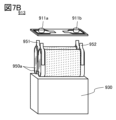
- a secondary battery 913 having a wound body 950a as shown in FIG. 7A may be used.
- a wound body 950a shown in FIG. 7A includes a negative electrode 931, a positive electrode 932, and a separator 933.
- the negative electrode 931 has a negative electrode active material layer 931a.
- the positive electrode 932 has a positive electrode active material layer 932a.
- the separator 933 has a width wider than the negative electrode active material layer 931a and the positive electrode active material layer 932a, and is wound so as to overlap with the negative electrode active material layer 931a and the positive electrode active material layer 932a. Further, from the viewpoint of safety, it is preferable that the width of the negative electrode active material layer 931a is wider than that of the positive electrode active material layer 932a. Further, the wound body 950a having such a shape is preferable because it has good safety and productivity.
- the separator 933 has a width wider than the negative electrode active material layer 931a and the positive electrode active material layer 932a, and is wound so as to overlap with the negative electrode active material layer 931a and the positive electrode active material layer 932a. Further, from the viewpoint of safety, it is preferable that the width of the negative electrode active material layer 931a is wider than that of the positive electrode active material layer 932a. Further, the wound body 950a having such a shape is preferable because it has good safety and productivity.
- the negative electrode 931 is electrically connected to the terminal 951 by ultrasonic bonding, welding, or crimping.
- Terminal 951 is electrically connected to terminal 911a.
- the positive electrode 932 is electrically connected to the terminal 952 by ultrasonic bonding, welding, or crimping.
- Terminal 952 is electrically connected to terminal 911b.
- the housing 930 covers the wound body 950a and the electrolytic solution, forming a secondary battery 913. It is preferable that the housing 930 be provided with a safety valve and an overcurrent protection element.
- a metal material for example, aluminum
- a resin material can be used as the housing 930.
- the safety valve is a valve that opens the inside of the casing 930 at a predetermined internal pressure in order to prevent the battery from exploding.
- the secondary battery 913 may have a plurality of wound bodies 950a. By using a plurality of wound bodies 950a, the secondary battery 913 can have a larger discharge capacity.
- FIGS. 8A and 8B an example of an external view of an example of a laminated secondary battery is shown in FIGS. 8A and 8B.
- 8A and 8B have a positive electrode 503, a negative electrode 506, a separator 507, an exterior body 509, a positive lead electrode 510, and a negative lead electrode 511.
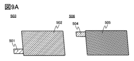
- FIG. 9A shows an external view of the positive electrode 503 and the negative electrode 506.
- the positive electrode 503 has a positive electrode current collector 501 , and the positive electrode active material layer 502 is formed on the surface of the positive electrode current collector 501 . Further, the positive electrode 503 has a region (hereinafter referred to as a tab region) where the positive electrode current collector 501 is partially exposed.
- the negative electrode 506 has a negative electrode current collector 504 , and the negative electrode active material layer 505 is formed on the surface of the negative electrode current collector 504 . Further, the negative electrode 506 has a region where the negative electrode current collector 504 is partially exposed, that is, a tab region. Note that the area or shape of the tab regions of the positive electrode and the negative electrode is not limited to the example shown in FIG. 9A.
- FIG. 9B shows a stacked negative electrode 506, separator 507, and positive electrode 503.
- an example is shown in which five sets of negative electrodes and four sets of positive electrodes are used. It can also be called a laminate consisting of a negative electrode, a separator, and a positive electrode.
- the tab regions of the positive electrodes 503 are joined together, and the positive lead electrode 510 is joined to the tab region of the outermost positive electrode. For example, ultrasonic welding may be used for joining.
- the tab regions of the negative electrodes 506 are bonded to each other, and the negative lead electrode 511 is bonded to the tab region of the outermost negative electrode.
- a negative electrode 506, a separator 507, and a positive electrode 503 are placed on the exterior body 509.
- the exterior body 509 is bent at the portion indicated by the broken line. After that, the outer peripheral portion of the exterior body 509 is joined. For example, thermocompression bonding may be used for bonding. At this time, a region (hereinafter referred to as an inlet) that is not joined is provided in a part (or one side) of the exterior body 509 so that the electrolyte can be introduced later.
- an inlet a region (hereinafter referred to as an inlet) that is not joined is provided in a part (or one side) of the exterior body 509 so that the electrolyte can be introduced later.
- the electrolytic solution is introduced into the interior of the exterior body 509 through an inlet provided in the exterior body 509 .
- the electrolytic solution is preferably introduced under a reduced pressure atmosphere or an inert atmosphere. Finally, connect the inlet. In this way, a laminate type secondary battery 500 can be manufactured.
- a secondary battery with excellent cycle characteristics, safety, and reliability can be obtained. It can be a battery 500.
- a plurality of secondary batteries shown in any one of FIG. 6A, FIG. 7C, FIG. 8A, and FIG. 8B are installed in a vehicle, it becomes a hybrid vehicle (HV), an electric vehicle (EV), or a plug-in hybrid vehicle (PHV).
- HV hybrid vehicle
- EV electric vehicle
- PHS plug-in hybrid vehicle
- next-generation clean energy vehicles such as
- agricultural machinery, motorized bicycles including electrically assisted bicycles, motorcycles, electric wheelchairs, electric carts, small or large ships, submarines, aircraft such as fixed-wing aircraft and rotary-wing aircraft, rockets, artificial satellites, space probes, Rechargeable batteries can also be installed in transportation vehicles for planetary probes and spacecraft.
- the secondary battery of one embodiment of the present invention can be a high capacity secondary battery. Therefore, the lithium ion secondary battery of one embodiment of the present invention is suitable for downsizing and weight reduction, has excellent safety and reliability, and can be suitably used for transportation vehicles.
- a car 2001 shown in FIG. 10A is an electric car that uses an electric motor as a power source for driving. Alternatively, it is a hybrid vehicle that can appropriately select and use an electric motor and an engine as a power source for driving.
- a secondary battery is mounted on a vehicle, the example of the secondary battery shown in Embodiment 3 is installed at one location or multiple locations.
- An automobile 2001 shown in FIG. 10A includes a battery pack 2200, and the battery pack includes a secondary battery module to which a plurality of secondary batteries are connected. Furthermore, it is preferable to include a charging control device electrically connected to the secondary battery module.
- the automobile 2001 can be charged by receiving power from an external charging facility using a plug-in method, a non-contact power supply method, or the like to a secondary battery of the automobile 2001.
- a predetermined charging method and connector standard such as CHAdeMO (registered trademark) or combo may be used as appropriate.
- the charging equipment may be a charging station provided at a commercial facility or may be a home power source.
- plug-in technology it is possible to charge the power storage device mounted on the vehicle 2001 by supplying power from the outside. Charging can be performed by converting AC power into DC power via a conversion device such as an ACDC converter.
- a power receiving device can be mounted on a vehicle and electrical power can be supplied from a ground power transmitting device in a non-contact manner for charging.
- this non-contact power supply method by incorporating a power transmission device into the road or outside wall, charging can be performed not only while the vehicle is stopped but also while the vehicle is running. Further, electric power may be transmitted and received between two vehicles using this contactless power supply method.
- a solar cell may be provided on the exterior of the vehicle to charge the secondary battery when the vehicle is stopped and when the vehicle is running.
- an electromagnetic induction method or a magnetic resonance method can be used.
- FIG. 10B shows a large transport vehicle 2002 having an electrically controlled motor as an example of a transport vehicle.
- the secondary battery module of the transport vehicle 2002 has a maximum voltage of 170V, for example, in which four secondary batteries with a nominal voltage of 3.0 V or more and 5.0 V or less are connected in series, and 48 cells are connected in series. Except for the difference in the number of secondary batteries constituting the secondary battery module of the battery pack 2201, it has the same functions as those in FIG. 10A, so a description thereof will be omitted.
- FIG. 10C shows, by way of example, a large transport vehicle 2003 with an electrically controlled motor.
- the secondary battery module of the transportation vehicle 2003 has a maximum voltage of 600 V, for example, by connecting in series one hundred or more secondary batteries with a nominal voltage of 3.0 V or more and 5.0 V or less.
- a secondary battery using the positive electrode and negative electrode described in Embodiment 1 a secondary battery with good rate characteristics and charge/discharge cycle characteristics, and excellent safety and reliability can be manufactured. , can contribute to higher performance and longer life of the transport vehicle 2003. Further, since it has the same functions as those in FIG. 10A except for the difference in the number of secondary batteries that constitute the secondary battery module of the battery pack 2202, a description thereof will be omitted.
- FIG. 10D shows an example aircraft 2004 with an engine that burns fuel. Since the aircraft 2004 shown in FIG. 10D has wheels for takeoff and landing, it can be said to be part of a transportation vehicle, and a secondary battery module is configured by connecting a plurality of secondary batteries, and the aircraft 2004 is connected to a secondary battery module and charged.
- the battery pack 2203 includes a control device.
- the secondary battery module of the aircraft 2004 has a maximum voltage of 32V, for example, by connecting eight 4V secondary batteries in series. Except for the difference in the number of secondary batteries constituting the secondary battery module of the battery pack 2203, it has the same functions as those in FIG. 10A, so a description thereof will be omitted.
- the house shown in FIG. 11A includes a power storage device 2612 including a secondary battery, which is one embodiment of the present invention, and a solar panel 2610.
- Power storage device 2612 is electrically connected to solar panel 2610 via wiring 2611 and the like. Further, the power storage device 2612 and the ground-mounted charging device 2604 may be electrically connected. Electric power obtained by the solar panel 2610 can charge the power storage device 2612. Further, the power stored in the power storage device 2612 can be charged to a secondary battery included in the vehicle 2603 via the charging device 2604.
- the power storage device 2612 is preferably installed in the underfloor space. By installing it in the underfloor space, the space above the floor can be used effectively. Alternatively, power storage device 2612 may be installed on the floor.
- the power stored in the power storage device 2612 can also be supplied to other electronic devices in the house. Therefore, even when power cannot be supplied from a commercial power source due to a power outage, electronic devices can be used by using the power storage device 2612 according to one embodiment of the present invention as an uninterruptible power source.
- FIG. 11B shows an example of a power storage device according to one embodiment of the present invention.
- a power storage device 791 according to one embodiment of the present invention is installed in an underfloor space 796 of a building 799. Further, by using the secondary battery using the negative electrode and the anode described in Embodiment 1 for power storage device 791, power storage device 791 can have a high discharge capacity.
- a control device 790 is installed in the power storage device 791, and the control device 790 is connected to a distribution board 703, a power storage controller 705 (also referred to as a control device), a display 706, and a router 709 through wiring. electrically connected.
- Electric power is sent from a commercial power source 701 to a distribution board 703 via a drop-in line attachment section 710. Further, power is sent to the power distribution board 703 from the power storage device 791 and the commercial power source 701, and the power distribution board 703 sends the sent power to the general load through an outlet (not shown). 707 and a power storage system load 708.
- the general load 707 is, for example, an electrical device such as a television and a personal computer
- the power storage system load 708 is, for example, an electrical device such as a microwave oven, a refrigerator, or an air conditioner.
- the power storage controller 705 includes a measurement section 711, a prediction section 712, and a planning section 713.
- the measurement unit 711 has a function of measuring the amount of power consumed by the general load 707 and the power storage system load 708 during one day (for example, from 0:00 to 24:00). Further, the measurement unit 711 may have a function of measuring the amount of power of the power storage device 791 and the amount of power supplied from the commercial power source 701.
- the prediction unit 712 calculates the demand for consumption by the general load 707 and the power storage system load 708 during the next day based on the amount of power consumed by the general load 707 and the power storage system load 708 during one day. It has a function to predict the amount of electricity.
- the planning unit 713 has a function of making a plan for charging and discharging the power storage device 791 based on the amount of power demand predicted by the prediction unit 712.
- the amount of power consumed by the general load 707 and the power storage system load 708 measured by the measurement unit 711 can be confirmed on the display 706. Further, the information can also be confirmed in electrical equipment such as a television and a personal computer via the router 709. Furthermore, the information can also be confirmed via the router 709 using portable electronic terminals such as smartphones and tablets. Further, the power demand for each time period (or hourly) predicted by the prediction unit 712 can be confirmed using the display 706, electrical equipment, and portable electronic terminal.
- a power storage device which is one embodiment of the present invention, is mounted on a two-wheeled vehicle or a bicycle.
- FIG. 12A is an example of an electric bicycle using the power storage device of one embodiment of the present invention.
- the power storage device of one embodiment of the present invention can be applied to an electric bicycle 8700 illustrated in FIG. 12A.
- a power storage device according to one embodiment of the present invention includes, for example, a plurality of storage batteries and a protection circuit.
- Electric bicycle 8700 includes a power storage device 8702.
- the power storage device 8702 can supply electricity to a motor that assists the driver. Further, the power storage device 8702 is portable, and FIG. 12B shows a state in which it is removed from the bicycle. Further, the power storage device 8702 includes a plurality of built-in storage batteries 8701 included in the power storage device of one embodiment of the present invention, and the remaining battery power can be displayed on a display portion 8703.
- Power storage device 8702 also includes a control circuit 8704 that can control charging or detect abnormality of a secondary battery, an example of which is shown in Embodiment 6. The control circuit 8704 is electrically connected to the positive and negative electrodes of the storage battery 8701.
- control circuit 8704 may be provided with the small solid state secondary battery shown in FIGS. 8A and 8B.
- the small solid state secondary battery shown in FIGS. 8A and 8B in the control circuit 8704, power can be supplied to hold data in a memory circuit included in the control circuit 8704 for a long time. Further, by combining it with a secondary battery using the positive electrode and negative electrode shown in Embodiment 1, a synergistic effect regarding safety can be obtained.
- FIG. 12C is an example of a two-wheeled vehicle using the power storage device of one embodiment of the present invention.
- a scooter 8600 shown in FIG. 12C includes a power storage device 8602, a side mirror 8601, and a direction indicator light 8603.
- the power storage device 8602 can supply electricity to the direction indicator light 8603.
- power storage device 8602 which houses a plurality of secondary batteries each using a positive electrode and a negative electrode described in Embodiment 1, can have a high capacity and can contribute to miniaturization.
- the scooter 8600 shown in FIG. 12C can store a power storage device 8602 in an under-seat storage 8604.
- the power storage device 8602 can be stored in the under-seat storage 8604 even if the under-seat storage 8604 is small.
- a secondary battery which is one embodiment of the present invention, is mounted in an electronic device
- electronic devices incorporating secondary batteries include television devices (also called televisions or television receivers), computer monitors, digital cameras, digital video cameras, digital photo frames, mobile phones (mobile phones, Examples include mobile phone devices (also referred to as mobile phone devices), portable game machines, personal digital assistants, audio playback devices, and large game machines such as pachinko machines.
- portable information terminals include notebook personal computers, tablet terminals, electronic book terminals, and mobile phones.
- FIG. 13A shows an example of a mobile phone.
- the mobile phone 2100 includes a display section 2102 built into a housing 2101, as well as operation buttons 2103, an external connection port 2104, a speaker 2105, a microphone 2106, and the like.
- the mobile phone 2100 includes a secondary battery 2107.
- safety, reliability, and capacity can be achieved, and space can be saved due to the miniaturization of the housing. configuration can be realized.
- the mobile phone 2100 can run various applications such as mobile telephony, e-mail, text viewing and creation, music playback, Internet communication, computer games, and so on.
- the operation button 2103 can have various functions such as turning on and off the power, turning on and off wireless communication, executing and canceling silent mode, and executing and canceling power saving mode.
- the functions of the operation buttons 2103 can be freely set using the operating system built into the mobile phone 2100.
- the mobile phone 2100 is capable of performing short-range wireless communication according to communication standards. For example, by communicating with a headset capable of wireless communication, it is also possible to make hands-free calls.
- the mobile phone 2100 is equipped with an external connection port 2104, and can directly exchange data with other information terminals via a connector. Charging can also be performed via the external connection port 2104. Note that the charging operation may be performed by wireless power supply without using the external connection port 2104.
- mobile phone 2100 has a sensor.
- the sensor includes, for example, a human body sensor such as a fingerprint sensor, a pulse sensor, and a body temperature sensor, a touch sensor, a pressure sensor, an acceleration sensor, and the like.
- FIG. 13B is an unmanned aircraft 2300 with multiple rotors 2302.
- Unmanned aerial vehicle 2300 is sometimes called a drone.
- Unmanned aircraft 2300 includes a secondary battery 2301, which is one embodiment of the present invention, a camera 2303, and an antenna (not shown).
- Unmanned aerial vehicle 2300 can be remotely controlled via an antenna.
- the secondary battery using the negative electrode and positive electrode shown in Embodiment 1 has good cycle characteristics and is highly safe, so it can be used safely for a long time and can be mounted on the unmanned aircraft 2300. It is suitable as a secondary battery.
- FIG. 13C shows an example of a robot.
- the robot 6400 shown in FIG. 13C includes a secondary battery 6409, an illuminance sensor 6401, a microphone 6402, an upper camera 6403, a speaker 6404, a display portion 6405, a lower camera 6406, an obstacle sensor 6407, a movement mechanism 6408, a calculation device, and the like.
- the microphone 6402 has a function of detecting the user's speaking voice, environmental sounds, and the like. Furthermore, the speaker 6404 has a function of emitting sound. Robot 6400 can communicate with a user using microphone 6402 and speaker 6404.
- the display unit 6405 has a function of displaying various information.
- the robot 6400 can display information desired by the user on the display section 6405.
- the display unit 6405 may include a touch panel. Further, the display unit 6405 may be a removable information terminal, and by installing it at a fixed position on the robot 6400, charging and data exchange are possible.
- the upper camera 6403 and the lower camera 6406 have a function of capturing images around the robot 6400. Further, the obstacle sensor 6407 can detect the presence or absence of an obstacle in the direction of movement of the robot 6400 when the robot 6400 moves forward using the moving mechanism 6408.
- the robot 6400 uses an upper camera 6403, a lower camera 6406, and an obstacle sensor 6407 to recognize the surrounding environment and can move safely.
- the robot 6400 includes a secondary battery 6409 according to one embodiment of the present invention and a semiconductor device or an electronic component in its internal area.
- the secondary battery using the negative electrode and positive electrode described in Embodiment 1 has good cycle characteristics and is highly safe, so it can be used safely for a long time, and the secondary battery mounted on the robot 6400 can be used safely for a long time. It is suitable as the secondary battery 6409.
- FIG. 13D shows an example of a cleaning robot.
- the cleaning robot 6300 includes a display portion 6302 placed on the top surface of a housing 6301, a plurality of cameras 6303 placed on the side, a brush 6304, an operation button 6305, a secondary battery 6306, various sensors, and the like.
- the cleaning robot 6300 is equipped with tires, a suction port, and the like.
- the cleaning robot 6300 is self-propelled, detects dirt 6310, and can suck the dirt from a suction port provided on the bottom surface.
- the cleaning robot 6300 can analyze the image taken by the camera 6303 and determine the presence or absence of obstacles such as walls, furniture, or steps. Furthermore, if an object such as wiring that is likely to become entangled with the brush 6304 is detected through image analysis, the rotation of the brush 6304 can be stopped.
- the cleaning robot 6300 includes a secondary battery 6306 according to one embodiment of the present invention and a semiconductor device or an electronic component in its internal area.
- the secondary battery using the negative electrode and positive electrode shown in Embodiment 1 has good cycle characteristics and is highly safe, so it can be used safely for a long time and can be installed in the cleaning robot 6300. It is suitable as the secondary battery 6306.
- FIG. 16 is a graph of the internal temperature of the secondary battery (hereinafter simply referred to as temperature) against time, and shows that as the temperature rises, thermal runaway occurs through several states.
- the negative electrode decomposes, and finally (7) the positive electrode and negative electrode come into direct contact.
- the secondary battery reaches thermal runaway after going through the above-mentioned state (5), (6), or (7).
- thermal runaway it is best to suppress the rise in temperature of the secondary battery, and to maintain a stable state at high temperatures of the negative electrode, positive electrode, and/or electrolyte exceeding 100°C. .
- the positive electrode active material 200 described in the first embodiment has a stable crystal structure and has the effect of suppressing oxygen desorption. Therefore, it is thought that the secondary battery using the positive electrode active material 200 does not reach at least the state after the above (5), and the temperature rise of the secondary battery is suppressed, and has the remarkable effect of being less likely to cause thermal runaway.
- a nail penetration test is a test in which a nail 1003 satisfying a predetermined diameter selected from 2 mm or more and 10 mm or less is driven at a speed of 1 mm/s or more and 20 mm/s while the secondary battery 500 is fully charged (States of Charge: equivalent to 100% SOC). This is a test in which the needle is inserted at a predetermined speed selected from the following.
- FIG. 17A shows a cross-sectional view of the secondary battery 500 with a nail 1003 inserted therein.
- the secondary battery 500 has a structure in which a positive electrode 503, a separator 508, a negative electrode 506, and an electrolyte 530 are housed in an exterior body 531.
- the positive electrode 503 has a positive electrode current collector 501 and a positive electrode active material layer 502 formed on both surfaces thereof, and the negative electrode 506 has a negative electrode current collector 504 and a negative electrode active material layer 512 formed on both surfaces thereof.
- FIG. 17B shows an enlarged view of the nail 1003 and the positive electrode current collector 501, and clearly shows the positive electrode active material 200, which is one embodiment of the present invention, and the conductive material 553 that the positive electrode active material layer 502 has.
- the electrolytic solution 530 cannot receive the lithium ions released from the negative electrode 506, and thus the electrolytic solution 530 begins to decompose.
- the electrons (e - ) flowing to the positive electrode 503 the cobalt that was tetravalent in the charged lithium cobalt oxide is reduced to trivalent or divalent cobalt, and this reduction reaction causes oxygen to be removed from the lithium cobalt oxide.
- the electrolyte 530 is decomposed by the desorbed oxygen and the like. This is one of the electrochemical reactions and is called the oxidation reaction of the electrolyte by the positive electrode.
- FIG. 18 is a partially revised diagram based on the graph shown on page 70 [FIG. 1-11] of Non-Patent Document 1, and is a graph of the temperature of the secondary battery versus time, and is a graph of the temperature of the secondary battery with respect to time.
- (P1) when heat generation due to Joule heat continues and the temperature of the secondary battery reaches or near 100°C, it exceeds the standard temperature (Ts) of the secondary battery.
- the positive electrode active material 200 has a unique effect of suppressing oxygen desorption. It is thought that oxidation reactions are suppressed and heat generation is also suppressed.
Landscapes
- Chemical & Material Sciences (AREA)
- Chemical Kinetics & Catalysis (AREA)
- Electrochemistry (AREA)
- General Chemical & Material Sciences (AREA)
- Inorganic Chemistry (AREA)
- Engineering & Computer Science (AREA)
- Manufacturing & Machinery (AREA)
- Composite Materials (AREA)
- Materials Engineering (AREA)
- Physics & Mathematics (AREA)
- Condensed Matter Physics & Semiconductors (AREA)
- General Physics & Mathematics (AREA)
- Battery Electrode And Active Subsutance (AREA)
Priority Applications (3)
| Application Number | Priority Date | Filing Date | Title |
|---|---|---|---|
| CN202380046792.3A CN119384746A (zh) | 2022-06-17 | 2023-06-05 | 锂离子二次电池 |
| JP2024527883A JPWO2023242670A1 (https=) | 2022-06-17 | 2023-06-05 | |
| KR1020257001145A KR20250025684A (ko) | 2022-06-17 | 2023-06-05 | 리튬 이온 이차 전지 |
Applications Claiming Priority (2)
| Application Number | Priority Date | Filing Date | Title |
|---|---|---|---|
| JP2022-098089 | 2022-06-17 | ||
| JP2022098089 | 2022-06-17 |
Publications (1)
| Publication Number | Publication Date |
|---|---|
| WO2023242670A1 true WO2023242670A1 (ja) | 2023-12-21 |
Family
ID=89192392
Family Applications (1)
| Application Number | Title | Priority Date | Filing Date |
|---|---|---|---|
| PCT/IB2023/055752 Ceased WO2023242670A1 (ja) | 2022-06-17 | 2023-06-05 | リチウムイオン二次電池 |
Country Status (4)
| Country | Link |
|---|---|
| JP (1) | JPWO2023242670A1 (https=) |
| KR (1) | KR20250025684A (https=) |
| CN (1) | CN119384746A (https=) |
| WO (1) | WO2023242670A1 (https=) |
Citations (4)
| Publication number | Priority date | Publication date | Assignee | Title |
|---|---|---|---|---|
| WO2016151979A1 (ja) * | 2015-03-24 | 2016-09-29 | 三洋電機株式会社 | 非水電解質二次電池用負極及び非水電解質二次電池 |
| JP2019032954A (ja) * | 2017-08-07 | 2019-02-28 | 株式会社半導体エネルギー研究所 | 正極活物質の作製方法、および二次電池 |
| JP2020202184A (ja) * | 2016-11-18 | 2020-12-17 | 株式会社半導体エネルギー研究所 | リチウムイオン二次電池 |
| JP2021518985A (ja) * | 2018-03-02 | 2021-08-05 | シーエヌピー ソリューションズ カンパニー,リミテッド | セルロース系伝導性高分子を含む活物質組成物用バインダー及びこれから製造されたリチウムイオン電池 |
Family Cites Families (2)
| Publication number | Priority date | Publication date | Assignee | Title |
|---|---|---|---|---|
| JP2019165005A (ja) | 2018-03-16 | 2019-09-26 | 出光興産株式会社 | 電極及び電池 |
| US20220131146A1 (en) | 2020-10-26 | 2022-04-28 | Semiconductor Energy Laboratory Co., Ltd. | Secondary battery and electronic device |
-
2023
- 2023-06-05 WO PCT/IB2023/055752 patent/WO2023242670A1/ja not_active Ceased
- 2023-06-05 JP JP2024527883A patent/JPWO2023242670A1/ja active Pending
- 2023-06-05 KR KR1020257001145A patent/KR20250025684A/ko active Pending
- 2023-06-05 CN CN202380046792.3A patent/CN119384746A/zh active Pending
Patent Citations (4)
| Publication number | Priority date | Publication date | Assignee | Title |
|---|---|---|---|---|
| WO2016151979A1 (ja) * | 2015-03-24 | 2016-09-29 | 三洋電機株式会社 | 非水電解質二次電池用負極及び非水電解質二次電池 |
| JP2020202184A (ja) * | 2016-11-18 | 2020-12-17 | 株式会社半導体エネルギー研究所 | リチウムイオン二次電池 |
| JP2019032954A (ja) * | 2017-08-07 | 2019-02-28 | 株式会社半導体エネルギー研究所 | 正極活物質の作製方法、および二次電池 |
| JP2021518985A (ja) * | 2018-03-02 | 2021-08-05 | シーエヌピー ソリューションズ カンパニー,リミテッド | セルロース系伝導性高分子を含む活物質組成物用バインダー及びこれから製造されたリチウムイオン電池 |
Also Published As
| Publication number | Publication date |
|---|---|
| KR20250025684A (ko) | 2025-02-24 |
| CN119384746A (zh) | 2025-01-28 |
| JPWO2023242670A1 (https=) | 2023-12-21 |
Similar Documents
| Publication | Publication Date | Title |
|---|---|---|
| CN103891034B (zh) | 非水电解液二次电池及其制造方法 | |
| KR20250063286A (ko) | 양극 활물질 및 이차 전지 | |
| JP7848118B2 (ja) | 電極 | |
| US20250246612A1 (en) | Electrode, negative electrode active material, negative electrode, secondary battery, moving vehicle, electronic device, method for fabricating negative electrode active material, and method for fabricating negative electrode | |
| JP7792541B2 (ja) | リチウムイオン二次電池 | |
| WO2021240298A1 (ja) | 二次電池および車両 | |
| JP7696906B2 (ja) | 二次電池の作製方法 | |
| KR20250034949A (ko) | 양극 활물질의 제조 방법 및 양극 활물질 | |
| WO2023242670A1 (ja) | リチウムイオン二次電池 | |
| WO2022172118A1 (ja) | 電極の作製方法 | |
| WO2021240292A1 (ja) | 二次電池および二次電池を有する車両 | |
| JP7794738B2 (ja) | 電極、二次電池、移動体および電子機器 | |
| JP7757387B2 (ja) | 蓄電装置管理システム | |
| WO2023242669A1 (ja) | リチウムイオン二次電池 | |
| JP2025096179A (ja) | 二次電池の製造方法 | |
| WO2024052785A1 (ja) | 電池、電子機器、及び車両 | |
| WO2025172813A1 (ja) | 正極活物質粒子および正極活物質粒子の作製方法 | |
| WO2025153936A1 (ja) | 正極活物質粒子および正極活物質粒子の作製方法 | |
| KR20230037613A (ko) | 비수용매, 이차 전지, 및 이차 전지를 탑재한 차량 | |
| WO2023203424A1 (ja) | 正極活物質および二次電池 | |
| KR20230014713A (ko) | 이차 전지 및 이차 전지를 가지는 차량 | |
| JP2025026411A (ja) | 正極活物質の作製方法、及びリチウムイオン電池の作製方法 |
Legal Events
| Date | Code | Title | Description |
|---|---|---|---|
| 121 | Ep: the epo has been informed by wipo that ep was designated in this application |
Ref document number: 23823348 Country of ref document: EP Kind code of ref document: A1 |
|
| WWE | Wipo information: entry into national phase |
Ref document number: 2024527883 Country of ref document: JP |
|
| WWE | Wipo information: entry into national phase |
Ref document number: 202380046792.3 Country of ref document: CN |
|
| ENP | Entry into the national phase |
Ref document number: 20257001145 Country of ref document: KR Kind code of ref document: A |
|
| WWE | Wipo information: entry into national phase |
Ref document number: 1020257001145 Country of ref document: KR |
|
| NENP | Non-entry into the national phase |
Ref country code: DE |
|
| WWP | Wipo information: published in national office |
Ref document number: 202380046792.3 Country of ref document: CN |
|
| WWP | Wipo information: published in national office |
Ref document number: 1020257001145 Country of ref document: KR |
|
| 122 | Ep: pct application non-entry in european phase |
Ref document number: 23823348 Country of ref document: EP Kind code of ref document: A1 |