WO2023234153A1 - 放射線検出装置、制御方法及びコンピュータプログラム - Google Patents
放射線検出装置、制御方法及びコンピュータプログラム Download PDFInfo
- Publication number
- WO2023234153A1 WO2023234153A1 PCT/JP2023/019416 JP2023019416W WO2023234153A1 WO 2023234153 A1 WO2023234153 A1 WO 2023234153A1 JP 2023019416 W JP2023019416 W JP 2023019416W WO 2023234153 A1 WO2023234153 A1 WO 2023234153A1
- Authority
- WO
- WIPO (PCT)
- Prior art keywords
- radiation detection
- sample chamber
- radiation
- detection element
- unit
- Prior art date
- Legal status (The legal status is an assumption and is not a legal conclusion. Google has not performed a legal analysis and makes no representation as to the accuracy of the status listed.)
- Ceased
Links
Images



Classifications
-
- G—PHYSICS
- G01—MEASURING; TESTING
- G01N—INVESTIGATING OR ANALYSING MATERIALS BY DETERMINING THEIR CHEMICAL OR PHYSICAL PROPERTIES
- G01N23/00—Investigating or analysing materials by the use of wave or particle radiation, e.g. X-rays or neutrons, not covered by groups G01N3/00 – G01N17/00, G01N21/00 or G01N22/00
- G01N23/22—Investigating or analysing materials by the use of wave or particle radiation, e.g. X-rays or neutrons, not covered by groups G01N3/00 – G01N17/00, G01N21/00 or G01N22/00 by measuring secondary emission from the material
- G01N23/223—Investigating or analysing materials by the use of wave or particle radiation, e.g. X-rays or neutrons, not covered by groups G01N3/00 – G01N17/00, G01N21/00 or G01N22/00 by measuring secondary emission from the material by irradiating the sample with X-rays or gamma-rays and by measuring X-ray fluorescence
-
- G—PHYSICS
- G01—MEASURING; TESTING
- G01N—INVESTIGATING OR ANALYSING MATERIALS BY DETERMINING THEIR CHEMICAL OR PHYSICAL PROPERTIES
- G01N23/00—Investigating or analysing materials by the use of wave or particle radiation, e.g. X-rays or neutrons, not covered by groups G01N3/00 – G01N17/00, G01N21/00 or G01N22/00
- G01N23/22—Investigating or analysing materials by the use of wave or particle radiation, e.g. X-rays or neutrons, not covered by groups G01N3/00 – G01N17/00, G01N21/00 or G01N22/00 by measuring secondary emission from the material
- G01N23/225—Investigating or analysing materials by the use of wave or particle radiation, e.g. X-rays or neutrons, not covered by groups G01N3/00 – G01N17/00, G01N21/00 or G01N22/00 by measuring secondary emission from the material using electron or ion
- G01N23/2251—Investigating or analysing materials by the use of wave or particle radiation, e.g. X-rays or neutrons, not covered by groups G01N3/00 – G01N17/00, G01N21/00 or G01N22/00 by measuring secondary emission from the material using electron or ion using incident electron beams, e.g. scanning electron microscopy [SEM]
- G01N23/2252—Measuring emitted X-rays, e.g. electron probe microanalysis [EPMA]
-
- G—PHYSICS
- G01—MEASURING; TESTING
- G01T—MEASUREMENT OF NUCLEAR OR X-RADIATION
- G01T1/00—Measuring X-radiation, gamma radiation, corpuscular radiation, or cosmic radiation
- G01T1/16—Measuring radiation intensity
- G01T1/17—Circuit arrangements not adapted to a particular type of detector
-
- G—PHYSICS
- G01—MEASURING; TESTING
- G01T—MEASUREMENT OF NUCLEAR OR X-RADIATION
- G01T1/00—Measuring X-radiation, gamma radiation, corpuscular radiation, or cosmic radiation
- G01T1/16—Measuring radiation intensity
- G01T1/24—Measuring radiation intensity with semiconductor detectors
-
- G—PHYSICS
- G01—MEASURING; TESTING
- G01T—MEASUREMENT OF NUCLEAR OR X-RADIATION
- G01T7/00—Details of radiation-measuring instruments
Definitions
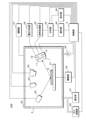
- a radiation detection device includes an openable and closable sample chamber in which a sample is placed, and a radiation detector that is placed inside the sample chamber and detects radiation generated from the sample. , adjusting the atmosphere by reducing the pressure inside the sample chamber in the closed state or filling it with a specific gas, and introducing air from outside the sample chamber into the inside of the sample chamber in the condition where the atmosphere has been adjusted.
- the radiation detector includes an atmosphere adjustment section and a control section, the radiation detector includes a radiation detection element, and a temperature sensor that measures an internal temperature of the radiation detector, and the control section includes a
- the atmosphere adjustment section is characterized in that the atmosphere adjusting section is controlled to adjust the timing of introducing air from outside the sample chamber into the sample chamber based on the temperature.
- the radiation detector further includes a housing that houses the radiation detection element therein, and the housing has an open opening. do.
- the control unit after detecting radiation using the radiation detection element, causes the voltage application unit to stop applying voltage to the radiation detection element;
- the method is characterized in that the illumination section is turned on after voltage application to the radiation detection element is stopped.
- an electric field (potential gradient) is generated in the semiconductor portion 112, in which the potential is higher as it approaches the signal output electrode 115 and becomes lower as it is farther from the signal output electrode 115.
- the electrode layer 113 is connected to the voltage application section 42 .
- a voltage is applied to the electrode layer 113 from the voltage application unit 42 so that the potential of the electrode layer 113 is between the innermost curved electrode 114 and the outermost curved electrode 114 . In this way, an electric field is generated inside the semiconductor section 112, the potential of which increases as it approaches the signal output electrode 115.
- the radiation detector 1 may include a control board that controls voltage application from the voltage application section 42 to the preamplifier 12. This control board performs a process of stopping voltage application from the voltage application unit 42 to the preamplifier 12 when the intensity of the signal output from the preamplifier 12 exceeds a predetermined threshold. The control board stops the operation of the preamplifier 12 by stopping the voltage application. When the illumination light enters the radiation detection element 11 and the intensity of the current signal output from the radiation detection element 11 via the preamplifier 12 increases significantly, a malfunction such as a failure may occur. The control board prevents malfunctions such as failure of the preamplifier 12 by stopping the operation of the preamplifier 12 when the output current signal is too large. The control board may be placed outside the radiation detector 1.
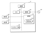
- the signal processing section 43 and the analysis section 44 correspond to a spectrum generation section.
- the display unit 46 displays the spectrum of radiation. The user can check the spectrum of the characteristic X-rays generated from the sample 6.
- the analysis unit 44 may further perform information processing based on the radiation spectrum. For example, the analysis unit 44 performs qualitative or quantitative analysis of elements contained in the sample 6 based on the spectrum of characteristic X-rays from the sample 6.
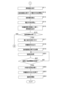
- the calculation unit 31 determines that the atmosphere adjustment has not been completed yet.
- the reference time is a time longer than the target time.
- the pressure of the inert gas or dry air inside the sample chamber 2 be at least one atmosphere. By setting the pressure to one atmosphere or more, air from outside the sample chamber 2 is prevented from entering.
- the reference time is predetermined so that the pressure of the supplied inert gas or dry air becomes one atmosphere or more within the sample chamber 2. If the atmosphere adjustment is not completed (S5: NO), the control unit 3 repeats the process of S5. Note that the control unit 3 may omit the process of S5.
- the control unit 3 After introducing external air into the sample chamber 2, the control unit 3 ends outputting the standby instruction (S23).
- the calculation unit 31 causes the display unit 46 to finish displaying the image including the standby instruction.
- the control section 3 then opens the lid section 20 (S24).
- the calculation section 31 controls the opening/closing section 41 to open the lid section 20 by transmitting a control signal to the opening/closing section 41 through the interface section 35.
- the opening/closing section 41 opens the lid section 20
- the sample chamber 2 is placed in an open state.
- a process may be performed that allows the user to open the lid 20 manually. With the sample chamber 2 open, work such as taking out or replacing the sample 6 is performed.
- the control unit 3 ends the process.
- the radiation detector 1 includes the collimator 14, but the radiation detector 1 may not include the collimator 14.
- the radiation detector 1 may have a configuration in which the opening 171 is not provided, the radiation detector 1 is provided with a window having a window material, and the radiation transmitted through the window is detected.
- the radiation detection element 11 is housed in the housing 17, but the radiation detector 1 may not include the housing 17.
- the radiation detection device 100 includes the irradiation unit 22, but the radiation detection device 100 may not include the irradiation unit 22.
- a mode is shown in which characteristic X-rays from the sample 6 are detected as radiation, but the radiation detection device 100 may be in a mode that detects radiation other than X-rays.
- the radiation detection device 100 may use a radiation detection element 11 other than a semiconductor element.
- the radiation detection device 100 may use a photomultiplier tube as the radiation detection element 11.
Landscapes
- Physics & Mathematics (AREA)
- Health & Medical Sciences (AREA)
- Life Sciences & Earth Sciences (AREA)
- General Physics & Mathematics (AREA)
- High Energy & Nuclear Physics (AREA)
- Molecular Biology (AREA)
- Spectroscopy & Molecular Physics (AREA)
- Chemical & Material Sciences (AREA)
- Analytical Chemistry (AREA)
- Biochemistry (AREA)
- General Health & Medical Sciences (AREA)
- Immunology (AREA)
- Pathology (AREA)
- Analysing Materials By The Use Of Radiation (AREA)
Priority Applications (1)
| Application Number | Priority Date | Filing Date | Title |
|---|---|---|---|
| JP2024524786A JPWO2023234153A1 (https=) | 2022-05-31 | 2023-05-25 |
Applications Claiming Priority (2)
| Application Number | Priority Date | Filing Date | Title |
|---|---|---|---|
| JP2022088954 | 2022-05-31 | ||
| JP2022-088954 | 2022-05-31 |
Publications (1)
| Publication Number | Publication Date |
|---|---|
| WO2023234153A1 true WO2023234153A1 (ja) | 2023-12-07 |
Family
ID=89024887
Family Applications (1)
| Application Number | Title | Priority Date | Filing Date |
|---|---|---|---|
| PCT/JP2023/019416 Ceased WO2023234153A1 (ja) | 2022-05-31 | 2023-05-25 | 放射線検出装置、制御方法及びコンピュータプログラム |
Country Status (2)
| Country | Link |
|---|---|
| JP (1) | JPWO2023234153A1 (https=) |
| WO (1) | WO2023234153A1 (https=) |
Cited By (1)
| Publication number | Priority date | Publication date | Assignee | Title |
|---|---|---|---|---|
| WO2025126801A1 (ja) * | 2023-12-14 | 2025-06-19 | 株式会社堀場製作所 | 放射線検出装置、制御方法及びコンピュータプログラム |
Citations (6)
| Publication number | Priority date | Publication date | Assignee | Title |
|---|---|---|---|---|
| JPS6025985U (ja) * | 1983-07-27 | 1985-02-21 | 日本電子株式会社 | エネルギ−分散型x線検出装置 |
| JPS6191548A (ja) * | 1984-10-12 | 1986-05-09 | Hitachi Ltd | 放射性金属酸化物の濃度分析方法 |
| JPS6454387A (en) * | 1987-08-05 | 1989-03-01 | Rinku Anariteikaru Ltd | X rays detector |
| JPH0869772A (ja) * | 1994-08-30 | 1996-03-12 | Nikon Corp | 走査型電子顕微鏡 |
| JPH10311879A (ja) * | 1997-05-10 | 1998-11-24 | Horiba Ltd | エネルギー分散型半導体x線検出器 |
| JP2019133787A (ja) * | 2018-01-30 | 2019-08-08 | 日本電子株式会社 | 荷電粒子線装置 |
-
2023
- 2023-05-25 JP JP2024524786A patent/JPWO2023234153A1/ja active Pending
- 2023-05-25 WO PCT/JP2023/019416 patent/WO2023234153A1/ja not_active Ceased
Patent Citations (6)
| Publication number | Priority date | Publication date | Assignee | Title |
|---|---|---|---|---|
| JPS6025985U (ja) * | 1983-07-27 | 1985-02-21 | 日本電子株式会社 | エネルギ−分散型x線検出装置 |
| JPS6191548A (ja) * | 1984-10-12 | 1986-05-09 | Hitachi Ltd | 放射性金属酸化物の濃度分析方法 |
| JPS6454387A (en) * | 1987-08-05 | 1989-03-01 | Rinku Anariteikaru Ltd | X rays detector |
| JPH0869772A (ja) * | 1994-08-30 | 1996-03-12 | Nikon Corp | 走査型電子顕微鏡 |
| JPH10311879A (ja) * | 1997-05-10 | 1998-11-24 | Horiba Ltd | エネルギー分散型半導体x線検出器 |
| JP2019133787A (ja) * | 2018-01-30 | 2019-08-08 | 日本電子株式会社 | 荷電粒子線装置 |
Cited By (1)
| Publication number | Priority date | Publication date | Assignee | Title |
|---|---|---|---|---|
| WO2025126801A1 (ja) * | 2023-12-14 | 2025-06-19 | 株式会社堀場製作所 | 放射線検出装置、制御方法及びコンピュータプログラム |
Also Published As
| Publication number | Publication date |
|---|---|
| JPWO2023234153A1 (https=) | 2023-12-07 |
Similar Documents
| Publication | Publication Date | Title |
|---|---|---|
| US20120051514A1 (en) | Methods and systems for producing visible light and x-ray image data | |
| Okada et al. | Photochromism and Thermally and Optically Stimulated Luminescences of AlN Ceramic Plate for UV Sensing. | |
| RU2472180C2 (ru) | Уменьшение эффектов захвата в сцинтилляторе за счет применения вторичного излучения | |
| JP6096418B2 (ja) | X線検出装置 | |
| US9892893B2 (en) | Cooled photomultiplier tube based light detector with reduced condensation, and related apparatuses and methods | |
| JP5928208B2 (ja) | 放射線検出器 | |
| WO2023234153A1 (ja) | 放射線検出装置、制御方法及びコンピュータプログラム | |
| JP2009285345A (ja) | マンモグラフィ装置及びそれを用いた撮影システム | |
| CN107957430B (zh) | X射线分析装置 | |
| CN103229043A (zh) | 量子产率测定装置 | |
| US20040109530A1 (en) | Radiation image radiographic apparatus | |
| WO2023234154A1 (ja) | 放射線検出装置、情報処理方法及びコンピュータプログラム | |
| CN100504442C (zh) | 用于固态探测器的连续吸湿器 | |
| CN118073215A (zh) | 一种原位退火多功能测试系统 | |
| JP5446182B2 (ja) | 透過型x線回折装置および透過型x線回折方法 | |
| JP2014057901A (ja) | マンモグラフィ装置及びそれを用いた撮影システム | |
| US6359962B1 (en) | Flourescent X-ray analyzer | |
| JP2004261306A (ja) | 乳房画像撮影装置 | |
| JP2009002795A (ja) | 蛍光x線分析装置 | |
| JP2006329944A (ja) | 蛍光x線分析装置 | |
| US20130223593A1 (en) | X-ray sensor, method for testing the x-ray sensor, and x-ray diagnostic device equipped with the x-ray sensor | |
| CN110031494A (zh) | 一种可测试材料的荧光光谱、余辉及荧光寿命的装置 | |
| JP2009068955A (ja) | 蛍光x線分析装置及び蛍光x線分析方法 | |
| WO2025126801A1 (ja) | 放射線検出装置、制御方法及びコンピュータプログラム | |
| JP2023056115A (ja) | 光安定性評価装置 |
Legal Events
| Date | Code | Title | Description |
|---|---|---|---|
| 121 | Ep: the epo has been informed by wipo that ep was designated in this application |
Ref document number: 23815911 Country of ref document: EP Kind code of ref document: A1 |
|
| WWE | Wipo information: entry into national phase |
Ref document number: 2024524786 Country of ref document: JP |
|
| NENP | Non-entry into the national phase |
Ref country code: DE |
|
| 122 | Ep: pct application non-entry in european phase |
Ref document number: 23815911 Country of ref document: EP Kind code of ref document: A1 |