WO2023233883A1 - コイル部品、およびこれを含むフィルタ回路 - Google Patents
コイル部品、およびこれを含むフィルタ回路 Download PDFInfo
- Publication number
- WO2023233883A1 WO2023233883A1 PCT/JP2023/016515 JP2023016515W WO2023233883A1 WO 2023233883 A1 WO2023233883 A1 WO 2023233883A1 JP 2023016515 W JP2023016515 W JP 2023016515W WO 2023233883 A1 WO2023233883 A1 WO 2023233883A1
- Authority
- WO
- WIPO (PCT)
- Prior art keywords
- coil
- electrode
- conductors
- conductor
- pair
- Prior art date
Links
- 239000012212 insulator Substances 0.000 claims abstract description 36
- 238000004804 winding Methods 0.000 claims abstract description 5
- 239000004020 conductor Substances 0.000 claims description 288
- 239000003990 capacitor Substances 0.000 claims description 25
- 230000002093 peripheral effect Effects 0.000 claims description 5
- 239000010410 layer Substances 0.000 description 106
- 230000004048 modification Effects 0.000 description 84
- 238000012986 modification Methods 0.000 description 84
- 239000000758 substrate Substances 0.000 description 28
- 230000003071 parasitic effect Effects 0.000 description 15
- 238000010586 diagram Methods 0.000 description 14
- 238000004519 manufacturing process Methods 0.000 description 13
- 239000000919 ceramic Substances 0.000 description 12
- 238000000034 method Methods 0.000 description 11
- 230000000052 comparative effect Effects 0.000 description 10
- 230000000694 effects Effects 0.000 description 9
- 239000000463 material Substances 0.000 description 9
- 230000008569 process Effects 0.000 description 6
- 238000012360 testing method Methods 0.000 description 6
- 230000008901 benefit Effects 0.000 description 3
- 230000017525 heat dissipation Effects 0.000 description 3
- 230000020169 heat generation Effects 0.000 description 3
- 238000010030 laminating Methods 0.000 description 3
- 229910002113 barium titanate Inorganic materials 0.000 description 2
- 239000003985 ceramic capacitor Substances 0.000 description 2
- 230000008878 coupling Effects 0.000 description 2
- 238000010168 coupling process Methods 0.000 description 2
- 238000005859 coupling reaction Methods 0.000 description 2
- 238000009826 distribution Methods 0.000 description 2
- XAGFODPZIPBFFR-UHFFFAOYSA-N aluminium Chemical compound [Al] XAGFODPZIPBFFR-UHFFFAOYSA-N 0.000 description 1
- 229910052782 aluminium Inorganic materials 0.000 description 1
- JRPBQTZRNDNNOP-UHFFFAOYSA-N barium titanate Chemical compound [Ba+2].[Ba+2].[O-][Ti]([O-])([O-])[O-] JRPBQTZRNDNNOP-UHFFFAOYSA-N 0.000 description 1
- 230000008859 change Effects 0.000 description 1
- 239000012141 concentrate Substances 0.000 description 1
- 238000010276 construction Methods 0.000 description 1
- 238000005336 cracking Methods 0.000 description 1
- 238000013016 damping Methods 0.000 description 1
- 230000007423 decrease Effects 0.000 description 1
- 230000003247 decreasing effect Effects 0.000 description 1
- 238000010304 firing Methods 0.000 description 1
- 238000007689 inspection Methods 0.000 description 1
- 238000003475 lamination Methods 0.000 description 1
- 238000007639 printing Methods 0.000 description 1
- 230000009467 reduction Effects 0.000 description 1
- 238000007650 screen-printing Methods 0.000 description 1
- 239000002356 single layer Substances 0.000 description 1
- 230000007847 structural defect Effects 0.000 description 1
- 230000001629 suppression Effects 0.000 description 1
Images


Classifications
-
- H—ELECTRICITY
- H01—ELECTRIC ELEMENTS
- H01F—MAGNETS; INDUCTANCES; TRANSFORMERS; SELECTION OF MATERIALS FOR THEIR MAGNETIC PROPERTIES
- H01F17/00—Fixed inductances of the signal type
-
- H—ELECTRICITY
- H01—ELECTRIC ELEMENTS
- H01F—MAGNETS; INDUCTANCES; TRANSFORMERS; SELECTION OF MATERIALS FOR THEIR MAGNETIC PROPERTIES
- H01F27/00—Details of transformers or inductances, in general
-
- H—ELECTRICITY
- H01—ELECTRIC ELEMENTS
- H01F—MAGNETS; INDUCTANCES; TRANSFORMERS; SELECTION OF MATERIALS FOR THEIR MAGNETIC PROPERTIES
- H01F27/00—Details of transformers or inductances, in general
- H01F27/28—Coils; Windings; Conductive connections
- H01F27/29—Terminals; Tapping arrangements for signal inductances
-
- H—ELECTRICITY
- H03—ELECTRONIC CIRCUITRY
- H03H—IMPEDANCE NETWORKS, e.g. RESONANT CIRCUITS; RESONATORS
- H03H7/00—Multiple-port networks comprising only passive electrical elements as network components
- H03H7/01—Frequency selective two-port networks
- H03H7/09—Filters comprising mutual inductance
Definitions
- the present disclosure relates to a coil component and a filter circuit including the same.
- noise countermeasures are taken using filter circuits that include coil components.
- a filter circuit uses a capacitor, which is a capacitance element, and therefore the noise suppression effect is reduced by the equivalent series inductance (ESL), which is the parasitic inductance of the capacitor.
- ESL equivalent series inductance
- Patent Document 1 discloses a coil component that cancels ESL by negative inductance generated by magnetically coupling two coils. More specifically, in Patent Document 1, of three stacked conductors, a first coil is configured by an upper layer wiring pattern and a part of a middle layer wiring pattern, and a lower layer wiring pattern and a part of a middle layer wiring A coil component is disclosed in which a second coil is formed by a part of the pattern.
- a portion where the first coil and the second coil join extends toward the side surface of the laminate, and is arranged on the side surface of the laminate. It is connected to the electrode (FIG. 3(b) of Patent Document 1).
- the first coil and the second coil are magnetically coupled and generate a negative parasitic inductance component. ESL can be canceled using this parasitic inductance component.
- An object of the present disclosure is to provide a coil component that can prevent variations in the size of parasitic inductor components, and a filter circuit including the same.
- a coil component according to an embodiment of the present disclosure is a coil component including a first coil and a second coil, an insulator on which the first coil and the second coil are arranged, and a plurality of insulators provided on the insulator.
- the insulator has a pair of main surfaces facing each other and a plurality of side surfaces connecting the pair of main surfaces, and the plurality of side surfaces include a first side surface, a second side surface, and a third side surface.
- the plurality of electrodes includes a first electrode provided on the first side, a second electrode provided on the second side, and a third electrode provided on the third side, and the first coil and the second coil are , the first coil and the second coil are arranged such that their winding axes face in the normal direction to the pair of main surfaces, at least a portion of the openings of each of the first coil and the second coil overlap and are magnetically coupled to each other, and the first end of the first coil a first end of the second coil is connected to a first electrode, a first end of the second coil is connected to a second electrode, and a second end of the first coil and a second end of the second coil are connected by a third electrode. has been done.
- a filter circuit includes the above-described coil component and a capacitor connected to the third electrode of the coil component.
- FIG. 1 is a transparent perspective view of a coil component according to Embodiment 1.
- FIG. 1 is a transparent plan view of a coil component according to Embodiment 1.
- FIG. 3 is a plan view for explaining a wiring pattern of the coil component according to the first embodiment.
- 1 is a circuit diagram of a filter circuit including a coil component according to Embodiment 1.
- FIG. 3 is a transparent side view showing a part of a coil component according to a second embodiment.
- FIG. 7 is a transparent side view showing a part of a coil component according to Embodiment 3;
- FIG. 7 is a transparent side view showing a part of a coil component according to a fourth embodiment.
- 7 is a plan view for explaining a wiring pattern of a coil component according to Modification 1.
- FIG. 1 is a transparent perspective view of a coil component according to Embodiment 1.
- FIG. 1 is a transparent plan view of a coil component according to Embodiment 1.
- FIG. 3 is
- FIG. 7 is a plan view for explaining a wiring pattern of a coil component according to a second modification. 7 is a transparent perspective view of a coil component according to modification example 3.
- FIG. FIG. 7 is a plan view of a coil component according to modification example 4.
- FIG. 7 is a plan view for explaining a wiring pattern of a coil component related to modification 5;
- FIG. 7 is a diagram showing an outline of a configuration when coil components related to modification 5 are stacked on top of each other.
- FIG. 7 is a diagram for explaining the principle of modification 5.
- FIG. FIG. 7 is a diagram for explaining the principle of modification 5.
- FIG. FIG. 7 is a diagram for explaining a comparative example regarding modification example 5.
- FIG. 7 is a diagram showing stress distribution in a cross section of a coil related to Modification Example 5.
- FIG. 1 is a transparent perspective view of a coil component 100 according to the first embodiment.
- FIG. 2 is a transparent plan view of the coil component 100 according to the first embodiment.
- FIG. 3 is a plan view for explaining the wiring pattern of the coil component 100 according to the first embodiment.
- the long side direction of the coil component 100 is the X direction
- the short side direction is the Y direction
- the height direction is the Z direction.
- the coil component 100 includes a coil L1 and a coil L2.
- the coil component 100 is composed of a ceramic layer laminate (insulator) 3 on which a substrate (ceramic green sheet) on which wiring patterns of a coil L1 (first coil) and a coil L2 (second coil) are formed is laminated. There is.
- the stacking direction of the ceramic layers is the Z direction, and the direction of the arrow indicates the upper layer direction.
- the laminate 3 has a pair of main surfaces facing each other and a plurality of side surfaces connecting the pair of main surfaces.
- first principal surface the top surface of the laminate 3
- second principal surface the bottom surface
- principal surface Sometimes referred to as the "principal surface.”
- a substrate on which the wiring pattern of the coil L1 is formed and a substrate on which the wiring pattern of the coil L2 is formed are stacked parallel to the main surface of the laminate 3 to form the coil L1 and the coil L2.
- FIGS. 1 to 3 illustrations of the respective substrates of the coil L1 and the coil L2 are omitted, and only the coil L1 and the coil L2 are shown.
- an electrode 4a (first electrode) is provided on one side (first side) of the two long sides of the laminate 3, and an electrode 4a (first electrode) is provided on the other side (second side). ) is provided with an electrode 4b (second electrode).
- an electrode 4c (third electrode) is provided on one side (third side)
- an electrode 4d (fourth electrode) is provided on the other side (fourth side). It is being As shown in FIGS. 1 and 2, the electrodes 4a to 4d are provided so as to extend from the side surface of the stacked body 3 to the first main surface and the second main surface.
- the coils L1 and L2 are arranged so that their winding axes are oriented in the normal direction to the main surface of the laminate 3, and have a rectangular shape.
- the coil L1 and the coil L2 are single-layer patterns, they are not closed patterns, but the shape of the opening is inferred from the pattern that produces the coil characteristics, other than the pattern for connecting to each electrode. is a rectangle.
- the openings of each of the coils L1 and L2 overlap each other and are magnetically coupled.
- FIG. 2 when the laminate 3 is viewed from the normal direction to the main surface, the opening pattern of the coil L1 and the opening pattern of the coil L2 overlap. Examples of rectangular openings include those with rounded coil wiring patterns and those with rounded corners.
- a coil L1 and a coil L2 having a wiring pattern as shown in FIG. 3 are arranged in an overlapping manner in the Z-axis direction. Thereby, the coil L1 and the coil L2 are arranged so that the openings thereof face in the normal direction to the main surface of the laminate 3.
- the wiring patterns of the coils L1 and L2 are formed, for example, by printing conductive paste (Ni paste) on a ceramic green sheet, which is a substrate, by a screen printing method.
- the laminate 3 is thus formed by laminating multiple layers of ceramic green sheets, which are substrates. Each layer constituting the laminate 3 is made of the same material. In this way, each layer of the laminate 3 is made of the same material, so after the lamination process of the laminate 3 is completed, during the batch firing process, the laminate 3 may peel or crack due to the difference in thermal expansion coefficient. This can prevent the possibility of this occurring.
- the coils L1 and L2 are each formed of one electrode layer (conductor). However, each of the coils L1 and L2 may be formed of a plurality of electrode layers (conductors). An example in which the coils L1 and L2 are formed of multiple electrode layers (conductors) will be described as a second embodiment.
- An end 91 (first end) of the coil L1 is connected to the electrode 4a.
- An end 93a (second end) of the coil L1 is connected to the electrode 4c.
- An end 92 (first end) of the coil L2 is connected to the electrode 4b.
- An end 93b (second end) of the coil L2 is connected to the electrode 4c. Therefore, the end 93a of the coil L1 and the end 93b of the coil L2 are connected by the electrode 4c.
- connection point between the coil L1 and the coil L2 exists at the electrode 4c.
- the distance from the connection point between coil L1 and coil L2 to electrode 4c is zero.
- the connection point between the coil L1 and the coil L2 will also be referred to as an "intermediate connection point.”
- the electrode 4c includes an intermediate connection point between the coil L1 and the coil L2.
- a current flowing from the electrode 4a (In) flows from the end 91 of the coil L1 to the end 93a, reaches the electrode 4c, and passes through the electrode 4c to the end 93b of the coil L2. flows into.
- the current flowing into the end 93b of the coil L2 flows into the end 92 of the coil L2 and reaches the electrode 4b (Out).
- the electrode 4a functions as an In terminal
- the electrode 4b functions as an Out terminal
- the electrode 4c functions as an intermediate connection terminal.
- the direction in which a magnetic field is generated when a current flows from the electrode 4a to the electrode 4c is the same as the direction in which a magnetic field is generated in the coil L2 when a current flows from the electrode 4c to the electrode 4b.
- FIG. 4 is a circuit diagram of filter circuit 1 including coil component 100 according to the first embodiment.
- the filter circuit 1 is, for example, an EMI removal filter, and is a third-order T-type LC filter circuit.
- a coil component 100 is used in this filter circuit 1.
- a third-order T-type LC filter circuit is used as the configuration of the filter circuit 1, but a fifth-order T-type LC filter circuit or a higher-order T-type LC filter circuit may be used.
- the coil component 100 having a similar configuration can also be applied to the above.
- the filter circuit 1 to which the coil component 100 is applied includes a capacitor C1 in addition to the coil component.
- the capacitor C1 is connected to the coil component 100.
- the capacitor C1 has one end connected to an electrode 4c that constitutes an intermediate connection point between the coil L1 and the coil L2, and the other end connected to the GND wiring.
- the capacitor C1 is constituted by, for example, a multilayer ceramic capacitor mainly composed of BaTiO3 (barium titanate).
- a multilayer ceramic capacitor mainly composed of other materials may be used.
- other types of capacitors such as an aluminum electrolytic capacitor may be used as the capacitor C1.
- the capacitor C1 has an inductor L3 as a parasitic inductance (equivalent series inductance (ESL)). As shown in FIG. 4, capacitor C1 is represented by a circuit configuration in which inductor L3 is connected in series with capacitor C1a. Note that the capacitor C1 may be configured so that the parasitic resistance (equivalent series resistance (ESR)) is equivalent to a circuit configuration in which the inductor L3 and the capacitor C1a are connected in series.
- ESR Equivalent series resistance
- the coil L1 and the coil L2 are magnetically coupled, producing a negative inductance component (-M) in series with the capacitor C1.
- This negative inductance component is shown as an inductor of -M in FIG.
- This negative inductance component can cancel the parasitic inductance (inductor L3) of the capacitor C1.
- the parasitic inductance component of the capacitor C1 can be made smaller in appearance.
- a filter circuit 1 composed of a capacitor C1, a coil L1, and a coil L2 cancels out the parasitic inductance of the capacitor C1 with a negative inductance component due to the mutual inductance between the coil L1 and the coil L2, thereby reducing the noise damping effect in the high frequency band. can be improved.
- the intermediate connection point between the coil L1 and the coil L2 exists at the electrode 4c.
- neither the coil L1 nor the coil L2 is provided with a wiring pattern extending from the intermediate connection point between the coil L1 and the coil L2 to the electrode 4c. Therefore, compared to the conventional configuration in which a wiring pattern is provided from the intermediate connection point between the coil L1 and the coil L2 to the electrode 4c, the distance of the wiring pattern does not change due to manufacturing variations, so the parasitic inductance It is possible to prevent variations in the size of the components. Since the coil component 100 according to the first embodiment is not provided with an extra wiring pattern that causes variations in the magnitude of the parasitic inductance component, there is no parasitic inductance component that depends on the wiring pattern.
- the coil component 100 it is possible to reduce the effort and cost required to maximize accuracy in order to suppress such variations. Therefore, according to the first embodiment, it is possible to provide a coil component that can prevent variations in the size of parasitic inductor components and a filter circuit including the coil component.
- the coil component 100 when used as a component for removing noise from a power line and current is caused to flow from the electrode 4a to the electrode 4b, the current flowing inside the laminate 3 passes through the electrode 4c outside the laminate 3. At this time, compared to the conventional pattern in which the current continues to flow inside the laminate 3, the electrode 4c exhibits a heat dissipation function, and the heat generated by the current is dissipated in the electrode 4c. Therefore, the heat dissipation effect of the coil component 100 can be improved.
- the coil component 100 according to the first embodiment has the effect that the procedure for testing continuity of the electrodes 4a to 4c and the coils L1 and L2 can be simplified.
- a conventional coil component in which a wiring pattern is provided from the intermediate connection point between coil L1 and coil L2 to electrode 4c, it is not possible to test the continuity between coil L1 and coil L2 by simply testing the continuity between electrode 4a and electrode 4b. It is not possible to confirm that there is no problem in conduction between the intermediate connection point and the electrode 4c. Since another wire is inserted between the intermediate connection point between the coil L1 and the coil L2 and the electrode 4c, it is necessary to inspect the disconnection state of this other wire and the connection state between this other wire and the electrode 4c. .
- the electrode 4c corresponding to the intermediate connection terminal functions as a conduction line that connects the coil L1 and the coil L2. Therefore, in the coil component 100, by testing the continuity between the electrodes 4a and 4b, it is possible to complete the continuity test of the electrodes 4a to 4c and the coils L1 and L2.
- the electrodes 4a and 4b function as mounting terminals connected in series to the power line. That is, the electrode 4a and the electrode 4b are constituted by mounting terminals.
- the size of the mounting terminals can be made larger compared to the case where the electrodes 4a and 4b are provided on the short sides of the laminate 3. can do.
- the heat generated in the mounting portion can be sufficiently dissipated by the width of the electrode.
- the end portion 91 of the coil L1 is disposed on the wide electrode 4a on the long side of the laminate 3, and the end 91 of the coil L1 is arranged on the wide electrode 4a on the long side of the laminate 3.
- the end portion 92 of the coil L2 is arranged at 4b, it is also possible to form a coil with a large opening by taking advantage of the distance from one end of the long side to the other end.
- Embodiment 1 discloses "a coil component in which the insulating layer constituting the first coil and the insulating layer constituting the second coil are composed of insulators made of the same material.”
- Embodiment 2 Next, a second embodiment will be described with reference to FIG.
- the coils L1 and L2 are formed of multiple electrode layers (conductors).
- the second embodiment has the same configuration as the first embodiment except that the coils L1 and L2 are formed of multiple electrode layers (conductors). Therefore, as in the first embodiment, the aperture pattern of the coil L1 and the aperture pattern of the coil L2 overlap when viewed from the normal direction of the aperture patterns.
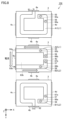
- FIG. 5 is a transparent side view showing a part of the coil component 101 according to the second embodiment.
- FIG. 5(A) shows the vicinity of the electrode 4a of the coil component 101
- FIG. 5(B) shows the vicinity of the electrode 4b of the coil component 101
- FIG. 5(C) shows the vicinity of the electrode 4c of the coil component 101. It is.
- each of the coils L1 and L2 is formed of three electrode layers (conductors).
- FIG. 5 shows conductors 10a to 10c (first conductors) included in the ceramic green sheets in each layer of coil L1 and conductors 20a to 20c (second conductors) included in the ceramic green sheets in each layer of coil L2. has been done.
- the coil L1 is configured to include a plurality of conductors 10a to 10c laminated in the normal direction to the main surface of the laminate 3, and the coil L2 is configured to include It is configured to include a plurality of conductors 20a to 20c laminated in the normal direction to the main surface of the body 3.
- the materials of the ceramic green sheets of each layer are all the same. That is, in the second embodiment, like the first embodiment, each layer of the laminate 3 is made of the same material.
- each of the plurality of conductors 10a to 10c constituting the coil L1 has the same line shape (wiring pattern), and the plurality of conductors 20a constituting the coil L2 have the same line shape (wiring pattern).
- the line shape (wiring pattern) of each of the lines 20c to 20c is common.
- one end of the conductors 10a to 10c forming the coil L1 is connected to the electrode 4a. Therefore, the end 91 of the coil L1 is constituted by one end of the conductors 10a to 10c.
- one end of the conductors 20a to 20c forming the coil L2 is connected to the electrode 4b. Therefore, the end 92 of the coil L2 is constituted by one end of the conductors 20a-20c.
- end 93a of coil L1 is constituted by the other ends of conductors 10a-10c
- end 93b of coil L2 is constituted by the other ends of conductors 20a-20c.
- the conductors 10a to 10c are connected in parallel with the electrode 4a and the electrode 4c.
- Conductors 20a to 20c are connected in parallel with electrode 4b and electrode 4c.
- a parallel circuit made up of the conductors 10a to 10c and a parallel circuit made up of the conductors 20a to 20c are constructed.
- the ends 911-913 of the conductors 10a-10c are connected in parallel to the electrode 4a, and the ends 931a-933a of the conductors 10a-10c are connected in parallel to the electrode 4c.
- the ends 911 to 913 constitute the end 91 of the coil L1, and the ends 931a to 933a constitute the end 93a of the coil L1.
- Ends 921-923 of the conductors 20a-20c are connected in parallel to the electrode 4b, and ends 931b-933b of the conductors 20a-20c are connected in parallel to the electrode 4c.
- the ends 921 to 923 constitute the end 92 of the coil L2, and the ends 931b to 933b constitute the end 93b of the coil L2.
- the via conductors that connect the conductors 10a to 10c in parallel and the via conductors that connect the conductors 20a to 20c in parallel are not provided. That is, a via conductor connecting each of the conductors 10a to 10c is not provided between the end 91 of the coil L1 and the end 93a of the coil L1, and the end 92 of the coil L2 and the end 93a of the coil L2 are not provided. 93b, no via conductor is provided to connect each of the conductors 20a to 20c.
- the coil component 101 In the coil component 101 according to the second embodiment, current flows in parallel circuits in the conductors 10a to 10c and the conductors 20a to 20c laminated in multiple layers. Therefore, the coil component 101 can handle a large current.
- the electrodes 4a and 4c are used as wiring members for configuring the parallel circuit of the conductors 10a to 10c without using via conductors.
- the electrodes 4b and 4c are used as wiring members for configuring the parallel circuit of the conductors 20a to 20c without using via conductors. Therefore, according to the second embodiment, the cost for providing via conductors can be reduced. Furthermore, according to the second embodiment, it is possible to prevent peeling, cracking, etc. from occurring in the laminate 3 starting from the via conductor.
- the insulating layer when the conductors 10a to 10c are laminated and the insulating layer when the conductors 20a to 20c are laminated are made of an insulator made of the same material. . Therefore, in the second embodiment, "an insulating layer when a plurality of first conductors constituting a first coil are laminated and an insulating layer when a plurality of second conductors constituting a second coil are laminated are as follows. A coil component composed of an insulator made of the same material is disclosed.
- a three-layer conductor is used as an example in which the coils L1 and L2 are formed by conductors laminated in multiple layers.
- the number of conductor layers is not limited to three layers, and may be two layers or four or more layers.
- the conductors 10a to 10c stacked in multiple layers are connected at the electrodes 4a and 4c.
- it may be configured such that only some of the conductors 10a to 10c are connected to one of the electrodes 4a and 4c.
- any part of the conductors 10a to 10c may be connected using a via conductor.
- the conductors 20a to 20c may be configured such that only some of the conductors 20a to 20c are connected to one of the electrodes 4b and 4c.
- Embodiment 3 Next, a third embodiment will be described with reference to FIG.
- the third embodiment can be understood as a modification of the second embodiment.
- an example has been described in which via conductors are not used to configure parallel circuits of conductors 10a to 10c and conductors 20a to 20c.
- Embodiment 3 an example of configuring these parallel circuits using via conductors will be described.
- FIG. 6 is a transparent side view showing a part of the coil component 102 according to the third embodiment.
- FIG. 6(A) shows the vicinity of the electrode 4a of the coil component 102
- FIG. 6(B) shows the vicinity of the electrode 4b of the coil component 102
- FIG. 6(C) shows the vicinity of the electrode 4c of the coil component 102. It is.
- a pair of via conductors are connected near both ends of conductors 10a to 10c 51, and a pair of via conductors 52 connect the vicinity of both ends of the conductors 20a to 20c.
- a parallel circuit of the conductors 10a to 10c is formed in front of the electrodes 4a and 4c. Only one of the conductors 10a to 10c, for example, the conductor 10b, is connected to the electrode 4a and the electrode 4c.
- the via conductor 51 it is preferable to provide the via conductor 51 as close as possible to one end 91 and the other end 93a of the coil L1. Further, with such a configuration, it is possible to reduce locations where current density is high in each layer of the coil L1.
- a parallel circuit of the conductors 20a to 20c is formed in front of the electrodes 4a and 4c. Only one of the conductors 20a to 20c, for example, the conductor 20b, is connected to the electrode 4a and the electrode 4c.
- the via conductor 52 it is preferable to provide the via conductor 52 as close as possible to one end 92 and the other end 93b of the coil L2. Furthermore, with such a configuration, it is possible to reduce the number of locations where the current density is high in each layer of the coil L2.
- a parallel circuit is configured by the pair of via conductors 51 that connect the conductors 10a to 10c near both ends of the conductors 10a to 10c, and the conductors 10a to 10c.
- a parallel circuit is configured by a pair of via conductors 52 that connect the conductors 20a to 20c near both ends of the conductors 20a to 20c, and the conductors 20a to 20c.
- each of the conductors 10a to 10c is connected by a via conductor 51 near the end 93a of the coil L1, and each of the conductors 20a to 20c is connected to the via conductor 51 near the end 93b of the coil L2. 52.
- the vicinity of the end 93a of the coil L1 refers to a position as close as possible to the end 93a of the coil L1 without causing any problem in providing the via holes of the via conductor 52 in the conductors 20a to 20c.
- the conductors 10a to 10c there is a via conductor 52 in a portion that connects a wiring pattern that functions as a coil (a wiring pattern that forms an opening) and an electrode 4c.
- the side of the end 93b of the coil L2 includes the vicinity of the end 93b of the coil L2, and refers to a position closer to the end 93b than the midpoint between the ends 93b and 92 of the conductors 20a to 20c.
- the coil component 102 in the coil component 102 according to the third embodiment, among the conductors 10a to 10c composed of three layers, only the middle layer conductor 10b is connected to the electrode 4a. Other conductors 10a and 10c are connected to electrode 4a via conductor 10b and via conductor 51. If all of the conductors 10a to 10c are connected to the electrode 4a as in the second embodiment described above, there is no need to provide the via conductor 51.
- the conductor 10b is connected to the electrode 4a among the conductors 10a to 10c composed of three layers. Furthermore, for the same reason, the electrode 4b and the electrode 4c also have a similar configuration. Therefore, according to the coil component 102 according to the third embodiment, it is possible to prevent cracks from occurring in the laminate 3 during the manufacturing process of the laminate 3. Of course, if cracks are unlikely to occur during manufacturing, all of the conductors 10a to 10c are connected to the electrodes 4a and 4c, and similarly, all of the conductors 20a to 20c are connected to the electrodes 4b and 4c, and the vias are connected. A configuration in which the conductors 51 and 52 are not provided may also be adopted.
- the conductors connected to any of the electrodes 4a to 4c are the middle layer conductors 10b and 20b.
- the middle layer conductors 10b, 20b instead of the middle layer conductors 10b, 20b, the upper layer conductors 10a, 20a or the lower layer conductors 10c, 20c may be selected as the conductor to be connected to any of the electrodes 4a to 4c.
- two of the conductors 10a to 10c may be selected as the target, and similarly, two of the conductors 20a to 20c may be selected as the target.
- Embodiment 3 an example has been described in which a parallel circuit is configured by the conductors 10a to 10c and a pair of via conductors 51 that connect the conductors 10a to 10c near both ends of the conductors 10a to 10c. Similarly, an example has been described in which a parallel circuit is configured by a pair of via conductors 52 connecting the conductors 20a to 20c near both ends of the conductors 20a to 20c, and the conductors 20a to 20c.
- the configuration near the electrode 4a the configuration shown in FIG. 5(A) described as the second embodiment may be adopted.
- a parallel circuit is formed by the conductors 10a to 10c between the electrode 4a and the via conductor 51 near the end 93a of the conductors 10a to 10c.
- the structure near the electrode 4b may adopt the structure shown in FIG. 5(B) described as the second embodiment.
- a parallel circuit is formed by the conductors 20a to 20c between the electrode 4b and the via conductor 52 near the end 93b of the conductors 20a to 20c.
- Embodiment 4 Next, a fourth embodiment will be described with reference to FIG.
- the fourth embodiment can be understood as a modification of the third embodiment.
- the third embodiment an example has been described in which via conductors 51 and 52 are used to configure parallel circuits of conductors 10a to 10c and conductors 20a to 20c, respectively.
- a via conductor is further provided in each of the parallel circuits of the conductors 10a to 10c and the conductors 20a to 20c configured according to the third embodiment.
- FIG. 7 is a transparent side view showing a part of the coil component 103 according to the fourth embodiment.
- FIG. 7(A) shows the vicinity of the electrode 4a of the coil component 103
- FIG. 7(B) shows the vicinity of the electrode 4b of the coil component 103
- FIG. 7(C) shows the vicinity of the electrode 4c of the coil component 103. It is.
- the conductors 10a to 10c are A pair of via conductors 53 connecting the conductors 20a to 20c and a pair of via conductors 54 connecting the conductors 20a to 20c near both ends of the conductors 20a to 20c are further added.
- the fourth embodiment even if a connection failure occurs in one of the via conductors 51 and 53 provided near both ends of the conductors 10a to 10c, conduction can be maintained by the other. Similar effects can be achieved with the conductors 20a to 20c.
- additional via conductors are provided near both ends of the conductors 10a to 10c and the conductors 20a to 20c.
- additional via conductors may be provided only near one end of conductors 10a-10c and near one end of conductors 20a-20c.
- a via conductor 53 may be provided near the center of the conductors 10a to 10c, and a via conductor 54 may be similarly provided near the center of the conductors 20a to 20c.
- the positions where the via conductors 53 and 54 are provided are not limited to the vicinity of both ends of the conductors 10a to 10c and the conductors 20a to 20c.
- FIG. 8 is a plan view for explaining the wiring pattern of the coil component 104 according to the first modification.
- the coil L1 is constituted by first coil parts A1 and A2
- the coil L2 is constituted by second coil parts B1 and B2.
- the first coil part A1 is composed of a substrate (ceramic green sheet) on which the wiring pattern of the first coil part A1 is formed.
- the second coil portion B1 is constituted by a substrate on which the wiring pattern of the second coil portion B1 is formed.
- the first coil part A2 and the second coil part B2 are formed of a substrate on which the wiring pattern of the first coil part A2 and the wiring pattern of the second coil part B2 are formed.
- Coil L1 and coil L2 according to Modification Example 1 are composed of these three substrates (ceramic green sheets), in the Z-axis direction, from below, a substrate on which the wiring pattern of second coil part B1 is formed, and first coil part A2.
- a substrate having a wiring pattern formed thereon and a wiring pattern of the second coil part B2, and a substrate having a wiring pattern of the first coil part A1 formed thereon are laminated in this order.
- the coil L1 according to Modification 1 is composed of first coil parts A1 and A2.
- Coil L2 according to Modification 1 is comprised of second coil parts B1 and B2. Therefore, in Modification 1, the first coil part A2 that constitutes a part of the coil L1 and the second coil part B2 that constitutes a part of the coil L2 are arranged in the same layer.
- the first coil portion A1 and the first coil portion A2 are connected by via conductors 55 and 56.
- the via conductor 55 connects the connecting portion 65a of the first coil portion A1 and the connecting portion 65b of the first coil portion A2.
- the via conductor 56 connects the connecting portion 66a of the first coil portion A1 and the connecting portion 66b of the first coil portion A2.
- the second coil part B1 and the second coil part B2 are connected by via conductors 57 and 58.
- the via conductor 57 connects the connecting portion 67a of the second coil portion B1 and the connecting portion 67b of the second coil portion B2.
- the via conductor 58 connects the connecting portion 68a of the second coil portion B1 and the connecting portion 68b of the second coil portion B2.
- the end 91 of the coil L1 is connected to the electrode 4a.
- An end 93a of the coil L1 is connected to the electrode 4c.
- An end 92 of the coil L2 is connected to the electrode 4b.
- An end 93b of the coil L2 is connected to the electrode 4c.
- the electrode 4c includes an intermediate connection point between the coil L1 and the coil L2.
- the current flowing from the electrode 4a flows through the first coil portion A1 that constitutes the first layer of the coil L1, passes through the via conductors 55 and 56, and flows through the second layer of the coil L1. This leads to the first coil portion A2 that constitutes the.
- the current flowing into the first coil portion A2 flows leftward in the drawing and reaches the end portion 93a.
- the current that has reached the end portion 93a flows into the second coil portion B2, which constitutes the first layer of the coil L2, via the electrode 4c.
- the current flowing into the second coil portion B2 flows rightward in the drawing. Thereafter, the current passes through the via conductors 57 and 58 and reaches the second coil portion B1 that constitutes the second layer of the coil L2.
- the current flowing into the second coil portion B1 flows to the end portion 92 and reaches the electrode 4b.
- the end 93a of the coil L1 and the end 93b of the coil L2 are arranged at positions that do not overlap with each other.
- the electrode 4c including the intermediate connection point between the coil L1 and the coil L2 the end 93a of the coil L1 and the end 93b of the coil L2 are located apart in the y-axis direction.
- the end 93a of the coil L1 and the end 93a of the coil L2 are 93b are arranged in the electrode 4c so that the green sheets overlap each other with a small thickness between the laminated layers.
- the end 93a of the coil L1 and the end 93b of the coil L2 are arranged to overlap at the electrode 4c, the end 93a of the coil L1 and the end 93b of the coil L2 are Since the magnetic fields cancel each other out between them, the mutual inductance between the coil L1 and the coil L2 decreases.
- the end 93a of the coil L1 and the end 93b of the coil L2 are located at separate positions in the y-axis direction, and the end 93a of the coil L1 includes the end 93a of the coil L1.
- the first coil portion A2 and the second coil portion B2 including the end portion 93b of the coil L2 are located at separate positions on the same layer.
- the mutual inductance value can be adjusted to the required value.
- This method of preventing the wiring pattern of the coil L1 and the wiring pattern of the coil L2 in the region connected to the electrode 4c from overlapping when viewed from the stacking direction can also be applied to the first embodiment. For example, by expanding the electrode 4c in the Y-axis direction in FIG. 3, shifting the position of the end 93a in the +Y-axis direction, and shifting the position of the end 93b in the -Y-axis direction, a positional relationship that does not overlap when viewed from the stacking direction can be achieved. can do.
- the directions in which the ends 93a and 93b are shifted may be reversed.
- the coil L1 is composed of a plurality of first coil parts A1 and A2, and the coil L2 is composed of a plurality of second coil parts B1 and B2. Therefore, the degree of freedom in designing the coils can be increased compared to the case where the coils L1 and L2 are constructed from a single component.
- the performance of a coil is determined by the aperture, number of turns, etc.
- the degree of freedom of opening is limited, so it is necessary to adjust the performance of the coil by changing the number of turns.
- the number of turns of the coil can be finely adjusted in units of, for example, 0.5 rotations. It is also possible to form the coils L1 and L2 in separate layers for each 0.5 rotation, but by forming them in the same layer, the number of steps can be reduced and costs can be reduced.
- FIG. 9 is a plan view for explaining the wiring pattern of the coil component 105 according to the second modification.
- Modification 2 an example will be described in which the opening of the coil is expanded using the electrode 4d that is not used in each embodiment.
- the coil L1 is composed of first coil parts A11 and A12
- the coil L2 is composed of second coil parts B11 and B12.
- the first coil part A11 is composed of a substrate (ceramic green sheet) on which the wiring pattern of the first coil part A11 is formed.
- the second coil portion B11 is configured by a substrate on which a wiring pattern of the second coil portion B11 is formed.
- the first coil portion A12 and the second coil portion B12 are configured by a substrate on which a wiring pattern of the first coil portion A12 and a wiring pattern of the second coil portion B12 are formed.
- the coil L1 and the coil L2 according to Modification Example 2 are composed of these three substrates (ceramic green sheets), which in the Z-axis direction are, from below, a substrate on which the wiring pattern of the second coil part B11 is formed, and a first coil part A12. It is constructed by laminating in this order a substrate on which the wiring pattern of and the wiring pattern of the second coil portion B12 are formed, and a substrate on which the wiring pattern of the first coil portion A11 is formed.
- the coil L1 according to Modification 2 is composed of first coil parts A11 and A12.
- Coil L2 according to modification 2 is configured by second coil parts B11 and B12.
- the first coil portion A11 and the first coil portion A12 are connected by an electrode 4d that was not used in each embodiment.
- the second coil portion B11 and the second coil portion B12 are connected by via conductors 59 and 60.
- the via conductor 59 connects the connecting portion 69a of the second coil portion B11 and the connecting portion 69b of the second coil portion B12.
- the via conductor 60 connects the connecting portion 70a of the second coil portion B11 and the connecting portion 70b of the second coil portion B12.
- the end 91 of the coil L1 is connected to the electrode 4a.
- An end 93a of the coil L1 is connected to the electrode 4c.
- An end 92 of the coil L2 is connected to the electrode 4b.
- An end 93b of the coil L2 is connected to the electrode 4c.
- the electrode 4c includes an intermediate connection point between the coil L1 and the coil L2.
- the current flowing from the electrode 4a flows through the first coil portion A11 constituting the first layer of the coil L1, passes through the outer electrode 4d of the laminate 3, and flows into the coil L1.
- the current flowing into the first coil portion A12 flows into the second coil portion B12, which constitutes the first layer of the coil L2, via the electrode 4c.
- the current flowing into the second coil portion B12 passes through the via conductors 59 and 60 and reaches the second coil portion B11 that constitutes the second layer of the coil L2.
- the current flowing into the second coil portion B11 flows to the end portion 92 and reaches the electrode 4b.
- the opening is expanded by utilizing the electrode 4d (Non connect terminal) that does not contribute to either the current In terminal or Out terminal or the intermediate connection terminal of L1 and L2.
- the electrode 4d can be utilized as one of the means for adjusting the inductance component.
- FIG. 10 is a transparent perspective view for explaining the wiring pattern of the coil component 106 according to the third modification.
- Modification 3 is a straight line that passes through the center of the opening in the Z-axis direction through the coils L1 and L2 shown in FIG. It corresponds to the image rotated 90 degrees around .
- the end 91 of the coil L1 is connected to the electrode 4a installed on the short side.
- An end 93a of the coil L1 is connected to an electrode 4c installed on the long side.
- the end 92 of the coil L2 is connected to the electrode 4b installed on the short side.
- An end 93b of the coil L2 is connected to the electrode 4c. Therefore, in the third modification, the intermediate connection point between the coil L1 and the coil L2 is located at the electrode 4c on the side surface including the long side of the laminate 3.
- the electrode 4c is provided on the side surface on the long side of the laminate 3, by taking advantage of the length of the long side, the electrode 4c can be made smaller in size than the electrode 4b provided on the side surface on the short side of the laminate 3. It can be made larger.
- the electrode located at the intermediate connection point between the coil L1 and the coil L2 functions to radiate heat generated by the current.
- this function is performed by the electrode 4c on the shorter side of the laminate 3.
- this function is performed by the electrodes 4a on the long sides of the laminate 3. Since the size of the electrode 4a can be made larger than the electrode 4c, according to the third modification, the heat dissipation effect at the intermediate connection point between the coil L1 and the coil L2 can be further enhanced.
- the distance between the end 93a of the coil L1 and the end 93 of the coil L2 can be sufficiently increased by taking advantage of the length of the electrode 4a in the long side direction. Thereby, it is possible to prevent the inductances of the coils L1 and L2 from canceling each other out at the intermediate connection point. In particular, when Modification 3 is applied to Modifications 1 and 2, the effect is maximized.
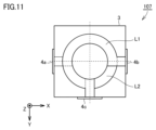
- FIG. 11 is a plan view for explaining the wiring pattern of the coil component 107 according to the fourth modification.
- the lengths of the sides on which the electrodes 4a, 4b, and 4c exist are equal, and the shape is square when viewed from the stacking direction.
- the coils L1 and L2 are configured in a circular shape. By making the coil circular, there are no places where the current density is locally high, so even when a large current is passed, local heat generation and associated failures are less likely to occur. Similar effects can be expected by forming a circular or oval shape on a rectangular chip as in the examples up to Modification Example 3.
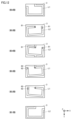
- FIG. 12 is a plan view for explaining the wiring pattern of the coil component 108 according to the fifth modification.
- FIG. 13 is a diagram schematically showing a configuration when coil components 108 according to modification 5 are stacked on top of each other.
- the coil component 108 according to Modification 5 is configured by stacking six substrates on which the wiring pattern of the coil L1 or the coil L2 is formed.
- FIG. 12 shows wiring patterns formed on each of the first to sixth layer substrates. The first layer substrate is located at the bottom layer, and the sixth layer substrate is located at the top layer. In FIGS. 12 and 13, illustration of the electrodes 4a and 4c is omitted.
- the coils L1 and L2 shown in FIG. 12 have a rectangular shape like the coils L1 and L2 shown in FIG. 3.
- Coils L1 and L2 related to modification 5 are examples of a first conductor, a second conductor, and a third conductor that are laminated in the normal direction to the main surface. Each of the first conductor, second conductor, and third conductor has a rectangular shape.
- the coil L2 provided on the first layer substrate and the coil 1 provided on the sixth layer substrate are larger than the coils L1 and L2 provided on each of the second to fifth layers.
- the coils L1 and L2 provided in each of the second to fifth layers rotate about the center of the opening of the coil L2 provided in the first layer substrate, with reference to the coil L2 provided in the first layer substrate.
- the fourth layer coil L2 and the fifth layer coil L2 are connected by via conductors 81, 81.
- the second layer coil L1 and the third layer coil L1 are connected by via conductors 88 and 82.
- the coils L1 and L2 of each layer are stacked in the main surface direction (Z-axis direction).
- the coils L1 and L2 of the second to fifth layers are arranged inside the outer peripheral edge of the coil L1 of the first layer and the coil L2 of the second layer.
- each side of the coils L1 and L2 in each layer constitutes an outer peripheral edge and an inner peripheral edge of the wiring pattern of the coils L1 and L2 in each layer.
- each side of the coils L1 and L2 in each layer may be referred to as an edge.
- FIG. 13 shows L1 and L2 superimposed in the main surface direction (Z-axis direction) together with a schematic diagram.
- the coil component 108 when the laminate 3 is viewed from the normal direction to the pair of principal surfaces, the corresponding sides of each of the first conductor, second conductor, and third conductor constituting L1 and L2 are intersect. Further, the size of the first conductor (L2 of the first layer, L1 of the sixth layer) is larger than the size of the second conductor and the third conductor (L1, L2 of the second to fifth layers). Further, the second conductor and the third conductor (L1, L2 of the second to fifth layers) are arranged inside the outer edge of the first conductor (L2 of the first layer, L1 of the sixth layer). .
- each of the coil parts A21 to A23 shows a simplified wiring pattern of either L1 or L2 of the coil component 108.
- the sides (edges) of each of the coil portions A21 to A23 intersect.
- the coil portions A22 and A23 are included within the range of the outer peripheral edge of the coil portion A21.
- the symbol IP indicates the intersection of any two sides of the coil portions A21 to A23.
- the fifth modification there is a location where the sides of two of the coil parts A21 to A23 intersect.
- the sides of the coil portions A21 to A23 do not intersect at one location.
- the six layers do not intersect at one location, and the overlap of edges is limited to a maximum of four layers.
- stress concentration points can be distributed to various locations without concentrating stress on one side of the coil portion. As a result, it is possible to prevent cracks and the like from occurring in the coil component 108.
- FIGS. 14 and 15 are diagrams for explaining the principle of the fifth modification.
- FIG. 14(A) shows an example in which the coil parts A21 and A22 are stacked so that the wiring patterns of the coil parts A21 and A22 completely overlap.
- FIG. 14(B) shows an example in which the coil parts A21 and A22 are stacked such that the side of the coil part A21 and the side of the coil part A22 intersect at an appropriate angle.
- FIG. 14(C) shows an example in which the angle at which the side of the coil portion A21 and the side of the coil portion A22 intersect is larger than the configuration shown in FIG. 14(B).
- the sides of the coil part A21 and the sides of the coil part A22 are connected to each other to the extent that a plurality of gaps G1 appear between the sides of the coil part A21 and the sides of the coil part A22.
- the amount of deviation between In other words, in the configuration shown in FIG. 14C, the amount of deviation between the side of the coil portion A21 and the side of the coil portion A22 is large to the extent that it exceeds the coil width W1.
- the number of intersection points IP of each side of the coil portions A21 and A22 is greater than in the configuration shown in FIG. 14(B). Therefore, it is desirable that the amount of angular deviation between the side of the coil portion A21 and the side of the coil portion A22 does not exceed the coil width W1. Note that the preferable amount of angle deviation between the side of the coil portion A21 and the side of the coil portion A22 differs depending on the coil width and coil length.
- FIG. 15 shows an example in which three coil portions A21 to A23 are overlapped. If the principle explained using FIG. 14 is directly applied to the three coil portions A21 to A23, the configuration shown in FIG. 15(A) will be obtained.
- the outer diameter of the coil portion A21 is made larger than the outer diameter of the coil portions A22 and A23. That is, in order to reduce the overlap of the edges of the wiring patterns of the coil portion, "a wiring pattern having a size different from the wiring pattern shown in FIG. 15(A)" is adopted. More specifically, the size and position of the coil portions are adjusted so that the coil portions A22 and A23 are included within the outer circumferential edge of the coil portion A21. As a result, there is no intersection IP where the edges of all layers overlap as shown in FIG. 15(A).
- the coil component 108 related to Modification 5 was devised based on the principle explained above.
- the coil part A22 constituting the coil component 108 has a configuration in which it is rotated by a predetermined angle about the center of the opening of the coil part A22 in the XY plane as a rotation axis.
- the coil portion A23 constituting the coil component 108 has a configuration in which the center of the opening of the coil portion A23 in the XY plane is rotated by a predetermined angle in a direction opposite to the rotation direction of the coil portion A22. Another method for preventing large stress from collecting in one place is to shift the rotational axis of the coil portion A22 and the rotational axis of the coil portion A23.
- FIG. 16 is a diagram for explaining a comparative example regarding Modification 5.
- the comparative example shown in FIG. 16 is more likely to have problems during manufacturing than the fifth modification.
- the coil portion A22 is slightly smaller than the coil portion A21, and the coil portions are stacked with their opening axes aligned. With this configuration, stress can be prevented from being concentrated on the entire edge of each side of the coil portions A21 and A22, compared to the configuration shown in FIG. 14(A).
- the sides of the coil part A21 and the sides of the coil part A22 may overlap.
- FIG. 16(B) shows an example where misalignment occurs in the Y-axis direction in the process of stacking each layer of the coil portion. Considering such a phenomenon that occurs during the manufacturing process, the configuration as in the comparative example is not preferable.
- the mainstream process for manufacturing coil components is to manufacture an aggregate of several hundred or more pieces at once, and then cut out a plurality of desired coil components from the product. Therefore, the stacking misalignment affects all the coil parts cut out from the assembly. Therefore, in consideration of such a construction method, it can be said that the configuration of the comparative example is less preferable.
- Modification Example 5 does not have the same problem as the Comparative Example. This is because even if stacking misalignment occurs when manufacturing Modified Example 5, the intersection point IP will only shift from its original position in the X-axis direction or Y-axis direction, and the intersection point IP itself will not cease to exist. be. Therefore, the modification 5 is more resistant to misalignment that may occur during manufacturing than the comparative example shown in FIG. 16.
- FIG. 17 is a diagram showing the stress distribution in the cross section of coils L1 and L2 according to modification 5.
- FIG. 17 shows the relationship between the distance from the center of the long side of the coils L1 and L2 and the angle between the overlapping coils.
- the angle at which the edges of the coils L1 and L2 intersect is set to an appropriate angle (for example, 2 degrees)
- the overlapping edge portions will be dispersed, and stress concentration will be alleviated.
- Such a configuration corresponds to, for example, the configuration shown in FIG. 14(B). Note that the greater the distance from the center of the long sides of the coils L1 and L2, the greater the amount of edge deviation.
- Such a configuration corresponds to, for example, the configuration shown in FIG. 14(C). Therefore, when the edges of coil L1 and L2 intersect, make sure that the outer edge of one coil does not get too close to the inner edge of the other coil (so that the edge does not shift close to the coil width W1). It is necessary to set the intersection angle between the edge of coil L1 and the edge of coil L2.
- the side of the coil part A21 and the side of A22 intersect, the side of the coil part A22 and the side of A23 intersect, and the side of the coil part A23 intersects.
- the coil portions A21 to A23 are stacked so that the sides of A21 and A21 intersect with each other. Furthermore, in the fifth modification, the size and position of the coil portions are adjusted so that the coil portions A22 and A23 fit within the edge range of the outer periphery of the coil portion A21.
- the size of coil part A21 is larger than that of coil parts A22 and A23, but from the viewpoint of alleviating stress concentration, the size of coil part A21 should be larger than that of coil parts A22 and A3. You can also make it smaller. That is, when the laminate 3 is viewed from the normal direction to the main surface, the coil portion 21 is arranged in a range surrounded by the outer circumferential edge of the coil portion A22 and the outer circumferential edge of the coil portion A23. It's okay.
- modification 5 has been explained using three coil parts A21 to A23.
- the principle related to modification 5 may be applied to a coil component configured by stacking four or more coil parts.
- the shape of the coil portion may be basically a rectangular shape as shown in FIG. 12, or may be a rectangular shape with locally deformed portions.
- the shape may be such that a part of the rectangle has a concave portion or a convex portion.
- the configuration may be such that the corners of the rectangle are rounded.
- a part of the plurality of coil parts may include a circular or elliptical coil part.
- the first coil L1 and the second coil L2 were stacked with a part of the order changed, but if the shapes of the coil parts are the same, three layers of the first coil L1 are stacked adjacently. However, three layers of the second coils L2 may be stacked adjacently.
- the coil component described in Paragraph 1 is a coil component including a first coil and a second coil, an insulator on which the first coil and the second coil are arranged, and an insulator on which the first coil and the second coil are arranged.
- the insulator has a pair of main surfaces facing each other and a plurality of side surfaces connecting the pair of main surfaces, and the plurality of side surfaces include a first side surface, a second side surface, and a plurality of side surfaces.
- the plurality of electrodes include a first electrode provided on the first side surface, a second electrode provided on the second side surface, and a third electrode provided on the third side surface, the first coil and The second coil is arranged such that its winding axis is oriented in the normal direction to the pair of principal surfaces, and at least a portion of the openings of each of the first coil and the second coil overlap each other and are magnetically coupled, and the first coil
- the first end of the second coil is connected to the first electrode
- the first end of the second coil is connected to the second electrode
- the second end of the first coil and the second end of the second coil are connected to the first electrode. Connected by 3 electrodes.
- the first coil is configured to include a plurality of first conductors laminated in the normal direction to the pair of main surfaces.
- the second coil is configured to include a plurality of second conductors laminated in the normal direction to the pair of main surfaces.
- the plurality of first conductors are connected in parallel to the first electrode, and are connected in parallel to the third electrode, and the plurality of first conductors are connected in parallel to the third electrode.
- the two conductors are connected in parallel to the second electrode and in parallel to the third electrode.
- At least one of the plurality of first conductors and the plurality of second conductors is not provided with a via conductor that connects each conductor.
- At least one of the plurality of first conductors at least one of the first end and the second end of the first coil has a plurality of first conductors. It is not connected to the electrode of the first conductor, but is connected to the first conductor other than one first conductor by a via conductor.
- the first coil and the second coil are each formed of three layers of conductor, and at least one of the ends of the first coil and the second coil At each end, only the central conductor is connected to an electrode, and the conductors above and below the central conductor are connected to the central conductor via via conductors.
- each of the plurality of first conductors is connected by a first via conductor near the second end of the first coil, and each of the plurality of second conductors is , are connected by a second via conductor on the second end side of the second coil.
- the insulator is rectangular when viewed from the normal direction to the pair of main surfaces, and the first coil And the second coil is approximately rectangular.
- the insulator is square when viewed from the normal direction to the pair of main surfaces, and the first coil and the second coil is approximately circular.
- the first electrode and the second electrode are formed of mounting terminals.
- the first electrode and the second electrode are formed on opposing sides of the insulator.
- the first coil and the second coil include a first conductor, a second conductor, and a third conductor laminated in the normal direction to the pair of main surfaces.
- Each of the first conductor, second conductor, and third conductor has a rectangular shape, and when the insulator is viewed from the normal direction to the pair of main surfaces, the first conductor, the second conductor, and the third conductor have a rectangular shape.
- the filter circuit described in Item 19 includes the coil component described in any one of Items 1 to 18, and a capacitor connected to the third electrode of the coil component.
- 1 filter circuit 3 laminate, 4a, 4b, 4c, 4d electrode, 10a to 10c, 20a to 20c conductor, 51 to 60, 81, 82 via conductor, 65a, 65b, 66a, 66b, 67a, 67b, 68a, 68b, 69a, 69b, 70a, 70b, 81a, 82a Connection part, 91, 92, 93a, 93b, 921-923, 931a-933a, 931b-933b End part, 100-106 Coil parts, A1, A2, A1, A12, A21 to A23 Coil part, 1st coil part, B1, B2, B11, B12 2nd coil part, C1 capacitor, G1 gap, IP intersection, L1, L2 coil, W1 coil width.
Landscapes
- Engineering & Computer Science (AREA)
- Power Engineering (AREA)
- Microelectronics & Electronic Packaging (AREA)
- Coils Or Transformers For Communication (AREA)
Abstract
本開示は、第1コイル(L1)と第2コイル(L2)とを含むコイル部品(100)であって、第1コイル(L1)と第2コイル(L2)とが配置される絶縁体(3)と、絶縁体(3)に設けられる複数の電極(4a~4c)とを備え、絶縁体(3)は、互いに対向する一対の主面、および一対の主面間を結ぶ複数の側面を有し、複数の側面は、第1側面、第2側面、および第3側面を含み、複数の電極は、第1側面に設けられる第1電極(4a)と、第2側面に設けられる第2電極(4b)と、第3側面に設けられる第3電極(4c)とを含み、第1コイル(L1)および第2コイル(L2)は、一対の主面に対する法線方向に巻回軸が向くように配置され、第1コイル(L1)および第2コイル(L2)の各々の開口の少なくとも一部が互いに重なって磁気結合し、第1コイル(L1)の第1端部(91)は、第1電極(4a)と接続され、第2コイル(L2)の第1端部(92)は、第2電極(4b)と接続され、第1コイル(L1)の第2端部(93a)と第2コイル(L2)の第2端部(93b)とは、第3電極(4c)によって接続されている。
Description
本開示は、コイル部品、およびこれを含むフィルタ回路に関する。
電子機器では、コイル部品を含むフィルタ回路などを用いたノイズ対策が行われる。一般に、フィルタ回路には、キャパシタンス素子であるコンデンサが用いられるため、コンデンサの寄生インダクタンスである等価直列インダクタンス(ESL:Equivalent Series Inductance)によりノイズ抑制効果が低下する。このようなコンデンサの等価直列インダクタンスESLを打ち消す機能を備えるコイル部品が知られている。
例えば、国際公開第2020/121592号(特許文献1)には、2つのコイルを磁気結合することで生じる負のインダクタンスによって、ESLを打ち消すコイル部品が開示されている。より具体的には、特許文献1には、積層させた3つの導体のうち、上層の配線パターンと中層の配線パターンの一部とによって第1コイルが構成され、下層の配線パターンと中層の配線パターンの一部とによって第2コイルが構成されたコイル部品が開示されている。
特許文献1に記載のコイル部品においては、中層の配線パターンのうち、第1コイルと第2コイルとが合流する部分が積層体の側面に向けて延在し、積層体の側面に配置された電極に接続される(特許文献1の図3(b))。第1コイルと第2コイルとは磁気結合しており、負の寄生インダクタンス成分を生じている。この寄生インダクタンス成分を用いて、ESLを打ち消すことができる。
特許文献1に記載のコイル部品においては、中層の配線パターンのうち、第1コイルと第2コイルとが合流する合流点と、積層体の側面の電極との間に距離があるため、第1コイルと第2コイルとの合流点から電極まで配線パターンを延在させることによって合流点と電極とを導通させている。
このため、第1コイルと第2コイルとの合流点に位置する部分と積層体の側面の電極との間の距離が製造ばらつきによって長短することにより、この合流点と積層体の側面の電極までの配線に寄生インダクタ成分の大きさにばらつきが生じ、コイル部品のノイズ低減に用いられる負のインダクタンスの大きさにばらつきが生じてしまうという問題がある。
本開示の目的は、寄生インダクタ成分の大きさにばらつきが生じないようにすることが可能なコイル部品、およびこれを含むフィルタ回路を提供することである。
本開示の一形態に係るコイル部品は、第1コイルと第2コイルとを含むコイル部品であって、第1コイルと第2コイルとが配置される絶縁体と、絶縁体に設けられる複数の電極とを備え、絶縁体は、互いに対向する一対の主面、および一対の主面間を結ぶ複数の側面を有し、複数の側面は、第1側面、第2側面、および第3側面を含み、複数の電極は、第1側面に設けられる第1電極と、第2側面に設けられる第2電極と、第3側面に設けられる第3電極とを含み、第1コイルおよび第2コイルは、一対の主面に対する法線方向に巻回軸が向くように配置され、第1コイルおよび第2コイルの各々の開口の少なくとも一部が互いに重なって磁気結合し、第1コイルの第1端部は第1電極と接続され、第2コイルの第1端部は第2電極と接続され、第1コイルの第2端部と第2コイルの第2端部とは、第3電極によって接続されている。
本開示の一形態に係るフィルタ回路は、上記のコイル部品と、コイル部品の第3電極に接続するコンデンサとを備える。
本開示の一形態によれば、寄生インダクタ成分の大きさにばらつきが生じないようにすることが可能となる。
以下、本開示の実施の形態について、図面を参照しながら詳細に説明する。なお、図中同一または相当部分には同一符号を付してその説明は繰り返さない。
実施の形態1.
図1は、実施の形態1に係るコイル部品100の透過斜視図である。図2は、実施の形態1に係るコイル部品100の透過平面図である。図3は、実施の形態1に係るコイル部品100の配線パターンを説明するための平面図である。
図1は、実施の形態1に係るコイル部品100の透過斜視図である。図2は、実施の形態1に係るコイル部品100の透過平面図である。図3は、実施の形態1に係るコイル部品100の配線パターンを説明するための平面図である。
図1~図3では、コイル部品100の長辺方向をX方向、短辺方向をY方向、高さ方向をZ方向としている。
コイル部品100は、コイルL1とコイルL2とを含む。コイル部品100は、コイルL1(第1コイル)およびコイルL2(第2コイル)の配線パターンを形成した基板(セラミックグリーンシート)が積層されたセラミック層の積層体(絶縁体)3で構成されている。セラミック層の積層方向はZ方向であり、矢印の向きが上層方向を示している。
積層体3は、互いに対向する一対の主面、および前記一対の主面間を結ぶ複数の側面を有している。以下、互いに対向する一対の主面のうち、積層体3の上面を「第1主面」と称し、底面を「第2主面」と称する場合があり、互いに対向する一対の主面を単に「主面」と称する場合がある。
積層体3の主面に対して平行に、コイルL1の配線パターンを形成した基板と、コイルL2の配線パターンを形成した基板とが積み重ねられ、コイルL1およびコイルL2を形成している。図1~図3においては、コイルL1およびコイルL2の各々の基板の図示を省略し、コイルL1およびコイルL2のみを表示している。
図1に示されるように、積層体3の長辺側の2つの側面のうち、一方の側面(第1側面)には電極4a(第1電極)が設けられ、他方の側面(第2側面)には電極4b(第2電極)が設けられている。短辺側の2つの側面のうち、一方の側面(第3側面)には電極4c(第3電極)が設けられ、他方の側面(第4側面)には電極4d(第4電極)が設けられている。図1および図2に示すように、電極4a~4dは、積層体3の側面から第1主面および第2主面に延在するように設けられる。
図1~図3に示されるように、コイルL1およびコイルL2は、積層体3の主面に対する法線方向に巻回軸が向くように配置され、長方形の形状となっている。ここで、コイルL1やコイルL2は1層のパターンであるため、閉じたパターンにはなっていないが、各電極へ接続するためのパターン以外の、コイル特性を生み出すパターンから推測される開口の形状が長方形である。さらに、コイルL1およびコイルL2の各々の開口が互いに重なって磁気結合している。図2に示されるように、主面に対する法線方向から積層体3を見た場合、コイルL1の開口パターンと、コイルL2の開口パターンとは、重なっている。開口の形状が長方形であるものとしては、コイルの配線パターンとして丸みが付けられたもの、角取りをした形状も含まれる。
積層体3の内部には、図3に示すような配線パターンのコイルL1およびコイルL2がZ軸方向に重ねて配置されている。これにより、コイルL1およびコイルL2は、積層体3の主面に対する法線方向に開口が向くように配置されている。コイルL1,L2の配線パターンは、例えば、基板であるセラミックグリーンシートに、導電性ペースト(Niペースト)をスクリーン印刷法により印刷することにより形成される。
積層体3は、このように、基板であるセラミックグリーンシートが複数層に積層されることにより形成されている。積層体3を構成する各層は、すべて同じ材料によって構成されている。このように、積層体3の各層は、同じ材料によって構成されているため、積層体3の積層工程が終了した後、一括焼成の工程において、熱膨張係数の違いで積層体3に剥がれや割れが発生するおそれを防止できる。
コイルL1,L2は、各々、1層の電極層(導体)によって形成されている。ただし、コイルL1,L2の各々を複数層の電極層(導体)によって形成してもよい。コイルL1,L2を複数層の電極層(導体)によって形成する例は、実施の形態2として説明する。
コイルL1の端部91(第1端部)は、電極4aと接続されている。コイルL1の端部93a(第2端部)は、電極4cと接続されている。コイルL2の端部92(第1端部)は、電極4bと接続されている。コイルL2の端部93b(第2端部)は、電極4cと接続されている。したがって、コイルL1の端部93aとコイルL2の端部93bとは、電極4cによって接続されている。
このように、実施の形態1においては、コイルL1とコイルL2との接続点が電極4cに存在する。換言すると、実施の形態1においては、コイルL1とコイルL2との接続点から電極4cに至る距離がゼロである。以下、コイルL1とコイルL2との接続点を「中間接続点」とも称する。
図1および図2に示されるように、主面に対する法線方向から積層体3を見た場合、コイルL1の端部93aと、コイルL2の端部93bとは、互いに重なる位置に配置されている。
電極4cは、コイルL1とコイルL2との中間接続点を含む。電極4aに電圧を印加する場合、電極4a(In)から流入した電流は、コイルL1の端部91から端部93aに流れて電極4cに達し、電極4cを経由してコイルL2の端部93bに流入する。コイルL2の端部93bに流入した電流は、コイルL2の端部92に流れ、電極4b(Out)に達する。この場合、電極4aは、In端子として機能し、電極4bはOut端子として機能し、電極4cは、中間接続端子として機能する。
コイルL1において、電極4aから電極4cへ電流が流れたときに磁界が発生する方向と、コイルL2において、電極4cから電極4bへ電流が流れたときに磁界が発生する方向とは同じである。
ここで、図4を参照して、実施の形態1に係るコイル部品100が適用される回路の一例として、フィルタ回路1を説明する。図4は、実施の形態1に係るコイル部品100を含むフィルタ回路1の回路図である。
フィルタ回路1は、例えば、EMI除去フィルタであり、3次のT型LCフィルタ回路である。このフィルタ回路1にコイル部品100が用いられている。なお、以下の実施の形態では、フィルタ回路1の構成として3次のT型LCフィルタ回路を用いて説明するが、5次のT型LCフィルタ回路や、より高次のT型LCフィルタ回路に対しても同様の構成のコイル部品100を適用することができる。
図4に示すように、コイル部品100が適用されるフィルタ回路1は、コイル部品のほかにコンデンサC1を備えている。
コンデンサC1は、コイル部品100に接続される。コンデンサC1は、コイルL1およびコイルL2の中間接続点が構成される電極4cに一方の端部を接続し、GND配線に他方の端部を接続している。コンデンサC1は、例えば、BaTiO3(チタン酸バリウム)を主成分とした積層セラミックコンデンサにより構成される。コンデンサC1として、他の材料を主成分とした積層セラミックコンデンサを採用してもよい。例えば、コンデンサC1として、アルミ電解コンデンサなどの他の種類のコンデンサを採用してもよい。
コンデンサC1は、寄生インダクタンス(等価直列インダクタンス(ESL))としてインダクタL3を有している。図4に示されるように、コンデンサC1は、インダクタL3がキャパシタC1aに直列に接続された回路構成によって表される。なお、コンデンサC1は、さらに寄生抵抗(等価直列抵抗(ESR))がインダクタL3およびキャパシタC1aに直列に接続された回路構成と等価であるように構成してもよい。
コイルL1とコイルL2とは磁気結合しており、コンデンサC1と直列に負のインダクタンス成分(-M)を生じている。この負のインダクタンス成分を図4では-Mのインダクタとして示している。この負のインダクタンス成分によって、コンデンサC1の寄生インダクタンス(インダクタL3)を打ち消すことができる。これにより、コンデンサC1の寄生インダクタンス成分を見かけ上小さくすることができる。コンデンサC1、コイルL1およびコイルL2で構成されるフィルタ回路1は、コイルL1とコイルL2との相互インダクタンスによる負のインダクタンス成分で、コンデンサC1の寄生インダクタンスを打ち消すことにより、高周波帯のノイズ減衰効果を向上させることができる。
実施の形態1においては、コイルL1とコイルL2との中間接続点が電極4cに存在している。換言すると、実施の形態1においては、コイルL1とコイルL2との中間接続点から電極4cに至る配線パターンがコイルL1およびコイルL2のいずれにも設けられていない。このため、コイルL1とコイルL2との中間接続点から電極4cに至る配線パターンを設ける従来の構成と比較して、その配線パターンの距離が製造ばらつきによって長短と変化することがないため、寄生インダクタンス成分の大きさにばらつきが生じてしまうことを防止できる。実施の形態1に係るコイル部品100には、寄生インダクタンス成分の大きさのばらつきの要因となる余計な配線パターンが設けられていないため、配線パターンに依存する寄生インダクタンス成分が存在しない。
したがって、コイル部品100の製造において、そのようなばらつきを抑えるために精度を極限まで高めるための労力やそのために必要とされるコストを抑えることができる。ゆえに、実施の形態1によれば、寄生インダクタ成分の大きさにばらつきが生じないようにすることが可能なコイル部品およびそれを含むフィルタ回路を提供することできる。
さらに、コイル部品100を電源ラインのノイズを除去するための部品として用いて、電極4aから電極4bに電流を流す場合、積層体3の内部を流れる電流が積層体3外部の電極4cを通る。このとき、電流が積層体3の内部を流れ続ける従来パターンに比べて、電極4cが放熱機能を発揮し、電流により生じた熱が電極4cにおいて放熱される。したがって、コイル部品100によれは、放熱効果を高めることができる。
さらに、実施の形態1に係るコイル部品100においては、電極4a~4cおよびコイルL1,L2の導通検査の手順を簡素化できるという効果が奏される。コイルL1とコイルL2との中間接続点から電極4cに至る配線パターンが設けられる従来のコイル部品の場合、電極4aと電極4bとの間の導通を試験しただけでは、コイルL1とコイルL2との中間接続点と、電極4cとの間の導通に問題がないことを確認することができない。コイルL1とコイルL2との中間接続点と電極4cの間に別の配線が入るために、この別の配線の断線状態や、この別の配線と電極4cとの接続状態を検査する必要がある。このため、従来構造では、別の配線や、電極4cに問題のないことを確認するために、電極4aと電極4bとの間の検査に加えて、電極4aもしくは電極4bと電極4cとの間の導通検査を行う必要があった。
これに対して、実施の形態1に係るコイル部品100においては、中間接続端子に該当する電極4cがコイルL1とコイルL2とを導通させる導通ラインとして機能している。このため、コイル部品100においては、電極4aと電極4bとの間の導通検査をすることで、電極4a~4cおよびコイルL1,L2の導通検査を終えることができる。
さらに、実施の形態1に係るコイル部品100を電源ラインのノイズを除去するなどの用途に用いる場合、電極4aおよび電極4bは、電源ラインに対してシリーズで接続する実装端子として機能する。すなわち、電極4aおよび電極4bは、実装端子により構成されている。コイル部品100においては、積層体3の長辺側に電極4a,4bを設けているため、積層体3の短辺側に電極4a,4bを設ける場合と比較して、実装端子のサイズを大きくすることができる。その結果、電源ラインに電流を流したときに、実装部分で発生する熱をその電極幅によって十分に放熱させることができる。
また、実施の形態1に係るコイル部品100においては、積層体3の長辺側の幅の広い電極4aにコイルL1の端部91を配置し、積層体3の長辺側の幅の広い電極4bにコイルL2の端部92を配置することにより、長辺の一端から他端までの距離を活かして大きな開口のコイルを形成することができるという効果も奏される。
既に説明したとおり、実施の形態1に係るコイル部品100においては、コイルL1の形成される絶縁層と、コイルL2の形成される絶縁層とは、同じ材料の絶縁体で構成される。したがって、実施の形態1は、「第1コイルを構成する絶縁層と、第2コイルを構成する絶縁層とは、同じ材料の絶縁体で構成される、コイル部品」を開示する。
実施の形態2.
次に、図5を参照して、実施の形態2を説明する。実施の形態2においては、コイルL1,L2を複数層の電極層(導体)によって形成する例を説明する。
次に、図5を参照して、実施の形態2を説明する。実施の形態2においては、コイルL1,L2を複数層の電極層(導体)によって形成する例を説明する。
なお、実施の形態2は、コイルL1,L2が複数層の電極層(導体)によって形成される点を除くと、実施の形態1と同じ構成である。ゆえに、実施の形態1と同様、コイルL1の開口パターンと、コイルL2の開口パターンとは、開口パターンの法線方向からみて重なっている。
図5は、実施の形態2に係るコイル部品101の一部を示す透過側面図である。特に、図5(A)はコイル部品101の電極4a付近を示し、図5(B)はコイル部品101の電極4b付近を示し、図5(C)はコイル部品101の電極4c付近を示す図である。
実施の形態2に係るコイル部品101においては、コイルL1,L2の各々が3層の電極層(導体)によって形成される。図5には、コイルL1の各層のセラミックグリーンシートに含まれる導体10a~10c(第1導体)と、コイルL2の各層のセラミックグリーンシートに含まれる導体20a~20c(第2導体)とが示されている。
このように、実施の形態2に係るコイル部品101において、コイルL1は、積層体3の主面に対する法線方向に積層された複数の導体10a~10cを含んで構成され、コイルL2は、積層体3の主面に対する法線方向に積層された複数の導体20a~20cを含んで構成されている。なお、各層のセラミックグリーンシートの材料は、すべて同じである。すなわち、実施の形態2においては、実施の形態1と同様、積層体3の各層は、同じ材料によって構成されている。
積層体3において導体10a~10cが積層されることにより、主面に対する法線方向から積層体3を見た場合、図2または図3に示される形状のコイルL1が作成される。同様に、積層体3において導体20a~20cが積層されることにより、主面に対する法線方向から積層体3を見た場合、図2または図3に示される形状のコイルL2が作成される。主面に対する法線方向から積層体3を見た場合、コイルL1を構成する複数の導体10a~10cの各々の線路形状(配線パターン)は共通しており、コイルL2を構成する複数の導体20a~20cの各々の線路形状(配線パターン)は共通している。
図5(A)に示されるように、電極4aには、コイルL1を構成する導体10a~10cの一方の端部が接続されている。したがって、コイルL1の端部91は、導体10a~10cの一方の端部によって構成される。
図5(B)に示されるように、電極4bには、コイルL2を構成する導体20a~20cの一方の端部が接続されている。したがって、コイルL2の端部92は、導体20a~20cの一方の端部によって構成される。
図5(C)に示されるように、電極4cには、コイルL1を構成する導体10a~10cの他方の端部と、コイルL2を構成する導体20a~20cの他方の端部とが接続されている。したがって、コイルL1の端部93aは、導体10a~10cの他方の端部によって構成され、コイルL2の端部93bは、導体20a~20cの他方の端部によって構成される。
導体10a~10cは、電極4aおよび電極4cとの間で並列接続されている。導体20a~20cは、電極4bおよび電極4cとの間で並列接続されている。これによって、導体10a~10cによる並列回路と、導体20a~20cによる並列回路とが構成される。
導体10a~10cの端部911~913は、電極4aに対して並列に接続されているとともに、導体10a~10cの端部931a~933aは、電極4cに対して並列に接続されている。端部911~913は、コイルL1の端部91を構成し、端部931a~933aは、コイルL1の端部93aを構成する。導体20a~20cの端部921~923は、電極4bに対して並列に接続されているとともに、導体20a~20cの端部931b~933bは、電極4cに対して並列に接続されている。端部921~923は、コイルL2の端部92を構成し、端部931b~933bは、コイルL2の端部93bを構成する。
実施の形態2においては、導体10a~10cを並列接続するビア導体、および導体20a~20cを並列接続するビア導体は設けられていない。すなわち、コイルL1の端部91とコイルL1の端部93aとの間において、導体10a~10cの各々を接続するビア導体は設けられておらず、コイルL2の端部92とコイルL2の端部93bとの間において、導体20a~20cの各々を接続するビア導体は設けられていない。
電極4aに電圧を印加した場合、並列接続された導体10a~10cおよび導体20a~20cにおいて、図5に示される矢印の向きに電流が流れる。
実施の形態2に関わるコイル部品101では、複数層に積層された導体10a~10cおよび導体20a~20cにおいて、電流が並列回路を流れる。このため、コイル部品101は、大電流に対応することができる。
さらに、コイル部品101においては、導体10a~10cの並列回路を構成するための配線部材として、ビア導体を用いることなく、電極4a,4cをその配線部材に流用している。同様に、導体20a~20cの並列回路を構成するための配線部材として、ビア導体を用いることなく、電極4b,4cをその配線部材に流用している。このため、実施の形態2によれば、ビア導体を設けるためのコストを削減できる。さらに、実施の形態2によれば、ビア導体を起点として積層体3に剥がれおよび割れなどが生じることを防止できる。
さらに、実施の形態2に係るコイル部品101においては、導体10a~10cを積層する場合の絶縁層と、導体20a~20cを積層する場合の絶縁層とは、同じ材料の絶縁体で構成される。したがって、実施の形態2は、「第1コイルを構成する複数の第1導体を積層する場合の絶縁層と、第2コイルを構成する複数の第2導体を積層する場合の絶縁層とは、同じ材料の絶縁体で構成されるコイル部品」を開示する。
実施の形態2においては、複数層に積層された導体によってコイルL1,L2を構成する例として、3層の導体を挙げた。しかし、コイルL1,L2を複数層の導体で構成する場合の導体の層数は3層に限られず、2層であっても、4層以上であってもよい。
実施の形態2においては、複数層に積層された導体10a~10cのすべてが電極4a,電極4cにおいて接続される例を示した。しかし、電極4a,電極4cの一方においては、導体10a~10cのうちの一部の導体のみが接続されるように構成してもよい。この場合、ビア導体を用いて、導体10a~10cのいずれかの部分を接続すればよい。導体20a~20cについても同様に、電極4b,電極4cの一方においては、導体20a~20cのうちの一部の導体のみが接続されるように構成してもよい。これらの点については、実施の形態3として、詳細に説明する。
実施の形態3.
次に、図6を参照して、実施の形態3を説明する。実施の形態3は、実施の形態2の変形例として理解される。実施の形態2では、導体10a~10cおよび導体20a~20cの各々の並列回路を構成するためにビア導体を用いない例を説明した。実施の形態3では、ビア導体を用いて、それらの並列回路を構成する例を説明する。
次に、図6を参照して、実施の形態3を説明する。実施の形態3は、実施の形態2の変形例として理解される。実施の形態2では、導体10a~10cおよび導体20a~20cの各々の並列回路を構成するためにビア導体を用いない例を説明した。実施の形態3では、ビア導体を用いて、それらの並列回路を構成する例を説明する。
図6は、実施の形態3に係るコイル部品102の一部を示す透過側面図である。特に、図6(A)はコイル部品102の電極4a付近を示し、図6(B)はコイル部品102の電極4b付近を示し、図6(C)はコイル部品102の電極4c付近を示す図である。
図6(A)~(C)と図5(A)~(C)とを比較することで容易に理解されるとおり、実施の形態3では、導体10a~10cの両端付近を一対のビア導体51で接続し、導体20a~20cの両端付近を一対のビア導体52で接続する。
導体10a~10cの両端付近を一対のビア導体51で接続することにより、電極4aおよび電極4cの手前で導体10a~10cの並列回路が構成される。電極4aおよび電極4cには、導体10a~10cのうちの1つ、例えば、導体10bのみを接続する。電流による発熱の影響を減らすため、コイルL1の一方の端部91および他方の端部93aにできるだけ近い位置にビア導体51を設けることが好ましい。また、そのように構成することで、コイルL1の各層で電流密度の高い箇所を減らすことができる。
同様に、導体20a~20cの両端付近を一対のビア導体52で接続することにより、電極4aおよび電極4cの手前で導体20a~20cの並列回路が構成される。電極4aおよび電極4cには、導体20a~20cのうちの1つ、例えば、導体20bのみを接続する。導体20a~20cを流れる電流による発熱の影響を抑制するため、コイルL2の一方の端部92および他方の端部93bにできるだけ近い位置にビア導体52を設けることが好ましい。また、そのように構成することで、コイルL2の各層で電流密度の高い箇所を減らすことができる。
このように、実施の形態3においては、導体10a~10cの両端付近において導体10a~10cを接続する一対のビア導体51と、導体10a~10cとによって並列回路が構成される。同様に、導体20a~20cの両端付近において導体20a~20cを接続する一対のビア導体52と、導体20a~20cとによって並列回路が構成される。
実施の形態3においては、コイルL1の端部93a(932a)において、導体10a~10cのうちの一部の導体10bは、電極4cと接続され、コイルL2の端部93b(932b)において、導体20a~20cのうちの一部の導体20bは、電極4cと接続されている。実施の形態3においては、導体10a~10cの各々は、コイルL1の端部93aの近傍でビア導体51によって接続され、導体20a~20cの各々は、コイルL2の端部93bの側においてビア導体52によって接続されている。ここで、コイルL1の端部93aの近傍とは、ビア導体52のビア孔を導体20a~20cに設けるために支障のない範囲でコイルL1の端部93aに近い位置をいう。具体的には導体10a~10cのうち、コイルとして機能する配線パターン(開口を形成する配線パターン)と、電極4cをつなぐ部分にビア導体52がある。コイルL2の端部93bの側とは、コイルL2の端部93bの近傍を含み、導体20a~20cの端部93bから端部92までの中間地点よりも端部93b側の位置をいう。
実施の形態3に係るコイル部品102では、3層で構成される導体10a~10cのうち、中間層の導体10bのみが電極4aと接続されている。他の導体10a,10cは、導体10bとビア導体51とを介して電極4aと接続されている。先に説明した実施の形態2のように、導体10a~10cのすべてを電極4aと接続すれば、ビア導体51を設ける必要はない。
しかし、導体10a~10cのすべてを電極4aと接続するためには、電極4aと電気的に接続するための端部を導体10a~10cのすべてに設ける必要がある。このように、電極4aと電気的に接続するための多数の端部を設けると、導体10a~10cを積み重ねて焼結する際、積層体3に割れが生じやすくなることもある。
実施の形態3においては、このような事情を考慮して、3層で構成される導体10a~10cのうち、導体10bのみを電極4aに接続している。また、同様の理由により、電極4bおよび電極4cにおいても、同様の構成を採用している。したがって、実施の形態3に係るコイル部品102によれば、積層体3の製造工程において積層体3に割れが生じることを防止できる。もちろん、製造する際に割れが生じにくいのであれば、導体10a~10cのすべてを電極4aおよび電極4cと接続し、同様に、導体20a~20cのすべてを電極4bおよび電極4cと接続し、ビア導体51,52を設けない構成を採用してもよい。
実施の形態3においては、電極4a~4cのいずれかに接続する導体の対象を中層の導体10b,20bとする例を説明した。しかし、中層の導体10b,20bに代えて、上層の導体10a,20aまたは下層の導体10c,20cを、電極4a~4cのいずれかに接続する導体の対象として選択してもよい。さらに、導体10a~10cのうち、2つをその対象として選択してもよく、同様に、導体20a~20cのうち、2つをその対象として選択してもよい。
実施の形態3においては、導体10a~10cの両端付近において導体10a~10cを接続する一対のビア導体51と、導体10a~10cとによって並列回路が構成される例を説明した。同様に、導体20a~20cの両端付近において導体20a~20cを接続する一対のビア導体52と、導体20a~20cとによって並列回路が構成される例を説明した。
しかし、電極4a付近の構成としては、実施の形態2として説明した図5(A)のような構成を採用してもよい。この場合、電極4aと、導体10a~10cの端部93a付近のビア導体51との間の、導体10a~10cとによって並列回路が構成される。同様に、電極4b付近の構成は、実施の形態2として説明した図5(B)のような構成を採用してもよい。この場合、電極4bと、導体20a~20cの端部93b付近のビア導体52との間の、導体20a~20cとによって並列回路が構成される。
実施の形態4.
次に、図7を参照して、実施の形態4を説明する。実施の形態4は、実施の形態3の変形例として理解される。実施の形態3では、導体10a~10cおよび導体20a~20cの各々の並列回路を構成するためにビア導体51,52を用いる例を説明した。実施の形態4では、実施の形態3によって構成される導体10a~10cおよび導体20a~20cの各々の並列回路内にさらにビア導体を設ける例を説明する。
次に、図7を参照して、実施の形態4を説明する。実施の形態4は、実施の形態3の変形例として理解される。実施の形態3では、導体10a~10cおよび導体20a~20cの各々の並列回路を構成するためにビア導体51,52を用いる例を説明した。実施の形態4では、実施の形態3によって構成される導体10a~10cおよび導体20a~20cの各々の並列回路内にさらにビア導体を設ける例を説明する。
図7は、実施の形態4に係るコイル部品103の一部を示す透過側面図である。特に、図7(A)はコイル部品103の電極4a付近を示し、図7(B)はコイル部品103の電極4b付近を示し、図7(C)はコイル部品103の電極4c付近を示す図である。
図7(A)~(C)と図6(A)~(C)とを比較することで容易に理解されるとおり、実施の形態4では、導体10a~10cの両端付近において導体10a~10cを接続する一対のビア導体53と、導体20a~20cの両端付近において導体20a~20cを接続する一対のビア導体54とがさらに追加されている。
実施の形態4によれば、導体10a~10cの両端付近に設けたビア導体51,53の一方において接続不良が発生した場合であっても、他方によって導通を維持することができる。導体20a~20cにおいても同様の効果が奏される。なお、実施の形態4として、導体10a~10cおよび導体20a~20cの両端付近に追加のビア導体を設ける例を説明した。しかし、追加のビア導体は、導体10a~10cの一方の端部付近と、導体20a~20cの一方の端部付近とにのみ設けてもよい。また、導体10a~10cの中央付近にビア導体53を設け、同様に、導体20a~20cの中央付近にビア導体54を設けてもよい。つまり、ビア導体53,54を設ける位置は、導体10a~10cおよび導体20a~20cの両端付近に限られない。
<変形例1>
次に、各実施の形態および各変形例に適用可能な変形例1を説明する。図8は、変形例1に係るコイル部品104の配線パターンを説明するための平面図である。変形例1においては、コイルL1が第1コイル部A1,A2により構成され、コイルL2が第2コイル部B1,B2により構成される例を説明する。
次に、各実施の形態および各変形例に適用可能な変形例1を説明する。図8は、変形例1に係るコイル部品104の配線パターンを説明するための平面図である。変形例1においては、コイルL1が第1コイル部A1,A2により構成され、コイルL2が第2コイル部B1,B2により構成される例を説明する。
第1コイル部A1は、第1コイル部A1の配線パターンを形成した基板(セラミックグリーンシート)により構成される。第2コイル部B1は、第2コイル部B1の配線パターンを形成した基板により構成される。第1コイル部A2および第2コイル部B2は、第1コイル部A2の配線パターンおよび第2コイル部B2の配線パターンを形成した基板により構成される。
変形例1に係るコイルL1およびコイルL2は、これらの3つの基板(セラミックグリーンシート)が、Z軸方向において、下から、第2コイル部B1の配線パターンを形成した基板、第1コイル部A2の配線パターンおよび第2コイル部B2の配線パターンとを形成した基板、並びに第1コイル部A1の配線パターンを形成した基板の順で積層されることによって構成される。
変形例1に係るコイルL1は、第1コイル部A1,A2により構成される。変形例1に係るコイルL2は、第2コイル部B1,B2により構成される。したがって、変形例1においては、コイルL1の一部を構成する第1コイル部A2と、コイルL2の一部を構成する第2コイル部B2とが同じ層に配置されている。
第1コイル部A1と第1コイル部A2とは、ビア導体55,56によって接続されている。ビア導体55は、第1コイル部A1の接続部65aと第1コイル部A2の接続部65bとを接続する。ビア導体56は、第1コイル部A1の接続部66aと第1コイル部A2の接続部66bとを接続する。
第2コイル部B1と第2コイル部B2とは、ビア導体57,58によって接続されている。ビア導体57は、第2コイル部B1の接続部67aと第2コイル部B2の接続部67bとを接続する。ビア導体58は、第2コイル部B1の接続部68aと第2コイル部B2の接続部68bとを接続する。
コイルL1の端部91は、電極4aに接続されている。コイルL1の端部93aは、電極4cに接続されている。コイルL2の端部92は、電極4bに接続されている。コイルL2の端部93bは、電極4cに接続されている。
各実施の形態と同様、電極4cは、コイルL1とコイルL2との中間接続点を含む。電極4aに電圧を印加する場合、電極4aから流入した電流は、コイルL1の1層目を構成する第1コイル部A1を流れ、ビア導体55,56を経由して、コイルL1の2層目を構成する第1コイル部A2に至る。第1コイル部A2に流入した電流は、図面に向かって左方向に流れて、端部93aに達する。
端部93aに達した電流は、電極4cを経由して、コイルL2の1層目を構成する第2コイル部B2に流入する。第2コイル部B2に流入した電流は、図面の右向きに流れる。その後、電流は、ビア導体57,58を経由して、コイルL2の2層目を構成する第2コイル部B1に至る。第2コイル部B1に流入した電流は、端部92に流れ、電極4bに達する。
図8に示されるとおり、主面に対する法線方向から積層体3を見た場合、コイルL1の端部93aと、コイルL2の端部93bとは、互いに重ならない位置に配置されている。換言すると、コイルL1とコイルL2との中間接続点を含む電極4cにおいて、コイルL1の端部93aとコイルL2の端部93bとがy軸方向において離れた位置に存在している。
これに対して、実施の形態1においては、図1~図3に示されるとおり、積層体3の主面の法線方向から見た場合、コイルL1の端部93aと、コイルL2の端部93bとが電極4cにおいて、グリーンシートが積層された層間の薄い厚みで重なるように配置されている。
実施の形態1および変形例1ともに、コイルL1とコイルL2とにおける、開口を形成する配線パターンから中間接続点を含む電極4cへ接続する配線を流れる電流の向きが逆転する。この配線部分における電流の向きは、コイルL1とコイルL2との間で生じる相互インダクタンス成分の大きさに影響を与える。
実施の形態1においては、コイルL1の端部93aと、コイルL2の端部93bとが電極4cにおいて重なるように配置されているため、コイルL1の端部93aとコイルL2の端部93bとの間で磁界が打ち消し合うため、コイルL1とコイルL2の相互インダクタンスは減少する。
これに対して、変形例1においては、コイルL1の端部93aとコイルL2の端部93bとがy軸方向において離れた位置に存在しており、しかも、コイルL1の端部93aを含む第1コイル部A2と、コイルL2の端部93bを含む第2コイル部B2とが同一層において離れた位置に存在している。
このため、変形例1においては、コイルL1とコイルL2の磁界結合や打消しが起こりにくくなり、電流の向きの変化がコイルL1,L2の相互インダクタンス成分に与える影響を小さくすることができる。換言すると、変形例1によれば、コイルL1,L2の相互インダクタンス成分が中間接続点付近で低下してしまうことを防止できる。また、変形例1のような位置関係の場合は、コイル開口を広げることになり、コイルL1およびコイルL2のL値が大きくなり、それに伴い相互インダクタンス値も大きくすることができる。すなわち、コイルL1の中間接続点付近の配線とコイルL2の中間接続点付近の配線を近づけたり離したりすることで、必要とする相互インダクタンス値とするよう調整することができる。このように電極4cに接続する領域でのコイルL1の配線パターンとコイルL2の配線パターンが積層方向からみて重ならないようにするのは、実施の形態1でも適用できる。例えば、図3における電極4cのY軸方向に広げ、端部93aの位置を+Y軸方向にずらし、端部93bの位置をーY軸方向にずらすことで、積層方向からみて重ならない位置関係とすることができる。端部93aと端部93bのずらす方向は逆でもよい。
さらに、変形例1においては、コイルL1を複数の第1コイル部A1,A2で構成し、コイルL2を複数の第2コイル部B1,B2で構成している。このため、コイルL1,L2を単一の部品で構成する場合と比較して、コイルを設計する際の自由度を増大させることができる。一般に、コイルの性能は、開口および巻き数などによって定まる。コイル部品を小型化する場合には、開口の自由度が制限されるため、巻き数によってコイルの性能を調整する必要がある。この場合、変形例1のように、コイルL1,L2を同一層で構成することにより、コイルの巻き数を0.5回転分などという単位で微調整することができる。コイルL1、L2を0.5回転ずつ別の層で形成することも可能だが、同一層で形成することで工程を減らすことができ、コストダウンが可能となる。
<変形例2>
次に、各実施の形態および各変形例に適用可能な変形例2を説明する。図9は、変形例2に係るコイル部品105の配線パターンを説明するための平面図である。変形例2においては、各実施の形態において利用していない電極4dを利用して、コイルの開口を拡大する例を説明する。
次に、各実施の形態および各変形例に適用可能な変形例2を説明する。図9は、変形例2に係るコイル部品105の配線パターンを説明するための平面図である。変形例2においては、各実施の形態において利用していない電極4dを利用して、コイルの開口を拡大する例を説明する。
変形例2においては、コイルL1が第1コイル部A11,A12により構成され、コイルL2が第2コイル部B11,B12により構成される。
第1コイル部A11は、第1コイル部A11の配線パターンを形成した基板(セラミックグリーンシート)により構成される。第2コイル部B11は、第2コイル部B11の配線パターンを形成した基板により構成される。第1コイル部A12および第2コイル部B12は、第1コイル部A12の配線パターンおよび第2コイル部B12の配線パターンを形成した基板により構成される。
変形例2に係るコイルL1およびコイルL2は、これらの3つの基板(セラミックグリーンシート)が、Z軸方向において、下から、第2コイル部B11の配線パターンを形成した基板、第1コイル部A12の配線パターンおよび第2コイル部B12の配線パターンとを形成した基板、並びに第1コイル部A11の配線パターンを形成した基板の順で積層されることによって構成される。
変形例2に係るコイルL1は、第1コイル部A11,A12により構成される。変形例2に係るコイルL2は、第2コイル部B11,B12により構成される。
第1コイル部A11と第1コイル部A12とは、各実施の形態において利用されていなかった電極4dによって接続されている。
第2コイル部B11と第2コイル部B12とは、ビア導体59,60によって接続されている。ビア導体59は、第2コイル部B11の接続部69aと第2コイル部B12の接続部69bとを接続する。ビア導体60は、第2コイル部B11の接続部70aと第2コイル部B12の接続部70bとを接続する。
コイルL1の端部91は、電極4aに接続されている。コイルL1の端部93aは、電極4cに接続されている。コイルL2の端部92は、電極4bに接続されている。コイルL2の端部93bは、電極4cに接続されている。
各実施の形態と同様、電極4cは、コイルL1とコイルL2との中間接続点を含む。電極4aに電圧を印加する場合、電極4aから流入した電流は、コイルL1の1層目を構成する第1コイル部A11を流れ、積層体3の外側の電極4dを経由して、コイルL1の2層目を構成する第1コイル部A12に至る。第1コイル部A12に流入した電流は、電極4cを経由して、コイルL2の1層目を構成する第2コイル部B12に流入する。第2コイル部B12に流入した電流は、ビア導体59,60を経由して、コイルL2の2層目を構成する第2コイル部B11に至る。第2コイル部B11に流入した電流は、端部92に流れ、電極4bに達する。
このように、変形例2においては、電極4aに電圧を印加した場合、電流が電極4c,4dを流れて、電極4bに至る。このとき、積層体3の外側の電極4c,4dが、いわば、コイルL1,L2の一部として機能する。その結果、変形例2によれば、コイルL1,L2の開口を拡大することができる。
特に、変形例2においては、電流のIn端子およびOut端子、並びにL1,L2の中間接続端子のいずれにも寄与しない電極4d(Non connect端子)を活用することによって、開口の拡大を実現している。そのため、変形例2によれば、電極4dを有効に活用して、コイルのインダクタンス成分を極力、大きくすることができる。その結果、変形例2によれば、インダクタンス成分を調整する手段の1つとして、電極4dを活用できる。
<変形例3>
次に、各実施の形態および各変形例に適用可能な変形例3を説明する。図10は、変形例3に係るコイル部品106の配線パターンを説明するための透過斜視図である。変形例3は、コイルL1とコイルL2との中間接続点が積層体3の長辺を含む側面に位置するよう、図1に示されるコイルL1,L2を、開口中心をZ軸方向に貫く直線を中心にして90度回転させたものに該当する。
次に、各実施の形態および各変形例に適用可能な変形例3を説明する。図10は、変形例3に係るコイル部品106の配線パターンを説明するための透過斜視図である。変形例3は、コイルL1とコイルL2との中間接続点が積層体3の長辺を含む側面に位置するよう、図1に示されるコイルL1,L2を、開口中心をZ軸方向に貫く直線を中心にして90度回転させたものに該当する。
変形例3において、コイルL1の端部91は、短辺側に設置された電極4aに接続されている。コイルL1の端部93aは、長辺側に設置された電極4cに接続されている。コイルL2の端部92は、短辺側に設置された電極4bに接続されている。コイルL2の端部93bは、電極4cに接続されている。ゆえに、変形例3においては、コイルL1とコイルL2との中間接続点が積層体3の長辺を含む側面の電極4cに存在する。
電極4cは、積層体3の長辺側の側面に設けられているため、長辺の長さを活かすことで、積層体3の短辺側の側面に設けられている電極4bよりもサイズを大きくすることができる。
既に説明したとおり、コイルL1とコイルL2との中間接続点に位置する電極は、電流により生じる熱を放熱する機能を発揮する。実施の形態1においては、その機能が積層体3の短辺側の電極4cによって発揮される。変形例3においては、その機能が積層体3の長辺側の電極4aによって発揮される。電極4cよりも電極4aのサイズを大きくすることができるため、変形例3によれば、コイルL1とコイルL2との中間接続点における放熱効果をより一層、高めることができる。
さらに、変形例3においては、電極4aの長辺方向の長さを活かして、コイルL1の端部93aと、コイルL2の端部93との距離を十分に広げることもできる。これにより、中間接続点においてコイルL1,L2のインダクタンスの打ち消し合いが生じないようにすることができる。特に、変形例1,2に対して変形例3を適用した場合に、その効果が最大限に発揮される。
<変形例4>
次に、各実施の形態に適用可能な変形例4を説明する。図11は、変形例4に係るコイル部品107の配線パターンを説明するための平面図である。変形例4においては、電極4a、4b、4cの存在する辺の長さが等しく積層方向から見たときに正方形となっている。また、コイルL1、L2は円形で構成されている。コイルを円形にすることにより、局所的に電流密度が高くなる場所がなくなるため、大電流を流した時も局所的な発熱やそれに伴う故障が送りにくくなる。変形例3までの例のように長方形のチップに円形や楕円形を形成することによっても同様の効果が期待される。
次に、各実施の形態に適用可能な変形例4を説明する。図11は、変形例4に係るコイル部品107の配線パターンを説明するための平面図である。変形例4においては、電極4a、4b、4cの存在する辺の長さが等しく積層方向から見たときに正方形となっている。また、コイルL1、L2は円形で構成されている。コイルを円形にすることにより、局所的に電流密度が高くなる場所がなくなるため、大電流を流した時も局所的な発熱やそれに伴う故障が送りにくくなる。変形例3までの例のように長方形のチップに円形や楕円形を形成することによっても同様の効果が期待される。
<変形例5>
次に、図12~図17を参照して、各実施の形態に適用可能な変形例5を説明する。図12は、変形例5に関わるコイル部品108の配線パターンを説明するための平面図である。図13は、変形例5に関わるコイル部品108を重ね合わせたときの構成の概要を示す図である。
次に、図12~図17を参照して、各実施の形態に適用可能な変形例5を説明する。図12は、変形例5に関わるコイル部品108の配線パターンを説明するための平面図である。図13は、変形例5に関わるコイル部品108を重ね合わせたときの構成の概要を示す図である。
変形例5に係るコイル部品108は、コイルL1またはコイルL2の配線パターンが形成された6つの基板が積層されることによって構成される。図12には、第1層~第6層の各々の基板に形成される配線パターンが示されている。第1層の基板が最下層に位置し、第6層の基板が最上位層に位置する。図12および図13において、電極4a,4cの図示は省略されている。
図12に示されるコイルL1,L2は、図3に示されるコイルL1,L2と同様、長方形の形状を有する。変形例5に関わるコイルL1,L2は、主面に対する法線方向に積層された第1導体、第2導体、および第3導体の一例である。これら第1導体、第2導体、および第3導体の各々は、長方形の形状を有している。第1層の基板に設けられるコイルL2、および第6層の基板に設けられるコイル1は、第2層~第5層の各々に設けられるコイルL1,L2よりも大きい。第2層~第5層の各々に設けられるコイルL1,L2は、第1層の基板に設けられるコイルL2を基準としたとき、第1層の基板に設けられるコイルL2の開口の中心を回転軸として、時計廻りまたは反時計廻りに所定角度回転させたような構成を有する。その結果、図12に示されるように、第1層のコイルL2の辺と第2層のコイルL1の辺とが交差し、第2層のコイルL1の辺と第3層のコイルL1の辺とが交差し、第3層のコイルL1の辺と第4層のコイルL2の辺とが交差し、第4層のコイルL2の辺と第5層のコイルL2の辺とが交差し、第5層のコイルL2の辺と第6層のコイルL1の辺とが交差する。
第4層のコイルL2と第5層のコイルL2とは、ビア導体81,81によって接続されている。第2層のコイルL1と第3層のコイルL1とは、ビア導体88,82によって接続されている。
各層のコイルL1,L2は、主面方向(Z軸方向)に積み重ねられる。第2層~第5層のコイルL1,L2は、第1層のコイルL1、および第2層のコイルL2の外周のエッジより内側に配置されている。
主面に対する法線方向(Z軸方向)から積層体3を見た場合に、各層のコイルL1,L2の各々の対応する辺どうしが交差する。ここで、各層のコイルL1,L2の各々の辺は、各層のコイルL1,L2の各々配線パターンの外周のエッジおよび内周のエッジを構成する。以下、各層のコイルL1,L2の各々の辺をエッジと称する場合がある。
図13には、主面方向(Z軸方向)に重ねられたL1,L2が、模式図と共に示されている。コイル部品108においては、一対の主面に対する法線方向から積層体3を見た場合に、L1,L2を構成する第1導体、第2導体、および第3導体の各々の対応する辺どうしが交差する。また、第1導体(第1層のL2,第6層のL1)のサイズは、第2導体および第3導体(第2層~第5層のL1,L2)のサイズよりも大きい。また、第2導体および第3導体(第2層~第5層のL1,L2)は、第1導体(第1層のL2,第6層のL1)の外周のエッジより内側に配置される。模式図において、コイル部A21~A23の各々は、コイル部品108のL1,L2のいずれかの配線パターンを単純化したものを示す。図13に示されるように、主面に対する法線方向から積層体3を見た場合、コイル部A21~A23の各々の辺(エッジ)が交差する。また、主面に対する法線方向から積層体3を見た場合、コイル部A21の外周のエッジの範囲内に、コイル部A22,A23が包含される。
符号IPは、コイル部A21~A23のうちのいずれか2つの辺の交差箇所を示す。模式図に示されるように、変形例5では、コイル部A21~A23のうちの2つのコイル部の辺が交差する箇所が存在する。しかし、変形例5では、コイル部A21~A23の各々の辺が1箇所で交差することがない。同様にコイル部A21~A26で見ても、6層が1箇所で交差することはなく、エッジの重なりは最大4層に限定される。変形例5に関わるコイル部品108によれば、応力が集中するコイル部の辺が1箇所に集中することなく、様々な場所に応力集中ポイントを分散することができる。その結果、クラック等がコイル部品108に発生することを防止できる。
以下、図14および図15を用いて、変形例5の原理をより詳細に説明する。図14および図15は、変形例5の原理を説明するための図である。
はじめに、図14を用いて、変形例5の原理を説明する。ここでは、2つのコイル部A21,A22を用いて、コイル部A21の辺と、コイル部A22の辺とが交差するように、コイル部A21,A22を積層することによる効果を説明する。
図14(A)には、コイル部A21,A22の配線パターンが完全に重なるように、コイル部A21,A22を積層する例が示されている。図14(A)に示されるようにコイル部A21,A22を積層した場合、コイル部A21,A22の外周および内周のエッジの全体に応力が集中する。
図14(B)には、コイル部A21の辺とコイル部A22の辺とが適正な角度で交差するように、コイル部A21,A22を積層する例が示されている。図14(B)に示されるようにコイル部A21,A22を積層した場合、応力がいくつかの交差箇所IPに分散される。このため、コイル部A21,A22の外周および内周のエッジの全体に応力が集中することを防止できる。
図14(C)には、コイル部A21の辺とコイル部A22の辺とが交差する角度を図14(B)に示される構成よりも大きくした例が示されている。特に、図14(C)に示される構成では、コイル部A21の辺と、コイル部A22の辺との間に複数のギャップG1が現れる程度まで、コイル部A21の辺と、コイル部A22の辺との間のずれ量が大きくなっている。換言すると、図14(C)に示される構成では、コイル幅W1を超える程度まで、コイル部A21の辺とコイル部A22の辺とのずれ量が大きくなっている。この場合、コイル部A21,A22の各辺の交差箇所IPが、図14(B)に示される構成よりも多くなる。したがって、コイル部A21の辺とコイル部A22の辺との角度のずれ量は、コイル幅W1を超えないことが望ましい。なお、コイル部A21の辺とコイル部A22の辺との角度の好ましいずれ量は、コイル幅やコイル長によって異なる。
次に、図14を用いて説明した原理を、3つのコイル部A21~A23に適用する場合に最適とされる手法について説明する。図15には、3つのコイル部A21~A23を重ね合わせる例が示されている。図14を用いて説明した原理を、そのまま3つのコイル部A21~A23に適用すると、図15(A)に示される構成となる。
図15(A)に示される構成では、コイル部A21~A23がそれぞれの開口の中心を軸として回転させたものである。この構成では3つのコイル部の各々の辺が交差箇所IPにおいて交差するため、交差部分が積層方向に重なり、応力集中ポイントが連なる。したがって、図14を用いて説明した原理を、3つ以上のコイル部に適用することで、応力が集中する箇所の数を減らすことはできるものの、応力が集中する箇所が1箇所残るという問題が生じる。
そこで、図15(B)に示されるように、コイル部A21の外径をコイル部A22,A23の外径よりも大きくする。つまり、コイル部の配線パターンのエッジの重なりを少なくするため、「図15(A)に示される配線パターンとサイズの異なる配線パターン」を採用する。より具体的には、コイル部A21の外周のエッジ内に、コイル部A22,A23が包含されるように、コイル部のサイズおよび位置を調整する。その結果、図15(A)に示されるような全層のエッジが重なる交差箇所IPが存在しなくなる。変形例5に関わるコイル部品108は、以上に説明した原理に基づいて発案されたものである。
コイル部品108を構成するコイル部A22は、XY平面におけるコイル部A22の開口の中心を回転軸として、所定角度回転させたような構成を有する。コイル部品108を構成するコイル部A23は、XY平面におけるコイル部A23の開口の中心を回転軸として、コイル部A22の回転方向と反対方向に所定角度回転させたような構成を有する。大きな応力が一箇所に収集することを避けるための他の手法として、コイル部A22の回転軸と、コイル部A23の回転軸とをずらすことも考えられる。しかし、この場合、小型部品において回転軸をずらすことはサイズアップを招くか、コイル開口を小さくすることでのコイルのインダクタンス値が減り、相互インダクタンスの値が下がるおそれがある。したがって、図12および図13に示されるような構成を採用することが望ましい。図12と図13で示す構成であれば、応力が集中する箇所を減らした上で、コイル部A22とA23の回転により必要とされる領域の中でコイル部A21を最大にすることができるため、小型化を維持しながら相互インダクタンスを引き上げることもできる。
図16は、変形例5に関する比較例を説明するための図である。各コイル部の辺(エッジ)の重なりを減らすために、図16に示される比較例を採用することも考えられる。しかしながら、以下に説明するように、比較例は、変形例5に比べて、製造時に問題が発生するおそれがある。
図16に示される比較例では、コイル部A21に対しコイル部A22が一回り小さくなっており、それぞれのコイル部の開口軸が一致した状態で積み重ねられている。このように構成することで、図14(A)に示される構成と比較して、コイル部A21,A22の各辺のエッジ全体に応力が集中することを防止できる。しかしながら、比較例の場合、コイル部の各層を積み重ねるための工程において、積みずれが生じた場合、コイル部A21の辺とコイル部A22の辺とが重なる可能性がある。例えば、図16(B)には、コイル部の各層を積み重ねるための工程において、Y軸方向に積みずれが生じた場合の例が示されている。製造工程の際に生じるこのような現象を考慮すると、比較例のような構成は好ましくない。
一般に、コイル部品を製造する工程としては、数百個以上の集合体をまとめて製造した後、製造物から目的の複数のコイル部品を切り出す工法が主流である。このため、積みずれは、集合体から切り出されたすべてのコイル部品に影響を及ぼす。したがって、このような工法を考慮すると、比較例のような構成は、より好ましくないといえる。
もちろん、変形例5に係るコイル部品108を製造する際にもこのような積みずれが生じる可能性はある。しかしながら、コイル部の各層を積み重ねるための工程において、X軸方向あるいはY軸方向に、積みずれが生じ場合であっても、変形例5では、比較例のような問題が生じない。変形例5を製造する際に、積みずれが生じたとしても、交差箇所IPが本来の位置からX軸方向またはY軸方向へずれるのみであり、交差箇所IP自体が存在しなくなる訳でないからである。したがって、変形例5は、図16に示される比較例に比べて、製造時に発生し得る積みずれに強いという効果が奏される。
図17は、変形例5に関わるコイルL1,L2の断面の応力分布を示す図である。図17には、コイルL1,L2の長辺の中心からの距離と、重なり合うコイル間の角度との関係が示されている。
図17に示されるように、重なり合うコイルL1,L2のエッジ同士が交差する角度が0度の場合、コイルL1,L2の長辺の中心からの距離に関わらず、応力がコイルL1,L2の辺に集中する。このような構成は、例えば、図14(A)に示される構成に対応する。
これに対して、コイルL1,L2のエッジどうしが交差する角度を適度な角度(たとえば、2度)に設定した場合、重なり合うエッジの部分が分散するため、応力集中が緩和される。このような構成は、例えば、図14(B)に示される構成に対応する。なお、コイルL1,L2の長辺の中心からの距離が離れるほど、エッジのずれ量が大きくなる。
コイルL1,L2のエッジどうしが交差する角度をさらに大きな角度(たとえば、5度)に設定した場合、ずれ量が大き過ぎて、コイルの外周のエッジとコイルの内周のエッジとが近づいてしまう。このような構成は、例えば、図14(C)に示される構成に対応する。したがって、コイルL1のエッジとL2のエッジとを交差させる場合は、一方のコイルの外周のエッジが他方のコイルの内周のエッジに近づき過ぎないよう(コイル幅W1近くまでエッジがずれないよう)に、コイルL1のエッジとL2のエッジとの交差角を設定する必要がある。
以上、説明したように、変形例5に関わるコイル部品108では、コイル部A21の辺とA22の辺とが交差し、コイル部A22の辺とA23の辺とが交差し、コイル部A23の辺とA21の辺とが交差するように、コイル部A21~A23が積み重ねられている。しかも、変形例5では、コイル部A21の外周のエッジの範囲にコイル部A22,A23が収まるように、コイル部のサイズおよびコイル部の位置が調整されている。
変形例5によれば、応力の集中することが緩和される。その結果、コイル部品を製造する際に、クラック等の構造欠陥が発生する率を減少させることができる。また、コイル部A21~A23のうち、サイズの大きいコイル部A21の長辺および短辺は、積層体3の長辺および短辺にそれぞれ平行である(図12参照)。このため、XY平面に形成される積層体3の面積を最大限に活用することで、インダンクタンスの大きいコイル部A21を形成することができる。その結果、積層体3の面積の範囲で最大のコイル開口を得ることができる。
なお、コイル開口の観点からは、コイル部A21のサイズをコイル部A22,A23より大きくすることが望ましいが、応力集中を緩和するという観点からすると、コイル部A21のサイズをコイル部A22,A3よりも小さくしてもよい。すなわち、主面に対する法線方向から積層体3を見た場合、コイル部A22の外周のエッジとコイル部A23の外周のエッジとによって囲まれる範囲に、コイル部21が配置されるように構成してもよい。
ここでは、3つのコイル部A21~A23を用いて、変形例5を説明した。しかしながら、4つ以上のコイル部を積み重ねることで構成されるコイル部品に、変形例5に関わる原理を適用してもよい。また、コイル部の形状は、図12に示すような矩形を基本とする形状の他、矩形に局所的な変形部分が存在するような形状であってもよい。たとえば、矩形の一部に凹部や凸部が存在するような形状であってもよい。あるいは、矩形の角部分に丸みが付けられたような構成であってもよい。あるいは、複数のコイル部を組み合せる場合において、複数のコイル部のうちの一部に円または楕円のコイル部が含まれていてもよい。また、変形例5では、第1コイルL1と第2コイルL2が一部順を入れ替えて積層していたが、コイル部の形状が同様であれば、第1コイルL1を3層隣接して積層し、第2コイルL2を3層隣接して積層してもよい。
[態様]
以下、本開示の態様を列挙する。
以下、本開示の態様を列挙する。
(第1項)第1項に記載のコイル部品は、第1コイルと第2コイルとを含むコイル部品であって、第1コイルと第2コイルとが配置される絶縁体と、絶縁体に設けられる複数の電極とを備え、絶縁体は、互いに対向する一対の主面、および一対の主面間を結ぶ複数の側面を有し、複数の側面は、第1側面、第2側面、および第3側面を含み、複数の電極は、第1側面に設けられる第1電極と、第2側面に設けられる第2電極と、第3側面に設けられる第3電極とを含み、第1コイルおよび第2コイルは、一対の主面に対する法線方向に巻回軸が向くように配置され、第1コイルおよび第2コイルの各々の開口の少なくとも一部が互いに重なって磁気結合し、第1コイルの第1端部は第1電極と接続され、第2コイルの第1端部は第2電極と接続され、第1コイルの第2端部と第2コイルの第2端部とは、第3電極によって接続されている。
(第2項)第1項に記載のコイル部品において、第1コイルの第1端部から第1コイルの第2端部に電流が流れたときに磁界が発生する向きと、第2コイルの第2端部から第2コイルの第1端部に電流が流れたときに磁界が発生する向きと、は同じである。
(第3項)第1項または第2項に記載のコイル部品において、第1コイルは、一対の主面に対する法線方向に積層された複数の第1導体を含んで構成されている。
(第4項)第3項に記載のコイル部品において、第2コイルは、一対の主面に対する法線方向に積層された複数の第2導体を含んで構成されている。
(第5項)第4項に記載のコイル部品において、複数の第1導体は、第1電極に対して並列に接続されているとともに、第3電極に対して並列に接続され、複数の第2導体は、第2電極に対して並列に接続されているとともに、第3電極に対して並列に接続されている。
(第6項)第5項に記載のコイル部品において、複数の第1導体と複数の第2導体の少なくとも一方は、各々の導体を接続するビア導体は設けられていない。
(第7項)第4項に記載のコイル部品において、第1コイルの第1端部と第2端部の少なくとも一方において、複数の第1導体のうちの少なくとも一つの第1導体は、複数の電極に接続されず、一つの第1導体以外の第1導体とビア導体で接続されている。
(第8項)第7項に記載のコイル部品において、第1コイルと、第2コイルはそれぞれ3層ずつの導体で形成されており、第1コイルと第2コイルの端部のうち少なくとも1つの端部において中央の導体のみが電極に接続されており、中央の導体の上下にある導体はビア導体を介して中央導体に接続されている。
(第9項)第7項に記載のコイル部品において、複数の第1導体の各々は、第1コイルの第2端部近傍で第1ビア導体によって接続され、複数の第2導体の各々は、第2コイルの第2端部の側で第2ビア導体によって接続されている。
(第10項)第1項~第9項のいずれか1項に記載のコイル部品において、絶縁体は一対の主面に対する法線方向から絶縁体を見た場合に長方形であり、第1コイルおよび第2コイルは略長方形である。
(第11項)第1項~第9項のいずれか1項に記載のコイル部品において、絶縁体は一対の主面に対する法線方向から絶縁体を見た場合に正方形であり、第1コイルおよび第2コイルは略円形である。
(第12項)第3項~第9項のいずれか1項に記載のコイル部品において、一対の主面に対する法線方向から絶縁体を見た場合、第1コイルを構成する複数の第1導体の各々の線路形状は共通しており、一対の主面に対する法線方向から絶縁体を見た場合、第2コイルを構成する複数の第2導体の各々の線路形状は共通している。
(第13項)第1項~第11項のいずれか1項に記載のコイル部品において、一対の主面に対する法線方向から絶縁体を見た場合、第1コイルの開口パターンと、第2コイルの開口パターンとは、重なっている。
(第14項)第1項~第11項のいずれか1項に記載のコイル部品において、一対の主面に対する法線方向から絶縁体を見た場合、第1コイルの第2端部と、第2コイルの第2端部とは、互いに重ならない位置に配置されている。
(第15項)第1項~第14項のいずれか1項に記載のコイル部品において、一対の主面に対する法線方向から絶縁体を見た場合、第1コイルの第2端部と、第2コイルの第2端部とは、互いに重なる位置に配置されている。
(第16項)第1項~第15項のいずれか1項に記載のコイル部品において、第1電極および第2電極は、実装端子により構成されている。
(第17項)第1項~第16項のいずれか1項に記載のコイル部品において、第1電極と第2電極は、絶縁体の対向する側面に形成されている。
(第18項)第1項に記載のコイル部品において、第1コイルおよび第2コイルは、一対の主面に対する法線方向に積層された第1導体、第2導体、および第3導体を含んで構成され、第1導体、第2導体、および第3導体の各々は、長方形の形状を有し、一対の主面に対する法線方向から絶縁体を見た場合に、第1導体、第2導体、および第3導体の各々の対応する辺どうしが交差し、第1導体のサイズは、第2導体および第3導体のサイズよりも大きく、第2導体および第3導体は、第1導体の外周のエッジより内側に配置される。
(第19項)第19項に記載のフィルタ回路は、第1項~第18項のいずれか1項に記載のコイル部品と、コイル部品の第3電極に接続するコンデンサとを備える。
今回開示された実施の形態はすべての点で例示であって制限的なものではないと考えられるべきである。本発明の範囲は、上記した説明ではなく、請求の範囲によって示され、請求の範囲と均等の意味および範囲内でのすべての変更が含まれることが意図される。
1 フィルタ回路、3 積層体、4a,4b,4c,4d 電極、10a~10c,20a~20c 導体、51~60,81,82 ビア導体、65a,65b,66a,66b,67a,67b,68a,68b,69a,69b,70a,70b,81a,82a 接続部、91,92,93a,93b,921~923,931a~933a,931b~933b 端部、100~106 コイル部品、A1,A2,A1,A12,A21~A23 コイル部、 第1コイル部、B1,B2,B11,B12 第2コイル部、C1 コンデンサ、G1 ギャップ、IP 交差箇所、L1,L2 コイル,W1 コイル幅。
Claims (19)
- 第1コイルと第2コイルとを含むコイル部品であって、
前記第1コイルと前記第2コイルとが配置される絶縁体と、
前記絶縁体に設けられる複数の電極とを備え、
前記絶縁体は、互いに対向する一対の主面、および前記一対の主面間を結ぶ複数の側面を有し、
前記複数の側面は、第1側面、第2側面、および第3側面を含み、
前記複数の電極は、前記第1側面に設けられる第1電極と、前記第2側面に設けられる第2電極と、前記第3側面に設けられる第3電極とを含み、
前記第1コイルおよび前記第2コイルは、前記一対の主面に対する法線方向に巻回軸が向くように配置され、前記第1コイルおよび前記第2コイルの各々の開口の少なくとも一部が互いに重なって磁気結合し、
前記第1コイルの第1端部は前記第1電極と接続され、
前記第2コイルの第1端部は前記第2電極と接続され、
前記第1コイルの第2端部と前記第2コイルの第2端部とは、前記第3電極によって接続されている、コイル部品。 - 前記第1コイルの第1端部から前記第1コイルの第2端部に電流が流れたときに磁界が発生する向きと、前記第2コイルの第2端部から前記第2コイルの第1端部に電流が流れたときに磁界が発生する向きと、は同じである、請求項1に記載のコイル部品。
- 前記第1コイルは、前記一対の主面に対する法線方向に積層された複数の第1導体を含んで構成されている、請求項1または請求項2に記載のコイル部品。
- 前記第2コイルは、前記一対の主面に対する法線方向に積層された複数の第2導体を含んで構成されている、請求項3に記載のコイル部品。
- 前記複数の第1導体は、前記第1電極に対して並列に接続されているとともに、前記第3電極に対して並列に接続され、
前記複数の第2導体は、前記第2電極に対して並列に接続されているとともに、前記第3電極に対して並列に接続されている、請求項4に記載のコイル部品。 - 前記複数の第1導体と前記複数の第2導体の少なくとも一方は、各々の導体を接続するビア導体は設けられていない、請求項5に記載のコイル部品。
- 前記第1コイルの第1端部と第2端部の少なくとも一方において、前記複数の第1導体のうちの少なくとも一つの第1導体は、前記複数の電極に接続されず、前記一つの第1導体以外の第1導体とビア導体で接続されている、請求項4に記載のコイル部品。
- 前記第1コイルと、前記第2コイルはそれぞれ3層ずつの導体で形成されており、
前記第1コイルと前記第2コイルの端部のうち少なくとも1つの端部において中央の導体のみが電極に接続されており、中央の導体の上下にある導体はビア導体を介して中央導体に接続されている、請求項7に記載のコイル部品。 - 前記複数の第1導体の各々は、前記第1コイルの第2端部近傍で第1ビア導体によって接続され、
前記複数の第2導体の各々は、前記第2コイルの第2端部の側で第2ビア導体によって接続されている、請求項7に記載のコイル部品。 - 前記絶縁体は前記一対の主面に対する法線方向から前記絶縁体を見た場合に長方形であり、前記第1コイルおよび前記第2コイルは略長方形である、請求項1~請求項9のいずれか1項に記載のコイル部品。
- 前記絶縁体は前記一対の主面に対する法線方向から前記絶縁体を見た場合に正方形であり、前記第1コイルおよび前記第2コイルは略円形である、請求項1~請求項9のいずれか1項に記載のコイル部品。
- 前記一対の主面に対する法線方向から前記絶縁体を見た場合、前記第1コイルを構成する前記複数の第1導体の各々の線路形状は共通しており、
前記一対の主面に対する法線方向から前記絶縁体を見た場合、前記第2コイルを構成する前記複数の第2導体の各々の線路形状は共通している、請求項3~請求項9のいずれか1項に記載のコイル部品。 - 前記一対の主面に対する法線方向から前記絶縁体を見た場合、前記第1コイルの開口パターンと、前記第2コイルの開口パターンとは、重なっている、請求項1~請求項11のいずれか1項に記載のコイル部品。
- 前記一対の主面に対する法線方向から前記絶縁体を見た場合、前記第1コイルの第2端部と、前記第2コイルの第2端部とは、互いに重ならない位置に配置されている、請求項1~請求項11のいずれか1項に記載のコイル部品。
- 前記一対の主面に対する法線方向から前記絶縁体を見た場合、前記第1コイルの第2端部と、前記第2コイルの第2端部とは、互いに重なる位置に配置されている、請求項1~請求項14のいずれか1項に記載のコイル部品。
- 前記第1電極および前記第2電極は、実装端子により構成されている、請求項1~請求項15のいずれか1項に記載のコイル部品。
- 前記第1電極と前記第2電極は、前記絶縁体の対向する側面に形成されている、請求項1~請求項16のいずれか1項に記載のコイル部品。
- 前記第1コイルおよび前記第2コイルは、前記一対の主面に対する法線方向に積層された第1導体、第2導体、および第3導体を含んで構成され、
前記第1導体、前記第2導体、および前記第3導体の各々は、長方形の形状を有し、
前記一対の主面に対する法線方向から前記絶縁体を見た場合に、前記第1導体、前記第2導体、および前記第3導体の各々の対応する辺どうしが交差し、
第1導体のサイズは、前記第2導体および前記第3導体のサイズよりも大きく、
前記第2導体および前記第3導体は、前記第1導体の外周のエッジより内側に配置される、請求項1に記載のコイル部品。 - 請求項1~請求項18のいずれか1項に記載の前記コイル部品と、
前記コイル部品の前記第3電極に接続するコンデンサとを備える、フィルタ回路。
Priority Applications (1)
| Application Number | Priority Date | Filing Date | Title |
|---|---|---|---|
| TW112118489A TW202403798A (zh) | 2022-06-01 | 2023-05-18 | 線圈零件、及具備其之濾波器電路 |
Applications Claiming Priority (2)
| Application Number | Priority Date | Filing Date | Title |
|---|---|---|---|
| JP2022089815 | 2022-06-01 | ||
| JP2022-089815 | 2022-06-01 |
Publications (1)
| Publication Number | Publication Date |
|---|---|
| WO2023233883A1 true WO2023233883A1 (ja) | 2023-12-07 |
Family
ID=89026308
Family Applications (1)
| Application Number | Title | Priority Date | Filing Date |
|---|---|---|---|
| PCT/JP2023/016515 WO2023233883A1 (ja) | 2022-06-01 | 2023-04-26 | コイル部品、およびこれを含むフィルタ回路 |
Country Status (2)
| Country | Link |
|---|---|
| TW (1) | TW202403798A (ja) |
| WO (1) | WO2023233883A1 (ja) |
Citations (4)
| Publication number | Priority date | Publication date | Assignee | Title |
|---|---|---|---|---|
| JPH08250309A (ja) * | 1995-10-26 | 1996-09-27 | Murata Mfg Co Ltd | 複合積層電子部品 |
| JP2012164828A (ja) * | 2011-02-07 | 2012-08-30 | Tdk Corp | チップ電子部品、チップ電子部品の実装構造、及びスイッチング電源回路 |
| WO2019187251A1 (ja) * | 2018-03-27 | 2019-10-03 | 株式会社村田製作所 | コイル部品および、これを含むフィルタ回路 |
| WO2021085002A1 (ja) * | 2019-10-30 | 2021-05-06 | 株式会社村田製作所 | コイル部品および、これを含むフィルタ回路 |
-
2023
- 2023-04-26 WO PCT/JP2023/016515 patent/WO2023233883A1/ja unknown
- 2023-05-18 TW TW112118489A patent/TW202403798A/zh unknown
Patent Citations (4)
| Publication number | Priority date | Publication date | Assignee | Title |
|---|---|---|---|---|
| JPH08250309A (ja) * | 1995-10-26 | 1996-09-27 | Murata Mfg Co Ltd | 複合積層電子部品 |
| JP2012164828A (ja) * | 2011-02-07 | 2012-08-30 | Tdk Corp | チップ電子部品、チップ電子部品の実装構造、及びスイッチング電源回路 |
| WO2019187251A1 (ja) * | 2018-03-27 | 2019-10-03 | 株式会社村田製作所 | コイル部品および、これを含むフィルタ回路 |
| WO2021085002A1 (ja) * | 2019-10-30 | 2021-05-06 | 株式会社村田製作所 | コイル部品および、これを含むフィルタ回路 |
Also Published As
| Publication number | Publication date |
|---|---|
| TW202403798A (zh) | 2024-01-16 |
Similar Documents
| Publication | Publication Date | Title |
|---|---|---|
| JP5459327B2 (ja) | 電子部品 | |
| JP7238937B2 (ja) | コイル部品および、これを含むフィルタ回路 | |
| JP6332200B2 (ja) | 電子部品 | |
| JP4983874B2 (ja) | 積層コンデンサアレイの実装構造 | |
| JP2000114096A (ja) | 積層コンデンサ | |
| WO2013058144A1 (ja) | 複合電子部品 | |
| JP6520801B2 (ja) | 電子部品 | |
| KR101408505B1 (ko) | 커먼 모드 필터 및 그 제조방법 | |
| JP5870674B2 (ja) | 積層コンデンサアレイ | |
| JP7318815B2 (ja) | フィルタ回路および、これを含む電源装置 | |
| WO2023233883A1 (ja) | コイル部品、およびこれを含むフィルタ回路 | |
| US20180212583A1 (en) | Circuit substrate, filter circuit, and capacitance element | |
| JP2018170315A (ja) | コイル部品 | |
| WO2017017987A1 (ja) | 回路基板、これを用いたフィルタ回路およびキャパシタンス素子 | |
| WO2023233966A1 (ja) | コイル部品、およびこれを含むフィルタ回路 | |
| JP2010177696A (ja) | 積層コンデンサ | |
| JPH11340087A (ja) | 積層セラミックコンデンサ | |
| US20230307175A1 (en) | Electronic component | |
| JP2705412B2 (ja) | Lcフィルター | |
| US20230307173A1 (en) | Electronic component | |
| US20230307171A1 (en) | Electronic component | |
| JP2012129773A (ja) | 電子部品の実装構造 | |
| WO2021117392A1 (ja) | 多層基板、回路装置、およびフィルタ回路基板 | |
| WO2022137678A1 (ja) | コイル部品および、これを含むフィルタ回路 | |
| WO2023181806A1 (ja) | 電子部品 |
Legal Events
| Date | Code | Title | Description |
|---|---|---|---|
| 121 | Ep: the epo has been informed by wipo that ep was designated in this application |
Ref document number: 23815644 Country of ref document: EP Kind code of ref document: A1 |