WO2023233801A1 - 逆入力遮断クラッチ - Google Patents
逆入力遮断クラッチ Download PDFInfo
- Publication number
- WO2023233801A1 WO2023233801A1 PCT/JP2023/013802 JP2023013802W WO2023233801A1 WO 2023233801 A1 WO2023233801 A1 WO 2023233801A1 JP 2023013802 W JP2023013802 W JP 2023013802W WO 2023233801 A1 WO2023233801 A1 WO 2023233801A1
- Authority
- WO
- WIPO (PCT)
- Prior art keywords
- input
- output
- pressed
- side engaging
- engager
- Prior art date
- Legal status (The legal status is an assumption and is not a legal conclusion. Google has not performed a legal analysis and makes no representation as to the accuracy of the status listed.)
- Ceased
Links
Images


Classifications
-
- F—MECHANICAL ENGINEERING; LIGHTING; HEATING; WEAPONS; BLASTING
- F16—ENGINEERING ELEMENTS AND UNITS; GENERAL MEASURES FOR PRODUCING AND MAINTAINING EFFECTIVE FUNCTIONING OF MACHINES OR INSTALLATIONS; THERMAL INSULATION IN GENERAL
- F16D—COUPLINGS FOR TRANSMITTING ROTATION; CLUTCHES; BRAKES
- F16D41/00—Freewheels or freewheel clutches
- F16D41/06—Freewheels or freewheel clutches with intermediate wedging coupling members between an inner and an outer surface
- F16D41/08—Freewheels or freewheel clutches with intermediate wedging coupling members between an inner and an outer surface with provision for altering the freewheeling action
-
- F—MECHANICAL ENGINEERING; LIGHTING; HEATING; WEAPONS; BLASTING
- F16—ENGINEERING ELEMENTS AND UNITS; GENERAL MEASURES FOR PRODUCING AND MAINTAINING EFFECTIVE FUNCTIONING OF MACHINES OR INSTALLATIONS; THERMAL INSULATION IN GENERAL
- F16D—COUPLINGS FOR TRANSMITTING ROTATION; CLUTCHES; BRAKES
- F16D41/00—Freewheels or freewheel clutches
- F16D41/06—Freewheels or freewheel clutches with intermediate wedging coupling members between an inner and an outer surface
- F16D41/08—Freewheels or freewheel clutches with intermediate wedging coupling members between an inner and an outer surface with provision for altering the freewheeling action
- F16D41/10—Freewheels or freewheel clutches with intermediate wedging coupling members between an inner and an outer surface with provision for altering the freewheeling action with self-actuated reversing
Definitions
- the present disclosure transmits the rotational torque input to the input member to the output member, while the rotational torque inputted reversely to the output member is completely blocked and not transmitted to the input member, or only a part of the rotational torque is transmitted to the input member.
- the present invention relates to a reverse input cutoff clutch that transmits a signal to an input member and cuts off the remaining part.
- the reverse input cutoff clutch includes an input member connected to an input side mechanism such as a drive source, and an output member connected to an output side mechanism such as a speed reduction mechanism, and outputs rotational torque input to the input member. It has the function of completely blocking the rotational torque that is reversely input to the output member and not transmitting it to the input member, or transmitting only a part of it to the input member and blocking the rest. .
- Reverse input cutoff clutches are broadly classified into lock type and free type, depending on the mechanism that cuts off the rotational torque that is reversely input to the output member.
- the lock-type reverse input cutoff clutch includes a mechanism that prevents rotation of the output member when rotational torque is reversely input to the output member.
- a free-type reverse input cutoff clutch includes a mechanism that causes the output member to idle when rotational torque is input to the output member. Whether to use a lock type reverse input cutoff clutch or a free type reverse input cutoff clutch is determined as appropriate depending on the intended use of the device incorporating the reverse input cutoff clutch.
- the International Publication No. 2019/026794 pamphlet describes a lock-type reverse input cutoff clutch.
- the reverse input cutoff clutch described in International Publication No. 2019/026794 pamphlet includes a pressed member, an input member, an output member, and an engager.
- the pressed member has a pressed surface on its inner peripheral surface.
- the input member has an input-side engagement portion disposed radially inward of the pressed surface, and is disposed coaxially with the pressed surface.
- the output member has an output-side engagement portion that is arranged radially inside the input-side engagement portion on the radially inner side of the pressed surface, and is arranged coaxially with the pressed surface.
- the engager includes a pressing surface that faces the pressed surface, an input-side engaged portion that can engage with the input-side engaging portion, and an output-side engaged portion that can engage with the output-side engaging portion. and a joint portion, and is arranged so as to be movable in a first direction, which is a direction toward and away from the pressed surface.
- the input side engaged portion is constituted by a through hole.
- the dimensional relationship of each part is such that at the position where the engager contacts the pressed surface due to the reverse input of rotational torque to the output member, the engager and the input A gap that allows the engager to be pressed toward the pressed surface based on engagement with the output member, that is, a first direction that is the distance direction of the engager with respect to the pressed surface. It is regulated only so that a gap exists, and there are no special regulations for other reasons.
- the above dimensional relationship is set so that the input member and the engager can be assembled loosely to some extent. is specified. Therefore, a gap in the first direction is formed at the engagement portion between the input member and the engager.
- the gap in the first direction between the input member and the engager is not limited in any way, so due to the gap in the first direction, the input There is a possibility that the wobbling of the parts will become large. In particular, when the direction of the rotational torque input to the input member is reversed, the input member tends to wobble significantly.
- the rattling that occurs in the input member may not be a problem depending on the use of the reverse input cutoff clutch.
- the input member is connected to an electric motor
- the output member is connected to the screw shaft of a ball screw device
- a reverse input cutoff clutch is fixed to a nut for use in adjusting the position of a stage or adjusting the steering angle of a tire.
- the stage position or tire steering angle may deviate from the desired position or abnormal noise may occur due to rattling of the input member.
- An object of the present disclosure is to realize a structure of a reverse input cutoff clutch that can suppress rattling of an input member to a small level.
- a reverse input cutoff clutch includes a pressed member, an input member, an output member, an engager, and a torsion coil spring.
- the pressed member has a pressed surface on its inner peripheral surface.
- the input member has an input-side engagement portion disposed radially inward of the pressed surface, and is disposed coaxially with the pressed surface.
- the output member has an output-side engagement portion that is arranged radially inside the input-side engagement portion on the radially inner side of the pressed surface, and is arranged coaxially with the pressed surface.
- the engager includes a pressing surface that faces the pressed surface, an input-side engaged portion that can engage with the input-side engaging portion, and an output-side engaged portion that can engage with the output-side engaging portion. and a joint portion, and is arranged so as to be movable in a first direction, which is a direction toward and away from the pressed surface.
- the engager When rotational torque is input to the input member, the engager is configured to move from the pressed surface in the first direction based on the input side engaging portion engaging the input side engaged portion. By moving in the direction of separation and engaging the output-side engaged portion with the output-side engaging portion, the rotational torque input to the input member is transmitted to the output member, and the rotational torque input to the input member is transmitted to the output member.
- a rotational torque is reversely input, the pressing surface is pressed against the pressed surface based on the engagement of the output side engaging portion with the output side engaged portion, and the pressing surface is pressed against the pressed surface. Frictionally engages the pressing surface.
- the torsion coil spring is provided between the input-side engaging portion and the engager, and generates elasticity including a component related to the first direction, and acts on the input-side engaging portion based on the elasticity. , imparts a resistance force against relative rotation of the input-side engaging portion with respect to the engager.
- the elasticity may include a component in a second direction perpendicular to both the first direction and the axial direction of the pressed surface.
- the torsion coil spring may be configured of two torsion coil springs in which the directions of the components of the elasticity in the second direction are opposite to each other.
- a resistance force against relative rotation of the input side engagement portion with respect to the engagement member is reduced to the input side engagement portion. Can be applied to joints.
- the direction of the component of the elasticity in the first direction may be a direction in which the engaging element is moved in a direction that brings the pressing surface closer to the pressed surface. can.
- the engager may be configured with two engagers.
- the input-side engaging portion is composed of two input-side engaging portions.
- the torsion coil spring when the input member rotates, the torsion coil spring is elastically deformed against the resistance force applied to the input side engagement portion based on the elasticity of the torsion coil spring. It is necessary to do so. Therefore, rattling of the input member can be suppressed.
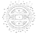
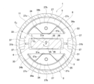
- FIG. 1 is an end view of a reverse input cutoff clutch according to a first example of an embodiment of the present disclosure, viewed from the input member side in the axial direction.
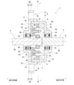
- FIG. 2 is a sectional view taken along line AA in FIG.
- FIG. 3 is a sectional view taken along line BB in FIG.
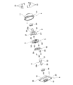
- FIG. 4 is an exploded perspective view of the reverse input cutoff clutch of the first example, with the torsion coil spring omitted.
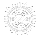
- FIG. 5 is a diagram similar to FIG. 3 in which the torsion coil spring and biasing member are omitted.
- FIG. 6 is a diagram similar to FIG. 5, omitting the torsion coil spring and the biasing member, and showing a state in which rotational torque is input to the input member.
- FIG. 5 is a diagram similar to FIG. 3 in which the torsion coil spring and biasing member are omitted.
- FIG. 6 is a diagram similar to FIG. 5, omitting the torsion coil spring and the biasing member, and
- FIG. 7 is a diagram similar to FIG. 5, omitting the torsion coil spring and the biasing member, and showing a state in which rotational torque is reversely input to the output member.
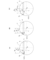
- FIGS. 8(A) to 8(C) are schematic diagrams for explaining the effects of regulating the dimensions and shapes of each part.
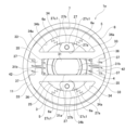
- FIG. 9 is a diagram similar to FIG. 3, showing a second example of the embodiment of the present disclosure.
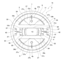
- FIG. 10 is a diagram similar to FIG. 3, showing a third example of the embodiment of the present disclosure.
- FIGS. 1 to 8(C) A first example of the embodiment of the present disclosure will be described using FIGS. 1 to 8(C).
- the axial direction, radial direction, and circumferential direction refer to the axial direction, radial direction, and circumferential direction of the reverse input cutoff clutch 1 unless otherwise specified.
- the axial direction, radial direction, and circumferential direction of the reverse input cutoff clutch 1 coincide with the axial direction, radial direction, and circumferential direction of the input member 3, and the axial direction, radial direction, and circumferential direction of the output member 4. Matches the circumferential direction.
- one side in the axial direction refers to the input member 3 side (the right side in FIG. 2), and the other side in the axial direction refers to the output member 4 side (the left side in FIG. 2).
- the reverse input cutoff clutch 1 of this example includes a pressed member 2, an input member 3, an output member 4, an engager 5, and a torsion coil spring 6.
- the reverse input cutoff clutch 1 transmits the rotational torque input to the input member 3 to the output member 4, whereas the rotational torque inputted in reverse to the output member 4 is completely blocked and transmitted to the input member 3. , or has a reverse input cutoff function that transmits only a part of it to the input member 3 and cuts off the rest.
- the pressed member 2 has a pressed surface 7 on its inner peripheral surface.
- the input-side engaging portion 27 of the input member 3 and the output-side engaging portion 31 of the output member 4 are coaxially disposed inside the pressed surface 7 in the radial direction, and the engager 5 is disposed in the distance direction with respect to the pressed surface 7. is arranged to allow for movement.
- the input side engaging portion 27, the output side engaging portion 31, and the engaging element 5 are rotatable on the radially inner side of the pressed surface 7. Further, the pressed surface 7 constitutes a surface that comes into contact with the pressing surface 33 of the engaging element 5 when the engaging element 5 moves in a direction approaching the pressed surface.
- the pressed surface 7 has an annular shape when viewed from the axial direction, and although it is not limited to this, in this example, it has a cylindrical shape with an inner diameter that does not change in the axial direction.
- the pressed member 2 is supported and fixed to a fixed part such as a housing that does not rotate even during use, and its rotation is restricted.
- the pressed member 2 is constituted by the fixed portion.
- the shape of the pressed member 2 is not limited as long as it has the pressed surface 7 on its inner peripheral surface.
- the pressed member 2 is configured by connecting and fixing a first element 8 disposed on one side in the axial direction and a second element 9 disposed on the other side in the axial direction using a plurality of coupling bolts 10.
- the entire structure is shaped like a hollow disk.
- the first element 8 includes a cylindrical first large-diameter tube portion 11 , a cylindrical first small-diameter tube portion 12 , a hollow circular flat plate-shaped first side plate portion 13 , and a flange portion 14 .
- the pressed surface 7 is provided on the inner circumferential surface of the first large-diameter cylindrical portion 11 and is constituted by a cylindrical surface centered on the central axis of the first element 8.
- the first large-diameter cylindrical portion 11 has an inner-diameter fitting surface 15 on the outer circumferential surface of the end portion on the other axial side, which is a portion located on the other axial side than the flange portion 14 .
- the inner diameter side fitting surface 15 is constituted by a cylindrical surface centered on the central axis of the first element 8.
- the first small-diameter cylindrical portion 12 is disposed on one side of the first large-diameter cylindrical portion 11 in the axial direction and coaxially with the first large-diameter cylindrical portion 11 .
- the first small diameter cylindrical portion 12 has a first bearing fitting surface 16 in a portion of the inner circumferential surface from the other end in the axial direction to the intermediate portion.
- the first bearing fitting surface 16 is constituted by a cylindrical surface centered on the central axis of the first element 8. That is, the pressed surface 7, the inner diameter side fitting surface 15, and the first bearing fitting surface 16 are arranged coaxially with each other.
- the first side plate part 13 has a hollow circular end face shape when viewed from the axial direction, and has an end on one side in the axial direction of the first large diameter cylinder part 11 and an end on the other side in the axial direction of the first small diameter cylinder part 12. Connect with. That is, the radially outer end of the first side plate part 13 is connected to one end in the axial direction of the first large diameter cylinder part 11, and the radially inner end of the first side plate part 13 is connected to the first large diameter cylinder part 11. It is connected to the other end of the small diameter cylindrical portion 12 in the axial direction.
- the flange portion 14 protrudes radially outward from the axially intermediate portion of the first large-diameter cylindrical portion 11 .
- the flange portion 14 has through holes penetrating in the axial direction at multiple locations in the circumferential direction. In this example, the flange portion 14 has through holes penetrating in the axial direction at eight locations in the circumferential direction.
- the second element 9 includes a cylindrical second large-diameter tube portion 17 , a cylindrical second small-diameter tube portion 18 , a hollow circular plate-shaped second side plate portion 19 , and a plurality of attachment portions 20 .
- the second large-diameter cylindrical portion 17 has an outer-diameter fitting surface 21 on the inner circumferential surface of one axial portion.
- the outer diameter side fitting surface 21 is constituted by a cylindrical surface centered on the central axis of the second element 9.
- the outer diameter side fitting surface 21 has an inner diameter dimension that allows it to be fitted to the inner diameter side fitting surface 15 of the first element 8 without rattling.
- the second large-diameter cylindrical portion 17 has screw holes opening on one end surface in the axial direction at multiple locations in the circumferential direction that align with the through holes of the first element 8. More specifically, the second large-diameter cylindrical portion 17 has screw holes opening at one end surface in the axial direction at eight locations in the circumferential direction that align with eight through holes provided in the first element 8 .
- the second small-diameter cylindrical portion 18 is arranged coaxially with the second large-diameter cylindrical portion 17 on the other axial side of the second large-diameter cylindrical portion 17 .
- the second small-diameter cylindrical portion 18 has a second bearing fitting surface 22 in a portion of the inner circumferential surface from one end in the axial direction to the intermediate portion.
- the second bearing fitting surface 22 is constituted by a cylindrical surface centered on the central axis of the second element 9. That is, the outer diameter side fitting surface 21 and the second bearing fitting surface 22 are arranged coaxially with each other.
- the second side plate part 19 has a hollow circular end face shape when viewed from the axial direction, and has an end on the other axial side of the second large diameter cylindrical part 17 and an end on one side in the axial direction of the second small diameter cylindrical part 18. Connect with. That is, the radially outer end of the second side plate portion 19 is connected to the other axial end of the second large diameter cylinder portion 17, and the radially inner end of the second side plate portion 19 is connected to the second large diameter cylinder portion 17. 2 is connected to one end of the small diameter cylindrical portion 18 in the axial direction.
- Each mounting portion 20 is provided at multiple locations in the circumferential direction.
- four attachment parts 20 are provided at equal intervals in the circumferential direction.
- the attachment portion 20 has a protrusion 23 that protrudes radially outward from the outer circumferential surface of the second large-diameter cylindrical portion 17, and an attachment hole 24 that passes through the protrusion 23 in the axial direction.
- the first element 8 and the second element 9 are such that the inner diameter side fitting surface 15 of the first element 8 is fitted to the outer diameter side fitting surface 21 of the second element 9 without play, and With the other axial side surface of the flange portion 14 of the element 8 in contact with one axial end surface of the second large diameter cylindrical portion 17 of the second element 9, the passage provided in the first element 8 is opened.
- the coupling bolt 10 inserted through the hole is screwed into a screw hole provided in the second element 9, and is further tightened to be coupled and fixed.
- the inner diameter side fitting surface 15 of the first element 8 and the first bearing fitting surface 16 are arranged coaxially with each other, and the outer diameter side fitting surface 21 of the second element 9 and the second bearing fitting surface are arranged coaxially with each other.
- the mating surfaces 22 are arranged coaxially with each other. Therefore, in the assembled state of the pressed member 2 in which the inner diameter side fitting surface 15 and the outer diameter side fitting surface 21 are fitted without play, the first bearing fitting surface 16 and the second bearing fitting surface 16 are fitted together without any play.
- the surfaces 22 are arranged coaxially with each other.
- the input member 3 has an input-side engaging portion 27 arranged radially inside the pressed surface 7 and is arranged coaxially with the pressed surface 7 .
- the input member 3 is connected to an input side mechanism such as an electric motor, receives rotational torque, and is configured to be rotatable on the radially inner side of the pressed surface 7 by the input of the rotational torque.
- the input-side engaging portion 27 is provided at a portion radially outward from the rotation center O of the input member 3 and is arranged at a position where it can engage with the input-side engaged portion 34 of the engager 5 .
- the input-side engaging portion 27 is configured to engage with the input-side engaged portion 34 as the input member 3 or the engager 5 rotates.
- the input member 3 includes a substrate portion 25 and an input shaft portion 26 in addition to the input side engaging portion 27.
- the substrate portion 25 has a substantially circular end face shape when viewed from the axial direction.
- the input shaft portion 26 protrudes from the center of one axial side surface of the substrate portion 25 toward one side in the axial direction.
- the input shaft portion 26 has a shank portion 28a on one side in the axial direction for connection to the output portion of the input side mechanism so as to be capable of transmitting torque.
- the shank portion 28a has a width across flat shape including two mutually parallel flat surfaces on the outer peripheral surface.
- the shank portion may have any shape as long as it can be connected to the output portion of the input mechanism in a torque transmittable manner.
- the input-side engaging portion 27 protrudes toward the other axial side from a portion of the other axial side surface of the base plate portion 25 that is radially outward from the rotation center O.
- the shape of the input-side engaging portion 27 is not limited as long as it is configured to engage with the input-side engaged portion 34. Further, the number of input-side engaging portions 27 is determined according to the number of engaging elements 5, and when the engaging element 5 is constituted by a plurality of engaging elements 5, the input-side engaging portion 27 also includes a plurality of input-side engaging elements. It is constituted by a joining part 27. Note that, depending on the shapes of the input-side engaging portion 27 and the input-side engaged portion 34, a plurality of input-side engaging portions 27 may be provided for each engager 5.
- the engager 5 is composed of two engagers 5. Therefore, the input-side engaging portion 27 is composed of two input-side engaging portions 27 in accordance with the number of the engaging elements 5.
- the two input-side engaging portions 27 are arranged at two positions on radially opposite sides of the other axial side surface of the substrate portion 25 and are spaced apart from each other in the radial direction of the input member 3 .
- each input-side engaging portion 27 has a symmetrical shape in the circumferential direction.
- each of the input-side engaging portions 27 has a substantially fan-shaped or substantially trapezoidal end surface shape, with the circumferential width increasing toward the radial outside when viewed from the axial direction.
- the radial inner surface 27a of each input-side engaging portion 27 is formed of a mutually parallel flat surface, and the radial outer surface 27b of each input-side engaging portion 27 is formed from the outer periphery of the base plate portion 25. It has the same cylindrical contour shape as the surface.
- the two circumferential side surfaces 27c of each input-side engaging portion 27 are formed of flat surfaces that are inclined in a direction that moves away from each other toward the outside in the radial direction.
- the input member 3 can be rotatably supported by the pressed member 2 or the fixed portion. In this example, it is rotatably supported inside the first element 8 of the pressed member 2 in the radial direction. Therefore, the first bearing 29 is disposed between the outer circumferential surface of the other axial side portion of the input shaft portion 26 and the first bearing fitting surface 16 of the first element 8 .
- the output member 4 has an output side engagement part 31 arranged radially inside the input side engagement part 27 on the radially inner side of the pressed surface 7, and is arranged coaxially with the pressed surface 7. . That is, the output member 4 is also arranged coaxially with the input member 3.
- the output member 4 is connected to an output side mechanism such as a speed reduction mechanism, and is configured to output rotational torque to the output side mechanism as the output member 4 rotates.
- the output-side engaging portion 31 is radially inner than the input-side engaging portion 27, but has a portion deviated radially outward from the rotation center O of the output member 4, and this portion is radially inner than the input-side engaging portion 27. It is arranged at a position where it can engage with the output side engaged portion 35.
- the output-side engaging portion 31 is configured such that the portion thereof engages with the output-side engaged portion 35 as the output member 4 or the engager 5 rotates.
- the output member 4 includes an output shaft portion 30 in addition to the output side engagement portion 31.
- the output shaft section 30 has a flange section 32 that protrudes radially outward at one end in the axial direction, and is capable of transmitting torque to the input section of the output side mechanism at the other end in the axial direction. It has a shank portion 28b for connection.
- the shank portion 28b has a width across flat shape including two mutually parallel flat surfaces on the outer peripheral surface. However, the shank portion can have any shape as long as it can be connected to the input portion of the output side mechanism so as to transmit torque.
- the shape of the output-side engaging portion 31 is not limited as long as it is configured to have a portion that engages with the output-side engaged portion 35. Further, the number of parts of the output side engaging part 31 that engage with the output side engaged part 35 is determined according to the number of the engaging elements 5, and the engaging element 5 is constituted by a plurality of engaging elements 5. In this case, the output-side engaging portion 31 is also configured to have a plurality of engaging portions. Note that, depending on the shapes of the output-side engaging portion 31 and the output-side engaged portion 35, each engager 5 may have a plurality of output-side engaging portions 31 or a plurality of output-side engaged portions 35. An engaging portion may also be provided.
- the output side engaging portion 31 is configured to have a portion that engages with two output side engaged portions 35 in accordance with the number of engaging elements 5.
- the output-side engaging portion 31 has a substantially rectangular or substantially elliptical end surface shape when viewed from the axial direction, and extends from the center of the end surface of the output shaft portion 30 on one side in the axial direction toward one side in the axial direction. It stands out. That is, the distance from the rotation center O of the output member 4 to the outer peripheral surface of the output side engaging portion 31, which is the portion that engages with the output side engaged portion 35, is not constant in the circumferential direction. Therefore, the output side engaging portion 31 has a cam function.
- the outer circumferential surface of the output side engaging portion 31 is composed of two mutually parallel flat surfaces 31a and two convex curved surfaces 31b each having a partially cylindrical shape. Therefore, the distance from the rotation center O of the output member 4 to the outer peripheral surface of the output side engaging portion 31 is not constant over the circumferential direction.
- Each of the two convex curved surfaces 31b is constituted by a partial cylindrical surface centered on the rotation center O of the output member 4.
- the output side engaging portion 31 is plane symmetrical with respect to a virtual plane passing through the rotation center O of the output member 4 and orthogonal to the flat surface 31a. Further, the output side engaging portion 31 is plane symmetrical with respect to a virtual plane passing through the rotation center O of the output member 4 and parallel to the flat surface 31a.
- Such an output-side engaging portion 31 is arranged between the two input-side engaging portions 27.
- the output member 4 can be rotatably supported by the pressed member 2 or the fixed portion.
- the output member 4 is rotatably supported inside the second element 9 of the pressed member 2 in the radial direction. Therefore, the second bearing 44 is disposed between the outer circumferential surface of one side of the output shaft portion 30 in the axial direction and the second bearing fitting surface 22 of the second element 9.
- the engager 5 includes a pressing surface 33 facing the pressed surface 7 , an input-side engaged portion 34 that can engage with the input-side engaging portion 27 , and an output side that can engage with the output-side engaging portion 31 . It has an engaged portion 35 and is arranged so as to be movable in a first direction, which is a direction toward and away from the pressed surface 7 .
- the engager 5 When rotational torque is input to the input member 3, the engager 5 separates from the pressed surface 7 in the first direction based on the engagement of the input side engaging portion 27 with the input side engaged portion 34. By moving in the direction and engaging the output side engaged portion 35 with the output side engaging portion 31, the rotational torque input to the input member 3 is transmitted to the output member 4, and the rotational torque is transmitted to the output member 4.
- the pressing surface 33 When the torque is reversely input, the pressing surface 33 is pressed against the pressed surface 7 based on the engagement of the output side engaging part 31 with the output side engaged part 35, and the pressing surface 33 is pressed against the pressed surface. 7 to be frictionally engaged.
- the engaging element 5 can be composed of one engaging element 5 having such a configuration, or can be composed of two or more engaging elements 5.
- the engaging element 5 is composed of two engaging elements 5. Each engaging element 5 has a function as an engaging element 5. Each engaging element 5 has a substantially semicircular end face shape when viewed from the axial direction, and has a symmetrical shape in the width direction (direction indicated by arrow B in FIG. 5). Hereinafter, the configuration of each engaging element 5 will be explained.
- the radial direction with respect to the engager 5 is the distance direction of the pressing surface 33 with respect to the pressed surface 7, and corresponds to the direction shown by arrow A in FIG.
- the width direction is a direction perpendicular to both the distance direction of the pressing surface 33 with respect to the pressed surface 7 and the axial direction of the input member 3, and corresponds to the direction shown by arrow B in FIG.
- the radial direction regarding the engager 5 corresponds to the first direction
- the width direction regarding the engager 5 corresponds to the second direction.
- the pressing surface 33 is provided on the radially outer surface of the engager 5 that faces the pressed surface 7 .
- the pressing surfaces 33 are configured by two pressing surfaces 33 provided at two positions spaced apart from each other in the circumferential direction on the radially outer surface of the engager 5.
- Each pressing surface 33 is constituted by a partially cylindrical convex curved surface having a radius of curvature smaller than the radius of curvature of the pressed surface 7 .
- a portion of the radially outer surface of the engager 5 that is circumferentially removed from the two pressing surfaces 33 is centered on the central axis O of the input member 3 and located between the two pressing surfaces 33 when viewed from the axial direction. It exists radially inside of the virtual circle that is in contact with 33. That is, in a state in which the two pressing surfaces 33 are in contact with the pressed surface 7 , the portions that are removed from the two pressing surfaces 33 in the circumferential direction do not contact the pressed surface 7 .
- the pressing surface 33 has a surface texture that has a larger coefficient of friction with respect to the pressed surface 7 than other parts of the engager 5. Further, the pressing surface 33 can be constructed integrally with other parts of the engaging element 5, or can be constructed from the surface of a friction material fixed to other parts of the engaging element 5 by pasting, adhesive, etc. You can also do it.
- the input side engaged portion 34 is provided at a radially intermediate portion of the widthwise center portion of the engager 5. More specifically, although not limited thereto, the input side engaged portion 34 has a substantially arcuate opening shape when viewed from the axial direction, and has a radially intermediate portion at the widthwise center position of the engager 5. It is composed of a through hole that penetrates in the axial direction.
- the input side engaged portion 34 has a size that allows the input side engaging portion 27 to be inserted loosely. Therefore, when the input-side engaging portion 27 is inserted inside the input-side engaged portion 34, there is no space between the input-side engaging portion 27 and the inner surface of the input-side engaged portion 34 of the engager 5. There are gaps in both the width direction and the radial direction. Therefore, the input side engaged portion 27 can be displaced relative to the input side engaged portion 34 in the rotational direction of the input member 3, and the input side engaged portion 34 can be displaced relative to the input side engaged portion 27. On the other hand, the engager 5 can be displaced in the radial direction.
- the shape of the input-side engaged portion 34 is not limited as long as it is configured to be able to engage with the input-side engaging portion 27.
- the input side engaged portion 34 is a flat surface provided on a radially inner surface of the engager 5 on a surface facing radially outward, and parallel to the flat surface portion 36. 34a, and a partially cylindrical concave curved surface 34b on the surface facing inward in the radial direction.
- the input side engaged portion 34 may be a bottomed hole that opens only on one side surface in the axial direction of the engager 5, or the input side engaged portion 34 may be formed as an open hole on the outer side surface in the radial direction of the engager 5. It can also be configured with a cutout.
- the output side engaged portion 35 is provided at the widthwise center portion of the radially inner surface of the engager 5.
- the shape of the output-side engaged portion 35 is not limited as long as it is configured to be able to engage with the output-side engaging portion 31.
- the engager 5 has a flat surface portion 36 on the radially inner surface, and has two convex portions 37 that protrude radially inward at two positions in the width direction of the flat surface portion 36.
- the output side engaged portion 35 is constituted by a portion of the flat surface portion 36 that exists between the two convex portions 37 in the width direction.
- the width direction dimension of the output side engaged portion 35 that is, the interval between the two convex portions 37, is larger than the width direction dimension of the flat surface 31a of the output side engagement portion 31.
- the pressing surfaces 33 of the two engagers 5 are radially opposite to each other, and the flat surface portions 36 are opposed to each other, and each engager 5 is pressed.
- the engaging elements 5 are arranged inside the member 2 in the radial direction so as to be movable in a first direction corresponding to the distance direction of the pressing surface 33 relative to the pressed surface 7 .
- the two input side engaging parts 27 of the input member 3 arranged on one side in the axial direction are inserted into the input side engaged parts 34 of the two engagers 5 in the axial direction, and the other side in the axial direction
- the output-side engaging portion 31 of the output member 4 disposed in is inserted in the axial direction between the output-side engaged portions 35 of the two engagers 5. That is, the two engagers 5 are arranged such that the output side engaged portion 31 is sandwiched between the respective output side engaged portions 35 from the outside in the radial direction.
- the portion between the pressed surface 7 and the two pressing surfaces 33 and the two convex portions 37 of the two engagers face each other.
- the inner diameter dimension of the pressed member 2 and the radial dimension of the engager 5 are adjusted such that a gap exists in at least one of the portions between the respective tip surfaces of the two combinations of convex portions 37 constructed by regulated.
- the torsion coil spring 6 is provided between the input-side engaging portion 27 of the input member 3 and the engager 5, generates elasticity including a component related to the first direction, and adjusts the input-side engagement based on the elasticity.
- the portion 27 is provided with a resistance force against relative rotation of the input side engaging portion 27 with respect to the engager 5.
- the torsion coil spring 6 is configured to It is composed of two torsion coil springs 6.
- the torsion coil spring 6 is arranged between the input side engaging part 27 of the input member 3 and the input side engaged part 34 of the engaging element 5, and Two torsion coil springs 6 are provided for each combination of the side engaging portion 27 and the input side engaged portion 34.
- each of the two torsion coil springs 6 is held between the circumferential side surface 27c of the input side engaging portion 27 and the flat surface 34a of the input side engaged portion 34. That is, the two torsion coil springs 6 are arranged in a direction that the more they go inward in the radial direction of the engager 5, which is the first direction, the farther apart they are from each other in the width direction of the engager 5, which is the second direction. Therefore, the directions of the components of the elasticity of the two torsion coil springs 6 in the second direction are opposite to each other.
- the torsion coil spring 6 is constituted by a compression coil spring. That is, the torsion coil spring 6 is held between the input side engaging portion 27 and the input side engaged portion 34 in an elastically compressed state. Therefore, the direction of the component of the force applied to the engager 5 in the first direction based on the elasticity of the torsion coil spring 6 moves the engager 5 in a direction that moves the pressing surface 33 of the engager 5 away from the pressed surface 7. In other words, the engaging element 5 is moved inward in the radial direction.
- the input side engaging part 27 tries to rotate inside the input side engaged part 34 as the input member 3 rotates, the input side engages with respect to the rotational direction of the input member 3 of the two torsion coil springs.
- a resistance force is applied to the input side engaging portion 27 from the torsion coil spring 6 disposed on the front side of the joint portion 27 .
- the reverse input cutoff clutch 1 of this example includes a biasing member 42 and a support member 45 as optional components.
- the biasing member 42 has a function of elastically biasing the engager 5 radially outward.
- the biasing member 42 is provided between the radially inner surfaces of the two engaging elements 5 in accordance with the arrangement of the two engaging elements 5. More specifically, in this example, the biasing member 42 is provided at two positions in the width direction between the flat surface portions 36 provided on the radially inner surfaces of the two engagers 5. It is constituted by a force member 42.
- the biasing member 42 is constituted by a compression coil spring, and is held between the flat surface portions 36 of the two engagers 5 in an elastically compressed state.
- the two engagers 5 are elastically urged by the urging member 42 in directions away from each other in the first direction. Thereby, in the neutral state where no torque is applied to either the input member 3 or the output member 4, the pressing surfaces 33 of the two engaging elements 5 are brought into contact with the pressed surface 7.
- Each of the two biasing members 42 is formed by inserting the respective protrusions 37 inside the ends on both sides in the longitudinal direction between the two combinations of the protrusions 37 of the two engagers 5. , are placed in such a way that they are prevented from falling off.
- the radially outward force applied to the engager 5 by the biasing member 42 is greater than the radially inward force applied to the engager 5 based on the elasticity of the torsion coil spring 6.
- the elasticity of each biasing member 42 and the elasticity of each torsion coil spring 6 are regulated so as to increase.
- the support member 45 extends between the tip portions of the two input side engaging portions 27 of the input member 3, which are the ends on the other side in the axial direction.
- the support member 45 has a substantially oval or substantially rectangular end face shape when viewed from the axial direction.
- the support member 45 has a large-diameter through hole 38 in the center thereof through which the output-side engaging portion 31 of the output member 4 is inserted, and has a large-diameter through hole 38 on the opposite side 2 across the large-diameter through hole 38 in the longitudinal direction.
- Small diameter through holes 39 are provided at certain locations.
- the support member 45 has two inputs by screwing a support bolt 40 inserted through each small-diameter through hole 39 into a threaded hole 41 opened at the other end surface in the axial direction of each input side engaging portion 27. It is supported and fixed to the side engaging portion 27.
- FIGS. 6 and 7 show exaggerated gaps in the radial direction between the input member 3 and the output member 4, and the two engagers 5.
- the two engagers 5 move in a direction away from the pressed surface 7, regardless of the rotation direction of the input member 3. More specifically, as shown in FIG. 6, the input-side engaging portion 27 selects one of the two torsion coil springs 6 disposed on both sides of the input-side engaging portion 27 in the second direction.
- the torsion coil spring 6 arranged on the front side is elastically moved against the resistance force applied to the input side engagement part 27 from the torsion coil spring 6 arranged on the front side of the input side engagement part 27 in the rotation direction. While being compressed, the input member 3 is rotated in the rotational direction (counterclockwise in the example of FIG. 6) inside the input side engaged portion 34.
- the gap between the radially inner surface 27a of the input side engaging portion 27 and the flat surface 34a of the input side engaged portion 34 is reduced, and the radially inner surface 27a of the input side engaging portion 27 is input. It is brought into contact with the flat surface 34a of the side engaged portion 34.
- the flat surface 34a is pressed radially inward by the radially inner surface 27a, and the engager 5 moves in a direction away from the pressed surface 7. That is, the two engagers 5 move radially inward, which is the direction in which they approach each other, based on their engagement with the input member 3, so that the radially inner surfaces of the two engagers 5 approach each other, and the two The output side engaged portion 31 of the output member 4 is held between the output side engaged portion 35 of the engager 5 from both sides in the radial direction.
- the two engagers 5 move in a direction approaching the pressed surface 7, regardless of the rotation direction of the output member 3. More specifically, as shown in FIG. 7, the output-side engaging portion 31 is located inside the output-side engaged portions 35 of the two engagers 5 in the rotational direction of the output member 4 (the example of FIG. (clockwise). Output side engaged portion 35 is pressed radially outward by the connecting portion (corner portion) between flat surface 31 a and convex curved surface 31 b on the outer circumferential surface of output side engaging portion 31 , and the two engagers 5 moves in a direction approaching the pressed surface 7.
- the two engagers 5 move radially outward in the direction away from each other based on the engagement with the output member 4, and the pressing surfaces 33 of the two engagers 5 contact the pressed surface 7. It contacts and frictionally engages with the pressed surface 7.
- the pressing surface 33 of the engager 5 should not slide (relative rotation) with respect to the pressed surface 7. In this way, the engaging member 5 is stretched (pinched) between the output-side engaging portion 31 and the pressed member 2, and the output member 4 is locked.
- the pressing surface 33 of the engager 5 should slide against the pressed surface 7.
- the engaging member 5 is stretched (pinched) between the output side engaging portion 31 and the pressed member 2 so as to move, and the output member 4 is semi-locked.
- the size of the gap between each component is adjusted so that the above operation is possible.
- the positional relationship in which the pressing surfaces 33 of the two engagers 5 are in contact with the pressed surface 7 there is Based on the fact that the corner of the output-side engaging portion 31 presses the output-side engaged portion 35, a gap exists that allows the pressing surface 33 to be further pressed toward the pressed surface 7.
- each part of the pressed member 2, input member 3, output member 4, and engagement member 5 are further regulated so as to satisfy the following relationship. Note that in FIGS. 5 to 7, the dimension in the long axis direction of the output side engaging portion 31 is exaggerated with respect to the dimension in the short axis direction.
- the two pressing surfaces 33 are pressed against the pressed surface 7, and the input member 3 rotates in a direction opposite to the predetermined direction (for example, in the clockwise direction in FIG. 5). (counterclockwise), the input-side engaging portion 27 and the input-side engaged portion 34 engaged (a part of the input-side engaging portion 27 came into contact with the input-side engaged portion 34).
- the first distance D1 which is the distance in the second direction between the contact portion P in between the input side engaging portion 27 and the input side engaged portion 34 and the rotation center O of the input member 3, is It is made smaller than the second distance D2, which is the distance in the second direction between the contact portion P out between the output side engaging portion 31 and the output side engaged portion 35 and the rotation center O of the output member 4 ( D 1 ⁇ D 2 ).
- the axial dimension can be shortened and the number of parts can be reduced for the same reason as the reverse input cutoff clutch described in International Publication No. 2019/026794.
- the reverse input cutoff clutch 1 of this example converts the respective rotations of the input member 3 and the output member 4 into radial movement of the engager 5.
- the engager 5 can be engaged with the output member 4 located on the radially inner side of the engager 5.
- the engaging element 5 is pressed against the pressed member 2 located on the radially outer side of the engaging element 5.
- the reverse input cutoff clutch 1 of this example is configured to transfer rotational torque from the input member 3 to the output member 4 based on the radial movement of the engager 5 controlled by the rotation of the input member 3 and/or the output member 4. Since it is possible to switch between an unlocked state of the output member 4 in which transmission is possible and a locked state in which rotation of the output member 4 is prevented or a semi-locked state in which rotation of the output member 4 is suppressed, the reverse input cutoff clutch 1 The axial dimension of the entire device can be shortened.
- the engager 5 has both the function of transmitting the rotational torque input to the input member 3 to the output member 4 and the function of locking or semi-locking the output member 4. Therefore, the number of parts of the reverse input cutoff clutch 1 can be reduced, and the operation is more stable than when separate members have the function of transmitting rotational torque and the function of locking or semi-locking. be able to.
- the direction of the force acting on the engagement element 5 from the input member 3 and the direction of the force acting on the engagement element 5 from the output member 4 are opposite, the magnitude relationship between both forces can be regulated. , the moving direction of the engager 5 can be controlled. Therefore, the operation of switching the output member 4 between the locked state or half-locked state and the unlocked state can be performed stably and reliably.
- the torsion coil spring 6 which is disposed in front of the input side engaging portion 27 with respect to the rotational direction of the input member 3 is selected from among the two torsion coil springs 6. 6 needs to be elastically compressed against the resistance force applied from the torsion coil spring 6 to the input side engaging portion 27. Therefore, even if a certain amount of clearance is secured between the input-side engaging portion 27 and the input-side engaged portion 34 in order to ensure workability in assembling the reverse input cutoff clutch 1, the input member 3 may be loose. It is possible to suppress the stickiness.
- the elasticity of the torsion coil spring 6 includes a component related to the second direction in addition to a component related to the first direction.
- the directions of the components of the elasticity of the two torsion coil springs 6 in the second direction are opposite to each other.
- the two torsion coil springs 6 have the same spring characteristics such as spring constant and free length. Therefore, in a neutral state where no torque is applied to either the input member 3 or the output member 4, the input side engaging portion 27 can be positioned at the center position of the input side engaged portion 34 with respect to the second direction. I can do it.
- the gap in the circumferential direction between the input side engaging portion 27 and the input side engaged portion 34 can be made the same. Therefore, when the direction of the rotational torque input to the input member 3 is reversed, the circumferential gap between the input side engaging portion 27 and the input side engaged portion 34 can be prevented from increasing. It is possible to prevent rattling of the input member 3 from increasing.
- the input side engaging portions that engage with each other and the input It is also possible to make the spring characteristics of the two torsion coil springs disposed between the side engaged portions different from each other.
- the circumference between the input-side engaging part and the input-side engaged part is reduced in a neutral state where no torque is applied to either the input member or the output member.
- the gap that exists on the front side when the input member rotates in one direction can be made smaller than the gap that exists on the front side when the input member rotates in the other direction. Therefore, responsiveness when the input member rotates in one direction can be improved.
- the engaging member 42 elastically urges the engaging element 5 toward the outside in the radial direction, so that the pressing surface 33 of the engaging element 5 is pressed against the pressed surface 7 in the neutral state. I'm trying to get in touch with. Therefore, when rotational torque is reversely input to the output member 4, the rotation of the output member 4 can be immediately locked or semi-locked.
- the support member 45 is provided so as to extend between the tips of the two input side engaging portions 27 provided on the input member 3. Therefore, even if a radially outward force is applied from the engager 5 to the input side engaging portion 27 when switching the reverse input cutoff clutch 1 from the locked or half-locked state to the unlocked state, the two It is possible to prevent the input-side engaging portions 27 from being deformed so as to separate from each other.
- a first The distance D 1 is greater than the second distance D 2 which is the distance between the contact portion P out between the output side engaging portion 31 and the output side engaged portion 35 and the rotation center O of the output member 4 in the second direction.
- the contact portion C1 between the output side engaging portion 31 and the output side engaged portion 35 is the contact portion C2 between the pressing surface 33 and the pressed surface 7 .
- the input member 3 is When rotational torque is input, the engager 5 tends to rotate clockwise around the contact portion C1 .
- the side of the two pressing surfaces 33 that is closer to the contact portion C1 than the rotation center O of the output member 4 in the second direction (FIG. 8(C)
- the pressing surface 33 located on the left side of C) tends to be strongly pressed against the pressed surface 7 and bite into it.
- the first distance D 1 is smaller than the second distance D 2 (D 1 ⁇ D 2 ), and the contact portion C 1 is further away from the virtual straight line L in the first direction.
- the output member 4 is located on the side closer to the rotation center O of the output member 4, as shown in FIG . It tends to rotate clockwise around the center.
- the first element 8 having the pressed surface 7 and the second element 9 having the mounting part 20 supported and fixed to the fixed part are constructed separately. That is, the first element 8 having the pressed surface 7 is not directly fixed to the fixed part by bolting. For this reason, the pressed member 2 is supported and fixed to the fixed part by screwing the support bolts inserted through the respective mounting holes 24 of the second element 9 into the respective screw holes of the fixed part and further tightening them. Accordingly, deformation of the first element 8 can be prevented.
- an inner diameter side fitting surface 15 provided on the outer circumferential surface of the first large diameter cylindrical portion 11 of the first element 8 and an inner circumferential surface of the second large diameter cylindrical portion 17 of the second element 9 are provided.
- the outer diameter side fitting surface 21 is fitted without play. Therefore, even if the pressed surface 7 is pressed radially outward by the pressing surface 33 of each engager 5 due to the reverse input of rotational torque to the output member 4, the pressed surface 7 is Deformation toward the outside can be prevented.
- a reinforcing rib 43 can also be provided. By providing the reinforcing ribs 43, deformation of the pressed surface 7 can be more effectively prevented.
- a hardened layer is formed by induction hardening only on the pressed surface 7 and its vicinity of the inner circumferential surface of the first large-diameter cylindrical portion 11, and then polished.
- the hardness of the pressed surface 7 is ensured, and the dimensional accuracy and roundness of the pressed surface 7 are ensured favorably.
- the reverse input cutoff clutch 1 can be smoothly switched from an unlocked state to a locked state or a semi-locked state.
- the input member 3 is rotatably supported with respect to a first element 8 having a pressed surface 7
- the output member 4 is rotatably supported with respect to a second element 9 having a mounting portion 20.
- the input member is supported rotatably with respect to a second element having a mounting portion supported and fixed to a fixed portion
- the output member is supported with respect to a first element having a pressed surface. It can also be supported rotatably.
- the pressed surface and the attachment portion can be provided in the same element.
- the torsion coil spring 6 is composed of a compression coil spring, but it can also be composed of a tension coil spring.
- the direction of the component of the force applied to the engager 5 in the first direction based on the elasticity of the torsion coil spring 6 is such that the engager 5 is moved in a direction that brings the pressing surface 33 of the engager 5 closer to the pressed surface 7. This is the direction of movement, that is, the direction of movement of the engager 5 radially outward. Therefore, even if the biasing member 42 is omitted, the pressing surface 33 of the engager 5 can be brought into contact with the pressed surface 7 in the neutral state.
- the materials of the input member, the output member, the pressed member, and the engager are not particularly limited.
- these materials may include metals such as iron alloys, copper alloys, and aluminum alloys, as well as synthetic resins mixed with reinforcing fibers as needed.
- the same material or different materials can be applied to each of the input member, output member, pressed member, and engagement element.
- the input member, the output member, the pressed member, and the engager come into contact with each other as long as the conditions for the output member to lock or semi-lock when a rotational torque is reversely input to the output member are satisfied.
- a lubricant can also be interposed in the portion where the material is removed.
- at least one of the input member, the output member, the pressed member, and the engager may be made of oil-impregnated metal.
- the torsion coil spring 6a is constituted by a compression coil spring, and the direction of the component of the force applied to the engager 5 in the first direction is determined based on the elasticity of the torsion coil spring 6a. , the engaging element 5 is moved in a direction in which the pressing surface 33 of the engaging element 5 approaches the pressed surface 7, that is, the engaging element 5 is moved radially outward.
- the input-side engaging portion 27 of the input member 3 has a substantially trapezoidal end face shape whose circumferential width decreases as it goes radially outward when viewed from the axial direction. That is, the two circumferential side surfaces 27c1 of the input-side engaging portion 27 are formed of flat surfaces that are inclined in a direction that approaches each other as they go radially outward.
- the torsion coil spring 6a is stretched between the circumferential side surface 27c1 of the input side engaging portion 27 and the concave curved surface 34b of the input side engaged portion 34.
- the torsion coil spring 6a is composed of two torsion coil springs 6a.
- the two torsion coil springs 6a are arranged in such a direction that they approach each other as they go inward in the radial direction of the engager 5. Therefore, the direction of the component in the first direction of the force applied to the engager 5 based on the elasticity of the two torsion coil springs 6a is directed in the direction that brings the respective pressing surfaces 33 of the engager 5 closer to the pressed surface 7. This is the direction in which the engaging element 5 is moved, that is, the direction in which the engaging element 5 is moved radially outward.
- the directions of the components of the elasticity of the two torsion coil springs 6a in the second direction are opposite to each other. Therefore, when the input side engaging part 27 tries to rotate inside the input side engaged part 34 as the input member 3 rotates, the input side engaging part 27 is arranged on the front side of the input side engaging part 27 with respect to the rotational direction of the input member 3. A resistance force is applied to the input side engaging portion 27 from the torsion coil spring 6a.
- the direction of the component in the first direction of the force applied to the engager 5 based on the elasticity of the torsion coil spring 6a is changed to the direction in which the engager 5 is moved radially outward. It is said that Therefore, in addition to the biasing member 42, the engagement element 5 can be elastically biased radially outward by the elasticity of the torsion coil spring 6a. As a result, in the neutral state, the pressing surface 33 of the engager 5 can be brought into contact with the pressed surface 7, and when reverse rotational torque is input to the output member 4, the rotation of the output member 4 is immediately locked. Or it can be semi-locked.
- the biasing member 42 can also be omitted.
- the configuration and effects of other parts of the second example are the same as those of the first example.
- FIG. 10 A third example of the embodiment of the present disclosure will be described using FIG. 10.
- the torsion coil spring 6b is connected to the input side engaging portion 27 and the input side cover which are engaged with each other among the combinations of the two input side engaging portions 27 and the two engaging elements 5.
- Each combination with the engaging portion 34 is configured with one torsion coil spring 6b.
- the torsion coil spring 6b has a circumferentially central portion of a radially outer portion of the input side engaging portion 27 and a circumferentially central portion of a portion of the engager 5 that is located radially outwardly of the input side engaged portion 34. It is being passed on to. Specifically, the radially inner end of the torsion coil spring 6b is located at the circumferential center of the radially outer portion of the input side engaging portion 27, with the axis parallel to the central axis O of the input member 3 as the center. The radially outer end of the torsion coil spring 6b is located at the circumferential center of the portion of the engager 5 located on the radially outer side of the input side engaged portion 34. , are supported so as to be swingable about an axis parallel to the central axis O of the input member 3.
- the elasticity of the torsion coil spring 6b includes a component related to the first direction, but does not include a component related to the second direction. Further, the torsion coil spring 6b is constituted by a tension coil spring. Therefore, the direction of the component in the first direction of the force applied to the engager 5 based on the elasticity of the torsion coil spring 6b moves the engager 5 in a direction that moves the pressing surface 33 of the engager 5 away from the pressed surface 7. ie, the direction in which the engager 5 is moved radially inward.
- the reverse input cutoff clutch 1b of this example when the input side engaging portion 27 rotates inside the input side engaged portion 34 as the input member 3 rotates, the torsion coil spring 6b elastically expands. In this state, the torsion coil spring 6b tends to recover elastically, so that a resistance force is applied to the input side engaging portion 27 against rotation relative to the engager 5. Therefore, in the reverse input cutoff clutch 1b of this example, even if a certain amount of clearance is secured between the input side engaging portion 27 and the input side engaged portion 34 in order to ensure workability in assembly work, the input Shaking of the member 3 can be suppressed.
- one torsion coil spring is provided for each combination of the input side engaging portion 27 and the input side engaged portion 34 that engage with each other regardless of the rotational direction of the input member 3.
- 6b can provide a resistance force against the input-side engaging portion 27 attempting to rotate relative to the engager 5. That is, in comparison with the first example, the number of torsion coil springs 6b can be reduced.
- the configuration and effects of other parts of the third example are the same as those of the first example.
- the torsion coil spring 6 can also be constituted by a compression coil spring.
- the direction of the component of the force applied to the engager 5 in the first direction based on the elasticity of the torsion coil spring 6b is changed so that the engager 5 is moved in a direction that brings the pressing surface 33 of the engaging element 5 closer to the pressed surface 7.
- the direction of movement that is, the direction of movement of the engager 5 toward the outside in the radial direction can be made.
Landscapes
- Engineering & Computer Science (AREA)
- General Engineering & Computer Science (AREA)
- Mechanical Engineering (AREA)
- Braking Arrangements (AREA)
Priority Applications (1)
| Application Number | Priority Date | Filing Date | Title |
|---|---|---|---|
| JP2023541971A JP7375989B1 (ja) | 2022-05-30 | 2023-04-03 | 逆入力遮断クラッチ |
Applications Claiming Priority (2)
| Application Number | Priority Date | Filing Date | Title |
|---|---|---|---|
| JP2022087800 | 2022-05-30 | ||
| JP2022-087800 | 2022-05-30 |
Publications (1)
| Publication Number | Publication Date |
|---|---|
| WO2023233801A1 true WO2023233801A1 (ja) | 2023-12-07 |
Family
ID=89026210
Family Applications (1)
| Application Number | Title | Priority Date | Filing Date |
|---|---|---|---|
| PCT/JP2023/013802 Ceased WO2023233801A1 (ja) | 2022-05-30 | 2023-04-03 | 逆入力遮断クラッチ |
Country Status (2)
| Country | Link |
|---|---|
| JP (1) | JP7375989B1 (cg-RX-API-DMAC7.html) |
| WO (1) | WO2023233801A1 (cg-RX-API-DMAC7.html) |
Citations (3)
| Publication number | Priority date | Publication date | Assignee | Title |
|---|---|---|---|---|
| WO2019026794A1 (ja) * | 2017-08-01 | 2019-02-07 | 日本精工株式会社 | 逆入力遮断クラッチ、電動バルブタイミング調整装置、可変圧縮比装置、および電動パワーステアリング装置 |
| WO2019216280A1 (ja) * | 2018-05-07 | 2019-11-14 | 日本精工株式会社 | 逆入力遮断クラッチ及びアクチュエータ |
| WO2021054481A1 (ja) * | 2019-09-20 | 2021-03-25 | 日本精工株式会社 | 逆入力遮断クラッチ |
-
2023
- 2023-04-03 WO PCT/JP2023/013802 patent/WO2023233801A1/ja not_active Ceased
- 2023-04-03 JP JP2023541971A patent/JP7375989B1/ja active Active
Patent Citations (3)
| Publication number | Priority date | Publication date | Assignee | Title |
|---|---|---|---|---|
| WO2019026794A1 (ja) * | 2017-08-01 | 2019-02-07 | 日本精工株式会社 | 逆入力遮断クラッチ、電動バルブタイミング調整装置、可変圧縮比装置、および電動パワーステアリング装置 |
| WO2019216280A1 (ja) * | 2018-05-07 | 2019-11-14 | 日本精工株式会社 | 逆入力遮断クラッチ及びアクチュエータ |
| WO2021054481A1 (ja) * | 2019-09-20 | 2021-03-25 | 日本精工株式会社 | 逆入力遮断クラッチ |
Also Published As
| Publication number | Publication date |
|---|---|
| JPWO2023233801A1 (cg-RX-API-DMAC7.html) | 2023-12-07 |
| JP7375989B1 (ja) | 2023-11-08 |
Similar Documents
| Publication | Publication Date | Title |
|---|---|---|
| US10711851B2 (en) | Clutch unit | |
| US11708870B2 (en) | Reverse-input blocking clutch | |
| JP7375991B1 (ja) | 逆入力遮断クラッチおよびその組立方法 | |
| JP7509335B1 (ja) | 逆入力遮断クラッチ | |
| JP7243927B2 (ja) | 逆入力遮断クラッチ | |
| US20010017496A1 (en) | Clutch having reduced noise level and motor including such clutch | |
| JP2008157461A (ja) | 軸方向スペーサを備えた軸方向一方向クラッチ | |
| JP7375986B2 (ja) | 逆入力遮断クラッチ | |
| JP7375989B1 (ja) | 逆入力遮断クラッチ | |
| JP7396548B1 (ja) | 逆入力遮断クラッチ | |
| WO2022168466A1 (ja) | 逆入力遮断クラッチ | |
| US20260110343A1 (en) | Reverse-input blocking clutch | |
| JP2023018310A (ja) | 逆入力遮断クラッチ及びこれを備えるクラッチユニット | |
| JP2022126361A (ja) | 逆入力遮断クラッチ付電動モータ | |
| JP2023085990A (ja) | 逆入力遮断クラッチ | |
| JP2023175529A (ja) | 逆入力遮断クラッチ | |
| JP7831719B1 (ja) | 逆入力遮断クラッチ | |
| WO2026105540A1 (ja) | 逆入力遮断クラッチ | |
| JP2025125462A (ja) | 逆入力遮断クラッチ | |
| JP2022147480A (ja) | 逆入力遮断クラッチおよびこれを備えるクラッチユニット | |
| JP7643648B1 (ja) | 逆入力遮断クラッチおよびその組立方法 | |
| JP2023022882A (ja) | 逆入力遮断クラッチ | |
| JP2025125461A (ja) | 逆入力遮断クラッチ | |
| KR100439981B1 (ko) | 변속조작기구의 케이블 연결장치 | |
| TW202511632A (zh) | 逆輸入遮斷離合器及使用了該離合器的扭力限制器 |
Legal Events
| Date | Code | Title | Description |
|---|---|---|---|
| ENP | Entry into the national phase |
Ref document number: 2023541971 Country of ref document: JP Kind code of ref document: A |
|
| 121 | Ep: the epo has been informed by wipo that ep was designated in this application |
Ref document number: 23815563 Country of ref document: EP Kind code of ref document: A1 |
|
| NENP | Non-entry into the national phase |
Ref country code: DE |
|
| 122 | Ep: pct application non-entry in european phase |
Ref document number: 23815563 Country of ref document: EP Kind code of ref document: A1 |