WO2023233643A1 - レーダ装置 - Google Patents
レーダ装置 Download PDFInfo
- Publication number
- WO2023233643A1 WO2023233643A1 PCT/JP2022/022574 JP2022022574W WO2023233643A1 WO 2023233643 A1 WO2023233643 A1 WO 2023233643A1 JP 2022022574 W JP2022022574 W JP 2022022574W WO 2023233643 A1 WO2023233643 A1 WO 2023233643A1
- Authority
- WO
- WIPO (PCT)
- Prior art keywords
- radar device
- lprf
- hprf
- signal
- pulse
- Prior art date
- Legal status (The legal status is an assumption and is not a legal conclusion. Google has not performed a legal analysis and makes no representation as to the accuracy of the status listed.)
- Ceased
Links
Images









Classifications
-
- G—PHYSICS
- G01—MEASURING; TESTING
- G01S—RADIO DIRECTION-FINDING; RADIO NAVIGATION; DETERMINING DISTANCE OR VELOCITY BY USE OF RADIO WAVES; LOCATING OR PRESENCE-DETECTING BY USE OF THE REFLECTION OR RERADIATION OF RADIO WAVES; ANALOGOUS ARRANGEMENTS USING OTHER WAVES
- G01S13/00—Systems using the reflection or reradiation of radio waves, e.g. radar systems; Analogous systems using reflection or reradiation of waves whose nature or wavelength is irrelevant or unspecified
- G01S13/87—Combinations of radar systems, e.g. primary radar and secondary radar
-
- G—PHYSICS
- G01—MEASURING; TESTING
- G01S—RADIO DIRECTION-FINDING; RADIO NAVIGATION; DETERMINING DISTANCE OR VELOCITY BY USE OF RADIO WAVES; LOCATING OR PRESENCE-DETECTING BY USE OF THE REFLECTION OR RERADIATION OF RADIO WAVES; ANALOGOUS ARRANGEMENTS USING OTHER WAVES
- G01S13/00—Systems using the reflection or reradiation of radio waves, e.g. radar systems; Analogous systems using reflection or reradiation of waves whose nature or wavelength is irrelevant or unspecified
- G01S13/003—Bistatic radar systems; Multistatic radar systems
-
- G—PHYSICS
- G01—MEASURING; TESTING
- G01S—RADIO DIRECTION-FINDING; RADIO NAVIGATION; DETERMINING DISTANCE OR VELOCITY BY USE OF RADIO WAVES; LOCATING OR PRESENCE-DETECTING BY USE OF THE REFLECTION OR RERADIATION OF RADIO WAVES; ANALOGOUS ARRANGEMENTS USING OTHER WAVES
- G01S13/00—Systems using the reflection or reradiation of radio waves, e.g. radar systems; Analogous systems using reflection or reradiation of waves whose nature or wavelength is irrelevant or unspecified
- G01S13/02—Systems using reflection of radio waves, e.g. primary radar systems; Analogous systems
- G01S13/50—Systems of measurement based on relative movement of target
- G01S13/58—Velocity or trajectory determination systems; Sense-of-movement determination systems
- G01S13/581—Velocity or trajectory determination systems; Sense-of-movement determination systems using transmission of interrupted pulse modulated waves and based upon the Doppler effect resulting from movement of targets
- G01S13/582—Velocity or trajectory determination systems; Sense-of-movement determination systems using transmission of interrupted pulse modulated waves and based upon the Doppler effect resulting from movement of targets adapted for simultaneous range and velocity measurements
-
- G—PHYSICS
- G01—MEASURING; TESTING
- G01S—RADIO DIRECTION-FINDING; RADIO NAVIGATION; DETERMINING DISTANCE OR VELOCITY BY USE OF RADIO WAVES; LOCATING OR PRESENCE-DETECTING BY USE OF THE REFLECTION OR RERADIATION OF RADIO WAVES; ANALOGOUS ARRANGEMENTS USING OTHER WAVES
- G01S7/00—Details of systems according to groups G01S13/00, G01S15/00, G01S17/00
- G01S7/02—Details of systems according to groups G01S13/00, G01S15/00, G01S17/00 of systems according to group G01S13/00
- G01S7/28—Details of pulse systems
- G01S7/285—Receivers
- G01S7/292—Extracting wanted echo-signals
- G01S7/2921—Extracting wanted echo-signals based on data belonging to one radar period
-
- G—PHYSICS
- G01—MEASURING; TESTING
- G01S—RADIO DIRECTION-FINDING; RADIO NAVIGATION; DETERMINING DISTANCE OR VELOCITY BY USE OF RADIO WAVES; LOCATING OR PRESENCE-DETECTING BY USE OF THE REFLECTION OR RERADIATION OF RADIO WAVES; ANALOGOUS ARRANGEMENTS USING OTHER WAVES
- G01S13/00—Systems using the reflection or reradiation of radio waves, e.g. radar systems; Analogous systems using reflection or reradiation of waves whose nature or wavelength is irrelevant or unspecified
- G01S13/02—Systems using reflection of radio waves, e.g. primary radar systems; Analogous systems
- G01S13/06—Systems determining position data of a target
- G01S13/08—Systems for measuring distance only
- G01S13/10—Systems for measuring distance only using transmission of interrupted, pulse modulated waves
- G01S13/22—Systems for measuring distance only using transmission of interrupted, pulse modulated waves using irregular pulse repetition frequency
Definitions
- the disclosed technology relates to a radar device.
- Patent Document 1 when measuring range and speed, a signal modulated by a coded signal is transmitted for a pulse train, and the received signal is subjected to correlation processing using a plurality of reference signals for each speed.
- a method is disclosed in which the speed of a reference signal whose correlation output exceeds a predetermined threshold and the position based on the correlation result are used as distance outputs.
- the radar device includes an LPRF radar device that irradiates LPRF radio waves toward the atmosphere and receives reflected waves reflected from a target, and an LPRF radar device that irradiates HPRF radio waves toward the atmosphere and receives reflected waves reflected from a target.
- an HPRF radar device that receives waves, the LPRF radar device and the HPRF radar device each include a signal processing system having an LPRF system and an HPRF system, and information sent from the signal processing system included in the LPRF radar device. , information sent from a signal processing system included in the HPRF radar device, and a target detection processing unit that detects the position and speed of the target.
- the radar device according to the disclosed technology has the above configuration, it is possible to link a plurality of such radar devices in which radio waves generated by each radar device have different PRFs. Because of this effect, the radar device according to the disclosed technology can detect a target (Tgt) that is resistant to noise based on a variety of information, rather than detecting a target using radio waves of one PRF. can.
- Tgt target
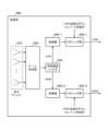
- FIG. 1 is a block diagram illustrating the functional configuration of a radar device according to the disclosed technology.
- FIG. 2 is a block diagram illustrating a functional configuration of a receiving system 600 employed in a radar device according to the disclosed technology.
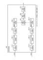
- FIG. 3 is a block diagram illustrating a functional configuration of a signal processing system 700 employed in a radar device according to the disclosed technique.
- FIG. 4 is an explanatory diagram showing an aspect of the integral processing section 760 in the radar device according to the first embodiment.
- FIG. 5 is an explanatory diagram illustrating the azimuth angle and the elevation angle.
- FIG. 6 is an explanatory diagram illustrating the processing content of the distance speed map generation unit 740-1 in the radar device according to the first embodiment.
- FIG. 7 is an explanatory diagram showing the processing content of the distance/velocity map generation unit 740-2 in the radar device according to the first embodiment.
- FIG. 8 is an explanatory diagram showing speed axis correction, which is the processing content of the interpolation processing unit 750 in the radar device according to the first embodiment.
- FIG. 9 is an explanatory diagram showing distance axis correction, which is the processing content of the interpolation processing unit 750 in the radar device according to the first embodiment.
- FIG. 10 is an example of a distance speed map obtained by the radar device according to the disclosed technique.
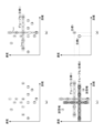
- FIG. 11 is a flowchart showing the grouping processing procedure performed by the target detection processing section 3000 in the radar device according to the first embodiment.
- FIG. 12 is an explanatory diagram showing a grouping processing procedure performed by the target detection processing section 3000 in the radar device according to the first embodiment.
- FIG. 13 is an explanatory diagram showing aspects of partial functional blocks in the radar device according to the second embodiment.
- FIG. 14 is an explanatory diagram showing aspects of partial functional blocks in the radar device according to the third embodiment.
- FIG. 15 is a block diagram showing a detailed functional configuration of the pulse compression section 730 (730-F) in the radar device according to the third embodiment.
- FIG. 16 is a first explanatory diagram showing aspects of partial functional blocks in the radar device according to the fourth embodiment.
- FIG. 17 is a second explanatory diagram showing aspects of partial functional blocks in the radar device according to the fourth embodiment.
- FIG. 18 is an explanatory diagram showing aspects of partial functional blocks in the radar device according to the fifth embodiment.
- FIG. 19 is a block diagram showing a detailed functional configuration of the integral processing section 760 in the radar device according to the fifth embodiment.
- FIG. 20 is a time-series explanatory diagram showing how the radar device according to the fifth embodiment transmits and receives data over a plurality of CPIs.
- FIG. 21 is an explanatory diagram showing aspects of partial functional blocks in the radar device according to the sixth embodiment.
- FIG. 22 is a distance speed map illustrating how the radar device according to the sixth embodiment sets the ambiguity range.
- FIG. 1 is a block diagram illustrating the functional configuration of a radar device according to the disclosed technology.
- the radar device according to the present disclosure includes an LPRF radar device 1000, an HPRF radar device 2000, and a target detection processing section 3000.
- LPRF means Low Pulse Repetition Frequency.
- LPRF has little distance ambiguity and is therefore suitable for observing the distance to a target (Tgt).
- HPRF means High Pulse Repetition Frequency.
- HPRF has little velocity ambiguity and is therefore suitable for observing the velocity of the target (Tgt).
- the LPRF radar device 1000 includes three systems: an LPRF radar transmission system 100, a reception system 600, and a signal processing system 700. In FIG.
- each of the receiving system 600 and signal processing system 700 in the LPRF radar device 1000 has a "1-" added before the code. Also in this specification, when emphasizing that the component is a component in the LPRF radar device 1000, "1-" is added before the respective code, such as “1-600" and “1-700”. .
- the HPRF radar device 2000 includes three systems: an HPRF radar transmission system 200, a reception system 600, and a signal processing system 700. In FIG. 1, each of the receiving system 600 and signal processing system 700 in the HPRF radar device 2000 has a "2-" added in front of the code. Also in this specification, when it is emphasized that the component is a component in the HPRF radar device 2000, "2-" is added before the respective code, such as “2-600” and “2-700”. .
- the thick wavy line arrow in FIG. 1 indicates that the LPRF pulse generated by the LPRF transmitter 110 is being transmitted toward the target (Tgt) by the LPRF transmitting antenna 120.
- the thin wavy line arrow in FIG. 1 indicates the LPRF pulse reflected by the target (Tgt) (hereinafter referred to as "LPRF reflected wave").
- the LPRF reflected waves are received by the receiving systems 600 (1-600, 2-600) of the LPRF radar device 1000 and the HPRF radar device 2000, respectively.
- the thick dotted line arrow in FIG. 1 indicates that the HPRF pulse generated by the HPRF transmitter 210 is being transmitted toward the target (Tgt) by the HPRF transmitting antenna 220.
- the thin dotted wavy line arrow in FIG. 1 indicates the HPRF pulse reflected by the target (Tgt) (hereinafter referred to as "HPRF reflected wave").
- the HPRF reflected waves are received by the receiving systems 600 (1-600, 2-600) of the LPRF radar device 1000 and the HPRF radar device 2000, respectively.
- the LPRF radar transmission system 100 includes an LPRF transmitter 110 and an LPRF transmission antenna 120.
- HPRF radar transmission system 200 includes an HPRF transmitter 210 and an HPRF transmission antenna 220.
- FIG. 2 is a block diagram illustrating a functional configuration of a receiving system 600 employed in a radar device according to the disclosed technique.
- the receiving system 600 employed in the radar device according to the disclosed technology is included in each of the LPRF radar device 1000 and the HPRF radar device 2000, but the receiving system 600 (1-600, 2-600) may have the same structure.
- the receiving system 600 includes an element antenna 610, a beam forming section 620, a band pass filter 630, a receiver 640 (640-1, 640-2), and a mixing section 650 (650-1). , 650-2).
- the reception system 600 is divided into an LPRF system and an HPRF system from the stage after the bandpass filter 630 to the output.
- the components in the LPRF system are a receiver 640-1 and a mixing section 650-1.
- the components in the HPRF system are a receiving system 600-2 and a mixing section 650-2.
- FIG. 3 is a block diagram illustrating a functional configuration of a signal processing system 700 employed in a radar device according to the disclosed technique.
- the signal processing system 700 includes an AD converter 710 (710-1, 710-2), a pulse hit direction processing section 720 (720-1, 720-2), and a pulse compression section 730 ( 730-1, 730-2), a distance speed map generation section 740 (740-1, 740-2), an interpolation processing section 750, an integration processing section 760, and a comparison processing section 770.
- AD converter 710 710-1, 710-2
- 720-1, 720-2 pulse hit direction processing section
- a pulse compression section 730 730-1, 730-2
- a distance speed map generation section 740 (740-1, 740-2 an interpolation processing section 750
- an integration processing section 760 an integration processing section 760
- a comparison processing section 770 As shown in FIG.
- the signal processing system 700 employed in the radar device according to the disclosed technology is included in each of the LPRF radar device 1000 and the HPRF radar device 2000, and the signal processing system 700 (1- 700, 2-700) may have the same structure.
- the signal processing system 700 is divided into an LPRF system and an HPRF system from the input to the stage before the interpolation processing section 750.
- the components in the LPRF system are an AD converter 710-1, a pulse hit direction processing section 720-1, a pulse compression section 730-1, and a distance velocity map generation section 740-1.
- the components in the HPRF system are an AD converter 710-2, a pulse hit direction processing section 720-2, a pulse compression section 730-2, and a distance velocity map generation section 740-2.
- FIG. 4 is an explanatory diagram showing an aspect of the integral processing section 760 in the radar device according to the first embodiment.
- the integration processing unit 760 may perform PDI (Post Detection Integration). More specifically, in the radar device according to the first embodiment, the integral processing section 760 performs incoherent integration, that is, frequency domain integration, on the range velocity map sent from the interpolation processing section 750.
- PDI Post Detection Integration
- the beam forming unit 620 configuring the receiving system 600 is a component that separates the signal received by the element antenna 610 into each of a plurality of regions defined by an azimuth angle and an elevation angle.
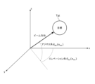
- FIG. 5 is an explanatory diagram illustrating the azimuth angle and the elevation angle.
- FIG. 5 shows space in a left-handed XYZ coordinate system, and shows that the beam direction can be expressed by an azimuth angle and an elevation angle.
- the azimuth angle of the beam is represented by the letters ⁇ az (n az ).
- the argument n az is a number assigned to the azimuth angle, and takes a natural number from 1 to N az .
- the beam elevation angle is represented by the letters ⁇ el (n el ).
- the argument nel is a number assigned to the elevation angle, and takes a natural number from 1 to Nel . That is, it is assumed that in the radar device according to the disclosed technology, N el different elevation angles are defined in advance.
- the beam forming unit 620 outputs a signal (s j, solo, nel (t)) at time t.
- the signal (s j, claw, nel (t)) output from the beam forming section 620 is sent to a band pass filter 630.
- the bandpass filter 630 configuring the receiving system 600 is a component that separates the signal (s j, solo, nel (t)) sent from the beam forming section 620 into an LPRF system and an HPRF system.
- the bandpass filter 630 is composed of bandpass filters (for B 1 and B 2 ) for the LPRF pulse band (B 1 ) and the HPRF pulse band (B 2 ), respectively. Ru.
- bandpass filter 630 the signal component that has passed the band (B 1 ) of the LPRF pulse is sent to receiver 640-1. It can be considered that the same processing as in the radar device according to the prior art is performed at the stage subsequent to the receiver 640-1.
- the signal component that has passed through the LPRF pulse band (B 1 ) finally becomes a range Doppler signal (s rd1 ) in the pulse compression section 730-1 shown in FIG. 3, and is sent to the range speed map generation section 740-1. It will be done.
- the subscript rd is derived from the initial letter of range doppler, which is the English word for range doppler, and the subscript 1 indicates that it is an LPRF system. show.
- a range Doppler signal (s rd1 ) is created for each of n az and n el .
- bandpass filter 630 the signal component that has passed the band (B 2 ) of the HPRF pulse is sent to receiver 640-2. It can be considered that the same processing as in the radar device according to the prior art is performed at the stage subsequent to the receiver 640-2.
- the signal component that has passed through the HPRF pulse band (B 2 ) finally becomes a range Doppler signal (s rd2 ) in the pulse compression section 730-2 shown in FIG. 3, and is sent to the range speed map generation section 740-2. It will be done.
- a range Doppler signal (s rd2 ) is created for each of n az , n el .
- the LPRF range/velocity map generation unit 740-1 constituting the signal processing system 700 is a component that generates a range/velocity map.
- the range-velocity map generation unit 740-1 of the LPRF system considers Doppler velocity ambiguity (hereinafter referred to as "velocity ambiguity ( vamb )") when generating a range-velocity map. If the velocity of the target (Tgt) related to the target signal of the n d -th Doppler bin is v 1 (n d ), then the ghost containing velocity ambiguity (va amb ) can be expressed in principle by the following equation.
- Equation (1) It can be any v 1 .
- n is an integer.
- c represents the speed of light
- f1 represents the transmission frequency of the LPRF radar device 1000
- TLPRI represents the pulse repetition period of the LPRF pulse.
- the horizontal bar of the accent symbol used in equation (1) indicates a value related to a real image that does not include ambiguity. From another perspective, equation (1) expresses that the interval at which the velocity ambiguity ( vamb ) occurs is regular. Note that the details of the ghost shown in equation (1) will become clear from the explanation of FIGS. 10 and 12, which will be described later.
- the distance and speed map generation unit 740-1 of the LPRF system performs a process of concatenating distance and speed maps in consideration of speed ambiguity ( vamb ).
- FIG. 6 is an explanatory diagram illustrating the processing content of the distance speed map generation unit 740-1 in the radar device according to the first embodiment.
- the upper part of FIG. 6 shows that Doppler bins (n d , from 1 to N d1 ) are set in consideration of the magnitude of velocity ambiguity ( vamb ).
- the middle part of FIG. 6 shows how the distance and speed map generation unit 740-1 of the LPRF system connects the distance and speed maps.
- the lower part of FIG. 6 shows how the Doppler bin number (indicated as "velocity bin number" in FIG. 6) is redefined for the new distance speed map (M rd1 ) obtained by concatenation. There is.
- the Doppler bin numbers (n d ) are arranged in ascending order of speed, and are set to 1, 2, . . . , N d1 .
- the new range and speed map (M rd1 ) created by the range and speed map generation unit 740-1 of the LPRF system is sent to the interpolation processing unit 750.
- the range speed map generation unit 740-2 of the HPRF system that constitutes the signal processing system 700 is a component that generates a range speed map.
- the range speed map generation unit 740-2 of the HPRF system takes into consideration the ambiguity of distance (also referred to as range) (hereinafter referred to as "range ambiguity (r amb )”) when generating the distance speed map. do. If the distance of the target (Tgt) related to the target signal of the nr- th range bin is r 2 (n r ), the ghost including the distance ambiguity (r amb ) can in principle be expressed by the following equation. It can be any r 2 .
- Equation (2) indicates that the intervals at which the distance ambiguity (r amb ) occurs are regular. Note that the details of the ghost shown in equation (2) will become clear from the explanation of FIGS. 10 and 12, which will be described later.
- the range-velocity map generation unit 740-2 of the HPRF system performs a process of concatenating range-velocity maps in consideration of range ambiguity (r amb ).
- FIG. 7 is an explanatory diagram showing the processing content of the distance/velocity map generation unit 740-2 in the radar device according to the first embodiment.
- the left column of FIG. 7 shows that range bins (n r , from 1 to N r2 ) are set in consideration of the magnitude of the distance ambiguity (r amb ).
- the middle row in FIG. 7 shows how the range and speed map generation unit 740-2 of the HPRF system connects the range and speed maps. In the middle row of FIG.
- the double-headed line segment labeled "assumed target distance range” literally represents the range of distance (range) that the target (Tgt) that is assumed in advance can take.
- the minimum value (N min ) and maximum value (N max ) of n in equation (2) are determined from the range of distances (ranges) that the target (Tgt) can assume in advance.
- the right column in FIG. 7 shows how the range bin number (indicated as "range bin number” in FIG. 7) is redefined for the new range speed map (M rd2 ) obtained by concatenation. There is.
- the range bin numbers (n r ) are arranged in descending order of distance as 1, 2, ..., Nr2.
- the new range speed map (M rd2 ) created by the range speed map generation unit 740-2 of the HPRF system is created by interpolation. It is sent to the processing section 750.
- the interpolation processing unit 750 configuring the signal processing system 700 takes into consideration the information obtained by the LPRF system and the information obtained by the HPRF system, and performs a process of interpolating and correcting range bins and Doppler bins in the range speed map. It is a component that performs.
- FIG. 8 is an explanatory diagram showing speed axis correction, which is the processing content of the interpolation processing unit 750 in the radar device according to the first embodiment.
- FIG. 9 is an explanatory diagram showing distance axis correction, which is the processing content of the interpolation processing unit 750 in the radar device according to the first embodiment.
- the upper part of FIG. 8 shows a new distance speed map (M rd1 ) created by the distance speed map generation unit 740-1 of the LPRF system and a new distance speed map (M rd1 ) created by the distance speed map generation unit 740-2 of the HPRF system.
- M rd1 the distance speed map generated by the distance speed map generation unit 740-1 of the LPRF system
- M rd1 the distance speed map generation unit 740-2 of the HPRF system.
- the horizontal axis is the Doppravin of the range speed map (M rd1 ) created by the LPRF system
- the vertical axis is the Doppravin of the range speed map (M rd2 ) created by the HPRF system, and the correlation between these is plotted.
- the straight line described as "linear approximation straight line" in the lower part of FIG. 8 is the Doppravin of the range velocity map (M rd1 ) created by the LPRF system, the Doppravin of the range velocity map (M rd2 ) created by the HPRF system, This shows that there is a correlation that can be approximated linearly.
- the interpolation processing unit 750 constituting the signal processing system 700 can appropriately interpolate and correct the Doppler bin in the distance speed map, assuming that the correlation represented by the linear approximation straight line is positive.
- the upper part of FIG. 9 shows a new distance speed map (M rd1 ) created by the distance speed map generation unit 740-1 of the LPRF system and a new distance speed map (M rd1 ) created by the distance speed map generation unit 740-2 of the HPRF system.
- M rd1 the distance speed map created by the distance speed map generation unit 740-1 of the LPRF system
- M rd1 the distance speed map generated by the distance speed map generation unit 740-2 of the HPRF system.
- the straight line described as "linear approximation straight line” in the lower part of FIG. 9 is the range bin of the distance speed map (M rd1 ) created by the LPRF system, and the range bin of the distance speed map (M rd2 ) created by the HPRF system, This shows that there is a correlation that can be approximated linearly.
- the interpolation processing unit 750 constituting the signal processing system 700 can appropriately interpolate and correct the range bins in the distance speed map, assuming that the correlation represented by the linear approximation straight line is positive.
- the distance speed map interpolated and corrected by the interpolation processing section 750 is sent to the integration processing section 760.
- the integral processing unit 760 that constitutes the signal processing system 700 is a component that performs integral processing to improve the S/N ratio.
- the integration processing unit 760 according to the first embodiment performs PDI on the distance speed map. This specification refers to the range speed map with PDI implemented as a PDI signal (p rd ) to distinguish it from the range speed map before PDI was implemented.
- the PDI signal (p rd ) can also be thought of as a function using n r , nd , n az , and nel as arguments.
- the PDI signal (p rd ) is given, for example, by the following equation.
- the PDI signal ( prd ) is calculated based on the relationship that the square of the signal amplitude represents the power.
- the PDI signal (p rd ) generated by the integral processing section 760 is sent to the comparison processing section 770.
- a comparison processing unit 770 configuring the signal processing system 700 converts the component of the signal (PDI signal (p rd ) in the first embodiment) that has been integrally processed by the integration processing unit 760 to a preset threshold (also called a threshold). This is a component that determines whether the signal is a target signal or an unnecessary signal for the target (Tgt).
- the comparison processing unit 770 numbers the components of the PDI signal (p rd ) that exceed the threshold in the order in which they are detected. In the comparison processing section 770, the components of the PDI signal (p rd ) exceeding the threshold are sent to the target detection processing section 3000 as target signal candidates.
- the PDI signal (p rd ) can be considered as a function using n r , nd , n az , and n el as arguments.
- the comparison processing unit 770 records n r , n d , n az , and n el when the PDI signal (p rd ) exceeds the threshold value, for example, as a structure.
- the signal processing system 700 (1-700) in the LPRF radar device 1000 may define the structure (X 1 ) as follows, for example.
- k 1 is a variable used in the signal processing system 700 (1-700)
- K 1 is the total number of components of the PDI signal (p rd ) exceeding the threshold in the signal processing system 700 (1-700).
- Elements (also referred to as fields) of the structure (X 1 ) may include, in addition to those shown in equation (4), a p rd value that exceeds the k 1st threshold.
- Information on the structure (X 1 ) obtained by the signal processing system 700 (1-700) is sent to the target detection processing section 3000 together with information on the PDI signal (p rd ).
- the signal processing system 700 (2-700) in the HPRF radar device 2000 may define, for example, the following structure (X 2 ).
- k 2 is a variable used in the signal processing system 700 (2-700)
- K 2 is the total number of components of the PDI signal (p rd ) exceeding the threshold in the signal processing system 700 (2-700).
- Elements (also referred to as fields) of the structure (X 2 ) may include, in addition to those shown in equation (5), a p rd value that exceeds the k second threshold.
- Information on the structure (X 2 ) obtained by the signal processing system 700 (2-700) is sent to the target detection processing section 3000 together with information on the PDI signal (p rd ).
- the target detection processing unit 3000 is based on the information sent from the signal processing system 700 (1-700) of the LPRF radar device 1000 and the information sent from the signal processing system 700 (2-700) of the HPRF radar device 2000. , a component for detecting a target (Tgt). It can be said that the processing performed by the target detection processing section 3000 can be roughly divided into two types. The first step is to confirm the correspondence. The second process is called "1 out of 2 detection".
- the confirmation of the correspondence relationship performed by the target detection processing unit 3000 refers to the information on the structure (X 1 ) sent from the signal processing system 700 (1-700) in the LPRF radar device 1000 and the signal processing system in the HPRF radar device 2000.
- the confirmation of the correspondence relationship performed by the target detection processing unit 3000 may be performed in combination with the tracking function of the radar device.
- the target detection processing unit 3000 performs the correspondence confirmation and the "1 out of 2 detection” processing, and generates the structure (X ADD ).
- the structure (X ADD ) generated by the target detection processing unit 3000 is a target (Tgt) detected by only one of the two radar devices, the LPRF radar device 1000 and the HPRF radar device 2000. Contains information about.
- FIG. 10 is an example of a distance speed map obtained by the radar device according to the disclosed technique.
- X ADD the structure generated by the target detection processing unit 3000
- records having the same set of n az and n el are extracted and the points (n r , n d ) are plotted as shown in FIG.
- the distance speed map illustrated in is obtained.
- the distance and speed map illustrated in FIG. 10 is a distance and speed map when a certain target (Tgt) is assumed.
- the radar device according to the disclosed technology uses information on velocity ambiguity (v amb ) shown in equation (1) and information on distance ambiguity (r amb ) shown in equation (2). Using this method, a plurality of plots appearing in the range velocity map can be grouped as originating from a certain target (Tgt). This grouping process is performed by the target detection processing section 3000.
- FIG. 11 is a flowchart showing the grouping processing procedure performed by the target detection processing section 3000 in the radar device according to the first embodiment.
- FIG. 12 is an explanatory diagram showing a grouping processing procedure performed by the target detection processing section 3000 in the radar device according to the first embodiment.
- a step indicated as S1 in FIG. 11 is a processing step for initializing a variable (k) used in the grouping process.
- the initial value 1 is assigned to the variable (k).
- the distance speed map is in the state shown in FIG. 12(a). In the case shown in FIG. 12(a), there are 16 plots in the distance speed map that exceed the threshold.
- the step shown as S2 in FIG. 11 is a processing step of performing grouping in the distance direction based on distance ambiguity (r amb ) information.
- the target detection processing unit 3000 checks whether there is another plot at a position that is an integer multiple of the distance ambiguity (r amb ) in the distance direction with the kth plot as the center.
- the processing content of S2 can be explained using the distance speed map shown in FIG. 12(b).
- the step shown as S3 in FIG. 11 is a processing step of performing grouping in the direction of velocity based on information on velocity ambiguity ( vamb ).
- the target detection processing unit 3000 checks whether there is another plot at a position that is an integer multiple of the velocity ambiguity ( vamb ) in the velocity direction with the kth plot as the center.
- the processing content of S3 can be explained using the distance speed map shown in FIG. 12(b).
- the step shown as S4 in FIG. 11 is a processing step for checking whether S2 and S3 have been performed for all k, that is, all plots. If S2 and S3 have not yet been performed for all plots, ie NO in S4, the process proceeds to S6. In S6, the variable (k) used here is incremented (an operation of adding 1 to the numerical value). Thereafter, the processing step proceeds to S2 for the second round and thereafter.
- the processing contents of S2 and S3 after the second round can be explained using the distance speed map shown in FIG. 12(c).
- the step indicated as S5 in FIG. 11 relates to actions on ungrouped plots.
- the target detection processing unit 3000 determines that a plot that does not belong to any group is noise and a false alarm.
- the processing content of S5 can be explained using the distance speed map shown in FIG. 12(c).
- the step shown as S7 in FIG. 11 is a processing step for eliminating so-called virtual image plots (also called ghosts) containing ambiguity and finding so-called real image plots containing no ambiguity for each group. .
- the signal strength associated with a real image plot is stronger than the signal strength associated with a virtual image plot. Therefore, it is conceivable to find real image plots from each group based on signal strength information.
- the processing content of S7 can be explained using the distance speed maps shown in FIGS. 12(c) and 12(d).
- the plot located at the intersection of the crosses can be inferred to be the real image plot.
- the range ambiguity (r amb ) and the velocity ambiguity (va amb ) occur simultaneously.
- range ambiguity (r amb ) and velocity ambiguity (va amb ) occur simultaneously, a virtual image plot appears in the form of a grid in the range velocity map.
- the radar device since the radar device according to Embodiment 1 has the above configuration, it can detect a target (Tgt) using radio waves having a plurality of different PRFs, and has a wide variety of targets (Tgt) compared to conventional radar devices. Target (Tgt) detection that is resistant to noise based on such information can be realized.
- Embodiment 2 The radar device according to Embodiment 2 is a modification of the radar device according to the presently disclosed technology. Unless otherwise specified, the same symbols used in the first embodiment are used in the second embodiment. Furthermore, in the second embodiment, descriptions that overlap with those in the first embodiment are omitted as appropriate.
- FIG. 13 is an explanatory diagram showing aspects of partial functional blocks in the radar device according to the second embodiment.
- FIG. 13 is an explanatory diagram showing, in more detail, aspects of the pulse hit direction processing section 720 and the pulse compression section 730 in the radar device according to the second embodiment.
- a pulse hit direction processing section 720 performs pulse hit direction coherent integration
- a pulse compression section 730 performs phase correction type pulse compression.
- the radar device is based on the premise that the speed of the target (Tgt) can be estimated in advance.
- the speed of the target (Tgt) assumed in advance is given by the equation using the following symbols as a set of speeds (v c ).
- N d appearing in the subscript on the right side of equation (6) is the maximum value that the Dopp Rabin number ( nd ) appearing in equation (1) can take, and is the total number of Dopp Rabins.
- the radar device assumes the speed of the target (Tgt) in advance for the total number of Doppler bins.
- the pulse hit direction processing unit 720 according to the second embodiment corrects the phase rotation of the signal due to the Doppler frequency using the velocity set (v c ) of the target (Tgt) assumed in advance, and then determines the pulse hit direction. Perform coherent integration to .
- the pulse hit direction processing section 720 has two types: one for the LPRF system (720-1) and one for the HPRF system (720-2), but in both systems, the pulse hit direction processing section 720 has the same processing content.
- the processing performed by the pulse hit direction processing unit 720 according to the second embodiment is given by, for example, the following equation.
- S j on the right side of equation (7) is the signal sent from the AD converter 710
- S f on the left side of equation (7) is the signal after processing in the pulse hit direction processing section 720 (hereinafter referred to as "coherent integral integration").
- signal (S f ) is a variable (pulse hit number) that takes a natural number from 1 to N h
- N h is the total number of discrete time signal sequences sent from the AD converter 710.
- the subscript nh appended to t represents the time at the nh - th sampling.
- f s appearing on the right side of equation (7) is the transmission frequency.
- f s is f 1 appearing in equation (1). Note that the pulse hit direction processing unit 720 performs the process shown by equation (7) for all combinations of n az and n el . If there is a missing portion in the data, the pulse hit direction processing unit 720 according to the second embodiment may fill in the missing portion with a predetermined value such as an average value, median value, or 0 as appropriate.
- the coherent integrated signal (S f ) generated by the pulse hit direction processing section 720 according to the second embodiment is sent to the pulse compression section 730.
- the pulse compression unit 730 according to the second embodiment corrects the frequency shift of the target signal power spectrum due to Doppler and performs pulse compression.
- the frequency shift correction performed in pulse compression section 730 according to the second embodiment is given by, for example, the following equation.
- the signal (s′ f ) whose phase has been corrected in the pulse compression unit 730 according to the second embodiment is sent to the distance speed map generation unit 740.
- the subsequent processing contents are similar to those described in the first embodiment.
- the radar device according to the second embodiment since the radar device according to the second embodiment has the above configuration, phase rotation due to Doppler can be corrected. Due to this effect, the radar device according to the second embodiment has an effect that, in addition to the effect shown in the first embodiment, the integral loss in pulse compression is small.
- Embodiment 3 The radar device according to Embodiment 3 is a modification of the radar device according to the disclosed technique. Unless otherwise specified, in the third embodiment, the same symbols as those used in the previous embodiments are used. Furthermore, in the third embodiment, descriptions that overlap with those of the previously described embodiments will be omitted as appropriate.
- FIG. 14 is an explanatory diagram showing aspects of partial functional blocks in the radar device according to the third embodiment. As shown in FIG. 14, in the radar device according to the disclosed technique, the functions of the pulse hit direction processing section 720 and the pulse compression section 730 may be replaced with a pulse compression section 730-F that performs high-speed pulse compression. .
- FIG. 15 is a block diagram showing the detailed functional configuration of the pulse compression section 730-F in the radar device according to the third embodiment.
- the pulse compression section 730-F according to the third embodiment includes a received pulse FFT section 730-F-1, a pulse direction CZT section 730-F-2, and a reference pulse generation section 730-F. -3, a reference pulse FFT section 730-F-4, a multiplication section 730-F-5, and an IFFT processing section 730-F-6.
- the received pulse FFT section 730-F-1 which constitutes the pulse compression section 730-F, is a component for performing FFT in the distance direction (hereinafter referred to as "range FFT").
- range FFT performed by the received pulse FFT section 730-F-1 is given by the following equation.
- the conversion in which the subscript ⁇ Range'' is written to F expressed in script typeface represents a range FFT.
- s j in Equation (9) is the same as that appearing in Equation (7), and represents the signal sent from AD converter 710.
- n h in equation (9) is the same as that appearing in equation (7), and is a variable (pulse hit number) that takes a natural number from 1 to N h .
- the received pulse FFT unit 730-F-1 performs the range FFT shown by equation (9) for all combinations of n az and n el .
- the signal (s fj ) obtained by the range FFT in the received pulse FFT section 730-F-1 is sent to the pulse direction CZT section 730-F-2.
- the pulse direction CZT section 730-F-2 that constitutes the pulse compression section 730-F is a component that performs chirp z-transform in the pulse hit direction.
- the letters CZT included in the name of the pulse direction CZT section 730-F-2 are derived from the initials of Chirp Z-Transform, which means chirp Z-transform. Chirp z-transform allows convolution operations to be performed quickly. The details of the chirp z-transform performed by the pulse direction CZT section 730-F-2 become clear by introducing the following variables (f and g).
- equation (10) and W appearing in equation (10) and equation (11) are given as follows.
- a given by equation (12) and W given by equation (13) are variables used in chirp z-transform.
- ⁇ v c appearing in equation (13) is the difference between adjacent velocities in the set of velocities (v c ) in equation (6), which is defined as the velocity of the target (Tgt) assumed in advance.
- the velocity (v c,1 , v c,2 , ..., v c, Nd ) of the target (Tgt) assumed in advance is expressed as an arithmetic progression with ⁇ v c as the difference.
- ⁇ v c the difference.
- f a appearing in equations (12) and (13) is a frequency obtained by adding a distance-dependent frequency (such as a beat frequency when chirp modulation is used) to the transmission frequency.
- T s appearing in equation (12) represents the sampling period
- T h appearing in equation (13) represents the pulse hit interval.
- the pulse direction CZT section 730-F-2 performs FFT processing on f given by equation (10) and g given by equation (11), respectively.
- F and G of the function obtained by FFT processing can be expressed as follows.
- F expressed in script type represents Fourier transform, that is, FFT. Note that in the radar device according to the second embodiment described above, the relationship between the pulse hit number (n h ) and the Dopp Rabin number (n d ) is shown in equation (7) regarding the processing content of the pulse hit direction processing unit 720. has been done.
- the radar device uses the pulse hit number (n h ) and the Dopp Rabin number (n d ) in equations (14) and (15) related to Fourier transform. The relationship is shown. Due to the nature of FFT, N d is equal to N h .
- the pulse direction CZT section 730-F-2 calculates a value (s' f2 ) given by the following equation.
- This formula (16) according to the third embodiment corresponds to the formula (8) (the formula for deriving s′ f ) according to the second embodiment described above.
- s' f2 calculated by the pulse direction CZT section 730-F-2 is sent to the multiplication section 730-F-5.
- the reference pulse generation unit 730-F-3 that constitutes the pulse compression unit 730-F is a component that generates a reference pulse (s s ) used in pulse compression processing. It is assumed that the sampling number related to the reference pulse (s s ) is represented by ns . n s takes a natural number from 1 to N s . The reference pulse (s s ) is given by a function using the n s th sampling time (t ns ) as an argument.
- the reference pulse FFT unit 730-F-4 that constitutes the pulse compression unit 730-F is literally a component that performs FFT on the reference pulse (s s ).
- the reference pulse FFT section 730-F-4 may, for example, perform correction given by the following equation, that is, correction of phase rotation due to Doppler, before performing FFT.
- T s is the sampling period of the reference pulse (s s ).
- the signal sequence subjected to FFT processing by the reference pulse FFT unit 730-F-4 (hereinafter referred to as "FFT output signal sequence") can be expressed as follows.
- the curly braces used in equation (18) represent a signal sequence.
- Nr has a value equal to Ns .
- the FFT output signal sequence generated by the reference pulse FFT section 730-F-4 is sent to the multiplication section 730-F-5.
- the multiplication unit 730-F-5 that constitutes the pulse compression unit 730-F receives the signal (s′ f2 ) from the pulse direction CZT unit 730-F-2 and the signal from the reference pulse FFT unit 730-F-4. (s′ sf ). Specifically, the multiplication unit 730-F-5 performs the multiplication process shown below.
- the superscript asterisk appearing on the right side of equation (19) represents a complex conjugate.
- the IFFT processing unit 730-F-6 that constitutes the pulse compression unit 730-F is a component that performs inverse Fourier transform.
- IFFT in the name of the IFFT processing unit 730-F-6 is derived from the initials of Inverse Fast Fourier Transform.
- the processing subsequent to the pulse compression unit 730-F is the same as the processing in the radar device according to the previously described embodiments.
- the radar device according to Embodiment 3 since the radar device according to Embodiment 3 has the above configuration, it can perform CZT processing. Due to this effect, the radar device according to the third embodiment can perform convolution calculation at high speed and correct phase rotation due to Doppler, in addition to the effects shown in the first embodiment.
- Embodiment 4 The radar device according to Embodiment 4 is a modification of the radar device according to the disclosed technique. Unless otherwise specified, in the fourth embodiment, the same symbols as those used in the previously described embodiments are used. Furthermore, in the fourth embodiment, descriptions that overlap with those of the previously described embodiments will be omitted as appropriate.
- FIG. 16 is a first explanatory diagram showing aspects of partial functional blocks in the radar device according to the fourth embodiment.
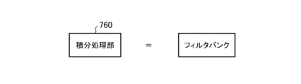
- the signal processing system 700 may perform signal processing using a combination of filter banks.
- a filter bank is an array of bandpass filters, a circuit that divides an input signal into multiple components.
- the target detection processing unit 3000 according to the disclosed technology includes N f independent target detection processing units 3000 (3000-#1, 3000-#2, ..., 3000-#N f ). It may be composed of.
- N f is the total number of bandpass filters in the filter bank.
- n f (n f is a natural number taking 1, 2, ..., N f ) is the identification number of the bandpass filter in the filter bank, then in both the signal processing system 700 of the LPRF system and the HPRF system, the n fth band The signal components that have passed through the pass filter are sent to the corresponding target detection processing section 3000-# nf .
- FIG. 17 is a second explanatory diagram showing aspects of partial functional blocks in the radar device according to the fourth embodiment.
- the filter bank included in the signal processing system 700 may be realized by, for example, the integral processing section 760 in the signal processing system 700.
- the integral processing unit 760 according to the fourth embodiment includes a distance speed map (M rd1 ) created by the LPRF system and a distance speed map (M rd2 ) created by the HPRF system. is sent.
- the distance speed map (M rd1 ) and the distance speed map (M rd2 ) are decomposed into each component by a filter bank held by the integral processing unit 760.
- the integral processing unit 760 according to the fourth embodiment performs coherent integration after matching the phases of the two distance velocity maps in each component. Generally, it is not easy to know the phase difference between two range-velocity maps.
- the integral processing unit 760 specifically performs processing given by the following equation.
- the radar device prepares in advance a filter bank consisting of N f bandpass filters, and creates a range speed map (M rd1 ) and a range speed map (M rd2 ). After phase correction is performed on either one of the range velocity maps using an integer multiple of 2 ⁇ /N f , coherent integration is performed.
- M rd on the left side of equation (20) is referred to as a coherent integrated signal (M rd ).
- the integral processing unit 760 may calculate p rd from the coherent integrated signal (M rd ) based on the relationship that the square of the signal amplitude represents the power.
- the calculation of p rd performed by the integral processing unit 760 is given by the following equation as an image. Equation (21) according to the fourth embodiment corresponds to equation (3) according to the first embodiment.
- ⁇ Target detection processing unit 3000 (3000-#1, 3000-#2, ..., 3000-#N f ) according to Embodiment 4>>>
- the target detection processing unit 3000 (3000-#1, 3000-#2, ..., 3000-#N f ) according to the fourth embodiment selects a coherently integrated signal with the smallest loss in the filter bank as a target (Tgt).
- the target (Tgt) is detected as a target signal related to the target signal.
- the radar device according to the fourth embodiment since the radar device according to the fourth embodiment has the above configuration, the range speed map (M rd1 ) created by the LPRF system and the range speed map (M rd2 ) created by the HPRF system are coherent. It can be integrated. Due to this effect, the radar device according to the fourth embodiment has the effect that the S/N ratio can be improved in addition to the effect shown in the first embodiment.
- Embodiment 5 is a modification of the radar device according to the disclosed technology. Unless otherwise specified, in the fifth embodiment, the same symbols as those used in the previously described embodiments are used. Furthermore, in the fifth embodiment, descriptions that overlap with those of the previously described embodiments will be omitted as appropriate.
- the radar device assumes that the LPRF transmitter 110 and the HPRF transmitter 210 transmit across multiple CPIs (Coherent Processing Intervals).
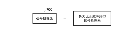
- FIG. 18 is an explanatory diagram showing aspects of partial functional blocks in the radar device according to the fifth embodiment. As shown in FIG. 18, the radar device according to the disclosed technology may perform signal processing using maximum ratio combining.
- FIG. 19 is a block diagram showing a detailed functional configuration of the integral processing section 760 in the radar device according to the fifth embodiment.
- signal processing using maximum ratio combining may be realized by the integral processing section 760 including a memory circuit and a maximum ratio combining section.
- the maximum ratio synthesis section may include a correlation matrix generation section, a weight calculation section, an addition processing section, and a CPI direction PDI.
- FIG. 20 is a time-series explanatory diagram showing how the radar device according to the fifth embodiment transmits and receives data over a plurality of CPIs.
- N cpi in "CPI number N cpi" described in FIG. 20 is the total number of CPIs.
- the memory circuit included in the integral processing section 760 according to the fifth embodiment is a component that stores signals as signals transmitted in units of CPI.
- the correlation matrix generation unit included in the integral processing unit 760 according to the fifth embodiment is a component that generates a correlation matrix of the transmitted signal.
- the weight calculation unit included in the integral processing unit 760 according to the fifth embodiment is a component that outputs the eigenvector corresponding to the maximum eigenvalue of the correlation matrix as a weight.
- the addition processing section included in the integral processing section 760 according to the fifth embodiment is a component that performs addition processing using weights.
- the CPI direction PDI included in the integral processing unit 760 according to the fifth embodiment is a component that performs incoherent integration in the CPI direction.
- the radar device assumes that the LPRF transmitter 110 and the HPRF transmitter 210 transmit across multiple CPIs (hereinafter, this assumption will be referred to as (referred to as "premises specific to Embodiment 5"). That is, in the interpolation processing unit 750 of the signal processing system 700 according to the fifth embodiment, the CPI unit is A distance and speed map will be sent to you. As described above, the distance speed map uses n r , nd , n az , and n el as arguments, as exemplified by Equation (3), for example.
- the distance speed map has a premise specific to the fifth embodiment, so in addition to these four arguments, a number identifying the CPI number (hereinafter, "CPI It is necessary to add the number (n cpi ) or simply “n cpi ” as an additional argument. Therefore, in consideration of ease of viewing, this specification omits n r , n d , n az , and n el in the argument when expressing the distance speed map according to the fifth embodiment, and only n cpi is described. do.
- the correlation matrix generation section included in the integral processing section 760 generates a correlation matrix of the transmitted signal.
- the correlation matrix generation section included in the integral processing section 760 generates a correlation matrix (R) given by the following equation.
- the superscript H added to the A matrix shown in equation (22) represents Hermitian transposition.
- N cpi appearing in equation (22) is the total number of CPIs, similar to N cpi appearing in FIG. 20. That is, n cpi takes a natural number from 1 to N cpi .
- the row size of the A matrix shown in equation (22) is N cpi .
- the weight calculation unit included in the integral processing unit 760 calculates the eigenvector (w max ) corresponding to the maximum eigenvalue ( ⁇ max ) of the correlation matrix (R) in order to calculate the weighting coefficient. do.
- the maximum eigenvalue ( ⁇ max ) and eigenvector (w max ) of the correlation matrix (R) have the following relationship.
- the lower part of Equation (23) represents the eigenvector (w max ) as a component, and the components (w max,1 and w max,2 ) of the eigenvector (w max ) are used as weighting coefficients.
- Equation (24) is a weighted addition process using the eigenvector (w max ) corresponding to the maximum eigenvalue ( ⁇ max ) of the correlation matrix (R), and realizes maximum ratio combining. Equation (24) according to the fifth embodiment corresponds to equation (20) according to the fourth embodiment.
- the CPI direction PDI included in the integral processing section 760 according to the fifth embodiment performs incoherent integration of the processing result (M rd ) of the addition processing section in the CPI direction.
- the incoherent integration in the CPI direction performed by the CPI direction PDI is given by the following equation.
- Formula (25) according to the fifth embodiment corresponds to formula (3) according to the first embodiment and formula (21) according to the fourth embodiment.
- the radar device according to the fifth embodiment since the radar device according to the fifth embodiment has the above configuration, the distance speed map (M rd1 ) created by the LPRF system and the distance speed map (M rd2 ) created by the HPRF system are maximized. It is possible to perform ratio synthesis. Due to this effect, the radar device according to the fifth embodiment has the effect that the S/N ratio can be improved in addition to the effect shown in the first embodiment.
- Embodiment 6 The radar device according to Embodiment 6 is a modification of the radar device according to the disclosed technology. Unless otherwise specified, in the sixth embodiment, the same symbols as those used in the previously described embodiments are used. Furthermore, in the sixth embodiment, descriptions that overlap with those of the previously described embodiments will be omitted as appropriate.
- Embodiments 1 to 5 it is assumed that ambiguity (more precisely, a virtual image including ambiguity) appears at a theoretically determined position.
- the radar device according to the sixth embodiment assumes a case where the position of the actually measured plot in the distance/velocity map deviates somewhat from the theoretically determined position.
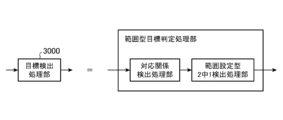
- FIG. 21 is an explanatory diagram showing aspects of partial functional blocks in a radar device according to Embodiment 6.
- the target detection processing unit 3000 performs range type target determination processing, which includes a correspondence detection processing unit and a range setting type 2/1 detection processing unit. It may be realized by the department.
- the range setting type 2/1 detection processing unit included in the target detection processing unit 3000 according to the sixth embodiment detects the ambiguities of the target signal related to the target (Tgt) even when signals near the position where ambiguity occurs. This is a component that sets the range of gravity and then performs 1 out of 2 detection processing. What is meant by "near the position where ambiguity occurs" will become clear from the explanation of FIG. 22 below.
- FIG. 22 is a distance speed map illustrating how the radar device according to the sixth embodiment sets the ambiguity range.
- the circle labeled "Target Signal" in the center shows a real image of the target signal related to the target (Tgt), which does not include ambiguity.
- other circles plotted at positions other than the center indicate virtual images of the target signal related to the target (Tgt), including ambiguity.
- a broken line circle outside the circle indicating the virtual image of the target signal related to the target (Tgt) indicates the area set by the target detection processing section 3000 according to the sixth embodiment. Note that FIG. 22 is an example of a distance speed map when there is one target (Tgt).
- the radar device determines that a plot appearing within the area set by the target detection processing unit 3000 is a virtual image regarding the target (Tgt) of interest.
- the radar device since the radar device according to the sixth embodiment has the above configuration, even if the virtual image regarding the target (Tgt) appears slightly shifted from the theoretically determined position, the information regarding the target (Tgt) can be used as information about the target (Tgt). can be processed.
- the radar device is not limited to the aspects illustrated in each embodiment, and may be implemented by combining each embodiment, modifying any component of each of the embodiments, or modifying any of the embodiments. Any component can be omitted in each of the above.
- the radar device has industrial applicability because it can be applied to the technical field of measuring the position and velocity of a target to be observed.
- 100 LPRF radar transmission system 110 LPRF transmitter, 120 LPRF transmission antenna, 200 HPRF radar transmission system, 210 HPRF transmitter, 220 HPRF transmission antennas, 600 receivers, 610 elements antenna, 620 beam format, 630 bands, 630 bands.
- Excess Filter 640 receiver, 650 mixing unit, 700 signal processing system, 710 AD converter, 720 pulse hit direction processing unit, 730 pulse compression unit, 730-F-1 received pulse FFT unit, 730-F-2 pulse direction CZT section, 730-F-3 reference pulse generation section, 730-F-4 reference pulse FFT section, 730-F-5 multiplication section, 730-F-6 IFFT processing section, 740 distance speed map generation section, 750 interpolation Processing unit, 760 Integral processing unit, 770 Comparison processing unit, 1000 LPRF radar device, 2000 HPRF radar device, 3000 Target detection processing unit.
Landscapes
- Engineering & Computer Science (AREA)
- Radar, Positioning & Navigation (AREA)
- Remote Sensing (AREA)
- Computer Networks & Wireless Communication (AREA)
- Physics & Mathematics (AREA)
- General Physics & Mathematics (AREA)
- Radar Systems Or Details Thereof (AREA)
Abstract
Description
図1は、本開示技術に係るレーダ装置の機能構成を例示するブロック図である。図1に示されるとおり本開示技術に係るレーダ装置は、LPRFレーダ装置1000と、HPRFレーダ装置2000と、目標検出処理部3000と、から構成される。LPRFは、Low Pulse Repetition Frequencyを意味する。LPRFは、距離アンビギュイティが少ないため、ターゲット(Tgt)の距離を観測することに適している。またHPRFは、High Pulse Repetition Frequencyを意味する。HPRFは、速度アンビギュイティが少ないため、ターゲット(Tgt)の速度を観測することに適している。
LPRFレーダ装置1000は、LPRFレーダ送信系100と、受信系600と、信号処理系700と、の3つの系統を備える。図1において、LPRFレーダ装置1000における受信系600及び信号処理系700は、それぞれ符号の前に「1-」が付加されている。本明細書においても、LPRFレーダ装置1000における構成部品であることを強調する場合は、「1-600」、「1-700」のように、それぞれ符号の前に「1-」が付加される。
HPRFレーダ装置2000は、HPRFレーダ送信系200と、受信系600と、信号処理系700と、の3つの系統を備える。図1において、HPRFレーダ装置2000における受信系600及び信号処理系700は、それぞれ符号の前に「2-」が付加されている。本明細書においても、HPRFレーダ装置2000における構成部品であることを強調する場合は、「2-600」、「2-700」のように、それぞれ符号の前に「2-」が付加される。
図1における細波線矢印は、ターゲット(Tgt)で反射されたLPRFパルス(以降、「LPRF反射波」と称する)を示している。LPRF反射波は、LPRFレーダ装置1000及びHPRFレーダ装置2000それぞれの受信系600(1-600、2-600)により受信される。
図1における細点波線矢印は、ターゲット(Tgt)で反射されたHPRFパルス(以降、「HPRF反射波」と称する)を示している。HPRF反射波は、LPRFレーダ装置1000及びHPRFレーダ装置2000それぞれの受信系600(1-600、2-600)により受信される。
図1に示されるとおり、HPRFレーダ送信系200は、HPRF用送信機210と、HPRF送信アンテナ220と、を含む。
図2に示されるとおり、受信系600は、素子アンテナ610と、ビーム形成部620と、帯域通過フィルタ630と、受信機640(640-1、640-2)と、ミキシング部650(650-1、650-2)と、を含む。図2に示されるように、受信系600は、帯域通過フィルタ630の後段から出力まで、LPRF系統とHPRF系統とに分かれている。LPRF系統における構成要素は、受信機640-1、及びミキシング部650-1、である。HPRF系統における構成要素は、受信系600-2、及びミキシング部650-2、である。
図3に示されるとおり、信号処理系700は、入力から補間処理部750の前段まで、LPRF系統とHPRF系統とに分かれている。LPRF系統における構成要素は、AD変換器710-1、パルスヒット方向処理部720-1、パルス圧縮部730-1、及び距離速度マップ生成部740-1、である。HPRF系統における構成要素は、AD変換器710-2、パルスヒット方向処理部720-2、パルス圧縮部730-2、及び距離速度マップ生成部740-2、である。
受信系600を構成するビーム形成部620は、素子アンテナ610により受信された信号を、アジマス角及びエレベーション角により定義された複数の領域のそれぞれに分離する構成要素である。
図5は、アジマス角とエレベーション角とを説明する説明図である。図5は、空間を左手系のXYZ座標系で示し、ビーム方向がアジマス角とエレベーション角とで表せることを示している。
図5において、ビームのアジマス角は、θaz(naz)の文字で表されている。ここで引数のnazは、アジマス角に付される番号であり、1からNazまでの自然数をとる。すなわち本開示技術に係るレーダ装置は、あらかじめNaz個の異なるアジマス角が定義されている、とする。
図5において、ビームのエレベーション角は、θel(nel)の文字で表されている。ここで引数のnelは、エレベーション角に付される番号であり、1からNelまでの自然数をとる。すなわち本開示技術に係るレーダ装置は、あらかじめNel個の異なるエレベーション角が定義されている、とする。
ビーム形成部620は、時刻tにおける信号(sj、naz、nel(t))を出力する。ビーム形成部620において出力された信号(sj、naz、nel(t))は、帯域通過フィルタ630へと送られる。
受信系600を構成する帯域通過フィルタ630は、ビーム形成部620から送られた信号(sj、naz、nel(t))を、LPRF系統とHPRF系統とに分離する構成要素である。帯域通過フィルタ630は、具体的には、LPRFパルスの帯域(B1)と、HPRFパルスの帯域(B2)との、それぞれ用のバンドパスフィルタ(B1用及びB2用)から構成される。
帯域通過フィルタ630において、LPRFパルスの帯域(B1)を通過した信号成分は、受信機640-1へと送られる。受信機640-1より後段においては、従来技術に係るレーダ装置と同じ処理が施されると考えてよい。LPRFパルスの帯域(B1)を通過した信号成分は、最終的に図3に示されるパルス圧縮部730-1においてレンジドップラ信号(srd1)となり、距離速度マップ生成部740-1へと送られる。なお、レンジドップラ信号を表す文字のsrd1において、下付添え字のrdは、レンジドップラの英語であるrange dopplerの頭文字を由来とし、下付添え字の1は、LPRF系統であることを示す。レンジドップラ信号(srd1)は、naz、nel、のそれぞれについて作成される。
帯域通過フィルタ630において、HPRFパルスの帯域(B2)を通過した信号成分は、受信機640-2へと送られる。受信機640-2より後段においては、従来技術に係るレーダ装置と同じ処理が施されると考えてよい。HPRFパルスの帯域(B2)を通過した信号成分は、最終的に図3に示されるパルス圧縮部730-2においてレンジドップラ信号(srd2)となり、距離速度マップ生成部740-2へと送られる。レンジドップラ信号(srd2)は、naz、nel、のそれぞれについて作成される。
信号処理系700を構成するLPRF系統の距離速度マップ生成部740-1は、距離速度マップを生成する構成要素である。LPRF系統の距離速度マップ生成部740-1は、距離速度マップを生成する際に、ドップラ速度のアンビギュイティ(以降、「速度アンビギュイティ(vamb)」と称する)を考慮する。
nd番目のドップラビンの目標信号に係るターゲット(Tgt)の速度をv1(nd)とすると、速度アンビギュイティ(vamb)を含むゴーストは、原理的には、以下の式で表されるいずれのv1にもなり得る。

ここで、nは整数である。式(1)におけるcは光速を、f1はLPRFレーダ装置1000の送信周波数を、TLPRIはLPRFパルスのパルス繰返し周期を、それぞれ表す。また、式(1)において用いられるアクセント記号の横棒は、アンビギュイティを含まない実像に係る値であることを示している。別の見方をすれば、式(1)は、速度アンビギュイティ(vamb)の発生間隔が規則的である、ということを表している。なお、式(1)に示されるゴーストの詳細は、後述の図10及び図12の説明により明らかとなる。
図6は、実施の形態1に係るレーダ装置における距離速度マップ生成部740-1の処理内容を示す説明図である。
図6上段は、速度アンビギュイティ(vamb)の大きさを考慮して、ドップラビン(nd、1からNd1まで)が設定されていることを表している。
図6中段は、LPRF系統の距離速度マップ生成部740-1が、距離速度マップを連接する様子を示している。図6中段において「想定する目標速度範囲」と記載された両矢印の線分は、文字どおり、あらかじめ想定されるターゲット(Tgt)が取り得る速度の範囲を表している。あらかじめ想定されるターゲット(Tgt)が取り得る速度の範囲から、式(1)におけるnについての最小値(Nmin)と最大値(Nmax)とが決定される。
図6下段は、連接することによって得られた新たな距離速度マップ(Mrd1)について、ドップラビン番号(図6においては「速度ビンの番号」と記載)をあらためて定義しなおしている様子を示している。ドップラビン番号(nd)は、速度を小さい順に並べて、1、2、…、Nd1としている。
LPRF系統の距離速度マップ生成部740-1で作成された新たな距離速度マップ(Mrd1)は、補間処理部750へと送られる。
信号処理系700を構成するHPRF系統の距離速度マップ生成部740-2は、距離速度マップを生成する構成要素である。HPRF系統の距離速度マップ生成部740-2は、距離速度マップを生成する際に、距離(レンジとも称する)のアンビギュイティ(以降、「距離アンビギュイティ(ramb)」と称する)を考慮する。
nr番目のレンジビンの目標信号に係るターゲット(Tgt)の距離をr2(nr)とすると、距離アンビギュイティ(ramb)を含むゴーストは、原理的には、以下の式で表されるいずれのr2にもなり得る。

ここで、nは整数である。式(2)におけるcは光速を、THPRIはHPRFパルスのパルス繰返し周期を、それぞれ表す。式(2)において用いられるアクセント記号の横棒は、アンビギュイティを含まない実像に係る値であることを示している。別の見方をすれば、式(2)は、距離アンビギュイティ(ramb)の発生間隔が規則的である、ということを表している。なお、式(2)に示されるゴーストの詳細は、後述の図10及び図12の説明により明らかとなる。
図7は、実施の形態1に係るレーダ装置における距離速度マップ生成部740-2の処理内容を示す説明図である。
図7左列は、距離アンビギュイティ(ramb)の大きさを考慮して、レンジビン(nr、1からNr2まで)が設定されていることを表している。
図7中列は、HPRF系統の距離速度マップ生成部740-2が、距離速度マップを連接する様子を示している。図7中列において「想定する目標距離範囲」と記載された両矢印の線分は、文字どおり、あらかじめ想定されるターゲット(Tgt)が取り得る距離(レンジ)の範囲を表している。あらかじめ想定されるターゲット(Tgt)が取り得る距離(レンジ)の範囲から、式(2)におけるnについての最小値(Nmin)と最大値(Nmax)とが決定される。
図7右列は、連接することによって得られた新たな距離速度マップ(Mrd2)について、レンジビン番号(図7においては「レンジビンの番号」と記載)をあらためて定義しなおしている様子を示している。レンジビン番号(nr)は、距離を近い順に並べて、1、2、…、Nr2としている
HPRF系統の距離速度マップ生成部740-2で作成された新たな距離速度マップ(Mrd2)は、補間処理部750へと送られる。
信号処理系700を構成する補間処理部750は、LPRF系統により得られた情報と、HPRF系統により得られた情報と、を考慮して、距離速度マップにおけるレンジビン及びドップラビンを補間し補正する処理を行う構成要素である。
図8は、実施の形態1に係るレーダ装置における補間処理部750の処理内容である速度軸補正を示す説明図である。また図9は、実施の形態1に係るレーダ装置における補間処理部750の処理内容である距離軸補正を示す説明図である。
図8下段は、横軸をLPRF系統で作成された距離速度マップ(Mrd1)のドップラビンとし、縦軸をHPRF系統で作成された距離速度マップ(Mrd2)のドップラビンとし、これらの相関をプロットで表したものである。図8下段において「線形近似直線」と記載された直線は、LPRF系統で作成された距離速度マップ(Mrd1)のドップラビンと、HPRF系統で作成された距離速度マップ(Mrd2)のドップラビンと、の間で、線形に近似できる相関があることを示している。
信号処理系700を構成する補間処理部750は、線形近似直線により表された相関を正として、距離速度マップにおけるドップラビンを、適宜、補間し補正することができる。
図9下段は、横軸をLPRF系統で作成された距離速度マップ(Mrd1)のレンジビンとし、縦軸をHPRF系統で作成された距離速度マップ(Mrd2)のレンジビンとし、これらの相関をプロットで表したものである。図9下段において「線形近似直線」と記載された直線は、LPRF系統で作成された距離速度マップ(Mrd1)のレンジビンと、HPRF系統で作成された距離速度マップ(Mrd2)のレンジビンと、の間で、線形に近似できる相関があることを示している。
信号処理系700を構成する補間処理部750は、線形近似直線により表された相関を正として、距離速度マップにおけるレンジビンを、適宜、補間し補正することができる。
レーダ装置の信号処理に関する技術分野において、積分処理は、SN比を改善する目的でよく用いられる。信号処理系700を構成する積分処理部760は、SN比を改善する積分処理を実施する構成要素である。
前述のとおり、実施の形態1に係る積分処理部760は、距離速度マップに対して、PDIを実施する。本明細書は、PDIが実施された距離速度マップをPDI信号(prd)と称して、PDIが実施される前の距離速度マップと区別する。PDI信号(prd)は、nr、nd、naz、及びnelを引数とした関数だと考えることもできる。PDI信号(prd)は、例えば、次式により与えられる。

ここで、式(3)下段は、信号振幅の2乗が電力を表すという関係に基づいて、PDI信号(prd)を算出したものである。
積分処理部760で生成されたPDI信号(prd)は、比較処理部770へと送られる。
信号処理系700を構成する比較処理部770は、積分処理部760で積分処理された信号(実施の形態1においてはPDI信号(prd))の成分を、あらかじめ設定された閾値(スレッショルドとも称される)と比較し、ターゲット(Tgt)についての目標信号であるか不要信号であるかを判断する構成要素である。
比較処理部770は、閾値を超えたPDI信号(prd)の成分を、検出した順番に番号付けをする。比較処理部770において、閾値を超えたPDI信号(prd)の成分は、目標信号の候補として、目標検出処理部3000へと送られる。
LPRFレーダ装置1000における信号処理系700(1-700)は、例えば以下のように構造体(X1)を定義すればよい。

ここで、k1は信号処理系700(1-700)で用いられる変数であり、K1は信号処理系700(1-700)においてPDI信号(prd)の成分が閾値を超えた総数である。構造体(X1)の要素(フィールドとも称される)には、式(4)で示されたもののほか、k1番目に閾値を超えたprdの値があってもよい。
信号処理系700(1-700)で求められた構造体(X1)の情報は、PDI信号(prd)の情報とともに目標検出処理部3000へと送られる。
同様に、HPRFレーダ装置2000における信号処理系700(2-700)は、例えば以下の構造体(X2)を定義すればよい。

ここで、k2は信号処理系700(2-700)で用いられる変数であり、K2は信号処理系700(2-700)においてPDI信号(prd)の成分が閾値を超えた総数である。構造体(X2)の要素(フィールドとも称される)には、式(5)で示されたもののほか、k2番目に閾値を超えたprdの値があってもよい。
信号処理系700(2-700)で求められた構造体(X2)の情報は、PDI信号(prd)の情報とともに目標検出処理部3000へと送られる。
目標検出処理部3000は、LPRFレーダ装置1000の信号処理系700(1-700)から送られる情報と、HPRFレーダ装置2000の信号処理系700(2-700)から送られる情報と、に基づいて、ターゲット(Tgt)を検出する構成要素である。
目標検出処理部3000が実施する処理は、大きく分けると2つある、と言える。1つ目は、対応関係の確認である。2つ目は「2中1検出」と称される処理である。
例えば、構造体(X1)のk1=10番目のレコード(X1(10))と、構造体(X2)のk2=12番目のレコード(X2(12))と、を比較したとき、それぞれの4つの要素(nr、nd、naz、及びnel)がほぼ同じであった、とする。このとき目標検出処理部3000は、構造体(X1)のk1=10番目のレコードと構造体(X2)のk2=12番目のレコードとを、或る同一のターゲット(Tgt)についてのものだとし、対応させる。
LPRFレーダ装置1000とHPRFレーダ装置2000との間の距離に対して、対象であるターゲット(Tgt)が十分に遠方にある場合、構造体(X1)と構造体(X2)との情報はほぼ同じになる、という傾向が見られる。
目標検出処理部3000が実施する対応関係の確認は、レーダ装置の追尾機能と併用して実施されてもよい。
処理工程がS1の段階であるときに、距離速度マップは、図12(a)に示されている状態である。図12(a)に示される事案では、距離速度マップにおいて、閾値を超えたプロットが16個ある。
S2の処理内容は、図12(b)に示された距離速度マップで説明することができる。S2において目標検出処理部3000は、k=8番目のプロットを中心として、距離の方向に、距離アンビギュイティ(ramb)の整数倍の位置に、別のプロットがないかを確認する。図12(b)に示された距離速度マップでは、k=6、7、及び9のプロットが距離の方向に距離アンビギュイティ(ramb)の整数倍の位置にあるため、これらのプロットがグループ化される。
S3の処理内容は、図12(b)に示された距離速度マップで説明することができる。S3において目標検出処理部3000は、k=8番目のプロットを中心として、速度の方向に、速度アンビギュイティ(vamb)の整数倍の位置に、別のプロットがないかを確認する。図12(b)に示された距離速度マップでは、k=1、4、及び16のプロットが速度の方向に速度アンビギュイティ(vamb)の整数倍の位置にあるため、これらのプロットがグループ化される。
すべてのプロットに対してS2及びS3がまだ実施されていない場合、すなわちS4においてNOの場合、処理工程はS6へと進められる。S6においては、ここで用いられる変数(k)に対して、インクリメント(数値に1を加える操作)が実施される。その後、処理工程は、2周目以降のS2へと進められる。2周目以降のS2及びS3の処理内容は、図12(c)に示された距離速度マップで説明することができる。2周目のS2及びS3において目標検出処理部3000は、k=11番目のプロットを中心として、k=3、5、10、11、12、13、及び15のプロットが、別の或る1つのグループだとしてグループ化される。
すぺてのプロットに対してS2及びS3が実施されている場合、すなわちS4においてYESの場合、処理工程はS5へと進められる。
S5の処理内容は、図12(c)に示された距離速度マップで説明することができる。S5において目標検出処理部3000は、いずれのグループにも所属しないプロットを、すなわちk=2、14のプロットを、ノイズであり誤警報であると判定する。
一般に、実像プロットに係る信号強度は、虚像プロットに係る信号強度よりも強い。したがって、信号強度の情報に基づいて、各グループから実像プロットを見つけることが考えられる。
S7の処理内容は、図12(c)及び(d)に示された距離速度マップで説明することができる。図12に示される事案では、処理工程の1周目でグループ化されたグループの実像プロットはk=8番目のプロットであり、処理工程の2周目でグループ化されたグループの実像プロットはk=11番目のプロットである、としている。k=8番目のプロット及びk=11番目のプロットは、それぞれ、十字状にグループ化された十字の交点に位置するプロットである。図12に示される事案のように、実像プロットを中心として、虚像プロットが十字状に現れる場合、十字の交点に位置するプロットを実像プロットと推測することができる。ただし、距離アンビギュイティ(ramb)及び速度アンビギュイティ(vamb)が同時に発生することも考えられる。距離アンビギュイティ(ramb)及び速度アンビギュイティ(vamb)が同時に発生する場合、虚像プロットは距離速度マップにおいて格子状に現れる。
実施の形態2に係るレーダ装置は、本開示技術に係るレーダ装置の変形例である。特に明記する場合を除き、実施の形態2では、実施の形態1で用いられた符号と同じものが用いられる。また実施の形態2では、実施の形態1と重複する説明が、適宜、省略される。

ここで、式(6)右辺の下付添え字に現れるNdは、式(1)に登場したドップラビン番号(nd)が取り得る最大値であり、ドップラビンの総数である。言い換えれば、実施の形態2に係るレーダ装置は、ドップラビンの総数分、事前にターゲット(Tgt)についての速度を想定している。
実施の形態2に係るパルスヒット方向処理部720は、事前に想定されるターゲット(Tgt)の速度集合(vc)を用いて、ドップラ周波数による信号の位相回転を補正した上で、パルスヒット方向へのコヒーレント積分を実施する。なお、パルスヒット方向処理部720は、LPRF系統のもの(720-1)とHPRF系統のもの(720-2)とが存在するが、いずれの系統においてもパルスヒット方向処理部720は同じ処理内容を実施する。
実施の形態2に係るパルスヒット方向処理部720が実施する処理は、例えば、以下の式により与えられる。

ここで、式(7)右辺のSjはAD変換器710から送られた信号であり、式(7)左辺のSfはパルスヒット方向処理部720における処理後の信号(以降、「コヒーレント積分信号(Sf)」と称する)である。式(7)に登場するnhは1からNhまでの自然数をとる変数(パルスヒット番号)であり、NhはAD変換器710から送られる離散時間信号列の総数である。tに下付添え字のnhが付されたものは、nh番目のサンプリングにおける時刻を表す。式(7)右辺に登場するfsは、送信周波数である。LPRF系統におけるパルスヒット方向処理部720(720-1)においてfsは、式(1)に登場するf1である。
なおパルスヒット方向処理部720は、すべてのnaz及びnelの組合せについて、式(7)で示される処理を実施する。
実施の形態2に係るパルスヒット方向処理部720は、データに欠損している部分がある場合、平均値、中央値、又は0といった決められた値で、適宜、欠損部分を埋めるとよい。
実施の形態2に係るパルスヒット方向処理部720で生成されたコヒーレント積分信号(Sf)は、パルス圧縮部730へと送られる。
実施の形態2に係るパルス圧縮部730は、ドップラによる目標信号パワースペクトルの周波数シフトを補正し、パルス圧縮を実施する。実施の形態2に係るパルス圧縮部730において実施される周波数シフトの補正は、例えば、以下の式により与えられる。

実施の形態2に係るパルス圧縮部730において位相補正された信号(s´f)は、距離速度マップ生成部740へと送られる。以降の処理内容は、実施の形態1に記載されたものと同様である。
実施の形態3に係るレーダ装置は、本開示技術に係るレーダ装置の変形例である。特に明記する場合を除き、実施の形態3では、既出の実施の形態で用いられた符号と同じものが用いられる。また実施の形態3では、既出の実施の形態と重複する説明が、適宜、省略される。
パルス圧縮部730-Fを構成する受信パルス用FFT部730-F-1は、距離方向のFFT(以降「レンジFFT」と称する)を実施するための構成要素である。受信パルス用FFT部730-F-1が実施するレンジFFTは、以下の式で与えられる。

ここで、スクリプト体で表されたFに下付添え字のRangeと記載された変換は、レンジFFTを表すものである。式(9)におけるsjは、式(7)で登場するものと同じであり、AD変換器710から送られた信号を表す。式(9)におけるnhは、式(7)に登場するものと同じであり、1からNhまでの自然数をとる変数(パルスヒット番号)である。なお受信パルス用FFT部730-F-1は、すべてのnaz及びnelの組合せについて、式(9)で示されるレンジFFTを実施する。
受信パルス用FFT部730-F-1でレンジFFTにより得られた信号(sfj)は、パルス方向CZT部730-F-2へと送られる。
パルス圧縮部730-Fを構成するパルス方向CZT部730-F-2は、パルスヒット方向のチャープz変換を行う構成要素である。パルス方向CZT部730-F-2の名称に含まれる文字のCZTは、チャープz変換を意味するChirp Z-Transformの頭文字を由来とする。チャープz変換は、畳込み演算を高速に実施することを可能にする。
パルス方向CZT部730-F-2が実施するチャープz変換の詳細は、以下の変数(f及びg)を導入することにより明らかとなる。


ただし、式(10)に登場するA、及び式(10)と式(11)とに登場するWは、以下のように与えられる。


ここで、式(12)で与えられるAと式(13)で与えられるWは、チャープz変換で用いられる変数である。式(13)に登場するΔvcは、事前に想定されるターゲット(Tgt)の速度として定義された式(6)の速度の集合(vc)において、隣接する速度の差分である、とする。すなわち実施の形態3においては、事前に想定されるターゲット(Tgt)の速度(vc,1、vc,2、…、vc,Nd)が、Δvcを差分とする等差数列的なものである、とする。式(12)及び式(13)に登場するfaは、送信周波数に、距離に依存した周波数(チャープ変調を用いた場合のビート周波数、等)が加えられた周波数、である。式(12)に登場するTsはサンプリング周期を、式(13)に登場するThはパルスヒット間隔を、それぞれ表す。


式(14)及び式(15)において、スクリプト体で表されたFは、フーリエ変換を、すなわちFFTを表すものとする。
なお、前述した実施の形態2に係るレーダ装置は、パルスヒット方向処理部720の処理内容に係る式(7)において、パルスヒット番号(nh)とドップラビン番号(nd)との関連が示されている。パルスヒット方向処理部720が省略されている実施の形態3に係るレーダ装置は、フーリエ変換に係る式(14)及び式(15)において、パルスヒット番号(nh)とドップラビン番号(nd)との関連が示される。FFTの性質上、NdはNhと等しい値になる。

実施の形態3に係るこの式(16)は、前述した実施の形態2に係る式(8)(s´fを導出した式)に対応したものである。
パルス方向CZT部730-F-2で算出されたs´f2は、乗算部730-F-5へと送られる。
パルス圧縮部730-Fを構成する参照パルス生成部730-F-3は、パルス圧縮処理に使用される参照パルス(ss)を生成する構成要素である。参照パルス(ss)に係るサンプリング番号は、nsにより表されるものとする。nsは、1からNsまでの自然数をとる。参照パルス(ss)は、ns番目のサンプリング時刻(tns)を引数とした関数で与えられる。
パルス圧縮部730-Fを構成する参照パルス用FFT部730-F-4は、文字どおり、参照パルス(ss)に対してFFTを実施する構成要素である。
参照パルス用FFT部730-F-4は、FFTを実施する前に、例えば、以下の式で与えられる補正を、すなわちドップラによる位相回転の補正を実施してもよい。

ここでTsは、参照パルス(ss)に係るサンプリング周期である。

式(18)に用いられる波かっこは、信号列であることを表している。ここで、FFTの性質上、NrはNsと等しい値になる。
参照パルス用FFT部730-F-4で生成されたFFT出力信号列は、乗算部730-F-5へと送られる。
パルス圧縮部730-Fを構成する乗算部730-F-5は、パルス方向CZT部730-F-2からの信号(s´f2)と、参照パルス用FFT部730-F-4からの信号(s´sf)と、を掛け合わせる構成要素である。乗算部730-F-5は、具体的には、以下に示される乗算処理を実施する。

ここで、式(19)右辺に登場する上付添え字のアスタリスクは、複素共役を表す。
パルス圧縮部730-Fを構成するIFFT処理部730-F-6は、逆フーリエ変換を実施する構成要素である。IFFT処理部730-F-6の名称におけるIFFTは、逆フーリエ高速変換を意味するInverse Fast Fourier Transformの頭文字に由来する。
実施の形態4に係るレーダ装置は、本開示技術に係るレーダ装置の変形例である。特に明記する場合を除き、実施の形態4では、既出の実施の形態で用いられた符号と同じものが用いられる。また実施の形態4では、既出の実施の形態と重複する説明が、適宜、省略される。
実施の形態1で示されるよう、実施の形態4に係る積分処理部760には、LPRF系統で作成された距離速度マップ(Mrd1)と、HPRF系統で作成された距離速度マップ(Mrd2)と、が送られる。距離速度マップ(Mrd1)及び距離速度マップ(Mrd2)は、積分処理部760が保有するフィルタバンクにより、各成分に分解される。
実施の形態4に係る積分処理部760は、各成分において、2つの距離速度マップの位相を合わせた上でコヒーレント積分を実施する。一般に、2つの距離速度マップの位相差を知ることは容易ではない。そこで、実施の形態4に係る積分処理部760は、具体的には、以下の式で与えられる処理を実施する。

式(20)に示されるように実施の形態4に係るレーダ装置は、あらかじめNf個のバンドパスフィルタからなるフィルタバンクを用意し、距離速度マップ(Mrd1)及び距離速度マップ(Mrd2)のいずれか一方の距離速度マップについて2π/Nfの整数倍で位相補正を実施した後に、コヒーレント積分を実施する。本明細書において、式(20)左辺のMrdは、コヒーレント積分信号(Mrd)と称されるものとする。

実施の形態4に係る式(21)は、実施の形態1に係る式(3)と対応するものである。
実施の形態4に係る目標検出処理部3000(3000-#1、3000-#2、…、3000-#Nf)は、フィルタバンクにおいて最も損失が小さくコヒーレント積分された信号を、ターゲット(Tgt)に係る目標信号であるとして、ターゲット(Tgt)を検出する。
実施の形態5に係るレーダ装置は、本開示技術に係るレーダ装置の変形例である。特に明記する場合を除き、実施の形態5では、既出の実施の形態で用いられた符号と同じものが用いられる。また実施の形態5では、既出の実施の形態と重複する説明が、適宜、省略される。
実施の形態5に係る積分処理部760が有するメモリ回路は、信号を、CPI単位で伝達される信号として格納する構成要素である。
実施の形態5に係る積分処理部760が有する相関行列生成部は、伝達された信号の相関行列を生成する構成要素である。
実施の形態5に係る積分処理部760が有する重み算出部は、相関行列の最大固有値に対応する固有ベクトルを重みとして出力する構成要素である。
実施の形態5に係る積分処理部760が有する加算処理部は、重みを用いて加算処理を行う構成要素である。
実施の形態5に係る積分処理部760が有するCPI方向PDIは、CPI方向にインコヒーレント積分を行う構成要素である。
そこで本明細書は、見易さを考慮し、実施の形態5に係る距離速度マップを表すときに、引数においてnr、nd、naz、及びnelを省略し、ncpiのみを記載する。

ここで、式(22)で示されたA行列に付された上付添え字のHは、エルミート転置を表す。式(22)に登場するNcpiは、図20に登場するNcpiと同様、CPIの総数である。すなわちncpiは、1からNcpiまでの自然数をとる。式(22)に示されるA行列の行サイズは、Ncpiである。

式(23)下段は、固有ベクトル(wmax)を成分表示したものだが、固有ベクトル(wmax)の成分(wmax,1とwmax,2)が、重み係数として使われる。

式(24)は、相関行列(R)の最大固有値(λmax)に対応する固有ベクトル(wmax)による重み付きの加算処理であり、最大比合成を実現するものである。実施の形態5に係る式(24)は、実施の形態4に係る式(20)と対応するものである。

実施の形態5に係る式(25)は、実施の形態1に係る式(3)、及び実施の形態4に係る式(21)、と対応するものである。
実施の形態6に係るレーダ装置は、本開示技術に係るレーダ装置の変形例である。特に明記する場合を除き、実施の形態6では、既出の実施の形態で用いられた符号と同じものが用いられる。また実施の形態6では、既出の実施の形態と重複する説明が、適宜、省略される。
実施の形態6に係る目標検出処理部3000が有する範囲設定型2中1検出処理部は、アンビギュイティが発生している位置の近辺にある信号も、ターゲット(Tgt)に係る目標信号のアンビギュイティの範囲だと設定し、その後に2中1検出処理を実施する構成要素である。「アンビギュイティが発生している位置の近辺」が意味するところは、以下の図22の説明により明らかとなる。
なお、図22は、ターゲット(Tgt)が1つである場合の距離速度マップの例示である。
Claims (11)
- LPRFの電波を大気に向けて照射し、ターゲットで反射した反射波を受信するLPRFレーダ装置と、
HPRFの電波を大気に向けて照射し、前記ターゲットで反射した前記反射波を受信するHPRFレーダ装置と、を備え、
前記LPRFレーダ装置及び前記HPRFレーダ装置は、それぞれ、LPRF系統とHPRF系統とを有する信号処理系を含み、
前記LPRFレーダ装置が有する前記信号処理系から送られる情報と、前記HPRFレーダ装置が有する前記信号処理系から送られる情報と、に基づいて、前記ターゲットの位置及び速度を検出する目標検出処理部をさらに備える、
レーダ装置。 - 前記LPRFレーダ装置は、
LPRF用送信機と、LPRF送信アンテナと、を含むLPRFレーダ送信系と、
LPRFパルスの帯域と、HPRFパルスの帯域との、それぞれ用のバンドパスフィルタから構成される帯域通過フィルタ、を含む受信系と、をさらに備え、
前記信号処理系は、前記受信系から送られた信号を処理する、
請求項1に記載のレーダ装置。 - 前記HPRFレーダ装置は、
HPRF用送信機と、HPRF送信アンテナと、を含むHPRFレーダ送信系と、
LPRFパルスの帯域と、HPRFパルスの帯域との、それぞれ用のバンドパスフィルタから構成される帯域通過フィルタ、を含む受信系と、をさらに備え、
前記信号処理系は、前記受信系から送られた信号を処理する、
請求項1に記載のレーダ装置。 - 前記LPRFレーダ装置及び前記HPRFレーダ装置がともに有する前記信号処理系は、それぞれ、
距離速度マップを生成する距離速度マップ生成部と、
前記LPRF系統により得られた情報と、前記HPRF系統により得られた情報と、を考慮して、前記距離速度マップにおけるレンジビン及びドップラビンを補間し補正する補間処理部と、
積分処理を実施する積分処理部と、
前記積分処理部で処理された信号の成分を、あらかじめ設定された閾値と比較する比較処理部と、を備える、
請求項1に記載のレーダ装置。 - 前記目標検出処理部は、
前記LPRFレーダ装置における前記信号処理系から送られる構造体の情報と、前記HPRFレーダ装置における前記信号処理系から送られる構造体の情報と、を比較し、前記ターゲットのうち或る同一のものがそれぞれの構造体において何番目のレコードに登場するかを確認し、
前記LPRFレーダ装置と前記HPRFレーダ装置とのうち、いずれか一方のみで検出された結果も、検出結果として出力できるように処理する、
請求項1に記載のレーダ装置。 - 前記積分処理部が行う積分処理は、Post Detection Integretionである、
請求項4に記載のレーダ装置。 - 前記信号処理系は、
事前に想定される前記ターゲットの速度集合を用いて、ドップラ周波数による信号の位相回転を補正した上で、パルスヒット方向へのコヒーレント積分を実施するパルスヒット方向処理部と、
ドップラによる目標信号パワースペクトルの周波数シフトを補正し、パルス圧縮を実施するパルス圧縮部と、をさらに備える、
請求項4に記載のレーダ装置。 - 前記信号処理系は、
距離方向のFFTを実施する受信パルス用FFT部と、
パルスヒット方向のチャープz変換を行うパルス方向CZT部と、
パルス圧縮処理に使用される参照パルスを生成する参照パルス生成部と、
前記参照パルスに対してFFTを実施する参照パルス用FFT部と、
前記パルス方向CZT部からの信号と、前記参照パルス用FFT部からの信号と、を掛け合わせる乗算部と、
逆フーリエ変換を実施するIFFT処理部と、を含む、
請求項4に記載のレーダ装置。 - 前記積分処理部は、複数のバンドパスフィルタからなるフィルタバンクを有し、
前記目標検出処理部は、前記バンドパスフィルタのそれぞれを通過した信号成分に対し、目標検出処理を実施する、
請求項4に記載のレーダ装置。 - 前記積分処理部は、
CPI単位で伝達された信号の相関行列を生成する相関行列生成部と、
前記相関行列の最大固有値に対応する固有ベクトルを重みとして出力する重み算出部と、
前記重みを用いて加算処理を行う加算処理部と、
CPI方向にインコヒーレント積分を行うCPI方向PDIと、を含む、
請求項4に記載のレーダ装置。 - 前記目標検出処理部は、
アンビギュイティが発生している位置の近辺にある信号も、前記ターゲットに係る目標信号の前記アンビギュイティの範囲だと設定する、
請求項5に記載のレーダ装置。
Priority Applications (5)
| Application Number | Priority Date | Filing Date | Title |
|---|---|---|---|
| PCT/JP2022/022574 WO2023233643A1 (ja) | 2022-06-03 | 2022-06-03 | レーダ装置 |
| CN202280096477.7A CN119678075A (zh) | 2022-06-03 | 2022-06-03 | 雷达装置 |
| DE112022006956.2T DE112022006956T5 (de) | 2022-06-03 | 2022-06-03 | Radarvorrichtung |
| JP2024518752A JP7573785B2 (ja) | 2022-06-03 | 2022-06-03 | レーダ装置 |
| US18/922,537 US20250044441A1 (en) | 2022-06-03 | 2024-10-22 | Radar apparatus |
Applications Claiming Priority (1)
| Application Number | Priority Date | Filing Date | Title |
|---|---|---|---|
| PCT/JP2022/022574 WO2023233643A1 (ja) | 2022-06-03 | 2022-06-03 | レーダ装置 |
Related Child Applications (1)
| Application Number | Title | Priority Date | Filing Date |
|---|---|---|---|
| US18/922,537 Continuation US20250044441A1 (en) | 2022-06-03 | 2024-10-22 | Radar apparatus |
Publications (1)
| Publication Number | Publication Date |
|---|---|
| WO2023233643A1 true WO2023233643A1 (ja) | 2023-12-07 |
Family
ID=89026135
Family Applications (1)
| Application Number | Title | Priority Date | Filing Date |
|---|---|---|---|
| PCT/JP2022/022574 Ceased WO2023233643A1 (ja) | 2022-06-03 | 2022-06-03 | レーダ装置 |
Country Status (5)
| Country | Link |
|---|---|
| US (1) | US20250044441A1 (ja) |
| JP (1) | JP7573785B2 (ja) |
| CN (1) | CN119678075A (ja) |
| DE (1) | DE112022006956T5 (ja) |
| WO (1) | WO2023233643A1 (ja) |
Citations (4)
| Publication number | Priority date | Publication date | Assignee | Title |
|---|---|---|---|---|
| US5302955A (en) * | 1992-10-19 | 1994-04-12 | Schutte Peter C | Apparatus for combining data produced from multiple radars illuminating a common target area |
| JP2006349471A (ja) * | 2005-06-15 | 2006-12-28 | Toshiba Corp | レーダ装置とその信号処理方法 |
| US7696921B1 (en) * | 2008-05-06 | 2010-04-13 | Rockwell Collins, Inc. | System and method for turbulence detection |
| JP2011520127A (ja) * | 2008-05-07 | 2011-07-14 | コロラド ステート ユニバーシティー リサーチ ファウンデーション | ネットワーク化された波形システム |
Family Cites Families (3)
| Publication number | Priority date | Publication date | Assignee | Title |
|---|---|---|---|---|
| JP3393183B2 (ja) * | 1999-02-12 | 2003-04-07 | 三菱電機株式会社 | ドップラ速度検出装置及び検出方法 |
| JP2014182010A (ja) | 2013-03-19 | 2014-09-29 | Toshiba Corp | レーダ装置 |
| JP6699904B2 (ja) * | 2017-06-06 | 2020-05-27 | 株式会社東芝 | レーダ装置及びそのレーダ信号処理方法 |
-
2022
- 2022-06-03 JP JP2024518752A patent/JP7573785B2/ja active Active
- 2022-06-03 CN CN202280096477.7A patent/CN119678075A/zh active Pending
- 2022-06-03 WO PCT/JP2022/022574 patent/WO2023233643A1/ja not_active Ceased
- 2022-06-03 DE DE112022006956.2T patent/DE112022006956T5/de active Pending
-
2024
- 2024-10-22 US US18/922,537 patent/US20250044441A1/en active Pending
Patent Citations (4)
| Publication number | Priority date | Publication date | Assignee | Title |
|---|---|---|---|---|
| US5302955A (en) * | 1992-10-19 | 1994-04-12 | Schutte Peter C | Apparatus for combining data produced from multiple radars illuminating a common target area |
| JP2006349471A (ja) * | 2005-06-15 | 2006-12-28 | Toshiba Corp | レーダ装置とその信号処理方法 |
| US7696921B1 (en) * | 2008-05-06 | 2010-04-13 | Rockwell Collins, Inc. | System and method for turbulence detection |
| JP2011520127A (ja) * | 2008-05-07 | 2011-07-14 | コロラド ステート ユニバーシティー リサーチ ファウンデーション | ネットワーク化された波形システム |
Also Published As
| Publication number | Publication date |
|---|---|
| JPWO2023233643A1 (ja) | 2023-12-07 |
| US20250044441A1 (en) | 2025-02-06 |
| JP7573785B2 (ja) | 2024-10-25 |
| CN119678075A (zh) | 2025-03-21 |
| DE112022006956T5 (de) | 2025-01-23 |
Similar Documents
| Publication | Publication Date | Title |
|---|---|---|
| US11860267B2 (en) | Systems and methods for interpolated virtual aperture radar tracking | |
| JP6818541B2 (ja) | レーダ装置および測位方法 | |
| CN110462430B (zh) | 雷达装置 | |
| EP3994490A1 (en) | Systems and methods for interpolated virtual aperature radar tracking | |
| AU2014412888B2 (en) | Methods and systems for spectral analysis of sonar data | |
| US20050179579A1 (en) | Radar receiver motion compensation system and method | |
| WO2010134381A1 (ja) | レーダ装置 | |
| CN103901417A (zh) | L型阵列mimo雷达低复杂度空间目标二维角度估计方法 | |
| JP6889098B2 (ja) | レーダ装置及びそのレーダ信号処理方法 | |
| EP1688093B1 (en) | Doppler velocity detection device and ultrasonographic device using the same | |
| EP2317335B1 (en) | Improved beamforming method for analysing signals received by a transducer arrray, and relative detection system | |
| JP6178222B2 (ja) | 合成開口レーダ装置及びその画像処理方法 | |
| WO2023233643A1 (ja) | レーダ装置 | |
| AU2021461030B2 (en) | Mimo radar signal processing device and reception signal processing device, and method for distinguishing propagation mode of reception signal vector of interest | |
| JP2008256447A (ja) | 移動目標検出装置 | |
| US11960023B2 (en) | Radar device | |
| CN118679404A (zh) | 用于汽车雷达的数值高效的雷达信号处理 | |
| CN103777183A (zh) | 一种最小冗余的扩展f$a杂波抑制方法 | |
| JP7577612B2 (ja) | レーダシステム及びレーダ信号処理方法 | |
| JP2010008341A (ja) | レーダ装置 | |
| JP2024131190A (ja) | レーダシステム及びレーダ信号処理方法 | |
| Kartashov | Signal Scattering Functions of Atmospheric Sounding Systems | |
| KR20260060144A (ko) | 레이더 송신빔 스캐닝 운영 방법 및 장치 | |
| JP6573747B2 (ja) | レーダ装置 | |
| JP2022092350A (ja) | レーダ装置及びレーダ信号処理方法 |
Legal Events
| Date | Code | Title | Description |
|---|---|---|---|
| 121 | Ep: the epo has been informed by wipo that ep was designated in this application |
Ref document number: 22944924 Country of ref document: EP Kind code of ref document: A1 |
|
| ENP | Entry into the national phase |
Ref document number: 2024518752 Country of ref document: JP Kind code of ref document: A |
|
| WWE | Wipo information: entry into national phase |
Ref document number: 202280096477.7 Country of ref document: CN |
|
| WWE | Wipo information: entry into national phase |
Ref document number: 112022006956 Country of ref document: DE |
|
| WWP | Wipo information: published in national office |
Ref document number: 202280096477.7 Country of ref document: CN |
|
| 122 | Ep: pct application non-entry in european phase |
Ref document number: 22944924 Country of ref document: EP Kind code of ref document: A1 |