WO2023233610A1 - 電解コンデンサおよび電解コンデンサの製造方法 - Google Patents
電解コンデンサおよび電解コンデンサの製造方法 Download PDFInfo
- Publication number
- WO2023233610A1 WO2023233610A1 PCT/JP2022/022431 JP2022022431W WO2023233610A1 WO 2023233610 A1 WO2023233610 A1 WO 2023233610A1 JP 2022022431 W JP2022022431 W JP 2022022431W WO 2023233610 A1 WO2023233610 A1 WO 2023233610A1
- Authority
- WO
- WIPO (PCT)
- Prior art keywords
- foil
- sintered
- viscosity
- powder
- electrolytic capacitor
- Prior art date
Links
- 239000003990 capacitor Substances 0.000 title claims abstract description 94
- 238000004519 manufacturing process Methods 0.000 title claims abstract description 17
- 239000011888 foil Substances 0.000 claims abstract description 183
- 239000000843 powder Substances 0.000 claims abstract description 78
- 229910052751 metal Inorganic materials 0.000 claims abstract description 36
- 239000002184 metal Substances 0.000 claims abstract description 36
- 239000000203 mixture Substances 0.000 claims abstract description 20
- 239000002245 particle Substances 0.000 claims description 112
- 239000008151 electrolyte solution Substances 0.000 claims description 68
- 239000000463 material Substances 0.000 claims description 31
- 238000009826 distribution Methods 0.000 claims description 22
- 238000000034 method Methods 0.000 claims description 14
- 230000001186 cumulative effect Effects 0.000 claims description 11
- 238000007561 laser diffraction method Methods 0.000 claims description 9
- 238000000790 scattering method Methods 0.000 claims description 9
- 239000002923 metal particle Substances 0.000 claims 2
- 239000003792 electrolyte Substances 0.000 abstract description 13
- 239000011248 coating agent Substances 0.000 abstract description 6
- 238000000576 coating method Methods 0.000 abstract description 6
- 239000012466 permeate Substances 0.000 abstract 1
- 238000007493 shaping process Methods 0.000 abstract 1
- 239000000758 substrate Substances 0.000 abstract 1
- XAGFODPZIPBFFR-UHFFFAOYSA-N aluminium Chemical compound [Al] XAGFODPZIPBFFR-UHFFFAOYSA-N 0.000 description 37
- 229910052782 aluminium Inorganic materials 0.000 description 22
- 239000002904 solvent Substances 0.000 description 15
- 230000007423 decrease Effects 0.000 description 14
- 239000000243 solution Substances 0.000 description 12
- 238000010586 diagram Methods 0.000 description 11
- 238000005245 sintering Methods 0.000 description 11
- 239000000126 substance Substances 0.000 description 11
- 239000002253 acid Substances 0.000 description 10
- 239000000654 additive Substances 0.000 description 9
- 238000005259 measurement Methods 0.000 description 9
- 150000007522 mineralic acids Chemical class 0.000 description 9
- 150000007524 organic acids Chemical class 0.000 description 9
- -1 polyethylene Polymers 0.000 description 9
- 229910000838 Al alloy Inorganic materials 0.000 description 8
- 238000005530 etching Methods 0.000 description 8
- 239000003566 sealing material Substances 0.000 description 8
- 239000003960 organic solvent Substances 0.000 description 7
- 229920005989 resin Polymers 0.000 description 7
- 239000011347 resin Substances 0.000 description 7
- VEXZGXHMUGYJMC-UHFFFAOYSA-N Hydrochloric acid Chemical compound Cl VEXZGXHMUGYJMC-UHFFFAOYSA-N 0.000 description 6
- YXFVVABEGXRONW-UHFFFAOYSA-N Toluene Chemical compound CC1=CC=CC=C1 YXFVVABEGXRONW-UHFFFAOYSA-N 0.000 description 6
- 239000007772 electrode material Substances 0.000 description 6
- XLYOFNOQVPJJNP-UHFFFAOYSA-N water Substances O XLYOFNOQVPJJNP-UHFFFAOYSA-N 0.000 description 6
- LFQSCWFLJHTTHZ-UHFFFAOYSA-N Ethanol Chemical compound CCO LFQSCWFLJHTTHZ-UHFFFAOYSA-N 0.000 description 5
- 238000006243 chemical reaction Methods 0.000 description 5
- 235000019441 ethanol Nutrition 0.000 description 5
- 239000007788 liquid Substances 0.000 description 5
- XKRFYHLGVUSROY-UHFFFAOYSA-N Argon Chemical compound [Ar] XKRFYHLGVUSROY-UHFFFAOYSA-N 0.000 description 4
- QAOWNCQODCNURD-UHFFFAOYSA-N Sulfuric acid Chemical compound OS(O)(=O)=O QAOWNCQODCNURD-UHFFFAOYSA-N 0.000 description 4
- 229910045601 alloy Inorganic materials 0.000 description 4
- 239000000956 alloy Substances 0.000 description 4
- 239000011230 binding agent Substances 0.000 description 4
- 150000001875 compounds Chemical class 0.000 description 4
- 235000005985 organic acids Nutrition 0.000 description 4
- 150000003839 salts Chemical class 0.000 description 4
- QTBSBXVTEAMEQO-UHFFFAOYSA-N Acetic acid Chemical compound CC(O)=O QTBSBXVTEAMEQO-UHFFFAOYSA-N 0.000 description 3
- WEVYAHXRMPXWCK-UHFFFAOYSA-N Acetonitrile Chemical compound CC#N WEVYAHXRMPXWCK-UHFFFAOYSA-N 0.000 description 3
- LYCAIKOWRPUZTN-UHFFFAOYSA-N Ethylene glycol Chemical compound OCCO LYCAIKOWRPUZTN-UHFFFAOYSA-N 0.000 description 3
- OFOBLEOULBTSOW-UHFFFAOYSA-N Malonic acid Chemical compound OC(=O)CC(O)=O OFOBLEOULBTSOW-UHFFFAOYSA-N 0.000 description 3
- OKKJLVBELUTLKV-UHFFFAOYSA-N Methanol Chemical compound OC OKKJLVBELUTLKV-UHFFFAOYSA-N 0.000 description 3
- ZMXDDKWLCZADIW-UHFFFAOYSA-N N,N-Dimethylformamide Chemical compound CN(C)C=O ZMXDDKWLCZADIW-UHFFFAOYSA-N 0.000 description 3
- MUBZPKHOEPUJKR-UHFFFAOYSA-N Oxalic acid Chemical compound OC(=O)C(O)=O MUBZPKHOEPUJKR-UHFFFAOYSA-N 0.000 description 3
- DNIAPMSPPWPWGF-UHFFFAOYSA-N Propylene glycol Chemical compound CC(O)CO DNIAPMSPPWPWGF-UHFFFAOYSA-N 0.000 description 3
- RWRDLPDLKQPQOW-UHFFFAOYSA-N Pyrrolidine Chemical compound C1CCNC1 RWRDLPDLKQPQOW-UHFFFAOYSA-N 0.000 description 3
- 230000032683 aging Effects 0.000 description 3
- 150000001298 alcohols Chemical class 0.000 description 3
- 238000007743 anodising Methods 0.000 description 3
- KRKNYBCHXYNGOX-UHFFFAOYSA-N citric acid Chemical compound OC(=O)CC(O)(C(O)=O)CC(O)=O KRKNYBCHXYNGOX-UHFFFAOYSA-N 0.000 description 3
- 230000006866 deterioration Effects 0.000 description 3
- MTHSVFCYNBDYFN-UHFFFAOYSA-N diethylene glycol Chemical compound OCCOCCO MTHSVFCYNBDYFN-UHFFFAOYSA-N 0.000 description 3
- 238000005868 electrolysis reaction Methods 0.000 description 3
- 238000001704 evaporation Methods 0.000 description 3
- 230000008020 evaporation Effects 0.000 description 3
- 239000007789 gas Substances 0.000 description 3
- WABPQHHGFIMREM-UHFFFAOYSA-N lead(0) Chemical compound [Pb] WABPQHHGFIMREM-UHFFFAOYSA-N 0.000 description 3
- 238000012545 processing Methods 0.000 description 3
- YEJRWHAVMIAJKC-UHFFFAOYSA-N 4-Butyrolactone Chemical compound O=C1CCCO1 YEJRWHAVMIAJKC-UHFFFAOYSA-N 0.000 description 2
- FERIUCNNQQJTOY-UHFFFAOYSA-N Butyric acid Chemical compound CCCC(O)=O FERIUCNNQQJTOY-UHFFFAOYSA-N 0.000 description 2
- RGHNJXZEOKUKBD-SQOUGZDYSA-N D-gluconic acid Chemical compound OC[C@@H](O)[C@@H](O)[C@H](O)[C@@H](O)C(O)=O RGHNJXZEOKUKBD-SQOUGZDYSA-N 0.000 description 2
- VZCYOOQTPOCHFL-OWOJBTEDSA-N Fumaric acid Chemical compound OC(=O)\C=C\C(O)=O VZCYOOQTPOCHFL-OWOJBTEDSA-N 0.000 description 2
- PEDCQBHIVMGVHV-UHFFFAOYSA-N Glycerine Chemical compound OCC(O)CO PEDCQBHIVMGVHV-UHFFFAOYSA-N 0.000 description 2
- XEEYBQQBJWHFJM-UHFFFAOYSA-N Iron Chemical compound [Fe] XEEYBQQBJWHFJM-UHFFFAOYSA-N 0.000 description 2
- LRHPLDYGYMQRHN-UHFFFAOYSA-N N-Butanol Chemical compound CCCCO LRHPLDYGYMQRHN-UHFFFAOYSA-N 0.000 description 2
- SECXISVLQFMRJM-UHFFFAOYSA-N N-Methylpyrrolidone Chemical compound CN1CCCC1=O SECXISVLQFMRJM-UHFFFAOYSA-N 0.000 description 2
- ATHHXGZTWNVVOU-UHFFFAOYSA-N N-methylformamide Chemical compound CNC=O ATHHXGZTWNVVOU-UHFFFAOYSA-N 0.000 description 2
- PXHVJJICTQNCMI-UHFFFAOYSA-N Nickel Chemical compound [Ni] PXHVJJICTQNCMI-UHFFFAOYSA-N 0.000 description 2
- GRYLNZFGIOXLOG-UHFFFAOYSA-N Nitric acid Chemical compound O[N+]([O-])=O GRYLNZFGIOXLOG-UHFFFAOYSA-N 0.000 description 2
- NBIIXXVUZAFLBC-UHFFFAOYSA-N Phosphoric acid Chemical compound OP(O)(O)=O NBIIXXVUZAFLBC-UHFFFAOYSA-N 0.000 description 2
- WYURNTSHIVDZCO-UHFFFAOYSA-N Tetrahydrofuran Chemical compound C1CCOC1 WYURNTSHIVDZCO-UHFFFAOYSA-N 0.000 description 2
- XTXRWKRVRITETP-UHFFFAOYSA-N Vinyl acetate Chemical compound CC(=O)OC=C XTXRWKRVRITETP-UHFFFAOYSA-N 0.000 description 2
- BZHJMEDXRYGGRV-UHFFFAOYSA-N Vinyl chloride Chemical compound ClC=C BZHJMEDXRYGGRV-UHFFFAOYSA-N 0.000 description 2
- 150000007513 acids Chemical class 0.000 description 2
- WNLRTRBMVRJNCN-UHFFFAOYSA-N adipic acid Chemical compound OC(=O)CCCCC(O)=O WNLRTRBMVRJNCN-UHFFFAOYSA-N 0.000 description 2
- 239000000010 aprotic solvent Substances 0.000 description 2
- 239000007864 aqueous solution Substances 0.000 description 2
- 229910052786 argon Inorganic materials 0.000 description 2
- 235000013871 bee wax Nutrition 0.000 description 2
- 239000012166 beeswax Substances 0.000 description 2
- WPYMKLBDIGXBTP-UHFFFAOYSA-N benzoic acid Chemical compound OC(=O)C1=CC=CC=C1 WPYMKLBDIGXBTP-UHFFFAOYSA-N 0.000 description 2
- BVKZGUZCCUSVTD-UHFFFAOYSA-N carbonic acid Chemical class OC(O)=O BVKZGUZCCUSVTD-UHFFFAOYSA-N 0.000 description 2
- 238000002788 crimping Methods 0.000 description 2
- 230000007547 defect Effects 0.000 description 2
- 150000001991 dicarboxylic acids Chemical class 0.000 description 2
- XBDQKXXYIPTUBI-UHFFFAOYSA-N dimethylselenoniopropionate Natural products CCC(O)=O XBDQKXXYIPTUBI-UHFFFAOYSA-N 0.000 description 2
- TVIDDXQYHWJXFK-UHFFFAOYSA-N dodecanedioic acid Chemical compound OC(=O)CCCCCCCCCCC(O)=O TVIDDXQYHWJXFK-UHFFFAOYSA-N 0.000 description 2
- 230000007613 environmental effect Effects 0.000 description 2
- 238000010438 heat treatment Methods 0.000 description 2
- 239000012535 impurity Substances 0.000 description 2
- 230000014759 maintenance of location Effects 0.000 description 2
- BDAGIHXWWSANSR-UHFFFAOYSA-N methanoic acid Natural products OC=O BDAGIHXWWSANSR-UHFFFAOYSA-N 0.000 description 2
- 229910017604 nitric acid Inorganic materials 0.000 description 2
- LQNUZADURLCDLV-UHFFFAOYSA-N nitrobenzene Chemical compound [O-][N+](=O)C1=CC=CC=C1 LQNUZADURLCDLV-UHFFFAOYSA-N 0.000 description 2
- BDJRBEYXGGNYIS-UHFFFAOYSA-N nonanedioic acid Chemical compound OC(=O)CCCCCCCC(O)=O BDJRBEYXGGNYIS-UHFFFAOYSA-N 0.000 description 2
- WWZKQHOCKIZLMA-UHFFFAOYSA-N octanoic acid Chemical compound CCCCCCCC(O)=O WWZKQHOCKIZLMA-UHFFFAOYSA-N 0.000 description 2
- 239000006259 organic additive Substances 0.000 description 2
- XNGIFLGASWRNHJ-UHFFFAOYSA-N phthalic acid Chemical compound OC(=O)C1=CC=CC=C1C(O)=O XNGIFLGASWRNHJ-UHFFFAOYSA-N 0.000 description 2
- BDERNNFJNOPAEC-UHFFFAOYSA-N propan-1-ol Chemical compound CCCO BDERNNFJNOPAEC-UHFFFAOYSA-N 0.000 description 2
- 239000003586 protic polar solvent Substances 0.000 description 2
- YGSDEFSMJLZEOE-UHFFFAOYSA-N salicylic acid Chemical compound OC(=O)C1=CC=CC=C1O YGSDEFSMJLZEOE-UHFFFAOYSA-N 0.000 description 2
- CXMXRPHRNRROMY-UHFFFAOYSA-N sebacic acid Chemical compound OC(=O)CCCCCCCCC(O)=O CXMXRPHRNRROMY-UHFFFAOYSA-N 0.000 description 2
- 229920002994 synthetic fiber Polymers 0.000 description 2
- 239000012209 synthetic fiber Substances 0.000 description 2
- 229910052715 tantalum Inorganic materials 0.000 description 2
- GUVRBAGPIYLISA-UHFFFAOYSA-N tantalum atom Chemical compound [Ta] GUVRBAGPIYLISA-UHFFFAOYSA-N 0.000 description 2
- VZCYOOQTPOCHFL-UHFFFAOYSA-N trans-butenedioic acid Natural products OC(=O)C=CC(O)=O VZCYOOQTPOCHFL-UHFFFAOYSA-N 0.000 description 2
- 239000001993 wax Substances 0.000 description 2
- RTBFRGCFXZNCOE-UHFFFAOYSA-N 1-methylsulfonylpiperidin-4-one Chemical compound CS(=O)(=O)N1CCC(=O)CC1 RTBFRGCFXZNCOE-UHFFFAOYSA-N 0.000 description 1
- BQNDPALRJDCXOY-UHFFFAOYSA-N 2,3-dibutylbutanedioic acid Chemical compound CCCCC(C(O)=O)C(C(O)=O)CCCC BQNDPALRJDCXOY-UHFFFAOYSA-N 0.000 description 1
- WKFQMDFSDQFAIC-UHFFFAOYSA-N 2,4-dimethylthiolane 1,1-dioxide Chemical compound CC1CC(C)S(=O)(=O)C1 WKFQMDFSDQFAIC-UHFFFAOYSA-N 0.000 description 1
- OWCLRJQYKBAMOL-UHFFFAOYSA-N 2-butyloctanedioic acid Chemical compound CCCCC(C(O)=O)CCCCCC(O)=O OWCLRJQYKBAMOL-UHFFFAOYSA-N 0.000 description 1
- PPDFQRAASCRJAH-UHFFFAOYSA-N 2-methylthiolane 1,1-dioxide Chemical compound CC1CCCS1(=O)=O PPDFQRAASCRJAH-UHFFFAOYSA-N 0.000 description 1
- OSWFIVFLDKOXQC-UHFFFAOYSA-N 4-(3-methoxyphenyl)aniline Chemical compound COC1=CC=CC(C=2C=CC(N)=CC=2)=C1 OSWFIVFLDKOXQC-UHFFFAOYSA-N 0.000 description 1
- 239000004925 Acrylic resin Substances 0.000 description 1
- 229920000178 Acrylic resin Polymers 0.000 description 1
- NLHHRLWOUZZQLW-UHFFFAOYSA-N Acrylonitrile Chemical compound C=CC#N NLHHRLWOUZZQLW-UHFFFAOYSA-N 0.000 description 1
- 239000005711 Benzoic acid Substances 0.000 description 1
- ZOXJGFHDIHLPTG-UHFFFAOYSA-N Boron Chemical compound [B] ZOXJGFHDIHLPTG-UHFFFAOYSA-N 0.000 description 1
- 239000005635 Caprylic acid (CAS 124-07-2) Substances 0.000 description 1
- 229920003043 Cellulose fiber Polymers 0.000 description 1
- VYZAMTAEIAYCRO-UHFFFAOYSA-N Chromium Chemical compound [Cr] VYZAMTAEIAYCRO-UHFFFAOYSA-N 0.000 description 1
- RYGMFSIKBFXOCR-UHFFFAOYSA-N Copper Chemical compound [Cu] RYGMFSIKBFXOCR-UHFFFAOYSA-N 0.000 description 1
- RGHNJXZEOKUKBD-UHFFFAOYSA-N D-gluconic acid Natural products OCC(O)C(O)C(O)C(O)C(O)=O RGHNJXZEOKUKBD-UHFFFAOYSA-N 0.000 description 1
- IMROMDMJAWUWLK-UHFFFAOYSA-N Ethenol Chemical compound OC=C IMROMDMJAWUWLK-UHFFFAOYSA-N 0.000 description 1
- KMTRUDSVKNLOMY-UHFFFAOYSA-N Ethylene carbonate Chemical compound O=C1OCCO1 KMTRUDSVKNLOMY-UHFFFAOYSA-N 0.000 description 1
- GYHNNYVSQQEPJS-UHFFFAOYSA-N Gallium Chemical compound [Ga] GYHNNYVSQQEPJS-UHFFFAOYSA-N 0.000 description 1
- FYYHWMGAXLPEAU-UHFFFAOYSA-N Magnesium Chemical compound [Mg] FYYHWMGAXLPEAU-UHFFFAOYSA-N 0.000 description 1
- 240000000907 Musa textilis Species 0.000 description 1
- 239000000020 Nitrocellulose Substances 0.000 description 1
- 239000004677 Nylon Substances 0.000 description 1
- OTRAYOBSWCVTIN-UHFFFAOYSA-N OB(O)O.OB(O)O.OB(O)O.OB(O)O.OB(O)O.N.N.N.N.N.N.N.N.N.N.N.N.N.N.N Chemical compound OB(O)O.OB(O)O.OB(O)O.OB(O)O.OB(O)O.N.N.N.N.N.N.N.N.N.N.N.N.N.N.N OTRAYOBSWCVTIN-UHFFFAOYSA-N 0.000 description 1
- 235000008331 Pinus X rigitaeda Nutrition 0.000 description 1
- 235000011613 Pinus brutia Nutrition 0.000 description 1
- 241000018646 Pinus brutia Species 0.000 description 1
- 239000004698 Polyethylene Substances 0.000 description 1
- 239000002202 Polyethylene glycol Substances 0.000 description 1
- XUIMIQQOPSSXEZ-UHFFFAOYSA-N Silicon Chemical compound [Si] XUIMIQQOPSSXEZ-UHFFFAOYSA-N 0.000 description 1
- KDYFGRWQOYBRFD-UHFFFAOYSA-N Succinic acid Natural products OC(=O)CCC(O)=O KDYFGRWQOYBRFD-UHFFFAOYSA-N 0.000 description 1
- RTAQQCXQSZGOHL-UHFFFAOYSA-N Titanium Chemical compound [Ti] RTAQQCXQSZGOHL-UHFFFAOYSA-N 0.000 description 1
- 229920001807 Urea-formaldehyde Polymers 0.000 description 1
- HCHKCACWOHOZIP-UHFFFAOYSA-N Zinc Chemical compound [Zn] HCHKCACWOHOZIP-UHFFFAOYSA-N 0.000 description 1
- QCWXUUIWCKQGHC-UHFFFAOYSA-N Zirconium Chemical compound [Zr] QCWXUUIWCKQGHC-UHFFFAOYSA-N 0.000 description 1
- 235000011054 acetic acid Nutrition 0.000 description 1
- 229920005822 acrylic binder Polymers 0.000 description 1
- 239000001361 adipic acid Substances 0.000 description 1
- 235000011037 adipic acid Nutrition 0.000 description 1
- 125000005210 alkyl ammonium group Chemical group 0.000 description 1
- 229910000147 aluminium phosphate Inorganic materials 0.000 description 1
- 150000003863 ammonium salts Chemical class 0.000 description 1
- 238000004458 analytical method Methods 0.000 description 1
- JFCQEDHGNNZCLN-UHFFFAOYSA-N anhydrous glutaric acid Natural products OC(=O)CCCC(O)=O JFCQEDHGNNZCLN-UHFFFAOYSA-N 0.000 description 1
- 238000013459 approach Methods 0.000 description 1
- QVGXLLKOCUKJST-UHFFFAOYSA-N atomic oxygen Chemical compound [O] QVGXLLKOCUKJST-UHFFFAOYSA-N 0.000 description 1
- 235000010233 benzoic acid Nutrition 0.000 description 1
- KGBXLFKZBHKPEV-UHFFFAOYSA-N boric acid Chemical compound OB(O)O KGBXLFKZBHKPEV-UHFFFAOYSA-N 0.000 description 1
- 239000004327 boric acid Substances 0.000 description 1
- 150000001638 boron Chemical class 0.000 description 1
- 229910052796 boron Inorganic materials 0.000 description 1
- KDYFGRWQOYBRFD-NUQCWPJISA-N butanedioic acid Chemical compound O[14C](=O)CC[14C](O)=O KDYFGRWQOYBRFD-NUQCWPJISA-N 0.000 description 1
- 238000004364 calculation method Methods 0.000 description 1
- 239000013522 chelant Substances 0.000 description 1
- 229910052804 chromium Inorganic materials 0.000 description 1
- 239000011651 chromium Substances 0.000 description 1
- 229920006026 co-polymeric resin Polymers 0.000 description 1
- 239000002131 composite material Substances 0.000 description 1
- 229910052802 copper Inorganic materials 0.000 description 1
- 239000010949 copper Substances 0.000 description 1
- 238000005520 cutting process Methods 0.000 description 1
- 238000005238 degreasing Methods 0.000 description 1
- 238000004090 dissolution Methods 0.000 description 1
- 238000001035 drying Methods 0.000 description 1
- 238000005516 engineering process Methods 0.000 description 1
- 239000003822 epoxy resin Substances 0.000 description 1
- 150000002148 esters Chemical class 0.000 description 1
- 238000011156 evaluation Methods 0.000 description 1
- 210000000720 eyelash Anatomy 0.000 description 1
- 239000004744 fabric Substances 0.000 description 1
- 239000000835 fiber Substances 0.000 description 1
- XUCNUKMRBVNAPB-UHFFFAOYSA-N fluoroethene Chemical compound FC=C XUCNUKMRBVNAPB-UHFFFAOYSA-N 0.000 description 1
- 235000019253 formic acid Nutrition 0.000 description 1
- 230000008014 freezing Effects 0.000 description 1
- 238000007710 freezing Methods 0.000 description 1
- 239000001530 fumaric acid Substances 0.000 description 1
- 229910052733 gallium Inorganic materials 0.000 description 1
- 239000000174 gluconic acid Substances 0.000 description 1
- 235000012208 gluconic acid Nutrition 0.000 description 1
- 239000003292 glue Substances 0.000 description 1
- 235000011187 glycerol Nutrition 0.000 description 1
- 239000008187 granular material Substances 0.000 description 1
- LNEPOXFFQSENCJ-UHFFFAOYSA-N haloperidol Chemical compound C1CC(O)(C=2C=CC(Cl)=CC=2)CCN1CCCC(=O)C1=CC=C(F)C=C1 LNEPOXFFQSENCJ-UHFFFAOYSA-N 0.000 description 1
- 238000006703 hydration reaction Methods 0.000 description 1
- YAMHXTCMCPHKLN-UHFFFAOYSA-N imidazolidin-2-one Chemical compound O=C1NCCN1 YAMHXTCMCPHKLN-UHFFFAOYSA-N 0.000 description 1
- 238000007654 immersion Methods 0.000 description 1
- 238000005470 impregnation Methods 0.000 description 1
- 239000011261 inert gas Substances 0.000 description 1
- 150000002500 ions Chemical class 0.000 description 1
- 229910052742 iron Inorganic materials 0.000 description 1
- 150000002576 ketones Chemical class 0.000 description 1
- 239000004922 lacquer Substances 0.000 description 1
- 229910052749 magnesium Inorganic materials 0.000 description 1
- 239000011777 magnesium Substances 0.000 description 1
- VZCYOOQTPOCHFL-UPHRSURJSA-N maleic acid Chemical compound OC(=O)\C=C/C(O)=O VZCYOOQTPOCHFL-UPHRSURJSA-N 0.000 description 1
- 239000011976 maleic acid Substances 0.000 description 1
- WPBNNNQJVZRUHP-UHFFFAOYSA-L manganese(2+);methyl n-[[2-(methoxycarbonylcarbamothioylamino)phenyl]carbamothioyl]carbamate;n-[2-(sulfidocarbothioylamino)ethyl]carbamodithioate Chemical compound [Mn+2].[S-]C(=S)NCCNC([S-])=S.COC(=O)NC(=S)NC1=CC=CC=C1NC(=S)NC(=O)OC WPBNNNQJVZRUHP-UHFFFAOYSA-L 0.000 description 1
- 238000002156 mixing Methods 0.000 description 1
- 150000002763 monocarboxylic acids Chemical class 0.000 description 1
- LNOPIUAQISRISI-UHFFFAOYSA-N n'-hydroxy-2-propan-2-ylsulfonylethanimidamide Chemical compound CC(C)S(=O)(=O)CC(N)=NO LNOPIUAQISRISI-UHFFFAOYSA-N 0.000 description 1
- 239000000025 natural resin Substances 0.000 description 1
- 229910052759 nickel Inorganic materials 0.000 description 1
- 150000002828 nitro derivatives Chemical class 0.000 description 1
- 229920001220 nitrocellulos Polymers 0.000 description 1
- 229920001778 nylon Polymers 0.000 description 1
- 229960002446 octanoic acid Drugs 0.000 description 1
- 235000006408 oxalic acid Nutrition 0.000 description 1
- 230000001590 oxidative effect Effects 0.000 description 1
- 239000001301 oxygen Substances 0.000 description 1
- 229910052760 oxygen Inorganic materials 0.000 description 1
- FJKROLUGYXJWQN-UHFFFAOYSA-N papa-hydroxy-benzoic acid Natural products OC(=O)C1=CC=C(O)C=C1 FJKROLUGYXJWQN-UHFFFAOYSA-N 0.000 description 1
- 239000012188 paraffin wax Substances 0.000 description 1
- 235000019809 paraffin wax Nutrition 0.000 description 1
- 238000005192 partition Methods 0.000 description 1
- 235000019271 petrolatum Nutrition 0.000 description 1
- 229920001568 phenolic resin Polymers 0.000 description 1
- 239000005011 phenolic resin Substances 0.000 description 1
- 229920002037 poly(vinyl butyral) polymer Polymers 0.000 description 1
- 229920000647 polyepoxide Polymers 0.000 description 1
- 229920001225 polyester resin Polymers 0.000 description 1
- 239000004645 polyester resin Substances 0.000 description 1
- 229920000573 polyethylene Polymers 0.000 description 1
- 229920001223 polyethylene glycol Polymers 0.000 description 1
- 229920005672 polyolefin resin Polymers 0.000 description 1
- 239000011148 porous material Substances 0.000 description 1
- 159000000001 potassium salts Chemical class 0.000 description 1
- 238000002203 pretreatment Methods 0.000 description 1
- 235000019260 propionic acid Nutrition 0.000 description 1
- RUOJZAUFBMNUDX-UHFFFAOYSA-N propylene carbonate Chemical compound CC1COC(=O)O1 RUOJZAUFBMNUDX-UHFFFAOYSA-N 0.000 description 1
- HNJBEVLQSNELDL-UHFFFAOYSA-N pyrrolidin-2-one Chemical compound O=C1CCCN1 HNJBEVLQSNELDL-UHFFFAOYSA-N 0.000 description 1
- IUVKMZGDUIUOCP-BTNSXGMBSA-N quinbolone Chemical compound O([C@H]1CC[C@H]2[C@H]3[C@@H]([C@]4(C=CC(=O)C=C4CC3)C)CC[C@@]21C)C1=CCCC1 IUVKMZGDUIUOCP-BTNSXGMBSA-N 0.000 description 1
- 229960004889 salicylic acid Drugs 0.000 description 1
- 229910052710 silicon Inorganic materials 0.000 description 1
- 239000010703 silicon Substances 0.000 description 1
- 159000000000 sodium salts Chemical class 0.000 description 1
- 239000007787 solid Substances 0.000 description 1
- 230000003068 static effect Effects 0.000 description 1
- 235000000346 sugar Nutrition 0.000 description 1
- 150000008163 sugars Chemical class 0.000 description 1
- HXJUTPCZVOIRIF-UHFFFAOYSA-N sulfolane Chemical compound O=S1(=O)CCCC1 HXJUTPCZVOIRIF-UHFFFAOYSA-N 0.000 description 1
- 239000004094 surface-active agent Substances 0.000 description 1
- 229920003002 synthetic resin Polymers 0.000 description 1
- 239000000057 synthetic resin Substances 0.000 description 1
- 239000011269 tar Substances 0.000 description 1
- 238000010998 test method Methods 0.000 description 1
- 238000012360 testing method Methods 0.000 description 1
- YLQBMQCUIZJEEH-UHFFFAOYSA-N tetrahydrofuran Natural products C=1C=COC=1 YLQBMQCUIZJEEH-UHFFFAOYSA-N 0.000 description 1
- 229920002803 thermoplastic polyurethane Polymers 0.000 description 1
- 229910052719 titanium Inorganic materials 0.000 description 1
- 239000010936 titanium Substances 0.000 description 1
- ZIBGPFATKBEMQZ-UHFFFAOYSA-N triethylene glycol Chemical compound OCCOCCOCCO ZIBGPFATKBEMQZ-UHFFFAOYSA-N 0.000 description 1
- 229910052720 vanadium Inorganic materials 0.000 description 1
- GPPXJZIENCGNKB-UHFFFAOYSA-N vanadium Chemical compound [V]#[V] GPPXJZIENCGNKB-UHFFFAOYSA-N 0.000 description 1
- 238000005406 washing Methods 0.000 description 1
- 238000004804 winding Methods 0.000 description 1
- 229910052725 zinc Inorganic materials 0.000 description 1
- 239000011701 zinc Substances 0.000 description 1
- 229910052726 zirconium Inorganic materials 0.000 description 1
Images


Classifications
-
- H—ELECTRICITY
- H01—ELECTRIC ELEMENTS
- H01G—CAPACITORS; CAPACITORS, RECTIFIERS, DETECTORS, SWITCHING DEVICES OR LIGHT-SENSITIVE DEVICES, OF THE ELECTROLYTIC TYPE
- H01G9/00—Electrolytic capacitors, rectifiers, detectors, switching devices, light-sensitive or temperature-sensitive devices; Processes of their manufacture
- H01G9/004—Details
- H01G9/022—Electrolytes; Absorbents
- H01G9/035—Liquid electrolytes, e.g. impregnating materials
-
- H—ELECTRICITY
- H01—ELECTRIC ELEMENTS
- H01G—CAPACITORS; CAPACITORS, RECTIFIERS, DETECTORS, SWITCHING DEVICES OR LIGHT-SENSITIVE DEVICES, OF THE ELECTROLYTIC TYPE
- H01G9/00—Electrolytic capacitors, rectifiers, detectors, switching devices, light-sensitive or temperature-sensitive devices; Processes of their manufacture
- H01G9/004—Details
- H01G9/04—Electrodes or formation of dielectric layers thereon
- H01G9/048—Electrodes or formation of dielectric layers thereon characterised by their structure
- H01G9/052—Sintered electrodes
-
- H—ELECTRICITY
- H01—ELECTRIC ELEMENTS
- H01G—CAPACITORS; CAPACITORS, RECTIFIERS, DETECTORS, SWITCHING DEVICES OR LIGHT-SENSITIVE DEVICES, OF THE ELECTROLYTIC TYPE
- H01G9/00—Electrolytic capacitors, rectifiers, detectors, switching devices, light-sensitive or temperature-sensitive devices; Processes of their manufacture
- H01G9/145—Liquid electrolytic capacitors
Definitions
- the present invention relates to an electrolytic capacitor and a method for manufacturing an electrolytic capacitor.
- An electrolytic capacitor in which an electrolytic solution is impregnated into a capacitor element in which a separator is disposed between an anode foil and a cathode foil on which an oxide film or the like is formed as a dielectric layer.
- metal foils whose specific surface area has been increased by surface expansion treatment have been used as electrode foils.
- Surface enlarging treatment is generally performed by forming a large number of pores on the surface of metal foil by electrochemical etching treatment (hereinafter, metal foil that has been subjected to etching treatment is referred to as "etched foil").
- etched foil metal foil that has been subjected to etching treatment
- etching processing has disadvantages such as the use of chemicals such as hydrochloric acid, which have a relatively large environmental and economic burden, and electrochemical dissolution of metal foil, which can lead to a decrease in foil strength. .
- Patent Document 1 Japanese Unexamined Patent Publication No. 2008-98279 discloses a composition containing metal powder (aluminum powder in this document) on the surface of a base material (aluminum foil in this document). A surface-expanding treatment method is described in which the specific surface area is increased by applying and heating a sintered body film to form a sintered body film. (Sometimes referred to as "sintered foil").
- the environmental load and economic burden can be reduced compared to conventional etched foil.
- the capacitance may not be stable and may not be sufficiently developed.
- the present invention was made in view of the above circumstances, and provides an electrolytic capacitor in which a sintered foil having a metal sintered body at least on the surface thereof is applied as an electrode foil, in which a relatively large capacitance peculiar to the sintered foil can be stably maintained.
- the purpose of the present invention is to provide a viable electrolytic capacitor and a manufacturing method thereof.
- the present invention solves the above problem by means of a solution as described below as an embodiment.
- An electrolytic capacitor according to the present invention includes a capacitor element having an anode foil on which a dielectric layer is formed, a cathode foil, and a separator disposed between the anode foil and the cathode foil, and the capacitor element.
- an electrolytic solution impregnated in the electrolytic capacitor wherein the anode foil or the cathode foil is formed of a sintered body of a composition containing metal powder in the form of a foil;
- a sintered body film made of solid bodies is formed on the surface of the base material, and the electrolytic solution has a viscosity ⁇ [cP] of 400 [cP] or less at 25 [° C.].
- the method for manufacturing an electrolytic capacitor according to the present invention provides a capacitor element having an anode foil on which a dielectric layer is formed, a cathode foil, and a separator disposed between the anode foil and the cathode foil. and an electrolytic solution impregnated into the capacitor element, wherein at least one of the anode foil and the cathode foil is made of a sintered body of a composition containing metal powder.
- a sintered body film made of the sintered body is formed on the surface of the base material, and the viscosity ⁇ [cP] at 25 [°C] of the electrolytic solution is 400 [cP]. cP] or less.
- the particle diameter D [ ⁇ m] of the powder grains of the metal powder or the sintered grains of the metal powder is 5.0 [ ⁇ m] or less. Further, in the method for manufacturing an electrolytic capacitor according to the present invention, it is preferable that the particle diameter D [ ⁇ m] of the powder grains of the metal powder or the sintered grains of the metal powder is adjusted to 5.0 [ ⁇ m] or less.
- the particle size D is within the cumulative 50% of the volume-based particle size distribution of the powder particles measured by laser diffraction/scattering method or the sintered particles measured by observation with a scanning electron microscope. It means size.
- the volume-based particle size distribution is calculated from the number-based particle size distribution.
- a larger capacitance can be achieved by increasing the specific surface area with the fine sintered particles. Furthermore, such a large capacitance can be stably produced.
- the viscosity ⁇ [cP] of the electrolytic solution at 25 [° C.] further satisfies the following formula (1). ⁇ 9.438D+227...(1)
- the viscosity ⁇ [cP] of the electrolytic solution at 25 [° C.] is further adjusted to satisfy the following formula (1). ⁇ 9.438D+227...(1)
- D in the above formula (1) means the particle diameter D [ ⁇ m] of the powder grains of the metal powder or the sintered grains of the metal powder, and the particle diameter D is measured by a laser diffraction/scattering method. It means the cumulative median diameter of 50% in the volume-based particle size distribution of the powder particles or the sintered particles measured by observation with a scanning electron microscope. In addition, in the particle size distribution of the sintered particles, the volume-based particle size distribution is calculated from the number-based particle size distribution.
- the large capacitance characteristic of sintered foil hardly decreases even when it deteriorates over time (increase in viscosity ⁇ ) due to the use of electrolytic capacitors, and appears stably over a long period of time. be able to.
- FIG. 1 is a schematic diagram (front sectional view) showing an example of an electrolytic capacitor according to the present embodiment.
- FIG. 2A is an explanatory diagram illustrating an example of a capacitor element in an electrolytic capacitor according to this embodiment.
- FIG. 2B is an explanatory diagram illustrating another example of the capacitor element in the electrolytic capacitor according to the embodiment of the present invention.
- FIG. 3 is an explanatory diagram illustrating an example of the method for manufacturing an electrolytic capacitor according to this embodiment.
- FIG. 3A is an overall view of the capacitor element shown in FIG. 2A.
- FIG. 3B is a partial view showing a portion of the capacitor element shown in FIG. 3A in more detail.
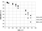
- FIG. 4 is a graph of the capacity appearance rate (A) in Table 1.
- FIG. 1 is a schematic diagram (front sectional view) showing an example of an electrolytic capacitor according to the present embodiment.
- FIG. 2A is an explanatory diagram illustrating an example of a capacitor element in an electrolytic capacitor according to this embodiment.
- FIG. 5A is a graph of the change in capacity appearance rate (C) when the viscosity increases by 10% in Table 2.
- FIG. 5B is a graph in which an approximate straight line is displayed on the scatter diagram of FIG. 5A.
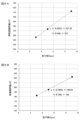
- FIG. 6A is a graph in which an approximate straight line is displayed in a scatter diagram showing the relationship between the particle diameter D of the sintered grains (powder grains) of the sintered foil and the quasi-viscosity critical value.
- FIG. 6B is a graph in which an approximate straight line is displayed in a scatter diagram showing the relationship between the particle diameter D of the sintered grains (powder grains) of the sintered foil and the viscosity critical value.
- FIG. 1 is a schematic diagram (front sectional view) showing an example of an electrolytic capacitor 1 according to the present embodiment.
- FIG. 2A is an explanatory diagram illustrating an example of the capacitor element 2 in the electrolytic capacitor 1 according to the present embodiment.
- FIG. 2B is an explanatory diagram illustrating another example of the capacitor element 2.
- 2A and 2B each schematically show an example of the basic configuration of the capacitor element 2.
- a wound type electrolytic capacitor 1 will be described as an example, but the present invention is not limited to this form, and may be, for example, a laminated type, a coin type, or the like.
- an aluminum electrolytic capacitor 1 will be described as an example, which is made of an electrode material mainly made of aluminum or an aluminum alloy and has an anode foil 8 having an oxide film 8d as a dielectric layer.
- a valve metal other than aluminum or an alloy thereof may be used as the main material.
- a capacitor element 2 is housed within an exterior material 6.
- the opening of the exterior material 6 is sealed with a sealing material 5, and the opening edge of the exterior material 6 is crimped to the sealing material 5 and sealed.
- Lead terminals 4 (anode terminal 4a and cathode terminal 4b) are passed through two through holes provided in sealing material 5, and lead wire 11 is drawn out of electrolytic capacitor 1.
- an explosion-proof valve 7, which is a pressure valve, is provided on the exterior material 6 as a safety valve, and is activated (opened) when the internal pressure of the electrolytic capacitor 1 reaches a certain level or higher, and releases the gas inside the electrolytic capacitor 1. It is designed to be explosion-proof.
- the number and position of the explosion-proof valves 7 are not limited, and they may be provided in the sealing material 5, or may be provided in both the exterior material 6 and the sealing material 5.
- the capacitor element 2 includes an anode foil 8, a cathode foil 9, and a separator 10 disposed between the anode foil 8 and the cathode foil 9, as shown in FIG. 2A.
- an anode terminal 4a and a cathode terminal 4b are attached to the anode foil 8 and the cathode foil 9, respectively.
- the electrode foils are made of an electrode material whose main material is a valve metal such as aluminum or tantalum, or an alloy thereof, and optionally has a base material 8a that supports the electrode material.
- the main material of the base material 8a is not particularly limited, a valve metal such as aluminum or tantalum or an alloy thereof can also be used for the base material 8a.
- the term "main material” used here means that the inclusion of a trace amount of impurity is allowed, as will be described later.
- the main material of the electrode material according to this embodiment is aluminum or an aluminum alloy.
- the aluminum in aluminum or aluminum alloy preferably has a purity of 99.80 [mass%] or higher from the viewpoint of preventing defects caused by impurities, and further preferably has a purity of 99.80 [mass%] or more from the viewpoint of suppressing an increase in leakage current under high temperature loads. It is preferable that it is .99 [mass%] or more.
- the aluminum alloy for example, an alloy containing one or more of elements such as silicon, iron, copper, manganese, magnesium, chromium, zinc, titanium, vanadium, gallium, nickel, boron, and zirconium may be used. I can do it. In this case, the content of each of these elements is preferably 100 [ppm by mass] or less, particularly 50 [ppm by mass] or less.
- the anode foil 8 is configured as a sintered foil
- the cathode foil 9 is configured as an etched foil, and both have an enlarged surface structure on their surfaces.
- the sintered foil of the anode foil 8 is a foil having a metal sintered body at least on its surface.
- the cathode foil 9 is constructed by etching aluminum foil, which is an electrode material, as an example, but the cathode foil 9 may also be constructed as a sintered foil. Note that the etching process may be performed by a direct current electrolysis method, an alternating current electrolysis method, or the like.
- a DC current of 500 [mA/cm 2 ] is applied in a mixed aqueous solution of hydrochloric acid and sulfuric acid (hydrochloric acid: 1 [mol/L], sulfuric acid: 3 [mol/L]) at 80 [°C].
- Etching treatment was carried out by processing for 1 [minute] and then processing for 5 [minutes] at a direct current of 100 [mA/cm 2 ] in a nitric acid aqueous solution (nitric acid: 1 [mol/L]) at 75 [°C]. It can be carried out.
- the sintered foil can be formed, for example, by a method in which a composition containing at least aluminum powder is applied to the surface of the aluminum foil that is the base material 8a, and the composition is heated and sintered.
- a method in which a composition containing at least aluminum powder is applied to the surface of the aluminum foil that is the base material 8a, and the composition is heated and sintered thereby, as shown in FIG. 2A, it is possible to form a sintered foil in which a sintered body coating 8b made of a sintered body of a composition containing aluminum powder is formed on the surface of the aluminum foil.
- the sintered body film 8b which is the electrode material, may be formed on at least one side of the aluminum foil, which is the base material 8a, facing the cathode foil 9, and is not necessarily formed on both sides of the aluminum foil, as shown in FIG. 2A. (That is, as shown in FIG.
- the "surface of the base material” in the claims may mean one side of the base material 8a. Further, the materials (main materials) of the base material 8a and the sintered body film 8b do not necessarily have to be the same. As an example, a sintered body coating 8b made of a sintered body of a composition containing aluminum alloy powder may be formed on the surface of an aluminum foil that is the base material 8a.
- the sintered foil can also be formed by heating and sintering a composition containing at least aluminum powder without having the base material 8a, and forming it into a foil shape before and after that. .
- a sintered foil consisting of a foil-shaped sintered body 8c in which a sintered body of a composition containing aluminum powder is formed into a foil shape.
- the sintered body coating 8b and the foil-shaped sintered body 8c are obtained by sintering powder grains of aluminum or aluminum alloy powder while maintaining voids between them. That is, it is a porous sintered body in which each sintered grain 8e is connected to each other while having voids to form a three-dimensional network structure.
- the sintered foil has an enlarged surface structure with a specific surface area larger than that of the etched foil, depending on the particle diameter D of the powder grains or sintered grains 8e, the thickness or porosity of the sintered body film 8b, etc.
- the electrolytic capacitor 1 according to the present embodiment can realize a larger capacitance than an electrolytic capacitor to which etched foil is applied.
- the sintered foil in FIGS. 2A and 2B may be subjected to etching treatment to further enlarge the surface.
- the particle diameter D of the powder grains of aluminum powder or the sintered grains 8e thereof the larger the specific surface area and the larger the capacitance of the sintered foil. From this, it is preferable that the particle diameter D of the powder grains of the aluminum powder or the sintered grains 8e of the aluminum powder is, for example, 5.0 [ ⁇ m] or less, and more preferably 3.0 [ ⁇ m] or less. preferable.
- the particle diameter D as used in the present application is a value in the unit [ ⁇ m] defined as follows (regardless of whether or not this definition is described, all descriptions of "particle diameter D" are the same).
- the particle diameter D [ ⁇ m] of the powder particles is the median diameter (median diameter (D 50 )) with a cumulative frequency of 50 [%] in the volume-based particle size distribution of the powder particles measured by a laser diffraction/scattering method. means.
- the particle diameter D [ ⁇ m] of the sintered particles 8e is based on the volume of the sintered particles 8e measured by observing the surface or cross section of the sintered body coating 8b or the foil-like sintered body 8c using a scanning electron microscope.
- the diameter of the observed sintered grains 8e is measured as the particle diameter.
- the sintered grains 8e may be in a state in which the sintered powder grains are melted and partially lose their shape, or in which the sintered powder grains are partially connected to each other. In that case, a portion having a substantially circular shape is approximately regarded as one sintered grain 8e, and its maximum diameter is measured as the particle diameter. On the other hand, parts whose approximately circular shape is difficult to distinguish are excluded.
- the particle diameters of a predetermined number of sintered grains 8e are measured, and the volume-based particle diameter distribution is calculated from the number-based particle diameter distribution.
- the median diameter (median diameter (D 50 )) with a cumulative frequency of 50% in the particle size distribution is obtained as the particle diameter D [ ⁇ m] of the sintered particles 8e.
- the particle diameter D of the metal powder hardly changes before and after sintering, and the particle diameter D [ ⁇ m] of the powder grain determined by the above method and the particle diameter D [ ⁇ m] of the sintered grain 8e of the powder grain are ⁇ m] is almost the same.
- the particle diameter D is defined as "the particle diameter D of the powder grains of the metal powder or the sintered grains 8e of the metal powder" because the measurement of the particle diameter D is performed on the powder grains before sintering and It is intended that any of the sintered grains 8e after sintering may be used as a sample.
- the composition containing aluminum or aluminum alloy powder may contain additives such as a binder, a solvent, a sintering aid, and a surfactant, as necessary.
- additives such as a binder, a solvent, a sintering aid, and a surfactant, as necessary.
- publicly known products or commercially available products can be used as appropriate.
- the binder includes carboxy-modified polyolefin resin, vinyl chloride resin, vinyl acetate resin, vinyl chloride/vinyl acetate copolymer resin, vinyl alcohol resin, butyral resin, vinyl fluoride resin, acrylic resin, polyester resin, urethane resin, Synthetic resins such as epoxy resins, urea resins, phenolic resins, acrylonitrile resins, nitrocellulose resins, paraffin waxes, polyethylene waxes, waxes, tars, glues, lacquers, and eyelashes. (pine resin), beeswax (beeswax), and other natural resins can be used.
- organic solvents such as ethanol, toluene, ketones, and esters can be used as the solvent.
- organic solvents such as ethanol, toluene, ketones, and esters
- the composition containing aluminum or aluminum alloy powder has moldability and shape retention properties, and the sintered body film 8b and the foil-like sintered body are formed.
- the body 8c can be formed to have an optimal thickness.
- the sintering conditions for the composition are not limited, but as an example, it may be set in a range of 560 [°C] or more and 660 [°C] or less and about 5 [hours] to 24 [hours].
- the sintering atmosphere may be a vacuum, an inert gas atmosphere such as argon gas, an air atmosphere, an oxidizing atmosphere, a reducing atmosphere, or the like.
- the pressure environment may be normal pressure, reduced pressure, or increased pressure.
- the composition contains an organic additive such as an organic binder
- an organic additive such as an organic binder
- Such pre-treatment sometimes referred to as "degreasing treatment”
- sintering treatment can evaporate the organic additives so that very little remains.
- An oxide film 8d serving as a dielectric layer is formed on the surface of the anode foil 8 configured as a sintered foil as described above by chemical conversion treatment.
- the chemical conversion treatment may be carried out by anodizing, in which the target metal is immersed in a chemical liquid tank as an anode, and a voltage is applied to form the oxide film 8d, or the target metal is simply immersed in a chemical liquid tank. It may also be carried out by immersion treatment.
- a DC current of 10 [mA/ cm 2 ] or more and 400 [mA/cm 2 ] for 5 minutes or more, the oxide film 8d can be formed.
- the cathode foil 9 is basically not subjected to chemical conversion treatment, but the surface of the cathode foil 9 is coated with a natural oxide film due to oxygen in the air. (not shown) is formed.
- the separator 10 disposed between the anode foil 8 and the cathode foil 9 to partition them may be made of, for example, paper made of natural cellulose fibers such as Manila hemp pulp, or nylon, although the structure is not particularly limited. Cloth, sheet, film, etc. made of synthetic fibers can be applied. Further, a mixed paper product, a blended product, etc. of natural fibers and synthetic fibers may be applied.
- FIG. 2 schematically shows an example of the basic configuration of the capacitor element 2 and shows one separator 10, the number is not actually limited, and as an example, as shown in FIG. 3B. , two separators (first separator 10a and second separator 10b) may be provided.
- the capacitor element 2 is impregnated with an electrolytic solution 3.
- the electrolytic solution 3 is contained in the gap between the electrode foils 8 and 9, and depending on the structure and material of the separator 10, a part of the electrolytic solution 3 is also impregnated into the separator 10.
- the electrolytic solution 3 is configured to come into contact with a dielectric layer (oxide film 8d) formed on the anode foil 8 and function as a true cathode that is substantially the opposite electrode of the anode foil 8.
- the electrolytic solution 3 does not need to be completely filled between the electrode foils 8 and 9, as long as the electrolytic solution 3 can perform the function. There may be areas where there is no data.
- the electrolytic solution 3 is a liquid component that has fluidity.
- the electrolytic solution 3 contains a solvent, a solute that is an electrolyte, and further contains predetermined additives.
- a solvent consisting only of an organic solvent, or a water-organic solvent based solvent in which a predetermined amount of water is added to an organic solvent as a main solvent can be used. Note that by using a water-organic solvent, the solubility of the electrolyte and the mobility of ions can be increased, and the specific resistance of the electrolytic solution 3 can be lowered. Furthermore, by lowering the freezing point of the solvent, electrical properties at lower temperatures can be ensured.
- a solvent consisting only of an organic solvent does not contain water in the electrolytic solution 3, which prevents the hydration reaction between the electrode foils 8 and 9 and water at high temperatures, thereby reducing the capacitor element 2. Can prevent internal pressure from increasing.
- organic solvents examples include protic solvents such as monohydric alcohols such as methyl alcohol, ethyl alcohol, propyl alcohol, and butyl alcohol; dihydric alcohols such as ethylene glycol, diethylene glycol, triethylene glycol, polyethylene glycol, and propylene glycol; Examples include trihydric alcohols such as glycerin, and derivatives thereof.
- lactone compounds such as ⁇ -butyrolactone, sulfolane, methylsulfolane, dimethylsulfolane, ethylene carbonate, propylene carbonate, pyrrolidine, 2-pyrrolidinone, N-methyl-2-pyrrolidinone, 1,3-dimethyl- Examples include 2-imidazolidinone, tetrahydrofuran, acetonitrile, N-methylformamide, N,N-dimethylformamide, nitrobenzene, and derivatives thereof. Among these, one type may be used alone, or two or more types may be used in combination. For example, both protic and aprotic solvents may be used.
- an organic acid, an inorganic acid, a composite compound of an organic acid and an inorganic acid, a derivative thereof, or a salt thereof can be used.
- one type may be used alone, or two or more types may be used in combination.
- both organic and inorganic acids may be used.
- organic acids and derivatives thereof include monocarboxylic acids such as formic acid, acetic acid, propionic acid, butyric acid, benzoic acid, caprylic acid, and derivatives thereof.
- dicarboxylic acids include oxalic acid, malonic acid, succinic acid, glutaric acid, adipic acid, fumaric acid, maleic acid, phthalic acid, azelaic acid, sebacic acid, 1,6-decanedicarboxylic acid, 5,6-decanedicarboxylic acid.
- examples include acids, 1,10-decanedicarboxylic acid, and derivatives thereof.
- hydroxycarboxylic acids include citric acid, salicylic acid, and derivatives thereof.
- examples of inorganic acids and derivatives thereof include phosphoric acid, boric acid, sulfamic acid, and derivatives thereof.
- examples of complex compounds of organic acids and inorganic acids and their derivatives include boron complexes of dicarboxylic acids or hydroxycarboxylic acids, such as borodisoxalic acid, borodimalonic acid, borodisuccinic acid, borodiadipic acid, borodimalic acid, and borodiphthalate.
- examples include acids such as borodiglycolic acid, borodiccitric acid, borodisalicylic acid, and derivatives thereof.
- salts of organic acids, inorganic acids, complex compounds of organic acids and inorganic acids, and derivatives thereof include ammonium salts, alkylammonium salts, amine salts, amidine salts, sodium salts, potassium salts, etc. Can be mentioned.
- the electrolyte may be added in an optimum amount depending on the type, as long as the desired conductivity can be ensured and it can be dissolved in the solvent.
- an organic acid, a derivative thereof, or a salt thereof may be added in an amount of about 3 [mass %] to 30 [mass %] based on the total mass of the electrolytic solution 3.
- inorganic acids, derivatives thereof, or salts thereof may be added in an amount of about 0.1 [mass %] to 15 [mass %] based on the total mass of the electrolytic solution 3.
- the above organic acid components and inorganic acid components are used as a mixture, they are added in a range of about 0.1 [mass%] to 15 [mass %] of the total mass of the electrolyte solution 3. That's fine.
- the electrolytic solution 3 may contain appropriate predetermined additives in addition to the solvent and the solute.
- additives include substances that have the function of becoming a solvent or solute, but they are usually added in relatively small amounts separately from the main solvent or solute, mainly for the purpose of effecting other functions. means.
- additives include chelate compounds, sugars, gluconic acid, nitro compounds, and the like.
- the viscosity ⁇ of the electrolytic solution 3 is set to 400 [cP] or less, and more preferably to 300 [cP].
- the viscosity ⁇ in this application is the viscosity ⁇ measured in electrolyte 3 at 25 [°C] using a vibratory viscometer, and is a value in the unit [cP] (hereinafter, regardless of whether or not this definition is stated) , the same for all "viscosity ⁇ " descriptions).
- the sintered foil composed of relatively small sintered grains 8e can be used regardless of the size of the sintered grains 8e. ), the capacitance appears stably.
- the viscosity ⁇ is set to 400 [cP] or less for a sintered foil in which the sintered grains 8e are, for example, 5.0 [ ⁇ m] or 3.0 [ ⁇ m].
- the foil capacitance can be made to appear at an appearance rate of over 80%.
- the foil capacitance can be made to appear at an appearance rate exceeding 90 [%].
- the particle diameter D of the powder grains of the aluminum powder or the sintered grains 8e thereof is reduced to, for example, 5.0 [ ⁇ m] or less, more preferably 3.0 [ ⁇ m] or less.
- the capacitance can be made sufficiently large, and such a large capacitance can be made to appear stably.
- the viscosity ⁇ of the electrolytic solution 3 can be adjusted to a desired value by adjusting the combination of the electrolytic solution components (solvent component and solute component) (e.g., selection of substances and adjustment of their mixing ratio), concentration, etc.
- the viscosity can be adjusted to ⁇ .
- setting the viscosity ⁇ of the electrolytic solution 3 to, for example, 400 [cP] or less means that the electrolytic solution 3 impregnated into the capacitor element 2 is set to the viscosity ⁇ in the manufacturing process of the electrolytic capacitor 1. means.
- the viscosity ⁇ of the electrolytic solution 3 may absorb moisture in the capacitor element 2 immediately after impregnation and decrease slightly, or increase slightly due to evaporation of moisture over time.
- the viscosity ⁇ of the electrolytic solution 3 is considered to be almost the same as that when impregnated. It will be done.
- the viscosity ⁇ of the electrolyte 3 is set to 400 [cP] or less
- the viscosity ⁇ of the electrolyte 3 in the electrolytic capacitor 1 is set to 400 [cP] or less. It can also be stipulated that It should be noted that when measuring the viscosity ⁇ of the electrolytic solution 3, there is also a possibility that some components will volatilize and the viscosity ⁇ will change slightly, but this change is very small and poses no problem.
- the viscosity ⁇ of the electrolytic solution 3 increases due to the progress of water evaporation.
- the capacitance may decrease due to an imbalance between the properties of the electrolytic solution 3 (viscosity ⁇ ) and the structure of the sintered particles 8e (particle diameter D). Therefore, in order to stabilize the capacitance of the electrolytic capacitor 1 against deterioration over time after use, the viscosity ⁇ of the electrolytic solution 3 is determined in relation to the particle diameter D of the powder grains of the aluminum powder or its sintered grains 8e. , it is preferable to set it more strictly as follows.
- the viscosity ⁇ of the electrolytic solution 3 at 25 [° C.] satisfies the following inequality (1), and more preferably satisfies the following inequality (2). ⁇ 9.438D+227...(1) ⁇ 6.726D+162 (2)
- D in the above inequality (1) and inequality (2) is the particle diameter D of the powder grains of the metal powder (here, the aluminum powder) or the sintered grains 8e of the metal powder (here, the aluminum powder). [ ⁇ m], and the particle size D is the particle size distribution based on the volume of the powder particles measured by laser diffraction/scattering method or the sintered particles 8e measured by observation with a scanning electron microscope. Means the cumulative median diameter of 50%.
- a volume-based particle size distribution is calculated from a number-based particle size distribution.
- the viscosity ⁇ value in the region where the decrease in is relatively small was defined as the "quasi-critical viscosity value.”
- the viscosity critical value is defined as the viscosity ⁇ value when the change is 0 [%] based on the approximate straight line of the capacity appearance rate change
- the quasi-viscosity critical value is defined as the value at which the change is allowed.
- the viscosity ⁇ value was defined as 1 [%].
- the above inequality (1) is a parameter that allows the viscosity ⁇ of the electrolyte 3 to be set below the quasi-viscosity critical value
- the above inequality (2) is a parameter that allows the viscosity ⁇ of the electrolyte 3 to be set below the viscosity critical value.
- the viscosity critical value and quasi-critical viscosity value are calculated for the sintered foil composed of sintered grains 8e having different particle diameters D, and the particle diameter D [ ⁇ m] and the viscosity critical value [cP] or the quasi-viscosity critical value are calculated.
- Inequalities based on approximate straight lines calculated by plotting the relationship with [cP] on a graph are the above-mentioned inequality (1) and inequality (2).
- the target viscosity ⁇ range of the electrolytic solution 3 becomes clear from the particle diameter D of the sintered grains 8e or powder grains constituting the sintered foil.
- the electrolytic capacitor 1 will be able to withstand the aging deterioration (increase in viscosity ⁇ ) caused by the use of the electrolytic capacitor 1 due to the large static characteristic of sintered foil. It is possible to make capacitance appear stably over a long period of time with almost no decrease in capacitance, and if the viscosity critical value (inequality (2)) is satisfied, capacitance can be made to appear stably over a long period of time. be able to. As a result, the life of the electrolytic capacitor 1 can be extended.
- the viscosity ⁇ of the electrolytic solution 3 is preferably 2 [cP] or more, and more preferably 10 [cP] or more, as an example. , 30 [cP] or more is even more preferable.
- the anode foil 8 of the electrode foils 8 and 9 is configured as a sintered foil composed of sintered particles 8e having a predetermined particle diameter D, or the electrolytic The liquid 3 may be configured to have predetermined properties, but other than this configuration, the basic fabrication of the capacitor element 2 and the assembly of the electrolytic capacitor 1 can be performed in accordance with conventional examples.
- the wound type electrolytic capacitor 1 according to the present embodiment has a lead terminal 4 (anode terminal 4a) on a sintered foil on which an oxide film 8d (not shown in FIG. 3B) is formed by chemical conversion treatment.
- a separator 10 (a first separator 10a and a second separator 10b) is placed between an anode foil 8 that has been joined by crimping or the like and a cathode foil 9 that has a lead terminal 4 (cathode terminal 4b) joined to the etched foil by crimping or the like. ), and as shown in FIGS. 3A and 3B, these are wound to form a substantially cylindrical shape.
- the obtained wound body is subjected to chemical conversion treatment again as necessary, it is immersed in three baths of electrolytic solution having the composition according to the present embodiment, so that the electrolytic solution is filled into the gap between both electrode foils 8 and 9. 3 can be introduced (impregnated) to manufacture the capacitor element 2.
- the lead wire 11 is connected to the lead terminal 4 at an appropriate time (illustration of the lead terminal 4 and the lead wire 11 is omitted in FIG. 3A).
- the electrolytic solution 3 may be introduced under reduced pressure if necessary.
- the capacitor element 2 is housed in the exterior material 6, and the sealing material 5 is placed in the opening of the exterior material 6 to seal it.
- the lead terminal 4 (anode terminal 4a and cathode terminal 4b) is passed through two through holes provided in the sealing material 5 and pulled out.
- the opening edge of the exterior material 6 is crimped to the sealing material 5 to seal it.
- an aging treatment may be performed in which a voltage is applied for a predetermined period of time under high temperature conditions to repair defects in the oxide film 8d that occur when cutting or winding the foil.
- a sintered foil was produced by sintering aluminum powder having a particle diameter D of 3.0 [ ⁇ m], 5.0 [ ⁇ m], or 9.0 [ ⁇ m].
- sintered foil composed of 3.0 [ ⁇ m] sintered grains (powder grains) will be referred to as "3.0 [ ⁇ m] foil”
- sintered foil composed of 5.0 [ ⁇ m] sintered grains (powder grains) The sintered foil composed of sintered granules (powder grains) of 9.0 [ ⁇ m] is referred to as "5.0 [ ⁇ m] foil” and the sintered foil composed of 9.0 [ ⁇ m] sintered grains (powder grains) as "9.0 [ ⁇ m] foil”. It may be written.
- the particle diameter D of the powder particles is the cumulative median diameter of 50% in the volume-based particle diameter distribution measured by a laser diffraction/scattering method.
- the sintered foil for evaluation produced in this way has a capacitance for medium-high voltage anode chemical foils (voltage classification: rated film withstand voltage 170 [V] or more) in accordance with the description of the above standard (EIAJ RC-2364A).
- Foil capacitance (electrostatic capacity) [ ⁇ F/cm 2 ] at 120 [Hz] was measured using an aqueous ammonium pentaborate solution corresponding to measurement solution “C” as measurement solution (1).
- each electrolyte solution consisting of a predetermined component adjusted to each viscosity ⁇ shown in Table 1 was used as the measurement solution (2) instead of the measurement solution (1), and the electrolyte solution was similarly heated at 120 [Hz].
- the foil capacitance (electrostatic capacitance) [ ⁇ F/cm 2 ] was measured.
- the viscosity ⁇ is the viscosity ⁇ [cP] measured with an electrolytic solution at 25 [° C.] using a vibratory viscometer. Specifically, a vibratory viscometer (trade name: Viscomate VM-1A) manufactured by Sekonic Co., Ltd. was used.
- the foil capacitance [ ⁇ F/cm 2 ] is the foil capacitance value [ ⁇ F/cm 2 ] per unit area (1 cm 2 ) calculated from the measured foil capacitance value [ ⁇ F].
- Capacity appearance rate (A) Foil capacitance value in measurement solution (2) [ ⁇ F/cm 2 ] / Foil capacitance value in measurement solution (1) [ ⁇ F/cm 2 ]
- the capacity appearance rate (A) represents the stability (or instability) of the capacitance in relation to the properties (viscosity ⁇ ) of the electrolytic solution of the sintered foil, and the value is 1 ([%] in terms of unit: 100[ %]), the more stable the capacitance appears.
- the capacity appearance rate (A) is converted into [%] and shown in Table 1 and FIG. 4 (However, the (A) value [%] in Table 1 is a value rounded to the second decimal place).
- the capacity appearance rate (A) approaches 100 [%] regardless of the particle diameter D of the sintered grains (powder grains), and the electrostatic The capacity has stabilized.
- the viscosity ⁇ of the electrolytic solution is 400 [cP] or less, the decrease in capacitance is reliably suppressed to less than -20 [%] (the capacitance appearance rate (A) exceeds 80 [%]).
- the viscosity ⁇ of the electrolytic solution was 300 [cP] or less, the decrease in capacitance was suppressed to less than -10 [%] (the capacity appearance rate (A) exceeded 90 [%]).
- the viscosity ⁇ of the electrolytic solution is set to 400 [cP] or less, more preferably 300 [cP] or less, the foil capacitance can stably appear. It is preferable that it can be done. Furthermore, when the particle diameter D of the sintered grains (powder grains) is 5.0 [ ⁇ m] or less, more preferably 3.0 [ ⁇ m] or less, the foil capacity itself is improved and a larger electrostatic charge is generated. It is more preferable because it is possible to realize the capacity and to make the capacity appear stably.
- the change in capacity appearance rate (C) is independent of the particle diameter D of the sintered grains (powder grains); It can be seen that even in foil forming, there are a viscosity ⁇ region (stable region) where the capacitance hardly changes and a viscosity ⁇ region (unstable region) where the capacitance decreases relatively greatly. Further, from FIG. 5A, it can be confirmed that the boundary value between the stable region and the unstable region (hereinafter referred to as "viscosity critical value”) exists around 200 [cP].
- FIG. 5B is a graph showing the calculated approximate straight line on the scatter diagram of FIG. 5A.
- the calculated value of the vertical axis intercept was 2.48 [%] (rounded to the second decimal place). Also, the value of the horizontal axis intersection is 182.6 [cP] for 3.0 [ ⁇ m] foil, 195.1 [cP] for 5.0 [ ⁇ m] foil, and 222.7 for 9.0 [ ⁇ m] foil. [cP] (each rounded to the second decimal place).
- This horizontal axis intersection represents the viscosity ⁇ value [cP] when the capacity appearance rate change (C) becomes 0 [%] on the approximate straight line, and this was defined as the above-mentioned "viscosity critical value".
- the viscosity ⁇ value [cP] when the capacity appearance rate change (C) becomes -1 [%] on the approximate straight line was calculated, and this was defined as the "quasi-viscosity critical value".
- the semi-critical viscosity values are 256.2 [cP] for 3.0 [ ⁇ m] foil, 273.8 [cP] for 5.0 [ ⁇ m] foil, and 312.5 [cP] for 9.0 [ ⁇ m] foil. (Rounded to the second decimal place).
- the viscosity critical value is divided into the viscosity ⁇ region (stable region) where the capacitance hardly changes when the viscosity ⁇ increases by a predetermined value, and the viscosity ⁇ region where the capacitance decreases relatively significantly (unstable region). It represents the viscosity ⁇ value at the boundary with the stable region), and was defined as the viscosity ⁇ value when the capacity appearance rate change (C) becomes 0 [%] on the approximate straight line.
- the quasi-viscosity critical value is defined as the viscosity ⁇ value when the capacitance appearance rate change (C) is -1 [%] allowed on the approximate straight line. It represents the viscosity ⁇ value in a region near the critical value where the decrease in capacitance is relatively small.
- the viscosity ⁇ [cP] of the electrolytic solution is determined by the inequality ( 1)
- the viscosity ⁇ is set near the critical viscosity value or in a stable region by setting it to a state that satisfies “ ⁇ 9.438D+227” (that is, below the quasi-viscosity critical value).
- the viscosity ⁇ [cP] of the electrolytic solution satisfies inequality (2) “ ⁇ 6.726D+162” where the particle diameter D of the sintered grains (powder grains) is a variable based on the approximate linear equation (2).
- the particle diameter D [ ⁇ m] value should be the value to the first decimal place (if measured to the second decimal place or below, round to the first decimal place).
- the viscosity ⁇ value [cP] is calculated as an integer value by rounding off the solution to the first decimal place.
Abstract
電極箔として少なくともその表面に金属焼結体を有する焼結箔が適用された電解コンデンサにおいて、焼結箔特有の比較的大きな静電容量を安定して出現可能な電解コンデンサおよびその製造方法を提供することを課題とする。解決手段として、本発明に係る電解コンデンサ(1)は、誘電体層が形成された陽極箔(8)と、陰極箔(9)と、前記陽極箔(8)と前記陰極箔(9)との間に配設されたセパレータ(10)と、を有するコンデンサ素子(2)と、前記コンデンサ素子(2)内に含浸された電解液(3)と、を備える電解コンデンサであって、前記陽極箔(8)または前記陰極箔(9)は、金属粉末を含有する組成物の焼結体が箔状に形成されてなり(箔状焼結体(8c)からなり)、または、前記焼結体からなる焼結体皮膜(8b)が基材の表面に形成されてなり、前記電解液(3)の25[℃]における粘度μ[cP]が、400[cP]以下である。
Description
本発明は電解コンデンサおよび電解コンデンサの製造方法に関する。
誘電体層としての酸化皮膜等が形成された陽極箔と陰極箔との間にセパレータが配設されたコンデンサ素子内に、電解液が含浸された電解コンデンサが知られている。
従来、電解コンデンサにおいては、高容量化を実現するために、電極箔には、拡面処理により比表面積を増大させた金属箔が用いられている。拡面処理は、一般的には、電気化学的なエッチング処理によって金属箔の表面に多数の細孔を形成させることが行われる(以下、エッチング処理が施された金属箔を「エッチング箔」と表記する場合がある)。しかしながら、エッチング処理による比表面積の増大には限界があり、高まる高容量化要求を満たせなくなりつつある。また、エッチング処理には、環境負荷や経済負担が比較的大きい塩酸等の薬剤を使用することや、金属箔を電気化学的に溶解させることで箔強度の低下を招くことがあるといった欠点がある。
こうしたことを踏まえて、特許文献1(特開2008-98279号公報)には、基材(当該文献では、アルミニウム箔)の表面に、金属粉末(当該文献では、アルミニウム粉末)を含有する組成物を塗布し、加熱して焼結させた焼結体皮膜を形成させることで、比表面積を増大させる拡面処理法が記載されている(以下、少なくともその表面に金属焼結体を有する箔を「焼結箔」と表記する場合がある)。
特許文献1に例示される焼結箔によれば、従来のエッチング箔と比較して環境負荷や経済負担を低減することができる。また、製造工程における箔強度の低下を防止でき、さらに、金属粉末の粉末粒またはその焼結粒の粒子径や、焼結体皮膜の厚さ等を調整することで、比較的大きな静電容量が実現できる。しかしながら、電解液の性状によっては、静電容量が安定せず、十分に出現させられないことがあった。
本発明は、上記事情に鑑みてなされ、電極箔として少なくともその表面に金属焼結体を有する焼結箔が適用された電解コンデンサにおいて、焼結箔特有の比較的大きな静電容量を安定して出現可能な電解コンデンサおよびその製造方法を提供することを目的とする。
本発明は、一実施形態として以下に記載するような解決手段により、前記課題を解決する。
本発明に係る電解コンデンサは、誘電体層が形成された陽極箔と、陰極箔と、前記陽極箔と前記陰極箔との間に配設されたセパレータと、を有するコンデンサ素子と、前記コンデンサ素子内に含浸された電解液と、を備える電解コンデンサであって、前記陽極箔または前記陰極箔は、金属粉末を含有する組成物の焼結体が箔状に形成されてなり、または、前記焼結体からなる焼結体皮膜が基材の表面に形成されてなり、前記電解液の25[℃]における粘度μ[cP]が、400[cP]以下であることを特徴とする。
また、本発明に係る電解コンデンサの製造方法は、誘電体層が形成された陽極箔と、陰極箔と、前記陽極箔と前記陰極箔との間に配設されたセパレータと、を有するコンデンサ素子と、前記コンデンサ素子内に含浸された電解液と、を備える電解コンデンサの製造方法であって、前記陽極箔および前記陰極箔の少なくとも一方を、金属粉末を含有する組成物の焼結体を箔状に形成して構成し、または、前記焼結体からなる焼結体皮膜を基材の表面に形成させて構成し、前記電解液の25[℃]における粘度μ[cP]を、400[cP]以下に調整することを特徴とする。
これによれば、焼結箔との関係で電解液の性状(粘度μ)が適切な状態に構成されることで、焼結箔特有の比較的大きな静電容量を安定して出現させることができる。
本発明に係る電解コンデンサは、前記金属粉末の粉末粒または該金属粉末の焼結粒の粒子径D[μm]が、5.0[μm]以下であることが好ましい。また、本発明に係る電解コンデンサの製造方法は、前記金属粉末の粉末粒または該金属粉末の焼結粒の粒子径D[μm]を、5.0[μm]以下に調整することが好ましい。ただし、粒子径Dは、レーザ回折・散乱法により測定される前記粉末粒、または走査型電子顕微鏡による観察により測定される前記焼結粒の体積基準の粒子径分布における累積50[%]の中位径を意味する。なお、焼結粒の粒子径分布においては、個数基準の粒子径分布から体積基準の粒子径分布を計算する。
これによれば、微細な焼結粒によって比表面積を増大させることで、より大きな静電容量を実現できる。また、そのような大きな静電容量を安定して出現させることができる。
また、本発明に係る電解コンデンサは、前記電解液の25[℃]における粘度μ[cP]が、さらに以下の式(1)を満たすとより好ましい。
μ≦9.438D+227 ・・・(1)
μ≦9.438D+227 ・・・(1)
また、本発明に係る電解コンデンサの製造方法は、前記電解液の25[℃]における粘度μ[cP]を、さらに以下の式(1)を満たすように調整するとより好ましい。
μ≦9.438D+227 ・・・(1)
μ≦9.438D+227 ・・・(1)
ただし、上記の式(1)におけるDは、前記金属粉末の粉末粒または該金属粉末の焼結粒の粒子径D[μm]を意味し、該粒子径Dは、レーザ回折・散乱法により測定される前記粉末粒、または走査型電子顕微鏡による観察により測定される前記焼結粒の体積基準の粒子径分布における累積50[%]の中位径を意味する。なお、焼結粒の粒子径分布においては、個数基準の粒子径分布から体積基準の粒子径分布を計算する。
これによれば、例えば電解コンデンサの使用による経時劣化(粘度μ上昇)等に対しても、焼結箔に特有の大きな静電容量を殆ど低下させることなく、長期に亘って安定して出現させることができる。
本発明によれば、焼結箔が適用された電解コンデンサにおいて、焼結箔特有の比較的大きな静電容量を安定して出現させることができる。
以下、図面を参照して、本発明を実施するための形態について詳しく説明する。図1は、本実施形態に係る電解コンデンサ1の例を示す概略図(正面断面図)である。図2Aは、本実施形態に係る電解コンデンサ1におけるコンデンサ素子2の例を説明する説明図である。図2Bは、当該コンデンサ素子2の他の例を説明する説明図である。図2Aおよび図2Bは、いずれもコンデンサ素子2の基本構成の例を模式的に示している。以下、一実施形態として、巻回型の電解コンデンサ1を例にして説明するが、この形態に限定されず、例えば、積層型、コイン型等でもよい。また、一実施形態として、アルミニウムまたはアルミニウム合金を主材料とする電極材からなり、酸化皮膜8dを誘電体層とする陽極箔8を有するアルミニウム電解コンデンサ1を例にして説明するが、この形態に限定されず、例えば、アルミニウム以外の弁金属またはその合金を主材料としてもよい。
本実施形態に係る電解コンデンサ1は、図1に示すように、コンデンサ素子2が外装材6内に収容されている。外装材6の開口部が封止材5で封止されると共に、外装材6の開口縁が封止材5に加締められて密封されて構成されている。封止材5に設けられた二箇所の貫通穴にリード端子4(陽極端子4aおよび陰極端子4b)が通されてリード線11が電解コンデンサ1外へ引き出されている。なお、外装材6には安全弁として圧力弁である防爆弁7が設けられ、電解コンデンサ1の内圧が一定以上に達した際に作動し(開弁し)、電解コンデンサ1内のガスを放出して防爆されるようになっている。防爆弁7の数および位置は限定されず、封止材5に設けられてもよく、外装材6および封止材5の両方に設けられてもよい。
続いて、本実施形態に係るコンデンサ素子2は、図2Aに示すように、陽極箔8と、陰極箔9と、陽極箔8と陰極箔9との間に配設されたセパレータ10と、を備えている。なお、陽極箔8および陰極箔9のそれぞれに陽極端子4aおよび陰極端子4bが取り付けられている。
電極箔(陽極箔8および陰極箔9)は、アルミニウム、タンタル等の弁金属またはその合金を主材料とする電極材からなり、さらに電極材を支持する基材8aを任意に有している。基材8aの主材料は特に限定されないが、基材8aもまたアルミニウム、タンタル等の弁金属またはその合金を用いることができる。なお、ここで材料を「主材料」としているのは、後述のように微量の不純物の含有を許容するという意味である。
本実施形態に係る電極材は、アルミニウムまたはアルミニウム合金が主材料とされている。アルミニウムまたはアルミニウム合金におけるアルミニウムは、不純物に起因する不具合を防止する観点から純度が99.80[質量%]以上であることが好ましく、さらに高温負荷に対する漏れ電流の増大を抑制する観点から純度が99.99[質量%]以上であることが好ましい。また、アルミニウム合金は、例えば、ケイ素、鉄、銅、マンガン、マグネシウム、クロム、亜鉛、チタン、バナジウム、ガリウム、ニッケル、ホウ素、ジルコニウム等の元素のうち一種類または二種類以上を含む合金を用いることができる。この場合、これらの元素の含有量は、それぞれ100[質量ppm]以下、特に50[質量ppm]以下であることが好ましい。
本実施形態に係る電極箔8、9は、陽極箔8が、焼結箔として構成され、陰極箔9が、エッチング箔として構成され、どちらも表面に拡面構造を有している。陽極箔8の焼結箔は、少なくともその表面に金属焼結体を有する箔である。一方、陰極箔9は、一例として、電極材であるアルミニウム箔にエッチング処理が施されて構成されるが、陰極箔9もまた焼結箔として構成されてもよい。なお、エッチング処理は、直流電解法または交流電解法等によって行われればよい。一例として、直流電解法では、80[℃]の塩酸および硫酸の混合水溶液(塩酸:1[mol/L]、硫酸:3[mol/L])中で、直流電流500[mA/cm2]で1[分]処理し、次いで75[℃]の硝酸水溶液(硝酸:1[mol/L])中で、直流電流100[mA/cm2]で5[分]処理することで、エッチング処理を行うことができる。
これに対して、焼結箔は、一例として、基材8aであるアルミニウム箔の表面に少なくともアルミニウム粉末を含有する組成物を塗布し、加熱して焼結させる方法によって形成することができる。これにより、図2Aに示すように、アルミニウム箔の表面にアルミニウム粉末を含有する組成物の焼結体からなる焼結体皮膜8bが形成された焼結箔を形成することができる。ただし、電極材である焼結体皮膜8bは、基材8aであるアルミニウム箔の少なくとも陰極箔9と対向する片面に形成されていればよく、必ずしも、図2Aに示すように、アルミニウム箔の両面(すなわち、図3Bに示すように、アルミニウム箔の表面全体)に形成されていなくてもよい。したがって、特許請求の範囲の「基材の表面」は、基材8aの片面を意味する場合がある。また、基材8aおよび焼結体皮膜8bの材料(主材料)は必ずしも一致しなくてもよい。一例として、基材8aであるアルミニウム箔の表面にアルミニウム合金粉末を含有する組成物の焼結体からなる焼結体皮膜8bが形成されてもよい。
また、焼結箔は、他の例として、基材8aを有することなく、少なくともアルミニウム粉末を含有する組成物を加熱して焼結させ、その前後で箔状にする方法によって形成することもできる。これにより、図2Bに示すように、アルミニウム粉末を含有する組成物の焼結体が箔状に形成された箔状焼結体8cからなる焼結箔を形成することができる。
焼結体皮膜8bおよび箔状焼結体8cは、図2Aおよび図2Bに示すように、アルミニウムまたはアルミニウム合金粉末の粉末粒同士が互いに空隙を維持しながら焼結したものである。すなわち、各焼結粒8eが空隙を有しながら繋がって三次元網目構造に形成された多孔質焼結体である。当該焼結箔は、粉末粒もしくは焼結粒8eの粒子径Dや、焼結体皮膜8bの厚さもしくは空隙率等によっては、その表面にエッチング箔を上回る比表面積の拡面構造を有する。その結果、本実施形態に係る電解コンデンサ1は、エッチング箔が適用された電解コンデンサを上回る大きな静電容量を実現できる。ただし、図2Aおよび図2Bの焼結箔にエッチング処理が施されて、さらに拡面化されてもよい。
なお、一例として、一般に、アルミニウム粉末の粉末粒またはその焼結粒8eの粒子径Dが小さい程、比表面積が増大されて焼結箔の静電容量が大きくなる。このことから、アルミニウム粉末の粉末粒または当該アルミニウム粉末の焼結粒8eの粒子径Dが、例えば5.0[μm]以下であることが好ましく、3.0[μm]以下であることがより好ましい。
ここで、本願でいう粒子径Dは、以下のように定義される単位[μm]の値である(本定義記載の有無に関わらず、全ての「粒子径D」の記載で同じ)。粉末粒の粒子径D[μm]は、レーザ回折・散乱法により測定される粉末粒の体積基準の粒子径分布における頻度の累積が50[%]の中位径(メジアン径(D50))を意味する。また、焼結粒8eの粒子径D[μm]は、焼結体皮膜8bまたは箔状焼結体8cの表面または断面を走査型電子顕微鏡による観察により測定される焼結粒8eの体積基準の粒子径分布における頻度の累積が50[%]の中位径(メジアン径(D50))を意味する。観察される焼結粒8eは、その直径を粒子径として測定する。ただし、焼結粒8eは、焼結した粉末粒が溶融して形状が一部崩れた状態、あるいは焼結した粉末粒同士が一部繋がった状態となっていることがある。その場合は、略円形状を有する部位を近似的に一粒の焼結粒8eと見なして、その最大径を粒子径として測定する。一方、略円形状が判別困難な部位は除外する。所定数の焼結粒8eの粒子径を測定し、これらの個数基準の粒子径分布から体積基準の粒子径分布を計算する。そして、当該粒子径分布における頻度の累積が50[%]の中位径(メジアン径(D50))を、焼結粒8eの粒子径D[μm]として得る。なお、焼結前後で金属粉末の粒子径Dが変化することは殆どなく、上記の方法で求められる粉末粒の粒子径D[μm]と、当該粉末粒の焼結粒8eの粒子径D[μm]とは殆ど同じである。つまり、本願において粒子径Dを「金属粉末の粉末粒または当該金属粉末の焼結粒8eの粒子径D」と規定しているのは、粒子径Dの測定を、焼結前の粉末粒および焼結後の焼結粒8eのいずれを試料にして行ってもよいことを意図している。
焼結箔の形成に際して、アルミニウムまたはアルミニウム合金粉末を含有する組成物には、必要に応じてバインダ、溶媒、焼結助剤、界面活性剤等の添加物を含有させてもよい。これらの添加物は適宜公知品や市販品を用いることができる。一例として、バインダには、カルボキシ変性ポリオレフィン樹脂、塩化ビニル樹脂、酢酸ビニル樹脂、塩化ビニル・酢酸ビニル共重合樹脂、ビニルアルコール樹脂、ブチラール樹脂、フッ化ビニル樹脂、アクリル樹脂、ポリエステル樹脂、ウレタン樹脂、エポキシ樹脂、尿素樹脂、フェノール樹脂、アクリロニトリル樹脂、ニトロセルロース樹脂、パラフィンワックス、ポリエチレンワックス等の合成樹脂や、ろう(蝋)、タール(乾留液)、にかわ(膠)、うるし(漆)、まつやに(松脂)、みつろう(蜜蝋)等の天然樹脂等を用いることができる。また、一例として、溶媒には、水の他、エタノール、トルエン、ケトン類、エステル類等の有機溶媒を用いることができる。これらの添加物のうち、例えばバインダおよび/または溶媒を含有させることで、アルミニウムまたはアルミニウム合金粉末を含有する組成物が成形性および保形性を有して、焼結体皮膜8bおよび箔状焼結体8cを最適な厚さに形成することができる。これらの添加物の種類や含有量を調整することで、焼結体皮膜8bおよび箔状焼結体8cの空隙率や当該添加物の残存程度を調整できる。これにより、電解コンデンサ1の静電容量を調整することができる。
組成物の焼結条件は限定されないが、一例として、560[℃]以上660[℃]以下で5[時間]から24[時間]程度までの範囲で設定するとよい。焼結雰囲気は、真空、アルゴンガス等の不活性ガス雰囲気、大気雰囲気、酸化雰囲気、還元雰囲気等のいずれでもよい。圧力環境も、常圧下、減圧下および加圧下のいずれでもよい。
また、組成物中に有機バインダ等の有機添加物を含有する場合、一例として、焼結に先立って予め100[℃]以上600[℃]以下で5[時間]以上の加熱を行うとよい。このような前処理(「脱脂処理」と呼称されることがある)および焼結処理によって有機添加物を蒸発させて殆ど残存させないようにすることができる。
以上のような焼結箔として構成される陽極箔8の表面には、化成処理によって、誘電体層としての酸化皮膜8dが形成されている。化成処理は、一例として、対象金属を陽極として化成液槽に浸漬した状態で電圧を印加して酸化皮膜8dを形成する陽極酸化処理によって行われてもよく、または対象金属を単に化成液槽に浸漬する処理によって行われてもよい。一例として、陽極酸化処理では、30[℃]以上100[℃]以下のほう酸水溶液(ほう酸:0.01[mol/L]以上5[mol/L]以下)中で、直流電流10[mA/cm2]以上400[mA/cm2]で5[分]以上処理することで、酸化皮膜8dを形成させることができる。一方、本実施形態に係る有極性の電解コンデンサ1においては、基本的に陰極箔9に対しては化成処理が行われないが、陰極箔9の表面には、空気中の酸素によって自然酸化皮膜(不図示)が形成されている。
また、陽極箔8と陰極箔9との間に配設されてこれらを仕切るセパレータ10は、特に構成は限定されないが、一例として、マニラ麻パルプ等の天然のセルロース繊維からなる紙や、ナイロン等の合成繊維で形成された布、シート、フィルム等を適用することができる。また、天然繊維と合成繊維との混抄品、混紡品等が適用されてもよい。なお、図2には、コンデンサ素子2の基本構成の例を模式的に示し、セパレータ10を一枚示しているが、実際にはその数は限定されず、一例として、図3Bに示すように、二枚(第1のセパレータ10aおよび第2のセパレータ10b)設けられてもよい。
また、コンデンサ素子2内には電解液3が含浸されている。電解液3は、両電極箔8、9間における空隙に含まれており、また、セパレータ10の構成や材料によっては、電解液3の一部がセパレータ10内にも含浸されている。電解液3は、陽極箔8に形成された誘電体層(酸化皮膜8d)に接触して、実質的に陽極箔8の対極をなす真の陰極として機能するように構成されている。ただし、電解液3は、当該機能が発揮できる範囲であれば、両電極箔8、9間に完全に充満していなくてもよく、両電極箔8、9間に電解液3が充満していない領域が存在していてもよい。
電解液3は、流動性を有する液状成分である。電解液3は、溶媒と、電解質である溶質とを含有し、さらに所定の添加剤を含有している。溶媒には、有機溶媒のみからなる溶媒、または、有機溶媒を主溶媒として、これに所定量の水を添加した水-有機溶媒系の溶媒等を適用することができる。なお、水-有機溶媒系の溶媒によれば、電解質の溶解能およびイオンの移動度を大きくして、電解液3の比抵抗を低くすることができる。また、溶媒の凝固点を低下させて、それより低温での電気特性を確保できる。一方、有機溶媒のみからなる溶媒によれば、電解液3中に水を含有しないことから、高温下での電極箔8、9と水との水和反応を防止してこれによるコンデンサ素子2の内圧上昇を防止できる。
有機溶媒としては、一例として、プロトン性溶媒として、メチルアルコール、エチルアルコール、プロピルアルコール、ブチルアルコール等の一価アルコール、エチレングリコール、ジエチレングリコール、トリエチレングリコール、ポリエチレングリコール、プロピレングリコール等の二価アルコール、グリセリン等の三価アルコール等や、これらの誘導体等が挙げられる。また、非プロトン性溶媒として、γ-ブチロラクトン等のラクトン化合物、スルホラン、メチルスルホラン、ジメチルスルホラン、エチレンカーボネート、プロピレンカーボネート、ピロリジン、2-ピロリジノン、N-メチル-2-ピロリジノン、1,3-ジメチル-2-イミダゾリジノン、テトラヒドロフラン、アセトニトリル、N-メチルホルムアミド、N,N-ジメチルホルムアミド、ニトロベンゼン等や、これらの誘導体等が挙げられる。これらのうち、一種類が単独で用いられてもよく、二種類以上が混合されて用いられてもよい。例えば、プロトン性溶媒および非プロトン性溶媒が共に用いられてもよい。
また、電解質である溶質には、有機酸、無機酸、有機酸と無機酸との複合化合物、もしくはこれらの誘導体、またはこれらの塩を適用することができる。これらのうち、一種類が単独で用いられてもよく、二種類以上が混合されて用いられてもよい。例えば、有機酸および無機酸が共に用いられてもよい。
有機酸およびその誘導体としては、一例として、モノカルボン酸として、蟻酸、酢酸、プロピオン酸、酪酸、安息香酸、カプリル酸等や、これらの誘導体が挙げられる。また、ジカルボン酸として、シュウ酸、マロン酸、コハク酸、グルタル酸、アジピン酸、フマル酸、マレイン酸、フタル酸、アゼライン酸、セバシン酸、1,6-デカンジカルボン酸、5,6-デカンジカルボン酸、1,10-デカンジカルボン酸等や、これらの誘導体が挙げられる。また、ヒドロキシカルボン酸として、クエン酸、サリチル酸等や、これらの誘導体が挙げられる。また、無機酸およびその誘導体としては、一例として、リン酸、ほう酸、スルファミン酸等や、これらの誘導体が挙げられる。また、有機酸と無機酸との複合化合物およびその誘導体としては、ジカルボン酸またはヒドロキシカルボン酸のホウ素錯体等に例示され、一例として、ボロジシュウ酸、ボロジマロン酸、ボロジコハク酸、ボロジアジピン酸、ボロジマレイン酸、ボロジフタル酸、ボロジグリコール酸、ボロジクエン酸、ボロジサリチル酸等や、これらの誘導体が挙げられる。
また、有機酸、無機酸、有機酸と無機酸との複合化合物、およびこれらの誘導体の塩としては、一例として、アンモニウム塩、アルキルアンモニウム塩、アミン塩、アミジン塩、ナトリウム塩、カリウム塩等が挙げられる。
電解質は、所望の電導度が確保できて且つ溶媒に溶かすことができる範囲で、種類に応じた最適な量が添加されればよい。一例として、有機酸もしくはその誘導体またはそれらの塩では、電解液3全質量の3[質量%]~30[質量%]程度の範囲で添加されればよい。また、無機酸もしくはその誘導体またはそれらの塩では、電解液3全質量の0.1[質量%]~15[質量%]程度の範囲で添加されればよい。また、上記の有機酸系の成分と無機酸系の成分とが混合されて用いられる場合も、電解液3全質量の0.1[質量%]~15[質量%]程度の範囲で添加されればよい。
また、電解液3は、溶媒および溶質以外に、適宜所定の添加物を含有していてもよい。これらの添加物は、溶媒や溶質になり得る機能を有する物質を含むが、それ以外の機能による作用効果を主目的として、主溶媒や主溶質とは別に、通常、比較的少量添加されるものをいう。添加物の例として、キレート化合物、糖、グルコン酸、ニトロ化合物等が挙げられる。
ここで、本実施形態に係る電解液3は、粘度μが400[cP]以下に設定され、より好ましくは300[cP]に設定される。ここで、本願でいう粘度μは、振動式粘度計により25[℃]の電解液3で測定される粘度μで、単位[cP]の値である(以下、本定義記載の有無に関わらず、全ての「粘度μ」の記載で同じ)。焼結箔との関係で電解液3の粘度μが適切な状態に構成されることで、焼結箔特有の比較的大きな静電容量を安定して出現させることができる。
前述のように、焼結箔では、アルミニウム粉末の粉末粒またはその焼結粒8eの粒子径Dが小さい程、当該焼結箔の静電容量を大きくできて好ましいが、当該粒子径Dが小さい程、電解液3の性状との関係で静電容量が不安定になり易い性質を有する。これに対して、本実施形態では、電解液3の粘度μが調整されることで、焼結粒8eの大きさに関わらず(すなわち、比較的小さな焼結粒8eにより構成される焼結箔に対しても)、静電容量が安定して出現するようになる。その結果、後述の実施例によれば、焼結粒8eが例えば5.0[μm]または3.0[μm]の焼結箔に対して、粘度μが400[cP]以下に設定されることで、箔容量(箔の静電容量)を80[%]を超える出現率で出現させることができる。また、粘度μが300[cP]以下に設定されることで、箔容量(箔の静電容量)を90[%]を超える出現率で出現させることができる。したがって、本実施形態に係る焼結箔は、アルミニウム粉末の粉末粒またはその焼結粒8eの粒子径Dを、例えば5.0[μm]以下、より好ましくは3.0[μm]以下に小さくして静電容量を十分に大きくすることができ、また、そのような大きな静電容量を安定して出現させることができる。
なお、電解液3の粘度μは、前述の電解液成分(溶媒成分および溶質成分)の組み合わせ(例えば、物質の選択やそれらの混合比の調整)や、濃度等を調整することによって、所望の粘度μに調整することができる。
また、電解液3の粘度μが例えば400[cP]以下に設定されることは、電解コンデンサ1の製造工程において、コンデンサ素子2内に含浸される電解液3が当該粘度μに設定されることを意味する。電解液3の粘度μは、含浸直後にコンデンサ素子2中の水分を吸収して僅かに低下したり、経時的に水分が蒸散して僅かに上昇したりする可能性がある。しかしながら、このような可能性を考慮しても、その後の製造工程を経て完成された電解コンデンサ1は、未使用状態であれば、電解液3の粘度μは含浸時のそれと殆ど変わらないと考えられる。したがって、例えば、「電解液3の粘度μが400[cP]以下に設定されること」は、同義の構成として「電解コンデンサ1における電解液3の粘度μが400[cP]以下であること」と規定することもできる。なお、電解液3の粘度μ測定時にも、一部の成分が揮発して粘度μが僅かに変化する可能性も考えられるが、当該変化はごく僅かであって問題はない。
一方、電解コンデンサ1の使用が進むと、水分の蒸散が進むことで電解液3の粘度μが上昇する。その結果、電解液3の性状(粘度μ)と焼結粒8eの構造(粒子径D)とのバランスが崩れること等によって静電容量が低下することがある。そこで、電解コンデンサ1の使用後の経時劣化に対する静電容量の安定性を図るために、電解液3の粘度μが、アルミニウム粉末の粉末粒またはその焼結粒8eの粒子径Dとの関係で、以下のように、より厳密に設定されると好ましい。すなわち、電解液3の25[℃]における粘度μが、以下の不等式(1)を満たすと好ましく、さらに以下の不等式(2)を満たすとより好ましい。
μ≦9.438D+227 ・・・(1)
μ≦6.726D+162 ・・・(2)
μ≦9.438D+227 ・・・(1)
μ≦6.726D+162 ・・・(2)
ただし、上記の不等式(1)および不等式(2)におけるDは、金属粉末(ここでは、アルミニウム粉末)の粉末粒または当該金属粉末(ここでは、当該アルミニウム粉末)の焼結粒8eの粒子径D[μm]を意味し、当該粒子径Dは、レーザ回折・散乱法により測定される当該粉末粒、または走査型電子顕微鏡による観察により測定される当該焼結粒8eの体積基準の粒子径分布における累積50[%]の中位径を意味する。なお、焼結粒8eの粒子径分布においては、個数基準の粒子径分布から体積基準の粒子径分布を計算する。
後述の実施例の分析によれば、焼結箔が適用された電解コンデンサ1においては、焼結粒8e(粉末粒)の大きさに関わらず、電解液3の粘度μが所定の上昇をすると、静電容量が殆ど変化しないより低粘度の領域(安定領域)と、静電容量が比較的大きく低下するより高粘度の領域(不安定領域)とが存在することが分かった。そこで、当該安定領域と当該不安定領域との境界値の粘度μ値を「粘度臨界値」と規定し、また、不安定領域に在るが、粘度臨界値の近くに在って静電容量の低下が比較的小さい領域の粘度μ値を「準粘度臨界値」と規定した。具体的には、粘度臨界値を、容量出現率変化の近似直線に基づいて当該変化が0[%]のときの粘度μ値と規定し、準粘度臨界値を、当該変化が許容される-1[%]のときの粘度μ値と規定した。電解液3の粘度μを、粘度臨界値以下(不等式(2))または準粘度臨界値以下(不等式(1))に設定することで、電解コンデンサ1の使用による経時劣化(粘度μ上昇)に対しても、静電容量を安定して出現できるようになる。
上記の不等式(1)は、電解液3の粘度μを準粘度臨界値以下に設定可能なパラメータ、また、上記の不等式(2)は電解液3の粘度μを粘度臨界値以下に設定可能なパラメータに該当する。粒子径Dの異なる焼結粒8eにより構成される焼結箔について、それぞれ粘度臨界値および準粘度臨界値を算出し、粒子径D[μm]と、粘度臨界値[cP]または準粘度臨界値[cP]との関係をグラフ上にプロットして算出した近似直線に基づく不等式が、上記の不等式(1)および不等式(2)である。これによれば、焼結箔を構成する焼結粒8eまたは粉末粒の粒子径Dによって、目標とすべき電解液3の粘度μ範囲が明らかになる。当該粘度μ範囲を達成することで、準粘度臨界値(不等式(1))を満たせば、電解コンデンサ1の使用による経時劣化(粘度μ上昇)に対しても、焼結箔に特有の大きな静電容量を殆ど低下させることなく、長期に亘って安定して出現させることができ、さらに粘度臨界値(不等式(2))を満たせば、静電容量をより長期に亘って安定して出現させることができる。その結果、電解コンデンサ1の長寿命化を実現できる。
不等式(1)によれば、粒子径D=9.0[μm]のときμ≦312[cP]、粒子径D=5.0[μm]のときμ≦274[cP]、粒子径D=3.0[μm]のときμ≦255[cP]となる。また、不等式(2)によれば、粒子径D=9.0[μm]のときμ≦223[cP]、粒子径D=5.0[μm]のときμ≦196[cP]、粒子径D=3.0[μm]のときμ≦182[cP]となる。いずれも前述の電解液3の粘度μが400[cP]以下の条件を満たす。
なお、本実施形態では、電解液3の粘度μの下限は特に設けられない。ただし、コンデンサ素子2に対する電解液3の一定の保持性を確保する観点では、一例として、電解液3の粘度μが2[cP]以上であると好ましく、10[cP]以上であるとより好ましく、30[cP]以上であるとさらにより好ましい。
以上の構成を備える本実施形態に係る電解コンデンサ1は、電極箔8、9のうち少なくとも陽極箔8を所定の粒子径Dの焼結粒8eにより構成される焼結箔に構成したり、電解液3を所定の性状に構成したりするが、こうした構成以外のコンデンサ素子2の基本的な作製および電解コンデンサ1の組み立ては従来例に則して行うことができる。本実施形態に係る巻回型の電解コンデンサ1は、一例として、化成処理により酸化皮膜8d(図3Bには、図示を省略)を形成させた焼結箔にリード端子4(陽極端子4a)を加締め等により接合した陽極箔8と、エッチング箔にリード端子4(陰極端子4b)を加締め等により接合した陰極箔9との間にセパレータ10(第1のセパレータ10aおよび第2のセパレータ10b)を挟んだ状態で、図3Aおよび図3Bに示すように、これらを巻回して略円柱形状を形成する。得られた巻回体に必要に応じて再度化成処理を行った後、これを本実施形態に係る組成の電解液3槽に浸漬することにより、両電極箔8、9間における空隙に電解液3を導入(含浸)して、コンデンサ素子2を製造することができる。なお、リード端子4には、適時にリード線11を接続する(図3Aには、リード端子4およびリード線11の図示を省略)。また、電解液3の導入は、必要に応じて減圧下で行ってもよい。
次いで、コンデンサ素子2を外装材6内に収容し、封止材5を外装材6の開口部に配置して封止する。このとき、封止材5に設けられた二箇所の貫通穴にリード端子4(陽極端子4aおよび陰極端子4b)を通して引き出す。次いで、外装材6の開口縁を封止材5に加締めて密封する。これにより電解コンデンサ1を製造することができる。その後、必要に応じて、高温条件下で所定時間、電圧を印加して箔の裁断時や巻回時に生じた酸化皮膜8dの欠損箇所を修復するエージング処理を行ってもよい。
粉末粒の粒子径Dを3.0[μm]、5.0[μm]、または9.0[μm]とするアルミニウム粉末を焼結させて焼結箔を製造した。以下、3.0[μm]の焼結粒(粉末粒)により構成される焼結箔を「3.0[μm]箔」、5.0[μm]の焼結粒(粉末粒)により構成される焼結箔を「5.0[μm]箔」、9.0[μm]の焼結粒(粉末粒)により構成される焼結箔を「9.0[μm]箔」と、それぞれ表記する場合がある。粉末粒の粒子径Dは、レーザ回折・散乱法により測定される体積基準の粒子径分布における累積50[%]の中位径である。
先ず、各粒子径Dを有するアルミニウム粉末60[質量部]とアクリル系バインダ40[質量部]とを混合し、トルエンに分散させた塗液を、アルミニウム箔の片面にアプリケータを用いて塗布して皮膜を形成し、乾燥させた。次いで、このアルミニウム箔をアルゴンガス雰囲気にて655[℃]で7[時間]加熱して焼結させた。次いで、ここでは定格電圧400[V]あるいは450[V]以上の中高電圧用の電解コンデンサへの適用を想定して、当該焼結箔に所定の陽極酸化処理を行って650[V]以上の皮膜耐電圧を有する酸化皮膜を形成させた。
その後、一般社団法人電子情報技術産業協会(Japan Electronics and Information Technology Industries Association)((旧)日本電子機械工業会(Electronic Industries Association of Japan))によるJEITA規格:EIAJ RC-2364A「アルミニウム電解コンデンサ用電極はくの試験方法」(1999年3月改正)(https://www.jeita.or.jp/japanese/standard/book/RC-2364A/#target/page_no=1)の記載に従って、所定の寸法の試験片に切断した。
こうして作製した評価用焼結箔は、上記の規格(EIAJ RC-2364A)の記載に従って、中高圧用陽極化成はく(電圧区分:定格皮膜耐電圧170[V]以上)用の静電容量の測定液「C」に該当する五ほう酸アンモニウム水溶液を測定液(1)として、120[Hz]における箔容量(静電容量)[μF/cm2]を測定した。当該箔を洗浄して乾燥させた後、測定液(1)に代えて表1に示す各粘度μに調整した所定の成分からなる各電解液を測定液(2)として、同様に120[Hz]における箔容量(静電容量)[μF/cm2]を測定した。粘度μは、前述の通り、振動式粘度計により25[℃]の電解液で測定された粘度μ[cP]である。具体的には、株式会社セコニック製の振動式粘度計(商品名:ビスコメイト VM-1A)を使用した。また、箔容量[μF/cm2]は、測定した箔容量値[μF]から算出した単位面積(1cm2)当たり箔容量値[μF/cm2]である。
下記の式の通り、測定液(2)での箔容量値[μF/cm2]を、測定液(1)での箔容量値[μF/cm2]で除して、容量出現率(A)を算出した。
容量出現率(A) = 測定液(2)での箔容量値[μF/cm2] / 測定液(1)での箔容量値[μF/cm2]
容量出現率(A) = 測定液(2)での箔容量値[μF/cm2] / 測定液(1)での箔容量値[μF/cm2]
容量出現率(A)は、焼結箔の電解液の性状(粘度μ)との関係における静電容量の安定性(または不安定性)を表し、値が1([%]単位換算では100[%])に近い程、静電容量が安定して出現されていることを表す。容量出現率(A)を[%]単位に換算して表1および図4に示す(ただし、表1の(A)値[%]は小数第二位を四捨五入した値である)。
表1に示すように、焼結粒(粉末粒)の粒子径Dが小さい程、焼結箔の静電容量が大きくなることが分かる。一方、表1および図4に示すように、電解液の粘度μが高いと容量出現率(A)が低くなり、例えば、粘度μが670[cP]のとき、3.0[μm]箔で67.7[%]、5.0[μm]箔で74.5[%]、9.0[μm]箔で78.0[%]であった。このことから、焼結粒(粉末粒)の粒子径Dが小さい程、電解液の粘度μとの関係で、静電容量が比較的不安定になり易い性質を有することが分かる。これに対して、電解液の粘度μが一定以下の低い設定では、焼結粒(粉末粒)の粒子径Dに関わらず、容量出現率(A)が100[%]に近くなり、静電容量が安定して出現した。具体的には、電解液の粘度μが400[cP]以下のとき、静電容量の低下が-20[%]未満に確実に抑えられ(容量出現率(A)が80[%]を上回り)、さらに電解液の粘度μが300[cP]以下のとき、静電容量の低下が-10[%]未満に抑えられた(容量出現率(A)が90[%]を上回った)。
したがって、焼結箔が適用された電解コンデンサにおいては、電解液の粘度μが400[cP]以下、より好適には300[cP]以下に構成されると、箔容量を安定して出現させることができて好ましい。さらに、焼結粒(粉末粒)の粒子径Dが5.0[μm]以下、より好適には3.0[μm]以下で構成されると、箔容量自体を向上させてより大きな静電容量を実現できる共に、当該容量を安定して出現させることができてより好ましい。
次に、単位粘度(1[cP])当たりの容量出現率変化(B)として、各粘度μ値での容量出現率(A)値の微分係数を算出した。微分係数の算出には、下記の不等間隔の二次精度差分の公式を適用した。
f’(xi)=(s2fi+1+(t2-s2)fi-t2fi-1)/st(s+t)
fi≡f(xi)
t≡(xi+1-xi)
s≡(xi-xi-1)
f’(xi)=(s2fi+1+(t2-s2)fi-t2fi-1)/st(s+t)
fi≡f(xi)
t≡(xi+1-xi)
s≡(xi-xi-1)
次に、電解液の粘度μが所定の上昇をしたときの容量出現率変化(C)を評価するために、任意の変動量(上昇量)として、ここでは10[%]の上昇を想定し、下記の式の通り、単位粘度当たりの容量出現率変化(B)(容量出現率(A)の微分係数)に粘度変動率(ここでは各粘度μ値の10[%])を乗じて、粘度10[%]上昇時の容量出現率変化(C)を算出した。
粘度10[%]上昇時の容量出現率変化(C) = 「単位粘度当たりの容量出現率変化(B)(容量出現率(A)の微分係数)」 × (粘度μ値×0.1)
粘度10[%]上昇時の容量出現率変化(C) = 「単位粘度当たりの容量出現率変化(B)(容量出現率(A)の微分係数)」 × (粘度μ値×0.1)
粘度10[%]上昇時の容量出現率変化(C)を[%]単位に換算して表2および図5Aに示す(ただし、表2の(C)値[%]は小数第三位を四捨五入した値である)。
表2および図5Aに示すように、容量出現率変化(C)には、焼結粒(粉末粒)の粒子径Dに関わらず、すなわちいずれの粒子径Dの焼結粒により構成される焼結箔においても、静電容量が殆ど変化しない粘度μ領域(安定領域)と、静電容量が比較的大きく低下する粘度μ領域(不安定領域)とが存在することが分かる。さらに、図5Aからは、当該安定領域と当該不安定領域との境界値(これを「粘度臨界値」と表記する)が、概ね200[cP]付近に存在することが確認できる。
そこで、不安定領域に在る280[cP]、340[cP]、540[cP]および600[cP]の4点について、最小二乗法により3.0[μm]箔、5.0[μm]箔、9.0[μm]箔それぞれの近似直線式を算出した。近似直線式の算出は、当該三つの焼結箔の残差の二乗和の総和を最小化する解として、各近似直線式f(x)、g(x)、h(x)それぞれの縦軸切片および横軸交点を算出した。なお、このとき、縦軸切片の値は全ての近似直線式で同値とみなし、制約条件を付した。図5Bは、図5Aの散布図に、算出された近似直線を表示したグラフである。
算出された縦軸切片の値は、2.48[%](小数第三位を四捨五入)であった。また、横軸交点の値は、3.0[μm]箔で182.6[cP]、5.0[μm]箔で195.1[cP]、9.0[μm]箔で222.7[cP](それぞれ小数第二位を四捨五入)であった。この横軸交点は、近似直線において容量出現率変化(C)が0[%]となるときの粘度μ値[cP]を表しており、これを前述の「粘度臨界値」として規定した。さらに、近似直線において容量出現率変化(C)が-1[%]となるときの粘度μ値[cP]を算出して、これを「準粘度臨界値」として規定した。準粘度臨界値は、3.0[μm]箔で256.2[cP]、5.0[μm]箔で273.8[cP]、9.0[μm]箔で312.5[cP](それぞれ小数第二位を四捨五入)であった。
こうして得られた各焼結箔の準粘度臨界値を、各焼結粒(粉末粒)の粒子径D[μm]との関係でグラフ上にプロットし、最小二乗法により以下の近似直線式(1)を得た。図6Aにグラフを示す。
y=9.4383x+227.35 ・・・(1)
≒9.438x+227
y=9.4383x+227.35 ・・・(1)
≒9.438x+227
また、こうして得られた各焼結箔の粘度臨界値を、同様に各焼結粒(粉末粒)の粒子径D[μm]との関係でグラフ上にプロットし、最小二乗法により以下の近似直線式(2)を得た。図6Bにグラフを示す。
y=6.7263x+162.03 ・・・(2)
≒6.726x+162
y=6.7263x+162.03 ・・・(2)
≒6.726x+162
前述の通り、粘度臨界値は、粘度μが所定の上昇をしたときに、静電容量が殆ど変化しない粘度μ領域(安定領域)と、静電容量が比較的大きく低下する粘度μ領域(不安定領域)との境界の粘度μ値を表し、近似直線において容量出現率変化(C)が0[%]となるときの粘度μ値として規定した。一方、準粘度臨界値は、近似直線において容量出現率変化(C)が許容される-1[%]となるときの粘度μ値として規定し、これは、不安定領域に在るが、粘度臨界値の近くに在って静電容量の低下が比較的小さい領域の粘度μ値を表す。
したがって、焼結箔が適用された電解コンデンサにおいて、電解液の粘度μ[cP]を、近似直線式(1)に基づいて、焼結粒(粉末粒)の粒子径Dを変数とする不等式(1)「μ≦9.438D+227」を満たす状態(すなわち、準粘度臨界値以下)に設定することで、粘度μが粘度臨界値の近くまたは安定領域に設定される。その結果、例えば、電解コンデンサが使用されて経時的に水分の蒸散が進んで粘度μが上昇しても、焼結箔に特有の大きな静電容量を殆ど低下させることなく、長期に亘って安定して出現させることができ、電解コンデンサの長寿命化を実現できる。さらに、電解液の粘度μ[cP]を、近似直線式(2)に基づいて、焼結粒(粉末粒)の粒子径Dを変数とする不等式(2)「μ≦6.726D+162」を満たす状態(すなわち、粘度臨界値以下)に設定することで、粘度μが安定領域に確実に設定される。その結果、静電容量をより長期に亘って安定して出現させることができ、寿命特性をさらに向上させることができる。
さらに、不等式(1)および不等式(2)における粘度μの理論上の最小値として、D=0とすると、不等式(1)から「μ≦227」、不等式(2)「μ≦162」がそれぞれ導き出される。このことから、電解液の粘度μが少なくとも227[cP]以下、より好ましくは少なくとも162[cP]以下であれば、焼結粒(粉末粒)の粒子径Dに関わらず、電解液の所定の粘度μの上昇に対して、静電容量の安定性が確保できる。
なお、上記の不等式を満たすか否かの適用に当たっては、粒子径D[μm]値は、小数第一位までの値(第二位以下まで測定される場合、四捨五入して第一位までとする)で代入する。また、粘度μ値[cP]は、解の小数第一位を四捨五入して整数値で算出する。
Claims (6)
- 誘電体層が形成された陽極箔と、陰極箔と、前記陽極箔と前記陰極箔との間に配設されたセパレータと、を有するコンデンサ素子と、
前記コンデンサ素子内に含浸された電解液と、を備える電解コンデンサであって、
前記陽極箔または前記陰極箔は、金属粉末を含有する組成物の焼結体が箔状に形成されてなり、または、前記焼結体からなる焼結体皮膜が基材の表面に形成されてなり、
前記電解液の25℃における粘度μ[cP]が、400cP以下であること
を特徴とする電解コンデンサ。 - 前記金属粉末の粉末粒または該金属粉末の焼結粒の粒子径D[μm]が、5.0μm以下であること
(ただし、粒子径Dは、レーザ回折・散乱法により測定される前記粉末粒、または走査型電子顕微鏡による観察により測定される前記焼結粒の体積基準の粒子径分布における累積50%の中位径を意味する。)
を特徴とする請求項1記載の電解コンデンサ。 - 前記電解液の25℃における粘度μ[cP]が、さらに以下の式(1)を満たすこと
を特徴とする請求項1または請求項2記載の電解コンデンサ。
μ≦9.438D+227 ・・・(1)
(ただし、Dは、前記金属粉末の粉末粒または該金属粉末の焼結粒の粒子径D[μm]を意味し、該粒子径Dは、レーザ回折・散乱法により測定される前記粉末粒、または走査型電子顕微鏡による観察により測定される前記焼結粒の体積基準の粒子径分布における累積50%の中位径を意味する。) - 誘電体層が形成された陽極箔と、陰極箔と、前記陽極箔と前記陰極箔との間に配設されたセパレータと、を有するコンデンサ素子と、
前記コンデンサ素子内に含浸された電解液と、を備える電解コンデンサの製造方法であって、
前記陽極箔および前記陰極箔の少なくとも一方を、金属粉末を含有する組成物の焼結体を箔状に形成して構成し、または、前記焼結体からなる焼結体皮膜を基材の表面に形成させて構成し、
前記電解液の25℃における粘度μ[cP]を、400cP以下に調整すること
を特徴とする電解コンデンサの製造方法。 - 前記金属粉末の粉末粒または該金属粉末の焼結粒の粒子径D[μm]を、5.0μm以下に調整すること
(ただし、粒子径Dは、レーザ回折・散乱法により測定される前記粉末粒、または走査型電子顕微鏡による観察により測定される前記焼結粒の体積基準の粒子径分布における累積50%の中位径を意味する。)
を特徴とする請求項4記載の電解コンデンサの製造方法。 - 前記電解液の25℃における粘度μ[cP]を、さらに以下の式(1)を満たすように調整すること
を特徴とする請求項4または請求項5記載の電解コンデンサの製造方法。
μ≦9.438D+227 ・・・(1)
(ただし、Dは、前記金属粉末の粉末粒または該金属粉末の焼結粒の粒子径D[μm]を意味し、該粒子径Dは、レーザ回折・散乱法により測定される前記粉末粒、または走査型電子顕微鏡による観察により測定される前記焼結粒の体積基準の粒子径分布における累積50%の中位径を意味する。)
Priority Applications (2)
| Application Number | Priority Date | Filing Date | Title |
|---|---|---|---|
| PCT/JP2022/022431 WO2023233610A1 (ja) | 2022-06-02 | 2022-06-02 | 電解コンデンサおよび電解コンデンサの製造方法 |
| PCT/JP2023/019881 WO2023234244A1 (ja) | 2022-06-02 | 2023-05-29 | 電解コンデンサおよび電解コンデンサの製造方法 |
Applications Claiming Priority (1)
| Application Number | Priority Date | Filing Date | Title |
|---|---|---|---|
| PCT/JP2022/022431 WO2023233610A1 (ja) | 2022-06-02 | 2022-06-02 | 電解コンデンサおよび電解コンデンサの製造方法 |
Publications (1)
| Publication Number | Publication Date |
|---|---|
| WO2023233610A1 true WO2023233610A1 (ja) | 2023-12-07 |
Family
ID=89025067
Family Applications (2)
| Application Number | Title | Priority Date | Filing Date |
|---|---|---|---|
| PCT/JP2022/022431 WO2023233610A1 (ja) | 2022-06-02 | 2022-06-02 | 電解コンデンサおよび電解コンデンサの製造方法 |
| PCT/JP2023/019881 WO2023234244A1 (ja) | 2022-06-02 | 2023-05-29 | 電解コンデンサおよび電解コンデンサの製造方法 |
Family Applications After (1)
| Application Number | Title | Priority Date | Filing Date |
|---|---|---|---|
| PCT/JP2023/019881 WO2023234244A1 (ja) | 2022-06-02 | 2023-05-29 | 電解コンデンサおよび電解コンデンサの製造方法 |
Country Status (1)
| Country | Link |
|---|---|
| WO (2) | WO2023233610A1 (ja) |
Citations (5)
| Publication number | Priority date | Publication date | Assignee | Title |
|---|---|---|---|---|
| JP2005303062A (ja) * | 2004-04-13 | 2005-10-27 | Rubycon Corp | 電解コンデンサ駆動用電解液及び電解コンデンサ |
| JP2006524913A (ja) * | 2003-03-17 | 2006-11-02 | ハネウェル・インターナショナル・インコーポレーテッド | 非水性電解液 |
| JP2008034257A (ja) * | 2006-07-28 | 2008-02-14 | Sanyo Chem Ind Ltd | 電解液及び電気化学素子 |
| JP2008098279A (ja) * | 2006-10-10 | 2008-04-24 | Toyo Aluminium Kk | アルミニウム電解コンデンサ用電極材及びその製造方法 |
| WO2019026701A1 (ja) * | 2017-08-01 | 2019-02-07 | 日立化成株式会社 | 電解コンデンサ用の電極、電解コンデンサ用の電極の製造方法、及び電解コンデンサ |
Family Cites Families (3)
| Publication number | Priority date | Publication date | Assignee | Title |
|---|---|---|---|---|
| JP3668255B2 (ja) * | 1992-03-30 | 2005-07-06 | 東レ株式会社 | 電解コンデンサ用電極箔の製造方法 |
| JP5769528B2 (ja) * | 2011-07-15 | 2015-08-26 | 東洋アルミニウム株式会社 | アルミニウム電解コンデンサ用電極材及びその製造方法 |
| JP7067059B2 (ja) * | 2016-12-28 | 2022-05-16 | 日本ケミコン株式会社 | 固体電解コンデンサおよびその製造方法 |
-
2022
- 2022-06-02 WO PCT/JP2022/022431 patent/WO2023233610A1/ja unknown
-
2023
- 2023-05-29 WO PCT/JP2023/019881 patent/WO2023234244A1/ja unknown
Patent Citations (5)
| Publication number | Priority date | Publication date | Assignee | Title |
|---|---|---|---|---|
| JP2006524913A (ja) * | 2003-03-17 | 2006-11-02 | ハネウェル・インターナショナル・インコーポレーテッド | 非水性電解液 |
| JP2005303062A (ja) * | 2004-04-13 | 2005-10-27 | Rubycon Corp | 電解コンデンサ駆動用電解液及び電解コンデンサ |
| JP2008034257A (ja) * | 2006-07-28 | 2008-02-14 | Sanyo Chem Ind Ltd | 電解液及び電気化学素子 |
| JP2008098279A (ja) * | 2006-10-10 | 2008-04-24 | Toyo Aluminium Kk | アルミニウム電解コンデンサ用電極材及びその製造方法 |
| WO2019026701A1 (ja) * | 2017-08-01 | 2019-02-07 | 日立化成株式会社 | 電解コンデンサ用の電極、電解コンデンサ用の電極の製造方法、及び電解コンデンサ |
Also Published As
| Publication number | Publication date |
|---|---|
| WO2023234244A1 (ja) | 2023-12-07 |
Similar Documents
| Publication | Publication Date | Title |
|---|---|---|
| US7154742B1 (en) | Fluted anode with improved capacitance and capacitor comprising same | |
| US20110053764A1 (en) | Porous aluminum material having improved bending strength and production method therefor | |
| US8915974B2 (en) | Method for manufacturing capacitor element | |
| JP2007180424A (ja) | 固体電解コンデンサ及びその製造方法 | |
| JP5757867B2 (ja) | アルミニウム電解コンデンサ用電極材及びその製造方法 | |
| US20020194954A1 (en) | Niobium sintered body for capacitor and process for producing same | |
| McLean et al. | Tantalum solid electrolytic capacitors | |
| JP4879040B2 (ja) | 固体電解コンデンサ | |
| JP4383228B2 (ja) | 固体電解コンデンサ | |
| JP5816794B2 (ja) | 電極箔の製造方法 | |
| WO2023233610A1 (ja) | 電解コンデンサおよび電解コンデンサの製造方法 | |
| JP2015115475A (ja) | 電極箔、電解コンデンサおよび電極箔の製造方法 | |
| US11521801B2 (en) | Solid electrolyte capacitor and fabrication method thereof | |
| JP2012069788A (ja) | 固体電解コンデンサ | |
| JP4454526B2 (ja) | 固体電解コンデンサおよびその製造方法 | |
| Zhang et al. | Effects of 2-methyl-1, 3-propanediol in boric acid solution on the anodizing behavior and electrical properties of ZrO2-coated Al foil | |
| TW202414468A (zh) | 電解電容器及電解電容器之製造方法 | |
| US9704652B2 (en) | Method for manufacturing tungsten-based capacitor element | |
| WO2023286482A1 (ja) | 電解コンデンサおよび電解コンデンサの製造方法 | |
| Zhang et al. | Stacked high voltage Al electrolytic capacitors using Zr-Al-O composite oxide | |
| JP2002536547A (ja) | 含浸性電解コンデンサー陽極を処理する方法 | |
| EP4310873A1 (en) | Electrode material for aluminum electrolytic capacitors and method for producing same | |
| TW202349426A (zh) | 電解電容器及電解電容器的製造方法 | |
| JP2009152273A (ja) | 電解コンデンサ用多孔質電極およびその製造方法 | |
| JP2008288561A (ja) | ニオブ固体電解コンデンサ及びその製造方法 |
Legal Events
| Date | Code | Title | Description |
|---|---|---|---|
| 121 | Ep: the epo has been informed by wipo that ep was designated in this application |
Ref document number: 22944892 Country of ref document: EP Kind code of ref document: A1 |