WO2023233598A1 - 連結具 - Google Patents
連結具 Download PDFInfo
- Publication number
- WO2023233598A1 WO2023233598A1 PCT/JP2022/022384 JP2022022384W WO2023233598A1 WO 2023233598 A1 WO2023233598 A1 WO 2023233598A1 JP 2022022384 W JP2022022384 W JP 2022022384W WO 2023233598 A1 WO2023233598 A1 WO 2023233598A1
- Authority
- WO
- WIPO (PCT)
- Prior art keywords
- plug
- socket
- connecting member
- biasing
- connector according
- Prior art date
- Legal status (The legal status is an assumption and is not a legal conclusion. Google has not performed a legal analysis and makes no representation as to the accuracy of the status listed.)
- Ceased
Links
Images






Classifications
-
- A—HUMAN NECESSITIES
- A44—HABERDASHERY; JEWELLERY
- A44B—BUTTONS, PINS, BUCKLES, SLIDE FASTENERS, OR THE LIKE
- A44B11/00—Buckles; Similar fasteners for interconnecting straps or the like, e.g. for safety belts
- A44B11/25—Buckles; Similar fasteners for interconnecting straps or the like, e.g. for safety belts with two or more separable parts
- A44B11/2592—Buckles; Similar fasteners for interconnecting straps or the like, e.g. for safety belts with two or more separable parts fastening by sliding in the main plane or a plane parallel to the main plane of the buckle
Definitions
- the present invention relates to a connector such as a buckle that connects connecting members in a separable manner.
- a buckle that connects coupling members having the same shape in a separable manner (see Patent Document 1).
- Each connecting member has a base, a plug portion and a socket portion extending from the base, and the plug portion of one connecting member is inserted into the socket portion of the other connecting member, and the plug portion of the other connecting member is inserted into the socket portion of the other connecting member.
- the plug portions are inserted into the socket portions of one of the connecting members, and the plug portions are engaged with each other to connect them to each other.
- the plug part is formed with a flexible arm-shaped spring part (biasing part) extending from its tip toward the base and disposed on the outside in the width direction of the buckle.
- the plug portions press against the inner wall of the socket portion and are elastically deformed in the width direction, and the plug portions approach each other in the width direction and engage with each other, thereby connecting the plug portions.
- the socket parts are spaced apart from each other to some extent in the width direction.
- the socket portions of the respective connecting members are moved closer to each other in the width direction, and the plug portions are separated from each other in the width direction to release the engagement.
- the spring portion extends from the tip of the plug portion toward the base and is disposed on the outside in the width direction, so the spring portion is exposed when the connecting members are separated from each other. , there is a risk that the spring portion may get caught on a foreign object, and it is undesirable for the spring portion to be exposed from a design standpoint.
- An object of the present invention is to provide a connector that includes a connecting member in which the biasing portion is not exposed to the outside.
- a connecting tool is a connecting tool in which a first connecting member and a second connecting member are separably connected, and the first connecting member is connected to a first base and a second connecting member is separated from the first connecting member.
- the second connecting member has a first plug portion and a first socket portion that extend, and the second connecting member has a second base portion and a second plug portion and a second socket portion that extend from the second base portion.
- the first plug part is arranged so as to be inserted into the second socket part in the insertion direction, and the second plug part is insertable into the first socket part in the insertion direction.
- the connector is formed inside the first socket part and is configured to move the first plug part in the inserted state toward the second plug part in a width direction intersecting the insertion direction.
- a first biasing portion that biases the second plug portion formed inside the second socket portion and biasing the second plug portion inserted in the width direction toward the first plug portion side; It has at least one of the urging parts.
- the one biasing portion can be used for coupling and separating the first coupling member and the second coupling member. Since it is formed inside the socket part, it is possible to create a structure in which the biasing part is not exposed to the outside even when the first connecting member and the second connecting member are separated. Therefore, it is possible to reduce the risk of foreign matter getting caught in the biasing section. Further, even if the first connecting member and the second connecting member are separated into a single unit, the urging portion is not exposed, so that the design can be improved.
- the first connecting member and the second connecting member are brought into an engaged state by mutually moving apart in the width direction, while It may be configured such that the engagement is released by moving toward each other in the width direction against the biasing force of the one biasing portion.
- the first connecting member and the second connecting member are connected in the engaged state, the first socket portion and the second socket portion are brought closer to each other in the width direction, thereby biasing the one
- the engaged state can be released against the bias of the portion, whereby the first connecting member and the second connecting member can be separated from each other in the insertion direction.
- the first plug portion in the connector according to the first aspect or the second aspect, has a claw portion that protrudes toward the first socket portion side in the width direction. It may have. According to such a configuration, since the protruding claw portion is provided as described above, the first connecting member and the second connecting member can be moved by mutually moving the first connecting member and the second connecting member in the width direction. The claw portion can be used for connection and separation.
- a connector according to a fourth aspect of the present invention in the connector according to any one of the first to third aspects, includes both the first biasing part and the second biasing part,
- the tip of the first biasing portion contacts the second plug portion when the first connecting member and the second connecting member are in the engaged state
- the tip of the second biasing portion contacts the second plug portion when the first connecting member and the second connecting member are in the engaged state. It may also come into contact with the first plug part.
- the first plug part and the second plug part in the engaged state are arranged between the first biasing part and the second biasing part in the width direction.
- the first biasing part and the second biasing part can sandwich the engaged first plug part and the second plug part, Thereby, the connected state of the first connecting member and the second connecting member can be made more stable.
- the first plug portion includes the first connecting member and the second connecting member.
- a guide surface may be formed that separates the first connecting member and the second connecting member from each other in the insertion direction in the disengaged state. According to such a configuration, when the first socket part and the second socket part are moved closer to each other in the width direction to disengage the first plug part and the second plug part, the first connection is guided by the guide surface. Since the member and the second connecting member can be separated from each other, the operator can separate the first connecting member and the second connecting member by simply grasping the connector so that the first socket portion and the second socket portion approach each other in the width direction. The connecting members can be smoothly separated.
- the first socket portion and the second socket portion are connected to the first connecting member and the second socket portion.
- side edges along the insertion direction that face each other at intervals in the width direction in the engaged state of the second connecting member;
- the outer portion may be inclined with respect to the thickness direction so that the outer portion is located on the outer side in the width direction than the inner portion in the intersecting thickness direction.
- the first connecting member in the engaged state of the first connecting member and the second connecting member, the first connecting member The plug portion and the second plug portion may be releasably engaged with each other.
- the engaging portion is provided.
- the first socket portion has a bottom surface that partitions the inside thereof facing the first base portion.
- the one biasing portion may be formed by a leaf spring extending from the bottom surface in the insertion direction. According to such a configuration, since the biasing portion is formed by the above-mentioned leaf spring, it is easy to cut out the mold when manufacturing the first connecting member and the second connecting member. It is possible to eliminate the need to form a die-cutting hole or the like in the first socket part or the second socket part.
- the first socket portion has a side surface continuous with the bottom surface, and the side surface is inserted into the first socket portion.
- the one biasing portion is arranged at a distance in the width direction from the second plug portion, and the one biasing portion is arranged between the side surface and the second plug portion in the engaged state of the first connecting member and the second connecting member. It may be disposed so as to be elastically deformable between itself and the second plug part, and its tip may be in contact with the second plug part.
- the first plug portion and the second plug portion have claw portions at their tips, and the one biasing The portion may extend from the bottom surface to a position facing the claw portion of the first plug portion in the width direction.
- the first plug part and the second plug part have a claw part at the tip,
- the dimension in the width direction of the claw part of the second plug part is smaller than the dimension in the width direction of the one biasing part and the first plug part, and the claw part of the second plug part
- the dimension in the width direction of the portion excluding the part gradually increases from the claw part toward the second base part, and is larger than the dimension in the width direction of the one biasing part and the first plug part.
- the second plug portion can be easily inserted between the biasing portion and the first plug portion.
- the second plug portion can be pressed by the biasing portion and a good engagement state can be achieved. can.
- the second plug part and the first plug part engage with each other from the state in which the second plug part is pressed by the biasing part, a click feeling can be produced when these engage with each other.
- the first socket portion has a side surface that partitions the inside thereof, and
- the biasing portion may be formed by a leaf spring extending from the side surface.
- the space for forming the biasing portion is smaller than, for example, when the first socket portion has a bottom surface that partitions the inside thereof and the biasing portion is formed on this bottom surface. It is also easy to form the urging portion, and therefore the connector can be made smaller.
- the one biasing portion may extend from the side surface toward the first base side.
- the biasing part itself of the first socket part can be used as a guide for guiding the second plug part between the biasing part and the first plug part, and therefore the first connection The member and the second connecting member can be connected smoothly.
- the one biasing portion is arranged such that its distal end side is spaced apart from the side surface with respect to the insertion direction. May be tilted. According to such a configuration, a gap corresponding to the elastic deformation of the biasing portion can be easily formed between the tip of the biasing portion and the side surface.
- the first plug part and the second plug part have a claw part at the tip
- a tip of the one biasing portion may be arranged at a position corresponding to a position in the insertion direction at which the claw portion of the second plug portion in the engaged state is arranged. According to such a configuration, the claw portion of the second plug portion can be pressed by the tip of the urging portion, and the state of engagement between the first plug portion and the second plug portion can be stabilized.
- the tip of the one biasing portion is on the side of the first plug portion in the width direction. It may stand out. According to such a configuration, after the second plug part comes into contact with the tip of the biasing part, the elastic deformation of the biasing part increases, thereby stabilizing the engaged state of the first plug part and the second plug part. can be done. Further, as described above, by increasing the elastic deformation of the biasing portion, a click feeling can be produced when the first plug portion and the second plug portion engage.
- the elastic deformation of the biasing part can be suppressed to a small level, and for this reason, the second plug part is placed between the biasing part and the first plug part. Can be easily plugged in.
- the first socket portion is connected to the first connecting member. and a first engaging portion that engages with the second plug portion when the second connecting member is in the engaged state, and the second socket portion engages with the first plug portion when the second connecting member is in the engaged state.
- the first connecting member and the second connecting member are connected by engaging the first engaging portion with the second plug portion and engaging the second engaging portion with the first plug portion. It is possible to engage at two places, and the engagement strength can be increased compared to, for example, when the first plug part and the second plug part are engaged with each other (engaged at one place).
- the first engaging part is arranged inside the first socket part, and the second engaging part is arranged inside the first socket part. It may be arranged inside the two socket parts. According to such a configuration, the first engaging part and the second engaging part can be configured not to be exposed to the outside, and the design can be improved.
- the connector according to the nineteenth aspect of the present invention in the connector according to the seventeenth aspect or the eighteenth aspect, there is a connection between the first engaging part and the first base in the engaged state.
- An opening is formed in which the tip of the plug portion is placed, and an opening is formed between the second engaging portion and the second base, in which the tip of the first plug portion is placed in the engaged state. It's okay.
- the tip of the second plug part when the second plug part and the first engaging part are engaged, the tip of the second plug part can be placed in the opening of the first connecting member, and the first plug part and When engaged with the second engaging part, the tip of the first plug part can be placed in the aforementioned opening of the second connecting member, and compared to the case where these openings are not formed, the first connecting member and the first plug part are The width dimension of the connector in the state where the two connecting members are connected can be reduced.
- the A regulating member may be removably provided, which regulates mutual approaching movement in the width direction of the first connecting member and the second connecting member in the engaged state.
- the first engaging part and the first engaging part are engaged with each other.
- the engaged state can be maintained more reliably. Further, by removing the regulating member from between the first engaging part and the second engaging part, the first connecting member and the second connecting member can be moved toward each other, and the state can be set to a disengaged state. Can be done.
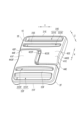
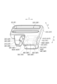
- FIG. 1 is a perspective view showing a connector according to a first embodiment of the present invention.
- FIG. 2 is a perspective view showing a connecting member of the connecting tool according to the first embodiment.
- FIG. 2 is an explanatory diagram showing a connecting member of the connecting tool according to the first embodiment.
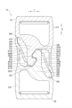
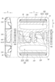
- FIG. 3 is a cross-sectional view showing a connected state of the connector according to the first embodiment.
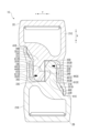
- FIG. 3 is a cross-sectional view showing the operation of the connector according to the first embodiment.
- FIG. 3 is a cross-sectional view showing a separated state of the connector according to the first embodiment.
- FIG. 7 is an external view showing the connector in a separated state shown in FIG. 6;
- FIG. 7 is a perspective view showing a connector according to a second embodiment of the present invention.
- FIG. 1 is a perspective view showing a connector according to a first embodiment of the present invention.
- FIG. 2 is a perspective view showing a connecting member of the connecting tool according to the first embodiment.
- FIG. 7 is a perspective view showing a connecting member of a connecting tool according to a second embodiment.
- FIG. 7 is an explanatory diagram showing a connecting member of a connecting tool according to a second embodiment.
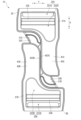
- FIG. 7 is a cross-sectional view showing a connected state of the connector according to the second embodiment.
- FIG. 7 is a cross-sectional view showing the operation of the connector according to the second embodiment.
- FIG. 7 is a cross-sectional view showing a separated state of the connector according to the second embodiment.
- FIG. 14 is an external view showing the connector in a separated state shown in FIG. 13;
- FIG. 7 is a perspective view showing a connector according to a third embodiment of the present invention.
- FIG. 7 is a perspective view showing a connecting member of a connecting tool according to a third embodiment.
- FIG. 7 is an explanatory diagram showing a connected state of a connecting tool according to a third embodiment.
- FIG. 7 is a rear view showing the connector according to the third embodiment from the back side.
- FIG. 7 is a cross-sectional view showing a connected state of a connector according to a fourth embodiment of the present invention.
- FIG. 7 is a perspective view showing a connector according to a fifth embodiment of the present invention.
- FIG. 7 is a perspective view showing a connecting member of a connecting tool according to a fifth embodiment.
- FIG. 7 is a rear view showing the connector according to the fifth embodiment from the back side.
- FIG. 7 is an explanatory diagram showing a connector according to a sixth embodiment of the present invention.
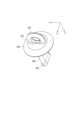
- FIG. 7 is a perspective view showing a regulating member of a connector according to a sixth embodiment.
- a buckle 1 as a connector includes connecting members 2A and 2B (a first connecting member and a second connecting member), which are separably connected to each other. It is something.
- the connecting member 2A has a base portion 21A (first base portion), a plug portion 31A (first plug portion) and a socket portion 41A (first socket portion) extending from the base portion 21A.
- the connecting member 2B (second connecting member) is configured in approximately the same manner as the connecting member 2A, and includes a base 21B (second base) and a plug portion 31B formed similarly to the base 21A, plug portion 31A, and socket portion 41A.
- the X direction is the insertion direction of the buckle 1
- the Y direction perpendicular to the X direction is the width direction (left and right direction) of the buckle 1
- the Z direction perpendicular to the X and Y directions is the thickness of the buckle 1. direction (front and back direction).
- the +X direction is the direction toward the insertion side of the connection member 2A into the connection member 2B
- the -X direction is the direction toward the insertion side of the connection member 2B into the connection member 2A
- the +Y direction is the direction in the width direction of the buckle 1.
- the -Y direction is the direction toward the other side in the width direction of the buckle 1
- the +Z direction is the direction toward the front side of the buckle 1
- the -Z direction is the direction toward the back side of the buckle 1.
- the connecting members 2A and 2B are formed into a flat shape. Although the connecting members 2A and 2B are made of synthetic resin, they may be made of other materials such as metal as long as the connecting members 2A and 2B can be connected and separated from each other.
- the plug portion 31A and the socket portion 41A extend from the base portion 21A in the X direction and are arranged in parallel with each other in the Y direction.
- the base 21A has a mounting hole 22A through which a belt (not shown) as a string-like body is passed, and a bar 23A extending in the Y direction in the mounting hole 22A and around which the belt is wound.
- the mounting hole 22A is divided into two holes 221A and 222A by a bar 23A.
- the base portion 21A formed in this manner is configured as a belt attachment portion to which a belt is attached.
- the plug portion 31A of the connecting member 2A is configured to be able to engage with the plug portion 31B of the connecting member 2B in the X direction, and has a leg portion 32A extending from the base portion 21A in the Y direction and a leg portion 32A formed at the tip of the plug portion 31A. It has a claw portion 33A.
- the claw portion 33A is arranged between the base portion 21B and the claw portion 33B of the connecting member 2B, and the claw portion 33B of the connecting member 2B is arranged between the base portion 21A and the claw portion 33A.
- Ru The claw portion 33A protrudes in the Y direction ( ⁇ Y direction in the connecting member 2A shown in FIG.
- the leg portion 32A is a portion of the plug portion 31A excluding the claw portion 33A, and its width in the Y direction gradually increases from the claw portion 33A side toward the base portion 21A side.
- the base end of the leg portion 32A has a thickness dimension equivalent to the dimension in the Z direction between inner surfaces 421A and 431A of the socket portion 41A, which will be described later.
- the portion of the leg portion 32A on the distal side from the base end has a thickness smaller than the thickness of the base end in the Z direction, and has the same thickness as the claw portion 33A.
- the portion of the leg portion 32A on the claw portion 33A side and the claw portion 33A have a width smaller than the width in the Y direction between the leaf spring 51A and the claw portion 33A, which will be described later.
- the width dimension is smaller than the width dimension in the Y direction between the leaf spring 51B and the claw portion 33B of the connecting member 2B configured similarly to the above.
- the portion of the leg portion 32A on the base portion 21A side has a width dimension larger than the width dimension in the Y direction between the leaf spring 51A and the claw portion 33A, and therefore is configured similarly to the connecting member 2A.
- the width dimension is larger than the width dimension in the Y direction between the leaf spring 51B and the claw portion 33B of the connecting member 2B.
- the surface of the plug portion 31A located on the opposite side from the socket portion 41A in the Y direction is configured as a guide surface 35A against which the tip of the leaf spring 51B comes into contact.
- the guide surface 35A is formed as a gently convex curved surface extending from the base end to the distal end of the plug portion 31A, and the end of the guide surface 35A on the claw portion 33A side is closer than the end on the base portion 21A side. is also inclined with respect to the X direction so as to be located on the socket portion 41A side.
- the socket part 41A is arranged on the -Y direction side with respect to the plug part 31A, and has a front wall part 42A and a back wall part 43A that are continuous to the base part 21A, and a side wall that is continuous to the front wall part 42A and the back wall part 43A. It has a section 44A.
- the socket portion 41A is continuously open in the +X direction and the +Y direction, and the tip of the socket portion 41A is located closer to the +X direction than the tip of the plug portion 31A.
- a continuous portion between the front wall portion 42A, the back wall portion 43A, and the base portion 21A is curved into a concave curved shape.
- the side edge portion 422A along the X direction located on the plug portion 31A side of the front wall portion 42A is arranged such that the outer portion thereof is located on the ⁇ Y direction side farther from the plug portion 31A side than the inner portion in the Z direction. It is curved and inclined with respect to the Z direction.
- the side edge portion 423A along the X direction located on the plug portion 31A side of the back wall portion 43A is arranged such that the outer portion thereof is located on the ⁇ Y direction side farther from the plug portion 31A side than the inner portion in the Z direction. It is curved and inclined with respect to the Z direction.
- the inner surfaces 421A and 431A have a width dimension in the Y direction that can accommodate the plug portion 31B.
- a recessed part 443A is formed on the outer surface 442A of the side wall part 44A so that the buckle 1 can be easily gripped.
- a plate spring 51A serving as a first biasing portion (biasing portion) is integrally formed in the interior 45A of the socket portion 41A described above.
- the leaf spring 51A is configured to bias the plug portion 31B, which is inserted into the socket portion 41A and brought into the inserted state, toward the plug portion 31A side, and in this embodiment, extends from the bottom surface 411A in the +X direction. It is formed by putting it out.
- the leaf spring 51A extends in the +X direction from the position of the engagement surface 34A of the plug portion 31A, and extends to a position facing the claw portion 33A in the Y direction. In the X direction, the tip of the leaf spring 51A is located at approximately the same position as the tip of the plug portion 31A.
- the leaf spring 51A is arranged at a distance in the Y direction from the side wall portion 44A, and is configured to be elastically deformable by this distance.
- a plate spring 51B serving as a second biasing portion (biasing portion) is formed in the interior 45B of the socket portion 41B of the connecting member 2B.
- the connecting members 2A and 2B are prepared, and the plug part 31A and the socket part 41B are arranged to face each other in the X direction, and the plug part 31B and the socket part 41A are arranged to face each other in the X direction.
- the connecting members 2A and 2B are brought closer to each other in the X direction, the connecting member 2A is moved in the +X direction with respect to the connecting member 2B, and the connecting member 2B is moved in the ⁇ X direction with respect to the connecting member 2A.
- the plug portion 31A of the connecting member 2A is inserted between the leaf spring 51B and the plug portion 31B of the connecting member 2B, and the plug portion 31B of the connecting member 2B is inserted between the leaf spring 51A and the plug portion 31A of the connecting member 2A. Insert it into the
- the leaf spring 51A is elastically deformed in the +Y direction
- the leaf spring 51B is elastically deformed in the ⁇ Y direction
- the plug of the connecting member 2A is
- the portion 31A is arranged between the claw portion 33B and the base 21B of the connecting member 2B
- the plug portion 31B of the connecting member 2B is arranged between the claw portion 33A and the base 21A of the connecting member 2A
- the leaf springs 51A, 51B is restored to its original state, resulting in an engaged state in which the engaging surfaces 34A and 34B overlap each other.
- the plug portions 31A and 31B collide with each other in the Y direction due to the restoring force of the leaf springs 51A and 51B, creating a click feeling when the plugs are engaged.
- the claw portion 33A is in contact with the leg portion 32B
- the claw portion 33B is in contact with the leg portion 32A
- the tip of the leaf spring 51A is in contact with the guide surface 35B
- the tip of the leaf spring 51B is in contact with the guide surface 35B. comes into contact with the guide surface 35A.
- the engaged state as shown in FIG.
- the side edges 422A, 423A of the socket portion 41A and the side edges 422B, 423B of the socket portion 41B are spaced apart from each other in the Y direction,
- the tip of the socket portion 41A on the +X direction side is in contact with the base portion 21B, and the tip of the socket portion 41B on the ⁇ X direction side is in contact with the base portion 21A.
- the inner surface 441A of the socket portion 41A is spaced apart from the plug portion 31B in the Y direction, and the leaf spring 51A is arranged between the inner surface 441A and the plug portion 31B.
- the inner surface 441B of the socket portion 41B is arranged at a distance in the Y direction from the plug portion 31A, and the leaf spring 51B is arranged between the inner surface 441B and the plug portion 31A. In this way, the buckle 1 enters an engaged state when the connecting members 2A, 2B move apart from each other in the Y direction, thereby connecting the connecting members 2A, 2B to each other.
- the engagement surfaces 34A and 34B are disposed at positions separated from each other in the Y direction to create a disengaged state in which the claw portions 33A and 33B are disengaged.
- the plate spring 51A is elastically deformed in the +Y direction and pressed against the guide surface 35B, and the plate spring 51B is elastically deformed in the -Y direction and pressed against the guide surface 35A.
- the connecting member 2A is moved in the -X direction.
- the connecting member 2B moves in the +X direction, and the connecting members 2A and 2B are brought into a separated state as shown in FIG.
- the side edges 422A, 423A of the socket part 41A and the side edges 422B, 423B of the socket part 41B approach each other as shown in FIG.
- a buckle 1C as a coupling device includes coupling members 2C and 2D (a first coupling member and a second coupling member), which are separably coupled to each other. It is something.
- the connecting member 2C has a base 21C (first base), a plug portion 31C (first plug portion) and a socket portion 41C (first socket portion) extending from the base portion 21C.
- the connecting member 2D (second connecting member) is configured in approximately the same manner as the connecting member 2C, and includes a base 21D (second base) and a plug portion 31D formed in the same manner as the base 21C, plug portion 31C, and socket portion 41C. (second plug part) and a socket part 41D (second socket part).
- base 21D second base
- plug portion 31D formed in the same manner as the base 21C, plug portion 31C, and socket portion 41C.
- socket part 41D second socket part
- the base portion 21C, plug portion 31C, and socket portion 41C of the connecting member 2C are configured in approximately the same manner as the base portion 21A, plug portion 31A, and socket portion 41A of the connecting member 2A in the first embodiment, but the guide of the plug portion 31C is The configuration of the surface 35C and the configuration in which a plate spring 61C as a first biasing section (biasing section) extends from the inner surface 441C of the socket portion 41A instead of the bottom surface 411A differ from the connecting member 2A.
- a plate spring 61D as a second biasing portion (biasing portion) is formed to extend from the connecting member 2D.
- the guide surface 35C is disposed on the surface of the plug portion 31C opposite to the socket portion 41C in the Y direction, and includes an inclined surface 351C provided on the base end side of the plug portion 31C as shown in FIG. It has a convex curved surface 352C provided at the tip of the plug portion 31C, and a surface between the inclined surface 351C and the convex curved surface 352C of the plug portion 31C is constituted by a face 353C along the X direction.
- the inclined surface 351C is inclined with respect to the X direction so that the end on the convex curved surface 352C side is located closer to the socket part 41C than the end on the base 21C side.
- the portion 33C is curved in a convex shape toward the tip in the X direction.
- the guide surface 35C has an inclined surface 351C in contact with the tip of the side wall portion 44D in the ⁇ X direction, and a convex curved surface 352C in the disengaged state shown in FIG.
- the connecting member 2C is guided away from the connecting member 2D in the -X direction while being urged in the -Y direction by 611D. Note that when the connecting member 2C separates from the connecting member 2D in the ⁇ X direction, the inclined surface 351C and the tip of the side wall portion 44C separate in the X direction as shown in FIG.
- the claw portion 33C protrudes in the Y direction ( ⁇ Y direction in the connecting member 2C shown in FIG. 11) from a continuous portion with the leg portion 32C toward the socket portion 41C, and the claw portion 33D protrudes from the continuous portion with the leg portion 32C. It protrudes in the Y direction (+Y direction in the connecting member 2D shown in FIG. 11) from the continuous portion with the socket portion 41D.
- the leaf spring 61C extends from the inner surface 441C of the side wall 44C toward the base 21C, and is inclined with respect to the X direction so that its tip 611C is spaced apart from the inner surface 441C.
- the tip 611C of the leaf spring 61C is disposed at a position corresponding to the position in the X direction where the claw portion 33D of the plug portion 31D in the engaged state is disposed, and is located closer to the proximal end 612C than the tip 611C. It protrudes in the +Y direction toward the plug portion 31C side.
- a recessed portion 444C is formed in a portion of the side wall portion 44C that is continuous with the leaf spring 61C.
- the procedure for connecting and separating the connecting members 2C and 2D of the buckle 1C described above is roughly the same as that of the buckle 1 according to the first embodiment, but the guidance by the guide surfaces 35C and 35D and the elastic deformation of the leaf springs 61C and 61D are Different from buckle 1.
- the guidance by the guide surface 35C is as described above, and the guidance by the guide surface 35D similarly guides the connecting member 2D away from the connecting member 2C in the +X direction.
- the leaf spring 61C is pushed in the -Y direction by the plug part 31D when connecting the connecting members 2C and 2D, and is elastically deformed in the -Y direction, so that the plug parts 31C and 31D are in an engaged state as shown in FIG.
- the tip 611C is in contact with the plug portion 31C, it returns to its original state and maintains the engaged state.
- the plate spring 61D is pushed in the +Y direction by the plug portion 31C when connecting the connecting members 2C and 2D, and is elastically deformed in the +Y direction, so that the plug portions 31C and 31D are in an engaged state as shown in FIG.
- the distal end 611D is in contact with the plug portion 31C, the distal end 611D returns to its original state and maintains the engaged state.
- the plate spring 61C is pushed by the plug portion 31D and elastically deforms in the ⁇ Y direction when the plug portions 31C and 31D are brought into a disengaged state in which the engagement is released as shown in FIG.
- the tip of the side wall portion 44C comes into contact with the inclined surface 351D of the connecting member 2D, and the tip 611C of the leaf spring 61C is pressed against the convex curved surface 352D. Therefore, the convex curved surface 352D that receives the restoring force of the leaf spring 61C guides the connecting member 2C away from the connecting member 2D in the -X direction.
- the plate spring 61D is pushed by the plug portion 31C and elastically deforms in the +Y direction.
- the tip of the side wall portion 44D comes into contact with the inclined surface 351C of the connecting member 2C, and the tip 611D of the leaf spring 61D is pressed against the convex curved surface 352C. Therefore, the convex curved surface 352D that receives the restoring force of the leaf spring 61D guides the connecting member 2D away from the connecting member 2C in the +X direction.
- the connecting members 2C and 2D guided apart in this manner are in a separated state in which they are separated from each other in the X direction, as shown in FIG. The appearance of the separated state is as shown in FIG.
- the side edges 422C, 423C and the side edges 422D, 423D of the socket parts 41C, 41D approach each other in the Y direction; Since it is formed to be inclined like the side edges 422D and 423D, it is possible to prevent fingers from being pinched between the side edges 422C and 422C or between the side edges 423D and 423D.
- a buckle 1E as a connector includes connecting members 2E, 2F (a first connecting member, a second connecting member), which are separably connected to each other. It is something.
- the connecting member 2E has a base 21E (first base), a plug portion 31E (first plug portion) and a socket portion 41E (first socket portion) extending from the base portion 21E.
- the connecting member 2F (second connecting member) is configured in approximately the same manner as the connecting member 2E, and includes a base 21F (second base) and a plug portion 31F formed similarly to the base 21E, plug portion 31E, and socket portion 41E.
- the base portion 21E, the plug portion 31E, and the socket portion 41E of the connecting member 2E are configured approximately the same as the base portion 21A, the plug portion 31A, and the socket portion 41A of the connecting member 2A in the first embodiment, but the socket portion 41E is , has an engaging portion 71E (first engaging portion) that engages with the plug portion 31F in the engaged state, and the socket portion 41F has an engaging portion 71F (first engaging portion) that engages with the plug portion 31E in the engaged state. It differs from the connecting member 2A in that it has a second engaging portion).
- the engaging portion 71E extends in the X direction from the bottom surface 411E of the socket portion 41E, and has a claw portion 72E at its tip that projects in the Y direction toward the leaf spring 51E side. have.
- the engaging part 71E is disposed inside the socket part 41E at a position along the side edges 422E and 423E of the front wall part 42E and the back wall part 43E, and is attached to the front wall part 42E and the back wall part 43E. It is continuous as one.
- the engaging portion 71E is arranged at a distance from the leaf spring 51E on the inside in the Y direction (on the plug portion 31E side).
- the engaging portion 71F extends in the X direction from the bottom surface 411F of the socket portion 41F, and has a claw portion 72F that protrudes in the Y direction toward the leaf spring 51F at its tip.
- the engaging part 71F is disposed inside the socket part 41F at a position along the side edges 422F and 423F of the front wall part 42F and the back wall part 43F, and is located inside the socket part 41F at a position along the side edges 422F and 423F of the front wall part 42F and the back wall part 43F. are continuous. Furthermore, the engaging portion 71F is arranged at a distance from the leaf spring 51F on the inside in the Y direction (on the plug portion 31F side).
- the claw portion 33E of the plug portion 31E protrudes in the Y direction ( ⁇ Y direction in the case of the connecting member 2E) from a continuous portion with the leg portion 32E toward the socket portion 41E
- the claw portion 33F of the plug portion 31E protrudes in the Y direction (+Y direction in the case of the connecting member 2F) from a continuous portion with the leg portion 32F toward the socket portion 41F side.
- the plug part 31F is inserted between the leaf spring 51E and the engaging part 71E, and the plug part 31E is inserted between the leaf spring 51F and the engaging part 71F, so that the claw of the plug part 31F
- the portion 33F engages with the claw portion 72E of the engaging portion 71E, and the claw portion 33E of the plug portion 31E engages with the claw portion 72F of the engaging portion 71F, resulting in the engaged state shown in FIGS. 18 and 19, and the connection is completed.
- the members 2E and 2F are in a connected state.
- the engaging parts 71E, 71F are arranged between the plug parts 31E, 31F in the Y direction, and the engaging parts 71E, 71F are arranged at intervals in the Y direction. This interval corresponds to the amount of elastic deformation of the leaf springs 51E, 51F when the engagement state is released.
- the buckle 1E is grasped to move the connecting members 2E, 2F closer to each other in the Y direction.
- the plate spring 51E is elastically deformed, and the engagement between the claw part 33F of the plug part 31F and the claw part 72E of the engaging part 71E is released, and the plug part 31F can be pulled out from the socket part 41E.
- the leaf spring 51F is elastically deformed, and the engagement between the claw portion 33E of the plug portion 31E and the claw portion 72F of the engaging portion 71F is released, and the plug portion 31E can be pulled out from the socket portion 41F. It becomes a state.
- the elastically deformed leaf springs 51E, 51F elastically urge the guide surfaces 35E, 35F of the plug portions 31E, 31F, so that the connecting members 2E, 2F are separated in the X direction and are in a separated state.
- the connecting members 2E and 2F are engaged at two locations spaced apart in the Y direction, which is better than the case where they are engaged at one location as in the first and second embodiments, for example. It is also possible to increase the engagement strength, and for example, it is possible to create a connected state in which torsional deformation around the virtual axis along the X direction is less likely to occur. Furthermore, since the engaging portions 71E and 71F are not exposed to the outside, the design can be improved.
- FIG. 20 A fourth embodiment of the present invention will be described below based on the drawings.
- a buckle 1G as a connector according to the fourth embodiment is configured in the same manner as the buckle 1E according to the third embodiment, but instead of leaf springs 51E and 51F as biasing parts, It has leaf springs 61G and 61H as force parts.
- each component similar to that of the buckle 1E is given the same reference numeral.
- the leaf springs 61G and 61H are configured similarly to each other, and are formed in the same manner as the leaf springs 61C and 61D described above.
- “G, H” are added instead of "C, D" in the reference numerals given to each structure of the leaf springs 61C, 61D, and detailed explanation will be omitted.
- the leaf spring 61G is inclined with respect to the X direction so that the tip 611G side thereof is further away from the inner surface 441E than the base end 612G, and the claw portion 33F of the plug portion 31F in the engaged state is arranged at the tip 611G. It is arranged at a position corresponding to the position in the X direction, and protrudes toward the plug portion 31E side in the Y direction.
- the leaf spring 61H is inclined with respect to the X direction so that the distal end 611H side thereof is further away from the inner surface 441F than the base end 612H, and the distal end 611H is such that the claw portion 33E of the plug portion 31E in the engaged state It is arranged at a position corresponding to the position in the X direction, and protrudes toward the plug portion 31F side in the Y direction.
- a buckle 1J as a connector according to the fifth embodiment is configured in the same manner as the buckle 1E according to the third embodiment, but between the engaging part 71E and the base part 21E.
- the structure differs from that of the buckle 1E in that an opening 73J is formed, and an opening 73K is formed between the engaging portion 71F and the base 21F.
- components of the buckle 1J that are similar to those of the buckle 1E are given the same reference numerals as appropriate, and detailed description thereof will be omitted.
- the opening 73J is defined by the engaging portion 71E and the base 21E, and the front wall portion 42E and the back wall portion 43E.
- the claw portion 33F (the tip of the plug portion 31F) is arranged in the mated state.
- the opening 73K is divided by the engaging part 71F and the base part 21F, and the front wall part 42F and the back wall part 43F, and the claw part 33E of the plug part 31E is engaged with the claw part 72E of the engaging part 71F.
- the claw portion 33E (the tip of the plug portion 31E) is arranged in the engaged state. Therefore, since the claw portions 33E and 33F can be arranged in the openings 73J and 73K, the width of the buckle 1J can be reduced by reducing the distance 75 shown in FIG. 23 in the Y direction.
- FIG. 24 A sixth embodiment of the present invention will be described below based on the drawings.
- a buckle 1L as a connector according to the sixth embodiment is configured in the same manner as the buckle 1E according to the third embodiment, but there is a restriction that restricts mutual approaching movement of the connecting members in the Y direction.
- the configuration in which the member 81L is removably provided differs from the configuration of the buckle 1E. It should be noted that components of the buckle 1L that are similar to those of the buckle 1E are given the same reference numerals as appropriate, and detailed description thereof will be omitted.
- the regulating member 81L includes a knob 82L that is inserted and removed, a substantially disc-shaped base 83L that is continuous with the knob 82L, and a base that extends in the Z direction from the base 83L. It has a protruding insertion piece 84L and an end 85L that bulges out at the -Z direction side tip of the insertion piece 87L.
- the knob part 82L is arranged on the +Z direction side with respect to the base part 83L, and the insertion piece part 84 is formed in a flat plate shape, and is arranged on the +Z direction side with respect to the base part 83L. .
- the length dimension of the insertion piece part 84 in the Z direction corresponds to the thickness dimension in the Z direction of the socket parts 41E and 41F, and the end part 85 protrudes when inserted between the socket parts 41E and 41F.
- the length dimension is the length of the
- the end portion 85L has a substantially circular cross section when viewed from the X direction, and is formed to be larger than the thickness of the insertion piece portion 84L in the Y direction.
- the insertion piece part 84L is arranged to restrict the mutual approach movement of the socket parts 41E and 41F in the Y direction. Therefore, even if an attempt is made to operate the buckle 1L, the above-mentioned approach movement is restricted and the connected state between the connecting members 2E and 2F is maintained.
- the socket parts 41E and 41F of the buckle 1L are moved in the Y direction. They become able to move closer to each other. Therefore, the connecting members 2E and 2F of the buckle 1L can be separated.
- the buckles 1, 1C, 1E, 1G, 1J, and 1L are described as connectors; It may also be configured as a connector that connects two objects.
- it may be formed into a ring shape with an openable/closable opening/closing member attached thereto, and may be formed into a shape on which other items can be hooked.
- the connecting members 2A and 2B are similarly formed members, the connecting members 2C and 2D are similarly formed members, and the connecting members 2E and 2F are similarly formed members.
- the configuration is not limited to this, and the shapes may be slightly different as long as the members can be connected and separated from each other.
- only one of the connecting members 2A and 2B, only one of the connecting members 2C and 2D, or only one of the connecting members 2E and 2F is attached with a leaf spring or the like.
- a force section may be provided.
- guide surfaces 35A and 35B are formed in the plug parts 31A and 31B
- guide surfaces 35C and 35D are formed in the plug parts 31C and 31D
- guide surfaces 35E and 35F are formed in the plug parts 31E and 31F.
- a guide surface is formed only on one of the plug parts 31A and 31B, only on one of the plug parts 31C and 31D, and only on one of the plug parts 31E and 31F. You can leave it there.
- connection members 2A and 2B may be separated from each other, the connection members 2C and 2D from each other, and the connection members 2E and 2F from each other without being guided by the guide surfaces 35A to 35F
- the configuration of the guide surfaces 35A to 35F may be changed. May be omitted.
- the side edges 422A to 422F, 423A to 423F of the socket parts 41A to 41F are inclined as described above to suppress finger pinching, but finger pinching may occur. If the configuration is difficult, the side edges 422A to 422F, 423A to 423F may be formed along the Z direction without being inclined.
- the plate springs 51A, 51B, 51E, 51F, 61C, 61D, 61G, and 61H are described as biasing parts, but any configuration that can bias the plug parts 31A to 31F in the Y direction may be used.
- an elastic body having another shape may be used as the biasing portion.
- the dimension of the claw portion 33B of the plug portion 31B in the Y direction is smaller than the dimension of the leaf spring 51A and the plug portion 31A in the Y direction, and the leg portion 32B of the plug portion 31B (claw portion
- the dimension in the Y direction of the part (excluding the part) gradually increases from the claw part 33B toward the base part 21B and is made larger than the dimension in the Y direction of the leaf spring 51A and the plug part 31A, but is not limited to this. .
- the dimension in the Y direction of the claw portion 33B of the plug portion 31B is equal to or greater than the dimension in the Y direction of the leaf spring 51A and the plug portion 31A.
- the dimension in the Y direction of the leg part 32B of the plug part 31B does not need to gradually increase from the claw part 33B toward the base part 21B, and the dimension in the Y direction of the plate spring 51A and the plug part 31A
- the dimensions may be equal to or smaller than the dimensions in .
- the plate springs 51A, 51E move the bottom surface 411A, 51E to a position facing the claw portions 33B, 33F of the plug portions 31B, 31F in the Y direction in the engaged state.
- the length dimension extends from 411E, the length dimension is not limited to this, as long as the connecting members 2A, 2E and the connecting members 2B, 2F can be connected and separated from each other, for example, the plate springs 51A, 51E does not extend to a position facing the claw parts 33B, 33F of the plug parts 31B, 31F in the Y direction in the engaged state, but extends from the bottom surfaces 411A, 411E to a position in front of the facing position. It may be a configuration.
- the plate springs 51B, 51F extend from the bottom surfaces 411B, 411F to positions facing the claw portions 33A, 33E of the plug portions 31A, 31E in the Y direction in the engaged state, but the invention is not limited thereto. It is only necessary that the connecting members 2A, 2E and the connecting members 2B, 2F can be connected and separated from each other.
- the leaf spring 51B is in the Y direction with respect to the claw parts 33A, 33E of the plug parts 31A, 31E in the engaged state. It may be configured such that it does not extend to a position facing the opposite position, but extends from the bottom surfaces 411B, 411F to a position in front of the facing position.
- the leaf springs 61C, 61G extend from the inner surfaces 441C, 441E of the side walls 44C, 44E toward the bases 21C, 21E, but the invention is not limited thereto.
- 2E and the connecting members 2D, 2F can be connected and separated from each other.
- the leaf springs 61C, 61G have inner surfaces 441C, 441E facing away from the bases 21C, 21E in the +X direction. It may extend from.
- the leaf springs 61D, 61F extend from the inner surfaces 441D, 441F of the side walls 44D, 44F toward the bases 21D, 21F, but are not limited to this, and the connecting members 2C, 2E, the connecting member 2D,
- the leaf springs 61D, 61E may extend from the inner surfaces 441D, 441E toward the side away from the bases 21D, 21F in the ⁇ X direction.
- the tips 611C and 611G of the leaf springs 61C and 61G are arranged at positions corresponding to the positions in the X direction where the claw parts 33D and 33F of the plug parts 31D and 31F in the engaged state are arranged.
- the present invention is not limited to this, and any structure may be used as long as the connecting members 2C, 2E and the connecting members 2D, 2F can be connected to and separated from each other.
- the tip end 611C, 611G may be arranged at a position in front of the claw parts 33D, 33F without extending to a position corresponding to the position in the X direction where the claw parts 33D, 33F of 31F are arranged.
- the tips 611D and 611H of the leaf springs 61D and 61H are arranged at positions corresponding to the positions in the X direction where the claw parts 33C and 33E of the plug parts 31C and 31E in the engaged state are arranged, but the present invention is not limited thereto.
- the connecting members 2C, 2E and the connecting members 2D, 2F can be connected and separated from each other, for example, the claws 33C, 33E of the plug parts 31C, 31E in which the leaf springs 61D, 61H are engaged
- the tip ends 611D, 611H may be arranged in front of the claws 33C, 33E without extending to a position corresponding to the position in the X direction where they are arranged.
- the tips 611C, 611G of the leaf springs 61C, 61G are +Y toward the plug portions 31C, 31E with respect to the portions closer to the base ends 612C, 612H than the tips 611C, 611G.
- the present invention is not limited to this, and as long as the connecting members 2C, 2E and the connecting members 2D, 2F can be connected and separated from each other, the distal ends 611C, 611G are closer to the proximal ends 612C, 612H than the connecting members 2C, 2E and the connecting members 2D, 2F. It does not need to protrude in the +Y direction with respect to the portion.
- the tips 611D, 611H of the leaf springs 61D, 61G protrude in the ⁇ Y direction toward the plug portions 31D, 31F with respect to the portions closer to the proximal ends 612D, 612H than the tips 611D, 611H.
- the present invention is not limited to this, but if the connecting members 2C, 2E and the connecting members 2D, 2F are configured to be able to be connected and separated from each other, the distal ends 611D, 611H are - It does not need to protrude in the Y direction.
- the buckles 1, 1C, 1E, 1G, 1J, 1L of the first to sixth embodiments are connectors that connect the connecting members 2A, 2C, 2E and the connecting members 2B, 2D, 2F in a separable manner.
- the members 2A, 2C, 2E have base parts 21A, 21C, 21E, plug parts 31A, 31C, 31E and socket parts 41A, 41C, 41E extending from the base parts 21A, 21C, 21E, and the connecting members 2B, 2D, 2F have base parts 21B, 21D, 21F, plug parts 31B, 31D, 31F and socket parts 41B, 41D, 41F extending from the base parts 21B, 21D, 21F, and plug parts 31A, 31C, 31E.
- buckles 1, 1C, 1E, 1G, 1J, 1L are formed inside 45A, 45C, 45E of the socket parts 41A, 41C, 41E, and plug the plug parts 31A, 31C, 31E in the inserted state in the Y direction.
- Plate springs 51A, 51E, 61C, 61G as first biasing portions biasing toward the portions 31B, 31D, 31F, and insides 45A, 45D, 45F of the socket portions 41B, 41D, 41F are formed. At least one of the leaf springs 51B, 51F, 61D, and 61H as a second biasing portion that biases the plug portions 31B, 31D, and 31F in the inserted state toward the plug portions 31A, 31C, and 31E in the Y direction. It has plate springs 51A, 51E, 61C (or 51B, 51F, 61D) as biasing parts.
- the connecting members 2A, 2C, 2E and the connecting members 2B, 2D, 2F enter into an engaged state when they move away from each other in the Y direction, and when they move toward each other in the Y direction, the leaf spring serving as one of the urging members 51A, 51E, 61C (or 51B, 51F, 61D) to be in the disengaged state.
- the one biasing portion in connection and separation of the connection members 2A, 2C, and 2E, and the connection members 2B, 2D, and 2F, the one biasing portion
- the configuration can be such that one of the biasing parts is not exposed to the outside.
- the connecting members 2A, 2C, 2E and the connecting members 2B, 2D, 2F are in an engaged state when they are moved apart from each other in the Y direction.
- the engagement is released against the urging force of the leaf springs 51A, 51E, 61C (or 51B, 51F, 61D) as the one urging member. be done.
- the connecting members 2A, 2C, 2E and the connecting members 2B, 2D, 2E are connected, while the socket parts 41A, 41C, 41E and the socket parts 41B, 41D, 41E are connected to each other by Y.
- the coupling members 2A, 2C, 2E and the coupling members 2B, 2D, 2F closer to each other in the X direction, the engaged state can be released against the biasing force of one of the biasing parts. It can be made into a separable state.
- the plug portions 31A, 31C, and 31E have claw portions that protrude toward the socket portions 41A, 41C, and 41E in the Y direction. It has 33A, 33C, and 33E. According to such a configuration, since the protruding claw portions 33A, 33C, and 33E are provided as described above, the connecting members 2A, 2C, and 2E and the connecting members 2B, 2D, and 2F can be moved relative to each other in the Y direction.
- the claws 33A, 33C, 33E can be used to connect and separate the connecting members 2A, 2C, 2E and the connecting members 2B, 2D, 2F.
- the buckles 1, 1C, 1E, 1G, 1J, 1L of the first to sixth embodiments have both leaf springs 51A, 51E, 61C, 61G and leaf springs 51B, 51F, 61D, 61H, and the leaf spring 51A , 51E, 61C, 61G are in contact with the plug portions 31B, 31D, 31E when the connecting members 2A, 2C, 2E and the connecting members 2B, 2D, 2F are engaged, and the leaf springs 51B, 51F, Tips 611D, 611H of 61D, 61H abut against plug portions 31A, 31C, 31E in the engaged state.
- the plug parts 31A, 31C, 31E and the plug parts 31B, 31D, 31F in the engaged state are connected to the leaf springs 51A, 51E, 61C, 61G and the leaf springs 51B, 51F, 61D,
- the leaf springs 51A, 51E, 61C, 61G and The plug portions 31A to 31F in the engaged state can be held in the width direction by the leaf springs 51B, 51F, and 61D61H, thereby further improving the connected state of the connecting members 2A, 2C, and 2E and the connecting members 2B, 2D, and 2F. It can be stabilized.
- the plug portions 31A, 31C, and 31E are provided with connection members 2A, 2C, and 2E, and connection members 2B, 2D, and 2F.
- Guide surfaces 35A, 35C, 35E may be formed to separate the connecting members 2A, 2C, 2E and the connecting members 2B, 2D, 2F from each other in the X direction in the uncoupled state. According to such a configuration, the engagement of the plug parts 31A, 31C, 31E and the plug parts 31B, 31D, 31F is released by bringing the socket parts 41A, 41C, 41E and the socket parts 41B, 41D, 41F closer together in the Y direction.
- the connecting members 2A, 2C, 2E and the connecting members 2B, 2D, 2F can be separated from each other by the guide surfaces 35A, 35C, 35E, so that the operator can separate the socket parts 41A, 41C, 41E and the socket.
- the connecting members 2A, 2C, 2E and the connecting members 2B, 2D, 2F can be smoothly connected. Can be separated.
- the socket parts 41A, 41C, 41E and the socket parts 41B, 41D, 41F are connected to the connecting members 2A, 2C, 2E and the connecting member 2B. . , is inclined with respect to the Z direction so that the outer portion is located on the outer side in the Y direction than the inner portion in the Z direction. According to such a configuration, when the socket parts 41A, 41C, 41E and the socket parts 41B, 41D, 41F are brought close to each other, it is possible to prevent fingers from getting caught between the side edges 422A to 422F and 423A to 423F. This can reduce the risk of
- the plug parts 31A, 31C and the plug parts 31B, 31D are releasably engaged with each other. be done. According to such a configuration, compared to the case where the connecting members 2 to 2D are provided with engaging portions that engage with the plug portions 31A, 31C and the plug portions 31B, 31D, respectively, no separate engaging portion is provided. By reducing the widthwise dimensions of the buckles 1 and 1C, the connector can be made smaller.
- the socket portions 41A, 41E have the bottom surfaces 411A, 411E that partition the interiors 45A, 45E facing the base portions 21A, 21E.
- the biasing portions 51A, 51E are formed by leaf springs 51A, 51E extending in the X direction from the bottom surfaces 411A, 411E. According to such a configuration, since the one biasing portion 51A, 51E is formed by the aforementioned plate springs 51A, 51E, it is easy to cut out the mold when manufacturing the connecting members 2A, 2E and the connecting members 2B, 2E. Moreover, it is possible to eliminate the need to form die-cut holes or the like in the socket parts 41A, 41B, 41E, and 41F, for example, only for forming the biasing part.
- At least the socket portions 41A, 41E have inner surfaces 441A, 441E (side surfaces) that are continuous with the bottom surfaces 411A, 411E.
- the inner surfaces 441A, 441E are arranged at intervals in the Y direction from the plug parts 31B, 31F that are inserted into the socket parts 41A, 41E, and the leaf springs 51A, 51E as one of the biasing parts,
- the connecting members 2A, 2E and the connecting members 2B, 2F are engaged, they are arranged so as to be elastically deformable between the inner surfaces 441A, 441E and the plug parts 31B, 31F, and their tips abut against the plug parts 31B, 31F.
- the plug portions 31A, 31E and the plug portions 31B, 31F have claw portions 33A, 33B, 33E, 33F at their tips.
- the plate springs 51A, 51E as one of the biasing parts extend from the bottom surfaces 411A, 411E to positions facing the claw parts 33A, 33E of the plug parts 31A, 31E in the Y direction.
- the plug portion 31A and the plug portion 31B have claw portions 33A and 33B at their tips, and the dimension in the Y direction of the claw portion 33B of the plug portion 31B is the same as that of the leaf spring 51A and the plug portion 31A.
- the dimension in the Y direction of the leg portion 32B which is the portion of the plug portion 31B excluding the claw portion 33B, gradually increases from the claw portion 33B toward the base 21B, and and the size of the plug portion 31A in the Y direction.
- the plug portion 31B can be easily inserted between the leaf spring 51A and the plug portion 31A;
- the plug portion 31B can be pressed by the leaf spring 51A, and a good engagement state can be achieved. can.
- the plug portion 31B and the plug portion 31A are engaged from the state in which the plug portion 31B is pressed by the leaf spring 51A, a click feeling can be produced when these engage.
- the socket portions 41C and 41E have inner surfaces 441C and 441E that partition their interiors 45C and 45E, and the one biasing portion 61C and 61G has It is formed by leaf springs 61C, 61G extending from the inner surfaces 441C, 441E.
- the socket parts 41C, 41E have bottom surfaces 411C, 411E that partition the insides 45C, 45E, and a biasing part such as a leaf spring is formed on the bottom surfaces 411C, 411E. Therefore, even if the space for forming the biasing portion is small, it is easy to form the plate springs 61C, 61G, and therefore the buckles 1C, 1G can be made smaller.
- the leaf springs 61C and 61G as one of the biasing portions extend from the inner surfaces 441C and 441E toward the bases 21C and 21E.
- the leaf springs 61C, 61G of the socket parts 41C, 41E can also be used as guides for guiding the plug parts 31D, 31F between the leaf springs 61C, 61G and the plug parts 31C, 31E. , Therefore, the connecting members 2C, 2E and the connecting members 2D, 2F can be smoothly connected.
- the leaf springs 61C and 61G as one of the biasing parts are arranged such that their tips 611C and 611G are spaced apart from the inner surfaces 441C and 441E in the X direction. tilt. According to such a configuration, an interval corresponding to the elastic deformation of the leaf springs 61C, 61G can be easily formed between the tips 611C, 611G of the leaf springs 61C, 61G and the inner surfaces 441C, 441E.
- the plug portions 31C and 31E and the plug portions 31D and 31F have claw portions 33C, 33D, 33E and 33F at their tips, and a plate spring serves as one of the biasing portions. Tips 611C and 611G of 61C and 61G are arranged at positions corresponding to the positions in the X direction where the claw parts 33D and 33F of the plug parts 31D and 31F in the engaged state are arranged. According to such a configuration, the claw portions 33D, 33F of the plug portions 31D, 31F can be pressed by the tips 611C, 611G of the leaf springs 61C, 61G, thereby stabilizing the engaged state of the plug portions 31D, 31F. I can do it.
- the tips 611C and 611G of the leaf springs 61C and 61G which serve as the one biasing portion, protrude toward the plug portions 31C and 31E in the Y direction. According to such a configuration, after the plug portions 31D, 31F abut against the tips 611C, 611G of the leaf springs 61C, 61G, the elastic deformation of the leaf springs 61C, 61G increases, and the engagement of the plug portions 31D, 31F increases. It is possible to stabilize the matching state.
- the elastic deformation of the leaf springs 61C and 61G can be kept small until the plug parts 31D, 31F come into contact with the tips 611C, 611G of the leaf springs 61C, 61G. Can be inserted.
- the socket portion 41E has an engaging portion 71E that engages with the plug portion 31F when the connecting member 2E and the connecting member 2F are engaged
- the socket part 41F has an engaging part 71F that engages with the plug part 31E in the engaged state
- the engaging parts 71E and 71F are spaced apart from each other in the engaged state between the plug parts 31E and 31F in the Y direction. are placed apart from each other.
- the engaging part 71E is arranged inside the socket part 41E 45E, and the engaging part 71F is arranged inside the socket part 41F 45F.
- the engaging portion 71E and the engaging portion 71F can be configured not to be exposed to the outside, and the design can be improved.
- an opening 73J is formed between the engaging portion 71E and the base 21E, in which the tip of the plug portion 31F is disposed in the engaged state, and the opening 73J is formed between the engaging portion 71E and the base 21E.
- An opening 73K is formed therebetween, in which the tip of the plug portion 31E is disposed in an engaged state.
- a regulating member 81L is removably provided between the engaging portions 71E and 71F, which regulates mutual approaching movement in the Y direction of the connecting members 2E and 2F in the engaged state.
- the connecting members 2E and 2F are prevented from moving toward each other in the Y direction, thereby preventing the aforementioned engagement from being released. Thereby, the engaged state can be maintained more reliably. Further, by removing the regulating member 81L from between the engaging portions 71E and 71F, the connecting members 2E and 2F are allowed to move toward each other, and the disengaged state can be made possible.
- connection Matching surface 351C, 351D... Inclined surface, 352C, 352D... Convex curved surface, 353C, 353D... Face, 35A to 35F... Guide surface, 411A to 411F... Bottom surface, 41A, 41C, 41E... Socket part (first socket part) , 41B, 41D, 41F... socket part (second socket part), 421A to 421F, 431A to 431F... inner surface, 422A to 422F, 423A to 423F... side edge part, 42A to 42F... surface wall part, 43A to 43F...
- Back wall part 441A to 441F...inner surface (side surface), 442A to 442F...outer surface, 443A to 443F...recessed part, 44A to 44F...side wall part, 444C, 444D, 444G, 444H...recessed part, 45A to 45F...interior , 46, 75... Spacing, 51A, 51E, 61C, 61G... Leaf spring (first biasing part), 51B, 51F, 61D, 61H... Leaf spring (second biasing part), 611C, 611D, 611G, 611H ... Tip, 612C, 612D, 612G, 612H... Base end, 71E... Engaging part (first engaging part), 71F... Engaging part (second engaging part), 73J, 73K... Opening, 81L... Regulating member , 82L...knob part, 83L...base part, 84L...insertion piece part, 85L...end part.
Landscapes
- Buckles (AREA)
- Details Of Connecting Devices For Male And Female Coupling (AREA)
Priority Applications (4)
| Application Number | Priority Date | Filing Date | Title |
|---|---|---|---|
| JP2024524085A JP7727847B2 (ja) | 2022-06-01 | 2022-06-01 | 連結具 |
| DE112022007330.6T DE112022007330T5 (de) | 2022-06-01 | 2022-06-01 | Befestigungseinrichtung |
| CN202280096428.3A CN119255723A (zh) | 2022-06-01 | 2022-06-01 | 连结器具 |
| PCT/JP2022/022384 WO2023233598A1 (ja) | 2022-06-01 | 2022-06-01 | 連結具 |
Applications Claiming Priority (1)
| Application Number | Priority Date | Filing Date | Title |
|---|---|---|---|
| PCT/JP2022/022384 WO2023233598A1 (ja) | 2022-06-01 | 2022-06-01 | 連結具 |
Publications (1)
| Publication Number | Publication Date |
|---|---|
| WO2023233598A1 true WO2023233598A1 (ja) | 2023-12-07 |
Family
ID=89026148
Family Applications (1)
| Application Number | Title | Priority Date | Filing Date |
|---|---|---|---|
| PCT/JP2022/022384 Ceased WO2023233598A1 (ja) | 2022-06-01 | 2022-06-01 | 連結具 |
Country Status (4)
| Country | Link |
|---|---|
| JP (1) | JP7727847B2 (https=) |
| CN (1) | CN119255723A (https=) |
| DE (1) | DE112022007330T5 (https=) |
| WO (1) | WO2023233598A1 (https=) |
Citations (4)
| Publication number | Priority date | Publication date | Assignee | Title |
|---|---|---|---|---|
| JPS58165803A (ja) * | 1982-03-19 | 1983-09-30 | アイテイダブリユ・フアステツクス・イタリア・エス・ピ−・エ− | バツクル |
| JPS6470007A (en) * | 1987-08-24 | 1989-03-15 | Illinois Tool Works | Buckle |
| JPH05317107A (ja) * | 1991-11-29 | 1993-12-03 | Matsui Botan Kk | バックル |
| JP2009511134A (ja) * | 2005-10-14 | 2009-03-19 | ラルッチャ,ジョン | コネクタ、収容体およびベルト |
Family Cites Families (1)
| Publication number | Priority date | Publication date | Assignee | Title |
|---|---|---|---|---|
| FR3051635B1 (fr) | 2016-05-30 | 2018-07-06 | Readynovation | Dispositif de connexion pour sangles, objets, parties de vetements et accessoires |
-
2022
- 2022-06-01 DE DE112022007330.6T patent/DE112022007330T5/de active Pending
- 2022-06-01 WO PCT/JP2022/022384 patent/WO2023233598A1/ja not_active Ceased
- 2022-06-01 JP JP2024524085A patent/JP7727847B2/ja active Active
- 2022-06-01 CN CN202280096428.3A patent/CN119255723A/zh active Pending
Patent Citations (4)
| Publication number | Priority date | Publication date | Assignee | Title |
|---|---|---|---|---|
| JPS58165803A (ja) * | 1982-03-19 | 1983-09-30 | アイテイダブリユ・フアステツクス・イタリア・エス・ピ−・エ− | バツクル |
| JPS6470007A (en) * | 1987-08-24 | 1989-03-15 | Illinois Tool Works | Buckle |
| JPH05317107A (ja) * | 1991-11-29 | 1993-12-03 | Matsui Botan Kk | バックル |
| JP2009511134A (ja) * | 2005-10-14 | 2009-03-19 | ラルッチャ,ジョン | コネクタ、収容体およびベルト |
Also Published As
| Publication number | Publication date |
|---|---|
| JPWO2023233598A1 (https=) | 2023-12-07 |
| DE112022007330T5 (de) | 2025-03-13 |
| JP7727847B2 (ja) | 2025-08-21 |
| CN119255723A (zh) | 2025-01-03 |
Similar Documents
| Publication | Publication Date | Title |
|---|---|---|
| JP4616344B2 (ja) | 電気コネクタのラッチ | |
| US6827596B2 (en) | Connector | |
| US5484223A (en) | Double terminal stop connector | |
| JP2008544164A (ja) | プラスチックファスナー | |
| JP3494588B2 (ja) | 側部押圧開放型バックル | |
| JP2004288494A (ja) | コネクタ | |
| WO2015160747A2 (en) | Crimp-to-wire electrical connector assembly | |
| WO2017134811A1 (ja) | バックル | |
| WO2023233598A1 (ja) | 連結具 | |
| CN104883919A (zh) | 连结件 | |
| JP3218155B2 (ja) | カム部材付きコネクタ | |
| JPH07249454A (ja) | コネクタ | |
| JP3130203B2 (ja) | バックル | |
| US11114801B2 (en) | Connector | |
| CN103904458B (zh) | 电连接器的锁定装置 | |
| JP7453025B2 (ja) | 光コネクタ挿抜工具 | |
| US12391195B2 (en) | Fixing member and fixing structure | |
| TWI486132B (zh) | Buckle (a) | |
| JP7723360B1 (ja) | コネクタハウジング | |
| EP1094562A1 (en) | Connector with low-profile latch | |
| US20040229485A1 (en) | Electrical connector locking lever | |
| JP2000228251A (ja) | スライダ式コネクタ | |
| JP2019128017A (ja) | クリップ | |
| JP2000166049A (ja) | 配線器具用プレート | |
| JP5033069B2 (ja) | 成端用光コネクタプラグ |
Legal Events
| Date | Code | Title | Description |
|---|---|---|---|
| 121 | Ep: the epo has been informed by wipo that ep was designated in this application |
Ref document number: 22944881 Country of ref document: EP Kind code of ref document: A1 |
|
| WWE | Wipo information: entry into national phase |
Ref document number: 2024524085 Country of ref document: JP Ref document number: 18868283 Country of ref document: US |
|
| WWE | Wipo information: entry into national phase |
Ref document number: 202280096428.3 Country of ref document: CN |
|
| WWE | Wipo information: entry into national phase |
Ref document number: 112022007330 Country of ref document: DE |
|
| WWP | Wipo information: published in national office |
Ref document number: 202280096428.3 Country of ref document: CN |
|
| WWP | Wipo information: published in national office |
Ref document number: 112022007330 Country of ref document: DE |
|
| 122 | Ep: pct application non-entry in european phase |
Ref document number: 22944881 Country of ref document: EP Kind code of ref document: A1 |