WO2023228976A1 - 給電レール及び車両用シート - Google Patents
給電レール及び車両用シート Download PDFInfo
- Publication number
- WO2023228976A1 WO2023228976A1 PCT/JP2023/019333 JP2023019333W WO2023228976A1 WO 2023228976 A1 WO2023228976 A1 WO 2023228976A1 JP 2023019333 W JP2023019333 W JP 2023019333W WO 2023228976 A1 WO2023228976 A1 WO 2023228976A1
- Authority
- WO
- WIPO (PCT)
- Prior art keywords
- guide belt
- power supply
- flat cable
- case
- flexible flat
- Prior art date
- Legal status (The legal status is an assumption and is not a legal conclusion. Google has not performed a legal analysis and makes no representation as to the accuracy of the status listed.)
- Ceased
Links
Images





Classifications
-
- B—PERFORMING OPERATIONS; TRANSPORTING
- B60—VEHICLES IN GENERAL
- B60R—VEHICLES, VEHICLE FITTINGS, OR VEHICLE PARTS, NOT OTHERWISE PROVIDED FOR
- B60R16/00—Electric or fluid circuits specially adapted for vehicles and not otherwise provided for; Arrangement of elements of electric or fluid circuits specially adapted for vehicles and not otherwise provided for
- B60R16/02—Electric or fluid circuits specially adapted for vehicles and not otherwise provided for; Arrangement of elements of electric or fluid circuits specially adapted for vehicles and not otherwise provided for electric constitutive elements
- B60R16/0207—Wire harnesses
- B60R16/0215—Protecting, fastening and routing means therefor
-
- B—PERFORMING OPERATIONS; TRANSPORTING
- B60—VEHICLES IN GENERAL
- B60N—SEATS SPECIALLY ADAPTED FOR VEHICLES; VEHICLE PASSENGER ACCOMMODATION NOT OTHERWISE PROVIDED FOR
- B60N2/00—Seats specially adapted for vehicles; Arrangement or mounting of seats in vehicles
- B60N2/02—Seats specially adapted for vehicles; Arrangement or mounting of seats in vehicles the seat or part thereof being movable, e.g. adjustable
- B60N2/0224—Non-manual adjustments, e.g. with electrical operation
- B60N2/0244—Non-manual adjustments, e.g. with electrical operation with logic circuits
- B60N2/0264—Non-manual adjustments, e.g. with electrical operation with logic circuits characterised by the type of electrical connection, e.g. wiring, plugs or USB
-
- B—PERFORMING OPERATIONS; TRANSPORTING
- B60—VEHICLES IN GENERAL
- B60N—SEATS SPECIALLY ADAPTED FOR VEHICLES; VEHICLE PASSENGER ACCOMMODATION NOT OTHERWISE PROVIDED FOR
- B60N2/00—Seats specially adapted for vehicles; Arrangement or mounting of seats in vehicles
- B60N2/02—Seats specially adapted for vehicles; Arrangement or mounting of seats in vehicles the seat or part thereof being movable, e.g. adjustable
- B60N2/04—Seats specially adapted for vehicles; Arrangement or mounting of seats in vehicles the seat or part thereof being movable, e.g. adjustable the whole seat being movable
- B60N2/06—Seats specially adapted for vehicles; Arrangement or mounting of seats in vehicles the seat or part thereof being movable, e.g. adjustable the whole seat being movable slidable
-
- B—PERFORMING OPERATIONS; TRANSPORTING
- B60—VEHICLES IN GENERAL
- B60N—SEATS SPECIALLY ADAPTED FOR VEHICLES; VEHICLE PASSENGER ACCOMMODATION NOT OTHERWISE PROVIDED FOR
- B60N2/00—Seats specially adapted for vehicles; Arrangement or mounting of seats in vehicles
- B60N2/90—Details or parts not otherwise provided for
-
- B—PERFORMING OPERATIONS; TRANSPORTING
- B60—VEHICLES IN GENERAL
- B60R—VEHICLES, VEHICLE FITTINGS, OR VEHICLE PARTS, NOT OTHERWISE PROVIDED FOR
- B60R16/00—Electric or fluid circuits specially adapted for vehicles and not otherwise provided for; Arrangement of elements of electric or fluid circuits specially adapted for vehicles and not otherwise provided for
- B60R16/02—Electric or fluid circuits specially adapted for vehicles and not otherwise provided for; Arrangement of elements of electric or fluid circuits specially adapted for vehicles and not otherwise provided for electric constitutive elements
- B60R16/023—Electric or fluid circuits specially adapted for vehicles and not otherwise provided for; Arrangement of elements of electric or fluid circuits specially adapted for vehicles and not otherwise provided for electric constitutive elements for transmission of signals between vehicle parts or subsystems
- B60R16/027—Electric or fluid circuits specially adapted for vehicles and not otherwise provided for; Arrangement of elements of electric or fluid circuits specially adapted for vehicles and not otherwise provided for electric constitutive elements for transmission of signals between vehicle parts or subsystems between relatively movable parts of the vehicle, e.g. between steering wheel and column
-
- B—PERFORMING OPERATIONS; TRANSPORTING
- B60—VEHICLES IN GENERAL
- B60R—VEHICLES, VEHICLE FITTINGS, OR VEHICLE PARTS, NOT OTHERWISE PROVIDED FOR
- B60R16/00—Electric or fluid circuits specially adapted for vehicles and not otherwise provided for; Arrangement of elements of electric or fluid circuits specially adapted for vehicles and not otherwise provided for
- B60R16/02—Electric or fluid circuits specially adapted for vehicles and not otherwise provided for; Arrangement of elements of electric or fluid circuits specially adapted for vehicles and not otherwise provided for electric constitutive elements
- B60R16/037—Electric or fluid circuits specially adapted for vehicles and not otherwise provided for; Arrangement of elements of electric or fluid circuits specially adapted for vehicles and not otherwise provided for electric constitutive elements for occupant comfort, e.g. for automatic adjustment of appliances according to personal settings, e.g. seats, mirrors, steering wheel
-
- B—PERFORMING OPERATIONS; TRANSPORTING
- B60—VEHICLES IN GENERAL
- B60N—SEATS SPECIALLY ADAPTED FOR VEHICLES; VEHICLE PASSENGER ACCOMMODATION NOT OTHERWISE PROVIDED FOR
- B60N2/00—Seats specially adapted for vehicles; Arrangement or mounting of seats in vehicles
- B60N2/02—Seats specially adapted for vehicles; Arrangement or mounting of seats in vehicles the seat or part thereof being movable, e.g. adjustable
- B60N2/04—Seats specially adapted for vehicles; Arrangement or mounting of seats in vehicles the seat or part thereof being movable, e.g. adjustable the whole seat being movable
- B60N2/06—Seats specially adapted for vehicles; Arrangement or mounting of seats in vehicles the seat or part thereof being movable, e.g. adjustable the whole seat being movable slidable
- B60N2/07—Slide construction
Definitions
- the present invention relates to a power supply rail and a vehicle seat, and particularly relates to a power supply rail for supplying power to a vehicle seat provided in a vehicle such as an automobile, and a vehicle seat equipped with the power supply rail.
- the power supply rail described in Patent Document 1 includes a flexible flat cable housed in a long cylindrical case, a fixed terminal connected to the wiring of the vehicle's power supply circuit, and a movable terminal connected to the wiring of the sliding seat. It is equipped with a terminal and supplies power from the vehicle's power circuit to the sliding seat via a flexible flat cable.
- the power supply rail described in Patent Document 1 includes a guide plate (guide belt) that presses and guides the flexible flat cable in response to the expansion and contraction movement of the flexible flat cable.
- a protrusion with a triangular cross section that contacts the flexible flat cable is provided on the inner surface of the case. .
- the present invention has been made in view of the above problems, and an object of the present invention is to provide a power supply rail and a vehicle seat that can suppress generation of abnormal noise due to contact between a guide belt and a case. .
- the above problem is solved by: a case extending in a predetermined direction and having a cylindrical shape; a slide portion attached to the case so as to be movable along the predetermined direction; and a slide portion accommodated in the case.
- a flexible flat cable extending along the predetermined direction; a movable terminal part provided at one end of the flexible flat cable and attached to the slide part; and a movable terminal part provided at the other end of the flexible flat cable and extending in the case.
- a fixed terminal section attached to the case, a guide belt that is housed in the case, extends in the predetermined direction along the flexible flat cable, and guides the flexible flat cable, and a holding member that holds the guide belt.
- the flexible flat cable has a distal end portion connected to the movable terminal portion and a proximal end portion connected to the fixed terminal portion, and the guide belt is movable and attached to the sliding portion together with the distal end portion.
- the holding member has an end portion, a fixed end portion fixed to the case together with the base end portion, and a curved portion provided between the movable end portion and the fixed end portion and curved.
- a locking portion is provided between the fixed end portion and the curved portion and locks at least one end in the width direction of the guide belt, and the guide belt is held by the locking portion. , is solved by.
- the guide belt is held by the holding member provided between the fixed end part and the curved part, so deformation of the guide belt due to gravity etc. is less likely to occur, and the guide belt and the case come into contact with each other. can be suppressed.
- the guide belt is held by the locking part that locks the upper end or the lower end of the guide belt, the posture of the guide belt can be stabilized and the guide belt can be prevented from coming into contact with the inner surface of the case. . Therefore, it is possible to suppress generation of abnormal noise due to contact between the guide belt and the case.
- the base portion extends in the predetermined direction along the guide belt, and the locking portion is located at at least one end of the base portion in the width direction at a central portion in the extending direction of the base portion. It is preferable that the guide belt extends from the portion in the thickness direction and overlaps the guide belt in the width direction. With the above configuration, the guide belt is held by the locking portions that overlap in the width direction of the guide belt, so it is possible to suppress the guide belt from coming into contact with the inner surface of the case.
- the base portion extends in the predetermined direction along the guide belt, and the locking portion is located at at least one end of the base portion in the width direction at a central portion in the extending direction of the base portion.
- the guide belt extends from the portion in the thickness direction and overlaps the guide belt in the width direction.
- the base portion extends in the predetermined direction along the guide belt, and the locking portion is located at at least one side end portion in the extending direction of the base portion in the width direction. It is preferable that the belt extends from at least one end in the thickness direction and overlaps the guide belt in the width direction.
- the locking part is provided at the side end portion in the extending direction of the holding member and holds the upper or lower end of the guide belt, thereby making the posture of the guide belt more stable and allowing the guide belt to come into contact with the inner surface of the case. This will further reduce the risk of doing so.
- the base portion extends in the predetermined direction along the guide belt, and the locking portion is located at at least one end of the base portion in the width direction at both end portions in the extending direction of the base portion.
- the guide belt extends from the portion in the thickness direction and overlaps the guide belt in the width direction.
- the base portion extends in the predetermined direction along the guide belt, and is provided at a position facing a surface of the guide belt opposite to the surface on the flexible flat cable side, and the locking portion is , preferably extends from both ends of the base portion in the width direction in the thickness direction and overlaps the guide belt in the width direction.
- the guide belt is provided between the holding member and the flexible flat cable, and the holding member is attached to cover the guide belt, making the posture of the guide belt more stable and making contact with the inner surface of the case. This will further reduce the risk of doing so.
- the base portion extends in the predetermined direction along the guide belt, and is provided at a position facing a surface of the guide belt opposite to the surface on the flexible flat cable side, and the locking portion is , a bulge extending in the thickness direction from at least one end of the base part in the width direction and overlapping with the guide belt in the width direction, in a central portion of the base part in the extending direction; a claw portion extending in the thickness direction from at least one end of the base portion in the width direction and overlapping with the guide belt in the width direction, at both end portions in the extending direction of the portion,
- the length of the bulge portion is preferably longer than the length of the claw portion.
- the above-mentioned problem is solved according to the vehicle seat provided with the power supply rail of the present invention, which includes a seat body including a seat cushion and a seat back, which extends in the predetermined direction, and is movable in the predetermined direction.
- the present invention is solved by comprising a supporting slide rail and a power supply rail, and the power supply rail is arranged on the side of the slide rail along the direction in which the slide rail extends.
- the present invention it is possible to suppress generation of abnormal noise due to contact between the guide belt and the case. Moreover, the posture of the guide belt can be made more stable, and the guide belt can be further prevented from coming into contact with the inner surface of the case. Further, while the guide belt is locked by the claw portion, the flexible flat cable can be prevented from coming into contact with the guide belt by the bulge portion.
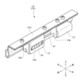
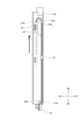
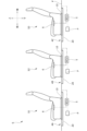
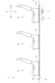
- FIG. 1 is a side view of the vehicle seat of the present embodiment. It is a perspective view of a slide rail, and is a figure showing a part of upper rail. It is a perspective view of a slide rail, and is a figure showing a part of a lower rail and an upper rail. It is a perspective view of a power supply rail.
- FIG. 3 is a side view of the power supply rail.
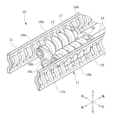
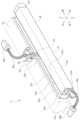
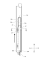
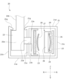
- FIG. 3 is a view of the inside of the case of the power supply rail viewed from above, showing a state in which the slide portion is in the forward position.
- FIG. 3 is a diagram showing the inside of the case of the power supply rail viewed from above, with the slide portion in an intermediate position.
- FIG. 3 is a side view of the power supply rail.
- FIG. 4 is a diagram showing the inside of the case of the power supply rail viewed from above, with the slide portion in the rear position.
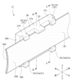
- 6B is a sectional view taken along line VII-VII of FIG. 6B. It is a perspective view of a holding member, and is a figure showing a state attached to a guide belt.
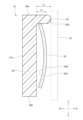
- 9 is a sectional view taken along line IX-IX in FIG. 8.
- FIG. 9 is a sectional view taken along line XX in FIG. 8.
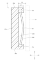
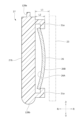
- FIG. 7 It is a figure which shows the modification of a holding member.
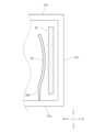
- FIG. 7 is a diagram illustrating a guide rail and a flexible flat cable in the power supply rail of Modification 1.
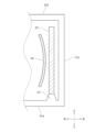
- FIG. 7 is a diagram illustrating a guide rail and a flexible flat cable in a power supply rail of Modification 2.
- FIG. 7 is a diagram illustrating a guide rail and a flexible flat cable in a power supply rail of Modification 3.
- FIG. 7 is a side view of a vehicle seat according to modification 4.
- FIG. 7 is a side view of a vehicle seat according to modification 5;
- FIG. 12 is a diagram of the inside of the case of the power supply rail of Modification 5 viewed from above.
- the "front-back direction” refers to the front-back direction of the vehicle seat, and is a direction that coincides with the direction in which the vehicle travels.
- the "seat width direction” is the width direction of the vehicle seat, and is a direction that coincides with the left-right direction as seen from the occupant seated on the vehicle seat.
- the "vertical direction” refers to the vertical direction of the vehicle seat, and is a direction that coincides with the vertical direction when the vehicle is traveling on a horizontal plane.
- the vehicle seat S is attached to a seat cushion 1, a seat back 2, a seat support member 3, a seat main body, and a floor F of a vehicle body, and is mounted in a predetermined direction in a specific manner.
- the rail device 4 is mainly composed of a rail device 4 that supports the rail device 4 so as to be movable in the front-rear direction, a control device 5 (ECU) that controls the rail device 4, and a switch 6 for operating the rail device 4 to move it.
- the seat cushion 1 is a seating portion that supports an occupant from below, and is constructed by placing a padding material 1a on a cushion frame serving as a skeleton and covering it with a skin material 1b.
- the seat back 2 is a backrest portion that supports the back of an occupant from behind, and is configured by placing a pad material 2a on a back frame serving as a skeleton and covering it with a skin material 2b.
- the seat support member 3 is a member that supports the seat cushion 1 and the seat back 2, and is attached to the rail device 4.
- the control device 5 is an electronic control device, and is connected to a power source P mounted on the vehicle body, the rail device 4, and the switch 6.
- the switch 6 is provided on the side of the seat support member 3 and has a button corresponding to forward movement and a button corresponding to backward movement. An occupant sits on the seat cushion 1 and operates the switch 6 to operate the rail device 4, thereby being able to move the vehicle seat S back and forth with respect to the floor F.
- the rail device 4 includes a slide rail 10 that extends in a predetermined direction, which is the front-rear direction, and a power supply rail 20 that is provided on the side of the slide rail 10 and extends in the front-rear direction.
- a pair of left and right slide rails 10 are provided.
- the slide rail 10 is a rail member that supports the seat body so as to be movable back and forth with respect to the floor F, and includes a lower rail 11 fixed to the floor F and a seat support member 3. It has an upper rail 12 fixed to.
- the power supply rail 20 is a power supply device that electrically connects a power supply P provided in the vehicle body and the vehicle seat S, and supplies power from the power supply P to the slide rail 10.
- the rail device 4 is arranged in a rail groove formed in the floor F, as shown in FIG.
- the upper surface of the rail device 4 is arranged on the same plane as the upper surface of the floor F.
- the power supply rail 20 is arranged on the left side of the left slide rail 10 in the seat width direction.
- the power supply rail 20 is not limited thereto, and may be arranged on the right side of the left slide rail 10 or on the side of the right slide rail 10.
- the slide rail 10 is a rail member that supports the seat body movably in a predetermined direction, specifically, in the front-back direction. As shown in FIGS. 2 and 3, the slide rail 10 includes a lower rail 11 that extends in the front-rear direction, and an upper rail 12 that is attached to the lower rail 11 so as to be movable back and forth and extends in the front-rear direction.
- the lower rail 11 includes a rail bottom wall fixed to the floor F, left and right rail outer walls extending upward from the left and right edges of the rail bottom wall, and rail tops extending in a direction approaching each other from the upper ends of the left and right rail outer walls. It has a wall and left and right rail inner walls 11a extending downward from the end of the rail upper wall. In addition, in FIG. 3, only the rail inner wall 11a of the lower rail 11 is shown.
- the upper rail 12 is fixed to the lower part of the seat support member 3 and is provided so as to be movable back and forth with respect to the lower rail 11. Both side walls of the upper rail 12 are provided at positions facing the rail inner wall 11a, respectively. Note that the upper rail 12 is formed shorter than the lower rail 11 in the front-rear direction.
- the upper rail 12 includes an electric motor 13, a drive shaft 14 connected to the output shaft of the electric motor 13, a gear case 15 connected to the drive shaft 14, and a screw member housed in the gear case 15. 16.
- the upper rail 12 slides in the front-rear direction with respect to the lower rail 11 by driving the screw member 16 by the electric motor 13 .
- the upper rail 12 is attached to the lower rail 11 via, for example, wheels, balls, roller bearings, etc., so that the upper rail 12 can smoothly slide relative to the lower rail 11.
- the electric motor 13 is a drive unit that slides the upper rail 12, and is supplied with electric power from the power supply rail 20 via a connector (not shown).
- the electric motor 13 is formed in a cylindrical shape extending in the front-rear direction, and is attached to the upper surface 12a of the upper rail 12 via a motor bracket 13a.
- the drive shaft 14 is a rotating shaft that drives the screw member 16 and is connected to the output shaft of the electric motor 13.
- the drive shaft 14 extends in the front-rear direction and is rotatably supported by the gear case 15.
- the output shaft of the electric motor 13 and the drive shaft 14 are arranged on the same straight line.
- the gear case 15 is formed in the shape of a rectangular parallelepiped box that is long in the front-rear direction, and accommodates the screw member 16.
- the gear case 15 is attached to the upper surface 12a of the upper rail 12 in front of the electric motor 13 via a gear bracket 15a.
- the gear case 15 is formed with a case opening 15b, which is an opening for laterally exposing the screw member 16.
- the screw member 16 includes a first screw member 17 and a second screw member 18, which are provided so as to be movable in the front and rear directions with respect to the lower rail 11.
- the first screw member 17 and the second screw member 18 each extend back and forth and are arranged in parallel to each other in the gear case 15.
- the first screw member 17 is arranged along the right side of the gear case 15, and the second screw member 18 is arranged along the left side of the gear case 15.
- the drive shaft 14 is arranged below an intermediate portion between the first screw member 17 and the second screw member 18.
- the screw member 16 is provided as a pair at both ends of the first screw member 17 and the second screw member 18 in the front-rear direction, and has a bearing portion 16A that pivotally supports the drive shaft 14, the first screw member 17, and the second screw member 18. .
- the bearing portion 16A includes a first bearing portion 16a that rotatably supports the front end and rear end of the first screw member 17, and a second bearing portion 16a that rotatably supports the front end and rear end of the second screw member 18. It has two bearing parts 16b and a third bearing part 16c that rotatably supports the drive shaft 14.
- a drive gear (not shown) that meshes with the drive shaft 14 causes the first screw member 17 and the second screw member 18 to rotate in the same direction.
- the lower rail 11 is formed with a screw engaging portion 19 that engages with the screw member 16.
- the first engaging portion 19a is formed on the right rail inner wall 11a of the upper rail 12 adjacent to the first screw member 17.
- a second engaging portion 19b is formed on the left rail inner wall 11a of the upper rail 12 adjacent to the second screw member 18.
- the first engaging portion 19a and the second engaging portion 19b are holes formed in plural numbers in the rail inner wall 11a in a line in the front-rear direction. Therefore, when the screw member 16 rotates due to the rotation of the drive shaft 14, the first screw member 17 engages with the hole of the first engaging portion 19a, and the second screw member 18 engages with the hole of the second engaging portion 19b.
- the upper rail 12 moves in the front-back direction with respect to the lower rail 11.
- the power supply rail 20 is a power supply device that supplies power from the power supply P to the slide rail 10. As shown in FIGS. 1 and 4, the power supply rail 20 is arranged on the side of the slide rail 10 along the direction in which the slide rail 10 extends.
- the power supply rail 20 includes a case 21 extending in a predetermined direction, that is, the front-back direction, a slide portion 22 that slides as the upper rail 12 moves, and a flexible flat cable 23 for supplying power from the power source P to the slide rail 10.
- the case 21 is a cylindrical member made of metal such as aluminum and extending in a predetermined direction, that is, the front-rear direction.
- the case 21 is arranged adjacent to the slide rail 10 in a rail groove formed in the floor F.
- the case 21 includes a case bottom wall 21a fixed to a rail groove of the floor F, and a right wall portion 21b and a left wall extending upward from both left and right ends of the case bottom wall 21a substantially perpendicularly to the case bottom wall 21a.
- an upper wall part 21d extending to the right from the upper end of the left wall part 21c substantially parallel to the case bottom wall 21a, and a top wall part 21d extending downward from the tip of the upper wall part 21d substantially parallel to the left wall part 21c. It has an inner wall portion 21e connected to the bottom wall 21a.
- the case 21 has a slit 21f extending in the front-rear direction between the left wall portion 21c and the middle wall portion 21e.
- the slide portion 22 is slidable relative to the case 21 via the slit 21f.
- a canopy portion 21g is formed at the opening of the slit 21f.
- the eaves portion 21g extends downwardly from the right wall portion 21b and the middle wall portion 21e toward the inside of the slit 21f. The eaves portion 21g makes it difficult for foreign matter to enter the case 21 through the slit 21f, so that disconnection of the flexible flat cable 23 can be suppressed.
- a fixed terminal portion 25 is connected to the front end portion 21h of the case 21.
- a cover 21j is attached to the front end 21h and rear end 21i of the case 21. That is, a space surrounded by the case bottom wall 21a, left wall 21c, top wall 21d, and middle wall 21e of the case 21 is closed by the cover 21j. Further, an opening 21k for allowing the slide portion 22 to pass through in the left-right direction is formed in the middle portion of the inner wall portion 21e in the vertical direction. The opening 21k is formed in the inner wall portion 21e so as to extend in the front-rear direction.
- the slide portion 22 is slidably attached to the case 21 along the front-rear direction.
- the slide portion 22 includes a main body portion 22a disposed within the slit 21f, a protrusion portion 22b extending upward from the main body portion 22a and protruding above the upper wall portion 21d, and a connector mounting portion provided at the upper end of the protrusion portion 22b. 22c, a connecting portion 22d extending leftward from the main body portion 22a through the opening 21k, and a flat cable attachment portion 22e to which the flexible flat cable 23 is attached.
- the connector mounting portion 22c is arranged above the slide rail 10 (specifically, the upper surface of the lower rail 11) and the upper wall portion 21d of the case 21.
- the slide rail 10 specifically, the upper surface of the lower rail 11
- the upper wall portion 21d of the case 21 When the seat support member 3 moves in the front-rear direction by the slide rail 10, a portion of the seat support member 3 comes into contact with the connector attachment part 22c, so that the slide part 22 moves in the front-rear direction together with the seat support member 3. Therefore, when the seat support member 3 moves in the front-rear direction by the slide rail 10, the movable terminal part 24 provided on the connector mounting part 22c also moves in the front-rear direction. , power can always be supplied to the upper rail 12.
- the flexible flat cable 23 is a group of flexible transmission lines in which a plurality of metal plates (for example, copper plates) made of conductors are arranged in the width direction and their outer surfaces are covered with heat-resistant insulating tape. As shown in FIGS. 4 to 6A, the flexible flat cable 23 is housed in the case 21 and extends along the front-rear direction. Specifically, the flexible flat cable 23 extends in the vertical direction along the protrusion 22b, is bent and attached to the flat cable attachment part 22e, and extends rearward within the case 21. Then, the flexible flat cable 23 is bent and folded back within the case 21, extends toward the front, and is connected to the fixed terminal portion 25 at the front end portion 21h of the case 21.
- metal plates for example, copper plates
- the flexible flat cable 23 is a long belt-shaped cable that extends substantially in the front-rear direction.
- the flexible flat cable 23 is installed in a case such that the thickness direction of the flexible flat cable 23 matches the left-right direction of the case 21, the width direction matches the up-down direction of the case 21, and the length direction matches the front-back direction of the case 21. 21.
- the flexible flat cable 23 has a distal end portion 23a connected to the movable terminal portion 24, a proximal end portion 23b connected to the fixed terminal portion 25, and a curved intermediate portion provided between the distal end portion 23a and the proximal end portion 23b. 23c.
- the intermediate portion 23c is a portion of the cable intermediate portion between the distal end portion 23a and the proximal end portion 23b of the flexible flat cable 23, and is a portion that curves into a substantially U-shape when viewed from above as the slide portion 22 moves. It is.
- the movable terminal portion 24 is provided at the tip portion 23a of the flexible flat cable 23 and attached to the connector attachment portion 22c of the slide portion 22, as shown in FIGS. 4 to 6A.
- the movable terminal section 24 includes a movable cable 24a that connects to the tip end 23a of the flexible flat cable 23, and a movable connector 24b that connects to a connector (not shown) of the upper rail 12.
- the movable terminal portion 24 provided on the connector mounting portion 22c also moves in the front-rear direction. Therefore, power can be supplied to the upper rail 12 by moving the movable connector 24b in accordance with the movement of the upper rail 12 in the front-rear direction.
- the fixed terminal portion 25 is provided at the base end portion 23b of the flexible flat cable 23 and attached to the front end portion 21h of the case 21, as shown in FIGS. 4 to 6A.
- the fixed terminal section 25 includes a fixed cable 25a connected to the base end 23b of the flexible flat cable 23, and a fixed connector 25b connected to a power source P provided in the vehicle body. Fixed connector 25b is connected to power supply P via control device 5. By electrically connecting the fixed terminal section 25 and the movable terminal section 24 via the flexible flat cable 23, power from the power source P can be supplied to the slide rail 10.
- the guide belt 26 is housed in the case 21, extends along the front-rear direction, and guides the flexible flat cable 23. Specifically, the guide belt 26 is attached to the slide portion 22 together with the flexible flat cable 23, and extends rearward within the case 21. The guide belt 26 is then bent and folded back within the case 21, extends forward, and is fixed to the front end 21h of the case 21.
- the guide belt 26 is a long belt-shaped guide member that extends substantially in the front-rear direction.
- the guide belt 26 is made of, for example, a metal material such as stainless steel or a resin material.
- the guide belt 26 is installed inside the case 21 so that the thickness direction of the guide belt 26 matches the left-right direction of the case 21, the width direction matches the up-down direction of the case 21, and the length direction matches the front-back direction of the case 21.
- the guide belt 26 has an arcuate cross-sectional shape convex toward the flexible flat cable 23. As shown in FIG.
- the guide belt 26 is arranged such that the convex surface 26A faces the flexible flat cable 23.
- the guide belt 26 has a movable end portion 26a attached to the slide portion 22 together with the distal end portion 23a of the flexible flat cable 23, a fixed end portion 26b fixed to the case 21 together with the base end portion 23b, and a movable end portion 26a and a fixed end. It has a curved part 26c which is provided between the part 26b and the curved part 26c.
- the curved portion 26c is a portion of the intermediate portion of the guide belt 26 between the movable end portion 26a and the fixed end portion 26b, and is a portion that curves into a substantially U-shape when viewed from above as the slide portion 22 moves. It is.
- the moving end portion 26a is attached to the slide portion 22, and moves in the front-back direction together with the tip portion 23a of the flexible flat cable 23 in accordance with the back-and-forth movement of the slide portion 22.
- the fixed end portion 26b is attached to the front end portion 21h of the case 21, and is fixed to the case 21 together with the base end portion 23b of the flexible flat cable 23.
- the curved portion 26c is provided so as to curve along the flexible flat cable 23, and guides the flexible flat cable 23.
- the holding member 27 is a member that holds the guide belt 26 in order to suppress rattling of the guide belt 26 in the vertical direction, and is made of resin or the like.
- the holding member 27 is provided between the fixed end portion 26b and the curved portion 26c of the guide belt 26, and is provided with a base portion 28 disposed on the right side of the guide belt 26, and is provided on the base portion 28 and locks the guide belt 26.
- a locking portion 29 is provided.
- the holding member 27 when the slide portion 22 is in the forward position, the holding member 27 is located near the curved portion 26c. As shown in FIG. 6B, when the slide portion 22 moves rearward and is in the intermediate position, the holding member 27 is located between the fixed end portion 26b and the curved portion 26c. As shown in FIG. 6C, when the slide portion 22 moves further rearward and is in the rear position, the holding member 27 is positioned between the fixed end portion 26b separated from the curved portion 26c and the curved portion 26c. . In this way, the guide belt 26 is held by the locking part 29 of the holding member 27 between the fixed end part 26b and the curved part 26c.
- the downward bending moment applied to the curved portion 26c is reduced regardless of the position of the curved portion 26c in the front-rear direction, and deformation of the guide belt 26 due to gravity or the like is suppressed. Therefore, the lower edge of the guide belt 26 is less likely to come into contact with the case bottom wall 21a of the case 21, and the generation of abnormal noise can be suppressed.
- the holding member 27 is provided in the case 21 so as to face the concave surface 26B of the guide belt 26. That is, the base portion 28 is provided at a position facing the concave surface 26B of the guide belt 26 on the side opposite to the convex surface 26A on the flexible flat cable 23 side.
- the holding member 27 may be provided on the case 21 so as to face the convex surface 26A of the guide belt 26. That is, the base portion 28 may be provided at a position facing the convex surface 26A of the guide belt 26 on the flexible flat cable 23 side (between the guide belt 26 and the flexible flat cable 23).
- the base portion 28 is, for example, a long plate-shaped member that extends in the front-rear direction along the guide belt 26. As shown in FIG. 8, the base portion 28 is arranged at a position overlapping the guide belt 26 in the left-right direction, which is the thickness direction of the guide belt 26.
- the locking portion 29 is a portion that locks an end (upper end or lower end) of the guide belt 26 in the width direction.
- the locking portions 29 are provided at a central portion 27a, a front portion 27b, and a rear portion 27c of the holding member 27 so as to protrude from the base portion 28 toward the guide belt 26.
- the locking portion 29 extends leftward from the end of the base portion 28 in the vertical direction, and overlaps the guide belt 26 in the vertical direction.
- the locking portions 29 are provided at three locations in the holding member 27: a central portion 27a, a front portion 27b, and a rear portion 27c.
- the locking portion 29 is not limited thereto, and the locking portion 29 may be provided in any one of the central portion 27a, the front portion 27b, and the rear portion 27c.
- the locking portion 29 includes a bulge portion 30 that locks the upper end of the guide belt 26, and a claw portion 31 that locks the upper and lower ends of the guide belt 26. That is, the guide belt 26 is housed in a space surrounded by the base portion 28, the bulge portion 30 of the locking portion 29, and the claw portion 31.
- the locking portion 29 has a bulging portion 30 provided in the center portion 27a, a front locking piece 31a provided in the front side portion 27b, and a rear locking piece 31b provided in the rear side portion 27c.
- the present invention is not limited thereto, and the bulging portion 30 may be provided on the front portion 27b and the rear portion 27c, and the claw portion 31 may be provided on the central portion 27a.
- the bulging portion 30 may be provided in all of the central portion 27a, the front portion 27b, and the rear portion 27c, and the claw portion 31 may be provided in all of the central portion 27a, the front portion 27b, and the rear portion 27c. Good too.
- the bulging portion 30 extends leftward from the upper end portion 28a of the base portion 28 at a central position (center portion 27a) in the longitudinal direction, which is the extending direction of the base portion 28. , overlaps the guide belt 26 in the vertical direction. That is, the bulge 30 locks the upper end of the guide belt 26.
- the lower surface of the bulge 30 contacts the upper end of the guide belt 26
- the distal end surface 30 a of the bulge 30 contacts the flexible flat cable 23 .
- the distal end surface 30a of the bulging portion 30 has a rounded shape.
- the bulging part 30 is provided at the upper end part 28a, but it may be provided at the lower end part 28b. Further, the bulging portion 30 may be provided on both the upper end portion 28a and the lower end portion 28b.
- the claw portion 31 extends leftward from the upper end 28a and the lower end 28b of the base 28 at both end portions (front portion 27b, rear portion 27c) of the base portion 28 in the front-rear direction. and overlap in the vertical direction. That is, the claw portion 31 locks the upper and lower ends of the guide belt 26.
- the claw part 31 is provided at the upper end part 28a and the lower end part 28b, but it may be provided at either one side of the upper end part 28a or the lower end part 28b.
- the length L1 of the bulging portion 30 is longer than the length L2 of the claw portion 31 in the left-right direction. Therefore, since the bulging portion 30, which is longer than the claw portion 31, comes into contact with the flexible flat cable 23, the guide belt 26 is held at a position separated from the flexible flat cable 23. Furthermore, even when the distal end surface 30a of the bulging portion 30 comes into contact with the flexible flat cable 23, the flexible flat cable 23 is abraded by the holding member 27 because the distal end surface 30a has a rounded shape. can be suppressed.
- the holding member 27 can stably hold the guide belt 26 by holding the ends of the guide belt 26 in the vertical direction using the locking portions 29.
- the lower edge of the guide belt 26 is less likely to collide with the case bottom wall 21a of the case 21 at the curved portion 26c.
- the holding member 27 may be attached so as to be in contact with the case 21.
- the holding member 27 may be held in the case 21 by the urging force of the elastic member.
- the locking portion 29 shown in FIG. 10A extends from the upper and lower end surfaces of the base portion 28 in the thickness direction of the base portion 28, overlaps the guide belt 26 in the vertical direction, and holds the end portion of the guide belt 26 in the vertical direction. do.
- the present invention is not limited thereto, and as shown in FIG. 10B, the locking portion 29 may be provided at the upper and lower ends of the base portion 28 closer to the center than the upper and lower end surfaces. Note that the upper and lower ends of the base portion 28 refer to portions other than the central portion in the vertical direction.
- the base portion 28 of the holding member 27 has a stepped upper end portion 128a in which a step is formed on the upper end surface, and a curved lower end portion 128b in which a curved surface is formed in the lower end surface. .
- the thickness at the upper and lower end portions of the base portion 28 is thinner than the thickness at the center portion.
- ⁇ Manufacturing method> A method for manufacturing the vehicle seat S will be explained. First, an operator prepares a seat body including a seat cushion 1 and a seat back 2. Then, the operator attaches the seat body to the slide rail 10 extending in a predetermined direction, which is the front-back direction, so as to be movable in the front-back direction. Specifically, the operator fixes the seat support member 3 of the seat body above the upper rail 12 of the slide rail 10.
- the operator places the power supply rail 20 on the side of the slide rail 10 along the direction in which the slide rail 10 extends. Specifically, the worker places the case 21 of the power supply rail 20 in the rail groove formed in the floor F so as to be adjacent to the slide rail 10. Further, the operator electrically connects the movable terminal portion 24 of the power supply rail 20 to the slide rail 10. Specifically, the operator connects the movable terminal portion 24 connected to the tip portion 23a of the flexible flat cable 23 to a connector (not shown) provided on the upper rail 12 of the slide rail 10. Further, the operator electrically connects the fixed terminal portion 25 of the power supply rail 20 to a power source P provided in the vehicle body. By doing so, power from the power source P is supplied to the upper rail 12 of the slide rail 10 via the power supply rail 20.
- the power supply rail 20 includes a case 21 that extends in the front-rear direction and has a cylindrical shape, a slide portion 22 that is attached to the case 21 so as to be movable in the front-rear direction, and a slide portion 22 that is housed in the case 21 and that extends in the front-rear direction.
- a flexible flat cable 23 extending along the flexible flat cable 23; a movable terminal part 24 provided at the tip end 23a of the flexible flat cable 23 and attached to the slide part 22; and a movable terminal part 24 provided at the base end 23b of the flexible flat cable 23 and attached to the case 21.
- a guide belt 26 that is housed in the case 21 and extends in the front-rear direction along the flexible flat cable 23 to guide the flexible flat cable 23, and a holding member 27 that holds the guide belt 26.
- the flexible flat cable 23 has a distal end portion 23a connected to the movable terminal portion 24 and a base end portion 23b connected to the fixed terminal portion.
- the guide belt 26 has a movable end portion 26a attached to the slide portion 22 together with the distal end portion 23a, a fixed end portion 26b fixed to the case 21 together with the proximal end portion 23b, and a movable end portion 26b between the movable end portion 26a and the fixed end portion 26b. It has a curved portion 26c that is provided in and curved.
- the holding member 27 is provided between the fixed end portion 26b and the curved portion 26c, and includes a base portion 28 arranged at a position overlapping with the guide belt 26 in the left-right direction, and a base portion 28 that is arranged in the left-right direction from the upper end or the lower end of the base portion 28. It has a locking part 29 that extends to and overlaps the guide belt 26 in the vertical direction.
- the holding member 27 holds the guide belt 26 by the locking portion 29.
- the base portion 28 extends in the front-rear direction along the guide belt 26, and the bulging portion 30 of the locking portion 29 extends in the left-right direction from the upper end in the central portion in the extending direction of the base portion 28. It is preferable to overlap the guide belt 26 in the vertical direction. Further, the base portion 28 extends in the front-rear direction along the guide belt 26, and the claw portion 31 of the locking portion 29 extends in the left-right direction from the upper end or the lower end at the side end portion in the extending direction of the base portion 28. It is preferable that it extends and overlaps the guide belt 26 in the vertical direction.
- the base portion 28 may extend in the front-rear direction along the guide belt 26 and be provided at a position facing the concave surface 26B of the guide belt 26 on the side opposite to the convex surface 26A on the flexible flat cable 23 side. Further, the length of the bulging portion 30 is preferably longer than the length of the claw portion 31 in the left-right direction.
- a method for manufacturing a vehicle seat comprising: A seat body including a seat cushion and a seat back is prepared, the seat body is attached to a slide rail extending in a predetermined direction so as to be movable in the predetermined direction; arranging a power supply rail on the side of the slide rail along the direction in which the slide rail extends,
- the power supply rail is a case extending in the predetermined direction and having a cylindrical shape; a slide portion movably attached to the case along the predetermined direction; a flexible flat cable housed in the case and extending along the predetermined direction; a movable terminal section provided at one end of the flexible flat cable and attached to the slide section; a fixed terminal section provided at the other end of the flexible flat cable and attached to the case; a guide belt that is housed in the case, extends in the predetermined direction along the flexible flat cable, and guides the flexible flat cable; A holding member that holds the guide belt,
- the flexible flat cable has a distal end portion connected
- the holding member has a locking portion that is provided between the fixed end portion and the curved portion and locks at least one end of the guide belt in the width direction, and the holding member locks the guide belt by the locking portion. hold the belt
- a method for manufacturing a vehicle seat further comprising electrically connecting the movable terminal portion of the power supply rail to the slide rail.
- the holding member includes a base portion disposed at a position overlapping the guide belt in the thickness direction of the guide belt, and the locking portion, The locking portion extends from at least one end of the base portion in the width direction of the guide belt in the thickness direction, and overlaps the guide belt in the width direction.
- the base portion extends in the predetermined direction along the guide belt
- the locking portion extends from at least one end of the base portion in the width direction in the thickness direction at a central portion in the extending direction of the base portion, and overlaps the guide belt in the width direction.
- the base portion extends in the predetermined direction along the guide belt
- the locking portion extends in the thickness direction from at least one end of the base portion in the width direction at at least one side end portion in the extending direction of the base portion, and the locking portion extends in the thickness direction from at least one end portion of the base portion in the width direction.
- the base portion extends in the predetermined direction along the guide belt
- the locking portion extends from at least one end of the base portion in the width direction in the thickness direction at both end portions in the extending direction of the base portion, and overlaps the guide belt in the width direction.
- the base portion extends in the predetermined direction along the guide belt, and is provided at a position facing a surface of the guide belt opposite to a surface on the flexible flat cable side,
- the locking portion extends from both ends of the base portion in the width direction in the thickness direction, and overlaps the guide belt in the width direction.
- the base portion extends in the predetermined direction along the guide belt, and is provided at a position facing a surface of the guide belt opposite to a surface on the flexible flat cable side
- the locking portion is a bulge that extends in the thickness direction from at least one end of the base portion in the width direction and overlaps with the guide belt in the width direction, at a central portion in the extending direction of the base portion. and a claw portion extending from at least one end of the base portion in the width direction in the thickness direction and overlapping the guide belt in the width direction, at both end portions in the extending direction of the base portion.
- a protrusion 23d is formed on the flexible flat cable 23. More specifically, a protrusion 23d is formed at the lower end of the flexible flat cable 23.
- the protrusions 23d have a substantially inverted triangular shape when viewed from the left and right directions, and a plurality of protrusions (for example, three) are formed side by side in the front-rear direction.
- the protruding portion 23d is formed, for example, between the base end portion 23b and the intermediate portion 23c of the flexible flat cable 23, and is provided on the front side of the holding member 27.
- a protruding piece 26d is formed on the guide belt 26.
- a protruding piece 26d is formed at the lower end of the guide belt 26.
- the protruding pieces 26d have a substantially inverted triangular shape when viewed from the left and right directions, and a plurality of protruding pieces (for example, three pieces) are formed side by side in the front-back direction.
- the position where the protruding piece 26d is formed is, for example, between the fixed end portion 26b and the curved portion 26c of the guide belt 26, and provided on the front side of the holding member 27.
- a raised portion 21l is formed on the case bottom wall 21a of the case 21.
- a protrusion 21l that protrudes upward from the case bottom wall 21a is formed at a position corresponding to the flexible flat cable 23 on the case bottom wall 21a (near the left wall portion 21c).
- the raised portion 21l has a substantially trapezoidal cross-sectional shape when viewed from the front-rear direction, and is formed to extend in the front-rear direction.
- the position where the raised portion 21l is formed is, for example, a position corresponding to between the base end portion 23b and the intermediate portion 23c of the flexible flat cable 23 on the case bottom wall 21a, and is provided on the front side of the holding member 27. .
- the vehicle seat S of Modified Example 4 is a vehicle equipped with three rows of seats in the front-rear direction, a front seat S1 corresponding to the front seat of the vehicle, a middle seat S2 in the second row, , and a third row rear seat S3.
- the vehicle seat S includes a plurality of rail devices 4 that support each seat body so as to be movable back and forth.
- the vehicle seat S includes a front rail device 4A that supports the seat body of the front seat S1 so as to be movable back and forth, a middle rail device 4B that supports the seat body of the middle seat S2 so as to be movable back and forth, and a rear seat S3. and a rear rail device 4C that supports the seat body so as to be movable back and forth.
- control devices 5 and power sources P are provided and connected to each rail device 4; however, the present invention is not limited to this, and one control device 5 and power source P may be common to each rail device 4. may be provided.
- the vehicle seat S of Modification Example 5 is a vehicle equipped with three rows of seats in the front-rear direction, a front seat S1 corresponding to the front seat of the vehicle, a middle seat S2 in the second row, , and a third row rear seat S3.
- the vehicle seat S includes a long rail device 4D that supports each seat body so as to be movable back and forth.
- the long rail device 4D includes a long power supply rail 40 that supplies power to the slide rail 10 of the front seat S1, the slide rail 10 of the middle seat S2, and the slide rail 10 of the rear seat S3.
- the long power supply rail 40 has a long case 41 that extends long in the front-rear direction, and accommodates a power supply mechanism for each vehicle seat S.
- the long power supply rail 40 includes a first slide portion 42a for the front seat S1, a second slide portion 42b for the middle seat S2, and a third slide portion 42c for the rear seat S3.
- the long power supply rail 40 includes a first flexible flat cable 43a for the front seat S1, a second flexible flat cable 43b for the middle seat S2, and a third flexible flat cable 43c for the rear seat S3.
- the long power supply rail 40 includes a first guide belt 46a for the front seat S1, a second guide belt 46b for the middle seat S2, and a third guide belt 46c for the rear seat S3. Further, the long power supply rail 40 includes a first holding member 47a for the front seat S1, a second holding member 47b for the middle seat S2, and a third holding member 47c for the rear seat S3.
- the direction in which the slide rail 10 and the power supply rail 20 extend is the front-rear direction, but the present invention is not limited to this.
- the slide rail 10 and the power supply rail 20 may be provided extending in the left-right direction as a predetermined direction, or may be provided extending in a direction other than the front-rear direction or the left-right direction.
- a power supply rail and a vehicle seat used in a car have been described as a specific example, but the present invention is not limited to a two-wheel seat for a motorcycle, a seat for a vehicle such as a train or a bus, a seat for an airplane or a ship, etc. It can be used for various types of seats, such as vehicle seats such as, office chairs for work, wheelchairs, children's chairs for shopping carts, etc.
- the power supply rail and vehicle seat according to the present invention have been mainly described.
- the embodiments described above are merely examples for facilitating understanding of the present invention, and do not limit the present invention.
- the present invention may be modified and improved without departing from its spirit, and it goes without saying that the present invention includes equivalents thereof.
Landscapes
- Engineering & Computer Science (AREA)
- Mechanical Engineering (AREA)
- Aviation & Aerospace Engineering (AREA)
- Transportation (AREA)
- Seats For Vehicles (AREA)
Abstract
Description
上記構成により、ガイドベルトが、固定端部と湾曲部との間に設けられた保持部材によって保持されているため、重力等によるガイドベルトの変形が発生しにくくなり、ガイドベルトとケースが接触することを抑制できる。
詳しく述べると、ガイドベルトの上端部又は下端部を係止する係止部によって、ガイドベルトが保持されるため、ガイドベルトの姿勢を安定させて、ガイドベルトがケース内面に接触することを抑制できる。
したがって、ガイドベルトとケースの接触によって異音が発生することを抑制できる。
上記構成により、ガイドベルトの幅方向において重なる係止部によって、ガイドベルトが保持されるため、ガイドベルトがケース内面に接触することを抑制できる。
上記構成により、係止部は保持部材の長さ方向における中央部分に設けられ、ガイドベルトの上端を保持するため、ガイドベルトの姿勢をより安定させて、ガイドベルトがケース内面に接触することを一層抑制できる。
上記構成により、係止部は保持部材の延在方向における側端部分に設けられ、ガイドベルトの上端又は下端を保持するため、ガイドベルトの姿勢をより安定させて、ガイドベルトがケース内面に接触することを一層抑制できる。
上記構成により、係止部は保持部材の長さ方向における延在方向における両端部分に設けられ、ガイドベルトの上端又は下端を保持するため、ガイドベルトの姿勢をより安定させて、ガイドベルトがケース内面に接触することを一層抑制できる。
上記構成により、保持部材とフレキシブルフラットケーブルとの間にガイドベルトが設けられ、ガイドベルトを覆うように保持部材が取り付けられるため、ガイドベルトの姿勢をより安定させて、ガイドベルトがケース内面に接触することを一層抑制できる。
上記構成により、爪部によってガイドベルトを係止しつつ、膨出部によってフレキシブルフラットケーブルがガイドベルトに接触することを抑制できる。
上記構成により、ガイドベルトとケースの接触によって異音が発生することを抑制できる。
また、ガイドベルトの姿勢をより安定させて、ガイドベルトがケース内面に接触することを一層抑制できる。
また、爪部によってガイドベルトを係止しつつ、膨出部によってフレキシブルフラットケーブルがガイドベルトに接触することを抑制できる。
以下の説明において、「前後方向」とは、車両用シートの前後方向であり、車両走行時の進行方向と一致する方向である。また、「シート幅方向」とは、車両用シートの幅方向であり、車両用シートに着座した乗員から見た左右方向と一致する方向である。また、「上下方向」とは、車両用シートの上下方向であり、車両が水平面を走行しているときには鉛直方向と一致する方向である。
車両用シートSは、図1に示すように、シートクッション1と、シートバック2と、シート支持部材3と、備えているシート本体と、車体のフロアFに取り付けられ、所定方向、具体的には前後方向に移動可能に支持するレール装置4と、レール装置4を制御する制御装置5(ECU)と、レール装置4を移動操作するためスイッチ6と、から主に構成されている。
シートバック2は、乗員の背中を後方から支持する背もたれ部であって、骨格となるバックフレームにパッド材2aを載置して表皮材2bで被覆されて構成されている。
乗員は、シートクッション1に着座して、スイッチ6を操作することによってレール装置4を作動させ、フロアFに対して車両用シートSを前後に移動させることができる。
スライドレール10は、図2、図3に示すように、フロアFに対して、シート本体を前後移動可能に支持するレール部材であって、フロアFに固定されるロアレール11と、シート支持部材3に固定されるアッパレール12と、を有する。
給電レール20は、図4に示すように、車体に設けられた電源Pと車両用シートSとを電気的に接続し、電源Pからスライドレール10に電力を供給するための給電装置である。
本実施形態では、図4に示すように、給電レール20は、シート幅方向における左側のスライドレール10の左側に配置される。しかし、これに限らず、給電レール20は、左側のスライドレール10右側に配置されても良く、右側のスライドレール10の側方に配置されてもよい。
スライドレール10は、シート本体を所定方向、具体的には前後方向に移動可能に支持するレール部材である。スライドレール10は、図2、図3に示すように、前後方向に延在するロアレール11と、ロアレール11に対して前後移動可能に取り付けられ、前後方向に延在するアッパレール12と、を有する。
なお、アッパレール12は、例えば車輪、ボール、ローラベアリング等を介してロアレール11に取り付けられることで、ロアレール11に対して円滑にスライド移動することができる。
第1ねじ部材17はギアケース15の右側面に沿って配置され、第2ねじ部材18はギアケース15の左側面に沿って配置される。駆動軸14は、第1ねじ部材17と第2ねじ部材18との中間部の下方に配置される。
駆動軸14が回転すると、駆動軸14に噛み合う駆動ギア(不図示)によって、第1ねじ部材17及び第2ねじ部材18は互いに同一方向に回転する。
第1係合部19a及び第2係合部19bは、レール内壁11aに前後方向に並んで複数形成された孔部である。したがって、駆動軸14の回転によって、ねじ部材16が回転すると、第1ねじ部材17が第1係合部19aの孔部と噛み合い、第2ねじ部材18が第2係合部19bの孔部と噛み合うことで、アッパレール12がロアレール11に対して前後方向に移動する。
給電レール20は、電源Pからスライドレール10に電力を供給する給電装置である。給電レール20は、図1、図4に示すように、スライドレール10が延びる方向に沿ってスライドレール10の側方に配置される。
給電レール20は、所定方向、すなわち前後方向に延びるケース21と、アッパレール12の移動に伴ってスライドするスライド部22と、電源Pからスライドレール10に電力を供給するためのフレキシブルフラットケーブル23と、フレキシブルフラットケーブル23からスライドレール10に電力を供給するための可動端子部24と、電源Pからフレキシブルフラットケーブル23に電力を供給するための固定端子部25と、フレキシブルフラットケーブル23を案内するガイドベルト26と、ガイドベルト26を保持する保持部材27と、を備える。
ケース21は、フロアFのレール溝に固定されるケース底壁21aと、ケース底壁21aの左右両端部から上方に向かってケース底壁21aに対して略垂直に延びる右壁部21b及び左壁部21cと、左壁部21cの上端からケース底壁21aと略平行に右方に延びる上壁部21dと、上壁部21dの先端から左壁部21cと略平行に下方に延びて、ケース底壁21aと接続する中壁部21eと、を有する。
スリット21fの開口部分には、ひさし部21gが形成される。具体的には、ひさし部21gは、右壁部21b及び中壁部21eからスリット21f内に向かって、下方に傾斜して延びる。ひさし部21gによって、スリット21fからケース21内に異物が進入し難くなるため、フレキシブルフラットケーブル23の断線を抑制できる。
また、中壁部21eの上下方向における中間部分には、スライド部22を左右方向において貫通させるための開口21kが形成される。開口21kは、前後方向に延びるように、中壁部21eに形成される。
したがって、シート支持部材3がスライドレール10によって前後方向に移動するとき、コネクタ取付部22cに設けられた可動端子部24も同様に前後方向に移動するため、スライドレール10のアッパレール12の近傍位置において、常にアッパレール12へ給電することができる。
図4~図6Aに示すように、フレキシブルフラットケーブル23は、ケース21に収容され、前後方向に沿って延びる。具体的には、フレキシブルフラットケーブル23は、突出部22bに沿って上下方向に延び、屈曲してフラットケーブル取付部22eに取り付けられ、ケース21内において後方へ向かって延びる。そして、フレキシブルフラットケーブル23は、ケース21内で湾曲して折り返され、前方へ向かって延び、ケース21の前端部21hにおいて固定端子部25へ接続する。
フレキシブルフラットケーブル23は、可動端子部24に接続する先端部23aと、固定端子部25に接続する基端部23bと、先端部23aと基端部23bとの間に設けられて湾曲する中間部23cと、を有する。中間部23cは、フレキシブルフラットケーブル23における先端部23aと基端部23bとの間のケーブル中間部の一部分であって、スライド部22の移動に伴って上面視で略U字状に湾曲する部分である。
上述したように、シート支持部材3がスライドレール10によって前後方向に移動するとき、コネクタ取付部22cに設けられた可動端子部24も同様に前後方向に移動する。そのため、アッパレール12の前後方向の動きに合わせて可動コネクタ24bが動くことによって、アッパレール12へ給電することができる。
固定コネクタ25bは、制御装置5を介して電源Pに接続される。フレキシブルフラットケーブル23を介して、固定端子部25と可動端子部24とが電気的に接続されることで、電源Pからの電力をスライドレール10に供給することができる。
図7に示すように、ガイドベルト26は、断面形状がフレキシブルフラットケーブル23に向かって凸となる円弧状に形成される。ガイドベルト26は、凸面26Aがフレキシブルフラットケーブル23と対向するように配置される。
固定端部26bは、ケース21の前端部21hに取り付けられ、フレキシブルフラットケーブル23の基端部23bと共にケース21に固定される。
湾曲部26cは、フレキシブルフラットケーブル23に沿って湾曲するように設けられ、フレキシブルフラットケーブル23を案内する。
このように、ガイドベルト26は、固定端部26bと湾曲部26cとの間で、保持部材27の係止部29に保持されている。これにより、湾曲部26cの前後方向における位置によらず、湾曲部26cに加えられる下方への曲げモーメントが低減され、重力等によるガイドベルト26の変形が抑制されている。したがって、ガイドベルト26の下縁がケース21のケース底壁21aに接触し難くなり、異音の発生を抑制することができる。
なお、保持部材27は、ガイドベルト26の凸面26Aと対向するように、ケース21に設けられてもよい。すなわち、ベース部28は、ガイドベルト26のフレキシブルフラットケーブル23側の凸面26Aに対向する位置(ガイドベルト26及びフレキシブルフラットケーブル23との間)に設けられてもよい。
なお、本実施形態では、係止部29が保持部材27における中央部分27a、前側部分27b、後側部分27cの3箇所に設けられている。しかしこれに限らず、係止部29は、中央部分27a、前側部分27b、後側部分27cのいずれか一部分に設けられてもよい。
なお、係止部29は、中央部分27aに膨出部30が設けられ、前側部分27bに前係止片31aが設けられ、後側部分27cに後係止片31bが設けられる。しかしこれに限らず、膨出部30が前側部分27b、後側部分27cに設けられても良く、爪部31が中央部分27aに設けられてもよい。また、中央部分27a、前側部分27b、後側部分27cの全てに膨出部30が設けられても良く、中央部分27a、前側部分27b、後側部分27cの全てに爪部31が設けられてもよい。
膨出部30の下面は、ガイドベルト26の上端に当接し、膨出部30の先端面30aは、フレキシブルフラットケーブル23に当接する。膨出部30の先端面30aは、丸みを帯びた形状となっている。
なお、本実施形態では、膨出部30が上端部28aに設けられるが、下端部28bに設けられてもよい。また、膨出部30が上端部28a及び下端部28bの両方に設けられてもよい。
なお、本実施形態では、爪部31が上端部28a及び下端部28bに設けられるが、上端部28a及び下端部28bのいずれか一方側に設けられてもよい。
なお、保持部材27の上下方向におけるがたつきを抑えるために、保持部材27がケース21に接触するように取り付けられてもよい。例えば、保持部材27に上下方向に付勢する弾性部材を設けることにより、保持部材27が弾性部材の付勢力によってケース21に保持されてもよい。
車両用シートSの製造方法について説明する。
まず、作業者は、シートクッション1とシートバック2とを備えるシート本体を用意する。そして、作業者は、所定方向である前後方向に延びるスライドレール10にシート本体を前後方向に移動可能に取り付ける。具体的には、作業者は、スライドレール10のアッパレール12の上方に、シート本体のシート支持部材3を固定する。
また、作業者は、スライドレール10に給電レール20の可動端子部24を電気的に接続する。具体的には、作業者は、スライドレール10のアッパレール12に設けられたコネクタ(不図示)に、フレキシブルフラットケーブル23の先端部23aに接続された可動端子部24を接続する。また、作業者は、給電レール20の固定端子部25を車体に設けられた電源Pに電気的に接続する。
こうすることで、電源Pからの電力が、給電レール20を介して、スライドレール10のアッパレール12に供給される。
フレキシブルフラットケーブル23は、可動端子部24に接続する先端部23aと、前記固定端子部に接続する基端部23bと、を有する。ガイドベルト26は、先端部23aと共にスライド部22に取り付けられる移動端部26aと、基端部23bと共にケース21に固定される固定端部26bと、移動端部26aと固定端部26bとの間に設けられて湾曲する湾曲部26cと、を有する。
保持部材27は、固定端部26bと湾曲部26cとの間に設けられ、左右方向においてガイドベルト26と重なる位置に配置されるベース部28と、ベース部28の上端部又は下端部から左右方向へ延びて、上下方向においてガイドベルト26と重なる係止部29と、を有する。そして、保持部材27は、係止部29によってガイドベルト26を保持する。
また、ベース部28は、ガイドベルト26に沿って前後方向に延び、係止部29の爪部31は、ベース部28の延在方向における側端部分において、上端部又は下端部から左右方向へ延びて、上下方向においてガイドベルト26と重なるとよい。
また、ベース部28は、ガイドベルト26に沿って前後方向に延び、ガイドベルト26のフレキシブルフラットケーブル23側の凸面26Aとは反対側の凹面26Bと対向する位置に設けられるとよい。
また、左右方向において膨出部30の長さは、爪部31の長さよりも長いとよい。
車両用シートの製造方法であって、
シートクッションとシートバックとを備えるシート本体を用意し、
所定方向に延びるスライドレールに、前記シート本体を前記所定方向に移動可能に取り付け、
前記スライドレールが延びる方向に沿って、前記スライドレールの側方に給電レールを配置すること、を含み、
前記給電レールは、
前記所定方向に延び、筒形状を有するケースと、
前記ケースに対して、前記所定方向に沿って移動可能に取り付けられるスライド部と、
前記ケースに収容され、前記所定方向に沿って延びるフレキシブルフラットケーブルと、
前記フレキシブルフラットケーブルの一端部に設けられ、前記スライド部に取り付けられる可動端子部と、
前記フレキシブルフラットケーブルの他端部に設けられ、前記ケースに取り付けられる固定端子部と、
前記ケースに収容され、前記フレキシブルフラットケーブルに沿って前記所定方向に延び、前記フレキシブルフラットケーブルを案内するガイドベルトと、
前記ガイドベルトを保持する保持部材と、を備え、
前記フレキシブルフラットケーブルは、前記可動端子部に接続する先端部と、前記固定端子部に接続する基端部と、を有し、
前記ガイドベルトは、前記先端部と共に前記スライド部に取り付けられる移動端部と、前記基端部と共に前記ケースに固定される固定端部と、前記移動端部と前記固定端部との間に設けられて湾曲する湾曲部と、を有し、
前記保持部材は、前記固定端部と前記湾曲部との間に設けられ、前記ガイドベルトの幅方向における少なくとも一方の端部を係止する係止部を有し、前記係止部によって前記ガイドベルトを保持し、
前記スライドレールに前記給電レールの前記可動端子部を電気的に接続することをさらに含む、車両用シートの製造方法。
前記係止部は、前記ガイドベルトの前記幅方向における前記ベース部の少なくとも一方の端部から前記厚み方向へ延びて、前記幅方向において前記ガイドベルトと重なる車両用シートの製造方法。
前記係止部は、前記ベース部の延在方向における中央部分において、前記幅方向における前記ベース部の少なくとも一方の端部から前記厚み方向へ延びて、前記幅方向において前記ガイドベルトと重なる車両用シートの製造方法。
前記係止部は、前記ベース部の延在方向における少なくとも一方の側端部分において、前記幅方向における前記ベース部の少なくとも一方の端部から前記厚み方向へ延びて、前記幅方向において前記ガイドベルトと重なる車両用シートの製造方法。
前記係止部は、前記ベース部の延在方向における両端部分において、前記幅方向における前記ベース部の少なくとも一方の端部から前記厚み方向へ延びて、前記幅方向において前記ガイドベルトと重なる車両用シートの製造方法。
前記係止部は、前記幅方向における前記ベース部の両端部から前記厚み方向へ延びて、前記幅方向において前記ガイドベルトと重なる車両用シートの製造方法。
前記係止部は、前記ベース部の延在方向における中央部分において、前記幅方向における前記ベース部の少なくとも一方の端部から前記厚み方向へ延びて、前記幅方向において前記ガイドベルトと重なる膨出部と、前記ベース部の延在方向における両端部分において、前記幅方向における前記ベース部の少なくとも一方の端部から前記厚み方向へ延びて、前記幅方向において前記ガイドベルトと重なる爪部と、を有し、
前記厚み方向において、前記膨出部の長さは、前記爪部の長さよりも長い車両用シートの製造方法。
次に、給電レール20の変形例1について、図11Aに基づいて説明する。なお、上述の給電レール20と重複する内容については説明を省略する。
変形例1の給電レール20は、図11Aに示すように、フレキシブルフラットケーブル23に突起部23dが形成されている。
詳しく述べると、フレキシブルフラットケーブル23の下端には、突起部23dが形成される。突起部23dは、左右方向から見たときに略逆三角形状であって、前後方向に複数個(例えば3個)並んで形成される。突起部23dが形成される位置は、例えば、フレキシブルフラットケーブル23の基端部23bと中間部23cとの間であって、保持部材27よりも前側に設けられる。
次に、給電レール20の変形例2について、図11Bに基づいて説明する。
変形例2の給電レール20は、図11Bに示すように、ガイドベルト26に突出片26dが形成されている。
詳しく述べると、ガイドベルト26の下端には、突出片26dが形成される。突出片26dは、左右方向から見たときに略逆三角形状であって、前後方向に複数個(例えば3個)並んで形成される。突出片26dが形成される位置は、例えば、ガイドベルト26の固定端部26bと湾曲部26cとの間であって、保持部材27よりも前側に設けられる。
次に、給電レール20の変形例3について、図11Cに基づいて説明する。
変形例3の給電レール20は、図11Cに示すように、ケース21のケース底壁21aに隆起部21lが形成されている。
詳しく述べると、ケース底壁21aのフレキシブルフラットケーブル23に対応する位置(左壁部21c近傍)には、ケース底壁21aから上方に向かって隆起する隆起部21lが形成される。隆起部21lは、前後方向から見たときに断面形状が略台形であって、前後方向に延びるように形成される。隆起部21lが形成される位置は、例えば、ケース底壁21aにおけるフレキシブルフラットケーブル23の基端部23bと中間部23cとの間に対応する位置であって、保持部材27よりも前側に設けられる。
次に、車両用シートSの変形例4について、図12に基づいて説明する。
変形例4の車両用シートSは、図12に示すように、前後方向に三列のシートを備える車両において、車両の前部座席に相当するフロントシートS1と、二列目のミドルシートS2と、三列目のリアシートS3と、を備える。
図12に示すように、車両用シートSは、各シート本体を前後移動可能に支持する複数のレール装置4を備える。詳しく述べると、車両用シートSは、フロントシートS1のシート本体を前後移動可能に支持するフロントレール装置4Aと、ミドルシートS2のシート本体を前後移動可能に支持するミドルレール装置4Bと、リアシートS3のシート本体を前後移動可能に支持するリアレール装置4Cと、を備える。
なお、本実施形態では、制御装置5及び電源Pは複数設けられ、各レール装置4に接続されるが、これに限らず、一つの制御装置5及び電源Pが各レール装置4に共通して設けられてもよい。
次に、車両用シートSの変形例5について、図13、図14に基づいて説明する。
変形例5の車両用シートSは、図13に示すように、前後方向に三列のシートを備える車両において、車両の前部座席に相当するフロントシートS1と、二列目のミドルシートS2と、三列目のリアシートS3と、を備える。
図13に示すように、車両用シートSは、各シート本体を前後移動可能に支持する長尺の長尺レール装置4Dを備える。長尺レール装置4Dは、フロントシートS1のスライドレール10と、ミドルシートS2のスライドレール10と、リアシートS3のスライドレール10とに電力を供給する長尺給電レール40を備える。
また、長尺給電レール40は、フロントシートS1用の第1フレキシブルフラットケーブル43aと、ミドルシートS2用の第2フレキシブルフラットケーブル43bと、リアシートS3用の第3フレキシブルフラットケーブル43cと、を有する。
また、長尺給電レール40は、フロントシートS1用の第1保持部材47aと、ミドルシートS2用の第2保持部材47bと、リアシートS3用の第3保持部材47cと、を有する。
ただし、上記の実施形態は、本発明の理解を容易にするための一例に過ぎず、本発明を限定するものではない。本発明は、その趣旨を逸脱することなく、変更、改良され得ると共に、本発明にはその等価物が含まれることは勿論である。
S1 フロントシート
S2 ミドルシート
S3 リアシート
F フロア
P 電源
1 シートクッション
1a パッド材
1b 表皮材
2 シートバック
2a パッド材
2b 表皮材
3 シート支持部材
4 レール装置
4A フロントレール装置
4B ミドルレール装置
4C リアレール装置
5 制御装置
6 操作スイッチ
10 スライドレール
11 ロアレール
11a レール内壁
12 アッパレール
12a 上面
13 電動モータ
13a モータブラケット
14 駆動軸
15 ギアケース
15a ギアブラケット
15b ケース開口
16 ねじ部材
16a 第1軸受部
16b 第2軸受部
16c 第3軸受部
17 第1ねじ部材
18 第2ねじ部材
19 ねじ係合部
19a 第1係合部
19b 第2係合部
20 給電レール
21 ケース
21a ケース底壁
21b 右壁部
21c 左壁部
21d 上壁部
21e 中壁部
21f スリット
21g ひさし部
21h ケース前端部
21i ケース後端部
21j カバー
21k 開口
21l 隆起部
22 スライド部
22a 本体部
22b 突出部
22c コネクタ取付部
22d 接続部
22e フラットケーブル取付部
23 フレキシブルフラットケーブル
23a 先端部
23b 基端部
23c 中間部
23d 突起部
24 可動端子部
24a 可動ケーブル
24b 可動コネクタ
25 固定端子部
25a 固定ケーブル
25b 固定コネクタ
26 ガイドベルト
26A 凹面
26B 凸面
26a 移動端部
26b 固定端部
26c 湾曲部
26d 突出片
27 保持部材
27a 中央部分
27b 前側部分(側端部分、両端部分)
27c 後側部分(側端部分、両端部分)
28 ベース部
28a 上端部
28b 下端部
128a 段差上端部
128b 曲面下端部
29 係止部
30 膨出部
31 爪部
31a 前係止片
31b 後係止片
4D 長尺レール装置
40 長尺給電レール
41 長尺ケース
42a 第1スライド部
42b 第2スライド部
42c 第3スライド部
43a 第1フレキシブルフラットケーブル
43b 第2フレキシブルフラットケーブル
43c 第3フレキシブルフラットケーブル
46a 第1ガイドベルト
46b 第2ガイドベルト
46c 第3ガイドベルト
47a 第1保持部材
47b 第2保持部材
47c 第3保持部材
Claims (8)
- 所定方向に延び、筒形状を有するケースと、
前記ケースに対して、前記所定方向に沿って移動可能に取り付けられるスライド部と、
前記ケースに収容され、前記所定方向に沿って延びるフレキシブルフラットケーブルと、
前記フレキシブルフラットケーブルの一端部に設けられ、前記スライド部に取り付けられる可動端子部と、
前記フレキシブルフラットケーブルの他端部に設けられ、前記ケースに取り付けられる固定端子部と、
前記ケースに収容され、前記フレキシブルフラットケーブルに沿って前記所定方向に延び、前記フレキシブルフラットケーブルを案内するガイドベルトと、
前記ガイドベルトを保持する保持部材と、を備え、
前記フレキシブルフラットケーブルは、前記可動端子部に接続する先端部と、前記固定端子部に接続する基端部と、を有し、
前記ガイドベルトは、前記先端部と共に前記スライド部に取り付けられる移動端部と、前記基端部と共に前記ケースに固定される固定端部と、前記移動端部と前記固定端部との間に設けられて湾曲する湾曲部と、を有し、
前記保持部材は、前記固定端部と前記湾曲部との間に設けられ、前記ガイドベルトの幅方向における少なくとも一方の端部を係止する係止部を有し、前記係止部によって前記ガイドベルトを保持することを特徴とする給電レール。 - 前記保持部材は、前記ガイドベルトの厚み方向において前記ガイドベルトと重なる位置に配置されるベース部と、前記係止部と、を有し、
前記係止部は、前記ガイドベルトの前記幅方向における前記ベース部の少なくとも一方の端部から前記厚み方向へ延びて、前記幅方向において前記ガイドベルトと重なることを特徴とする請求項1に記載の給電レール。 - 前記ベース部は、前記ガイドベルトに沿って前記所定方向に延び、
前記係止部は、前記ベース部の延在方向における中央部分において、前記幅方向における前記ベース部の少なくとも一方の端部から前記厚み方向へ延びて、前記幅方向において前記ガイドベルトと重なることを特徴とする請求項2に記載の給電レール。 - 前記ベース部は、前記ガイドベルトに沿って前記所定方向に延び、
前記係止部は、前記ベース部の延在方向における少なくとも一方の側端部分において、前記幅方向における前記ベース部の少なくとも一方の端部から前記厚み方向へ延びて、前記幅方向において前記ガイドベルトと重なることを特徴とする請求項2に記載の給電レール。 - 前記ベース部は、前記ガイドベルトに沿って前記所定方向に延び、
前記係止部は、前記ベース部の延在方向における両端部分において、前記幅方向における前記ベース部の少なくとも一方の端部から前記厚み方向へ延びて、前記幅方向において前記ガイドベルトと重なることを特徴とする請求項2に記載の給電レール。 - 前記ベース部は、前記ガイドベルトに沿って前記所定方向に延び、前記ガイドベルトの前記フレキシブルフラットケーブル側の面とは反対側の面と対向する位置に設けられ、
前記係止部は、前記幅方向における前記ベース部の両端部から前記厚み方向へ延びて、前記幅方向において前記ガイドベルトと重なることを特徴とする請求項2に記載の給電レール。 - 前記ベース部は、前記ガイドベルトに沿って前記所定方向に延び、前記ガイドベルトの前記フレキシブルフラットケーブル側の面とは反対側の面と対向する位置に設けられ、
前記係止部は、前記ベース部の延在方向における中央部分において、前記幅方向における前記ベース部の少なくとも一方の端部から前記厚み方向へ延びて、前記幅方向において前記ガイドベルトと重なる膨出部と、前記ベース部の延在方向における両端部分において、前記幅方向における前記ベース部の少なくとも一方の端部から前記厚み方向へ延びて、前記幅方向において前記ガイドベルトと重なる爪部と、を有し、
前記厚み方向において、前記膨出部の長さは、前記爪部の長さよりも長いことを特徴とする請求項2に記載の給電レール。 - シートクッションと、シートバックと、を備えるシート本体と、
前記所定方向に延び、前記シート本体を前記所定方向に移動可能に支持するスライドレールと、
請求項1に記載の給電レールと、を備え、
前記給電レールは、前記スライドレールが延びる方向に沿って、前記スライドレールの側方に配置されることを特徴とする車両用シート。
Priority Applications (2)
| Application Number | Priority Date | Filing Date | Title |
|---|---|---|---|
| CN202380039652.3A CN119173416A (zh) | 2022-05-25 | 2023-05-24 | 供电轨道及车辆用座椅 |
| US18/868,400 US20250333012A1 (en) | 2022-05-25 | 2023-05-24 | Power supply rail and vehicle seat |
Applications Claiming Priority (4)
| Application Number | Priority Date | Filing Date | Title |
|---|---|---|---|
| US202263365303P | 2022-05-25 | 2022-05-25 | |
| US63/365,303 | 2022-05-25 | ||
| JP2023-053980 | 2023-03-29 | ||
| JP2023053980A JP2023174517A (ja) | 2022-05-25 | 2023-03-29 | 給電レール及び車両用シート |
Publications (1)
| Publication Number | Publication Date |
|---|---|
| WO2023228976A1 true WO2023228976A1 (ja) | 2023-11-30 |
Family
ID=88919401
Family Applications (1)
| Application Number | Title | Priority Date | Filing Date |
|---|---|---|---|
| PCT/JP2023/019333 Ceased WO2023228976A1 (ja) | 2022-05-25 | 2023-05-24 | 給電レール及び車両用シート |
Country Status (3)
| Country | Link |
|---|---|
| US (1) | US20250333012A1 (ja) |
| CN (1) | CN119173416A (ja) |
| WO (1) | WO2023228976A1 (ja) |
Families Citing this family (1)
| Publication number | Priority date | Publication date | Assignee | Title |
|---|---|---|---|---|
| KR102978195B1 (ko) * | 2024-02-14 | 2026-06-16 | 현대트랜시스 주식회사 | 시트 전원 공급 장치 |
Citations (3)
| Publication number | Priority date | Publication date | Assignee | Title |
|---|---|---|---|---|
| JP2004210084A (ja) * | 2002-12-27 | 2004-07-29 | T S Tec Kk | 電装品装備自動車用スライドシート |
| JP2019134626A (ja) * | 2018-02-01 | 2019-08-08 | 矢崎総業株式会社 | スライドドア用の配索構造 |
| WO2019188811A1 (ja) * | 2018-03-26 | 2019-10-03 | 古河電気工業株式会社 | ケーブル巻取り装置、及びスライドシート用フラットケーブル配索構造 |
Family Cites Families (20)
| Publication number | Priority date | Publication date | Assignee | Title |
|---|---|---|---|---|
| JP3435688B2 (ja) * | 1998-07-28 | 2003-08-11 | 矢崎総業株式会社 | フレキシブル・フラット・ケーブルの保護構造 |
| US7000967B2 (en) * | 2002-12-27 | 2006-02-21 | Ts Tech Co., Ltd. | Slidable vehicle seat provided with automotive electronic parts |
| US6781058B1 (en) * | 2003-02-20 | 2004-08-24 | Stoneridge Inc., Alphabet Division | Cable guide assembly for a vehicle sliding door |
| JP4095940B2 (ja) * | 2003-08-13 | 2008-06-04 | 矢崎総業株式会社 | スライドシート用給電装置 |
| JP4263684B2 (ja) * | 2004-08-06 | 2009-05-13 | 矢崎総業株式会社 | スライド用給電装置 |
| JP4467063B2 (ja) * | 2005-01-27 | 2010-05-26 | 本田技研工業株式会社 | スライドシート給電装置 |
| DE102007017286A1 (de) * | 2007-04-12 | 2008-10-16 | Leoni Bordnetz-Systeme Gmbh | Leitungsführungseinrichtung |
| JP5179943B2 (ja) * | 2008-05-09 | 2013-04-10 | 矢崎総業株式会社 | 電線配索装置、及び、電線配索装置の製造方法 |
| TWI574479B (zh) * | 2015-11-23 | 2017-03-11 | 緯創資通股份有限公司 | 具有載片的伸縮裝置、載片以及排線 |
| JP6541034B2 (ja) * | 2015-12-22 | 2019-07-10 | 株式会社オートネットワーク技術研究所 | スライド配線装置 |
| JP6836393B2 (ja) * | 2016-12-28 | 2021-03-03 | 矢崎総業株式会社 | スライドドア用の配索構造 |
| JP6564813B2 (ja) * | 2017-05-30 | 2019-08-21 | 矢崎総業株式会社 | 電線の保護ケース |
| KR102090327B1 (ko) * | 2017-06-21 | 2020-03-17 | 미크덴시고교가부시키가이샤 | 급전 레일 |
| JP6772997B2 (ja) * | 2017-09-29 | 2020-10-21 | 株式会社オートネットワーク技術研究所 | ワイヤハーネス配索装置 |
| JP7024469B2 (ja) * | 2018-02-06 | 2022-02-24 | トヨタ自動車株式会社 | 配線及び配線を備えた車両 |
| JP7196416B2 (ja) * | 2018-04-23 | 2022-12-27 | トヨタ紡織株式会社 | 乗物用フロア構造体 |
| JP2020078169A (ja) * | 2018-11-07 | 2020-05-21 | 矢崎総業株式会社 | 配索構造 |
| EP3907104B1 (en) * | 2019-01-03 | 2025-08-20 | TS Tech Co., Ltd. | Electrically powered slide rail and vehicle seat provided with electrically powered slide rail |
| JP7646527B2 (ja) * | 2021-12-02 | 2025-03-17 | 株式会社オートネットワーク技術研究所 | ワイヤハーネス配索装置 |
| KR20230174020A (ko) * | 2022-06-20 | 2023-12-27 | 현대자동차주식회사 | 슬라이딩 시트용 와이어링 하네스 모듈 |
-
2023
- 2023-05-24 CN CN202380039652.3A patent/CN119173416A/zh active Pending
- 2023-05-24 WO PCT/JP2023/019333 patent/WO2023228976A1/ja not_active Ceased
- 2023-05-24 US US18/868,400 patent/US20250333012A1/en active Pending
Patent Citations (3)
| Publication number | Priority date | Publication date | Assignee | Title |
|---|---|---|---|---|
| JP2004210084A (ja) * | 2002-12-27 | 2004-07-29 | T S Tec Kk | 電装品装備自動車用スライドシート |
| JP2019134626A (ja) * | 2018-02-01 | 2019-08-08 | 矢崎総業株式会社 | スライドドア用の配索構造 |
| WO2019188811A1 (ja) * | 2018-03-26 | 2019-10-03 | 古河電気工業株式会社 | ケーブル巻取り装置、及びスライドシート用フラットケーブル配索構造 |
Also Published As
| Publication number | Publication date |
|---|---|
| CN119173416A (zh) | 2024-12-20 |
| US20250333012A1 (en) | 2025-10-30 |
Similar Documents
| Publication | Publication Date | Title |
|---|---|---|
| JP7436858B2 (ja) | 電動スライドレール及び電動スライドレールを備えた乗物用シート | |
| US11660986B2 (en) | Powered rail apparatus for vehicular seat | |
| JP6032125B2 (ja) | スライドシート用のワイヤハーネス配索装置 | |
| KR101034307B1 (ko) | 자동차의 파워 롱 슬라이드 리어시트 | |
| KR101987006B1 (ko) | 자동차의 전동식 슬라이딩 콘솔 | |
| JP5544247B2 (ja) | 車両用シェル型シートのシートクッションシェルユニット及び車両用シェル型シート | |
| CN108394323A (zh) | 具有可枢转上部座椅靠背支承件的座椅靠背结构 | |
| JP5097430B2 (ja) | 車両用シートのワイヤーハーネス | |
| US20170313209A1 (en) | Vehicle seat | |
| JP2006205872A (ja) | スライドシート給電装置 | |
| JP2022173433A (ja) | 車両用シート | |
| JP2023044975A (ja) | 車両 | |
| US20250333012A1 (en) | Power supply rail and vehicle seat | |
| JP2020124970A (ja) | 乗物用シート | |
| JP2023174517A (ja) | 給電レール及び車両用シート | |
| JP7095277B2 (ja) | 乗物用シート | |
| JP6015558B2 (ja) | スライドシート用のワイヤハーネス配索構造 | |
| JP2004312846A (ja) | 電気接続構造、電気接続装置及びそれを用いたシート並びにハーネス余長吸収装置 | |
| JP2008260460A (ja) | 車両の車室内構造 | |
| CN106042992B (zh) | 车辆用座椅 | |
| JP2023100122A (ja) | 車両用シート構造 | |
| JP7157317B2 (ja) | 車両用シート | |
| JP2010012866A (ja) | 車両用シート | |
| KR20100130001A (ko) | 헤드레스트 이동장치 | |
| JP2025132322A (ja) | 車両後部構造 |
Legal Events
| Date | Code | Title | Description |
|---|---|---|---|
| 121 | Ep: the epo has been informed by wipo that ep was designated in this application |
Ref document number: 23811848 Country of ref document: EP Kind code of ref document: A1 |
|
| WWE | Wipo information: entry into national phase |
Ref document number: 18868400 Country of ref document: US |
|
| NENP | Non-entry into the national phase |
Ref country code: DE |
|
| 122 | Ep: pct application non-entry in european phase |
Ref document number: 23811848 Country of ref document: EP Kind code of ref document: A1 |
|
| WWP | Wipo information: published in national office |
Ref document number: 18868400 Country of ref document: US |